EP3657526A2 - Ionenquelle mit wasserstoffgaszufuhr zur extraktionselektrode - Google Patents
Ionenquelle mit wasserstoffgaszufuhr zur extraktionselektrode Download PDFInfo
- Publication number
- EP3657526A2 EP3657526A2 EP19193653.3A EP19193653A EP3657526A2 EP 3657526 A2 EP3657526 A2 EP 3657526A2 EP 19193653 A EP19193653 A EP 19193653A EP 3657526 A2 EP3657526 A2 EP 3657526A2
- Authority
- EP
- European Patent Office
- Prior art keywords
- plate member
- extraction electrode
- ion source
- gas
- plasma generation
- Prior art date
- Legal status (The legal status is an assumption and is not a legal conclusion. Google has not performed a legal analysis and makes no representation as to the accuracy of the status listed.)
- Withdrawn
Links
Images




Classifications
-
- H—ELECTRICITY
- H01—ELECTRIC ELEMENTS
- H01J—ELECTRIC DISCHARGE TUBES OR DISCHARGE LAMPS
- H01J37/00—Discharge tubes with provision for introducing objects or material to be exposed to the discharge, e.g. for the purpose of examination or processing thereof
- H01J37/30—Electron-beam or ion-beam tubes for localised treatment of objects
- H01J37/317—Electron-beam or ion-beam tubes for localised treatment of objects for changing properties of the objects or for applying thin layers thereon, e.g. for ion implantation
- H01J37/3171—Electron-beam or ion-beam tubes for localised treatment of objects for changing properties of the objects or for applying thin layers thereon, e.g. for ion implantation for ion implantation
-
- H—ELECTRICITY
- H01—ELECTRIC ELEMENTS
- H01J—ELECTRIC DISCHARGE TUBES OR DISCHARGE LAMPS
- H01J27/00—Ion beam tubes
- H01J27/02—Ion sources; Ion guns
- H01J27/022—Details
- H01J27/024—Extraction optics, e.g. grids
-
- H—ELECTRICITY
- H01—ELECTRIC ELEMENTS
- H01J—ELECTRIC DISCHARGE TUBES OR DISCHARGE LAMPS
- H01J27/00—Ion beam tubes
- H01J27/02—Ion sources; Ion guns
- H01J27/20—Ion sources; Ion guns using particle beam bombardment, e.g. ionisers
- H01J27/22—Metal ion sources
-
- H—ELECTRICITY
- H01—ELECTRIC ELEMENTS
- H01J—ELECTRIC DISCHARGE TUBES OR DISCHARGE LAMPS
- H01J37/00—Discharge tubes with provision for introducing objects or material to be exposed to the discharge, e.g. for the purpose of examination or processing thereof
- H01J37/02—Details
- H01J37/04—Arrangements of electrodes and associated parts for generating or controlling the discharge, e.g. electron-optical arrangement or ion-optical arrangement
- H01J37/08—Ion sources; Ion guns
-
- H—ELECTRICITY
- H01—ELECTRIC ELEMENTS
- H01J—ELECTRIC DISCHARGE TUBES OR DISCHARGE LAMPS
- H01J2237/00—Discharge tubes exposing object to beam, e.g. for analysis treatment, etching, imaging
- H01J2237/006—Details of gas supplies, e.g. in an ion source, to a beam line, to a specimen or to a workpiece
-
- H—ELECTRICITY
- H01—ELECTRIC ELEMENTS
- H01J—ELECTRIC DISCHARGE TUBES OR DISCHARGE LAMPS
- H01J2237/00—Discharge tubes exposing object to beam, e.g. for analysis treatment, etching, imaging
- H01J2237/02—Details
- H01J2237/022—Avoiding or removing foreign or contaminating particles, debris or deposits on sample or tube
Definitions
- Embodiment disclosed herein relate to an ion source which is used for extraction of an ion beam, and more specifically to an ion source capable of stably extracting an ion beam for a long period of time.
- an ion source in which plasma is generated in a plasma chamber using a halogen-containing gas or vapor as a material.
- the material for plasma generation include BF 3 , PF 3 , AlI 3 and AlCl 3 .
- a halogen component contained in the material, such as fluorine, iodine or chlorine is ionized along with plasma generation, and the resulting ions react with an inner wall of the plasma chamber and an extraction electrode disposed downstream of the plasma chamber.
- the amount of deposition of the reaction product increases such that the deposition of the reaction product becomes a factor causing insulation of the extraction electrode and an abnormal electrical discharge between the plasma chamber and the extraction electrode.
- an excessive amount of the deposition makes it impossible to normally operate the ion source.
- JP 2016-177870A contemplates removing the reaction product deposited on the extraction electrode at a certain stage. However, there is no discussion of how to extend a period of time before removing the reaction product.
- an ion source comprising a plasma generation chamber into which a halogen-containing material is supplied; a plate member on an end of the plasma generation chamber on a side toward which an ion beam is extracted; and an extraction electrode disposed downstream of the plate member, wherein the plate member is formed with a gas supply passage via which hydrogen gas is supplied to the extraction electrode.
- an ion source comprising a plasma generation chamber; a plate member formed with a gas supply passage; and an extraction electrode disposed downstream of the plate member, wherein the plate member is configured to supply hydrogen gas through the gas supply passage to the extraction electrode.
- an ion source comprising a plasma generation chamber; an extraction electrode disposed downstream of the plasma generation chamber, and configured to extract an ion beam from the plasma generation chamber; and means for supplying hydrogen gas to the extraction electrode to suppress deposition of a reaction product on the extraction electrode.
- a semiconductor factory handling a mass-produced product requires higher productivity, so that there is a need for long-term stable operation of an ion source.
- FIG. 1 is a schematic top plan view of an ion source according to an embodiment.
- the ion source 1 mainly comprises a plasma generation chamber 2, a plate member 3 and an extraction electrode system E.
- a Z direction is an ion beam extraction direction along which an ion beam is extracted from the ion source 1
- a Y direction is a longitudinal direction of the plasma generation chamber 2.
- an X direction is a direction orthogonal to the Y direction and the Z direction.
- the plate member 3 is a member which is attached to one end of the plasma generation chamber 2 located on a side toward which an ion beam is extracted, and opposed to the extraction electrode system E along the Z direction. That is, the plate member 3 may be provided between the plasma generation chamber 2 and the extraction electrode system E.
- the plate member 3 includes an ion beam extraction hole 4 through which the ion beam is extracted.
- the ion beam extraction hole 4 may be an elongate hole, for example, for extraction of a ribbon ion beam.
- the extraction electrode system E comprises a suppression electrode 10, and a ground electrode 11.
- Each of the suppression electrode 10 and the ground electrode 11 may include an ion beam extraction hole 4 through which the ion beam that is extracted passes.
- the extraction electrode system E illustrated in FIG 1 includes two electrodes. However, the extraction electrode system E is not limited thereto, and in other embodiments may include any other suitable number of electrodes, such as three or four electrodes.
- a halogen-containing material (e.g., BF 3 ) is supplied from a dopant gas supply source 21, and plasma thereof is generated within the plasma generation chamber 2 by an arc discharge.
- the plasma generated within the plasma generation chamber 2 is extracted as an ion beam to the outside of the plasma generation chamber 2 through the extraction electrode system E.
- the plate member 3 is formed with a gas supply passage 7, and, via the gas supply passage 7 formed in the plate member 3, hydrogen gas is supplied from a hydrogen gas supply source 22 toward the extraction electrode system E (particularly, toward the suppression electrode 10).
- Halogen ions e.g., fluorine ions
- the released halogen ions react with the extraction electrode system E, and a product of the reaction deposits on the extraction electrode system E.
- hydrogen gas is supplied to the extraction electrode system E via the gas supply passage of the plate member 3, so that it becomes possible to bring the halogen ions into reaction with the hydrogen gas before the halogen ions react with the extraction electrode system E.
- a reaction product between the halogen ions and the hydrogen gas is formed in the form of gas, i.e., a reacted gas, and discharged to the outside of the ion source 1.
- the reacted gas may be discharged via a non-depicted pump.
- FIG. 2 is a perspective view of the ion source 1 of FIG. 1 . wherein depiction of the extraction electrode system E is omitted for convenience of description.
- the plate member 3 may be formed with a plurality of gas ejection openings 5 for ejecting hydrogen gas toward the extraction electrode system E therethrough.
- the plate member 3 may be configured such that the plate member 3 has a protruding region PR (shown as a hatched region in FIG. 2 ) which protrudes in the X-Y plane with respect to the plasma generation chamber 2, when viewed from the Z direction.
- the plate member 3 when comparing the plate member 3 with the plasma generation chamber 2 in terms of dimensional relationship in the X-Y plane, the plate member 3 has a size greater than that of the plasma generation chamber 2.
- the gas supply passage 7 may be easily formed in various configurations or patterns, using the protruding region PR, and therefore design flexibility regarding the gas supply passage is improved.
- FIG. 3 is a schematic X-Y plan view of an example of a gas introduction ejection configuration of the plate member 3 having the protruding region PR depicted in FIG. 2 , when viewed from the side of the plasma generation chamber 2. That is, in FIG. 3 the view is from the opposite side as in FIG. 2 .
- hydrogen gas is introduced into a gas introduction opening 8, and supplied from a plurality of the gas ejection openings 5 to the extraction electrode system E via the gas supply passage 7 formed in the plate member 3.
- the location of the gas introduction opening 8 is shown at the bottom of the plate member 3 in FIG. 3 .
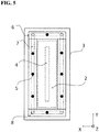
- FIG. 3 shows one gas introduction opening 8, the number is not particularly limited and, for example, in some embodiments, more than one gas introduction opening 8 may be provided. See, e.g., FIG. 5 described below.
- the gas supply passage 7 may be formed, e.g., by making, in the plate member 3, a through-hole extending in one direction, it is advantageous to use a technique as shown in FIGS. 4A and 4B .
- FIGS. 4A and 4B are schematic diagrams for explaining a technique of forming a gas supply passage of the plate member, according to an embodiment.
- a stepped concave-shaped groove 71 may be formed in a surface of the plate member 3, and a cover 6 may be installed onto plate member 3 to partially close an opening of the groove.
- the gas supply passage 7 is formed in the plate member 3, as depicted in FIG. 4B .
- the plate member 3 has one gas introduction opening 8.
- this configuration may, in some cases, lead to a situation where distribution of the amount of hydrogen gas supplied to the extraction electrode system E becomes uneven. In such a situation, a gas introduction ejection configuration depicted in FIG. 5 may be employed.
- FIG. 5 is a schematic X-Y plan view of another example of the gas introduction ejection configuration, according to an embodiment.
- a plurality of the gas introduction openings 8 and a plurality of the gas ejection openings 5 are formed in the plate member 3, and are arranged symmetrically laterally and vertically with respect to a center of the ion beam extracting hole 4. This configuration may be employed to eliminate the uneven distribution of the hydrogen gas supply amount.
- the plate member 3 having the symmetric gas introduction ejection configuration illustrated in FIG. 5 does not necessarily need to be employed.
- a plate member having a non-symmetric gas introduction ejection configuration may be employed, e.g., in a situation where it is advantageous to locally increase the hydrogen gas supply amount.
- FIG. 6 is a schematic X-Y plan view of yet another example of the gas introduction ejection configuration, according to an embodiment.
- a remaining region of the plate member 3 other than the protruding region may be partly used such that the gas ejection openings 5 are arranged at positions close to the ion beam extracting hole 4, and the gas supply passage 7 formed in the protruding region is branched into a plurality of sub-passages extending toward the ion beam extracting hole 4 to communicate with respective ones of the gas ejection openings 5.
- FIG. 7 is a schematic X-Y plan view of still another example of the gas introduction ejection configuration, according to an embodiment
- the plate member 3 may be configured such that two portions of the gas supply passage 7 are arranged, respectively, on sides of the ion beam extracting hole 4 to extend along a longitudinal axis of the ion beam extracting hole 4 (i.e., to extend in the Y direction in FIG. 6 ), and two or more gas ejection openings 5 provided in one of the portions of the gas supply passage 7 are arranged in a zigzag pattern with respect to two or more gas ejection openings 5 provided in the other portion of the gas supply passage 7.
- gas supply passage 7 need not be formed in the plate member 3 to surround the ion beam extracting hole 4, but may be formed with respect to only a part of the ion beam extracting hole 4.
- a plurality of gas supply passages 7 may be formed in the plate member 3 to surround only a part of the ion beam extracting hole 4.
- the plate member 3 has the protruding region PR provided with respect to the plasma generation chamber 2.
- the protruding region PR may be omitted from the plate member 3.
- the plate member 3 in terms of dimensional relationship in the X-Y plane, the plate member 3 may have a size equal to or less than that of the plasma generation chamber 2.
- FIG. 8 is a schematic top plan view of an example of a modification of the plate member, according to an embodiment.
- the plate member 3 has no protruding region. As seen in these examples, hydrogen gas may be introduced into the plate member 3 from one edge face of the plate member 3 facing in the X direction.
- the ion beam extracting hole 4 is formed in not only the plasma generation chamber 2 but also the plate member 3.
- the embodiments are not limited thereto.
- FIGS. 9A and 9B are, respectively, a schematic top plan view and a schematic X-Y plan view of another example of the modification of the plate member, according to an embodiment.
- the plasma generation chamber 2 may be configured such that a central region of one end thereof protrudes toward the extraction electrode system E, and the plate member 3 may be configured such that the plate member 3 is disposed to surround the protruding central region to have an external surface which is flush with that of the protruding central region.
- the ion beam extracting hole 4 may be omitted in the plate member 3.
- FIGS. 9A and 9B illustrate the gas supply passage 7 as a linear shape extending from the side facing the X-direction to the side facing the Z-direction.
- the embodiment is not limited thereto.
- the shape of the gas supply passage 7 it is possible to employ a curved shape as well as a linear shape or a cranked shape.
- the gas supply passage 7 does not need to be formed as a path parallel to the X or Z direction.
- the gas supply passage 7 may be formed to extend obliquely upwardly toward an ion beam extracting hole 4 of the extraction electrode system E.
- an abnormal electrical discharge between the plasma chamber 2 and the extraction electrode system E may occur due to a deposit formed around the ion beam extracting hole 4 of the extraction electrode system E.
- by supplying hydrogen gas toward the ion beam extracting hole 4 of the extraction electrode system E it becomes possible to effectively suppress the formation of a deposit around the ion beam extracting hole 4 of the extraction electrode system E.
- the gas supply passage 7 does not need to be formed to extend obliquely with respect to the X or Z direction.
- the gas supply passage 7 may be formed in a cranked shape to allow the gas ejection openings 5 to be arranged at positions opposed to the vicinity of the ion beam extracting hole 4 of the extraction electrode system E.
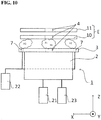
- hydrogen gas may be introduced into the plasma generation chamber 2, in addition to being introduced into the plate member 3. This example is depicted in FIG. 10 .
- FIG. 10 is a schematic top plan view of an example of a modification of the ion source in FIG. 2 , wherein hydrogen gas is additionally supplied to a plasma generation chamber, according to an embodiment.
- An ion source 1 depicted in FIG. 10 comprises a hydrogen gas supply source 23 for introducing hydrogen gas into the plasma generation chamber 2, in addition to the components of the ion source in FIG. 1 , a repeated description thereof being omitted for conciseness.
- a hydrogen gas supply source 23 for introducing hydrogen gas into the plasma generation chamber 2, in addition to the components of the ion source in FIG. 1 , a repeated description thereof being omitted for conciseness.
- a halogen-containing gas e.g., BF 3
- fluorine ions F+ and hydrogen ions H+ are released during ion beam extraction, as depicted in FIG. 10 .
- the fluorine ions may bind to hydrogen ions H 2 supplied from the gas supply passage 7 to suppress deposition of fluorides on the extraction electrode system E, deposition of fluorides on the extraction electrode system E may occur significantly, depending on the amount of fluorine ions at an area to which hydrogen gas is supplied or the amount of fluorine ions released from the plasma generation chamber 2.
- the supplied hydrogen gas may act on fluorides on the surface of the extraction electrode system E to remove the fluorides deposited on the extraction electrode system E.
- the halogen-containing material described in the above examples may be supplied from the dopant gas supply source directly to the plasma generation chamber 2 in the form of gas, or may be supplied to a vaporizer in the form of solid, and, after being vaporized through the vaporizer, supplied to the plasma generation chamber 2.
- Specific examples of the halogen-containing material may include BF 3 , PF 3 , AlI 3 and AlCl 3 .
- the shapes of the plasma generation chamber 2 and the plate member 3 are not particularly limited.
- the shapes may be, respectively, a rectangular parallelepiped shape and a rectangular tube, or a cylindrical shape and a disc shape.
- FIG. 10 depicts a configuration in which the halogen-containing gas and the hydrogen gas are supplied separately from the dopant gas supply source 21 and the hydrogen gas supply source 23. respectively.
- the gases may be mixed together prior to supply of the two gases to the plasma generation chamber 2, at a halfway point of a gas supply path, and the resulting mixed gas may be supplied to the plasma generation chamber 2.
- the hydrogen gas supply source 22 equipped in the ion source 1 of FIGS. 1-9B may be used to supply hydrogen gas to both the plasma generation chamber 2 and the plate member 3.
- hydrogen gas is supplied to the extraction electrode system E.
- hydrogen gas does not need to be supplied to all of the plurality of electrodes comprising the extraction electrode system E.
- a reaction product tends to more easily deposit on the suppression electrode 10 located at the nearest position with respect to the plasma generation chamber 2.
- hydrogen gas may be supplied only to the suppression electrode 10.
- the above embodiments have been described based on an example in which the plate member 3 is formed with a plurality of holes serving as the gas ejection openings 5.
- the plurality of holes may be combined as a single elongate hole.
- the plate member 3 and the plasma generation chamber 2 may be formed as separate components. Alternatively, the plate member 3 and the plasma generation chamber 2 may be integrally formed. Alternatively, the plate member 3 may be formed to additionally serve as a part of the plasma generation chamber 2.
- the plasma generation chamber 2 may be configured such that one end thereof facing the extraction electrode system E is formed as an open end, and this open end is closed by the plate member 3. In this way, the plate member 3 may additionally serve as one end wall of the plasma generation chamber 2 to reduce a component cost.
- an ionized halogen component reacts with the hydrogen gas supplied to the extraction electrode, before reacting with the extraction electrode, so that it is possible to suppress deposition of a reaction product on the extraction electrode. This suppression makes it possible to extend a period of time before cleaning the extraction electrode and thus realize long-term stable operation of the ion source.
- the plate member may be a wall of the plasma generation chamber.
- the plate member may be additionally used as a part of the wall of the plasma generation chamber, so that it is possible to reduce the number of components of the plasma generation chamber,
- the plate member may have a protruding region which protrudes with respect to the plasma chamber, when viewed from a direction along which the ion beam is extracted, and the hydrogen gas may be introduced into the protruding region.
- the gas supply passage may be easily formed in various configurations or patterns, using the protruding region.
- a part of the gas supply passage may be defined by a groove formed in the plate member, and a cover closing an opening of the groove.
- the extraction electrode may be formed with an ion beam extracting hole for extracting the ion beam therethrough, and the plate member may be configured to supply the hydrogen gas toward the hole.
- an abnormal electrical discharge between the plasma chamber and the extraction electrode may occur due to a deposit formed around the ion beam extracting hole of the extraction electrode.
- by supplying the hydrogen gas toward the ion beam extracting hole of the extraction electrode it becomes possible to effectively suppress the formation of a deposit around the ion beam extracting hole and thus suppress the occurrence of the abnormal electrical discharge.
- the plate member when the extraction electrode is formed with an ion beam-extracting elongate hole, the plate member may be formed with one or more hydrogen gas ejection openings along a longitudinal direction of the elongate hole.
- the ion source may comprise a supply source which supplies hydrogen gas into the plasma generation chamber.
- an ionized halogen component reacts with the hydrogen gas supplied to the extraction electrode, before reacting with the extraction electrode, so that it is possible to suppress deposition of a reaction product on the extraction electrode. This suppression makes it possible to extend a period of time before cleaning the extraction electrode and thus realize long-term stable operation of the ion source
Landscapes
- Chemical & Material Sciences (AREA)
- Engineering & Computer Science (AREA)
- Combustion & Propulsion (AREA)
- Physics & Mathematics (AREA)
- Optics & Photonics (AREA)
- Analytical Chemistry (AREA)
- Electron Sources, Ion Sources (AREA)
- Plasma Technology (AREA)
Applications Claiming Priority (2)
| Application Number | Priority Date | Filing Date | Title |
|---|---|---|---|
| JP2018201465A JP2020068161A (ja) | 2018-10-26 | 2018-10-26 | イオン源 |
| US16/353,475 US10600608B1 (en) | 2018-10-26 | 2019-03-14 | Ion source |
Publications (2)
| Publication Number | Publication Date |
|---|---|
| EP3657526A2 true EP3657526A2 (de) | 2020-05-27 |
| EP3657526A3 EP3657526A3 (de) | 2020-10-07 |
Family
ID=69902677
Family Applications (1)
| Application Number | Title | Priority Date | Filing Date |
|---|---|---|---|
| EP19193653.3A Withdrawn EP3657526A3 (de) | 2018-10-26 | 2019-08-26 | Ionenquelle mit wasserstoffgaszufuhr zur extraktionselektrode |
Country Status (3)
| Country | Link |
|---|---|
| US (1) | US10600608B1 (de) |
| EP (1) | EP3657526A3 (de) |
| JP (1) | JP2020068161A (de) |
Cited By (1)
| Publication number | Priority date | Publication date | Assignee | Title |
|---|---|---|---|---|
| WO2023076007A1 (en) * | 2021-10-28 | 2023-05-04 | Applied Materials, Inc. | Ion source gas injection beam shaping |
Families Citing this family (2)
| Publication number | Priority date | Publication date | Assignee | Title |
|---|---|---|---|---|
| US20220013323A1 (en) * | 2020-07-10 | 2022-01-13 | Axcelis Technologies, Inc. | Hydrogen co-gas when using a chlorine-based ion source material |
| CN112271145A (zh) * | 2020-09-25 | 2021-01-26 | 华东光电集成器件研究所 | 一种注入机离子源弧室的底板 |
Citations (1)
| Publication number | Priority date | Publication date | Assignee | Title |
|---|---|---|---|---|
| JP2016177870A (ja) | 2015-03-18 | 2016-10-06 | 株式会社アルバック | イオンビーム装置、イオン注入装置、イオンビーム放出方法 |
Family Cites Families (7)
| Publication number | Priority date | Publication date | Assignee | Title |
|---|---|---|---|---|
| US4559477A (en) * | 1983-11-10 | 1985-12-17 | The United States Of America As Represented By The United States Department Of Energy | Three chamber negative ion source |
| JP4328067B2 (ja) * | 2002-07-31 | 2009-09-09 | アプライド マテリアルズ インコーポレイテッド | イオン注入方法及びsoiウエハの製造方法、並びにイオン注入装置 |
| US7488958B2 (en) * | 2005-03-08 | 2009-02-10 | Axcelis Technologies, Inc. | High conductance ion source |
| US10304665B2 (en) * | 2011-09-07 | 2019-05-28 | Nano-Product Engineering, LLC | Reactors for plasma-assisted processes and associated methods |
| JP6177123B2 (ja) * | 2013-12-25 | 2017-08-09 | 住友重機械イオンテクノロジー株式会社 | 支持構造およびそれを用いたイオン発生装置 |
| US20150380526A1 (en) * | 2014-06-27 | 2015-12-31 | Applied Materials, Inc. | Methods for forming fin structures with desired dimensions for 3d structure semiconductor applications |
| JP6415388B2 (ja) * | 2015-05-29 | 2018-10-31 | 住友重機械イオンテクノロジー株式会社 | プラズマ生成装置 |
-
2018
- 2018-10-26 JP JP2018201465A patent/JP2020068161A/ja active Pending
-
2019
- 2019-03-14 US US16/353,475 patent/US10600608B1/en active Active
- 2019-08-26 EP EP19193653.3A patent/EP3657526A3/de not_active Withdrawn
Patent Citations (1)
| Publication number | Priority date | Publication date | Assignee | Title |
|---|---|---|---|---|
| JP2016177870A (ja) | 2015-03-18 | 2016-10-06 | 株式会社アルバック | イオンビーム装置、イオン注入装置、イオンビーム放出方法 |
Cited By (3)
| Publication number | Priority date | Publication date | Assignee | Title |
|---|---|---|---|---|
| WO2023076007A1 (en) * | 2021-10-28 | 2023-05-04 | Applied Materials, Inc. | Ion source gas injection beam shaping |
| US11769648B2 (en) | 2021-10-28 | 2023-09-26 | Applied Materials, Inc. | Ion source gas injection beam shaping |
| TWI844991B (zh) * | 2021-10-28 | 2024-06-11 | 美商應用材料股份有限公司 | 離子源及離子植入系統 |
Also Published As
| Publication number | Publication date |
|---|---|
| US10600608B1 (en) | 2020-03-24 |
| EP3657526A3 (de) | 2020-10-07 |
| JP2020068161A (ja) | 2020-04-30 |
Similar Documents
| Publication | Publication Date | Title |
|---|---|---|
| US10600608B1 (en) | Ion source | |
| US8796131B2 (en) | Ion implantation system and method | |
| JP7588254B2 (ja) | 半導体プロセスデバイスにおける載置装置及び半導体プロセスデバイス | |
| CN105340049B (zh) | 离子源及其操作方法 | |
| KR20140106417A (ko) | 플라즈마 처리 장치 | |
| TWI744747B (zh) | 真空處理設備及用於真空電漿處理至少一個基板或用於製造基板的方法 | |
| TW201616542A (zh) | 射束引出狹縫構造及離子源 | |
| EP3307030B1 (de) | Plasmaerzeugungsvorrichtung | |
| KR102208864B1 (ko) | 지지구조 및 이를 이용한 이온발생장치 | |
| CN111710584A (zh) | 离子生成装置及离子注入装置 | |
| US10892137B2 (en) | Ion implantation processes and apparatus using gallium | |
| EP3609302A1 (de) | Plasmaerzeugungsvorrichtung | |
| KR20150140384A (ko) | 성막 장치 및 성막 방법 | |
| KR20020079738A (ko) | 전기전도성 벽을 갖춘 플라즈마 처리장치 | |
| KR102892631B1 (ko) | 플라즈마 발생 장치, 및 상기 플라즈마 발생 장치를 포함하는 배기 가스 처리 장치 | |
| WO2025200335A1 (zh) | 射频等离子装置及真空系统 | |
| CN115985754B (zh) | 离子源 | |
| KR102193380B1 (ko) | 기판 처리 장치 | |
| KR20170113722A (ko) | 높은 공간 선택성을 가지는 선형 플라즈마 발생 장치 | |
| US10573490B2 (en) | Ion source and ion implantation apparatus | |
| CN116732504A (zh) | 屏蔽结构、喷淋头以及等离子体设备 | |
| US9657389B2 (en) | Target for spark vaporization with physical limiting of the propagation of the spark | |
| CN105489463A (zh) | 预清洗腔室及半导体加工设备 | |
| KR20260069592A (ko) | 패턴화된 증착을 위한 플라즈마 소스 | |
| JPS60195854A (ja) | イオン源 |
Legal Events
| Date | Code | Title | Description |
|---|---|---|---|
| PUAI | Public reference made under article 153(3) epc to a published international application that has entered the european phase |
Free format text: ORIGINAL CODE: 0009012 |
|
| STAA | Information on the status of an ep patent application or granted ep patent |
Free format text: STATUS: THE APPLICATION HAS BEEN PUBLISHED |
|
| AK | Designated contracting states |
Kind code of ref document: A2 Designated state(s): AL AT BE BG CH CY CZ DE DK EE ES FI FR GB GR HR HU IE IS IT LI LT LU LV MC MK MT NL NO PL PT RO RS SE SI SK SM TR |
|
| AX | Request for extension of the european patent |
Extension state: BA ME |
|
| RIC1 | Information provided on ipc code assigned before grant |
Ipc: H01J 27/02 20060101ALI20200602BHEP Ipc: H01J 37/08 20060101AFI20200602BHEP Ipc: H01J 27/22 20060101ALI20200602BHEP |
|
| PUAL | Search report despatched |
Free format text: ORIGINAL CODE: 0009013 |
|
| AK | Designated contracting states |
Kind code of ref document: A3 Designated state(s): AL AT BE BG CH CY CZ DE DK EE ES FI FR GB GR HR HU IE IS IT LI LT LU LV MC MK MT NL NO PL PT RO RS SE SI SK SM TR |
|
| AX | Request for extension of the european patent |
Extension state: BA ME |
|
| RIC1 | Information provided on ipc code assigned before grant |
Ipc: H01J 27/02 20060101ALI20200903BHEP Ipc: H01J 37/08 20060101AFI20200903BHEP Ipc: H01J 27/22 20060101ALI20200903BHEP |
|
| STAA | Information on the status of an ep patent application or granted ep patent |
Free format text: STATUS: REQUEST FOR EXAMINATION WAS MADE |
|
| 17P | Request for examination filed |
Effective date: 20210302 |
|
| RBV | Designated contracting states (corrected) |
Designated state(s): AL AT BE BG CH CY CZ DE DK EE ES FI FR GB GR HR HU IE IS IT LI LT LU LV MC MK MT NL NO PL PT RO RS SE SI SK SM TR |
|
| STAA | Information on the status of an ep patent application or granted ep patent |
Free format text: STATUS: EXAMINATION IS IN PROGRESS |
|
| 17Q | First examination report despatched |
Effective date: 20240906 |
|
| STAA | Information on the status of an ep patent application or granted ep patent |
Free format text: STATUS: THE APPLICATION IS DEEMED TO BE WITHDRAWN |
|
| 18D | Application deemed to be withdrawn |
Effective date: 20250108 |