EP3657449A1 - Paper money handling device - Google Patents
Paper money handling device Download PDFInfo
- Publication number
- EP3657449A1 EP3657449A1 EP17918078.1A EP17918078A EP3657449A1 EP 3657449 A1 EP3657449 A1 EP 3657449A1 EP 17918078 A EP17918078 A EP 17918078A EP 3657449 A1 EP3657449 A1 EP 3657449A1
- Authority
- EP
- European Patent Office
- Prior art keywords
- paper money
- unit
- dispensed
- pressing
- take
- Prior art date
- Legal status (The legal status is an assumption and is not a legal conclusion. Google has not performed a legal analysis and makes no representation as to the accuracy of the status listed.)
- Withdrawn
Links
- 238000003825 pressing Methods 0.000 claims abstract description 116
- 238000001514 detection method Methods 0.000 claims abstract description 66
- 230000005540 biological transmission Effects 0.000 claims description 14
- 230000007246 mechanism Effects 0.000 claims description 12
- 238000010586 diagram Methods 0.000 description 12
- 238000000034 method Methods 0.000 description 4
- 230000008569 process Effects 0.000 description 2
- 230000008901 benefit Effects 0.000 description 1
- 230000000903 blocking effect Effects 0.000 description 1
- 230000000052 comparative effect Effects 0.000 description 1
- 230000000694 effects Effects 0.000 description 1
- 230000006870 function Effects 0.000 description 1
- 238000003384 imaging method Methods 0.000 description 1
- 238000012986 modification Methods 0.000 description 1
- 230000004048 modification Effects 0.000 description 1
Images






Classifications
-
- G—PHYSICS
- G07—CHECKING-DEVICES
- G07D—HANDLING OF COINS OR VALUABLE PAPERS, e.g. TESTING, SORTING BY DENOMINATIONS, COUNTING, DISPENSING, CHANGING OR DEPOSITING
- G07D11/00—Devices accepting coins; Devices accepting, dispensing, sorting or counting valuable papers
- G07D11/10—Mechanical details
- G07D11/14—Inlet or outlet ports
-
- B—PERFORMING OPERATIONS; TRANSPORTING
- B65—CONVEYING; PACKING; STORING; HANDLING THIN OR FILAMENTARY MATERIAL
- B65H—HANDLING THIN OR FILAMENTARY MATERIAL, e.g. SHEETS, WEBS, CABLES
- B65H3/00—Separating articles from piles
- B65H3/34—Article-retaining devices controlling the release of the articles to the separators
-
- B—PERFORMING OPERATIONS; TRANSPORTING
- B65—CONVEYING; PACKING; STORING; HANDLING THIN OR FILAMENTARY MATERIAL
- B65H—HANDLING THIN OR FILAMENTARY MATERIAL, e.g. SHEETS, WEBS, CABLES
- B65H31/00—Pile receivers
- B65H31/26—Auxiliary devices for retaining articles in the pile
-
- B—PERFORMING OPERATIONS; TRANSPORTING
- B65—CONVEYING; PACKING; STORING; HANDLING THIN OR FILAMENTARY MATERIAL
- B65H—HANDLING THIN OR FILAMENTARY MATERIAL, e.g. SHEETS, WEBS, CABLES
- B65H7/00—Controlling article feeding, separating, pile-advancing, or associated apparatus, to take account of incorrect feeding, absence of articles, or presence of faulty articles
- B65H7/02—Controlling article feeding, separating, pile-advancing, or associated apparatus, to take account of incorrect feeding, absence of articles, or presence of faulty articles by feelers or detectors
-
- G—PHYSICS
- G07—CHECKING-DEVICES
- G07D—HANDLING OF COINS OR VALUABLE PAPERS, e.g. TESTING, SORTING BY DENOMINATIONS, COUNTING, DISPENSING, CHANGING OR DEPOSITING
- G07D11/00—Devices accepting coins; Devices accepting, dispensing, sorting or counting valuable papers
- G07D11/10—Mechanical details
- G07D11/12—Containers for valuable papers
- G07D11/13—Containers for valuable papers with internal means for handling valuable papers
-
- G—PHYSICS
- G07—CHECKING-DEVICES
- G07D—HANDLING OF COINS OR VALUABLE PAPERS, e.g. TESTING, SORTING BY DENOMINATIONS, COUNTING, DISPENSING, CHANGING OR DEPOSITING
- G07D11/00—Devices accepting coins; Devices accepting, dispensing, sorting or counting valuable papers
- G07D11/20—Controlling or monitoring the operation of devices; Data handling
- G07D11/22—Means for sensing or detection
- G07D11/235—Means for sensing or detection for monitoring or indicating operating conditions; for detecting malfunctions
-
- G—PHYSICS
- G07—CHECKING-DEVICES
- G07D—HANDLING OF COINS OR VALUABLE PAPERS, e.g. TESTING, SORTING BY DENOMINATIONS, COUNTING, DISPENSING, CHANGING OR DEPOSITING
- G07D11/00—Devices accepting coins; Devices accepting, dispensing, sorting or counting valuable papers
- G07D11/40—Device architecture, e.g. modular construction
-
- B—PERFORMING OPERATIONS; TRANSPORTING
- B65—CONVEYING; PACKING; STORING; HANDLING THIN OR FILAMENTARY MATERIAL
- B65H—HANDLING THIN OR FILAMENTARY MATERIAL, e.g. SHEETS, WEBS, CABLES
- B65H2515/00—Physical entities not provided for in groups B65H2511/00 or B65H2513/00
- B65H2515/30—Forces; Stresses
- B65H2515/34—Pressure, e.g. fluid pressure
-
- B—PERFORMING OPERATIONS; TRANSPORTING
- B65—CONVEYING; PACKING; STORING; HANDLING THIN OR FILAMENTARY MATERIAL
- B65H—HANDLING THIN OR FILAMENTARY MATERIAL, e.g. SHEETS, WEBS, CABLES
- B65H2701/00—Handled material; Storage means
- B65H2701/10—Handled articles or webs
- B65H2701/19—Specific article or web
- B65H2701/1912—Banknotes, bills and cheques or the like
-
- G—PHYSICS
- G07—CHECKING-DEVICES
- G07D—HANDLING OF COINS OR VALUABLE PAPERS, e.g. TESTING, SORTING BY DENOMINATIONS, COUNTING, DISPENSING, CHANGING OR DEPOSITING
- G07D11/00—Devices accepting coins; Devices accepting, dispensing, sorting or counting valuable papers
- G07D11/20—Controlling or monitoring the operation of devices; Data handling
- G07D11/32—Record keeping
- G07D11/34—Monitoring the contents of devices, e.g. the number of stored valuable papers
-
- G—PHYSICS
- G07—CHECKING-DEVICES
- G07D—HANDLING OF COINS OR VALUABLE PAPERS, e.g. TESTING, SORTING BY DENOMINATIONS, COUNTING, DISPENSING, CHANGING OR DEPOSITING
- G07D2211/00—Paper-money handling devices
Definitions
- the present invention relates to a paper money handling apparatus that takes in paper money remaining in a dispenser unit.
- a method that has been proposed includes clamping paper money remaining in a paper money slot with a belt conveyer, opening a gate that makes/breaks a communicating state between the paper money slot and a left-money collection box, and taking the remaining paper money into the left-money collection box by the belt conveyer (see Patent Document 1 as an example).
- Paper money dispensed to a dispenser unit may be a few pieces of paper money or may be a bundle of several ten pieces of paper money.
- Paper money is taken into an apparatus by clamping the paper money by a belt conveyer as described above, with a setting of strong clamping force suitable for a few pieces of paper money, for example, a malfunctioning take-in operation may occur or the paper money may be damaged due to a load to carry the paper money generated as a clamping force becomes stronger particularly for a bundle of several ten pieces of paper money.
- the present invention was made in view of the above point, and it is an object of the present invention to provide a paper money handling apparatus that can control occurrence of a malfunctioning take-in operation of paper money remaining in a dispenser unit.
- a paper money handling apparatus includes a dispenser unit to dispense paper money, a pressing unit to move between a pressing position at which the pressing unit presses dispensed paper money that is the paper money dispensed to the dispenser unit and a retraction position to which the pressing unit is retracted from the pressing position, a drive unit to move the pressing unit, a placement unit on which at least one portion of the dispensed paper money is placed, a clamp detection sensor to detect that the dispensed paper money is clamped between the pressing unit and the placement unit, a take-in carrier to take the dispensed paper money in an interior of the apparatus, a paper money detection sensor to detect presence or absence of the dispensed paper money, and a controller to control the drive unit to cause the pressing unit to move to the pressing position when the dispensed paper money being remaining is detected by the paper money detection sensor, and the controller controls the take-in carrier to take the dispensed paper money in the interior of the apparatus when the clamp detection sensor detects the dispense
- occurrence of a malfunctioning take-in operation of paper money remaining in a dispenser unit can be controlled.
- FIG. 1 is a left side view of a paper money handling apparatus 1.
- FIG. 1 a front-to-rear direction, a left-to-right direction, and an up-to-down direction are indicated in FIG. 1 , and also in FIG. 4 , FIG. 5A to FIG. 5C and FIG. 6A to FIG. 6E , which are described later.
- the paper money handling apparatus 1 includes a top module M1, a take-in and recycle module M2, recycle modules M3 and M4, a supplementary module M5, and a collection module M6 in this order from the top.
- the top module M1 has a deposit unit 83 for receiving paper money B (see FIG. 5A ) and a dispenser unit 10 for dispensing the paper money B, both of which are provided in a front edge that is projected toward the front.
- the top module M1 also has a DC motor 84 that causes a take-in carrier 60, which is described later, to operate.
- the DC motor 84 is, for example, a drive source for carrier that can be used for carrying the paper money B in addition to a take-in operation of the dispensed paper money B1.
- the top module M1 has a discrimination unit that discriminates the paper money B received from the deposit unit 83 and a carrier unit that carries the paper money B.
- the take-in and recycle module M2 and the recycle modules M3 and M4 have paper money containment units M2a, M2b, M3a, M3b, M4a, and M4b, each being arranged in the front portion or the rear portion of respective modules, and also have a carrier unit that carries the paper money B.
- the take-in and recycle module M2 and the recycle modules M3 and M4 are an example of plural containment modules that are layered under the top module M1.
- the housing, the I/O board, and the paper money containment unit M3b or M4b located in the rear portion of the recycle module M3 or M4 can be used for the take-in and recycle module M2, and in that case, instead of the paper money containment unit M3a or M4a located in the front portion, the paper money containment unit M2a for containing dispensed paper money B1 that remains unretrieved and the other components may be arranged.
- the take-in carrier 60 illustrated in FIG. 5A to FIG. 5C takes the dispensed paper money B1 into the paper money containment unit M2a located in the front portion of the take-in and recycle module M2 that is located on the top of the above-described containment modules.
- the paper money containment unit M2a can contain 100 pieces of dispensed paper money B1.
- the paper money handling apparatus 1 records paper money serial numbers of paper money B to be dispensed, when the dispensed paper money B1 to be taken in is illicitly retrieved by a customer during a take-in operation, the dispensed paper money B1 that was illicitly retrieved can be identified from the paper money serial numbers.
- the paper money containment unit M2a contains stacked dispensed paper money B1 and other paper money containment units M2b, M3a, M3b, M4a, and M4b contain the paper money B wrapped with a film.
- the film-wrapped paper money B is recycled for dispensing.
- the dispensed paper money B1 that is taken in from the dispensing unit 10 is not always contained in the paper money containment unit M2a, but may be contained in other paper money containment units M2b, M3a, M3b, M4a, and M4b to be recycled for dispensing, or may be contained in the collection module M6 described later.
- the paper money containment unit M2b located in the rear portion is not provided in the take-in and recycle module M22
- by taking advantage of the space dispensed paper money B1 in a larger size can be retrieved, or the number of pieces of the dispensed paper money B1 retrieved can be increased.
- the supplementary module M5 contains paper money B used for dispensing.
- the collection module M6 contains paper money B that is not recycled from among paper money B deposited.
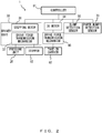
- FIG. 2 is a block diagram illustrating a schematic configuration of the paper money handling apparatus 1.
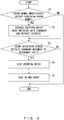
- FIG. 3 is a flowchart that explains a take-in operation of the dispensed paper money B1.
- FIG. 4 is a right side view illustrating the top module M1 and the take-in and recycle module M2.
- FIG. 5A to FIG. 5C are explanatory diagrams that explain an overview of the take-in operation of the dispensed paper money B1.
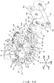
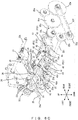
- FIG. 6A to FIG. 6E are explanatory diagrams that explain details of the take-in operation of the dispensed paper money B1.
- the paper money handling apparatus 1 includes a dispenser unit 10, a pressing unit 20, a drive unit 30, a placement unit 40, a clamp detection sensor 50, a take-in carrier 60, a paper money detection sensor 70, and a controller 81.
- the paper money handling apparatus 1 may also include a stopper 82, a deposit unit 83, a DC motor 84, and a drive force transmission mechanism 85.
- the controller 81 moves the pressing unit 20 to a pressing position P11 (see FIG. 5C and FIG. 6E ) and controls a stepping motor 31 to move the stopper 82 to a retraction position P32 (see FIG. 6C to FIG. 6E ), and more details are explained later.
- the controller 81 stops the operation of the stepping motor 31 and controls the take-in carrier 60 (the DC motor 84) so as to take the dispensed paper money B1 into the paper money containment unit M2a (see FIG. 1 and FIG. 5A to FIG. 5C ).
- the pressing unit 20 has a first arm 21, a connecting shaft 22, a second arm 23, a torsion spring 24, a hold member 25, and a roller 26.
- the pressing unit 20 moves between a pressing position P11 (see FIG. 5C and FIG. 6E ) at which the pressing unit 20 presses dispensed paper money B1 (see FIG. 5B ) and a retraction position P12 (see FIG. 5A and FIG. 6A ) to which the pressing unit 20 is retracted from the pressing position P11.
- the configuration of the pressing unit 20 is merely a preferable example, and other configurations may be used as long as the pressing unit 20 moves between the pressing position P11 at which the pressing unit 20 presses the dispensed paper money B1 and the retraction position P12 to which the pressing unit 20 is retracted from the pressing position P11.
- one end of the first arm 21 is fixed at a rotary shaft 32k of the drive force transmission mechanism 32 that is rotated by the operation of the drive unit 30.
- the connecting shaft 22 is provided at another end of the first arm 21.
- the second arm 23 and the hold member 25 are connected to the connecting shaft 22 on each of two sides of a connecting portion at which the connecting shaft 22 and the first arm 21 are connected to each other. Note that two second arms 23 and two hold members 25 are connected to the connecting shaft 22, but the number of the second arms 23 and that of the hold members 25 may be one or may be three or more.
- the second arm 23 has a roller 23a that is a bearing, for example, at a free end that is an end opposite to the end connected to the connecting shaft 22.
- the second arm 23 is biased downward by the torsion spring 24, which is an example of an elastic body, so that a side of the roller 23a (the free end) becomes closer to the dispensed paper money B1.
- the torsion spring 24 with one end fixed on the first arm 21 is wound around the connecting shaft 22.
- the second arm 23 is biased toward a side of the dispensed paper money B1 by a biasing force of the torsion spring 24.
- the roller 23a of the second arm 23 is the first portion of the pressing unit 20 to contact with the dispensed paper money B1 as illustrated in FIG. 6C .
- the second arm 23 has a guide unit 23b provided to project toward the side of the dispensed paper money B1 so as to be able to contact with the dispensed paper money B1.
- two projections 23c and 23c are provided at an end opposite to the side on which the roller 23a is provided.
- the projections 23c and 23c contact with a leaf spring provided on an immovably-fixed member in the top module M1 or the take-in and recycle module M2 and are biased downward when the pressing unit 20 is at the retraction position P12 as illustrated in FIG. 6A .
- the second arm 23 rotates upward (anticlockwise in FIG. 6A ) from the side of the roller 23a against the biasing force of the torsion spring 24 and the second arm 23 becomes more parallel to the first arm 21.
- the hold member 25 has a long plate-like shape and one end is rotatably connected to the connecting shaft 22.
- the hold member 25 is arranged to drop forward by self-weight, for example, and holds the dispensed paper money B1 from a stage prior to the dispensed paper money B1 being dispensed to the dispenser unit 10.
- the tip that is a free end of the hold member 25 has a tip bend 25a that is bent so that a plane of the tip contacting with the dispensed paper money B1 is parallel to the dispensed paper money B1.
- the hold member 25 preferably holds the dispensed paper money B1 at least when the pressing unit 20 is at the retraction position P12, but also holds the dispensed paper money B1 when the pressing unit 20 is at the pressing position P11. Note that illustration of the hold member 25 is omitted in FIG. 5B and FIG. 5C .
- the roller 26 is provided at the center of the connecting shaft 22 in the left-to-right direction, and when the pressing unit 20 moves to the pressing position P11, the roller 26 comes into contact with a roller 41 around which a carrier belt 61 of the take-in carrier 60 is wound having the dispensed paper money B1 and the carrier belt 61 in between.
- the drive unit 30 has a stepping motor 31 that is an example of a drive source arranged in the take-in and recycle module M2 and a drive force transmission mechanism 32 that transmits the drive force of the stepping motor 31 to each of the pressing unit 20 and the stopper 82.
- the drive force transmission mechanism 32 has gears 32a, 32c, 32d, 32e, 32g, and 32h and transmission belts 32b and 32f that are arranged on the right side of the paper money handling apparatus 1, and the drive force transmitted by these components is transmitted toward the left side of the paper money handling apparatus 1 via a rotary shaft 32i illustrated in FIG. 6A to FIG. 6E .
- the drive force is transmitted via a gear train 32j to a rotary shaft 32k that rotates the first arm 21 of the pressing unit 20 and a rotary shaft 32L that rotates the stopper 82.
- separate drive units 30 may be arranged for moving the pressing unit 20 and for moving the stopper 82, but as described above, by means of a configuration in which the drive force generated by a single drive source (stepping motor 31) is transmitted to both the pressing unit 20 and the stopper 82 by the drive force transmission mechanism 32, the number of drive sources can be reduced and as a result, the paper money handling apparatus 1 can be simplified.
- the placement unit 40 has a roller 41, a plate 42, a projection for detection 43, and left- and right-side walls 44 and 45 and moves down from a first position P21 illustrated in FIG. 6A to FIG. 6D to a second position P22 illustrated in FIG. 6E when the placement unit 40 is pressed by the pressing unit 20 with the dispensed paper money B1 in between.
- the placement unit 40 is biased upward to the first position P21 by an elastic body that is not illustrated in the drawings. For that reason, the placement unit 40 is at the first position P21 in a state of not being pressed by the pressing unit 20, and when the placement unit 40 is pressed by the pressing unit 20 against the bias force of the elastic body, the placement unit 40 moves down to the second position P22. Note that in the downward movement of the placement unit 40, only the front side of the placement unit 40 is moved down in a rotary movement, but the entirety of the placement unit 40 may be moved down.
- the plate 42 has grooves and holes to avoid interference from the carrier belt 61 or the stopper 82. As illustrated in FIG. 5B , a portion on the rear side of the dispensed paper money B1 is placed on the plate 42. Note that the paper money B dispensed to the dispenser unit 10 is carried forward in the top module M1 and is also carried obliquely upward along the placement unit 40 to the dispenser unit 10. Then the front side of the paper money B is placed on the bottom of the dispenser unit 10 and the rear side is placed on the plate 42.
- two semicircular cutouts 42a and 42a are provided on the front edge of the plate 42.
- a pair of prisms which is not illustrated, is arranged under the cutouts 42a and 42a.
- One of the cutouts 42a and 42a passes through paper money detection light L1 (illustrated by a dash-dot-dash line in FIG. 6A ) that is emitted downward from the paper money detection sensor 70 in FIG. 2 , and another one passes through the paper money detection light L1 traveling upward to the paper money detection sensor 70 after the paper money detection light L1 is bent at the pair of prisms.
- the detection of the dispensed paper money B1 by means of the paper money detection sensor 70 is not limited to the detection by using the paper money detection light L1 that passes through the cutout 42a, but any detection can be used as long as the presence/absence of the dispensed paper money B1 can be detected, and a position of the detection is not limited in particular.
- the projection for detection 43 projecting downward is provided at the front edge of the plate 42. As illustrated in FIG. 6E , this projection for detection 43 blocks clamp detection light L2 (illustrated by a bold line in FIG. 6E ) of the clamp detection sensor 50 that is a light blocking sensor illustrated in FIG. 2 and FIG. 5A to FIG. 5C , only when the placement unit 40 is moved down to the second position P22. Note that a projection for detection 43-1 illustrated by a dash-dot-dot-dash line in FIG. 6E that is a projection for detection when the placement unit 40 is at the first position P21 does not block the clamp detection light L2.
- the clamp detection sensor 50 is not limited to a sensor that detects the clamp detection light L2 being blocked by the projection for detection 43, but may be other sensors as long as the sensor can detect that the placement unit 40 is moved down to the second position P22. Moreover, the clamp detection sensor 50 may be any sensor as long as the sensor can detect the dispensed paper money B1 being clamped between the pressing unit 20 and the placement unit 40. When the pressing unit 20 is provided so that a portion of the pressing unit 20 contacting with the dispensed paper money B1 moves up and down and is biased downward, the clamp detection sensor 50 may be a sensor detecting that this contacting portion moves upward at the time of pressing the dispensed paper money B1.
- the clamp detection sensor 50 may be a sensor detecting a load imposed on the pressing unit 20 at the time of pressing the dispensed paper money B1.
- the placement unit 40 therefore is not limited to a unit that moves down from the first position P21 to the second position P22, but may be immovably fixed in the take-in and recycle module M2.
- the side walls 44 and 45 are provided so as to project upward on the left and right sides of the plate 42 and guide the side faces of the paper money B carried from the top module M1 to the dispenser unit 10 and the dispensed paper money B1 taken into the paper money containment unit M2a by the take-in carrier 60.
- the take-in carrier 60 takes the dispensed paper money B1 into the paper money containment unit M2a by using the above-described carrier belt 61 and a bladed wheel 62.
- the controller 81 has, for example, a processor (e.g., CPU: Central Processing Unit) that functions as an arithmetic processing unit controlling the operations of the entirety of the paper money handling device 1 and a storage unit such as a memory.
- a processor e.g., CPU: Central Processing Unit
- a storage unit such as a memory.
- the controller 81 controls the drive unit 30 to cause the pressing unit 20 to move to the pressing unit P21 and to cause the stopper 82 to move to the retraction position P32.
- the controller 81 controls the take-in carrier 60 to take the dispensed paper money B1 into the paper money containment unit M2a.
- the controller 81 controls the take-in carrier 60, for example, by operating the DC motor 84 and transmitting the drive force generated by the DC motor 84 to the take-in carrier 60 via the drive force transmission mechanism 85.
- the stopper 82 moves between a control position P31 illustrated in FIG. 5A and FIG. 6A that controls a position of a rear edge on a side of the interior of the apparatus (the paper money containment unit M2a) of the dispensed paper money B1 and a retraction position P32 illustrated in FIG. 6C to FIG. 6E to which the stopper 82 is retracted from the control position P31.
- the stopper 82 rotates together with a rotary shaft 32L by the drive force of the stepping motor 31 transmitted via the drive force transmission mechanism 32. Note that after the stopper 82 fell down to the retraction position P32 as illustrated in FIG.
- the stopper 82 is in contact with other members, and when this load is detected by a torque limiter provided on the rotary shaft 32L, only the rotation of the rotary shaft 32L may be stopped during the rotation of the pressing unit 20 (the first arm 21). Alternatively, the rotation of the rotary shaft 32L may not be stopped after the stopper 82 fell down to the retraction position P32 when there is a space where the rotary shaft 32L can keep rotating. Note that when the stopper 82 falls down to the retraction position P32, the dispensed paper money B1 may be clamped between at least a portion of the pressing unit 20 (the roller 23a of the second arm 23) and the placement unit 40 as illustrated in FIG. 6C .
- the deposit unit 83 is provided above the dispenser unit 10 as illustrated in FIG. 5A .
- Paper money B is inserted into the top module M1 while being guided by the top face of the dispenser unit 10.
- the paper money B is carried to the paper money containment unit M2b, M3a, M3b, M4a, or M4b of the take-in and recycle module M2, or the recycle modules M3 and M4, or the collection module M6 as illustrated in FIG. 1 , after going through the discrimination unit in the top module M1.
- the drive force generated by the DC motor 84 illustrated in FIG. 1 and FIG. 2 is transmitted to the carrier belt 61 via the drive force transmission mechanism 85 that has gears 85a and 85b and the rotary shaft 85c illustrated in FIG. 6A to FIG. 6E .
- the controller 81 detects remaining (unretrieved) dispensed paper money B1 by means of the paper money detection sensor 70 (step S1).
- the controller 81 determines dispensed paper money B1 to be remaining, for example, by determining whether the dispensed paper money B1 remains in the dispenser unit 10 after a certain period of time has elapsed since paper money B was dispensed to the dispenser unit 10 or not. Alternatively, the controller 81 may determine dispensed paper money B1 to be remaining by determining whether the dispensed paper money B1 remains in the dispenser unit 10 or not when a customer moves away from the paper money handling apparatus 1 based on an image captured by an imaging device of the paper money handling apparatus 1 or a detection result of a human detecting sensor.
- step S1 NO
- the processing in FIG. 3 is ended.
- step S1 determines the dispensed paper money B1 to be remaining (step S1: YES)
- the controller 81 controls the stepping motor 31 (the drive unit 30) to cause the pressing unit 20 to move to the pressing position P11 (see FIG. 5C and FIG. 6E ) and to cause the stopper 82 to move to the retraction position P32 (step S2).
- the controller 81 causes the clamp detection sensor 50 to detect whether the placement unit 40 is pressed by the pressing unit 20 with the dispensed paper money B1 in between and is moved down from the pressing position P11 to the second position P22 or not and repeats the detection until the downward movement of the placement unit 40 is detected.
- step S3 When the downward movement of the placement unit 40 is detected (step S3: YES), the controller unit 81 stops the operation of the stepping motor 31 (step S4) and controls the take-in carrier 60 (the DC motor 84) to take the dispensed paper money B1 in the paper money containment unit M2a (step S5).
- the controller 81 may repeat the processing from the processing in step S2, or more specifically, the processing of operating the stepping motor 31 (the drive unit 30).
- step S4 After the downward movement of the placement unit 40 is detected again (step S3: YES), the controller 81 may stop the operation of the stepping motor 31 (step S4) and may resume taking in and carrying (step S5). In this case, although the operation of the stepping motor 31 is resumed, the stopper 82 has already fallen down to the retraction position P32. Then, as described above, the stopper 82 is in contact with other members, and when this load is detected by a torque limiter etc. provided on the rotary shaft 32L, only the rotation of the rotary shaft 32L may be stopped even though the pressing unit 20 is moving to the pressing position P11.
- the controller 81 operates the stepping motor 31, moves the pressing unit 20 to the retraction position P12, and moves the stopper 82 to the control position P31.
- the controller 81 stops the stepping motor 31.
- the paper money handling apparatus 1 includes a dispenser unit 10, a pressing unit 20, a drive unit 30, a placement unit 40, a clamp detection sensor 50, a take-in carrier 60, a paper money detection sensor 70, and a controller 81.
- the dispenser unit 10 is arranged to dispense paper money B.
- the pressing unit 20 moves between a pressing position P11 at which the pressing unit 20 presses dispensed paper money B1 that is the paper money B dispensed to the dispenser unit 10 and a retraction position P12 to which the pressing unit 20 is retracted from the pressing position P11.
- the drive unit 30 moves the pressing unit 20. At least a portion of the dispensed paper money B1 is placed on the placement unit 40.
- the clamp detection sensor 50 detects the dispensed paper money B1 being clamped between the pressing unit 20 and the placement unit 40.
- the take-in carrier 60 takes the dispensed paper money B1 in a paper money containment unit M2a that is an example of a side of the interior of the apparatus.
- the paper money detection sensor 70 detects the presence/absence of the dispensed paper money B1.
- the controller 81 controls the drive unit 30 (a stepping motor 31) to cause the pressing unit 20 to move to the pressing position P11 (step S2).
- step S3 When the clamp detection sensor 50 detects dispensed paper money B1 being clamped (step S3: YES), the controller 81 controls the take-in carrier 60 (the DC motor 84) to take the dispensed paper money B1 in the paper money containment unit M2a.
- the take-in carrier 60 takes the dispensed paper money B1 in the paper money containment unit M2b.
- the take-in carrier 60 can take the dispensed paper money B1 in the paper money containment unit M2b in a state that the dispensed paper money B1 is properly clamped between the pressing unit 20 and the placement unit 40.
- occurrence of malfunctioning take-in operations of paper money B remaining in the dispenser unit 10 can be controlled.
- the placement unit 40 is pressed by the pressing unit 20 with dispensed paper money B1 in between and is moved down from the first position P21 to the second position P22 and the clamp detection sensor 50 detects the dispensed paper money B1 being clamped by detecting the placement unit 40 being at the second position P22. For that reason, the dispensed paper money B1 being clamped can be detected with a simple configuration.
- the paper money handling apparatus 1 further includes a stopper 82 that moves between a control position P31 that controls a position of a rear edge of dispensed paper money B1 on a side of the paper money containment unit M2a and a retraction position P32 at which the stopper 82 is retracted to clear the control position P31.
- the drive unit 30 moves the pressing unit 20 and the stopper 82.
- the drive unit 30 has a stepping motor 31 that is an example of a drive source and a drive force transmission mechanism 32 that transmits drive force generated by a single stepping motor 31 to each of the pressing unit 20 and the stopper 82.
- the controller 81 controls the drive unit 30 (the stepping motor 31) to cause the pressing unit 20 to move to the pressing position P11 and to cause the stopper 82 to move to the retraction position P32.
- the pressing unit 30 and the stopper 82 can be moved by a single stepping motor 31, a take-in operation of the dispensed paper money B1 can be carried out with a simple configuration.
- the pressing unit 20 has a first arm 21 having one end fixed on a rotary shaft 32k that rotates by an operation of the drive unit 30, a connecting shaft 22 provided on another end of the first arm 21, a second arm 23 with one end connected to the connecting shaft 22 and contacting with dispensed paper money B1, and a torsion spring 24 that is an example of an elastic body fixed on the first arm 21 and biasing the second arm 23 toward a side of the dispensed paper money B1. Because of the above, the pressing unit 20 and the placement unit 40 can clamp the dispensed paper money B1 with a simple configuration.
- the pressing unit 20 further has a hold member 25 with one end connected in a rotatable manner to the connecting shaft 22, and the hold member 25 holds dispensed paper money B1 at least when the pressing unit 20 is at the retraction position P12. Because of the above, the use of the pressing unit 20 enables holding the dispensed paper money B1 in the dispenser unit 10 in addition to clamping the dispensed paper money B1 between the pressing unit 20 and the placement unit 40.
- the paper money handling apparatus 1 further includes a top module M1 having a dispenser unit 10 at the front edge and a take-in and recycle module M2 and recycle modules M3 and M4 that are an example of plural containment modules layered under the top module M1 and each of the modules has paper money containment units M2a, M2b, M3a, M3b, M4a, or M4b for containing paper money M in each of the front and rear portions respectively.
- a take-in carrier 60 takes dispensed paper money B1 in the paper money containment unit M2a located in the front portion of the take-in and recycle module M2 that is located on the top of the take-in and recycle module M2 and recycle modules M3 and M4.
- the paper money containment unit M2b can be arranged in the rear portion of the take-in and recycle module M2 while reducing the carrying path of the dispensed paper money B1 in the take-in operation. In this manner, the configuration of the paper money handling apparatus 1 can be made simpler.
Landscapes
- Physics & Mathematics (AREA)
- General Physics & Mathematics (AREA)
- Engineering & Computer Science (AREA)
- Mechanical Engineering (AREA)
- Pile Receivers (AREA)
- Sheets, Magazines, And Separation Thereof (AREA)
Abstract
Description
- The present invention relates to a paper money handling apparatus that takes in paper money remaining in a dispenser unit.
- Conventionally, a paper money handling apparatus has been known in which when paper money dispensed to a dispenser unit remains unretrieved by a customer, the paper money remaining in the dispenser unit is taken into the apparatus (see
Patent Documents - As a method of taking paper money remaining in a dispenser unit into an apparatus, a method that has been proposed includes clamping paper money remaining in a paper money slot with a belt conveyer, opening a gate that makes/breaks a communicating state between the paper money slot and a left-money collection box, and taking the remaining paper money into the left-money collection box by the belt conveyer (see
Patent Document 1 as an example). -
- Patent Document 1: Japanese Laid-Open Patent Publication No.
S63-257886 - Patent Document 2: Japanese Patent No.
5335878 - Paper money dispensed to a dispenser unit may be a few pieces of paper money or may be a bundle of several ten pieces of paper money. When paper money is taken into an apparatus by clamping the paper money by a belt conveyer as described above, with a setting of strong clamping force suitable for a few pieces of paper money, for example, a malfunctioning take-in operation may occur or the paper money may be damaged due to a load to carry the paper money generated as a clamping force becomes stronger particularly for a bundle of several ten pieces of paper money.
- The present invention was made in view of the above point, and it is an object of the present invention to provide a paper money handling apparatus that can control occurrence of a malfunctioning take-in operation of paper money remaining in a dispenser unit.
- In one aspect, a paper money handling apparatus includes a dispenser unit to dispense paper money, a pressing unit to move between a pressing position at which the pressing unit presses dispensed paper money that is the paper money dispensed to the dispenser unit and a retraction position to which the pressing unit is retracted from the pressing position, a drive unit to move the pressing unit, a placement unit on which at least one portion of the dispensed paper money is placed, a clamp detection sensor to detect that the dispensed paper money is clamped between the pressing unit and the placement unit, a take-in carrier to take the dispensed paper money in an interior of the apparatus, a paper money detection sensor to detect presence or absence of the dispensed paper money, and a controller to control the drive unit to cause the pressing unit to move to the pressing position when the dispensed paper money being remaining is detected by the paper money detection sensor, and the controller controls the take-in carrier to take the dispensed paper money in the interior of the apparatus when the clamp detection sensor detects the dispensed paper money being clamped.
- According to the above aspect, occurrence of a malfunctioning take-in operation of paper money remaining in a dispenser unit can be controlled.
-
-
FIG. 1 is a left side view illustrating a paper money handling apparatus; -
FIG. 2 is a block diagram illustrating a schematic configuration of the paper money handling apparatus; -
FIG. 3 is a flowchart for explaining a take-in operation of dispensed paper money; -
FIG. 4 is a right side view illustrating a top module and a take-in and recycle module; -
FIG. 5A is an explanatory diagram (1) for explaining an overview of the take-in operation of the dispensed paper money; -
FIG. 5B is an explanatory diagram (2) for explaining an overview of the take-in operation of the dispensed paper money; -
FIG. 5C is an explanatory diagram (3) for explaining an overview of the take-in operation of the dispensed paper money; -
FIG. 6A is an explanatory diagram (1) for explaining details of the take-in operation of the dispensed paper money; -
FIG. 6B is an explanatory diagram (2) for explaining details of the take-in operation of the dispensed paper money; -
FIG. 6C is an explanatory diagram (3) for explaining details of the take-in operation of the dispensed paper money; -
FIG. 6D is an explanatory diagram (4) for explaining details of the take-in operation of the dispensed paper money; and -
FIG. 6E is an explanatory diagram (5) for explaining details of the take-in operation of the dispensed paper money. - In the following description, a paper money handling apparatus according to one of embodiments of the present invention is explained with reference to drawings.
-
FIG. 1 is a left side view of a papermoney handling apparatus 1. - Note that for convenience in explanation, a front-to-rear direction, a left-to-right direction, and an up-to-down direction are indicated in
FIG. 1 , and also inFIG. 4 ,FIG. 5A to FIG. 5C andFIG. 6A to FIG. 6E , which are described later. This is merely an example, but the front-to-rear direction and the left-to-right direction are horizontal directions and the up-to-down direction is a vertical direction. - As illustrated in
FIG. 1 , the papermoney handling apparatus 1 includes a top module M1, a take-in and recycle module M2, recycle modules M3 and M4, a supplementary module M5, and a collection module M6 in this order from the top. - The top module M1 has a
deposit unit 83 for receiving paper money B (seeFIG. 5A ) and adispenser unit 10 for dispensing the paper money B, both of which are provided in a front edge that is projected toward the front. The top module M1 also has aDC motor 84 that causes a take-incarrier 60, which is described later, to operate. TheDC motor 84 is, for example, a drive source for carrier that can be used for carrying the paper money B in addition to a take-in operation of the dispensed paper money B1. Moreover, the top module M1 has a discrimination unit that discriminates the paper money B received from thedeposit unit 83 and a carrier unit that carries the paper money B. - The take-in and recycle module M2 and the recycle modules M3 and M4 have paper money containment units M2a, M2b, M3a, M3b, M4a, and M4b, each being arranged in the front portion or the rear portion of respective modules, and also have a carrier unit that carries the paper money B. The take-in and recycle module M2 and the recycle modules M3 and M4 are an example of plural containment modules that are layered under the top module M1. Note that the housing, the I/O board, and the paper money containment unit M3b or M4b located in the rear portion of the recycle module M3 or M4 can be used for the take-in and recycle module M2, and in that case, instead of the paper money containment unit M3a or M4a located in the front portion, the paper money containment unit M2a for containing dispensed paper money B1 that remains unretrieved and the other components may be arranged.
- When dispensed paper money B1 (
FIG. 5B ) that is the paper money B dispensed to thedispenser unit 10 remains unretrieved by a customer, the take-incarrier 60 illustrated inFIG. 5A to FIG. 5C takes the dispensed paper money B1 into the paper money containment unit M2a located in the front portion of the take-in and recycle module M2 that is located on the top of the above-described containment modules. This is merely an example, but the paper money containment unit M2a can contain 100 pieces of dispensed paper money B1. In this case, even when the paper money containment unit M2a has already contained 60 pieces of dispensed paper money B1, and the number of pieces of paper money B that can be dispensed at the same time to the dispensedunit 10 is more than 40 pieces (e.g., 50 pieces), the number of pieces of paper money B dispensed can be limited to 40 pieces to prepare for a take-in operation. Note that because the papermoney handling apparatus 1 records paper money serial numbers of paper money B to be dispensed, when the dispensed paper money B1 to be taken in is illicitly retrieved by a customer during a take-in operation, the dispensed paper money B1 that was illicitly retrieved can be identified from the paper money serial numbers. - The paper money containment unit M2a contains stacked dispensed paper money B1 and other paper money containment units M2b, M3a, M3b, M4a, and M4b contain the paper money B wrapped with a film. The film-wrapped paper money B is recycled for dispensing.
- Note that the dispensed paper money B1 that is taken in from the dispensing
unit 10 is not always contained in the paper money containment unit M2a, but may be contained in other paper money containment units M2b, M3a, M3b, M4a, and M4b to be recycled for dispensing, or may be contained in the collection module M6 described later. When the paper money containment unit M2b located in the rear portion is not provided in the take-in and recycle module M2, by taking advantage of the space, dispensed paper money B1 in a larger size can be retrieved, or the number of pieces of the dispensed paper money B1 retrieved can be increased. - The supplementary module M5 contains paper money B used for dispensing. The collection module M6 contains paper money B that is not recycled from among paper money B deposited.
-
FIG. 2 is a block diagram illustrating a schematic configuration of the papermoney handling apparatus 1. -
FIG. 3 is a flowchart that explains a take-in operation of the dispensed paper money B1. -
FIG. 4 is a right side view illustrating the top module M1 and the take-in and recycle module M2. -
FIG. 5A to FIG. 5C are explanatory diagrams that explain an overview of the take-in operation of the dispensed paper money B1. -
FIG. 6A to FIG. 6E are explanatory diagrams that explain details of the take-in operation of the dispensed paper money B1. - The paper
money handling apparatus 1 includes adispenser unit 10, apressing unit 20, adrive unit 30, aplacement unit 40, aclamp detection sensor 50, a take-incarrier 60, a papermoney detection sensor 70, and acontroller 81. The papermoney handling apparatus 1 may also include astopper 82, adeposit unit 83, aDC motor 84, and a driveforce transmission mechanism 85. - When the paper
money detection sensor 70 detects remaining dispensed paper money B1, thecontroller 81 moves thepressing unit 20 to a pressing position P11 (seeFIG. 5C andFIG. 6E ) and controls a steppingmotor 31 to move thestopper 82 to a retraction position P32 (seeFIG. 6C to FIG. 6E ), and more details are explained later. When theclamp detection sensor 50 detects that theplacement unit 40 is pressed and is moved down by thepressing unit 20 with the dispensed paper money B1 in between, thecontroller 81 stops the operation of the steppingmotor 31 and controls the take-in carrier 60 (the DC motor 84) so as to take the dispensed paper money B1 into the paper money containment unit M2a (seeFIG. 1 andFIG. 5A toFIG. 5C ). - In the following description, each of the units in the paper
money handling apparatus 1 is explained. - As illustrated in
FIG. 6A to FIG. 6E , thepressing unit 20 has afirst arm 21, a connectingshaft 22, asecond arm 23, atorsion spring 24, ahold member 25, and aroller 26. Thepressing unit 20 moves between a pressing position P11 (seeFIG. 5C andFIG. 6E ) at which thepressing unit 20 presses dispensed paper money B1 (seeFIG. 5B ) and a retraction position P12 (seeFIG. 5A andFIG. 6A ) to which thepressing unit 20 is retracted from the pressing position P11. Note that the configuration of thepressing unit 20 is merely a preferable example, and other configurations may be used as long as thepressing unit 20 moves between the pressing position P11 at which thepressing unit 20 presses the dispensed paper money B1 and the retraction position P12 to which thepressing unit 20 is retracted from the pressing position P11. - As illustrated in
FIG. 6A to FIG. 6E , one end of thefirst arm 21 is fixed at arotary shaft 32k of the driveforce transmission mechanism 32 that is rotated by the operation of thedrive unit 30. - The connecting
shaft 22 is provided at another end of thefirst arm 21. Thesecond arm 23 and thehold member 25 are connected to the connectingshaft 22 on each of two sides of a connecting portion at which the connectingshaft 22 and thefirst arm 21 are connected to each other. Note that twosecond arms 23 and two holdmembers 25 are connected to the connectingshaft 22, but the number of thesecond arms 23 and that of thehold members 25 may be one or may be three or more. - the
second arm 23 has aroller 23a that is a bearing, for example, at a free end that is an end opposite to the end connected to the connectingshaft 22. Thesecond arm 23 is biased downward by thetorsion spring 24, which is an example of an elastic body, so that a side of theroller 23a (the free end) becomes closer to the dispensed paper money B1. Thetorsion spring 24 with one end fixed on thefirst arm 21 is wound around the connectingshaft 22. - With this configuration, in the process of the
pressing unit 20 moving from the retraction position P12 illustrated inFIG. 6A to the pressing position P11 illustrated inFIG. 6E as thefirst arm 21 rotates anticlockwise with therotary shaft 32k inFIG. 6A to FIG. 6E , thesecond arm 23 is biased toward a side of the dispensed paper money B1 by a biasing force of thetorsion spring 24. As a result, theroller 23a of thesecond arm 23 is the first portion of thepressing unit 20 to contact with the dispensed paper money B1 as illustrated inFIG. 6C . - The
second arm 23 has aguide unit 23b provided to project toward the side of the dispensed paper money B1 so as to be able to contact with the dispensed paper money B1. In theguide unit 23b, twoprojections roller 23a is provided. Theprojections pressing unit 20 is at the retraction position P12 as illustrated inFIG. 6A . As a result, when thepressing unit 20 is at the retraction position P12, thesecond arm 23 rotates upward (anticlockwise inFIG. 6A ) from the side of theroller 23a against the biasing force of thetorsion spring 24 and thesecond arm 23 becomes more parallel to thefirst arm 21. - The
hold member 25 has a long plate-like shape and one end is rotatably connected to the connectingshaft 22. Thehold member 25 is arranged to drop forward by self-weight, for example, and holds the dispensed paper money B1 from a stage prior to the dispensed paper money B1 being dispensed to thedispenser unit 10. The tip that is a free end of thehold member 25 has atip bend 25a that is bent so that a plane of the tip contacting with the dispensed paper money B1 is parallel to the dispensed paper money B1. Thehold member 25 preferably holds the dispensed paper money B1 at least when thepressing unit 20 is at the retraction position P12, but also holds the dispensed paper money B1 when thepressing unit 20 is at the pressing position P11. Note that illustration of thehold member 25 is omitted inFIG. 5B andFIG. 5C . - The
roller 26 is provided at the center of the connectingshaft 22 in the left-to-right direction, and when thepressing unit 20 moves to the pressing position P11, theroller 26 comes into contact with aroller 41 around which acarrier belt 61 of the take-incarrier 60 is wound having the dispensed paper money B1 and thecarrier belt 61 in between. - As illustrated in
FIG. 4 , thedrive unit 30 has a steppingmotor 31 that is an example of a drive source arranged in the take-in and recycle module M2 and a driveforce transmission mechanism 32 that transmits the drive force of the steppingmotor 31 to each of thepressing unit 20 and thestopper 82. - The drive
force transmission mechanism 32 hasgears transmission belts money handling apparatus 1, and the drive force transmitted by these components is transmitted toward the left side of the papermoney handling apparatus 1 via arotary shaft 32i illustrated inFIG. 6A to FIG. 6E . The drive force is transmitted via a gear train 32j to arotary shaft 32k that rotates thefirst arm 21 of thepressing unit 20 and arotary shaft 32L that rotates thestopper 82. Note thatseparate drive units 30 may be arranged for moving thepressing unit 20 and for moving thestopper 82, but as described above, by means of a configuration in which the drive force generated by a single drive source (stepping motor 31) is transmitted to both thepressing unit 20 and thestopper 82 by the driveforce transmission mechanism 32, the number of drive sources can be reduced and as a result, the papermoney handling apparatus 1 can be simplified. - The
placement unit 40 has aroller 41, aplate 42, a projection fordetection 43, and left- and right-side walls FIG. 6A to FIG. 6D to a second position P22 illustrated inFIG. 6E when theplacement unit 40 is pressed by thepressing unit 20 with the dispensed paper money B1 in between. Theplacement unit 40 is biased upward to the first position P21 by an elastic body that is not illustrated in the drawings. For that reason, theplacement unit 40 is at the first position P21 in a state of not being pressed by thepressing unit 20, and when theplacement unit 40 is pressed by thepressing unit 20 against the bias force of the elastic body, theplacement unit 40 moves down to the second position P22. Note that in the downward movement of theplacement unit 40, only the front side of theplacement unit 40 is moved down in a rotary movement, but the entirety of theplacement unit 40 may be moved down. - The
plate 42 has grooves and holes to avoid interference from thecarrier belt 61 or thestopper 82. As illustrated inFIG. 5B , a portion on the rear side of the dispensed paper money B1 is placed on theplate 42. Note that the paper money B dispensed to thedispenser unit 10 is carried forward in the top module M1 and is also carried obliquely upward along theplacement unit 40 to thedispenser unit 10. Then the front side of the paper money B is placed on the bottom of thedispenser unit 10 and the rear side is placed on theplate 42. - As illustrated in
FIG. 6A , twosemicircular cutouts plate 42. A pair of prisms, which is not illustrated, is arranged under thecutouts cutouts FIG. 6A ) that is emitted downward from the papermoney detection sensor 70 inFIG. 2 , and another one passes through the paper money detection light L1 traveling upward to the papermoney detection sensor 70 after the paper money detection light L1 is bent at the pair of prisms. Note that the detection of the dispensed paper money B1 by means of the papermoney detection sensor 70 is not limited to the detection by using the paper money detection light L1 that passes through thecutout 42a, but any detection can be used as long as the presence/absence of the dispensed paper money B1 can be detected, and a position of the detection is not limited in particular. - The projection for
detection 43 projecting downward is provided at the front edge of theplate 42. As illustrated inFIG. 6E , this projection fordetection 43 blocks clamp detection light L2 (illustrated by a bold line inFIG. 6E ) of theclamp detection sensor 50 that is a light blocking sensor illustrated inFIG. 2 andFIG. 5A toFIG. 5C , only when theplacement unit 40 is moved down to the second position P22. Note that a projection for detection 43-1 illustrated by a dash-dot-dot-dash line inFIG. 6E that is a projection for detection when theplacement unit 40 is at the first position P21 does not block the clamp detection light L2. - The
clamp detection sensor 50 is not limited to a sensor that detects the clamp detection light L2 being blocked by the projection fordetection 43, but may be other sensors as long as the sensor can detect that theplacement unit 40 is moved down to the second position P22. Moreover, theclamp detection sensor 50 may be any sensor as long as the sensor can detect the dispensed paper money B1 being clamped between thepressing unit 20 and theplacement unit 40. When thepressing unit 20 is provided so that a portion of thepressing unit 20 contacting with the dispensed paper money B1 moves up and down and is biased downward, theclamp detection sensor 50 may be a sensor detecting that this contacting portion moves upward at the time of pressing the dispensed paper money B1. Alternatively, theclamp detection sensor 50 may be a sensor detecting a load imposed on thepressing unit 20 at the time of pressing the dispensed paper money B1. Theplacement unit 40 therefore is not limited to a unit that moves down from the first position P21 to the second position P22, but may be immovably fixed in the take-in and recycle module M2. - The
side walls plate 42 and guide the side faces of the paper money B carried from the top module M1 to thedispenser unit 10 and the dispensed paper money B1 taken into the paper money containment unit M2a by the take-incarrier 60. - As illustrated in
FIG. 5B andFIG. 5C , the take-incarrier 60 takes the dispensed paper money B1 into the paper money containment unit M2a by using the above-describedcarrier belt 61 and abladed wheel 62. - The
controller 81 has, for example, a processor (e.g., CPU: Central Processing Unit) that functions as an arithmetic processing unit controlling the operations of the entirety of the papermoney handling device 1 and a storage unit such as a memory. - As described above, when the paper
money detection sensor 70 detects remaining dispensed paper money B1, thecontroller 81 controls thedrive unit 30 to cause thepressing unit 20 to move to the pressing unit P21 and to cause thestopper 82 to move to the retraction position P32. When theclamp detection sensor 50 detects a downward movement of theplacement unit 40, or in other words, detects dispensed paper money B1 being clamped, thecontroller 81 controls the take-incarrier 60 to take the dispensed paper money B1 into the paper money containment unit M2a. For example, thecontroller 81 controls the take-incarrier 60, for example, by operating theDC motor 84 and transmitting the drive force generated by theDC motor 84 to the take-incarrier 60 via the driveforce transmission mechanism 85. - The
stopper 82 moves between a control position P31 illustrated inFIG. 5A andFIG. 6A that controls a position of a rear edge on a side of the interior of the apparatus (the paper money containment unit M2a) of the dispensed paper money B1 and a retraction position P32 illustrated inFIG. 6C to FIG. 6E to which thestopper 82 is retracted from the control position P31. As described above, thestopper 82 rotates together with arotary shaft 32L by the drive force of the steppingmotor 31 transmitted via the driveforce transmission mechanism 32. Note that after thestopper 82 fell down to the retraction position P32 as illustrated inFIG. 6C , thestopper 82 is in contact with other members, and when this load is detected by a torque limiter provided on therotary shaft 32L, only the rotation of therotary shaft 32L may be stopped during the rotation of the pressing unit 20 (the first arm 21). Alternatively, the rotation of therotary shaft 32L may not be stopped after thestopper 82 fell down to the retraction position P32 when there is a space where therotary shaft 32L can keep rotating. Note that when thestopper 82 falls down to the retraction position P32, the dispensed paper money B1 may be clamped between at least a portion of the pressing unit 20 (theroller 23a of the second arm 23) and theplacement unit 40 as illustrated inFIG. 6C . - The
deposit unit 83 is provided above thedispenser unit 10 as illustrated inFIG. 5A . Paper money B is inserted into the top module M1 while being guided by the top face of thedispenser unit 10. The paper money B is carried to the paper money containment unit M2b, M3a, M3b, M4a, or M4b of the take-in and recycle module M2, or the recycle modules M3 and M4, or the collection module M6 as illustrated inFIG. 1 , after going through the discrimination unit in the top module M1. - The drive force generated by the
DC motor 84 illustrated inFIG. 1 andFIG. 2 is transmitted to thecarrier belt 61 via the driveforce transmission mechanism 85 that hasgears rotary shaft 85c illustrated inFIG. 6A to FIG. 6E . - In the following description, a take-in operation of dispensed paper money B1 is explained along with the flowchart in
FIG. 3 . However, explanations of matters overlapping with the descriptions provided above are omitted as appropriate. - First, the
controller 81 detects remaining (unretrieved) dispensed paper money B1 by means of the paper money detection sensor 70 (step S1). - The
controller 81 determines dispensed paper money B1 to be remaining, for example, by determining whether the dispensed paper money B1 remains in thedispenser unit 10 after a certain period of time has elapsed since paper money B was dispensed to thedispenser unit 10 or not. Alternatively, thecontroller 81 may determine dispensed paper money B1 to be remaining by determining whether the dispensed paper money B1 remains in thedispenser unit 10 or not when a customer moves away from the papermoney handling apparatus 1 based on an image captured by an imaging device of the papermoney handling apparatus 1 or a detection result of a human detecting sensor. - When the
controller 81 determines the dispensed paper money B1 to be not remaining (step S1: NO), the processing inFIG. 3 is ended. - When the
controller 81 determines the dispensed paper money B1 to be remaining (step S1: YES), thecontroller 81 controls the stepping motor 31 (the drive unit 30) to cause thepressing unit 20 to move to the pressing position P11 (seeFIG. 5C andFIG. 6E ) and to cause thestopper 82 to move to the retraction position P32 (step S2). - The
controller 81 causes theclamp detection sensor 50 to detect whether theplacement unit 40 is pressed by thepressing unit 20 with the dispensed paper money B1 in between and is moved down from the pressing position P11 to the second position P22 or not and repeats the detection until the downward movement of theplacement unit 40 is detected. - When the downward movement of the
placement unit 40 is detected (step S3: YES), thecontroller unit 81 stops the operation of the stepping motor 31 (step S4) and controls the take-in carrier 60 (the DC motor 84) to take the dispensed paper money B1 in the paper money containment unit M2a (step S5). - Note that, as the number of pieces of the dispensed paper money B1 is reduced in the process of the take-in operation of dispensed paper money B1, the pressing force of the
pressing unit 20 against theplacement unit 40 becomes weak and theplacement unit 40 moves upward to the first position P21 or to a position between the first position P21 and the second position P22. As a result, theclamp detection sensor 50 may not detect the downward movement of theplacement unit 40. In this case, thecontroller 81 may repeat the processing from the processing in step S2, or more specifically, the processing of operating the stepping motor 31 (the drive unit 30). After the downward movement of theplacement unit 40 is detected again (step S3: YES), thecontroller 81 may stop the operation of the stepping motor 31 (step S4) and may resume taking in and carrying (step S5). In this case, although the operation of the steppingmotor 31 is resumed, thestopper 82 has already fallen down to the retraction position P32. Then, as described above, thestopper 82 is in contact with other members, and when this load is detected by a torque limiter etc. provided on therotary shaft 32L, only the rotation of therotary shaft 32L may be stopped even though thepressing unit 20 is moving to the pressing position P11. - Regarding the processing after the taking in and carrying paper money is ended, when the paper
money detection sensor 70 detects that dispensed paper money B1 is not present in theplacement unit 40, thecontroller 81 operates the steppingmotor 31, moves thepressing unit 20 to the retraction position P12, and moves thestopper 82 to the control position P31. When the completion of the downward movement of thepressing unit 20 to the retraction position P12 is detected by a sensor etc. , thecontroller 81 stops the steppingmotor 31. - In the present embodiments described above, the paper
money handling apparatus 1 includes adispenser unit 10, apressing unit 20, adrive unit 30, aplacement unit 40, aclamp detection sensor 50, a take-incarrier 60, a papermoney detection sensor 70, and acontroller 81. Thedispenser unit 10 is arranged to dispense paper money B. Thepressing unit 20 moves between a pressing position P11 at which thepressing unit 20 presses dispensed paper money B1 that is the paper money B dispensed to thedispenser unit 10 and a retraction position P12 to which thepressing unit 20 is retracted from the pressing position P11. Thedrive unit 30 moves thepressing unit 20. At least a portion of the dispensed paper money B1 is placed on theplacement unit 40. Theclamp detection sensor 50 detects the dispensed paper money B1 being clamped between thepressing unit 20 and theplacement unit 40. The take-incarrier 60 takes the dispensed paper money B1 in a paper money containment unit M2a that is an example of a side of the interior of the apparatus. The papermoney detection sensor 70 detects the presence/absence of the dispensed paper money B1. When the papermoney detection sensor 70 detects remaining dispensed paper money B1 (step S1 inFIG. 3 : YES), thecontroller 81 controls the drive unit 30 (a stepping motor 31) to cause thepressing unit 20 to move to the pressing position P11 (step S2). When theclamp detection sensor 50 detects dispensed paper money B1 being clamped (step S3: YES), thecontroller 81 controls the take-in carrier 60 (the DC motor 84) to take the dispensed paper money B1 in the paper money containment unit M2a. - As described above, in the present embodiments, after detection of dispensed paper money B1 remaining in the
dispenser unit 10 being clamped between thepressing unit 20 and theplacement unit 40, the take-incarrier 60 takes the dispensed paper money B1 in the paper money containment unit M2b. On the other hand, in an aspect (a comparative example) that does not detect the dispensed paper money B1 being clamped between thepressing unit 20 and theplacement unit 40, with a setting of strong clamping force suitable for a few pieces of dispensed paper money B1, for example, in order to enable the dispensed paper money B1 to be clamped regardless of the number of pieces of the dispensed paper money B1, a malfunctioning take-in operation may occur or the dispensed paper money B1 may be damaged due to a load to carry a bundle of dispensed paper money B1, particularly a bundle of several ten pieces of dispensed paper money B1. The setting of weak clamping force suitable for a bundle of several ten pieces of dispensed paper money B1, for example, could also cause a malfunctioning take-in operation failing to clamp a few pieces of dispensed paper money B1 in particular. In this regard, in the present embodiments, because dispensed paper money B1 is taken in the paper money containment unit M2b by the take-incarrier 60 after detection of the dispensed paper money B1 remaining in thedispenser unit 10 being clamped between thepressing unit 20 and theplacement unit 40, as described above, the take-incarrier 60 can take the dispensed paper money B1 in the paper money containment unit M2b in a state that the dispensed paper money B1 is properly clamped between thepressing unit 20 and theplacement unit 40. - Consequently, according to the present embodiments, occurrence of malfunctioning take-in operations of paper money B remaining in the dispenser unit 10 (dispensed paper money B1) can be controlled.
- In addition, in the present embodiments, the
placement unit 40 is pressed by thepressing unit 20 with dispensed paper money B1 in between and is moved down from the first position P21 to the second position P22 and theclamp detection sensor 50 detects the dispensed paper money B1 being clamped by detecting theplacement unit 40 being at the second position P22. For that reason, the dispensed paper money B1 being clamped can be detected with a simple configuration. - Furthermore, in the present embodiments, the paper
money handling apparatus 1 further includes astopper 82 that moves between a control position P31 that controls a position of a rear edge of dispensed paper money B1 on a side of the paper money containment unit M2a and a retraction position P32 at which thestopper 82 is retracted to clear the control position P31. Thedrive unit 30 moves thepressing unit 20 and thestopper 82. Thedrive unit 30 has a steppingmotor 31 that is an example of a drive source and a driveforce transmission mechanism 32 that transmits drive force generated by asingle stepping motor 31 to each of thepressing unit 20 and thestopper 82. When the papermoney detection sensor 70 detects remaining dispensed paper money B1, thecontroller 81 controls the drive unit 30 (the stepping motor 31) to cause thepressing unit 20 to move to the pressing position P11 and to cause thestopper 82 to move to the retraction position P32. As described above, because thepressing unit 30 and thestopper 82 can be moved by asingle stepping motor 31, a take-in operation of the dispensed paper money B1 can be carried out with a simple configuration. - In addition, in the present embodiments, the
pressing unit 20 has afirst arm 21 having one end fixed on arotary shaft 32k that rotates by an operation of thedrive unit 30, a connectingshaft 22 provided on another end of thefirst arm 21, asecond arm 23 with one end connected to the connectingshaft 22 and contacting with dispensed paper money B1, and atorsion spring 24 that is an example of an elastic body fixed on thefirst arm 21 and biasing thesecond arm 23 toward a side of the dispensed paper money B1. Because of the above, thepressing unit 20 and theplacement unit 40 can clamp the dispensed paper money B1 with a simple configuration. - Furthermore, in the present embodiments, the
pressing unit 20 further has ahold member 25 with one end connected in a rotatable manner to the connectingshaft 22, and thehold member 25 holds dispensed paper money B1 at least when thepressing unit 20 is at the retraction position P12. Because of the above, the use of thepressing unit 20 enables holding the dispensed paper money B1 in thedispenser unit 10 in addition to clamping the dispensed paper money B1 between thepressing unit 20 and theplacement unit 40. - Moreover, in the present embodiments, the paper
money handling apparatus 1 further includes a top module M1 having adispenser unit 10 at the front edge and a take-in and recycle module M2 and recycle modules M3 and M4 that are an example of plural containment modules layered under the top module M1 and each of the modules has paper money containment units M2a, M2b, M3a, M3b, M4a, or M4b for containing paper money M in each of the front and rear portions respectively. A take-incarrier 60 takes dispensed paper money B1 in the paper money containment unit M2a located in the front portion of the take-in and recycle module M2 that is located on the top of the take-in and recycle module M2 and recycle modules M3 and M4. Accordingly, the paper money containment unit M2b can be arranged in the rear portion of the take-in and recycle module M2 while reducing the carrying path of the dispensed paper money B1 in the take-in operation. In this manner, the configuration of the papermoney handling apparatus 1 can be made simpler. - Note that the present invention is not limited to the embodiments described above, but components can be modified and embodied without departing from the scope of the invention at the implementation. In addition, various inventions may be formed by appropriate combination of multiple components disclosed in the embodiments. For example, all components provided in the embodiments may be combined as appropriate. In this manner, the present invention can take various modifications or applications without departing from the scope of the invention.
-
- 1
- paper money handling apparatus
- 10
- dispenser unit
- 20
- pressing unit
- 21
- first arm
- 22
- connecting shaft
- 23
- second arm
- 23a
- roller
- 23b
- guide unit
- 23c
- projection
- 24
- torsion spring (elastic body)
- 25
- hold member
- 25a
- tip bend
- 26
- roller
- 30
- drive unit
- 31
- stepping motor (drive source)
- 32
- drive force transmission mechanism
- 32a, 32c, 32d, 32e, 32g, 32h
- gear
- 32b, 32f
- transmission belt
- 32i, 32k, 32L
- rotary shaft
- 32j
- gear train
- 40
- placement unit
- 41
- roller
- 42
- plate
- 42a
- cutout
- 43
- projection for detection
- 44, 45
- side wall
- 50
- clamp detection sensor
- 60
- take-in carrier
- 61
- carrier belt
- 62
- bladed wheel
- 70
- paper money detection sensor
- 81
- controller
- 82
- stopper
- 83
- deposit unit
- 84
- DC motor
- 85
- drive force transmission mechanism
- 85a, 85b
- gear
- 85c
- rotary shaft
- B
- paper money
- B1
- dispensed paper money
- L1
- paper money detection light
- L2
- clamp detection light
- M1
- top module
- M2
- take-in and recycle module (containment module)
- M2a, M2b
- paper money containment unit
- M3
- recycle module (containment module)
- M3a, M3b
- paper money containment unit
- M4
- recycle module (containment module)
- M4a, M4b
- paper money containment unit
- M5
- supplementary module
- M6
- collection module
- P11
- pressing position
- P12
- retraction position
- P21
- first position
- P22
- second position
- P31
- control position
- P32
- retraction position
Claims (6)
- A paper money handling apparatus, comprising:a dispenser unit configured to dispense paper money;a pressing unit configured to move between a pressing position at which the pressing unit presses dispensed paper money that is the paper money dispensed to the dispenser unit and a retraction position to which the pressing unit is retracted from the pressing position;a drive unit configured to move the pressing unit;a placement unit on which at least one portion of the dispensed paper money is placed;a clamp detection sensor configured to detect that the dispensed paper money is clamped between the pressing unit and the placement unit;a take-in carrier configured to take the dispensed paper money in an interior of the apparatus;a paper money detection sensor configured to detect presence or absence of the dispensed paper money; anda controller configured to control the drive unit to cause the pressing unit to move to the pressing position when the dispensed paper money being remaining is detected by the paper money detection sensor,wherein the controller controls the take-in carrier to take the dispensed paper money in the interior of the apparatus when the clamp detection sensor detects the dispensed paper money being clamped.
- The paper money handling apparatus according to claim 1, whereinthe placement unit is pressed by the pressing unit with the dispensed paper money in between and moves down from a first position to a second position, andthe clamp detection sensor detects the dispensed paper money being clamped by detecting the placement unit being at the second position.
- The paper money handling apparatus according to claim 1 or 2, further comprisinga stopper configured to move between a control position to control a rear edge of the dispensed paper money that is on a side of the interior of the apparatus and a retraction position to which the stopper is retracted from the control position,wherein the drive unit moves the pressing unit and the stopper,the drive unit has a single drive source and a drive force transmission mechanism that transmits drive force generated by the drive source to each of the pressing unit and the stopper, andthe controller controls the drive unit to cause the pressing unit to move to the pressing position and to cause the stopper to move to the retraction position when the dispensed paper money being remaining is detected by the paper money detection sensor.
- The paper money handling apparatus according to any one of claims 1 to 3, wherein
the pressing unit has a first arm having one end fixed on a rotary shaft that rotates by an operation of the drive unit, a connecting shaft provided on another end of the first arm, a second arm with one end connected to the connecting shaft and contacting with dispensed paper money, and an elastic body fixed on the first arm and biasing the second arm toward a side of the dispensed paper money. - The paper money handling apparatus according to claim 4, whereinthe pressing unit further comprises a hold member with one end connected in a rotatable manner to the connecting shaft, andthe hold member holds the dispensed paper money when the pressing unit is at least at the retraction position.
- The paper money handling apparatus according to any one of claims 1 to 5, further comprising:a top module configured to have the dispenser unit at a front edge; anda plurality of containment modules layered under the top module, each having a paper money containment unit in each of a front portion and a rear portion to contain the paper money, andthe take-in carrier takes the dispensed paper money in the paper money containment unit in the front portion of a containment module located on a top of the plurality of containment modules.
Applications Claiming Priority (1)
| Application Number | Priority Date | Filing Date | Title |
|---|---|---|---|
| PCT/JP2017/026426 WO2019016934A1 (en) | 2017-07-21 | 2017-07-21 | Paper money handling device |
Publications (2)
| Publication Number | Publication Date |
|---|---|
| EP3657449A1 true EP3657449A1 (en) | 2020-05-27 |
| EP3657449A4 EP3657449A4 (en) | 2021-03-10 |
Family
ID=65015021
Family Applications (1)
| Application Number | Title | Priority Date | Filing Date |
|---|---|---|---|
| EP17918078.1A Withdrawn EP3657449A4 (en) | 2017-07-21 | 2017-07-21 | Paper money handling device |
Country Status (5)
| Country | Link |
|---|---|
| US (1) | US20200126339A1 (en) |
| EP (1) | EP3657449A4 (en) |
| JP (1) | JP6768160B2 (en) |
| CN (1) | CN110869986A (en) |
| WO (1) | WO2019016934A1 (en) |
Families Citing this family (1)
| Publication number | Priority date | Publication date | Assignee | Title |
|---|---|---|---|---|
| WO2023049358A1 (en) | 2021-09-23 | 2023-03-30 | Noonlight, Inc. | Systems and methods for providing assistance in an emergency |
Family Cites Families (22)
| Publication number | Priority date | Publication date | Assignee | Title |
|---|---|---|---|---|
| SE388587B (en) * | 1971-01-07 | 1976-10-11 | Tetra Pak Int | KIT AND DEVICE FOR PROVIDING A PATH OF PACKAGING MATERIAL WITH RIPABLE STRIPES |
| JPS5215495A (en) | 1975-07-28 | 1977-02-05 | Showa Denko Kk | Method for production of a mixture of tri sodium salt of basic imide d isulfate and sodium sulfate |
| JPS54149178A (en) * | 1978-05-10 | 1979-11-22 | Sanyo Electric Co Ltd | Automatic paper-sheet feeding apparatus |
| JPS63257886A (en) * | 1987-04-15 | 1988-10-25 | オムロン株式会社 | Recovery apparatus for sheet paper forgotten to take |
| JPH01163895A (en) * | 1987-09-18 | 1989-06-28 | Omron Tateisi Electron Co | Slip processing device |
| JP2513316Y2 (en) * | 1987-10-21 | 1996-10-02 | 沖電気工業株式会社 | Cash machine |
| JPH07315587A (en) * | 1994-05-27 | 1995-12-05 | Ricoh Co Ltd | Paper feeder |
| JP2693749B2 (en) * | 1996-08-02 | 1997-12-24 | 株式会社東芝 | Automatic transaction equipment |
| JP2006219234A (en) * | 2005-02-09 | 2006-08-24 | Fujitsu Ltd | Transport mechanism |
| JP4655777B2 (en) * | 2005-06-24 | 2011-03-23 | 沖電気工業株式会社 | Banknote deposit and withdrawal machine |
| JP4973166B2 (en) * | 2006-12-11 | 2012-07-11 | 沖電気工業株式会社 | Banknote deposit / withdrawal mechanism |
| JP5332512B2 (en) * | 2008-10-29 | 2013-11-06 | 沖電気工業株式会社 | Banknote deposit / withdrawal mechanism |
| JP5453946B2 (en) * | 2009-06-12 | 2014-03-26 | 沖電気工業株式会社 | Medium transport device |
| KR101084164B1 (en) * | 2010-04-28 | 2011-11-17 | 주식회사 청호컴넷 | Cartridge security device of media dispenser and its method |
| US8262076B2 (en) * | 2010-07-08 | 2012-09-11 | Ncr Corporation | Media depository |
| JP5561035B2 (en) * | 2010-08-31 | 2014-07-30 | 沖電気工業株式会社 | Paper sheet storage device |
| JP5335878B2 (en) * | 2011-11-24 | 2013-11-06 | 日立オムロンターミナルソリューションズ株式会社 | Banknote deposit and withdrawal device |
| CN104008598A (en) * | 2014-05-04 | 2014-08-27 | 昆山古鳌电子机械有限公司 | Paper money inlet and outlet device and control method of paper money inlet and outlet device |
| CN104346862A (en) * | 2014-05-04 | 2015-02-11 | 昆山古鳌电子机械有限公司 | Paper class processing device and automatic trading device |
| JP2016048447A (en) * | 2014-08-27 | 2016-04-07 | グローリー株式会社 | Paper sheet processing equipment |
| WO2016111013A1 (en) * | 2015-01-09 | 2016-07-14 | 富士通フロンテック株式会社 | Paper sheet accommodating device and paper sheet accommodating method |
| WO2016147412A1 (en) * | 2015-03-19 | 2016-09-22 | 富士通フロンテック株式会社 | Paper sheet separation device and paper sheet separation method |
-
2017
- 2017-07-21 EP EP17918078.1A patent/EP3657449A4/en not_active Withdrawn
- 2017-07-21 WO PCT/JP2017/026426 patent/WO2019016934A1/en not_active Ceased
- 2017-07-21 JP JP2019530322A patent/JP6768160B2/en active Active
- 2017-07-21 CN CN201780092969.8A patent/CN110869986A/en active Pending
-
2019
- 2019-12-19 US US16/721,256 patent/US20200126339A1/en not_active Abandoned
Also Published As
| Publication number | Publication date |
|---|---|
| WO2019016934A1 (en) | 2019-01-24 |
| US20200126339A1 (en) | 2020-04-23 |
| JP6768160B2 (en) | 2020-10-14 |
| EP3657449A4 (en) | 2021-03-10 |
| CN110869986A (en) | 2020-03-06 |
| JPWO2019016934A1 (en) | 2019-12-26 |
Similar Documents
| Publication | Publication Date | Title |
|---|---|---|
| WO2009090975A1 (en) | Paper sheet processing device | |
| CN107434066B (en) | Control device | |
| EP1897832A2 (en) | Apparatus for handling flexible sheets | |
| US10087034B2 (en) | Recording material processing apparatus and image forming system | |
| WO2005088566A1 (en) | Device for handling paper sheets or the like, automatic transaction device, and device for conveying paper sheets or the like | |
| EP3657449A1 (en) | Paper money handling device | |
| EP0532217B1 (en) | Method of and apparatus for piling bills or the like | |
| CN107949869A (en) | Paper accommodating conveying device | |
| EP3842368B1 (en) | Sheet handling apparatus | |
| CN103778708B (en) | With the bill handling device of supply unit | |
| JP5857077B2 (en) | Paper sheet processing device and game medium lending device | |
| JP6506323B2 (en) | Paper processing apparatus | |
| JP5857079B2 (en) | Paper sheet processing device and game medium lending device | |
| JP5857080B2 (en) | Paper sheet processing device and game medium lending device | |
| JP5992269B2 (en) | Coin processing machine and coin processing method | |
| CN106044300A (en) | Media Handler | |
| JP6326306B2 (en) | Paper sheet processing machine, paper sheet storage and feeding device, and paper sheet processing method | |
| JP5857078B2 (en) | Paper sheet processing device and game medium lending device | |
| JP5879371B2 (en) | Paper sheet processing device and game medium lending device | |
| WO2017122412A1 (en) | Banknote handling device | |
| KR20160125941A (en) | Paper currency identifying device | |
| JP6674232B2 (en) | Money processing device, money processing system and money processing method | |
| WO2014171231A1 (en) | Paper stock processing device | |
| JPS6118670A (en) | Paper accommodating apparatus | |
| JPH09259330A (en) | Paper processing equipment |
Legal Events
| Date | Code | Title | Description |
|---|---|---|---|
| STAA | Information on the status of an ep patent application or granted ep patent |
Free format text: STATUS: THE INTERNATIONAL PUBLICATION HAS BEEN MADE |
|
| PUAI | Public reference made under article 153(3) epc to a published international application that has entered the european phase |
Free format text: ORIGINAL CODE: 0009012 |
|
| STAA | Information on the status of an ep patent application or granted ep patent |
Free format text: STATUS: REQUEST FOR EXAMINATION WAS MADE |
|
| 17P | Request for examination filed |
Effective date: 20191209 |
|
| AK | Designated contracting states |
Kind code of ref document: A1 Designated state(s): AL AT BE BG CH CY CZ DE DK EE ES FI FR GB GR HR HU IE IS IT LI LT LU LV MC MK MT NL NO PL PT RO RS SE SI SK SM TR |
|
| AX | Request for extension of the european patent |
Extension state: BA ME |
|
| DAV | Request for validation of the european patent (deleted) | ||
| DAX | Request for extension of the european patent (deleted) | ||
| A4 | Supplementary search report drawn up and despatched |
Effective date: 20210209 |
|
| RIC1 | Information provided on ipc code assigned before grant |
Ipc: B65H 7/02 20060101ALI20210203BHEP Ipc: B65H 3/34 20060101ALI20210203BHEP Ipc: G07D 11/235 20190101ALI20210203BHEP Ipc: G07D 9/00 20060101ALI20210203BHEP Ipc: G07D 1/00 20060101AFI20210203BHEP Ipc: G07D 11/14 20190101ALI20210203BHEP Ipc: B65H 31/26 20060101ALI20210203BHEP Ipc: G07D 11/13 20190101ALI20210203BHEP |
|
| GRAP | Despatch of communication of intention to grant a patent |
Free format text: ORIGINAL CODE: EPIDOSNIGR1 |
|
| RIC1 | Information provided on ipc code assigned before grant |
Ipc: G07D 11/235 20190101ALI20210930BHEP Ipc: G07D 11/14 20190101ALI20210930BHEP Ipc: G07D 11/13 20190101ALI20210930BHEP Ipc: B65H 7/02 20060101ALI20210930BHEP Ipc: B65H 3/34 20060101ALI20210930BHEP Ipc: B65H 31/26 20060101ALI20210930BHEP Ipc: G07D 9/00 20060101ALI20210930BHEP Ipc: G07D 1/00 20060101AFI20210930BHEP |
|
| STAA | Information on the status of an ep patent application or granted ep patent |
Free format text: STATUS: GRANT OF PATENT IS INTENDED |
|
| INTG | Intention to grant announced |
Effective date: 20211104 |
|
| STAA | Information on the status of an ep patent application or granted ep patent |
Free format text: STATUS: THE APPLICATION IS DEEMED TO BE WITHDRAWN |
|
| 18D | Application deemed to be withdrawn |
Effective date: 20220315 |