EP3657379A1 - A neural network image processing apparatus for detecting soiling of an image capturing device - Google Patents
A neural network image processing apparatus for detecting soiling of an image capturing device Download PDFInfo
- Publication number
- EP3657379A1 EP3657379A1 EP18208206.5A EP18208206A EP3657379A1 EP 3657379 A1 EP3657379 A1 EP 3657379A1 EP 18208206 A EP18208206 A EP 18208206A EP 3657379 A1 EP3657379 A1 EP 3657379A1
- Authority
- EP
- European Patent Office
- Prior art keywords
- image
- additional
- image capturing
- capturing device
- classification
- Prior art date
- Legal status (The legal status is an assumption and is not a legal conclusion. Google has not performed a legal analysis and makes no representation as to the accuracy of the status listed.)
- Granted
Links
Images

Classifications
-
- G—PHYSICS
- G06—COMPUTING OR CALCULATING; COUNTING
- G06V—IMAGE OR VIDEO RECOGNITION OR UNDERSTANDING
- G06V20/00—Scenes; Scene-specific elements
- G06V20/50—Context or environment of the image
- G06V20/56—Context or environment of the image exterior to a vehicle by using sensors mounted on the vehicle
Definitions
- the present application relates to a neural network image processing apparatus and a method for processing an image with a neural network apparatus.
- Vehicle systems such as automatic emergency braking, autonomous parking or driving systems, use image capture devices to detect objects such as cars and/or pedestrians in the environment of a vehicle with a view to controlling, braking or steering the vehicle, as required.
- EP2351351 (Ref: SIE0007) discloses a method for detecting the presence of dirt on the lens of a camera comprising passing image data of sequentially captured images through a high pass filter for detecting predefined areas in the captured image frames, the image data of which is indicative of an area of low or no high spatial frequency content, which could possibly be as a result of dirt on the lens.
- the locations of the predefined areas in which the image data thereof is indicative of an area of low or no high spatial frequency content in the currently captured image frame is stored in memory, for comparison with the next captured image frame.
- EP2795582 discloses a method in which respective fields of view of a first camera and a second camera overlap at least in a partial region. At least in an image captured by the first camera, at least one contamination region including a plurality of pixels is detected within the partial region. Thereupon, data values specifying the respective transparency of the pixels in the at least one contamination region are varied with respect to respective reference values of the transparency, wherein these reference values increase in the partial region towards an edge of the respective image upon superimposition of the images.
- WO2017/021417 discloses a camera system in which a micro-lens array is disposed in front of at least one image sensor of a plenoptic camera of the camera system and an image of an environmental region of the motor vehicle is captured by the plenoptic camera, wherein a deposition of particles on an optical system of the plenoptic camera is identified based on at least one characteristic of an image area at least of the image.
- the application provides a neural network image processing apparatus as detailed in claim 1.
- a vehicle comprising a neural network image processing apparatus of claim 1.
- Embodiments of the present invention can detect if any given image capturing device within a plurality of image capturing devices is soiled and, depending on a soiling score, only then perform tasks such as object detection, semantic segmentation or soiling segmentation on images produced by the image capturing device.
- Embodiments use soiling conditions from at least one image capturing device other than the given image capturing device and that has a different field of view than the given image capturing device to boost decision-making in relation to soiling of the given image capturing device. This can be performed for each image capturing device of the system in turn.
- Embodiments can be trained end-to-end so that all components of the apparatus are fully synergized to work together optimally.
- Some embodiments provide soiling types of various classes (e.g. opaque, frost, water, broken lens, etc) as well as or as an alternative to a generic soiling classification.
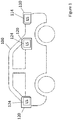
- FIG. 1 there is shown a vehicle 100 comprising a plurality of image capturing devices 110, 120.
- the plurality of image capturing devices are designated as a first image capturing device 110 and one or more additional image capturing devices 120 (only two of which are shown).
- a front facing image capturing device 110 is designated as the first image capturing device 110.
- the additional image capturing devices 120 include: a rear facing image capturing device; a left facing image capturing device (not shown); and a right facing image capturing device.
- Image capturing devices 110, 120 can comprise any type of image capturing device.
- an image capturing device may be a camera of the type commonly referred to as a digital camera.
- Such cameras may be, for example, CMOS cameras, charged coupled device (CCD) cameras and the like.
- CCD charged coupled device
- the image capturing devices 110, 120 can be the same or different types of devices and that the image capturing device may be able to capture an image in the visible and/or not visible spectrum including either ultra-violet or infra-red image information. Nonetheless, as will be appreciated from the description below, as a common feature extraction processor will interface with images provided from each of the devices 110, 120, the form of the image information provided by each image capturing device 110, 120 needs to be at least the same resolution and a compatible format.
- Images captured from the devices 110, 120 can also be processed to select a region of interest (ROI) from the image and/or to reduce its resolution.
- the image or ROI can comprise image information in any combination of intensity planes, such as YCC, YUV or LAB; or any combination of colour planes, for example, RGB.
- the image or ROI can contain values derived from a captured image such as a Histogram of Gradients (HOG) map or DCT coefficients or the image can comprise the result of a transform of a captured image, for example, a Hough transform.
- HOG Histogram of Gradients
- the image capturing devices 110, 120 have a 2 Mega Pixel (MP) resolution and the resolution of the captured image may be advantageously downsized to 1 MP to obtain input images, each having 3 1024x960 image planes.
- MP Mega Pixel
- the front facing image capturing device 110 may be mounted in any desired location on the vehicle 100 for capturing a downward looking plan view of the ground towards the front of the vehicle or for capturing an image looking in a generally forward direction from the vehicle 100. So for example, while the image capturing device 110, is illustrated mounted at or in the front grille of the vehicle 100, the image capturing device 110 could also be located within an overhead console unit (not shown) located within the cabin of the vehicle or the image capturing device 110 could be located on a forward facing surface of a rear view mirror (not shown).
- the rear facing image capturing device 120 may also be mounted in any desired location on the vehicle 100 for capturing a downward looking plan view of the ground towards the rear of the vehicle or for capturing an image looking in a generally backward direction from the vehicle 100.
- rear facing image capturing device 120 is shown mounted at a rear panel of the vehicle, the rear facing image capturing device could also be mounted inside a rear windscreen or indeed the rear facing image capturing device could comprise one or other of a pair of rear facing wing mirror mounted cameras.
- the right facing image capturing device 120 may be mounted in any desired location on the vehicle for capturing a downward looking plan view of the ground towards the right of the vehicle or for capturing an image looking in a generally leftward direction from the vehicle 100.
- the left facing image capturing device may be mounted in any desired location on the vehicle for capturing a downward looking plan view of the ground towards the left of the vehicle or for capturing an image looking in a generally leftward direction from the vehicle 100.
- the left/right image capturing devices could comprise one or other of a side facing wing mirror mounted camera, but such capturing devices could also be mounted at a side middle panel of the vehicle or inside a side windscreen.
- the image capturing devices 110, 120 have a field of view different from one another to the extent that in some cases, the fields of view may not even overlap.
- each image capturing device 110, 120 comprises a respective light sensor 114, 124 to sense the ambient light level intensity and output a value (L1, L2...L2n) indicating the intensity of light detected in the respective field of view of the image capturing device.
- the sensor may comprise a discrete sensor separate from an image sensor of the image capturing devices 110, 120 or ambient light level intensity can be determined directly from the image sensor.
- the vehicle 100 may also be fitted with one or more sensors including at least one of: a vehicle internal ambient temperature sensor; an external ambient temperature sensor; an external ambient pressure sensor; a vehicle internal humidity sensor; and an external humidity sensor. Each sensor provides a value indicative of the intensity of the detected parameter.
- FIG. 2 there is shown a block diagram of a neural network image processing apparatus 200 according to an embodiment of the present invention.
- the embodiment is implemented with convolutional neural network (CNN) type network designs.
- CNN convolutional neural network
- variants of the embodiment may be based on other forms of processing network including for example, R-CNNs (Region Based Convolution Neural Network).
- the apparatus 200 includes one or more processors (not shown) capable of processing instances of the various types of convolutional layers and fully connected (FC) layers comprising CNNs and the functional relationship between these layers is shown in Figure 2 .
- the physical apparatus which underlies the structure illustrated in Figure 2 may comprise: a single general processor which performs the processing required by each illustrated block; a dedicated processor specifically arranged for handling the processing of neural network layers; or a multi-processor core comprising a plurality of either dedicated or general-purpose processors which may perform certain processing in parallel.
- general purpose processor applies to large instruction set processors as well as RISC processors such as those provided by ARM.
- the apparatus 200 is coupled to the plurality of image capturing devices 110, 120 to obtain input images 112, 122 from the plurality of image capturing devices 110, 120.
- these input images may be processed or cropped ROIs and may comprise maps derived from or transformations of the original input image information - for simplicity, these are referred to below as input images.
- Input images 112, 122 are fed through respective instances of a CNN encoder 230 that performs feature extraction from the input images to produce a respective feature map from each of the input images (FM1, FM2...FM2n).
- instances of CNN encoder 230 can be executed sequentially or in parallel.
- the CNN encoder 230 comprises a number of processing layers 1 to N. Each layer comprises a convolution followed by optional subsampling. Each layer produces one or more feature maps. The size of the resulting map after each convolution layer may be reduced by subsampling (examples of which are average pooling or max-pooling) and/or by using a stride greater than 1 within a convolutional layer. For example, a first convolution layer performs 2D convolution of an original 2D image to produce its output map, while subsequent convolution layers perform convolutions using the output maps produced by the previous layer as inputs to produce an output feature map from the input image. In the embodiment, the final feature map has a lower spatial resolution than the corresponding input image 112 and it is this feature map which includes information that will be used to classify whether there is soiling of the original image 112 produced by the first image capturing device 110.
- CNN encoder 230 can comprise any type of architecture such as, but not limited to: a ResNet; a DenseNet; or a VNet.
- the CNN encoder 230 architecture may also include any number of layers. It is appreciated that depending on the type and/or size of the architecture the resulting height, width and channel/depth dimension of the output map of the CNN encoder 230 may vary.
- the CNN encoder 230 can comprise a ResNet50 (50 layers) architecture.
- the input image size is 1024x960x3
- the output map of the ResNet50 architecture would be 32x30x2048 (32 height pixels, 30 width pixels, 2048 channels or depth dimension). Accordingly, the height and width of the input image are reduced by a factor of 32 in response to the ResNet50 architecture. The resulting depth dimension depends on the ResNet50 architecture.
- the CNN encoder 230 can comprise a VNet8 (8 layers) architecture.
- the output map of a VNet8 architecture would be 40x30x512 (40 height pixels, 30 width pixels, 518 channels or depth dimension). Again, the resulting depth dimension depends on the VNet8 architecture.
- Each of the feature maps FM1, FN2...FM2n produced by respective instances of the encoder 230 is fed to instances of respective fully connected networks FCL1 and FCL2.
- the first fully connected network 240 (FCL1) and the second fully connected network 250 (FCL2) perform initial classification of the received feature maps from the instances of CNN encoder 230, with fully connected network FCL1 being connected to the output of the instance of CNN encoder 230 connected to the first image capturing device 110; and respective instances of fully connected network FCL2 being connected to the output of the instances of CNN encoder 230 connected to each of the additional image capturing devices 120.
- the feature maps values of FM1, FM2...FM2n are fed to nodes of an input layer of respective networks FCL1 and FCL2 where they are combined with weights and fed through an activation function to provide a set of output values to a successive layer and so on until the final output layer of each network FCL1, FCL2 provides a one-dimensional array of features (FV1) from the first FC layer 240 and one-dimensional array of features (FV2... FV2n) from each instance of the second FC network 250.
- the combined encoders 230 and fully connected networks 240, 250 are trained using suitably annotated training images so that for any probe image, each feature vector FV1 and FV2...FV2n indicates a soiling of a corresponding input image.
- each feature vector FV1 and FV2...FV2n indicates a soiling of a corresponding input image.
- the annotated training images can also be provided with annotations for tasks unrelated to soiling, for example, for object detection, semantic segmentation or soiling segmentation as will be explained below.
- each element of the feature vectors FV1 and FV2...FV2n comprises a probabilistic measure between 0...1, but it will be appreciated that other ranges such as [-1 to 1] could also be used.
- the apparatus 200 is testing whether an image produced by first image capturing device 110 is soiled.
- the output vector FV1 of the first FC layer 240 would be 6144 bytes.
- each instance of the fully connected layer FCL2 250 processes a respective feature map FM2...FM2n to produce an output feature vector FV2...FV2n comprising 14 values, each element of the vector, C1...C14, comprising a confidence score corresponding to a class of soiling, which may be affecting the image provided by a respective image capturing device from the additional image capturing devices 120.
- the classes include mud; sand; grass; dust; water; rain drops; oil; wax; vaseline; polish; salt-spray; transparent; opaque; and other, although it will be appreciated that in variants of the embodiment fewer or more classes may be used - or indeed only a single generic soiling classification may be provided by each instance of FCL2 250.
- the 3x14 classifications provided by each instance of FCL2, 250, along with the light levels provided by the sensors 114,124, the feature vector FV1 provided by the FCL1, 240 and the temperature value provided by the temperature sensor are concatenated to provide an input to a further fully connected layer FCL3, 270.
- sensor values from sensors such as those listed above can be used in addition or as an alternative to the light and temperature values provided by those sensors.
- classification networks 240, 250 do not need to be limited to comprising fully connected layers only and for example, may also comprise further convolutional layers, if required.
- the fully connected layer FCL3 270 is arranged to provide soiling classifications C1'... C'14 for the corresponding first image 112 based on these inputs as well as a generic soiling classification C15.
- each output of FCL3 270 can comprise a probabilistic measure between 0...1, but equally any range of values indicating either generic soiling C15 or a specific class of soiling can be employed.
- Providing individual soiling classifications C1'...C'14 as well as the generic classification C15 means that if an image produced by the designated first image capturing device 110 is determined to be soiled, for example, by frost, then a vehicle controller (not shown) which receives the classifications C'1...C'14 for the image capturing device 110 can cause a cleaning system to clean the device 110 by heating; whereas if an image produced by the designated first image capturing device 110 is determined to be soiled by dirt, then the cleaning system might better spray water on the device 110.
- the classifications C1...C14 derived from the additional image capturing devices 120 can boost the soiling classification which might otherwise have been derived only from the first image 112 itself.
- FCL3 270 may be able to provide higher confidence scores or better discriminate probe images from the image capturing device 110 that are soiled by ice or frost.
- any of the additional image capturing devices 120 can then be designated as the first image capturing device 110.
- classification networks FCL1...FCL3 need only execute for any given first image capturing device 110 at a much lower frequency, possibly less than one per second, than for example object detection classifiers, which might be required to run at a frame rate of greater than 30 frames per second.
- Soiling segmentation may comprise applying a decoder (not shown) to create a mask, potentially as large as the input image 112, from the feature map FM1 received from the CNN encoder 230, with each element of the mask indicating soiling of one or more pixels of the input image 112 in the vicinity of the element.
- the segmentation decoder can comprise any type of architecture such as, a standard FCN8, 16 or Deconv Net.
- the architecture of the segmentation decoder includes enough layers to upscale the spatial dimensions of the feature map FM1 to those of the input image.
- one such useful task which might be performed using the feature map FM1 produced from the first image 112 is object detection, with a view to identifying one or more regions of an image bounding an object of a given class, for example, as described at https://towardsdatascience.com/r-cnn-fast-r-cnn-faster-r-cnn-yolo-object-detection-algorithms-36d53571365e.
- object detection can be performed in conjunction with a soiling mask to improve the discrimination of such object detection.
- Other tasks comprise semantic segmentation which involves dividing an image into sub-regions and labelling these in accordance with their content, thus each pixel is labelled with the class of its enclosing object or region.
- semantic segmentation More information on semantic segmentation can be found at https://sthalles.github.io/deep_segmentation_network /; or https://www.jeremyjordan.me/semantic-segmentation/ . Indeed, similar techniques for performing general semantic segmentation can be employed for soiling segmentation, to divide an image into pixels classified as either being affected by soiling or not.
- Such training can comprise iteratively training the system by first training the encoders 230 and the further processing stages such as object detectors based on unsoiled images. Note that sets of unsoiled images provided to the apparatus 200 during training should ideally be simultaneously acquired from the various image capturing devices 110, 120 along with simultaneous sensor values and light sensor values.
- the classifier network comprising FCL1...FCL3 can be trained based on both soiled and non-soiled training images.
- a soiling segmentation network can be trained for detecting soiled pixels and finally the complete network, with a trained soiling segmentation classifier network feeding into one or both of an object detection and/or a semantic segmentation classifier network, can be trained based on soiled and non-soiled images.
Landscapes
- Engineering & Computer Science (AREA)
- Physics & Mathematics (AREA)
- General Physics & Mathematics (AREA)
- Multimedia (AREA)
- Theoretical Computer Science (AREA)
- Image Analysis (AREA)
Abstract
Description
- The present application relates to a neural network image processing apparatus and a method for processing an image with a neural network apparatus.
- Vehicle systems, such as automatic emergency braking, autonomous parking or driving systems, use image capture devices to detect objects such as cars and/or pedestrians in the environment of a vehicle with a view to controlling, braking or steering the vehicle, as required.
- There is a need to detect the presence of an impediment to light passing through the lens of such image capture devices, and in particular, to detect the presence of an impediment, for example dirt, on the lens of vehicle mounted image capture devices.
-
EP2351351 (Ref: SIE0007) discloses a method for detecting the presence of dirt on the lens of a camera comprising passing image data of sequentially captured images through a high pass filter for detecting predefined areas in the captured image frames, the image data of which is indicative of an area of low or no high spatial frequency content, which could possibly be as a result of dirt on the lens. The locations of the predefined areas in which the image data thereof is indicative of an area of low or no high spatial frequency content in the currently captured image frame is stored in memory, for comparison with the next captured image frame. -
EP2795582 (Ref: SIE0048) discloses a method in which respective fields of view of a first camera and a second camera overlap at least in a partial region. At least in an image captured by the first camera, at least one contamination region including a plurality of pixels is detected within the partial region. Thereupon, data values specifying the respective transparency of the pixels in the at least one contamination region are varied with respect to respective reference values of the transparency, wherein these reference values increase in the partial region towards an edge of the respective image upon superimposition of the images. -
WO2017/021417 (Ref: SIE0202) discloses a camera system in which a micro-lens array is disposed in front of at least one image sensor of a plenoptic camera of the camera system and an image of an environmental region of the motor vehicle is captured by the plenoptic camera, wherein a deposition of particles on an optical system of the plenoptic camera is identified based on at least one characteristic of an image area at least of the image. - It is an object of the present invention to improve such systems.
- Accordingly, in a first aspect the application provides a neural network image processing apparatus as detailed in claim 1.
- In a further aspect there is provided a method for processing an image at a neural network apparatus as detailed in claim 17.
- In still a further aspect, there is provided a computer program product which when executed on a computing device is arranged to perform the method of claim 17.
- In another aspect, there is provided a vehicle comprising a neural network image processing apparatus of claim 1.
- Advantageous embodiments are provided in the dependent claims.
- Embodiments of the present invention can detect if any given image capturing device within a plurality of image capturing devices is soiled and, depending on a soiling score, only then perform tasks such as object detection, semantic segmentation or soiling segmentation on images produced by the image capturing device.
- Embodiments use soiling conditions from at least one image capturing device other than the given image capturing device and that has a different field of view than the given image capturing device to boost decision-making in relation to soiling of the given image capturing device. This can be performed for each image capturing device of the system in turn.
- Embodiments can be trained end-to-end so that all components of the apparatus are fully synergized to work together optimally.
- Some embodiments provide soiling types of various classes (e.g. opaque, frost, water, broken lens, etc) as well as or as an alternative to a generic soiling classification.
-
-
Figure 1 illustrates a vehicle comprising image capturing devices which are connected to a neural network image processing apparatus according to an embodiment of the invention; and -
Figure 2 is a block diagram illustrating a configuration of a neural network image processing apparatus according to an embodiment of the invention. - In
Figure 1 there is shown avehicle 100 comprising a plurality ofimage capturing devices device 110 and one or more additional image capturing devices 120 (only two of which are shown). In the example, a front facingimage capturing device 110 is designated as the first image capturingdevice 110. The additionalimage capturing devices 120 include: a rear facing image capturing device; a left facing image capturing device (not shown); and a right facing image capturing device. - Image capturing
devices image capturing devices devices image capturing device - Images captured from the
devices - In the embodiment, the
image capturing devices - The front facing
image capturing device 110 may be mounted in any desired location on thevehicle 100 for capturing a downward looking plan view of the ground towards the front of the vehicle or for capturing an image looking in a generally forward direction from thevehicle 100. So for example, while the image capturingdevice 110, is illustrated mounted at or in the front grille of thevehicle 100, the image capturingdevice 110 could also be located within an overhead console unit (not shown) located within the cabin of the vehicle or the image capturingdevice 110 could be located on a forward facing surface of a rear view mirror (not shown). - The rear facing
image capturing device 120 may also be mounted in any desired location on thevehicle 100 for capturing a downward looking plan view of the ground towards the rear of the vehicle or for capturing an image looking in a generally backward direction from thevehicle 100. - Again, while the rear facing
image capturing device 120 is shown mounted at a rear panel of the vehicle, the rear facing image capturing device could also be mounted inside a rear windscreen or indeed the rear facing image capturing device could comprise one or other of a pair of rear facing wing mirror mounted cameras. - The right facing
image capturing device 120 may be mounted in any desired location on the vehicle for capturing a downward looking plan view of the ground towards the right of the vehicle or for capturing an image looking in a generally leftward direction from thevehicle 100. - Similarly, the left facing image capturing device (not shown) may be mounted in any desired location on the vehicle for capturing a downward looking plan view of the ground towards the left of the vehicle or for capturing an image looking in a generally leftward direction from the
vehicle 100. - Typically, the left/right image capturing devices could comprise one or other of a side facing wing mirror mounted camera, but such capturing devices could also be mounted at a side middle panel of the vehicle or inside a side windscreen.
- In any case, it will be seen that the
image capturing devices - In the embodiment, each
image capturing device respective light sensor image capturing devices - The
vehicle 100 may also be fitted with one or more sensors including at least one of: a vehicle internal ambient temperature sensor; an external ambient temperature sensor; an external ambient pressure sensor; a vehicle internal humidity sensor; and an external humidity sensor. Each sensor provides a value indicative of the intensity of the detected parameter. - Referring now to
Figure 2 there is shown a block diagram of a neural networkimage processing apparatus 200 according to an embodiment of the present invention. - The embodiment is implemented with convolutional neural network (CNN) type network designs. Although it will be appreciated that variants of the embodiment may be based on other forms of processing network including for example, R-CNNs (Region Based Convolution Neural Network).
- The
apparatus 200 includes one or more processors (not shown) capable of processing instances of the various types of convolutional layers and fully connected (FC) layers comprising CNNs and the functional relationship between these layers is shown inFigure 2 . As such, the physical apparatus which underlies the structure illustrated inFigure 2 may comprise: a single general processor which performs the processing required by each illustrated block; a dedicated processor specifically arranged for handling the processing of neural network layers; or a multi-processor core comprising a plurality of either dedicated or general-purpose processors which may perform certain processing in parallel. It will be appreciated that the term general purpose processor applies to large instruction set processors as well as RISC processors such as those provided by ARM. - The
apparatus 200 is coupled to the plurality ofimage capturing devices input images image capturing devices -
Input images encoder 230 that performs feature extraction from the input images to produce a respective feature map from each of the input images (FM1, FM2...FM2n). As indicated above, depending on the processing platform which is available within theapparatus 200, instances of CNNencoder 230 can be executed sequentially or in parallel. - The CNN
encoder 230 comprises a number of processing layers 1 to N. Each layer comprises a convolution followed by optional subsampling. Each layer produces one or more feature maps. The size of the resulting map after each convolution layer may be reduced by subsampling (examples of which are average pooling or max-pooling) and/or by using a stride greater than 1 within a convolutional layer. For example, a first convolution layer performs 2D convolution of an original 2D image to produce its output map, while subsequent convolution layers perform convolutions using the output maps produced by the previous layer as inputs to produce an output feature map from the input image. In the embodiment, the final feature map has a lower spatial resolution than thecorresponding input image 112 and it is this feature map which includes information that will be used to classify whether there is soiling of theoriginal image 112 produced by the firstimage capturing device 110. -
CNN encoder 230 can comprise any type of architecture such as, but not limited to: a ResNet; a DenseNet; or a VNet. TheCNN encoder 230 architecture may also include any number of layers. It is appreciated that depending on the type and/or size of the architecture the resulting height, width and channel/depth dimension of the output map of theCNN encoder 230 may vary. - In a first example, the
CNN encoder 230 can comprise a ResNet50 (50 layers) architecture. In this case, if the input image size is 1024x960x3, the output map of the ResNet50 architecture would be 32x30x2048 (32 height pixels, 30 width pixels, 2048 channels or depth dimension). Accordingly, the height and width of the input image are reduced by a factor of 32 in response to the ResNet50 architecture. The resulting depth dimension depends on the ResNet50 architecture. - In an alternative example, the
CNN encoder 230 can comprise a VNet8 (8 layers) architecture. In this case, if the input image size were 1280x960x3, the output map of a VNet8 architecture would be 40x30x512 (40 height pixels, 30 width pixels, 518 channels or depth dimension). Again, the resulting depth dimension depends on the VNet8 architecture. Each of the feature maps FM1, FN2...FM2n produced by respective instances of theencoder 230 is fed to instances of respective fully connected networks FCL1 and FCL2. The first fully connected network 240 (FCL1) and the second fully connected network 250 (FCL2) perform initial classification of the received feature maps from the instances ofCNN encoder 230, with fully connected network FCL1 being connected to the output of the instance ofCNN encoder 230 connected to the firstimage capturing device 110; and respective instances of fully connected network FCL2 being connected to the output of the instances ofCNN encoder 230 connected to each of the additionalimage capturing devices 120. The feature maps values of FM1, FM2...FM2n are fed to nodes of an input layer of respective networks FCL1 and FCL2 where they are combined with weights and fed through an activation function to provide a set of output values to a successive layer and so on until the final output layer of each network FCL1, FCL2 provides a one-dimensional array of features (FV1) from thefirst FC layer 240 and one-dimensional array of features (FV2... FV2n) from each instance of thesecond FC network 250. - As will be explained later, the combined
encoders 230 and fully connectednetworks - In some embodiments, each element of the feature vectors FV1 and FV2...FV2n comprises a probabilistic measure between 0...1, but it will be appreciated that other ranges such as [-1 to 1] could also be used.
- As indicated, in the illustrated example, the
apparatus 200 is testing whether an image produced by firstimage capturing device 110 is soiled. - Thus, in one example, where the output map of the
CNN encoder 230 is 40x30x512 (614000) bytes in size for each one of aninput image 112 provided by the firstimage capturing device 110, the output vector FV1 of thefirst FC layer 240 would be 6144 bytes. - Separately, in the present embodiment, each instance of the fully connected
layer FCL2 250 processes a respective feature map FM2...FM2n to produce an output feature vector FV2...FV2n comprising 14 values, each element of the vector, C1...C14, comprising a confidence score corresponding to a class of soiling, which may be affecting the image provided by a respective image capturing device from the additionalimage capturing devices 120. - In one example, the classes include mud; sand; grass; dust; water; rain drops; oil; wax; vaseline; polish; salt-spray; transparent; opaque; and other, although it will be appreciated that in variants of the embodiment fewer or more classes may be used - or indeed only a single generic soiling classification may be provided by each instance of
FCL2 250. - In the embodiment, the 3x14 classifications provided by each instance of FCL2, 250, along with the light levels provided by the sensors 114,124, the feature vector FV1 provided by the FCL1, 240 and the temperature value provided by the temperature sensor are concatenated to provide an input to a further fully connected layer FCL3, 270. In variants of the embodiment sensor values from sensors such as those listed above can be used in addition or as an alternative to the light and temperature values provided by those sensors.
- Also, it will be appreciated that the
classification networks - In any case, the fully connected
layer FCL3 270 is arranged to provide soiling classifications C1'... C'14 for the correspondingfirst image 112 based on these inputs as well as a generic soiling classification C15. Again, each output ofFCL3 270, can comprise a probabilistic measure between 0...1, but equally any range of values indicating either generic soiling C15 or a specific class of soiling can be employed. - Providing individual soiling classifications C1'...C'14 as well as the generic classification C15 means that if an image produced by the designated first
image capturing device 110 is determined to be soiled, for example, by frost, then a vehicle controller (not shown) which receives the classifications C'1...C'14 for theimage capturing device 110 can cause a cleaning system to clean thedevice 110 by heating; whereas if an image produced by the designated firstimage capturing device 110 is determined to be soiled by dirt, then the cleaning system might better spray water on thedevice 110. - In any case, the classifications C1...C14 derived from the additional
image capturing devices 120 can boost the soiling classification which might otherwise have been derived only from thefirst image 112 itself. - As well as using classifications derived from the additional
image capturing devices 120, it will be seen how incorporating sensor values can boost the accuracy of confidence levels produced for various types of soiling of the firstimage capturing device 110. For example, if the ambient temperature value is close to 0 degree centigrade,FCL3 270 may be able to provide higher confidence scores or better discriminate probe images from theimage capturing device 110 that are soiled by ice or frost. - It will be seen that once a set of classifications C'1...C'14, C15 has been produced for a designated first
image capturing device 110, any of the additionalimage capturing devices 120 can then be designated as the firstimage capturing device 110. - In this case, it will not be necessary to re-execute instances of the
encoders 230 which were used in generating the soiling classifications for the original designated firstimage capturing device 110, but it will be necessary to execute an instance of FCL1 for the feature map produced byencoder 230 from the additionalimage capturing device 120 chosen as the designated firstimage capturing device 110; and equally to execute an instance of FCL2 for the feature map produced by theencoder 230 from the previous designated firstimage capturing device 110 now being employed as an additionalimage capturing device 120. - Nonetheless, it will be appreciated that as changes in soiling occur relatively unfrequently by comparison to the rate at which tasks such as object detection may need to be performed, for example, by an autonomous vehicle, classification networks FCL1...FCL3 need only execute for any given first
image capturing device 110 at a much lower frequency, possibly less than one per second, than for example object detection classifiers, which might be required to run at a frame rate of greater than 30 frames per second. - It will also be appreciated that if soiling of a given image capturing device, for example, the front image capturing device, within a number of image capturing devices is more critical than for others, processing by the
apparatus 200 of images produced by this device as a firstimage capturing device 110 can be more frequent than for others of the image capturing devices. - In any case, when the soiling classification for a given first
image capturing device 110 indicates that the level of soiling of an image is below a threshold level, then further processing of theimage 112 and images subsequently acquired by the given firstimage capturing device 110 until classification is re-executed can be performed. - One type of such further processing comprises providing a soiling map for the first
image capturing device 110, a process referred to as soiling segmentation. Soiling segmentation may comprise applying a decoder (not shown) to create a mask, potentially as large as theinput image 112, from the feature map FM1 received from theCNN encoder 230, with each element of the mask indicating soiling of one or more pixels of theinput image 112 in the vicinity of the element. The segmentation decoder can comprise any type of architecture such as, a standard FCN8, 16 or Deconv Net. The architecture of the segmentation decoder includes enough layers to upscale the spatial dimensions of the feature map FM1 to those of the input image. - Nonetheless, it will be appreciated that generating such a soiling mask is computationally expensive and as such, it is desirable only to do so in circumstances where soiling is not so extensive as to preclude the possibility of other useful tasks which might be performed on the
first image 112. - Indeed regenerating a soiling mask for any given image capturing device may only need to be done in response to fluctuations in the value of soiling classifications C'1 ... C'14, C15 provided by the
apparatus 200. - As indicated, one such useful task which might be performed using the feature map FM1 produced from the
first image 112 is object detection, with a view to identifying one or more regions of an image bounding an object of a given class, for example, as described at https://towardsdatascience.com/r-cnn-fast-r-cnn-faster-r-cnn-yolo-object-detection-algorithms-36d53571365e. Such object detection can be performed in conjunction with a soiling mask to improve the discrimination of such object detection. Other tasks comprise semantic segmentation which involves dividing an image into sub-regions and labelling these in accordance with their content, thus each pixel is labelled with the class of its enclosing object or region. More information on semantic segmentation can be found at https://sthalles.github.io/deep_segmentation_network/; or https://www.jeremyjordan.me/semantic-segmentation/. Indeed, similar techniques for performing general semantic segmentation can be employed for soiling segmentation, to divide an image into pixels classified as either being affected by soiling or not. - It will be appreciated that consideration needs to be given to training systems including the
apparatus 200 as well as further processing stages, where a givenencoder 230 is used to produce a feature map FM1, FM2..FM2n which will in turn be used to produce soiling classifications through networks FCL1...FCL3, but which can be separately provided as a basis for performing soiling segmentation, semantic segmentation and/or object detection. - Such training can comprise iteratively training the system by first training the
encoders 230 and the further processing stages such as object detectors based on unsoiled images. Note that sets of unsoiled images provided to theapparatus 200 during training should ideally be simultaneously acquired from the variousimage capturing devices - Now the classifier network comprising FCL1...FCL3 can be trained based on both soiled and non-soiled training images.
- Then a soiling segmentation network can be trained for detecting soiled pixels and finally the complete network, with a trained soiling segmentation classifier network feeding into one or both of an object detection and/or a semantic segmentation classifier network, can be trained based on soiled and non-soiled images.
Claims (18)
- A neural network image processing apparatus (200) arranged to:obtain a first image (112) from a first image capturing device (110) and a respective additional image (124) from at least one additional image capturing device (120), wherein the first image capturing device has a field of view different than the or each additional image capturing device;process each of said first and the or each additional image through respective instances of a common feature extraction processing network (230) to produce a respective first map (FM1) and at least one additional map (FM2...FM2n), each having a lower spatial resolution than said first and the or each additional image;perform feature classification comprising:processing (240) said first map to provide a first classification (FV1) indicating a soiling of said first image;processing (250) the or each additional map to provide at least one additional classification (FV2...FV2n) indicating a respective soiling of said the or each additional image; andcombining (270) said first and the or each additional classification to provide a boosted classification (C15) indicating soiling of said first image; andresponsive to said boosted classification not indicating soiling of said first image capturing device, perform further processing of said first image based on said first map.
- The neural network image processing apparatus of claim 1, further arranged to:provide said first and the at least one additional classification at a frequency less than a frequency at which images are obtained by said first image capturing device.
- The neural network image processing apparatus of claim 1, wherein said first and the or each additional classification comprises respective feature vectors, said first classification feature vector comprising more elements than the or each additional classification feature vector.
- The neural network image processing apparatus of claim 3 wherein each element of the or each additional classification feature vector comprises a confidence level for a respective type of soiling of said additional image capturing device.
- The neural network image processing apparatus of claim 4 wherein the types of soiling include one or more of: mud; sand; grass; dust; water; rain drops; oil; wax; vaseline; polish; salt-spray; transparent; opaque; and other.
- The neural network image processing apparatus of claim 1, wherein said apparatus is further configured to perform object detection based on said first map to locate a specific object within said first image.
- The neural network image processing apparatus of claim 6, wherein said apparatus is further configured to perform soiling segmentation based on said first map to generate a mask for said first image capturing device, said mask comprising an array of elements, with each element indicating soiling of any image produced by said first image capturing device in the vicinity of said element.
- The neural network image processing apparatus of claim 7, wherein said apparatus is arranged to combine said mask with a feature map derived from said first map to perform said object detection.
- The neural network image processing apparatus of claim 1, wherein the apparatus is arranged to perform feature classification by:concatenating said first and the at least one additional classifications; andfeeding said concatenated classification to a fully connected neural network to provide at least said boosted soiling classification.
- The neural network image processing apparatus of claim 1, wherein the apparatus is arranged to obtain respective light level values (L1...L2n) associated with each of said first and the at least one additional images and to combine said light level values with said first and the at least one additional classifications to provide the boosted classification indicating soiling of said first image.
- The neural network image processing apparatus of claim 1, wherein the apparatus is arranged to obtain one or more sensor output values (T) and to combine said sensor output values with said first and the at least one additional classifications to provide the boosted classification indicating soiling of said first image.
- The neural network image processing apparatus of claim 11, wherein the one or more sensors comprises at least one of:a vehicle internal ambient temperature sensor;an external ambient temperature sensor;an external ambient pressure sensor;a vehicle internal humidity sensor; andan external humidity sensor.
- The neural network image processing apparatus of claim 1 wherein the first and the or each additional image capturing devices are each different devices in the group of:a front facing image capturing devicea rear facing image capturing device;a left facing image capturing device; ora right facing image capturing device.
- The neural network image processing apparatus of claim 1 configured to repeat the processing of a set of images acquired from a plurality of image capturing devices with a different one of the images capturing devices being designated as said first image capturing device.
- The neural network image processing apparatus of claim 1 wherein the first and the or each additional image capturing devices are optical image capturing devices configured to obtain visible light images.
- A vehicle comprising:a neural network image processing apparatus of claim 1; anda controller being responsive to said boosted classification indicating of a soiling affecting the first image to instruct a vehicle cleaning system to perform a cleaning of the lens of the first image capturing device.
- A method for processing an image at a neural network apparatus, the method comprising:obtaining a first image from a first image capturing device and a respective additional image from at least one additional image capturing device, wherein the first image capturing device has a field of view different than the or each additional image capturing device;processing each of said first and the or each additional image through respective instances of a common feature extraction processing network to produce a respective first map and at least one additional map, each having a lower spatial resolution than said first and the or each additional image;performing feature classification by:processing said first map to provide a first classification indicating a soiling of said first image;processing the or each additional map to provide at least one additional classification indicating a respective soiling of said the or each additional image; andcombining said first and the or each additional classification to provide a boosted classification indicating soiling of said first image; andresponsive to said boosted classification not indicating soiling of said first image capturing device, performing further processing of said first image based on said first map.
- A computer program product which when executed on a computing device is arranged to perform the method of claim 17.
Priority Applications (1)
| Application Number | Priority Date | Filing Date | Title |
|---|---|---|---|
| EP18208206.5A EP3657379B1 (en) | 2018-11-26 | 2018-11-26 | A neural network image processing apparatus for detecting soiling of an image capturing device |
Applications Claiming Priority (1)
| Application Number | Priority Date | Filing Date | Title |
|---|---|---|---|
| EP18208206.5A EP3657379B1 (en) | 2018-11-26 | 2018-11-26 | A neural network image processing apparatus for detecting soiling of an image capturing device |
Publications (2)
| Publication Number | Publication Date |
|---|---|
| EP3657379A1 true EP3657379A1 (en) | 2020-05-27 |
| EP3657379B1 EP3657379B1 (en) | 2026-02-18 |
Family
ID=64476963
Family Applications (1)
| Application Number | Title | Priority Date | Filing Date |
|---|---|---|---|
| EP18208206.5A Active EP3657379B1 (en) | 2018-11-26 | 2018-11-26 | A neural network image processing apparatus for detecting soiling of an image capturing device |
Country Status (1)
| Country | Link |
|---|---|
| EP (1) | EP3657379B1 (en) |
Cited By (9)
| Publication number | Priority date | Publication date | Assignee | Title |
|---|---|---|---|---|
| CN111881906A (en) * | 2020-06-18 | 2020-11-03 | 广州万维创新科技有限公司 | LOGO identification method based on attention mechanism image retrieval |
| DE102021103200B3 (en) | 2021-02-11 | 2022-06-23 | Connaught Electronics Ltd. | Method for determining a degree of degradation of a recorded image, computer program product, computer-readable storage medium and assistance system |
| DE102021201255A1 (en) | 2021-02-10 | 2022-08-11 | Robert Bosch Gesellschaft mit beschränkter Haftung | Computer-implemented method and system for detecting a visual impairment of an imaging sensor and training method |
| DE102021208423A1 (en) | 2021-08-04 | 2023-02-09 | Zf Friedrichshafen Ag | Method and computer program for protecting a perception system against contamination of an imaging sensor of the perception system and perception system of an automated driving system |
| GB2611408A (en) * | 2021-08-04 | 2023-04-05 | Motional Ad Llc | Scalable and realistic camera blockage dataset generation |
| DE102023118374A1 (en) * | 2023-07-12 | 2025-01-16 | Connaught Electronics Ltd. | Method for detecting cleaning of a lens of a camera for a motor vehicle by means of an electronic computing device of the motor vehicle, computer program product, computer-readable storage medium and electronic computing device |
| US12333828B2 (en) | 2021-08-04 | 2025-06-17 | Motional Ad Llc | Scalable and realistic camera blockage dataset generation |
| DE102024101706A1 (en) * | 2024-01-22 | 2025-07-24 | Connaught Electronics Ltd. | Method for determining impairment information describing an impairment of at least one camera for a vehicle due to contamination and/or glare |
| US12548311B2 (en) | 2021-08-04 | 2026-02-10 | Motional Ad Llc | Training a neural network using a data set with labels of multiple granularities |
Citations (6)
| Publication number | Priority date | Publication date | Assignee | Title |
|---|---|---|---|---|
| US20050254688A1 (en) * | 2002-01-17 | 2005-11-17 | Matthias Franz | Method and device for recognizing obstruction of view in image sensor systems |
| US20090174773A1 (en) * | 2007-09-13 | 2009-07-09 | Gowdy Jay W | Camera diagnostics |
| EP2351351A1 (en) | 2008-10-01 | 2011-08-03 | HI-KEY Limited | A method and a system for detecting the presence of an impediment on a lens of an image capture device to light passing through the lens of an image capture device |
| EP2795582A1 (en) | 2011-12-24 | 2014-10-29 | Connaught Electronics Ltd. | Method for operating a camera assembly, camera assembly and driver assistance system |
| WO2017021417A1 (en) | 2015-08-03 | 2017-02-09 | Connaught Electronics Ltd. | Method for operating a camera system with a plenoptic camera, camera system and motor vehicle |
| US20170270368A1 (en) * | 2016-03-15 | 2017-09-21 | Robert Bosch Gmbh | Method for detecting a soiling of an optical component of a driving environment sensor used to capture a field surrounding a vehicle; method for automatically training a classifier; and a detection system |
-
2018
- 2018-11-26 EP EP18208206.5A patent/EP3657379B1/en active Active
Patent Citations (7)
| Publication number | Priority date | Publication date | Assignee | Title |
|---|---|---|---|---|
| US20050254688A1 (en) * | 2002-01-17 | 2005-11-17 | Matthias Franz | Method and device for recognizing obstruction of view in image sensor systems |
| US20090174773A1 (en) * | 2007-09-13 | 2009-07-09 | Gowdy Jay W | Camera diagnostics |
| EP2351351A1 (en) | 2008-10-01 | 2011-08-03 | HI-KEY Limited | A method and a system for detecting the presence of an impediment on a lens of an image capture device to light passing through the lens of an image capture device |
| EP2795582A1 (en) | 2011-12-24 | 2014-10-29 | Connaught Electronics Ltd. | Method for operating a camera assembly, camera assembly and driver assistance system |
| US20170163886A1 (en) * | 2011-12-24 | 2017-06-08 | Connaught Electronics Ltd. | Method for operating a camera assembly, camera assembly and driver assistance system |
| WO2017021417A1 (en) | 2015-08-03 | 2017-02-09 | Connaught Electronics Ltd. | Method for operating a camera system with a plenoptic camera, camera system and motor vehicle |
| US20170270368A1 (en) * | 2016-03-15 | 2017-09-21 | Robert Bosch Gmbh | Method for detecting a soiling of an optical component of a driving environment sensor used to capture a field surrounding a vehicle; method for automatically training a classifier; and a detection system |
Cited By (12)
| Publication number | Priority date | Publication date | Assignee | Title |
|---|---|---|---|---|
| CN111881906A (en) * | 2020-06-18 | 2020-11-03 | 广州万维创新科技有限公司 | LOGO identification method based on attention mechanism image retrieval |
| DE102021201255A1 (en) | 2021-02-10 | 2022-08-11 | Robert Bosch Gesellschaft mit beschränkter Haftung | Computer-implemented method and system for detecting a visual impairment of an imaging sensor and training method |
| CN114943265A (en) * | 2021-02-10 | 2022-08-26 | 罗伯特·博世有限公司 | Method and system for detecting visual line obstruction of imaging sensor and training method |
| DE102021103200B3 (en) | 2021-02-11 | 2022-06-23 | Connaught Electronics Ltd. | Method for determining a degree of degradation of a recorded image, computer program product, computer-readable storage medium and assistance system |
| WO2022171590A1 (en) | 2021-02-11 | 2022-08-18 | Connaught Electronics Ltd. | Method for determining a degradation degree of a captured image, computer program product, computer-readable storage medium as well as assistance system |
| DE102021208423A1 (en) | 2021-08-04 | 2023-02-09 | Zf Friedrichshafen Ag | Method and computer program for protecting a perception system against contamination of an imaging sensor of the perception system and perception system of an automated driving system |
| GB2611408A (en) * | 2021-08-04 | 2023-04-05 | Motional Ad Llc | Scalable and realistic camera blockage dataset generation |
| GB2611408B (en) * | 2021-08-04 | 2024-04-03 | Motional Ad Llc | Scalable and realistic camera blockage dataset generation |
| US12333828B2 (en) | 2021-08-04 | 2025-06-17 | Motional Ad Llc | Scalable and realistic camera blockage dataset generation |
| US12548311B2 (en) | 2021-08-04 | 2026-02-10 | Motional Ad Llc | Training a neural network using a data set with labels of multiple granularities |
| DE102023118374A1 (en) * | 2023-07-12 | 2025-01-16 | Connaught Electronics Ltd. | Method for detecting cleaning of a lens of a camera for a motor vehicle by means of an electronic computing device of the motor vehicle, computer program product, computer-readable storage medium and electronic computing device |
| DE102024101706A1 (en) * | 2024-01-22 | 2025-07-24 | Connaught Electronics Ltd. | Method for determining impairment information describing an impairment of at least one camera for a vehicle due to contamination and/or glare |
Also Published As
| Publication number | Publication date |
|---|---|
| EP3657379B1 (en) | 2026-02-18 |
Similar Documents
| Publication | Publication Date | Title |
|---|---|---|
| EP3657379B1 (en) | A neural network image processing apparatus for detecting soiling of an image capturing device | |
| US11270134B2 (en) | Method for estimating distance to an object via a vehicular vision system | |
| CN101633356B (en) | System and method for detecting pedestrians | |
| US10423843B2 (en) | Vehicle vision system with enhanced traffic sign recognition | |
| US9286512B2 (en) | Method for detecting pedestrians based on far infrared ray camera at night | |
| US10650255B2 (en) | Vehicular vision system with object detection | |
| JP6266238B2 (en) | Approaching object detection system and vehicle | |
| US9363483B2 (en) | Method for available parking distance estimation via vehicle side detection | |
| US7684590B2 (en) | Method of recognizing and/or tracking objects | |
| JP7135665B2 (en) | VEHICLE CONTROL SYSTEM, VEHICLE CONTROL METHOD AND COMPUTER PROGRAM | |
| Li et al. | Full-time monocular road detection using zero-distribution prior of angle of polarization | |
| US20180151063A1 (en) | Real-time detection system for parked vehicles | |
| CN109145798B (en) | An integrated method for target recognition and drivable area segmentation in driving scenes | |
| US20090174773A1 (en) | Camera diagnostics | |
| US20130162826A1 (en) | Method of detecting an obstacle and driver assist system | |
| US10984264B2 (en) | Detection and validation of objects from sequential images of a camera | |
| Sandhawalia et al. | Vehicle type classification from laser scanner profiles: A benchmark of feature descriptors | |
| CN115240170B (en) | A road pedestrian detection and tracking method and system based on event camera | |
| WO2019085929A1 (en) | Image processing method, device for same, and method for safe driving | |
| CN110226326A (en) | For detecting the picture pick-up device and method of the surrounding area of vehicle | |
| Webster et al. | Improved raindrop detection using combined shape and saliency descriptors with scene context isolation | |
| CN115082867A (en) | Method and system for object detection | |
| Routray et al. | A fast edge detection algorithm for road boundary extraction under non-uniform light condition | |
| US20230267749A1 (en) | System and method of segmenting free space based on electromagnetic waves | |
| EP3329419A1 (en) | Method for capturing an object on a road in the environment of a motor vehicle, camera system and motor vehicle using the same |
Legal Events
| Date | Code | Title | Description |
|---|---|---|---|
| PUAI | Public reference made under article 153(3) epc to a published international application that has entered the european phase |
Free format text: ORIGINAL CODE: 0009012 |
|
| STAA | Information on the status of an ep patent application or granted ep patent |
Free format text: STATUS: THE APPLICATION HAS BEEN PUBLISHED |
|
| AK | Designated contracting states |
Kind code of ref document: A1 Designated state(s): AL AT BE BG CH CY CZ DE DK EE ES FI FR GB GR HR HU IE IS IT LI LT LU LV MC MK MT NL NO PL PT RO RS SE SI SK SM TR |
|
| AX | Request for extension of the european patent |
Extension state: BA ME |
|
| RIN1 | Information on inventor provided before grant (corrected) |
Inventor name: SISTU, GANESH Inventor name: YOGAMANI, SENTHIL Inventor name: VISWANATH, PRASHANTH |
|
| STAA | Information on the status of an ep patent application or granted ep patent |
Free format text: STATUS: REQUEST FOR EXAMINATION WAS MADE |
|
| 17P | Request for examination filed |
Effective date: 20210105 |
|
| RBV | Designated contracting states (corrected) |
Designated state(s): AL AT BE BG CH CY CZ DE DK EE ES FI FR GB GR HR HU IE IS IT LI LT LU LV MC MK MT NL NO PL PT RO RS SE SI SK SM TR |
|
| R17P | Request for examination filed (corrected) |
Effective date: 20201127 |
|
| STAA | Information on the status of an ep patent application or granted ep patent |
Free format text: STATUS: EXAMINATION IS IN PROGRESS |
|
| 17Q | First examination report despatched |
Effective date: 20221019 |
|
| P01 | Opt-out of the competence of the unified patent court (upc) registered |
Effective date: 20230528 |
|
| REG | Reference to a national code |
Ref country code: DE Free format text: PREVIOUS MAIN CLASS: G06K0009000000 Ref country code: DE Ref legal event code: R079 Ref document number: 602018089169 Country of ref document: DE Free format text: PREVIOUS MAIN CLASS: G06K0009000000 Ipc: G06V0020560000 |
|
| RIC1 | Information provided on ipc code assigned before grant |
Ipc: G06V 20/56 20220101AFI20250728BHEP |
|
| GRAP | Despatch of communication of intention to grant a patent |
Free format text: ORIGINAL CODE: EPIDOSNIGR1 |
|
| STAA | Information on the status of an ep patent application or granted ep patent |
Free format text: STATUS: GRANT OF PATENT IS INTENDED |
|
| INTG | Intention to grant announced |
Effective date: 20250916 |
|
| GRAS | Grant fee paid |
Free format text: ORIGINAL CODE: EPIDOSNIGR3 |
|
| GRAA | (expected) grant |
Free format text: ORIGINAL CODE: 0009210 |
|
| STAA | Information on the status of an ep patent application or granted ep patent |
Free format text: STATUS: THE PATENT HAS BEEN GRANTED |
|
| AK | Designated contracting states |
Kind code of ref document: B1 Designated state(s): AL AT BE BG CH CY CZ DE DK EE ES FI FR GB GR HR HU IE IS IT LI LT LU LV MC MK MT NL NO PL PT RO RS SE SI SK SM TR |
|
| REG | Reference to a national code |
Ref country code: CH Ref legal event code: F10 Free format text: ST27 STATUS EVENT CODE: U-0-0-F10-F00 (AS PROVIDED BY THE NATIONAL OFFICE) Effective date: 20260218 Ref country code: GB Ref legal event code: FG4D |
|
| REG | Reference to a national code |
Ref country code: DE Ref legal event code: R096 Ref document number: 602018089169 Country of ref document: DE |
|
| REG | Reference to a national code |
Ref country code: IE Ref legal event code: FG4D |