EP3657250A1 - Image projection apparatus, its control method, and program - Google Patents
Image projection apparatus, its control method, and program Download PDFInfo
- Publication number
- EP3657250A1 EP3657250A1 EP19206867.4A EP19206867A EP3657250A1 EP 3657250 A1 EP3657250 A1 EP 3657250A1 EP 19206867 A EP19206867 A EP 19206867A EP 3657250 A1 EP3657250 A1 EP 3657250A1
- Authority
- EP
- European Patent Office
- Prior art keywords
- unit
- shift
- image
- lens
- projection
- Prior art date
- Legal status (The legal status is an assumption and is not a legal conclusion. Google has not performed a legal analysis and makes no representation as to the accuracy of the status listed.)
- Withdrawn
Links
- 238000000034 method Methods 0.000 title claims description 13
- 230000004075 alteration Effects 0.000 claims description 4
- 238000004891 communication Methods 0.000 claims description 4
- 238000004590 computer program Methods 0.000 claims description 4
- 230000003287 optical effect Effects 0.000 description 17
- 230000014509 gene expression Effects 0.000 description 14
- 230000007246 mechanism Effects 0.000 description 11
- 238000012545 processing Methods 0.000 description 10
- 230000006870 function Effects 0.000 description 6
- 238000006243 chemical reaction Methods 0.000 description 5
- 238000005286 illumination Methods 0.000 description 4
- 238000010586 diagram Methods 0.000 description 2
- 239000004973 liquid crystal related substance Substances 0.000 description 2
- 230000002093 peripheral effect Effects 0.000 description 2
- 230000009467 reduction Effects 0.000 description 2
- 230000005540 biological transmission Effects 0.000 description 1
- 238000012937 correction Methods 0.000 description 1
- 230000012447 hatching Effects 0.000 description 1
- QSHDDOUJBYECFT-UHFFFAOYSA-N mercury Chemical compound [Hg] QSHDDOUJBYECFT-UHFFFAOYSA-N 0.000 description 1
- 229910052753 mercury Inorganic materials 0.000 description 1
- 238000012986 modification Methods 0.000 description 1
- 230000004048 modification Effects 0.000 description 1
- 230000000750 progressive effect Effects 0.000 description 1
- 239000011347 resin Substances 0.000 description 1
- 229920005989 resin Polymers 0.000 description 1
- 230000004044 response Effects 0.000 description 1
- 239000004065 semiconductor Substances 0.000 description 1
- 238000000926 separation method Methods 0.000 description 1
- 229910052724 xenon Inorganic materials 0.000 description 1
- FHNFHKCVQCLJFQ-UHFFFAOYSA-N xenon atom Chemical compound [Xe] FHNFHKCVQCLJFQ-UHFFFAOYSA-N 0.000 description 1
Images




Classifications
-
- H—ELECTRICITY
- H04—ELECTRIC COMMUNICATION TECHNIQUE
- H04N—PICTORIAL COMMUNICATION, e.g. TELEVISION
- H04N9/00—Details of colour television systems
- H04N9/12—Picture reproducers
- H04N9/31—Projection devices for colour picture display, e.g. using electronic spatial light modulators [ESLM]
- H04N9/3179—Video signal processing therefor
- H04N9/3185—Geometric adjustment, e.g. keystone or convergence
-
- G—PHYSICS
- G03—PHOTOGRAPHY; CINEMATOGRAPHY; ANALOGOUS TECHNIQUES USING WAVES OTHER THAN OPTICAL WAVES; ELECTROGRAPHY; HOLOGRAPHY
- G03B—APPARATUS OR ARRANGEMENTS FOR TAKING PHOTOGRAPHS OR FOR PROJECTING OR VIEWING THEM; APPARATUS OR ARRANGEMENTS EMPLOYING ANALOGOUS TECHNIQUES USING WAVES OTHER THAN OPTICAL WAVES; ACCESSORIES THEREFOR
- G03B21/00—Projectors or projection-type viewers; Accessories therefor
- G03B21/14—Details
- G03B21/142—Adjusting of projection optics
-
- G—PHYSICS
- G03—PHOTOGRAPHY; CINEMATOGRAPHY; ANALOGOUS TECHNIQUES USING WAVES OTHER THAN OPTICAL WAVES; ELECTROGRAPHY; HOLOGRAPHY
- G03B—APPARATUS OR ARRANGEMENTS FOR TAKING PHOTOGRAPHS OR FOR PROJECTING OR VIEWING THEM; APPARATUS OR ARRANGEMENTS EMPLOYING ANALOGOUS TECHNIQUES USING WAVES OTHER THAN OPTICAL WAVES; ACCESSORIES THEREFOR
- G03B21/00—Projectors or projection-type viewers; Accessories therefor
- G03B21/14—Details
- G03B21/145—Housing details, e.g. position adjustments thereof
-
- G—PHYSICS
- G03—PHOTOGRAPHY; CINEMATOGRAPHY; ANALOGOUS TECHNIQUES USING WAVES OTHER THAN OPTICAL WAVES; ELECTROGRAPHY; HOLOGRAPHY
- G03B—APPARATUS OR ARRANGEMENTS FOR TAKING PHOTOGRAPHS OR FOR PROJECTING OR VIEWING THEM; APPARATUS OR ARRANGEMENTS EMPLOYING ANALOGOUS TECHNIQUES USING WAVES OTHER THAN OPTICAL WAVES; ACCESSORIES THEREFOR
- G03B5/00—Adjustment of optical system relative to image or object surface other than for focusing
-
- H—ELECTRICITY
- H04—ELECTRIC COMMUNICATION TECHNIQUE
- H04N—PICTORIAL COMMUNICATION, e.g. TELEVISION
- H04N9/00—Details of colour television systems
- H04N9/12—Picture reproducers
- H04N9/31—Projection devices for colour picture display, e.g. using electronic spatial light modulators [ESLM]
- H04N9/3179—Video signal processing therefor
- H04N9/3182—Colour adjustment, e.g. white balance, shading or gamut
Definitions
- the present invention relates to an image projection apparatus (referred to as a projector hereinafter) that can interchange and shift and a projection lens.
- the projection lens may shield image light from a light modulation element, such as a liquid crystal panel, unless a shift position of the projection lens is correctly adjusted relative to the light modulation element. Thereby, the periphery of the projection image becomes dark or chipped.
- JP 5911285 discloses a projector that acquires identification information of an attached projection lens, and shifts the projection lens to a reference (reset) position if the identification information is different from the pre-interchanged identification information.
- JP 5744566 discloses a projector that restricts an interchanged projection lens from being shifted to the outside of a shift permissible range (effective image display area) in accordance with the user operation.
- JP 5911285 shifts or resets the projection lens to the reference position regardless of the shift position of the projection lens before the shift to the reference position, or the shift position that causes no problem in the image projection. It is necessary to shift the reset projection lens to a shift position desired by the user, and thus it takes a long time from the interchange of the projection lens to the start of normal image projection.
- JP 5744566 cannot handle the interchange of the projection lens when the shift position of the projection lens is located outside of the shift permissible range.
- the present invention provides a projector that can start a good image projection in a short time when the projection lens unit to be interchanged is located outside of the shift permissible range.
- the present invention in its first aspect provides an image projection apparatus as specified in claims 1 to 13.
- the present invention in its second aspect provides a control method as specified in claim 14.
- the present invention in its third aspect provides a computer program as specified in claim 15.
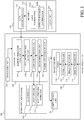
- FIG. 1 illustrates a configuration of a projector 100 that serves as an image projection apparatus according to a first embodiment of the present invention.
- a projection lens unit (simply referred to as a projection lens hereinafter) 160 is detachably (interchangeably) attached to the projector 100.
- the projector 100 includes a light source unit 120, an image former 130, a lens shift mechanism 140 as a shifter, a controller 150, and an operation unit 101.
- the light source unit 120 includes a light source and a light source driving circuit.
- the light source may use a discharge lamp such as a xenon lamp and a high-pressure mercury lamp, or a semiconductor light source such as an LED or a laser diode (LD).
- the light source driving circuit performs a light source turning on/off control and brightness control under control of the controller 150.
- the illumination light emitted from the light source unit 120 is guided to a light modulation panel 134 in the image former 130 through an unillustrated optical system.
- the image former 130 includes a signal processor 131, an image processor 132, and a panel controller 133, in addition to a light modulation panel 134 serving as a light modulator.
- the signal processor 131 performs signal processing, such as a synchronization separation and an A/D conversion, for the input image signal VS from the outside.
- the image signal VS includes a variety of image (or video) signals such as an HDMI (registered trademark) signal, a DVI signal, and a VGA signal output from an image supply device such as a personal computer, a DVD player, and a television tuner.
- the image processor 132 performs image processing such as an interlace/progressive conversion, a frame rate conversion, an aspect ratio conversion, a color correction, and a resolution conversion for the image signal processed and output from the signal processor 131.
- the panel controller 133 drives the light modulation panel 134 in accordance with the image signal processed and output from the image processor 132. Thereby, the illumination light (incident light) guided to the light modulation panel 134 is modulated according to the image signal to generate image light.
- the light modulation panel 134 is a reflection type or transmission type liquid crystal panel, a digital micromirror device, or the like. Image light from the light modulation panel 134 is projected onto a projection surface such as an unillustrated screen via a lens unit (projection optical system) 163 in the projection lens 160. Thereby, a projection image is displayed on the projection surface.
- the operation unit 101 accepts an operation of an operation member, such as a button provided on the projector 100, by a user or an operation signal from a remote controller, and outputs a control instruction to the controller 150.
- the controller 150 includes a microcomputer including a CPU, a ROM, a RAM, and the like.
- the controller 150 controls the light source unit 120, the image former 130, and the lens shift mechanism 140 using the RAM as a work memory in accordance with the control instruction or in accordance with a computer program recorded in advance in the ROM.
- the controller 150 communicates with a lens microcomputer 161 in the projection lens 160.
- a lens shift mechanism 140 includes a lens mount 141, a shift driver 142, and a shift position detector 143.
- the lens mount 141 is a portion of the projector 100 to which the projection lens 160 is detachably attached, mechanically holds the attached projection lens 160, and is electrically connected to the projector 100 (controller 150).
- the lens shift mechanism 140 is a mechanism that shifts the lens mount 141 or the projection lens (one unit) 160 attached to it in a shift direction orthogonal to the optical axis of the lens unit 163 relative to the light modulation panel (the other unit) 134. Shifting the projection lens 160 can move the position of the projection image (projection position of the image light) on the projection surface.
- the shift driver 142 includes a shift actuator such as a DC motor and a stepping motor and its drive circuit, and drives the lens mount 141 in the shift direction by the drive force of the shift actuator.
- the shift position detector 143 includes a variable resistor that can output an electrical signal corresponding to a shift amount between the center position of the light modulation panel 134 and the optical axis position of the projection lens 160 (lens unit 163).
- the shift position detector 143 sets to reference positions (first positions) the positions of the lens mount 141 and the projection lens 160 where the shift amount is 0 in the shift direction of the optical axis position of the projection lens 160 relative to the center position of the light modulation panel 134. Then, shift amounts for each shift direction (horizontal direction and vertical direction) of the lens mount 141 and the projection lens 160 from the reference positions are detected as shift positions for each shift direction (referred to as a lens shift position hereinafter).
- controller 150 controls the shift actuator via the shift driver 142 in shifting the projection lens 160 to the target lens shift position so that a difference between the lens shift position detected by the shift position detector 143 and the target lens shift position becomes small (to zero).
- the shift position detector 143 may detect the lens shift position from a driving amount of the shift actuator of the shift driver 142 (such as the number of driving pulses applied to the stepping motor), or may detect the lens shift position using a position sensor other than a variable resistor such as an encoder.
- While this embodiment has shifted the entire projection lens 160 (lens unit 163) to move the position of the projection image, but may move the position of the projection image on the projection surface by shifting part of the lenses included in the lens unit 163.
- the position of the projection image may be moved by shifting the light modulation panel (one unit) 134 relative to the projection lens (the other unit) 160. In other words, (at least part of) the projection lens 160 and the light modulation panel 134 may be shifted relative to each other.
- the controller 150 includes a lens information storage unit 151, a lens interchange detector 152, a lens shift controller 153, a determination unit 154, and a panel size storage unit 155.
- the projection lens 160 includes a lens memory 162 as a storage unit in addition to the lens unit 163 and the lens microcomputer 161 described above.
- the lens information storage unit 151 includes a nonvolatile memory such as an EEPROM, and stores lens information (162A) of the projection lens 160 attached to the projector 100.
- the lens interchange detector 152 acquires lens information 162A of the projection lens 160 stored in the lens memory 162 through a communication with the lens microcomputer 161, and stores it in the lens information storage unit 151.
- the lens information 162A is information for identifying the projection lens 160, and includes a model, a name, a model number, a serial number, and the like of the projection lens 160.
- the lens information 162A may include optical information such as a focal length and an F-number of the lens unit 163 and effective range information described later.
- the projection lens 160 may be identified by providing a plurality of electrical contacts on each of the lens mount 141 and the projection lens 160, and by determining whether each of the plurality of electrical contacts on the lens mount 141 is in an electrically open state or a short state.
- the lens memory 162 may include a noncontact IC tag such as an RFID (Radio Frequency IDentifier) and store the lens information, and the projector 100 may acquire the lens information by wirelessly communicating with the noncontact IC tag.
- RFID Radio Frequency IDentifier
- the lens interchange detector 152 acquires lens information from the newly attached projection lens.
- the newly acquired lens information is compared with the lens information of the projection lens 160 stored in the lens information storage unit 151, and if they coincide with each other, an attachment of a projection lens 160' different from the projection lens 160 (the lens interchange) is detected and the lens shift controller 153 may be notified of it.
- the lens unit 163, the lens microcomputer 161, and the lens memory 162 are also provided to the newly attached projection lens 160'. Further, assume that the lens information 162A and effective range information 162B of the projection lens 160' are stored in the lens memory 162.
- the panel size storage unit 155 includes a nonvolatile memory, such as an EEPROM, and stores the size of the light modulation panel 134.
- the size of the light modulation panel 134 may be at least one of a diagonal length and an aspect ratio, a long side length, a short side length, an area and a length of one side, and the like.
- the size may be the size of an effective modulation area where the illumination light is actually modulated in the light modulation panel 134 or an area set inward by a margin.
- the determination unit 154 reads the size of the light modulation panel 134 from the panel size storage unit 155 and acquires the lens shift position detected by the shift position detector 143.
- the determination unit 154 acquires effective range information 162B from the lens memory 162 through a communication with the lens microcomputer 161.
- the effective range information 162B is unique information for each projection lens, and indicates an effective range (referred to as an effective lens range hereinafter) in the lens unit 163 of the projection lens.
- the effective lens range is a range on a plane (referred to as a lens incident plane hereinafter) orthogonal to the optical axis of the lens unit 163 at the lens position closest to the light modulation panel in the lens unit 163.
- the effective range of the lens is a range in which a good non-chipped projection image (smaller than a predetermined amount) is displayed on the projection surface when all image light from the light modulation panel 134 is incident on it.
- the determination unit 154 calculates a range in which the image light from the light modulation panel 134 passes on the above lens incident plane (referred to as an image light passing range hereinafter). Then, the determination unit 154 compares the calculated image light passing range with the effective lens range indicated by the effective range information 162B. If the image light passing range is located within the effective lens range, all image light from the light modulation panel 134 passes through the lens unit 163, reaches the projection surface, and provides a good display of the projection image.
- the projection image displayed on the projection surface has a chip exceeding a predetermined amount.
- the lens unit 163 includes a resin lens and the barrel temperature rises because the barrel shields the image light, the barrel and the optical element may be thermally deformed.
- the effective lens range it is necessary to set the effective lens range so as to prevent the image light from being shielded.
- the controller 150 controls (permits) a shift of the projection lens 160 relative to (the image light from) the light modulation panel 134 within a shift permissible range that is a range of a lens shift position where the entire image light passing range falls within the effective lens range.
- controlling the shift of the projection lens 160 within the shift permissible range is equivalent with controlling the position of the effective lens range so as to include the entire image light passing range.
- the effective range information 162B is information used to position the projection lens 160 within the shift permissible range.
- the determination unit 154 determines that at least part of the image light passing range is located outside the effective lens range (or the lens shift position is located outside the shift permissible range)
- the determination unit 154 notifies the lens shift controller 153 of this result.
- the relationship between the image light passing range and the effective lens range and the determination method by the determination unit 154 will be described in detail later.
- the effective lens range is not limited to the range in which the projection image is hardly chipped (the image light is hardly shielded) as described above, but may be a range in which an amount of the distortion, the chromatic aberration, the peripheral luminance reduction, or the like in the projection image is smaller than a predetermined amount.
- the effective lens range may be a range in which a predetermined brightness is obtained in at least specific part (such as central part) of the projection image.
- the effective lens range may be a range where a predetermined brightness can be obtained in the darkest part of the projection image.
- the effective lens range is determined according to a condition relating to the image quality such as chipping, distortion, chromatic aberration, and brightness of the projection image.
- the effective lens range may be a range according to the characteristics of the projector 100 such as a light emission amount of the light source unit 120 and a drive limit range of the lens shift mechanism 140.
- the lens shift controller 153 controls the shift driving unit 142 to shift the mount 141.
- the lens shift controller 153 controls the shift driver 142 so that the image light passing range is located within the effective lens range or the projection lens enters the shift permissible range when the lens interchange detector 152 detects the lens interchange and the determination unit 154 determines the outside of the effective range. Details of this control will be described later.
- the range in which the image light can pass the lens unit 163 without being shielded is similar to the image circle of the lens unit 163, and the shape is also similar to the shape of the image circle.
- the effective lens range is the image circle of the lens unit 163, and the lens shift position is adjusted so that the image light can pass the image circle.
- the image circle of the lens unit 163 is determined by the diameter of the lens closest to the light modulation panel in the lens unit 163 or the aperture diameter in the lens unit 163.
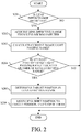
- a flowchart in FIG. 2 illustrates processing performed by the controller 150 during the lens interchange.
- the controller 150 executes this processing according to a computer program before the projector 100 starts the image projection in response to a user operation on the operation unit 101.
- the controller 150 determines whether lens interchange has been detected by the lens interchange detector 152. If the lens interchange is detected, the controller 150 proceeds to the step S202, and if it is not detected, the flow ends.
- the controller 150 acquires effective range information 162B of the projection lens 160' attached after the lens interchange by the communication with the lens microcomputer 161.
- the controller 150 causes the lens information storage unit 151 to store the lens information 162A and the effective range information 162B of the projection lens 160'.
- the controller 150 calculates the image light passing range using the size of the light modulation panel 134 read from the panel size storage unit 155 and the lens shift position detected by the shift position detector 143.
- FIG. 3 illustrates an optical path from the light source unit 120 to a projection surface 303 in this embodiment.
- the illumination light emitted from the light source unit 120 is modulated by the light modulation panel 134, becomes image light 301, passes through the lens unit 163, and forms a projection image 304 on the projection surface 303.
- the lens unit 163 actually includes a plurality of lenses, FIG. 3 illustrates a single lens.
- the lens unit 163 has an image circle as an effective lens range in which the incident image light 301 can pass through the inside of the lens unit 163 with almost no chipping, peripheral brightness reduction, distortion, and chromatic aberration of the projection image more than the permissible level.
- FIG. 4 illustrates image circles 400A and 400B of the lens unit 163 of two different types of projection lenses on the lens incident plane.
- the image circle 400A is an image circle of the projection lens attached on the projector 100 before the lens is interchanged
- the image circle 400B is an image circle of the newly attached interchanged projection lens. Both of these image circles 400A and 400B are circular ranges centering on the optical axis 300 of the lens unit 163.
- a rectangular solid line frame indicates an image light passing range 305 through which the image light 301 illustrated in FIG. 3 passes on the lens incident plane.
- the controller 150 controls the lens shift mechanism 140 (lens shift position) so that the entire image light passing range 305 is positioned inside the image circle 400B as indicated by an alternate long and short dash line frame.
- the controller 150 controls the lens shift mechanism 140 so as to shift the projection lens to a second position and stop it there that can be reached by a shift amount smaller than a shift amount to the first position (home or reset position) that is the reference position relative to the light modulation panel 134.
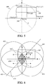
- FIG. 5 sets the position of the optical axis 300 on the lens incident plane to an origin O(0, 0), the vertical direction to the y-axis direction, and the horizontal direction to the x-axis direction.
- the shift position detector 143 detects the center position P(x p , y p ) of the image light passing range 305.
- H is a width of the image light passing range 305 calculated by the controller 150 from the size of the light modulation element 134 acquired from the panel size storage unit 155
- V is a height.
- the determination unit 154 calculates the coordinates of the vertex P n by the following expression (1) using the center position P(x p , y p ), the width H, and the height V of the image light passing range 305.
- the determination unit 154 determines whether or not at least part of the image light passing range 305 is located outside the image circle 400 that is the effective lens range.
- the image circle 400 illustrated in FIG. 5 is a circle having a radius R with the origin O as the center.
- the determination unit 154 can determine whether or not the vertex P n obtained in the step S203 is located outside the image circle 400, by determining whether or not the following expression (2) is satisfied.
- R ⁇ x n 2 + y n 2 ⁇ 0 n 1 , 2 , 3 , 4 ,
- the controller 150 proceeds to the step S205. If not (or when the entire image light passing range 305 is located in the image circle 400), the controller 140 ends this processing.
- the controller 150 determines a destination of the image circle 400 relative to the image light passing range 305. More specifically, the controller 150 calculates the lens shift position that position the entire image light passing range 305 in the image circle 400 by the shortest shift amount based on the current lens shift position, the origin O and the radius R of the image circle 400, and sets the position to the target lens shift position as the second position.
- This configuration can position the entire image light passing range 305 in the effective lens range more quickly than the interchanged projection lens shifted to the above home position, and can shorten a time from the lens interchange to a good display of a projection image.
- FIG. 6 illustrates a method for calculating a target lens shift position.
- the projection lens shifts and the image circle moves relative to the image light passing range 305, but the following description assumes that the image light passing range 305 moves relative to the image circle.
- the controller 150 finds a target range 600 in which the center position P(x p , y p ) of the image light passing range 305 can be located so that the image light passing range 305 does not protrude from the image circle.
- the coordinate of each point in FIG. 6 is defined as Pn'(xn', yn').
- a circle having a radius R centered on the point P1' is defined as a circle 401.
- circles having a radius R centered on the points P2', P3', and P4' are respectively defined as a circle 402, a circle 403, and a circle 404.
- FIG. 6 an area where the inner areas of the circles 401 to 404 overlap each other is indicated by hatching, and this area is the target range 600 described above.
- a coordinate (x n ', y n ') of the point Pn' is expressed by the following expression (3), and the boundary of the target range 600 is expressed by the following expression (4).
- the controller 150 finds a target position where the center position P(x p , y p ) of the image light passing range 305 can be located by the shortest shift amount of the projection lens within the target range 600.
- a straight line 610 connecting the center position P(x p , y p ) of the image light passing range 305 to the origin O where the optical axis 300 of the lens unit 163 is located is expressed by the following expression (5).
- y y p x p x
- the point closest to the center position P(x p , y p ) of the image light passing range 305 is the target position 605 among intersections between the straight line 610 and the boundary of the target range 600.
- a description will now be given of a method of calculating the target position 605 when the projection lens is shifted to a first quadrant where x p ⁇ 0 and y p ⁇ 0 relative to the origin O. Even when the projection lens is shifted to the second to fourth quadrants, the target position can be similarly calculated using the center position P(x p , y p ) of the image light passing range 305, the size of the light modulation panel 134, and the expressions (3) to (5).
- a coordinate (x s , y s ) of the target position 605 when the projection lens is shifted to the first quadrant is expressed by the following expression (6).
- x s ⁇ b + b 2 ⁇ 4 ac 2
- the controller 150 that has calculated the target position 605 notifies the lens shift controller 153 of the target position 605.
- an image light passing range 305' having the target position 605 as the center position is indicated by a dotted line.
- the lens shift controller 153 calculates a target lens shift position for positioning the center position P' of the image light passing range 305' at the target position 605, as illustrated in FIG. 7 . More specifically, the lens shift controller 153 calculates - ⁇ x and - ⁇ y indicating the direction and distance from the center position P of the image light passing range 305 to the center position P' of the image light passing range 305', adds + ⁇ x and + ⁇ y having reversed signs to the current lens shift position detected in the step S203, and calculates the target lens shift position. Then, the lens shift controller 153 controls the shift driver 142 to shift the projection lens to the target lens shift position. Thereby, the entire image light passing range 305' can be located in the image circle 400 by the shortest shift amount of the projection lens.
- This embodiment can shorten the time from the lens interchange to a good display of a projection image.
- FIG. 8 illustrates a configuration of a projector 100A according to a second embodiment of the present invention.
- Those elements in the projector 100A in this embodiment which are corresponding elements in the projector 100 of the first embodiment, will be designated by the same reference numerals, and a description thereof will be omitted.
- the projector 100A includes a lens information input unit 170 as a storage unit.
- the lens information input unit 170 stores the lens information 162A and effective range information 162B of a plurality of types of projection lenses attachable to the projector 100A.
- the lens information input unit 170 has a function that allows the user to input a projection lens to be attached to the projector 100A among the plurality of types of projection lenses by a user's button operation, touch panel operation, and remote control operation. At this time, an input image of the projection lens may be displayed by a monitor provided in the projector 100A or an OSD projected by the projector.
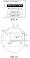
- FIG. 9 illustrates an input screen (lens selection menu) of a projection lens.
- the lens selection menu displays "wide-angle lens 1," “wide-angle lens 2,” “zoom lens 1,” and “zoom lens 2" as a plurality of types of projection lenses.
- FIG. 9 illustrates that the user inputs the "wide-angle lens 01.”
- the lens memory 162 storing the lens information 162A and the effective range information 162B is not provided to the projection lens 160A unlike the first embodiment, and the controller 150 and the lens microcomputer 161 do not communicate with each other.
- the lens information storage unit 151 stores the lens information 162A of the projection lens that is attached before the lens interchange.
- the lens information input unit 170 notifies the lens interchange detector 152 of the lens information 162A of the projection lens, and notifies the determination unit 154 of the effective range information 162B.
- the lens interchange detector 152 compares the lens information 162A stored in the lens information storage unit 151 with the lens information 162A notified from the lens information input unit 170, and determines the lens interchange, by determining whether or not they coincide with each other.
- the input of the projection lens used after the lens interchange by the user may be after the lens interchange as described above or before the lens interchange.
- the user In inputting the projection lens to be used after the lens exchange, before the lens interchange, the user notifies the controller 150 through the operation unit 101 of the lens interchange.
- the controller 150 reads out the lens information 162A of the currently attached projection lens from the lens information storage unit 151 and notifies the lens interchange detector 152 of the result.
- the lens information input unit 170 notifies the lens interchange detector 152 of the lens information 162A of the projection lens to be used after the lens interchange.
- the lens interchange detector 152 compares the lens information 162A of the currently installed projection lens with the lens information 162A of the projection lens used after the lens interchange, and determines that it will be interchanged with a different type of projection lens from the currently attached projection lens, if they do not coincide with each other. In this case, the lens information input unit 170 notifies the determination unit 154 of the effective range information 162B of the projection coefficient distribution lens used after the lens interchange.
- an interlock switch for detecting the attachment and detachment of the projection lens 160 is provided to the lens mount 141 of the projector 100, and when the interchange of the projection lens is detected by the interlock switch, a lens selection menu of the projection lens may be displayed.
- the control of the lens shift mechanism 140 when the determination unit 154 determines that it is out of the effective range is the same as that of the first embodiment.
- the first embodiment has discussed the effective lens range that is the image circle of the lens unit 163.
- the effective lens range may be a range set inside the image circle.
- FIG. 10 illustrates a range 1000 in which the brightness of the projection image is equal to or higher than a predetermined brightness inside the image circle 400 on the lens incident plane orthogonal to the optical axis 300.
- this range 100 is the effective lens range.
- Part of the image light passing range 305 sticks into the effective lens range 100 and outside the image circle 400.
- FIG. 11 illustrates how the controller 150 (determination unit 154) determines whether or not the image light passing range 305 protrudes outside the effective lens range 1000.
- a vector formed by the vertex t mN of T m and one point P' M of the vertex of the image light passing range 305 is expressed by the following expression (7).
- t mN P ⁇ M ⁇ x M ⁇ ⁇ x tmN , y M ⁇ ⁇ y tmN
- t ma t mN ⁇ x mN ⁇ x ma , y mN ⁇ x ma
- t mN P ⁇ M ⁇ ⁇ t ma t mN ⁇ z x M ⁇ ⁇ x tmN ⁇ y tmN ⁇ x tma ⁇ y M ⁇ ⁇ y tmN ⁇ x tmN ⁇ x tma
- whether or not the vertex P' M of the image light passing range 305 protrudes outside the triangle T m may be determined by determining whether the following expression (10) is established with at least one N. t mN P ⁇ M ⁇ ⁇ t ma t mN ⁇ z ⁇ 0
- At least part of the image light passing range 305 can be determined to be located outside of the effective lens range 1000. For example, since P' 1 satisfies the expression (10) with at least one N for all triangles T m , it can be determined that at least part of the image light passing range 305 is located outside the effective lens range 1000.
- the first embodiment has discussed the controller 150 calculating the target lens shift position movable by the shortest shift amount.
- FIG. 10 illustrates an image light passing range 305' corresponding to the target lens shift position that can be reached by the shortest shift amount, and an image light passing range 305" corresponding to the target lens shift position that can be reached only by the horizontal shift.
- the projection lens By shifting the projection lens to the target lens shift position that can be reached only by the horizontal shift, the projection lens can be shifted to the target lens shift position in the shortest time even if the shift amount is not the shortest. As a result, it is possible to make shorter the time from the lens interchange to the good display of the projection image.
- Each of the above embodiments can start a good image projection in a short time when the projection lens unit is interchanged.
- Embodiment(s) of the present invention can also be realized by a computer of a system or apparatus that reads out and executes computer executable instructions (e.g., one or more programs) recorded on a storage medium (which may also be referred to more fully as a 'non-transitory computer-readable storage medium') to perform the functions of one or more of the above-described embodiment(s) and/or that includes one or more circuits (e.g., application specific integrated circuit (ASIC)) for performing the functions of one or more of the above-described embodiment(s), and by a method performed by the computer of the system or apparatus by, for example, reading out and executing the computer executable instructions from the storage medium to perform the functions of one or more of the above-described embodiment(s) and/or controlling the one or more circuits to perform the functions of one or more of the above-described embodiment(s).
- computer executable instructions e.g., one or more programs
- a storage medium which may also be referred to more fully as
- the computer may comprise one or more processors (e.g., central processing unit (CPU), micro processing unit (MPU)) and may include a network of separate computers or separate processors to read out and execute the computer executable instructions.
- the computer executable instructions may be provided to the computer, for example, from a network or the storage medium.
- the storage medium may include, for example, one or more of a hard disk, a random-access memory (RAM), a read only memory (ROM), a storage of distributed computing systems, an optical disk (such as a compact disc (CD), digital versatile disc (DVD), or Blu-ray Disc (BD)TM), a flash memory device, a memory card, and the like.
Landscapes
- Physics & Mathematics (AREA)
- General Physics & Mathematics (AREA)
- Engineering & Computer Science (AREA)
- Multimedia (AREA)
- Signal Processing (AREA)
- Geometry (AREA)
- Optics & Photonics (AREA)
- Projection Apparatus (AREA)
- Transforming Electric Information Into Light Information (AREA)
Abstract
Description
- The present invention relates to an image projection apparatus (referred to as a projector hereinafter) that can interchange and shift and a projection lens.
- In a projector configured to shift a projection lens and to move a projection image on a screen, the projection lens may shield image light from a light modulation element, such as a liquid crystal panel, unless a shift position of the projection lens is correctly adjusted relative to the light modulation element. Thereby, the periphery of the projection image becomes dark or chipped.
- Japanese Patent No. ("
JP") 5911285 JP 5744566 - The projector disclosed in
JP 5911285 - The projector disclosed in
JP 5744566 - The present invention provides a projector that can start a good image projection in a short time when the projection lens unit to be interchanged is located outside of the shift permissible range.
- The present invention in its first aspect provides an image projection apparatus as specified in
claims 1 to 13. - The present invention in its second aspect provides a control method as specified in claim 14.
- The present invention in its third aspect provides a computer program as specified in claim 15.
- Further features of the present invention will become apparent from the following description of exemplary embodiments with reference to the attached drawings.
-
-
FIG. 1 is a block diagram showing a configuration of a projector according to a first embodiment of the present invention. -
FIG. 2 is a flowchart illustrating processing when a projection lens is interchanged according to the first embodiment. -
FIG. 3 illustrates an optical path according to the first embodiment. -
FIG. 4 explains an image circle of the projection lens according to the first embodiment. -
FIG. 5 illustrates a method for calculating an area of the projection lens through which image light passes according to the first embodiment. -
FIG. 6 illustrates a method for determining a target lens shift position of the projection lens according to the first embodiment. -
FIG. 7 explains the image light after the projection lens is shifted to the target lens shift position according to the first embodiment. -
FIG. 8 is a block diagram showing a configuration of a projector according to a second embodiment of the present invention. -
FIG. 9 illustrates a lens designation menu according to the second embodiment. -
FIG. 10 explains a range in which a projection image can be projected with a predetermined light amount or larger according to the second embodiment. -
FIG. 11 illustrates a method for determining whether or not an image light passing range sticks into an effective lens range according to a variation of the embodiment. - Referring now to the accompanying drawings, a description will be given of embodiments according to the present invention.
-
FIG. 1 illustrates a configuration of aprojector 100 that serves as an image projection apparatus according to a first embodiment of the present invention. A projection lens unit (simply referred to as a projection lens hereinafter) 160 is detachably (interchangeably) attached to theprojector 100. - The
projector 100 includes alight source unit 120, an image former 130, alens shift mechanism 140 as a shifter, acontroller 150, and anoperation unit 101. Thelight source unit 120 includes a light source and a light source driving circuit. The light source may use a discharge lamp such as a xenon lamp and a high-pressure mercury lamp, or a semiconductor light source such as an LED or a laser diode (LD). The light source driving circuit performs a light source turning on/off control and brightness control under control of thecontroller 150. The illumination light emitted from thelight source unit 120 is guided to alight modulation panel 134 in the image former 130 through an unillustrated optical system. - The image former 130 includes a
signal processor 131, animage processor 132, and apanel controller 133, in addition to alight modulation panel 134 serving as a light modulator. Thesignal processor 131 performs signal processing, such as a synchronization separation and an A/D conversion, for the input image signal VS from the outside. The image signal VS includes a variety of image (or video) signals such as an HDMI (registered trademark) signal, a DVI signal, and a VGA signal output from an image supply device such as a personal computer, a DVD player, and a television tuner. Theimage processor 132 performs image processing such as an interlace/progressive conversion, a frame rate conversion, an aspect ratio conversion, a color correction, and a resolution conversion for the image signal processed and output from thesignal processor 131. Thepanel controller 133 drives thelight modulation panel 134 in accordance with the image signal processed and output from theimage processor 132. Thereby, the illumination light (incident light) guided to thelight modulation panel 134 is modulated according to the image signal to generate image light. Thelight modulation panel 134 is a reflection type or transmission type liquid crystal panel, a digital micromirror device, or the like. Image light from thelight modulation panel 134 is projected onto a projection surface such as an unillustrated screen via a lens unit (projection optical system) 163 in theprojection lens 160. Thereby, a projection image is displayed on the projection surface. - The
operation unit 101 accepts an operation of an operation member, such as a button provided on theprojector 100, by a user or an operation signal from a remote controller, and outputs a control instruction to thecontroller 150. Thecontroller 150 includes a microcomputer including a CPU, a ROM, a RAM, and the like. Thecontroller 150 controls thelight source unit 120, the image former 130, and thelens shift mechanism 140 using the RAM as a work memory in accordance with the control instruction or in accordance with a computer program recorded in advance in the ROM. Thecontroller 150 communicates with alens microcomputer 161 in theprojection lens 160. - A
lens shift mechanism 140 includes alens mount 141, ashift driver 142, and ashift position detector 143. Thelens mount 141 is a portion of theprojector 100 to which theprojection lens 160 is detachably attached, mechanically holds the attachedprojection lens 160, and is electrically connected to the projector 100 (controller 150). Thelens shift mechanism 140 is a mechanism that shifts thelens mount 141 or the projection lens (one unit) 160 attached to it in a shift direction orthogonal to the optical axis of thelens unit 163 relative to the light modulation panel (the other unit) 134. Shifting theprojection lens 160 can move the position of the projection image (projection position of the image light) on the projection surface. Theshift driver 142 includes a shift actuator such as a DC motor and a stepping motor and its drive circuit, and drives thelens mount 141 in the shift direction by the drive force of the shift actuator. - The
shift position detector 143 includes a variable resistor that can output an electrical signal corresponding to a shift amount between the center position of thelight modulation panel 134 and the optical axis position of the projection lens 160 (lens unit 163). Theshift position detector 143 sets to reference positions (first positions) the positions of thelens mount 141 and theprojection lens 160 where the shift amount is 0 in the shift direction of the optical axis position of theprojection lens 160 relative to the center position of thelight modulation panel 134. Then, shift amounts for each shift direction (horizontal direction and vertical direction) of thelens mount 141 and theprojection lens 160 from the reference positions are detected as shift positions for each shift direction (referred to as a lens shift position hereinafter). - When the
controller 150 controls the shift actuator via theshift driver 142 in shifting theprojection lens 160 to the target lens shift position so that a difference between the lens shift position detected by theshift position detector 143 and the target lens shift position becomes small (to zero). - The
shift position detector 143 may detect the lens shift position from a driving amount of the shift actuator of the shift driver 142 (such as the number of driving pulses applied to the stepping motor), or may detect the lens shift position using a position sensor other than a variable resistor such as an encoder. - While this embodiment has shifted the entire projection lens 160 (lens unit 163) to move the position of the projection image, but may move the position of the projection image on the projection surface by shifting part of the lenses included in the
lens unit 163. The position of the projection image may be moved by shifting the light modulation panel (one unit) 134 relative to the projection lens (the other unit) 160. In other words, (at least part of) theprojection lens 160 and thelight modulation panel 134 may be shifted relative to each other. - The
controller 150 includes a lensinformation storage unit 151, alens interchange detector 152, alens shift controller 153, adetermination unit 154, and a panelsize storage unit 155. Theprojection lens 160 includes alens memory 162 as a storage unit in addition to thelens unit 163 and thelens microcomputer 161 described above. - The lens
information storage unit 151 includes a nonvolatile memory such as an EEPROM, and stores lens information (162A) of theprojection lens 160 attached to theprojector 100. When theprojection lens 160 is attached on theprojector 100, thelens interchange detector 152 acquireslens information 162A of theprojection lens 160 stored in thelens memory 162 through a communication with thelens microcomputer 161, and stores it in the lensinformation storage unit 151. - The
lens information 162A is information for identifying theprojection lens 160, and includes a model, a name, a model number, a serial number, and the like of theprojection lens 160. Thelens information 162A may include optical information such as a focal length and an F-number of thelens unit 163 and effective range information described later. Alternatively, theprojection lens 160 may be identified by providing a plurality of electrical contacts on each of thelens mount 141 and theprojection lens 160, and by determining whether each of the plurality of electrical contacts on thelens mount 141 is in an electrically open state or a short state. Thelens memory 162 may include a noncontact IC tag such as an RFID (Radio Frequency IDentifier) and store the lens information, and theprojector 100 may acquire the lens information by wirelessly communicating with the noncontact IC tag. - When the
current projection lens 160 is detached and a new projection lens is attached to theprojector 100, thelens interchange detector 152 acquires lens information from the newly attached projection lens. The newly acquired lens information is compared with the lens information of theprojection lens 160 stored in the lensinformation storage unit 151, and if they coincide with each other, an attachment of a projection lens 160' different from the projection lens 160 (the lens interchange) is detected and thelens shift controller 153 may be notified of it. - In the following description, assume that the
lens unit 163, thelens microcomputer 161, and thelens memory 162 are also provided to the newly attached projection lens 160'. Further, assume that thelens information 162A andeffective range information 162B of the projection lens 160' are stored in thelens memory 162. - The panel
size storage unit 155 includes a nonvolatile memory, such as an EEPROM, and stores the size of thelight modulation panel 134. The size of thelight modulation panel 134, as used herein, may be at least one of a diagonal length and an aspect ratio, a long side length, a short side length, an area and a length of one side, and the like. In addition, the size may be the size of an effective modulation area where the illumination light is actually modulated in thelight modulation panel 134 or an area set inward by a margin. - The
determination unit 154 reads the size of thelight modulation panel 134 from the panelsize storage unit 155 and acquires the lens shift position detected by theshift position detector 143. Thedetermination unit 154 acquireseffective range information 162B from thelens memory 162 through a communication with thelens microcomputer 161. - The
effective range information 162B is unique information for each projection lens, and indicates an effective range (referred to as an effective lens range hereinafter) in thelens unit 163 of the projection lens. The effective lens range is a range on a plane (referred to as a lens incident plane hereinafter) orthogonal to the optical axis of thelens unit 163 at the lens position closest to the light modulation panel in thelens unit 163. The effective range of the lens is a range in which a good non-chipped projection image (smaller than a predetermined amount) is displayed on the projection surface when all image light from thelight modulation panel 134 is incident on it. - The
determination unit 154 calculates a range in which the image light from thelight modulation panel 134 passes on the above lens incident plane (referred to as an image light passing range hereinafter). Then, thedetermination unit 154 compares the calculated image light passing range with the effective lens range indicated by theeffective range information 162B. If the image light passing range is located within the effective lens range, all image light from thelight modulation panel 134 passes through thelens unit 163, reaches the projection surface, and provides a good display of the projection image. On the other hand, if at least part of the image light passing range sticks into the effective lens range, at least part of the image light from thelight modulation panel 134 does not reach the target surface because it does not enter thelens unit 163 or is shielded by the barrel (or a light shielding member) that holds an optical element such as a mirror or the like in thelens unit 163. As a result, the projection image displayed on the projection surface has a chip exceeding a predetermined amount. - When the
lens unit 163 includes a resin lens and the barrel temperature rises because the barrel shields the image light, the barrel and the optical element may be thermally deformed. Thus, from the viewpoint of protecting theprojection lens 160 as well as the chip of the projection image, it is necessary to set the effective lens range so as to prevent the image light from being shielded. - In this embodiment, the
controller 150 controls (permits) a shift of theprojection lens 160 relative to (the image light from) thelight modulation panel 134 within a shift permissible range that is a range of a lens shift position where the entire image light passing range falls within the effective lens range. In other words, controlling the shift of theprojection lens 160 within the shift permissible range is equivalent with controlling the position of the effective lens range so as to include the entire image light passing range. Theeffective range information 162B is information used to position theprojection lens 160 within the shift permissible range. - If the
determination unit 154 determines that at least part of the image light passing range is located outside the effective lens range (or the lens shift position is located outside the shift permissible range), thedetermination unit 154 notifies thelens shift controller 153 of this result. The relationship between the image light passing range and the effective lens range and the determination method by thedetermination unit 154 will be described in detail later. - The effective lens range is not limited to the range in which the projection image is hardly chipped (the image light is hardly shielded) as described above, but may be a range in which an amount of the distortion, the chromatic aberration, the peripheral luminance reduction, or the like in the projection image is smaller than a predetermined amount. The effective lens range may be a range in which a predetermined brightness is obtained in at least specific part (such as central part) of the projection image. The effective lens range may be a range where a predetermined brightness can be obtained in the darkest part of the projection image. Thus, the effective lens range is determined according to a condition relating to the image quality such as chipping, distortion, chromatic aberration, and brightness of the projection image. The effective lens range may be a range according to the characteristics of the
projector 100 such as a light emission amount of thelight source unit 120 and a drive limit range of thelens shift mechanism 140. - The
lens shift controller 153 controls theshift driving unit 142 to shift themount 141. Thelens shift controller 153 controls theshift driver 142 so that the image light passing range is located within the effective lens range or the projection lens enters the shift permissible range when thelens interchange detector 152 detects the lens interchange and thedetermination unit 154 determines the outside of the effective range. Details of this control will be described later. - The range in which the image light can pass the
lens unit 163 without being shielded is similar to the image circle of thelens unit 163, and the shape is also similar to the shape of the image circle. In this embodiment, the effective lens range is the image circle of thelens unit 163, and the lens shift position is adjusted so that the image light can pass the image circle. The image circle of thelens unit 163 is determined by the diameter of the lens closest to the light modulation panel in thelens unit 163 or the aperture diameter in thelens unit 163. - A flowchart in
FIG. 2 illustrates processing performed by thecontroller 150 during the lens interchange. Thecontroller 150 executes this processing according to a computer program before theprojector 100 starts the image projection in response to a user operation on theoperation unit 101. - In the step S201, the
controller 150 determines whether lens interchange has been detected by thelens interchange detector 152. If the lens interchange is detected, thecontroller 150 proceeds to the step S202, and if it is not detected, the flow ends. - In the step S202, the
controller 150 acquireseffective range information 162B of the projection lens 160' attached after the lens interchange by the communication with thelens microcomputer 161. Thecontroller 150 causes the lensinformation storage unit 151 to store thelens information 162A and theeffective range information 162B of the projection lens 160'. - In the step S203, the controller 150 (determination unit 154) calculates the image light passing range using the size of the
light modulation panel 134 read from the panelsize storage unit 155 and the lens shift position detected by theshift position detector 143. -
FIG. 3 illustrates an optical path from thelight source unit 120 to aprojection surface 303 in this embodiment. The illumination light emitted from thelight source unit 120 is modulated by thelight modulation panel 134, becomes image light 301, passes through thelens unit 163, and forms aprojection image 304 on theprojection surface 303. Although thelens unit 163 actually includes a plurality of lenses,FIG. 3 illustrates a single lens. Thelens unit 163 has an image circle as an effective lens range in which the incident image light 301 can pass through the inside of thelens unit 163 with almost no chipping, peripheral brightness reduction, distortion, and chromatic aberration of the projection image more than the permissible level. -
FIG. 4 illustrates image circles 400A and 400B of thelens unit 163 of two different types of projection lenses on the lens incident plane. Theimage circle 400A is an image circle of the projection lens attached on theprojector 100 before the lens is interchanged, and theimage circle 400B is an image circle of the newly attached interchanged projection lens. Both of theseimage circles optical axis 300 of thelens unit 163. A rectangular solid line frame indicates an imagelight passing range 305 through which theimage light 301 illustrated inFIG. 3 passes on the lens incident plane. - Since the entire image
light passing range 305 is located inside theimage circle 400A before the lens interchange, the image light from thelight modulation panel 134 passes through thelens unit 163 and reaches the projection surface without being shielded. On the other hand,part 401 of the imagelight passing range 305 sticks into theimage circle 400B after the lens interchange, and thus part of the image light is shielded and does not reach the projection surface. Thecontroller 150 controls the lens shift mechanism 140 (lens shift position) so that the entire imagelight passing range 305 is positioned inside theimage circle 400B as indicated by an alternate long and short dash line frame. At this time, thecontroller 150 controls thelens shift mechanism 140 so as to shift the projection lens to a second position and stop it there that can be reached by a shift amount smaller than a shift amount to the first position (home or reset position) that is the reference position relative to thelight modulation panel 134. - Referring now to
FIG. 5 , a description will be given of a calculating method of an imagelight passing range 305.FIG. 5 sets the position of theoptical axis 300 on the lens incident plane to an origin O(0, 0), the vertical direction to the y-axis direction, and the horizontal direction to the x-axis direction. Theshift position detector 143 detects the center position P(xp, yp) of the imagelight passing range 305. Assume H is a width of the imagelight passing range 305 calculated by thecontroller 150 from the size of thelight modulation element 134 acquired from the panelsize storage unit 155, and V is a height. Four vertices of the rectangular imagelight passing range 305 are defined as Pn (n = 1, 2, 3, 4) counterclockwise from the upper right vertex. In the step S203, thedetermination unit 154 calculates the coordinates of the vertex Pn by the following expression (1) using the center position P(xp, yp), the width H, and the height V of the imagelight passing range 305.
- Next, in the step S204, the
determination unit 154 determines whether or not at least part of the imagelight passing range 305 is located outside theimage circle 400 that is the effective lens range. Theimage circle 400 illustrated inFIG. 5 is a circle having a radius R with the origin O as the center. Thedetermination unit 154 can determine whether or not the vertex Pn obtained in the step S203 is located outside theimage circle 400, by determining whether or not the following expression (2) is satisfied.
- When the condition of the expression (2) is satisfied in any of n = 1, 2, 3, and 4, or when at least part of the image
light passing range 305 protrudes to the outside of theimage circle 400, thecontroller 150 proceeds to the step S205. If not (or when the entire imagelight passing range 305 is located in the image circle 400), thecontroller 140 ends this processing. - In the step S205, the
controller 150 determines a destination of theimage circle 400 relative to the imagelight passing range 305. More specifically, thecontroller 150 calculates the lens shift position that position the entire imagelight passing range 305 in theimage circle 400 by the shortest shift amount based on the current lens shift position, the origin O and the radius R of theimage circle 400, and sets the position to the target lens shift position as the second position. This configuration can position the entire imagelight passing range 305 in the effective lens range more quickly than the interchanged projection lens shifted to the above home position, and can shorten a time from the lens interchange to a good display of a projection image. -
FIG. 6 illustrates a method for calculating a target lens shift position. In reality, the projection lens shifts and the image circle moves relative to the imagelight passing range 305, but the following description assumes that the imagelight passing range 305 moves relative to the image circle. - First, the
controller 150 finds atarget range 600 in which the center position P(xp, yp) of the imagelight passing range 305 can be located so that the imagelight passing range 305 does not protrude from the image circle. Assume that the four vertices of the imagelight passing range 305 when the center position P(xp, yp) of the imagelight passing range 305 coincides with theoptical axis 300 of thelens unit 163 are Pn (n = 1, 2, 3, 4) counterclockwise. In addition, assume that the coordinate of each point inFIG. 6 is defined as Pn'(xn', yn'). A circle having a radius R centered on the point P1' is defined as acircle 401. Similarly, circles having a radius R centered on the points P2', P3', and P4' are respectively defined as acircle 402, acircle 403, and acircle 404. - In
FIG. 6 , an area where the inner areas of thecircles 401 to 404 overlap each other is indicated by hatching, and this area is thetarget range 600 described above. A coordinate (xn', yn') of the point Pn' is expressed by the following expression (3), and the boundary of thetarget range 600 is expressed by the following expression (4).

- Next, the
controller 150 finds a target position where the center position P(xp, yp) of the imagelight passing range 305 can be located by the shortest shift amount of the projection lens within thetarget range 600. Astraight line 610 connecting the center position P(xp, yp) of the imagelight passing range 305 to the origin O where theoptical axis 300 of thelens unit 163 is located is expressed by the following expression (5).
- The point closest to the center position P(xp, yp) of the image
light passing range 305 is thetarget position 605 among intersections between thestraight line 610 and the boundary of thetarget range 600. A description will now be given of a method of calculating thetarget position 605 when the projection lens is shifted to a first quadrant where xp≥0 and yp≥0 relative to the origin O. Even when the projection lens is shifted to the second to fourth quadrants, the target position can be similarly calculated using the center position P(xp, yp) of the imagelight passing range 305, the size of thelight modulation panel 134, and the expressions (3) to (5). A coordinate (xs, ys) of thetarget position 605 when the projection lens is shifted to the first quadrant is expressed by the following expression (6).
- The
controller 150 that has calculated thetarget position 605 notifies thelens shift controller 153 of thetarget position 605. InFIG. 6 , an image light passing range 305' having thetarget position 605 as the center position is indicated by a dotted line. When the processing in the step S205 is completed, thecontroller 150 proceeds to the step S206. - In the step S206, the
lens shift controller 153 calculates a target lens shift position for positioning the center position P' of the image light passing range 305' at thetarget position 605, as illustrated inFIG. 7 . More specifically, thelens shift controller 153 calculates -Δx and -Δy indicating the direction and distance from the center position P of the imagelight passing range 305 to the center position P' of the image light passing range 305', adds +Δx and +Δy having reversed signs to the current lens shift position detected in the step S203, and calculates the target lens shift position. Then, thelens shift controller 153 controls theshift driver 142 to shift the projection lens to the target lens shift position. Thereby, the entire image light passing range 305' can be located in theimage circle 400 by the shortest shift amount of the projection lens. - This embodiment can shorten the time from the lens interchange to a good display of a projection image.
-
FIG. 8 illustrates a configuration of aprojector 100A according to a second embodiment of the present invention. Those elements in theprojector 100A in this embodiment, which are corresponding elements in theprojector 100 of the first embodiment, will be designated by the same reference numerals, and a description thereof will be omitted. - The
projector 100A according to this embodiment includes a lensinformation input unit 170 as a storage unit. The lensinformation input unit 170 stores thelens information 162A andeffective range information 162B of a plurality of types of projection lenses attachable to theprojector 100A. The lensinformation input unit 170 has a function that allows the user to input a projection lens to be attached to theprojector 100A among the plurality of types of projection lenses by a user's button operation, touch panel operation, and remote control operation. At this time, an input image of the projection lens may be displayed by a monitor provided in theprojector 100A or an OSD projected by the projector. -
FIG. 9 illustrates an input screen (lens selection menu) of a projection lens. The lens selection menu displays "wide-angle lens 1," "wide-angle lens 2," "zoom lens 1," and "zoom lens 2" as a plurality of types of projection lenses.FIG. 9 illustrates that the user inputs the "wide-angle lens 01." - In this embodiment, the
lens memory 162 storing thelens information 162A and theeffective range information 162B is not provided to theprojection lens 160A unlike the first embodiment, and thecontroller 150 and thelens microcomputer 161 do not communicate with each other. - The lens
information storage unit 151 stores thelens information 162A of the projection lens that is attached before the lens interchange. When the user inputs a projection lens ("wide-angle lens 1" inFIG. 9 ) attached after the lens interchange, the lensinformation input unit 170 notifies thelens interchange detector 152 of thelens information 162A of the projection lens, and notifies thedetermination unit 154 of theeffective range information 162B. Thelens interchange detector 152 compares thelens information 162A stored in the lensinformation storage unit 151 with thelens information 162A notified from the lensinformation input unit 170, and determines the lens interchange, by determining whether or not they coincide with each other. - The input of the projection lens used after the lens interchange by the user may be after the lens interchange as described above or before the lens interchange. In inputting the projection lens to be used after the lens exchange, before the lens interchange, the user notifies the
controller 150 through theoperation unit 101 of the lens interchange. Upon receiving this notice, thecontroller 150 reads out thelens information 162A of the currently attached projection lens from the lensinformation storage unit 151 and notifies thelens interchange detector 152 of the result. When the user inputs the projection lens to be used after the lens interchange through the lensinformation input unit 170, the lensinformation input unit 170 notifies thelens interchange detector 152 of thelens information 162A of the projection lens to be used after the lens interchange. Thelens interchange detector 152 compares thelens information 162A of the currently installed projection lens with thelens information 162A of the projection lens used after the lens interchange, and determines that it will be interchanged with a different type of projection lens from the currently attached projection lens, if they do not coincide with each other. In this case, the lensinformation input unit 170 notifies thedetermination unit 154 of theeffective range information 162B of the projection coefficient distribution lens used after the lens interchange. - Further, an interlock switch for detecting the attachment and detachment of the
projection lens 160 is provided to thelens mount 141 of theprojector 100, and when the interchange of the projection lens is detected by the interlock switch, a lens selection menu of the projection lens may be displayed. - The control of the
lens shift mechanism 140 when thedetermination unit 154 determines that it is out of the effective range is the same as that of the first embodiment. - The first embodiment has discussed the effective lens range that is the image circle of the
lens unit 163. However, the effective lens range may be a range set inside the image circle. -
FIG. 10 illustrates arange 1000 in which the brightness of the projection image is equal to or higher than a predetermined brightness inside theimage circle 400 on the lens incident plane orthogonal to theoptical axis 300. In this embodiment, thisrange 100 is the effective lens range. - Part of the image
light passing range 305 sticks into theeffective lens range 100 and outside theimage circle 400. -
FIG. 11 illustrates how the controller 150 (determination unit 154) determines whether or not the imagelight passing range 305 protrudes outside theeffective lens range 1000. Assume that Sn(xsn, ysn) [n = 1, 2, 3, 4, 5, 6] is a vertex of a polygon indicating theeffective lens range 1000. These vertices are arranged counterclockwise from the upper right vertex. Assume that Tm [m = 1, 2, 3, 4] is each triangle when it is divided into a triangle by all diagonal lines extending from S1. - The vertex of the triangle Tm is defined as tmN(xtmN, ytmN) [N = 1, 2, 3]. These vertices are arranged counterclockwise starting from S1. The image
light passing range 305 is defined as P'M(x'M, y'M) [M = 1, 2, 3, 4] counterclockwise from the upper right vertex. A vector formed by the vertex tmN of Tm and one point P'M of the vertex of the imagelight passing range 305 is expressed by the following expression (7).
- A vector formed by one point tma adjacent counterclockwise to tmN (where a is a=N+1 when N = 1, 2 and a=1 when N = 3) is expressed by the following expression (8).

- The z component of the outer product of
tmNP'M andtmatmN is expressed by the following expression (9).
- At this time, whether or not the vertex P'M of the image
light passing range 305 protrudes outside the triangle Tm may be determined by determining whether the following expression (10) is established with at least one N.
- By determining that at least one vertex P'M of the image
light passing range 305 is located out of all the triangles Tm using the expression (10), at least part of the imagelight passing range 305 can be determined to be located outside of theeffective lens range 1000. For example, since P'1 satisfies the expression (10) with at least one N for all triangles Tm, it can be determined that at least part of the imagelight passing range 305 is located outside theeffective lens range 1000. - The first embodiment has discussed the
controller 150 calculating the target lens shift position movable by the shortest shift amount. However, when the shift speed is different between the horizontal shift and the vertical shift in thelens shift mechanism 140, or when it takes a time to calculate the target lens shift position due to the processing capability of thecontroller 150, or the like, the shortest shift amount cannot provide a target lens shift position in the shortest time, such as in a case where the shift speed in the vertical shift of thelens shift mechanism 140 is lower than the shift speed in the horizontal shift. In this case, thecontroller 150 calculates the shortest vertical shift amount (= 0) in theeffective lens range 100 or the target lens shift position that can be reached only by the horizontal shift. -
FIG. 10 illustrates an image light passing range 305' corresponding to the target lens shift position that can be reached by the shortest shift amount, and an imagelight passing range 305" corresponding to the target lens shift position that can be reached only by the horizontal shift. - By shifting the projection lens to the target lens shift position that can be reached only by the horizontal shift, the projection lens can be shifted to the target lens shift position in the shortest time even if the shift amount is not the shortest. As a result, it is possible to make shorter the time from the lens interchange to the good display of the projection image.
- Each of the above embodiments can start a good image projection in a short time when the projection lens unit is interchanged.
- Embodiment(s) of the present invention can also be realized by a computer of a system or apparatus that reads out and executes computer executable instructions (e.g., one or more programs) recorded on a storage medium (which may also be referred to more fully as a 'non-transitory computer-readable storage medium') to perform the functions of one or more of the above-described embodiment(s) and/or that includes one or more circuits (e.g., application specific integrated circuit (ASIC)) for performing the functions of one or more of the above-described embodiment(s), and by a method performed by the computer of the system or apparatus by, for example, reading out and executing the computer executable instructions from the storage medium to perform the functions of one or more of the above-described embodiment(s) and/or controlling the one or more circuits to perform the functions of one or more of the above-described embodiment(s). The computer may comprise one or more processors (e.g., central processing unit (CPU), micro processing unit (MPU)) and may include a network of separate computers or separate processors to read out and execute the computer executable instructions. The computer executable instructions may be provided to the computer, for example, from a network or the storage medium. The storage medium may include, for example, one or more of a hard disk, a random-access memory (RAM), a read only memory (ROM), a storage of distributed computing systems, an optical disk (such as a compact disc (CD), digital versatile disc (DVD), or Blu-ray Disc (BD)™), a flash memory device, a memory card, and the like.
- While the present invention has been described with reference to exemplary embodiments, it is to be understood that the invention is not limited to the disclosed exemplary embodiments. The scope of the following claims is to be accorded the broadest interpretation so as to encompass all such modifications and equivalent structures and functions.
Claims (15)
- An image projection apparatus (100) to which a projection lens unit (160) configured to project image light onto a projection surface is detachably attached, the image projection apparatus comprising:a light modulation unit (134) configured to modulate incident light and to generate the image light;a shifter (140) configured to shift one unit of the projection lens unit and the light modulation unit relative to the other unit; anda controller (150) configured to control the shifter so as to shift the one unit within a shift permissible range relative to the other unit,characterized in that when the projection lens unit is attached to the image projection apparatus and the one unit is located outside the shift permissible range relative to the other unit, the controller controls the shifter so as to shift, within the shift permissible range, the one unit to a second position that can be reached by a shift amount shorter than a shift amount to a first position that is a reference position for the other unit, and to stop the one unit there.
- The image projection apparatus according to claim 1, characterized in that the controller controls the shifter so as to minimize a shift amount to the second position.
- The image projection apparatus according to claim 1, characterized in that the controller controls the shifter so as to minimize a time required to shift the one unit to the second position.
- The image projection apparatus according to any one of claims 1 to 3, characterized in that the shift permissible range is a range in which the image light never goes outside an effective range of the projection lens unit.
- The image projection apparatus according to any one of claims 1 to 3, characterized in that the shift permissible range is a range in which a chip amount of a projection image formed by the image light on the projection surface is smaller than a predetermined amount.
- The image projection apparatus according to any one of claims 1 to 3, characterized in that the shift permissible range is a range in which a whole or a specific part of the projection image formed by the image light on the projection surface becomes brighter than a predetermined brightness.
- The image projection apparatus according to any one of claims 1 to 3, characterized in that the shift permissible range is a range in which a darkest part in the projection image formed by the image light on the projection surface is brighter than a predetermined brightness.
- The image projection apparatus according to any one of claims 1 to 3, characterized in that the shift permissible range is a range in which a chromatic aberration of the image light reaching the projection surface is less than a predetermined amount.
- The image projection apparatus according to any one of claims 1 to 3, characterized in that the shift permissible range is a range in which a distortion of the projection image formed by the image light on the projection surface is less than a predetermined amount.
- The image projection apparatus according to any one of claims 1 to 3, characterized in that the shift permissible range is a range that provides a shift amount by which an image light passing range falls within the shift permissible range.
- The image projection apparatus according to any one of claims 1 to 3, characterized in that the controller starts projecting the image light after shifting the one unit to the second position and stopping the one unit there.
- The image projection apparatus according to any one of claims 1 to 11, characterized in that the controller acquires information used to position the one unit within the shift permissible range by a communication from the projection lens unit including a memory (162) configured to store the information.
- The image projection apparatus according to any one of claims 1 to 11, further comprising a memory (162) configured to store information used to position the one unit within the shift permissible range for each of a plurality of projection lens units,
characterized in that the controller acquires the information for one of the plurality of projection lens units to be attached to the image projection apparatus from the memory. - A control method of an image projection apparatus configured to allow a projection lens unit to be interchanged which projects image light onto a projection surface, and including a light modulation unit configured to modulate incident light and to generate the image light, and a shifter configured to shift one unit of the projection lens unit and the light modulation unit relative to the other unit, the control method comprising:controlling the shifter so as to shift the one unit within a shift permissible range relative to the other unit; andcontrolling, when the projection lens unit is attached to the image projection apparatus and the one unit is located outside the shift permissible range relative to the other unit, the shifter so as to shift, within the shift permissible range, the one unit to a second position that can be reached by a shift amount shorter than a shift amount to a first position that is a reference position for the other unit, and to stop the one unit there.
- A computer program that causes a computer of an image projection apparatus including a light modulation unit configured to modulate incident light and to generate the image light, and a shifter configured to shift one unit of the projection lens unit and the light modulation unit relative to the other unit, to execute the control method according to claim 14.
Applications Claiming Priority (1)
| Application Number | Priority Date | Filing Date | Title |
|---|---|---|---|
| JP2018209670A JP7214443B2 (en) | 2018-11-07 | 2018-11-07 | Image projection device and its control method |
Publications (1)
| Publication Number | Publication Date |
|---|---|
| EP3657250A1 true EP3657250A1 (en) | 2020-05-27 |
Family
ID=68426277
Family Applications (1)
| Application Number | Title | Priority Date | Filing Date |
|---|---|---|---|
| EP19206867.4A Withdrawn EP3657250A1 (en) | 2018-11-07 | 2019-11-04 | Image projection apparatus, its control method, and program |
Country Status (3)
| Country | Link |
|---|---|
| US (1) | US20200145629A1 (en) |
| EP (1) | EP3657250A1 (en) |
| JP (1) | JP7214443B2 (en) |
Families Citing this family (2)
| Publication number | Priority date | Publication date | Assignee | Title |
|---|---|---|---|---|
| CN115004103B (en) * | 2020-01-29 | 2024-05-03 | 富士胶片株式会社 | Projection device, projection method, and control program |
| JP7517132B2 (en) * | 2020-12-16 | 2024-07-17 | 株式会社Jvcケンウッド | projector |
Citations (5)
| Publication number | Priority date | Publication date | Assignee | Title |
|---|---|---|---|---|
| JPS5744566B2 (en) | 1979-09-21 | 1982-09-22 | ||
| JPS5911285B2 (en) | 1975-09-19 | 1984-03-14 | ソニー株式会社 | phase comparison circuit |
| US20050024596A1 (en) * | 2003-07-28 | 2005-02-03 | Seiko Epson Corporation | Projector |
| JP2012177846A (en) * | 2011-02-28 | 2012-09-13 | Canon Inc | Image projection device |
| US20180033123A1 (en) * | 2016-08-01 | 2018-02-01 | Seiko Epson Corporation | Projector and method for controlling projector |
Family Cites Families (3)
| Publication number | Priority date | Publication date | Assignee | Title |
|---|---|---|---|---|
| TWM246632U (en) | 2003-09-10 | 2004-10-11 | Young Optics Inc | Shifting apparatus for projection lens |
| JP5911285B2 (en) | 2011-02-28 | 2016-04-27 | キヤノン株式会社 | Projection apparatus and program |
| JP2014137513A (en) | 2013-01-17 | 2014-07-28 | Canon Inc | Projection type display device |
-
2018
- 2018-11-07 JP JP2018209670A patent/JP7214443B2/en active Active
-
2019
- 2019-11-01 US US16/671,572 patent/US20200145629A1/en not_active Abandoned
- 2019-11-04 EP EP19206867.4A patent/EP3657250A1/en not_active Withdrawn
Patent Citations (5)
| Publication number | Priority date | Publication date | Assignee | Title |
|---|---|---|---|---|
| JPS5911285B2 (en) | 1975-09-19 | 1984-03-14 | ソニー株式会社 | phase comparison circuit |
| JPS5744566B2 (en) | 1979-09-21 | 1982-09-22 | ||
| US20050024596A1 (en) * | 2003-07-28 | 2005-02-03 | Seiko Epson Corporation | Projector |
| JP2012177846A (en) * | 2011-02-28 | 2012-09-13 | Canon Inc | Image projection device |
| US20180033123A1 (en) * | 2016-08-01 | 2018-02-01 | Seiko Epson Corporation | Projector and method for controlling projector |
Also Published As
| Publication number | Publication date |
|---|---|
| JP2020076854A (en) | 2020-05-21 |
| JP7214443B2 (en) | 2023-01-30 |
| US20200145629A1 (en) | 2020-05-07 |
Similar Documents
| Publication | Publication Date | Title |
|---|---|---|
| JP6244638B2 (en) | Projection apparatus, projection method, and projection program | |
| EP1492355B1 (en) | Image processing system, projector, information storage medium and image processing method | |
| JP6015037B2 (en) | Image processing apparatus, image processing method, and projector | |
| CN100388118C (en) | Image processing system, projector and image processing method | |
| US9723281B2 (en) | Projection apparatus for increasing pixel usage of an adjusted projection area, and projection method and program medium for the same | |
| CN108574834B (en) | Image projection device, control method of image projection device, and storage medium | |
| US20190313066A1 (en) | Image projection apparatus and storage medium | |
| US9445066B2 (en) | Projection apparatus, projection method and projection program medium that determine a roll angle at which the projection apparatus is to be turned to correct a projected image to be a rectangular image on a projection target | |
| US9667927B2 (en) | Projector | |
| EP3657250A1 (en) | Image projection apparatus, its control method, and program | |
| US20200107000A1 (en) | Image projection apparatus, control method for image projection apparatus, and storage medium | |
| US20190222815A1 (en) | Projection system, projection method, and program recording medium | |
| US10466574B2 (en) | Image projection apparatus | |
| US20230230282A1 (en) | Information processing apparatus, information processing method, image capturing apparatus, storage medium | |
| JP7036133B2 (en) | Projection system, projector control method and projector | |
| US10747094B2 (en) | Projection display device, method of controlling projection display device, and program for controlling projection display device | |
| US10769401B2 (en) | Image recognition device, image recognition method and image recognition unit | |
| EP2512140A2 (en) | Method and display apparatus for calculating coordinates of a light beam | |
| JP6197322B2 (en) | Projection device, image output device, projection method, and projection program | |
| US9774836B2 (en) | Image projector that corrects shift direction based on deformation | |
| JP5142349B2 (en) | Projector, focus state display method and program | |
| JP5970873B2 (en) | Image processing apparatus, image processing method, and projector | |
| US20150381956A1 (en) | Image projection apparatus, image projection method, and storage medium of program | |
| JP5445650B2 (en) | Display control device, focus state display method, and program | |
| JP2021103260A (en) | Image projection device and control method therefor |
Legal Events
| Date | Code | Title | Description |
|---|---|---|---|
| PUAI | Public reference made under article 153(3) epc to a published international application that has entered the european phase |
Free format text: ORIGINAL CODE: 0009012 |
|
| STAA | Information on the status of an ep patent application or granted ep patent |
Free format text: STATUS: THE APPLICATION HAS BEEN PUBLISHED |
|
| AK | Designated contracting states |
Kind code of ref document: A1 Designated state(s): AL AT BE BG CH CY CZ DE DK EE ES FI FR GB GR HR HU IE IS IT LI LT LU LV MC MK MT NL NO PL PT RO RS SE SI SK SM TR |
|
| AX | Request for extension of the european patent |
Extension state: BA ME |
|
| STAA | Information on the status of an ep patent application or granted ep patent |
Free format text: STATUS: REQUEST FOR EXAMINATION WAS MADE |
|
| 17P | Request for examination filed |
Effective date: 20201127 |
|
| RBV | Designated contracting states (corrected) |
Designated state(s): AL AT BE BG CH CY CZ DE DK EE ES FI FR GB GR HR HU IE IS IT LI LT LU LV MC MK MT NL NO PL PT RO RS SE SI SK SM TR |
|
| STAA | Information on the status of an ep patent application or granted ep patent |
Free format text: STATUS: EXAMINATION IS IN PROGRESS |
|
| 17Q | First examination report despatched |
Effective date: 20220627 |
|
| STAA | Information on the status of an ep patent application or granted ep patent |
Free format text: STATUS: THE APPLICATION HAS BEEN WITHDRAWN |
|
| 18W | Application withdrawn |
Effective date: 20240415 |