EP3657237B1 - Transmission adaptive optical system - Google Patents
Transmission adaptive optical system Download PDFInfo
- Publication number
- EP3657237B1 EP3657237B1 EP19757140.9A EP19757140A EP3657237B1 EP 3657237 B1 EP3657237 B1 EP 3657237B1 EP 19757140 A EP19757140 A EP 19757140A EP 3657237 B1 EP3657237 B1 EP 3657237B1
- Authority
- EP
- European Patent Office
- Prior art keywords
- transmission type
- adaptive optical
- type adaptive
- light
- laser beam
- Prior art date
- Legal status (The legal status is an assumption and is not a legal conclusion. Google has not performed a legal analysis and makes no representation as to the accuracy of the status listed.)
- Active
Links
- 230000003287 optical effect Effects 0.000 title claims description 207
- 230000003044 adaptive effect Effects 0.000 title claims description 119
- 230000005540 biological transmission Effects 0.000 title claims description 115
- 238000009826 distribution Methods 0.000 claims description 67
- 238000010438 heat treatment Methods 0.000 claims description 51
- 238000010521 absorption reaction Methods 0.000 claims description 10
- 238000010586 diagram Methods 0.000 description 16
- 238000002834 transmittance Methods 0.000 description 10
- 239000002609 medium Substances 0.000 description 9
- 239000012530 fluid Substances 0.000 description 8
- JNDMLEXHDPKVFC-UHFFFAOYSA-N aluminum;oxygen(2-);yttrium(3+) Chemical compound [O-2].[O-2].[O-2].[Al+3].[Y+3] JNDMLEXHDPKVFC-UHFFFAOYSA-N 0.000 description 6
- 239000007788 liquid Substances 0.000 description 6
- 229910019901 yttrium aluminum garnet Inorganic materials 0.000 description 6
- 238000012545 processing Methods 0.000 description 5
- 238000012937 correction Methods 0.000 description 4
- 230000006978 adaptation Effects 0.000 description 3
- 238000001816 cooling Methods 0.000 description 3
- 230000000694 effects Effects 0.000 description 3
- 238000005516 engineering process Methods 0.000 description 3
- 230000001419 dependent effect Effects 0.000 description 2
- 230000005284 excitation Effects 0.000 description 2
- 239000000463 material Substances 0.000 description 2
- 238000000034 method Methods 0.000 description 2
- 239000006096 absorbing agent Substances 0.000 description 1
- 238000000862 absorption spectrum Methods 0.000 description 1
- 238000004458 analytical method Methods 0.000 description 1
- 238000004364 calculation method Methods 0.000 description 1
- 239000013078 crystal Substances 0.000 description 1
- 238000013461 design Methods 0.000 description 1
- 238000001514 detection method Methods 0.000 description 1
- 239000011521 glass Substances 0.000 description 1
- 150000002500 ions Chemical class 0.000 description 1
- 238000012986 modification Methods 0.000 description 1
- 230000004048 modification Effects 0.000 description 1
- 229910052723 transition metal Inorganic materials 0.000 description 1
- 150000003624 transition metals Chemical class 0.000 description 1
- VLCQZHSMCYCDJL-UHFFFAOYSA-N tribenuron methyl Chemical compound COC(=O)C1=CC=CC=C1S(=O)(=O)NC(=O)N(C)C1=NC(C)=NC(OC)=N1 VLCQZHSMCYCDJL-UHFFFAOYSA-N 0.000 description 1
Images


Classifications
-
- G—PHYSICS
- G02—OPTICS
- G02F—OPTICAL DEVICES OR ARRANGEMENTS FOR THE CONTROL OF LIGHT BY MODIFICATION OF THE OPTICAL PROPERTIES OF THE MEDIA OF THE ELEMENTS INVOLVED THEREIN; NON-LINEAR OPTICS; FREQUENCY-CHANGING OF LIGHT; OPTICAL LOGIC ELEMENTS; OPTICAL ANALOGUE/DIGITAL CONVERTERS
- G02F1/00—Devices or arrangements for the control of the intensity, colour, phase, polarisation or direction of light arriving from an independent light source, e.g. switching, gating or modulating; Non-linear optics
- G02F1/01—Devices or arrangements for the control of the intensity, colour, phase, polarisation or direction of light arriving from an independent light source, e.g. switching, gating or modulating; Non-linear optics for the control of the intensity, phase, polarisation or colour
- G02F1/0147—Devices or arrangements for the control of the intensity, colour, phase, polarisation or direction of light arriving from an independent light source, e.g. switching, gating or modulating; Non-linear optics for the control of the intensity, phase, polarisation or colour based on thermo-optic effects
-
- G—PHYSICS
- G02—OPTICS
- G02B—OPTICAL ELEMENTS, SYSTEMS OR APPARATUS
- G02B26/00—Optical devices or arrangements for the control of light using movable or deformable optical elements
- G02B26/06—Optical devices or arrangements for the control of light using movable or deformable optical elements for controlling the phase of light
-
- G—PHYSICS
- G02—OPTICS
- G02B—OPTICAL ELEMENTS, SYSTEMS OR APPARATUS
- G02B27/00—Optical systems or apparatus not provided for by any of the groups G02B1/00 - G02B26/00, G02B30/00
- G02B27/0025—Optical systems or apparatus not provided for by any of the groups G02B1/00 - G02B26/00, G02B30/00 for optical correction, e.g. distorsion, aberration
- G02B27/0037—Optical systems or apparatus not provided for by any of the groups G02B1/00 - G02B26/00, G02B30/00 for optical correction, e.g. distorsion, aberration with diffracting elements
-
- H—ELECTRICITY
- H01—ELECTRIC ELEMENTS
- H01S—DEVICES USING THE PROCESS OF LIGHT AMPLIFICATION BY STIMULATED EMISSION OF RADIATION [LASER] TO AMPLIFY OR GENERATE LIGHT; DEVICES USING STIMULATED EMISSION OF ELECTROMAGNETIC RADIATION IN WAVE RANGES OTHER THAN OPTICAL
- H01S3/00—Lasers, i.e. devices using stimulated emission of electromagnetic radiation in the infrared, visible or ultraviolet wave range
- H01S3/10—Controlling the intensity, frequency, phase, polarisation or direction of the emitted radiation, e.g. switching, gating, modulating or demodulating
- H01S3/106—Controlling the intensity, frequency, phase, polarisation or direction of the emitted radiation, e.g. switching, gating, modulating or demodulating by controlling devices placed within the cavity
-
- G—PHYSICS
- G02—OPTICS
- G02F—OPTICAL DEVICES OR ARRANGEMENTS FOR THE CONTROL OF LIGHT BY MODIFICATION OF THE OPTICAL PROPERTIES OF THE MEDIA OF THE ELEMENTS INVOLVED THEREIN; NON-LINEAR OPTICS; FREQUENCY-CHANGING OF LIGHT; OPTICAL LOGIC ELEMENTS; OPTICAL ANALOGUE/DIGITAL CONVERTERS
- G02F2203/00—Function characteristic
- G02F2203/18—Function characteristic adaptive optics, e.g. wavefront correction
Definitions
- the present invention relates to a transmission type adaptive optical system and is suitable for use in a transmission type adaptive optical system that corrects a wavefront of a laser beam for example.
- a wavefront of a laser beam may be disturbed.
- a wavefront can be defined as a set of points of which optical path length of light emitted from a same light source is same.
- phase is aligned in a same wavefront.
- the laser beam may focus on an undesired point.
- an undesired focusing occurs on an optical element through which the laser beam is supposed to pass, this optical element may be damaged. From such a viewpoint or the like, there is a demand to correct wavefront turbulence of laser beam. It should be noted that wavefront turbulence is also called wavefront distortion.
- Wavefront turbulence of laser beam may be caused by, for example, heat occurred in laser medium that generates the laser beam, disturbance in refractive index distribution in an atmosphere where the laser beam propagates, or the like.
- a technology of correcting a wavefront turbulence of a laser beam by a deformable mirror is known.
- deformable mirrors are difficult to cool due to their structure and cannot handle a high power laser beam beyond a certain level.
- patent literature 1 discloses a fluid optical element.
- This fluid optical element contains a liquid having a wavelength selectivity of absorbing laser beam with a first wavelength and transmitting a laser beam with a second wavelength.
- This liquid is a medium having a temperature dependence related to refractive index.
- This fluid optical element is given with a temperature gradient by irradiation of laser light with a first wavelength to the liquid and shows a lens effect by a refractive index gradient of the liquid with the temperature gradient.
- This fluid optical element gives a lens effect to an incident laser beam with the second wavelength.
- heat distribution is modified by making the fluid optical element to absorb light with a specific wavelength.
- refractive index distribution related to light with other wavelength is modified and control of wavefront of this light is carried out by lens effect or the like.
- the fluid optical element in the patent literature 1 consists of a liquid, there is a severe limitation in a range of temperature that can be used to control heat distribution.
- accuracy in a level of realizing correction of fine wavefront distortion is considered to be difficult to achieve.
- Japanese patent publication 2012-141515 A US 2016 0104996 A1 discloses a laser sys tem and associated method for controllin g the wave front of a primary laser bea m.
- the laser system includes a laser med ium for producing a primary laser beam a nd at least one Optical element to which the primary laser beam is directed.
- the laser system also includes a secondary laser source for producing a secondary l aser beam.
- the laser system may further include a spatial light modulator config ured to receive the secondary laser beam and to spatially modulate the secondary laser beam having a spatial intensity.
- the spatially modulated secondary laser beam may impinge upon at least one of th e laser medium or the at least one optic al element in order to selectively modif y the temperature of portions of the las er medium or the at least one optical el ement upon which the spatially modulated secondary laser beam impinges.
- US 2006 0256419 A1 discloses an array fo r modifying a wavefront of an optical be am having a beam axis. Said array compri ses an influencing unit which can be int reduced into the beam path of the optica l beam and a heat source that generates a thermal pattern and acts upon the infl uencing unit.
- the influencing unit is pr ovided with at least one planar cooling plate that extends transversal to the op tical axis of the incident beam and a fl uid layer or gel layer which has a two-d imensional expansion, is disposed on the cooling plate with a basal surface, and absorbs the heat of the heat source. Th e two-dimensional expansion is large eno ugh to receive approximately the entire cross section of the beam.
- the thickness of the fluid layer or gel layer is embodied in such a small manner that only a minute amount of heat can f low perpendicular to the beam axis while being thick enough for the wavefront of the incident beam to be modified by the heat pattern resulting from thermal imp ingement of the fluid or gel.
- the wavefr ont of a beam can thus be influenced in an inexpensive-and tailor-made manner.
- ve lens in a resonator can be used to co mpensate for the thermal lens in a high-power solid-state laser rod LR and herew ith significantly improve the beam qualit y and increase the output-power range of solid-state lasers.
- re sonators with self-balancing thermal len ses can be developed.
- US 2010 201958 A1 discloses an optical c orrection device with thermal actuators for influencing the temperature distribu tion in the optical correction device. T he optical correction device is construc ted from at least two partial elements w hich differ with regard to their ability to transport heat.
- An object of the present inventi on is to provide a transmission type ada ptive optical system that can be applied to a high power laser beam beyond a lim it of deformable mirrors and corrects wa vefront turbulence of a laser beam with adaptation to the wavefront turbulence.
- the above object is achieved by a transmission type adaptive optical system according to claim 1.
- the dependent claims are directed to different advantageous aspects of the invention.
- the laser emission device emits a laser beam.
- the partial reflection mirror reflects a part of the laser beam as reflected light and transmits another part as transmission light.
- the wavefront sensor detects wavefront distortion of the reflected light, generates wavefront distortion signal indicating the wavefront distortion and outputs it.
- the control device generates control signal to correct the wavefront distortion based on the wavefront distortion signal and outputs it.
- the heating light source generates heating light that adjusts temperature distribution in an irradiated optical element based on the control signal and emits it.
- the transmission type adaptive optical element is arranged on a light path between the laser emission device and the partial reflection mirror to transmit the laser beam and configured to correct the wavefront of the laser beam by a refraction index distribution adjusted by a temperature distribution occurred by irradiation of the heating light.
- the irradiation optical system irradiates a desired target with transmission light that is transmitted through the partial reflection mirror.
- a wavefront turbulence of a high power laser beam can be corrected with adaptation to this wavefront turbulence.
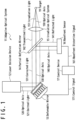
- FIG. 1 is a diagram showing a configuration example of an adaptive optical system 11 according to a related art.
- the adaptive optical system 11 in Fig. 1 is provided with a laser emission device 12, a deformable mirror 13, a partial reflection mirror 14, an irradiation optical system 15, a wavefront sensor 16 and a control device 17.
- a laser beam emitted by the laser emission device 12 will be referred to as emitted light 121 for convenience.
- the emitted light 121 travels along its optical axis 120 and is reflected by the deformable mirror 13 arranged in downstream side of the laser emission device 12.
- the emitted light 121 after being reflected by the deformable mirror 13 will be referred to as corrected light 131 for convenience.
- a part of the corrected light 131 travels along its optical axis 130 and is reflected by the partial reflection mirror 14 arranged in downstream side of the deformable mirror 13. It should be noted that although in the configuration example in Fig. 1 the optical axis 120 and the optical axis 130 are perpendicularly intersecting, this angle may be modified by appropriately adjusting arrangement of the deformable mirror 13. A part of the corrected light 131 that is reflected by the partial reflection mirror 14 will be referred to as reflected light 141 for convenience. The reflected light 141 reaches the wavefront sensor 16. It should be noted that an optical axis 140 of the reflected light 141 is not parallel to the optical axis 130.
- Another part of the corrected light 131 transmits through the partial reflection mirror 14.
- a part of the corrected light 131 that transmitted through the partial reflection mirror 14 will be referred to as transmitted light 142 for convenience.
- the transmitted light 142 travels along the optical axis 130 and transmits through the irradiation optical system 15 arranged in downstream side of the partial reflection mirror 14.
- the transmitted light 142 after transmitting through the irradiation optical system 15 will be referred to as irradiation light 151 for convenience.
- an optical axis 150 of the irradiation light 151 is parallel to the optical axis 130 and the irradiation light 151 focuses at a position of a desired target 19.
- the position of the target 19 is not on the optical axis 130 necessarily.
- the irradiation optical system 15 may appropriately adjust a direction of the optical axis 150 of the irradiation light 151 and the focusing position of the irradiation light 151 based on the position of the target 19.
- the wavefront sensor 16 is electrically connected to the control device 17. More specifically, a wavefront distortion signal 161 generated and outputted by the wavefront sensor 16 is transmitted to the control device 17 and is received by the control device 17.
- the control device 17 is electrically connected to the deformable mirror 13. More specifically, a control signal 171 generated and outputted by the control device 17 is transmitted to the deformable mirror 13 and is received by the deformable mirror 13.
- the deformable mirror 13 returns to an initial state. In other words, the deformable mirror 13 returns its mirror surface to a planar shape. This operation of the deformable mirror 13 may be carried out under control of the control device 17, for example.
- the laser emission device 12 emits the emitted light 121.
- the deformable mirror 13 reflects the emitted light 121 as the corrected light 131 without correcting the wavefront thereof.
- the partial reflection mirror 14 reflects a part of the corrected light 131 as the reflected light 141 and transmits another part of the corrected light 131 as the transmitted light 142.
- the wavefront sensor 16 detects a wavefront distortion of the reflected light 141, generates a wavefront distortion signal 161 that indicates the detected wavefront distortion and transmits it to the control device 17.
- the control device 17 receives the wavefront distortion signal 161 and generates a control signal 171 to correct the wavefront distortion indicated by this wavefront distortion signal 161 by the deformable mirror 13.
- the control device 17 may carry out analysis of the wavefront distortion signal 161 and calculation of the control signal 171 by use of so called Zernike polynomial.
- the control device 17 transmits the generated control signal 171 to the deformable mirror 13.
- the deformable mirror 13 receives the control signal 171 and deforms the mirror surface thereof based on the control signal 171. As a result, the deformable mirror 13 reflects the emitted light 121 that irradiates on the mirror surface thereof and therefore the wavefront of the corrected light 131 that is reflected is corrected. By repeating such feedback control, the wavefront of the corrected light 131 is corrected more accurately and as a result the irradiation light 151 is more accurately focused as well.
- a deformable mirror 13 is provided with a mechanism to deform a mirror surface on back side of the mirror surface. For this reason, it is difficult to add a cooling mechanism on the back side of the mirror surface. Therefore, it is difficult to reflect a high power laser beam by a deformable mirror 13.
- a technology of once diffusing, reflecting by a deformable mirror 13 and then focusing a high power laser beam to suppress generation of heat by a unit area of the deformable mirror 13 is also known. However, in this case, a whole optical system will become larger.
- correction of wavefront will be carried out by use of a transmission type adaptive optical element 3 as described below instead of a deformable mirror 13.
- a wavefront of a laser beam with a higher power will be able to be corrected without enlarging the optical system.
- FIG. 2A is a diagram showing a configuration example of the transmission type adaptive optical system 1 according to an embodiment.
- the transmission type adaptive optical system 1 in Fig. 2A is provided with a laser emission device 2, a transmission type adaptive optical element 3, a partial reflection mirror 4, an irradiation optical system 5, a wavefront sensor 6, a control device 7 and a heating light source 8.
- the laser emission device 2 emits a laser beam as emitted light 21.
- This laser beam is preferably a high power laser beam such as Yb:YAG (Ytterbiumdoped yttrium aluminum garnet) laser beam, Nd:YAG (Neodymium-doped yttrium aluminum garnet) laser beam or the like, for example.
- the transmission type adaptive optical element 3 may be a plate material provided with an appropriate absorption spectrum by doping a glass, a YAG (yttrium aluminum garnet) crystal or the like with ions such as transition metals and rare earths, for example. It is preferable that the transmission type adaptive optical element 3 generated in such a way transmits a laser beam emitted by the laser emission device 2 and that refraction index distribution thereof changes by absorption of heating light 81 irradiated from outside on the other hand. It should be noted that absorption rate of the transmission type adaptive optical element 3 is different based on wavelength of incident light and that the transmission type adaptive optical element 3 preferably transmits light other than the heating light, such as excitation light, guide light or the like, for example.
- the absorption rate of the transmission type adaptive optical element 3 related to absorption of a laser beam emitted by the laser emission device 2, the excitation light, the guide light or the like is smaller than an absorption rate of the transmission type adaptive optical element 3 related to absorption of the heating light.
- the partial reflection mirror 4 reflects a part of incident light as corrected light 31 and transmits another part thereof.
- the irradiation optical system 5 focuses the incident light as transmitted light 42 to a predetermined position.
- the wavefront sensor 6 detects wavefront distortion of the incident light as reflected light 41.
- the control device 7 controls the heating light source 8 based on a detection result of the wavefront sensor 6 and carries out a feedback control of the transmission type adaptive optical system 1.
- the heating light source 8 emits heating light 81 under control of the control device 7 to adjust refraction index distribution of the transmission type adaptive optical element 3.
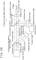
- FIG. 2B is a block circuit diagram showing a configuration example of the control device 7 according to an embodiment.
- the control device 7 in Fig. 2B is provided with a bus 700, an input/output interface 701, a processing device 702, a storage device 703, an external storage device 704 and a recording medium 705.
- control device 7 may be integrated with the wavefront sensor 6 or integrated with the heating light source 8, partially or integrally.
- the description will be carried on given that the wavefront sensor 6, the control device 7 and the heating light source 8 are separately configured and electrically connected.
- the laser beam emitted by the laser emission device 2 will be referred to as emitted light 21 for convenience.
- the emitted light 21 travels along its optical axis 20 and transmits through the transmission type adaptive optical element 3 arranged in downstream side of the laser emission device 2.
- the emitted light 21 after being transmitted through the transmission type adaptive optical element 3 will be referred to as corrected light 31 for convenience.
- a part of the corrected light 31 travels along its optical axis 30 and is reflected by the partial reflection mirror 4 arranged in downstream side of the transmission type adaptive optical element 3.
- the transmission type adaptive optical element 3 is arranged on an optical path between the partial reflection mirror 4 and the laser emission device 2, so as to transmit the emitted light 21.
- the optical axis 20 and the optical axis 30 are parallel.
- a part of the corrected light 31 that is reflected by the partial reflection mirror 4 will be referred to as reflected light 41 for convenience.
- the reflected light 41 reaches the wavefront sensor 6.
- an optical axis 40 of the reflected light 41 is not parallel to the optical axis 20 and the optical axis 30.
- Another part of the corrected light 31 transmits through the partial reflection mirror 4.
- a part of the corrected light 31 that is transmitted through the partial reflection mirror 4 will be referred to as transmitted light 42 for convenience.
- the transmitted light 42 travels along the optical axis 30 and transmits through the irradiation optical system 5 arranged in downstream side of the partial reflection mirror 4.
- the transmitted light 42 after being transmitted through the irradiation optical system 5 will be referred to as irradiation light 51 for convenience.
- an optical axis 50 of the irradiation light 51 is parallel to and identical to the optical axis 20 and the optical axis 30 and the irradiation light 51 focuses at a position of a desired target 9.
- a position of the target 9 is not on the optical axis 20 and the optical axis 30 necessarily.
- the irradiation optical system 5 can appropriately adjust a direction of the optical axis 50 of the irradiation light 51 and the focusing position of the irradiation light 51 based on the position of the target 9 by use of drive system and control system that are not shown.
- the wavefront sensor 6 is electrically connected to the control device 7. More specifically, the wavefront distortion signal 61 generated and outputted by the wavefront sensor 6 is transmitted to the control device 7 and is received by the control device 7.
- the control device 7 is electrically connected to the heating light source 8. More specifically, control signal 71 generated and outputted by the control device 7 is transmitted to the heating light source 8 and is received by the heating light source 8.
- the input/output interface 701, the processing device 702, the storage device 703 and the external storage device 704 are electrically connected to the bus 700 and can communicate to each other via the bus 700.
- the input/output interface 701 is electrically connected to the wavefront sensor 6 and the heating light source 8 in Fig. 2A .
- the external storage device 704 is able to read programs, data and the like from a detachable recording medium 705 and to write thereto on the contrary as well.
- the laser beam emitted by the heating light source 8 will be referred to as heating light 81 for convenience.
- the heating light 81 is emitted along its optical axis 80 to the transmission type adaptive optical element 3. It should be noted that the optical axis 80 is not parallel to the optical axis 20 and the optical axis 30.
- the heating light source 8 returns to an initial state. In other words, the heating light source 8 returns light intensity distribution of the heating light 81 to be emitted in a uniform state. This operation of the heating light source 8 may be carried out under control of the control device 7 for example.
- the transmission type adaptive optical element 3 returns to an initial state in this state, that is, by being irradiated with the heating light 81 having a uniform light intensity distribution. In other words, refraction index distribution of the transmission type adaptive optical element 3 returns to a uniform state.
- the refraction index distribution of the transmission type adaptive optical element 3 in the initial state may not be uniform necessarily. Such a case will be described below. Herein, description will be carried on given that the refractive index distribution of the transmission type adaptive optical element 3 in the initial state is uniform.
- the laser emission device 2 emits the emitted light 21.
- the transmission type adaptive optical element 3 in the initial state transmits the emitted light 21 as corrected light 31 without correcting the wavefront thereof.
- the partial reflection mirror 4 reflects a part of the corrected light 31 as reflected light 41 and transmits another part of the corrected light 31 as transmitted light 42.
- the wavefront sensor 6 detects wavefront distortion of the reflected light 41, generates wavefront distortion signal 61 indicating the detected wavefront distortion and transmits it to the control device 7.
- the control device 7 receives the wavefront distortion signal 61 and generates control signal 71 to correct the wavefront distortion indicated by this wavefront distortion signal 61 by the heating light source 8 and the transmission type adaptive optical element 3.
- the bus 700 mediates communications between the input/output interface 701, the processing device 702, the storage device 703 and the external storage device 704.
- the input/output interface 701 mediates communications between the wavefront sensor 6 and the heating light source 8, that are connected outside the control device 7, and the processing device 702, the storage device 703 and the external storage device 704, that are connected inside the control device 7.
- the processing device 702 reads programs and data stored in the storage device 703, executes the programs and writes results thereof to the storage device 703.
- the storage device 703 stores programs, data and the like.
- the external storage device 704 reads programs, data and the like from the recording medium 705 and write them to the storage device 703, or, on the contrary, reads programs, data and the like from the storage device 703 and writes them to the recording medium 705.
- Fig. 3A is a diagram showing a configuration example of the heating light source 8 according to an embodiment.
- the heating light source 8 in Fig. 3A is provided with a laser emission device 801 and a light intensity distribution adjusting element 802.
- the light intensity distribution adjusting element 802 is arranged in downstream side of the laser beam 82 emitted by the laser emission device 801.
- the light intensity distribution adjusting element 802 is electrically connected to the control device 7.
- the laser emission device 801 in Fig. 3A emits the laser beam 82.
- This laser beam 82 transmits through the light intensity distribution adjusting element 802.
- the laser beam 82 after being transmitted through the light intensity distribution adjusting element 802 is the heating light 81 shown in Fig. 2A .
- the heating light 81 has wavelength absorbed by the transmission type adaptive optical element 3, as described above.
- the transmission type adaptive optical element 3 is heated by absorbing the heating light 81.
- refraction index of the transmission type adaptive optical element 3 is modified. More specifically, when the transmission type adaptive optical element 3 is heated by the heating light 81 having a predetermined light intensity distribution, temperature distribution of the transmission type adaptive optical element 3 will have a distribution similar to the light intensity distribution.
- refraction index of the transmission type adaptive optical element 3 is modified to have a distribution similar to the light intensity distribution.
- the control device 7 can control refraction index distribution of the transmission type adaptive optical element 3 by appropriately adjusting light intensity distribution of the heating light 81.
- Fig. 3B is a diagram showing a configuration example of a light intensity distribution adjusting element 802 according to an embodiment.
- the light intensity distribution adjusting element 802 in Fig. 3B is provided with a plurality of lenses 803 and an actuator 804 that adjusts position of each lens 803.
- the light intensity distribution of the laser beam 82 emitted by the laser emission device 801 is adjusted by transmission of the laser beam 82 through the plurality of lenses 803.
- the actuator 804 moves position of each lens 803 independently, based on control signal 71 generated by the control device 7. For example, the actuator 804 moves lenses 803 in a direction parallel to optical axis 80 of the laser beam 82.
- the actuator 804 may move lenses 803 in a direction perpendicular to the optical axis 80 of the laser beam 82.
- the actuator 804 may incline a lens 803 so that optical axis direction of the lens 803 is not parallel to a direction of the optical axis 80 of the laser beam 82.
- the lens 803 is inclined so that the optical axis direction of the lens 803 intersects or is in a twist position with the optical axis 80 of the laser beam 82.
- the actuator 804 can adjust light intensity distribution of the heating light 81 transmitted through each lens 803 by adjusting position of each lens 803. It should be noted that the lens 803 provided to the light intensity distribution adjusting element 802 may be single.
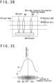
- Fig. 3C is a diagram showing an operation example of a heating light source 8 according to an embodiment.
- An top part in Fig. 3C is a graph G1 showing an example of a distribution of transmittance of the light intensity distribution adjusting element 802 in diameter direction.
- a bottom part in Fig. 3C is a colored map D1 showing in perspective an example of a distribution of transmittance on a surface of the light intensity distribution adjusting element 802.
- a vertical axis an arrow that connects the graph G1 and the colored map D1 shows transmittance.
- the center 810 shows a position where the light intensity distribution adjusting element 802 intersects the optical axis 80.
- a length from the center 810 in a horizontal axis shows a distance from a position where the light intensity distribution adjusting element 802 intersects the optical axis 80.
- the center 810 shows a position where the light intensity distribution adjusting element 802 intersects the optical axis 80, similarly to the graph G1.
- a first area 821, a second area 822 and a third area 823 in the colored map D1 show areas belonging to predetermined ranges of transmittance.
- the first area 821 shows an area with high transmittance.
- the third area 823 shows an area with low transmittance.
- the second area 822 shows an area with transmittance lower than the first area 821 and higher than the third area 823.
- the graph G1 and the colored map D1 show that the light intensity distribution adjusting element 802 has a higher transmittance in an area closer to center part where the optical axis 80 passes and lower transmittance in an area closer to end part away from the optical axis 80 in the contrary.
- Fig. 3C is merely an example and configurations of the transmission type adaptive optical system 1 according to the present embodiment are note limited thereby.
- the heating light 81 that is the laser beam 82 transmitted through the light intensity distribution adjusting element 802 reaches the transmission type adaptive optical element 3 with a higher light intensity in area closer to center part where the optical axis 80 passes.
- the heating light 81 reaches the transmission type adaptive optical element 3 with a lower light intensity in area closer to end part away from the optical axis 80.
- center part of the transmission type adaptive optical element 3 is irradiated with center part of the heating light 81 that has higher light intensity and the temperature thereof becomes higher.
- end part of the transmission type adaptive optical element 3 is irradiated with end part of the heating light 81 that has lower light intensity and the temperature thereof becomes lower compared to the center part of the transmission type adaptive optical element 3.
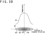
- Fig. 3D is a diagram showing an operation example of a transmission type adaptive optical element 3 according to an embodiment.
- a top part of Fig. 3D is a graph G2 showing an example of temperature distribution in diameter direction of a transmission type adaptive optical element 3.
- a bottom part of Fig. 3D is a colored map D2 showing in perspective an example of temperature distribution of a surface of the transmission type adaptive optical element 3.
- vertical axis (an arrow that connects the graph G2 and the colored map D2) shows temperature.
- a center 310 shows a position where the transmission type adaptive optical element 3 intersects the optical axis 80.
- a length on a horizontal axis from the center 310 shows a distance of the position where the transmission type adaptive optical element 3 intersects the optical axis 80.
- the center 310 shows the position where the transmission type adaptive optical element 3 intersects the optical axis 80, similarly to the graph G2.
- a first area 321, a second area 322 and a third area 323 of the colored map D2 shows areas belonging to predetermined ranges of temperature.
- the first area 321 shows an area with high temperature.
- the third area 323 shows an area with low temperature.
- the second area 322 shows an area with temperature lower than the first area 321 and higher than the third area 323.
- the graph G2 and the colored map D2 show that the temperature of the transmission type adaptive optical element 3 is higher in area closer to center part where the optical axis 30 passes and lower in area closer to end part away from the optical axis 30 in contrary.
- This temperature distribution respectively corresponds to the transmittance distribution shown in Fig. 3C and the light intensity distribution of the heating light 81 emitted to and absorbed by the transmission type adaptive optical element 3 as a result.
- Fig. 3D is, similarly to the case of Fig. 3C , merely an example and that configurations of the transmission type adaptive optical system 1 according to the present embodiment are not limited thereby.
- refraction index related to the emitted light 21 emitted from the laser emission device 2 becomes relatively higher in the center part of the transmission type adaptive optical element 3 where temperature became relatively higher.
- refraction index related to the emitted light 21 becomes relatively lower in an end part of the transmission type adaptive optical element 3 where temperature became relatively lower.
- Wavefront distortion of the emitted light 21 is corrected by such a refractive index distribution.
- temperature distribution of the transmission type adaptive optical element 3 is controlled so that the transmission type adaptive optical element 3 has a refraction index by which wavefront distortion of the emitted light 21 is corrected.
- a configuration example in which the transmission type adaptive optical element 3 has a higher refraction index in a part with higher temperature and a lower refraction index in a part with lower temperature in contrary has been described in the above example.
- the relationship between temperature and refraction index is merely an example and a transmission type adaptive optical element 3 having an opposite relationship, that is, having a lower refraction index in part with higher temperature and a higher refraction index in part with lower temperature may be used.
- the optical axis 80 of the heating light 81 intersects the optical axis 20 of the emitted light 21 and the optical axis 30 of the corrected light 31 at an angle of about 45 degrees.
- This angle is merely an example and configurations of the transmission type adaptive optical system 1 according to the present embodiment are not limited thereby.
- an angle between the optical axis 80 and the optical axis 30 may be perpendicular.
- a practical restriction may arise in a shape of temperature distribution that can be generated in the transmission type adaptive optical element 3. Therefore, the angle between the optical axis 80 and the optical axis 30 is preferably appropriately selected based on temperature distribution that is desired to be generated in the transmission type adaptive optical element 3.
- a variation example of the present embodiment will be described.
- temperature distribution desired to be generated in the transmission type adaptive optical element 3 is known to some extent before the laser emission device 2 emits the laser beam as the emitted light 21.
- This is, for example, a case where there is some trouble in the laser emission device 2 itself and a distortion occurs to wavefront of the emitted light 21 due to this trouble.
- Such kind of wavefront distortion will be referred to as initial distortion for convenience.
- the transmission type adaptive optical element 3 may be able to correct this initial distortion at an initial state thereof. Moreover, the transmission type adaptive optical system 1 may correct, when wavefront distortion is modified based on its own operation time, a fluctuation at that time by feedback control. A correctable range of wavefront distortion by the transmission type adaptive optical element 3 according to the present embodiment can be enlarged efficiently by carrying out such configuration.
- the transmission type adaptive optical element 3 can be considered to make non-uniform a physical shape of the transmission type adaptive optical element 3 in accordance with the initial distortion. Specifically, it can be considered to make non-uniform a thickness of the transmission type adaptive optical element 3 in accordance with the initial distortion. As another example, it can be considered to make non-uniform a dope concentration distribution of absorber included in the transmission type adaptive optical element 3 in accordance with the initial distortion.
- the transmission type adaptive optical system 1 has been described as above. Since the deformable mirror 13 reflects a laser beam, the laser beam needs to be emitted obliquely to a reflection surface of the deformable mirror 13. For this reason, the deformable mirror 13 becomes larger to be applicable to a high power laser beam. On the other hand, since the transmission type adaptive optical element 3 transmits a laser beam, the transmission type adaptive optical element 3 may be irradiated with a laser beam perpendicular to an incident surface thereof. For this reason, the transmission type adaptive optical system 1 according to the present embodiment can be applied to a high power laser beam and correct wavefront distortion thereof without being enlarged compared to the adaptive optical system 11 using a deformable mirror 13 in Fig. 1 .
- FIG. 4 is a diagram showing a configuration example of a transmission type adaptive optical system 1 according to an embodiment forming part of the invention.
- the transmission type adaptive optical system 1 in Fig. 4 is equivalent to the transmission type adaptive optical system 1 in Fig. 2A added with following modifications. That is, the transmission type adaptive optical system 1 as a whole can be downsized of a space between the laser emission device 2 and the transmission type adaptive optical element 3 that is omitted. Furthermore, if optical axes of the laser emission device 2 and the transmission type adaptive optical element 3 are identical, a driving system to adjust position relationship between them can be omitted and the transmission type adaptive optical system 1 can be further downsized.
Description
- The present invention relates to a transmission type adaptive optical system and is suitable for use in a transmission type adaptive optical system that corrects a wavefront of a laser beam for example.
- A wavefront of a laser beam may be disturbed. A wavefront can be defined as a set of points of which optical path length of light emitted from a same light source is same. In case of a laser beam, phase is aligned in a same wavefront. In order to maximize an intensity obtained when focusing a laser beam on an arbitrary point, a phase needs to be aligned at this focusing point. In addition, if a wavefront of a laser beam is disturbed, the laser beam may focus on an undesired point. When an undesired focusing occurs on an optical element through which the laser beam is supposed to pass, this optical element may be damaged. From such a viewpoint or the like, there is a demand to correct wavefront turbulence of laser beam. It should be noted that wavefront turbulence is also called wavefront distortion.
- Wavefront turbulence of laser beam may be caused by, for example, heat occurred in laser medium that generates the laser beam, disturbance in refractive index distribution in an atmosphere where the laser beam propagates, or the like.
- A technology of correcting a wavefront turbulence of a laser beam by a deformable mirror is known. However, deformable mirrors are difficult to cool due to their structure and cannot handle a high power laser beam beyond a certain level.
- In relation with the above, patent literature 1 (
Japanese patent publication 2012-141515 A - In the
patent literature 1, heat distribution is modified by making the fluid optical element to absorb light with a specific wavelength. As a result, refractive index distribution related to light with other wavelength is modified and control of wavefront of this light is carried out by lens effect or the like. However, since the fluid optical element in thepatent literature 1 consists of a liquid, there is a severe limitation in a range of temperature that can be used to control heat distribution. In addition, as convection occurs in a liquid with uneven heat distribution, accuracy in a level of realizing correction of fine wavefront distortion is considered to be difficult to achieve. - [Patent literature 1]
Japanese patent publication 2012-141515 A
US 2016 0104996 A1 discloses a laser sys tem and associated method for controllin g the wave front of a primary laser bea m. The laser system includes a laser med ium for producing a primary laser beam a nd at least one Optical element to which the primary laser beam is directed. The laser system also includes a secondary laser source for producing a secondary l aser beam. The laser system may further include a spatial light modulator config ured to receive the secondary laser beam and to spatially modulate the secondary laser beam having a spatial intensity.
The spatially modulated secondary laser beam may impinge upon at least one of th e laser medium or the at least one optic al element in order to selectively modif y the temperature of portions of the las er medium or the at least one optical el ement upon which the spatially modulated secondary laser beam impinges.
US 2006 0256419 A1 discloses an array fo r modifying a wavefront of an optical be am having a beam axis. Said array compri ses an influencing unit which can be int reduced into the beam path of the optica l beam and a heat source that generates a thermal pattern and acts upon the infl uencing unit. The influencing unit is pr ovided with at least one planar cooling plate that extends transversal to the op tical axis of the incident beam and a fl uid layer or gel layer which has a two-d imensional expansion, is disposed on the cooling plate with a basal surface, and absorbs the heat of the heat source. Th e two-dimensional expansion is large eno ugh to receive approximately the entire cross section of the beam.
The thickness of the fluid layer or gel layer is embodied in such a small manner that only a minute amount of heat can f low perpendicular to the beam axis while being thick enough for the wavefront of the incident beam to be modified by the heat pattern resulting from thermal imp ingement of the fluid or gel. The wavefr ont of a beam can thus be influenced in an inexpensive-and tailor-made manner. B eams that are influenced in such a way c an preferably be used in high-power lase rs for creating custom modes.
EDUARD WYSS ET AL: "Thermooptical Compen sation Methods for High-Power Lasers", I EEE JOURNAL OF QUANTUM ELECTRONICS, IEEE SERVICECENTER, PISCATAWAY, NJ, USA, vo l. 38, no. 12, 1 December 2002 (2002-12-01), XP011065324 discloses that thermall y induced optical effects can be exploit ed to generate adaptive optical devices such as self-adjusting lenses. An adapt! ve lens in a resonator can be used to co mpensate for the thermal lens in a high-power solid-state laser rod LR and herew ith significantly improve the beam qualit y and increase the output-power range of solid-state lasers.
With suitable materials and an appropria te design of the compensating device, re sonators with self-balancing thermal len ses can be developed.
US 2010 201958 A1 discloses an optical c orrection device with thermal actuators for influencing the temperature distribu tion in the optical correction device. T he optical correction device is construc ted from at least two partial elements w hich differ with regard to their ability to transport heat. - An object of the present inventi on is to provide a transmission type ada ptive optical system that can be applied to a high power laser beam beyond a lim it of deformable mirrors and corrects wa vefront turbulence of a laser beam with adaptation to the wavefront turbulence. Other objects and new features will be understood from description of the prese nt description and attached drawings.
- The above object is achieved by a transmission type adaptive optical system according to
claim 1. The dependent claims are directed to different advantageous aspects of the invention.
Especially the system of the invention is provided with a laser emission device, a partial reflection mirror, a wavefront sensor, a control device, a heating light source, a transmission type adaptive optical element and an irradiation optical system. Herein, the laser emission device emits a laser beam. The partial reflection mirror reflects a part of the laser beam as reflected light and transmits another part as transmission light. The wavefront sensor detects wavefront distortion of the reflected light, generates wavefront distortion signal indicating the wavefront distortion and outputs it. The control device generates control signal to correct the wavefront distortion based on the wavefront distortion signal and outputs it. The heating light source generates heating light that adjusts temperature distribution in an irradiated optical element based on the control signal and emits it. The transmission type adaptive optical element is arranged on a light path between the laser emission device and the partial reflection mirror to transmit the laser beam and configured to correct the wavefront of the laser beam by a refraction index distribution adjusted by a temperature distribution occurred by irradiation of the heating light. The irradiation optical system irradiates a desired target with transmission light that is transmitted through the partial reflection mirror. - By using a transmission type adaptive optical element of which refractive index distribution changes based on temperature distribution thereof, a wavefront turbulence of a high power laser beam can be corrected with adaptation to this wavefront turbulence.
The above object is achieved by means of the transmission type adaptive optical system according to the independent claims. The dependent claims are directed to different advantageous aspects of the invention. - According to the above described embodiment, by using a transmission type adaptive optical element of which refractive index distribution changes based on temperature distribution thereof, a wavefront turbulence of a high power laser beam can be corrected with adaptation to this wavefront turbulence.
-
- [
Fig. 1] Fig. 1 is a diagram showing a configuration example of an adaptive optical system related to a related art. - [
Fig. 2A] Fig. 2A is a diagram showing a configuration example of a transmission type adaptive optical system according to an embodiment. - [
Fig. 2B] Fig. 2B is a diagram showing a configuration example of a control device according to an embodiment. - [
Fig. 3A] Fig. 3A is a diagram showing a configuration example of a heating light source according to an embodiment. - [
Fig. 3B] Fig. 3B is a diagram showing a configuration example of a light intensity distribution adjusting element according to an embodiment. - [
Fig. 3C] Fig. 3C is a diagram showing an operation example of the heating light source according to an embodiment. - [
Fig. 3D] Fig. 3D is a diagram showing an operation example of the transmission type adaptive optical element according to an embodiment. - [
Fig. 4] Fig. 4 is a diagram showing a configuration example of the transmission type adaptive optical system according to an embodiment. - An embodiment of a transmission type adaptive optical system according to the present invention will be described below with reference to attached drawings.
- For a better understanding of the transmission type adaptive optical system according to the present invention, an adaptive
optical system 11 according to a related art will be described at first with reference toFig. 1. Fig. 1 is a diagram showing a configuration example of an adaptiveoptical system 11 according to a related art. - Components of the adaptive
optical system 11 inFig. 1 will be described. The adaptiveoptical system 11 inFig. 1 is provided with alaser emission device 12, adeformable mirror 13, apartial reflection mirror 14, an irradiationoptical system 15, awavefront sensor 16 and acontrol device 17. - Connection relationship and arrangement relationship of the components of the adaptive
optical system 11 inFig. 1 will be described. A laser beam emitted by thelaser emission device 12 will be referred to as emitted light 121 for convenience. The emitted light 121 travels along itsoptical axis 120 and is reflected by thedeformable mirror 13 arranged in downstream side of thelaser emission device 12. The emitted light 121 after being reflected by thedeformable mirror 13 will be referred to as correctedlight 131 for convenience. - A part of the corrected light 131 travels along its
optical axis 130 and is reflected by thepartial reflection mirror 14 arranged in downstream side of thedeformable mirror 13. It should be noted that although in the configuration example inFig. 1 theoptical axis 120 and theoptical axis 130 are perpendicularly intersecting, this angle may be modified by appropriately adjusting arrangement of thedeformable mirror 13. A part of the corrected light 131 that is reflected by thepartial reflection mirror 14 will be referred to as reflected light 141 for convenience. The reflectedlight 141 reaches thewavefront sensor 16. It should be noted that anoptical axis 140 of the reflectedlight 141 is not parallel to theoptical axis 130. - Another part of the corrected light 131 transmits through the
partial reflection mirror 14. A part of the corrected light 131 that transmitted through thepartial reflection mirror 14 will be referred to as transmitted light 142 for convenience. The transmitted light 142 travels along theoptical axis 130 and transmits through the irradiationoptical system 15 arranged in downstream side of thepartial reflection mirror 14. The transmitted light 142 after transmitting through the irradiationoptical system 15 will be referred to asirradiation light 151 for convenience. - It should be noted that in the configuration example in
Fig. 1 anoptical axis 150 of theirradiation light 151 is parallel to theoptical axis 130 and theirradiation light 151 focuses at a position of a desiredtarget 19. However, this is merely an example. Specifically, the position of thetarget 19 is not on theoptical axis 130 necessarily. On the contrary, the irradiationoptical system 15 may appropriately adjust a direction of theoptical axis 150 of theirradiation light 151 and the focusing position of theirradiation light 151 based on the position of thetarget 19. - The
wavefront sensor 16 is electrically connected to thecontrol device 17. More specifically, awavefront distortion signal 161 generated and outputted by thewavefront sensor 16 is transmitted to thecontrol device 17 and is received by thecontrol device 17. Thecontrol device 17 is electrically connected to thedeformable mirror 13. More specifically, acontrol signal 171 generated and outputted by thecontrol device 17 is transmitted to thedeformable mirror 13 and is received by thedeformable mirror 13. - Operations of components of the adaptive
optical system 11 inFig. 1 will be described. At first, thedeformable mirror 13 returns to an initial state. In other words, thedeformable mirror 13 returns its mirror surface to a planar shape. This operation of thedeformable mirror 13 may be carried out under control of thecontrol device 17, for example. In this state, thelaser emission device 12 emits the emittedlight 121. Thedeformable mirror 13 reflects the emitted light 121 as the correctedlight 131 without correcting the wavefront thereof. Thepartial reflection mirror 14 reflects a part of the corrected light 131 as the reflectedlight 141 and transmits another part of the corrected light 131 as the transmittedlight 142. Thewavefront sensor 16 detects a wavefront distortion of the reflectedlight 141, generates awavefront distortion signal 161 that indicates the detected wavefront distortion and transmits it to thecontrol device 17. Thecontrol device 17 receives thewavefront distortion signal 161 and generates acontrol signal 171 to correct the wavefront distortion indicated by thiswavefront distortion signal 161 by thedeformable mirror 13. Herein, thecontrol device 17 may carry out analysis of thewavefront distortion signal 161 and calculation of thecontrol signal 171 by use of so called Zernike polynomial. Thecontrol device 17 transmits the generatedcontrol signal 171 to thedeformable mirror 13. - The
deformable mirror 13 receives thecontrol signal 171 and deforms the mirror surface thereof based on thecontrol signal 171. As a result, thedeformable mirror 13 reflects the emitted light 121 that irradiates on the mirror surface thereof and therefore the wavefront of the corrected light 131 that is reflected is corrected. By repeating such feedback control, the wavefront of the correctedlight 131 is corrected more accurately and as a result theirradiation light 151 is more accurately focused as well. - However, the technology of correcting a wavefront of a laser beam by use of a
deformable mirror 13 has limitations as follows. That is, adeformable mirror 13 is provided with a mechanism to deform a mirror surface on back side of the mirror surface. For this reason, it is difficult to add a cooling mechanism on the back side of the mirror surface. Therefore, it is difficult to reflect a high power laser beam by adeformable mirror 13. It should be noted that a technology of once diffusing, reflecting by adeformable mirror 13 and then focusing a high power laser beam to suppress generation of heat by a unit area of thedeformable mirror 13 is also known. However, in this case, a whole optical system will become larger. - Thus, in the present embodiment, correction of wavefront will be carried out by use of a transmission type adaptive
optical element 3 as described below instead of adeformable mirror 13. As a result, a wavefront of a laser beam with a higher power will be able to be corrected without enlarging the optical system. - A transmission type adaptive
optical system 1 according to the present embodiment will be described with reference toFig. 2A. Fig. 2A is a diagram showing a configuration example of the transmission type adaptiveoptical system 1 according to an embodiment. - Components of the transmission type adaptive
optical system 1 inFig. 2A will be described. The transmission type adaptiveoptical system 1 inFig. 2A is provided with alaser emission device 2, a transmission type adaptiveoptical element 3, apartial reflection mirror 4, an irradiationoptical system 5, awavefront sensor 6, acontrol device 7 and aheating light source 8. - The
laser emission device 2 emits a laser beam as emittedlight 21. This laser beam is preferably a high power laser beam such as Yb:YAG (Ytterbiumdoped yttrium aluminum garnet) laser beam, Nd:YAG (Neodymium-doped yttrium aluminum garnet) laser beam or the like, for example. - The transmission type adaptive
optical element 3 may be a plate material provided with an appropriate absorption spectrum by doping a glass, a YAG (yttrium aluminum garnet) crystal or the like with ions such as transition metals and rare earths, for example. It is preferable that the transmission type adaptiveoptical element 3 generated in such a way transmits a laser beam emitted by thelaser emission device 2 and that refraction index distribution thereof changes by absorption ofheating light 81 irradiated from outside on the other hand. It should be noted that absorption rate of the transmission type adaptiveoptical element 3 is different based on wavelength of incident light and that the transmission type adaptiveoptical element 3 preferably transmits light other than the heating light, such as excitation light, guide light or the like, for example. In other words, the absorption rate of the transmission type adaptiveoptical element 3 related to absorption of a laser beam emitted by thelaser emission device 2, the excitation light, the guide light or the like is smaller than an absorption rate of the transmission type adaptiveoptical element 3 related to absorption of the heating light. - The
partial reflection mirror 4 reflects a part of incident light as correctedlight 31 and transmits another part thereof. The irradiationoptical system 5 focuses the incident light as transmitted light 42 to a predetermined position. Thewavefront sensor 6 detects wavefront distortion of the incident light as reflectedlight 41. Thecontrol device 7 controls theheating light source 8 based on a detection result of thewavefront sensor 6 and carries out a feedback control of the transmission type adaptiveoptical system 1. Theheating light source 8 emitsheating light 81 under control of thecontrol device 7 to adjust refraction index distribution of the transmission type adaptiveoptical element 3. - A configuration example of the
control device 7 according to the present embodiment will be described with reference toFig. 2B. Fig. 2B is a block circuit diagram showing a configuration example of thecontrol device 7 according to an embodiment. - Components of the
control device 7 inFig. 2B will be described. Thecontrol device 7 inFig. 2B is provided with a bus 700, an input/output interface 701, aprocessing device 702, astorage device 703, anexternal storage device 704 and arecording medium 705. - It should be noted that the
control device 7 may be integrated with thewavefront sensor 6 or integrated with theheating light source 8, partially or integrally. Herein, the description will be carried on given that thewavefront sensor 6, thecontrol device 7 and theheating light source 8 are separately configured and electrically connected. - Connection relationship and arrangement relationship of components of the transmission type adaptive
optical system 1 inFig. 2A will be described. The laser beam emitted by thelaser emission device 2 will be referred to as emitted light 21 for convenience. The emitted light 21 travels along itsoptical axis 20 and transmits through the transmission type adaptiveoptical element 3 arranged in downstream side of thelaser emission device 2. The emitted light 21 after being transmitted through the transmission type adaptiveoptical element 3 will be referred to as correctedlight 31 for convenience. - A part of the corrected light 31 travels along its
optical axis 30 and is reflected by thepartial reflection mirror 4 arranged in downstream side of the transmission type adaptiveoptical element 3. In other words, the transmission type adaptiveoptical element 3 is arranged on an optical path between thepartial reflection mirror 4 and thelaser emission device 2, so as to transmit the emittedlight 21. It should be noted that in the configuration example inFig. 2A theoptical axis 20 and theoptical axis 30 are parallel. A part of the corrected light 31 that is reflected by thepartial reflection mirror 4 will be referred to as reflectedlight 41 for convenience. The reflectedlight 41 reaches thewavefront sensor 6. It should be noted that anoptical axis 40 of the reflectedlight 41 is not parallel to theoptical axis 20 and theoptical axis 30. - Another part of the corrected light 31 transmits through the
partial reflection mirror 4. A part of the corrected light 31 that is transmitted through thepartial reflection mirror 4 will be referred to as transmittedlight 42 for convenience. The transmitted light 42 travels along theoptical axis 30 and transmits through the irradiationoptical system 5 arranged in downstream side of thepartial reflection mirror 4. The transmitted light 42 after being transmitted through the irradiationoptical system 5 will be referred to asirradiation light 51 for convenience. - It should be noted that in the configuration example in
Fig. 2A anoptical axis 50 of theirradiation light 51 is parallel to and identical to theoptical axis 20 and theoptical axis 30 and theirradiation light 51 focuses at a position of a desiredtarget 9. However, this is merely an example and configurations of the transmission type adaptiveoptical system 1 according to the present embodiment are not limited thereby. Specifically, a position of thetarget 9 is not on theoptical axis 20 and theoptical axis 30 necessarily. On the contrary, it is preferable that the irradiationoptical system 5 can appropriately adjust a direction of theoptical axis 50 of theirradiation light 51 and the focusing position of theirradiation light 51 based on the position of thetarget 9 by use of drive system and control system that are not shown. - The
wavefront sensor 6 is electrically connected to thecontrol device 7. More specifically, thewavefront distortion signal 61 generated and outputted by thewavefront sensor 6 is transmitted to thecontrol device 7 and is received by thecontrol device 7. Thecontrol device 7 is electrically connected to theheating light source 8. More specifically,control signal 71 generated and outputted by thecontrol device 7 is transmitted to theheating light source 8 and is received by theheating light source 8. - Connection relationship of components of the
control device 7 inFig. 2B will be described. The input/output interface 701, theprocessing device 702, thestorage device 703 and theexternal storage device 704 are electrically connected to the bus 700 and can communicate to each other via the bus 700. The input/output interface 701 is electrically connected to thewavefront sensor 6 and theheating light source 8 inFig. 2A . Theexternal storage device 704 is able to read programs, data and the like from adetachable recording medium 705 and to write thereto on the contrary as well. - The laser beam emitted by the
heating light source 8 will be referred to asheating light 81 for convenience. Theheating light 81 is emitted along itsoptical axis 80 to the transmission type adaptiveoptical element 3. It should be noted that theoptical axis 80 is not parallel to theoptical axis 20 and theoptical axis 30. - Operations of components of the transmission type adaptive
optical system 1 inFig. 2A will be described. At first, theheating light source 8 returns to an initial state. In other words, theheating light source 8 returns light intensity distribution of theheating light 81 to be emitted in a uniform state. This operation of theheating light source 8 may be carried out under control of thecontrol device 7 for example. The transmission type adaptiveoptical element 3 returns to an initial state in this state, that is, by being irradiated with theheating light 81 having a uniform light intensity distribution. In other words, refraction index distribution of the transmission type adaptiveoptical element 3 returns to a uniform state. - It should be noted that the refraction index distribution of the transmission type adaptive
optical element 3 in the initial state may not be uniform necessarily. Such a case will be described below. Herein, description will be carried on given that the refractive index distribution of the transmission type adaptiveoptical element 3 in the initial state is uniform. - In a state where the
heating light source 8 and the transmission type adaptiveoptical element 3 are returned to the initial states, thelaser emission device 2 emits the emittedlight 21. The transmission type adaptiveoptical element 3 in the initial state transmits the emitted light 21 as correctedlight 31 without correcting the wavefront thereof. Thepartial reflection mirror 4 reflects a part of the corrected light 31 as reflected light 41 and transmits another part of the corrected light 31 as transmittedlight 42. Thewavefront sensor 6 detects wavefront distortion of the reflectedlight 41, generateswavefront distortion signal 61 indicating the detected wavefront distortion and transmits it to thecontrol device 7. Thecontrol device 7 receives thewavefront distortion signal 61 and generatescontrol signal 71 to correct the wavefront distortion indicated by thiswavefront distortion signal 61 by theheating light source 8 and the transmission type adaptiveoptical element 3. - Operations of components of the
control device 7 inFig. 2B will be described. The bus 700 mediates communications between the input/output interface 701, theprocessing device 702, thestorage device 703 and theexternal storage device 704. The input/output interface 701 mediates communications between thewavefront sensor 6 and theheating light source 8, that are connected outside thecontrol device 7, and theprocessing device 702, thestorage device 703 and theexternal storage device 704, that are connected inside thecontrol device 7. Theprocessing device 702 reads programs and data stored in thestorage device 703, executes the programs and writes results thereof to thestorage device 703. Thestorage device 703 stores programs, data and the like. Theexternal storage device 704 reads programs, data and the like from therecording medium 705 and write them to thestorage device 703, or, on the contrary, reads programs, data and the like from thestorage device 703 and writes them to therecording medium 705. - It will be described that wavefront distortion of the emitted light 21 can be corrected by use of the
heating light source 8 and the transmission type adaptiveoptical element 3, with reference toFigs. 3A to 3D .Fig. 3A is a diagram showing a configuration example of theheating light source 8 according to an embodiment. - The
heating light source 8 inFig. 3A is provided with alaser emission device 801 and a light intensity distribution adjusting element 802. The light intensity distribution adjusting element 802 is arranged in downstream side of thelaser beam 82 emitted by thelaser emission device 801. In addition, the light intensity distribution adjusting element 802 is electrically connected to thecontrol device 7. - The
laser emission device 801 inFig. 3A emits thelaser beam 82. Thislaser beam 82 transmits through the light intensity distribution adjusting element 802. Thelaser beam 82 after being transmitted through the light intensity distribution adjusting element 802 is theheating light 81 shown inFig. 2A . Theheating light 81 has wavelength absorbed by the transmission type adaptiveoptical element 3, as described above. The transmission type adaptiveoptical element 3 is heated by absorbing theheating light 81. When an absorption body included in the transmission type adaptiveoptical element 3 is heated, refraction index of the transmission type adaptiveoptical element 3 is modified. More specifically, when the transmission type adaptiveoptical element 3 is heated by theheating light 81 having a predetermined light intensity distribution, temperature distribution of the transmission type adaptiveoptical element 3 will have a distribution similar to the light intensity distribution. As a result, refraction index of the transmission type adaptiveoptical element 3 is modified to have a distribution similar to the light intensity distribution. In other words, thecontrol device 7 can control refraction index distribution of the transmission type adaptiveoptical element 3 by appropriately adjusting light intensity distribution of theheating light 81. -
Fig. 3B is a diagram showing a configuration example of a light intensity distribution adjusting element 802 according to an embodiment. The light intensity distribution adjusting element 802 inFig. 3B is provided with a plurality oflenses 803 and anactuator 804 that adjusts position of eachlens 803. The light intensity distribution of thelaser beam 82 emitted by thelaser emission device 801 is adjusted by transmission of thelaser beam 82 through the plurality oflenses 803. Theactuator 804 moves position of eachlens 803 independently, based oncontrol signal 71 generated by thecontrol device 7. For example, theactuator 804moves lenses 803 in a direction parallel tooptical axis 80 of thelaser beam 82. In addition, theactuator 804 may movelenses 803 in a direction perpendicular to theoptical axis 80 of thelaser beam 82. In addition, theactuator 804 may incline alens 803 so that optical axis direction of thelens 803 is not parallel to a direction of theoptical axis 80 of thelaser beam 82. In other words, thelens 803 is inclined so that the optical axis direction of thelens 803 intersects or is in a twist position with theoptical axis 80 of thelaser beam 82. Theactuator 804 can adjust light intensity distribution of theheating light 81 transmitted through eachlens 803 by adjusting position of eachlens 803. It should be noted that thelens 803 provided to the light intensity distribution adjusting element 802 may be single. -
Fig. 3C is a diagram showing an operation example of aheating light source 8 according to an embodiment. An top part inFig. 3C is a graph G1 showing an example of a distribution of transmittance of the light intensity distribution adjusting element 802 in diameter direction. In addition, a bottom part inFig. 3C is a colored map D1 showing in perspective an example of a distribution of transmittance on a surface of the light intensity distribution adjusting element 802. In the graph G1, a vertical axis (an arrow that connects the graph G1 and the colored map D1) shows transmittance. Thecenter 810 shows a position where the light intensity distribution adjusting element 802 intersects theoptical axis 80. A length from thecenter 810 in a horizontal axis shows a distance from a position where the light intensity distribution adjusting element 802 intersects theoptical axis 80. In the colored map D1, thecenter 810 shows a position where the light intensity distribution adjusting element 802 intersects theoptical axis 80, similarly to the graph G1. In addition, afirst area 821, asecond area 822 and athird area 823 in the colored map D1 show areas belonging to predetermined ranges of transmittance. Thefirst area 821 shows an area with high transmittance. Thethird area 823 shows an area with low transmittance. Thesecond area 822 shows an area with transmittance lower than thefirst area 821 and higher than thethird area 823. - In the example of
Fig. 3C , the graph G1 and the colored map D1 show that the light intensity distribution adjusting element 802 has a higher transmittance in an area closer to center part where theoptical axis 80 passes and lower transmittance in an area closer to end part away from theoptical axis 80 in the contrary. It should be noted thatFig. 3C is merely an example and configurations of the transmission type adaptiveoptical system 1 according to the present embodiment are note limited thereby. - In case of
Fig. 3C , theheating light 81 that is thelaser beam 82 transmitted through the light intensity distribution adjusting element 802 reaches the transmission type adaptiveoptical element 3 with a higher light intensity in area closer to center part where theoptical axis 80 passes. In addition, on the other hand, theheating light 81 reaches the transmission type adaptiveoptical element 3 with a lower light intensity in area closer to end part away from theoptical axis 80. As a result, center part of the transmission type adaptiveoptical element 3 is irradiated with center part of theheating light 81 that has higher light intensity and the temperature thereof becomes higher. In addition, end part of the transmission type adaptiveoptical element 3 is irradiated with end part of theheating light 81 that has lower light intensity and the temperature thereof becomes lower compared to the center part of the transmission type adaptiveoptical element 3. -
Fig. 3D is a diagram showing an operation example of a transmission type adaptiveoptical element 3 according to an embodiment. A top part ofFig. 3D is a graph G2 showing an example of temperature distribution in diameter direction of a transmission type adaptiveoptical element 3. In addition, a bottom part ofFig. 3D is a colored map D2 showing in perspective an example of temperature distribution of a surface of the transmission type adaptiveoptical element 3. In the graph G2, vertical axis (an arrow that connects the graph G2 and the colored map D2) shows temperature. Acenter 310 shows a position where the transmission type adaptiveoptical element 3 intersects theoptical axis 80. A length on a horizontal axis from thecenter 310 shows a distance of the position where the transmission type adaptiveoptical element 3 intersects theoptical axis 80. In the colored map D2, thecenter 310 shows the position where the transmission type adaptiveoptical element 3 intersects theoptical axis 80, similarly to the graph G2. In addition, afirst area 321, asecond area 322 and athird area 323 of the colored map D2 shows areas belonging to predetermined ranges of temperature. Thefirst area 321 shows an area with high temperature. Thethird area 323 shows an area with low temperature. Thesecond area 322 shows an area with temperature lower than thefirst area 321 and higher than thethird area 323. - In the example of
Fig. 3D , the graph G2 and the colored map D2 show that the temperature of the transmission type adaptiveoptical element 3 is higher in area closer to center part where theoptical axis 30 passes and lower in area closer to end part away from theoptical axis 30 in contrary. This temperature distribution respectively corresponds to the transmittance distribution shown inFig. 3C and the light intensity distribution of theheating light 81 emitted to and absorbed by the transmission type adaptiveoptical element 3 as a result. It should be noted thatFig. 3D is, similarly to the case ofFig. 3C , merely an example and that configurations of the transmission type adaptiveoptical system 1 according to the present embodiment are not limited thereby. - In case of
Fig. 3D , refraction index related to the emitted light 21 emitted from thelaser emission device 2 becomes relatively higher in the center part of the transmission type adaptiveoptical element 3 where temperature became relatively higher. In addition, on the other hand, refraction index related to the emittedlight 21 becomes relatively lower in an end part of the transmission type adaptiveoptical element 3 where temperature became relatively lower. Wavefront distortion of the emittedlight 21 is corrected by such a refractive index distribution. In other words, temperature distribution of the transmission type adaptiveoptical element 3 is controlled so that the transmission type adaptiveoptical element 3 has a refraction index by which wavefront distortion of the emittedlight 21 is corrected. - A configuration example in which the transmission type adaptive
optical element 3 has a higher refraction index in a part with higher temperature and a lower refraction index in a part with lower temperature in contrary has been described in the above example. The relationship between temperature and refraction index is merely an example and a transmission type adaptiveoptical element 3 having an opposite relationship, that is, having a lower refraction index in part with higher temperature and a higher refraction index in part with lower temperature may be used. - In the configuration example in
Fig. 2A , theoptical axis 80 of theheating light 81 intersects theoptical axis 20 of the emittedlight 21 and theoptical axis 30 of the corrected light 31 at an angle of about 45 degrees. This angle is merely an example and configurations of the transmission type adaptiveoptical system 1 according to the present embodiment are not limited thereby. For example, an angle between theoptical axis 80 and theoptical axis 30 may be perpendicular. However, in such a case, a practical restriction may arise in a shape of temperature distribution that can be generated in the transmission type adaptiveoptical element 3. Therefore, the angle between theoptical axis 80 and theoptical axis 30 is preferably appropriately selected based on temperature distribution that is desired to be generated in the transmission type adaptiveoptical element 3. - A variation example of the present embodiment will be described. There is a case where temperature distribution desired to be generated in the transmission type adaptive
optical element 3 is known to some extent before thelaser emission device 2 emits the laser beam as the emittedlight 21. This is, for example, a case where there is some trouble in thelaser emission device 2 itself and a distortion occurs to wavefront of the emittedlight 21 due to this trouble. Such kind of wavefront distortion will be referred to as initial distortion for convenience. - If an initial distortion is known, the transmission type adaptive
optical element 3 may be able to correct this initial distortion at an initial state thereof. Moreover, the transmission type adaptiveoptical system 1 may correct, when wavefront distortion is modified based on its own operation time, a fluctuation at that time by feedback control. A correctable range of wavefront distortion by the transmission type adaptiveoptical element 3 according to the present embodiment can be enlarged efficiently by carrying out such configuration. - As a configuration able to correct initial distortion, for example, it can be considered to make non-uniform a physical shape of the transmission type adaptive
optical element 3 in accordance with the initial distortion. Specifically, it can be considered to make non-uniform a thickness of the transmission type adaptiveoptical element 3 in accordance with the initial distortion. As another example, it can be considered to make non-uniform a dope concentration distribution of absorber included in the transmission type adaptiveoptical element 3 in accordance with the initial distortion. - The transmission type adaptive
optical system 1 according to an embodiment has been described as above. Since thedeformable mirror 13 reflects a laser beam, the laser beam needs to be emitted obliquely to a reflection surface of thedeformable mirror 13. For this reason, thedeformable mirror 13 becomes larger to be applicable to a high power laser beam. On the other hand, since the transmission type adaptiveoptical element 3 transmits a laser beam, the transmission type adaptiveoptical element 3 may be irradiated with a laser beam perpendicular to an incident surface thereof. For this reason, the transmission type adaptiveoptical system 1 according to the present embodiment can be applied to a high power laser beam and correct wavefront distortion thereof without being enlarged compared to the adaptiveoptical system 11 using adeformable mirror 13 inFig. 1 . - A transmission type adaptive
optical system 1 according to the present embodiment that forms part of the invention will be described with reference toFig. 4. Fig. 4 is a diagram showing a configuration example of a transmission type adaptiveoptical system 1 according to an embodiment forming part of the invention. - The transmission type adaptive
optical system 1 inFig. 4 is equivalent to the transmission type adaptiveoptical system 1 inFig. 2A added with following modifications. That is, the transmission type adaptiveoptical system 1 as a whole can be downsized of a space between thelaser emission device 2 and the transmission type adaptiveoptical element 3 that is omitted. Furthermore, if optical axes of thelaser emission device 2 and the transmission type adaptiveoptical element 3 are identical, a driving system to adjust position relationship between them can be omitted and the transmission type adaptiveoptical system 1 can be further downsized. - Other configuration of the transmission type adaptive
optical system 1 inFig. 4 is similar to the case inFig. 2A and therefore further detailed description thereof will be omitted.
Claims (5)
- A transmission type adaptive optical system comprising:a laser emission device (2) configured to emit a laser beam;a partial reflection mirror (4) configured to reflect a part of the laser beam as reflected light and transmit another part thereof as transmission light;a wavefront sensor (6) configured to detect wavefront distortion of the reflected light and to generate and output a wavefront distortion signal indicating the wavefront distortion;a control device (7) configured to generate and output a control signal to correct the wavefront distortion based on the wavefront distortion signal;a heating light source (8) configured to generate and emit heating light that adjusts temperature distribution in an irradiated optical element based on the control signal;a transmission type adaptive optical element (3) arranged on a light path between the laser emission device (2) and the partial reflection mirror (4) to transmit the laser beam and configured to correct a wavefront of the laser beam by a refraction index distribution adjusted by a temperature distribution occurred by irradiation of the heating light; andan irradiation optical system (5) configured to irradiate a desired target with transmission light that is transmitted through the partial reflection mirror;wherein the heating light is an other laser beam having a wavelength different from the laser beam,wherein a first absorption rate of absorbing the laser beam by the transmission type adaptive optical element (3) is smaller than a second absorption rate of absorbing the other laser beam by the transmission type adaptive optical element (3); andcharacterised in that the transmission type adaptive optical element (3) is fixed to the laser emission device (2).
- The transmission type adaptive optical system according to claim 1,
wherein the heating light source (8) comprises:another laser emission device (801) configured to emit the other laser beam; anda light intensity distribution adjusting element (802) configured to adjust a light intensity distribution of the other laser beam based on the control signal so as to generate the refraction index distribution in the transmission type adaptive optical element as desired. - The transmission type adaptive optical system according to any one of claims 1 or 2,
wherein the transmission type adaptive optical element (3) has a non-uniform refraction index distribution in an initial state. - The transmission type adaptive optical system according to claim 3,
wherein the transmission type adaptive optical element (3) comprises an absorption body having a non-uniform dope concentration distribution. - The transmission type adaptive optical system according to claim 3 or 4,
wherein the transmission type adaptive optical element (3) has a non-uniform thickness.
Applications Claiming Priority (2)
| Application Number | Priority Date | Filing Date | Title |
|---|---|---|---|
| JP2018032277 | 2018-02-26 | ||
| PCT/JP2019/003607 WO2019163481A1 (en) | 2018-02-26 | 2019-02-01 | Transmission adaptive optical system |
Publications (3)
| Publication Number | Publication Date |
|---|---|
| EP3657237A1 EP3657237A1 (en) | 2020-05-27 |
| EP3657237A4 EP3657237A4 (en) | 2020-11-11 |
| EP3657237B1 true EP3657237B1 (en) | 2023-12-13 |
Family
ID=67687202
Family Applications (1)
| Application Number | Title | Priority Date | Filing Date |
|---|---|---|---|
| EP19757140.9A Active EP3657237B1 (en) | 2018-02-26 | 2019-02-01 | Transmission adaptive optical system |
Country Status (4)
| Country | Link |
|---|---|
| US (1) | US11520173B2 (en) |
| EP (1) | EP3657237B1 (en) |
| JP (1) | JP6874205B2 (en) |
| WO (1) | WO2019163481A1 (en) |
Families Citing this family (3)
| Publication number | Priority date | Publication date | Assignee | Title |
|---|---|---|---|---|
| US20210286227A1 (en) * | 2020-03-11 | 2021-09-16 | Saudi Arabian Oil Company | Reconfigurable optics for beam transformation |
| CN112710404B (en) * | 2020-12-17 | 2022-04-08 | 电子科技大学 | Optical device surface temperature distribution detection method based on compressed sensing |
| CN113310902B (en) * | 2021-05-26 | 2023-10-03 | 中国科学院光电技术研究所 | Cavity ring-down self-adaptive optical active transverse mode matching method |
Citations (1)
| Publication number | Priority date | Publication date | Assignee | Title |
|---|---|---|---|---|
| US20160104996A1 (en) * | 2014-10-10 | 2016-04-14 | The Boeing Company | Laser system and method for controlling the wave front of a laser beam |
Family Cites Families (10)
| Publication number | Priority date | Publication date | Assignee | Title |
|---|---|---|---|---|
| JPH03149524A (en) * | 1989-11-07 | 1991-06-26 | Sharp Corp | Spatial modulator |
| US6028977A (en) * | 1995-11-13 | 2000-02-22 | Moriah Technologies, Inc. | All-optical, flat-panel display system |
| TW200414280A (en) | 2002-09-25 | 2004-08-01 | Adv Lcd Tech Dev Ct Co Ltd | Semiconductor device, annealing method, annealing apparatus and display apparatus |
| EP1599757B1 (en) * | 2003-02-26 | 2007-05-30 | Universität Bern | Method and device to modify a wavefront of an optical beam |
| JP2004336013A (en) * | 2003-04-15 | 2004-11-25 | Advanced Lcd Technologies Development Center Co Ltd | Annealing method, annealing apparatus, and display |
| US8731013B2 (en) * | 2007-01-24 | 2014-05-20 | Raytheon Company | Linear adaptive optics system in low power beam path and method |
| EP2181357A1 (en) * | 2007-08-24 | 2010-05-05 | Carl Zeiss SMT AG | Controllable optical element and method for operating an optical element with thermal actuators and projection exposure apparatus for semiconductor lithography |
| US8198564B2 (en) | 2008-09-09 | 2012-06-12 | Electro Scientific Industries, Inc. | Adaptive optic beamshaping in laser processing systems |
| JP2012141515A (en) | 2011-01-05 | 2012-07-26 | Tokyo Institute Of Technology | Fluid optical element, laser light source device and laser processing device |
| JP2018032277A (en) | 2016-08-26 | 2018-03-01 | キヤノン株式会社 | Method for forming rectangular mesh |
-
2019
- 2019-02-01 EP EP19757140.9A patent/EP3657237B1/en active Active
- 2019-02-01 WO PCT/JP2019/003607 patent/WO2019163481A1/en unknown
- 2019-02-01 US US16/639,205 patent/US11520173B2/en active Active
- 2019-02-01 JP JP2020501638A patent/JP6874205B2/en active Active
Patent Citations (1)
| Publication number | Priority date | Publication date | Assignee | Title |
|---|---|---|---|---|
| US20160104996A1 (en) * | 2014-10-10 | 2016-04-14 | The Boeing Company | Laser system and method for controlling the wave front of a laser beam |
Also Published As
| Publication number | Publication date |
|---|---|
| JPWO2019163481A1 (en) | 2020-09-03 |
| EP3657237A4 (en) | 2020-11-11 |
| US20200241333A1 (en) | 2020-07-30 |
| WO2019163481A1 (en) | 2019-08-29 |
| JP6874205B2 (en) | 2021-05-19 |
| US11520173B2 (en) | 2022-12-06 |
| EP3657237A1 (en) | 2020-05-27 |
Similar Documents
| Publication | Publication Date | Title |
|---|---|---|
| EP3657237B1 (en) | Transmission adaptive optical system | |
| TWI754692B (en) | Method for controlling an acousto-optic system, and extreme ultraviolet light (euv) source and related system | |
| JP6467323B2 (en) | Laser system and method for controlling the wavefront of a laser beam | |
| US9502854B1 (en) | Self-seeding high power laser | |
| KR20220072842A (en) | Coherent Coupled Fiber Laser Amplifier System With Compact Tiled Optical Monolithic Phased Array | |
| JPH06152018A (en) | Solid-state laser device and laser machining device | |
| KR101750821B1 (en) | Laser Amplifier | |
| US10411435B2 (en) | Dual-axis adaptive optic (AO) system for high-power lasers | |
| US10056731B2 (en) | Planar waveguide (PWG) amplifier-based laser system with adaptive optic wavefront correction in low-power beam path | |
| EP1708320A1 (en) | Laser trim pump | |
| JPH07199117A (en) | Device that converges plurality of light rays to common optical point | |
| US7656572B2 (en) | Method, array, and influencing unit for said array in order to modify a wavefront of an optical beam | |
| JP2020060725A (en) | Laser oscillator and laser processing equipment using the same | |
| JP5190421B2 (en) | Compact thermal lens compensating head | |
| EP0519078B1 (en) | Laser beam generator | |
| KR101868295B1 (en) | Apparatus and Method for amplifying maximum output of laser | |
| JP2022099359A (en) | Laser optical system | |
| KR101765447B1 (en) | Method and system for controlling a temperature difference of solid laser light pumping medium | |
| Hogge | Optical Distortion In High-Energy Laser Systems: Active Control | |
| JPH0918071A (en) | Aberration control of zigzag slab laser | |
| Hogge | Aberrations in high power laser systems |
Legal Events
| Date | Code | Title | Description |
|---|---|---|---|
| STAA | Information on the status of an ep patent application or granted ep patent |
Free format text: STATUS: THE INTERNATIONAL PUBLICATION HAS BEEN MADE |
|
| PUAI | Public reference made under article 153(3) epc to a published international application that has entered the european phase |
Free format text: ORIGINAL CODE: 0009012 |
|
| STAA | Information on the status of an ep patent application or granted ep patent |
Free format text: STATUS: REQUEST FOR EXAMINATION WAS MADE |
|
| 17P | Request for examination filed |
Effective date: 20200220 |
|
| AK | Designated contracting states |
Kind code of ref document: A1 Designated state(s): AL AT BE BG CH CY CZ DE DK EE ES FI FR GB GR HR HU IE IS IT LI LT LU LV MC MK MT NL NO PL PT RO RS SE SI SK SM TR |
|
| AX | Request for extension of the european patent |
Extension state: BA ME |
|
| A4 | Supplementary search report drawn up and despatched |
Effective date: 20201013 |
|
| RIC1 | Information provided on ipc code assigned before grant |
Ipc: G02F 1/01 20060101AFI20201007BHEP Ipc: H01S 3/10 20060101ALI20201007BHEP Ipc: G02B 27/00 20060101ALI20201007BHEP |
|
| DAV | Request for validation of the european patent (deleted) | ||
| DAX | Request for extension of the european patent (deleted) | ||
| STAA | Information on the status of an ep patent application or granted ep patent |
Free format text: STATUS: EXAMINATION IS IN PROGRESS |
|
| 17Q | First examination report despatched |
Effective date: 20220706 |
|
| GRAP | Despatch of communication of intention to grant a patent |
Free format text: ORIGINAL CODE: EPIDOSNIGR1 |
|
| STAA | Information on the status of an ep patent application or granted ep patent |
Free format text: STATUS: GRANT OF PATENT IS INTENDED |
|
| RIC1 | Information provided on ipc code assigned before grant |
Ipc: G02B 26/06 20060101ALI20230531BHEP Ipc: G02F 1/01 20060101AFI20230531BHEP |
|
| INTG | Intention to grant announced |
Effective date: 20230626 |
|
| GRAS | Grant fee paid |
Free format text: ORIGINAL CODE: EPIDOSNIGR3 |
|
| GRAA | (expected) grant |
Free format text: ORIGINAL CODE: 0009210 |
|
| STAA | Information on the status of an ep patent application or granted ep patent |
Free format text: STATUS: THE PATENT HAS BEEN GRANTED |
|
| AK | Designated contracting states |
Kind code of ref document: B1 Designated state(s): AL AT BE BG CH CY CZ DE DK EE ES FI FR GB GR HR HU IE IS IT LI LT LU LV MC MK MT NL NO PL PT RO RS SE SI SK SM TR |
|
| REG | Reference to a national code |
Ref country code: GB Ref legal event code: FG4D |
|
| REG | Reference to a national code |
Ref country code: CH Ref legal event code: EP |
|
| REG | Reference to a national code |
Ref country code: DE Ref legal event code: R096 Ref document number: 602019043259 Country of ref document: DE |
|
| REG | Reference to a national code |
Ref country code: IE Ref legal event code: FG4D |
|
| PG25 | Lapsed in a contracting state [announced via postgrant information from national office to epo] |
Ref country code: GR Free format text: LAPSE BECAUSE OF FAILURE TO SUBMIT A TRANSLATION OF THE DESCRIPTION OR TO PAY THE FEE WITHIN THE PRESCRIBED TIME-LIMIT Effective date: 20240314 |
|
| REG | Reference to a national code |
Ref country code: LT Ref legal event code: MG9D |
|
| PG25 | Lapsed in a contracting state [announced via postgrant information from national office to epo] |
Ref country code: LT Free format text: LAPSE BECAUSE OF FAILURE TO SUBMIT A TRANSLATION OF THE DESCRIPTION OR TO PAY THE FEE WITHIN THE PRESCRIBED TIME-LIMIT Effective date: 20231213 |