EP3657164A1 - Device and method for detecting mould - Google Patents
Device and method for detecting mould Download PDFInfo
- Publication number
- EP3657164A1 EP3657164A1 EP18207976.4A EP18207976A EP3657164A1 EP 3657164 A1 EP3657164 A1 EP 3657164A1 EP 18207976 A EP18207976 A EP 18207976A EP 3657164 A1 EP3657164 A1 EP 3657164A1
- Authority
- EP
- European Patent Office
- Prior art keywords
- dye
- detection
- change
- sensitive
- designed
- Prior art date
- Legal status (The legal status is an assumption and is not a legal conclusion. Google has not performed a legal analysis and makes no representation as to the accuracy of the status listed.)
- Withdrawn
Links
Images


Classifications
-
- G—PHYSICS
- G01—MEASURING; TESTING
- G01N—INVESTIGATING OR ANALYSING MATERIALS BY DETERMINING THEIR CHEMICAL OR PHYSICAL PROPERTIES
- G01N21/00—Investigating or analysing materials by the use of optical means, i.e. using sub-millimetre waves, infrared, visible or ultraviolet light
- G01N21/75—Systems in which material is subjected to a chemical reaction, the progress or the result of the reaction being investigated
- G01N21/77—Systems in which material is subjected to a chemical reaction, the progress or the result of the reaction being investigated by observing the effect on a chemical indicator
- G01N21/78—Systems in which material is subjected to a chemical reaction, the progress or the result of the reaction being investigated by observing the effect on a chemical indicator producing a change of colour
- G01N21/783—Systems in which material is subjected to a chemical reaction, the progress or the result of the reaction being investigated by observing the effect on a chemical indicator producing a change of colour for analysing gases
-
- G—PHYSICS
- G01—MEASURING; TESTING
- G01N—INVESTIGATING OR ANALYSING MATERIALS BY DETERMINING THEIR CHEMICAL OR PHYSICAL PROPERTIES
- G01N31/00—Investigating or analysing non-biological materials by the use of the chemical methods specified in the subgroup; Apparatus specially adapted for such methods
- G01N31/22—Investigating or analysing non-biological materials by the use of the chemical methods specified in the subgroup; Apparatus specially adapted for such methods using chemical indicators
- G01N31/223—Investigating or analysing non-biological materials by the use of the chemical methods specified in the subgroup; Apparatus specially adapted for such methods using chemical indicators for investigating presence of specific gases or aerosols
-
- G—PHYSICS
- G01—MEASURING; TESTING
- G01N—INVESTIGATING OR ANALYSING MATERIALS BY DETERMINING THEIR CHEMICAL OR PHYSICAL PROPERTIES
- G01N21/00—Investigating or analysing materials by the use of optical means, i.e. using sub-millimetre waves, infrared, visible or ultraviolet light
- G01N21/75—Systems in which material is subjected to a chemical reaction, the progress or the result of the reaction being investigated
- G01N21/77—Systems in which material is subjected to a chemical reaction, the progress or the result of the reaction being investigated by observing the effect on a chemical indicator
- G01N2021/7793—Sensor comprising plural indicators
-
- G—PHYSICS
- G01—MEASURING; TESTING
- G01N—INVESTIGATING OR ANALYSING MATERIALS BY DETERMINING THEIR CHEMICAL OR PHYSICAL PROPERTIES
- G01N21/00—Investigating or analysing materials by the use of optical means, i.e. using sub-millimetre waves, infrared, visible or ultraviolet light
- G01N21/75—Systems in which material is subjected to a chemical reaction, the progress or the result of the reaction being investigated
- G01N21/77—Systems in which material is subjected to a chemical reaction, the progress or the result of the reaction being investigated by observing the effect on a chemical indicator
- G01N21/78—Systems in which material is subjected to a chemical reaction, the progress or the result of the reaction being investigated by observing the effect on a chemical indicator producing a change of colour
- G01N21/80—Indicating pH value
-
- G—PHYSICS
- G01—MEASURING; TESTING
- G01N—INVESTIGATING OR ANALYSING MATERIALS BY DETERMINING THEIR CHEMICAL OR PHYSICAL PROPERTIES
- G01N31/00—Investigating or analysing non-biological materials by the use of the chemical methods specified in the subgroup; Apparatus specially adapted for such methods
- G01N31/22—Investigating or analysing non-biological materials by the use of the chemical methods specified in the subgroup; Apparatus specially adapted for such methods using chemical indicators
- G01N31/221—Investigating or analysing non-biological materials by the use of the chemical methods specified in the subgroup; Apparatus specially adapted for such methods using chemical indicators for investigating pH value
Definitions
- Mold growth is promoted by increased air humidity and the corresponding nutrient supply.
- Germany more than 20% of private apartments and houses are contaminated with mold.
- health effects on people are problematic. Molds lead to unpleasant smells, cause allergies and the mycotoxins (metabolic products) and glucans (cell components) are toxic.
- Measuring methods for the detection of mold infestation are known, which are based on the suction of ambient air and thereby collection of spores on agar or nutrient media or prepared specimen slides. After an incubation period of typically several days, the colonies that may have grown are counted. Processes that are based exclusively on the measurements of such MVOCs (Microbial Volatile Organic Compound) can lead to misinterpretations, since no distinction is made between whether they are mold-related MVOCs (microbial volatile organic compounds) or VOCs of cleaning agents, furniture or cosmetics a similar composition.
- MVOCs Micromicrobial Volatile Organic Compound
- a device for detecting a fungus load in an interior which has a preconcentration module, a separation module and comprises a detection module downstream of the separation module with a sensor arrangement.
- EP 1 574 836 A1 An analysis kit for detecting indoor pollutants is known, with an absorber tube to be placed on a vacuum cleaner. Materials such as activated carbon, nitrophenol hydrazine, zeolites, silica gel and polyurethane are used as absorbers. Here, too, the pollutants are analyzed in the laboratory using gas chromatography.
- the invention is therefore based on the object of providing a device and a method for detecting mold infestation, which enable timely evaluation without the need for complex laboratory equipment and analysis methods.
- the device according to the invention is preferably designed to carry out the method according to the invention, in particular a preferred embodiment thereof.
- the method according to the invention is preferably designed to be carried out by means of the device according to the invention, in particular a preferred embodiment thereof.
- the present invention is based on the knowledge that a timely and inexpensive detection of mold infestation is possible by using a sensitive dye.
- investigations showed that at least two separate detection processes must be carried out for sufficient accuracy: the present invention is therefore the use of based on at least two different sensitive dyes for the detection of mold infestation:
- the device according to the invention for the detection of mold infestation has at least a first detection area with a first sensitive dye and a second detection area with a second sensitive dye different from the first dye.
- the first and second dyes are each embedded in a carrier matrix.
- the first dye is designed to change its color depending on a target gas concentration of a first target gas and the second dye is designed to change its color depending on the target gas concentration of a second target gas different from the first target gas and / or a change in the pH value .
- the combination of the detection of a target gas concentration of the first target gas by means of the first dye with the detection of a target gas concentration of the second target gas and / or a change in the pH value by means of the second dye enables a sufficiently precise detection of mold infestation and is compared to those from the prior art known methods for the detection of mold infestation can be carried out considerably less expensively. In particular, no expensive equipment such as gas chromatographs are required. Furthermore, it is not necessary to send a sample or an absorber to an analysis laboratory, since a change in the color of the first and the second dye can also be determined by simple means directly at the location of the measurement.
- the method according to the invention for the detection of mold infestation has the following method steps:
- a method step A at least one first detection area with a first sensitive dye and a second detection area with a second sensitive dye different from the first dye are provided, the first dye being designed to change its color depending on a target gas concentration of a first target gas and the second dye is designed to change its color depending on the target gas concentration of a second target gas different from the first and / or a change in the pH value.
- a method step B an analysis of a color change of the first and the second dye takes place.
- the choice of the first and second dye according to the aforementioned advantageous embodiments enables a sufficiently precise, yet inexpensive and time-saving detection of mold infestation.
- At least one detection area has a culture medium for live mold fungi.
- the detection area advantageously has an agar layer, preferably a DG18 agar layer and / or a malt extract agar layer, since these are particularly suitable as a breeding ground for mold fungi living germs.
- This detection area is advantageously designed to detect a change in the pH of the nutrient medium, so that the presence of mold fungi can be detected in an uncomplicated manner by means of a change in the pH.
- the first and / or second detection area are designed for optical transmission measurement.
- Both detection areas are therefore preferably designed for optical transmission measurement.
- the detection area or areas designed for optical transmission measurement have an optically transparent carrier matrix.
- the dye is thus embedded in the optically transparent carrier matrix, so that an optical transmission measurement for detecting a color change is made possible in a robust and inexpensive manner.
- the first and / or second, in particular both, dyes are advantageously for a color change in the visible wavelength range for the detection of the respective target parameters. This enables a color change in an uncomplicated manner.
- the color change can be detected by the user by viewing.
- the device additionally comprises one or more color scales, which make it easier for the user to determine a change in color of the dye by comparing the colors.
- the device advantageously has at least one optical sensor for detecting a change in color of the first and / or second dye, in particular for detecting a change in color of both dyes. This enables an automatic evaluation, particularly in the absence of the user. Furthermore, incorrect evaluations due to an incorrect interpretation of a color change by the user are avoided.
- the device advantageously has a separate optical sensor for each of the two detection areas.
- the assigned optical sensor for each detection area can be optimized for the color change to be expected in the assigned detection area.
- the optical sensor is designed, a change in intensity and / or change in the spectrum of the light reflected and / or transmitted by the first and / or second dye is formed.
- the optical sensor is preferably designed for spectral analysis.
- the optical sensor is preferably designed as a color sensor, in particular a multi-channel color sensor, preferably an RGB color sensor. This enables a color change to be detected in a cost-effective and error-prone manner, which is much more precise than, for example, an evaluation based solely on an observation by the user.
- the optical sensor is preferably designed to change the spectrum of the light reflected and / or transmitted by the first and / or second dye.
- an optical sensor for analyzing a color change of the respective detection area is provided for each detection area. This has the advantage that the sensors can be matched to the respective color change of the detection area and that separate measurement signals are available for each detection area.
- the optical sensor is designed and arranged to detect a color change in both the first and the second detection area.
- the optical detector is advantageously designed and arranged such that transmitted and / or reflected light from the first and the second detection area falls on a detection surface of the detector.
- the color change in the first detection range takes place in a different wavelength range than the color change in the second detection range and the sensor is designed for spectral differentiation, so that, based on the measurement signals of the detector, a color change in the first detection range and one Color change in the second detection area can be distinguished.
- the measurement signals of a sensor can be influenced by light conditions or by a change in the properties of the optically transparent materials and / or the sensor by external influences such as temperature and humidity.
- the device therefore has at least one reference area, which is arranged and designed to interact with the optical sensor such that light rays penetrating the reference area and / or light rays reflected from the reference area strike the optical sensor. This enables calibration or at least error correction when evaluating the measurement data of the optical sensor.
- the reference measurement takes place while the light path via the dye to the sensor is blocked. This can be done by the user covering the measuring ranges during the reference measurement, in particular covering them with a reference cover plate of the device according to the invention. It is also within the scope of the invention that in a alternative embodiment, at the same time light rays strike the sensor on the one hand via the reference range and on the other hand via the detection range.
- the reference range advantageously has no dye or a non-sensitive dye, in particular a dye that is not sensitive to a change in the gas concentration of the target gas and / or not to a change in pH. This enables calibration or at least error correction regardless of the occurrence of mold traces on the reference area.
- the reference area has the same carrier matrix as at least one of the detection areas. This gives a structurally simple structure.
- the device has at least one moisture sensor, in particular a moisture detection area with a moisture-sensitive dye and / or at least one temperature sensor, in particular a temperature detection area with a temperature-sensitive dye.
- the combination of the measurement results of the first and second dye with a moisture measurement and / or with a temperature measurement, in particular both with a moisture measurement and with a temperature measurement, enables a higher precision in the detection of the mold attack.
- the device is designed for automated evaluation:
- the device advantageously has a basic unit with the at least one optical sensor and with an evaluation unit and preferably with an energy source at least for the evaluation unit.
- the evaluation unit is designed to cooperate with the optical sensor for evaluating measurement data from the optical sensor, in particular for detecting a mold attack.
- the device also has a detection unit with at least the first and the second detection area on, the detection unit being releasably arranged on the base unit.
- the detection unit can preferably be detachably arranged on the base unit by means of at least one fastening element, preferably a groove and / or a latching element.
- the use of sensitive dyes with irreversible color changes is within the scope of the invention.
- the use of sensitive dyes with reversible color change is particularly advantageous in order to enable use for several measurements.
- the device has a display unit which is designed to lie together with the evaluation unit in order to display an evaluation result of the evaluation unit.
- the display unit can have at least one optical illuminant in a cost-saving manner. Particularly cost-saving designs are achieved by using only one or two optical lamps. In particular, it is cost-saving to use one or more diodes as the optical illuminant.
- a particularly simple and inexpensive embodiment is achieved by using two optical illuminants which are connected to the evaluation unit.
- the evaluation unit is designed in such a way that the one illuminant illuminates when mold is attacked, but the other illuminant illuminates when there is no such detection result.
- a Particularly user-friendly design results from the use of a red illuminant to indicate a detected mold infestation and a green illuminant to indicate that no mold infestation has been detected.
- the device according to the invention is designed to carry out the measurement by means of the at least one optical sensor using the ambient light. This has the advantage that no additional light source is required.
- the device according to the invention additionally has at least one measurement light source, in particular a light-emitting diode, which is arranged such that measurement light generated by the measurement light source is applied to the detection areas and, after transmission and / or reflection at the detection areas, to the optical sensor or sensors strikes so that the measurement is carried out by means of the light of the measurement light source.
- a further increase in the detection accuracy is achieved in that the device has more than two detection areas, each with a sensitive dye embedded in a carrier matrix, the sensitive dyes being partially different.
- the device has at least four detection areas with partially different dyes.
- the device particularly preferably has at least one dye in each case for the detection of the gas concentration of formaldehyde, of dimethyl sulfide, of ethanol and the change in the pH.
- the object mentioned at the outset is thus achieved in particular by using at least two different sensitive dyes for the detection of mold infestation.
- the device is designed as a gas sensor system, with a gas-sensitive label, in particular a disposable label, as a detection unit and a basic unit which has a plurality of color sensors, in particular multi-channel color sensors, one or more micro-optics for guiding the light penetrating the detection areas of the label into one in each case assigned color sensor and an evaluation unit designed as an electronic computing unit.
- the overall system advantageously has a base area that is smaller than DIN A5 (148 mm ⁇ 210 mm).
- the label described above thus has a plurality of detection areas, each of which is designed as a colorimetric sensor, in which, as previously described, the color of the respective detection area changes selectively depending on the respectively assigned target gas and / or pH value.
- the dyes are each integrated in a carrier matrix, in particular a polymer.
- the detection areas are advantageously produced by applying planar layers to a transparent support, in particular glass or polymer-based substrates, preferably PMMA or foils.
- a transparent support in particular glass or polymer-based substrates, preferably PMMA or foils.
- separate reference areas are furthermore coated on the transparent support, for example only with the matrix without a sensitive dye or with an inactive dye.
- the evaluation is preferably carried out in such a way that a mold attack is detected if a previously defined color change takes place in all detection areas.
- FIG. 1 A basic unit 1 of a first exemplary embodiment of a device according to the invention for detecting mold infestation is shown in a top view from above.
- the basic unit has four optical detectors 2a, 2b, 2c and 2d.
- Each optical detector is designed as an RGB color sensor.
- the basic unit 1 also has an evaluation unit 3. This is designed as a simple computer unit, with a computing processor and a memory unit, in particular for an evaluation program.
- the basic unit 1 also has two illuminants: a green LED 4a and a red LED 4b.
- the evaluation unit 3 is connected to the optical detectors 2a to 2d in order to trigger their measured values. Furthermore, the evaluation unit 3 is connected to the lamps 4a and 4b in order to display a result of the evaluation by means of the lamps.
- the basic unit 1 also has an energy source 5 designed as a battery, which is connected to the evaluation unit for energy supply.
- the base unit 1 has four detents 6a, 6b, 6c and 6d in order to arrange a detection unit by means of the detents on the base unit 1 above the optical detectors 2a to 2d:
- a detection unit 7 of the first exemplary embodiment is shown in a top view from above.
- the detection unit 7 has a transparent optical carrier 8, which is formed from glass. There are four on the optical carrier 8
- Detection areas 9a, 9b, 9c and 9d are formed, in each of which the following sensitive dyes are embedded in a polymer as carrier matrix: Detection range sensitive dye detected parameters
- Metal oxides e.g. Cr (VI) oxide
- Each of these dyes can thus change its color depending on the target gas concentration of the target gas specified in the table or the pH value.
- the detection unit 7 is designed as a disposable label and can therefore be replaced after the measurement has taken place.
- the basic unit 1, on the other hand, is reused with the new disposable label.
- the detection unit 7 is arranged on the base unit 1 by means of the latching lugs 6a-6d by the detection unit 7 being clipped in or pushed in.
- Figure 3 is a section along the line A in Figure 1 and perpendicular to the plane of the drawing in Figure 1 shown with the detection unit 7 arranged on the base unit 1.
- the detection areas 9b and 9d are respectively arranged above the optical detectors 2b and 2d.
- the detection areas 9a and 9c are arranged above the optical detectors 2a and 2c.
- the optical detectors 2a to 2d each have micro-optics with converging lenses on the side facing the detection unit 7. Examples are in Figure 3 the micro-optics 2d 'of the optical detector 2d and 2b' of the optical detector 2b are shown.
- the measurement signals of the optical detectors 2a to 2d are read out by the evaluation unit 3 and evaluated with regard to a color change.
- the evaluation begins as soon as an energy source 5, in the present case a battery, is inserted into the basic unit 1.
- a start button is provided for starting the evaluation.
- an infestation of mold is detected if at least two of the detection areas respond.
- the red LED 4b in the case of mold infestation and the green LED 4a in the case of undetected mold infestation are illuminated by means of the evaluation unit 3.
- the basic unit 1 additionally has a moisture sensor 10 and a temperature sensor 11, which are likewise connected to the evaluation unit 3.
- the evaluation unit not only measures any color changes in the detection areas 9a to 9d, but also additionally a humidity value using the humidity sensor 10 and a temperature value using the temperature sensor 11.
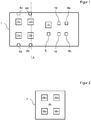
- FIG 4 the basic unit of a second embodiment of a device according to the invention is shown.
- the basic unit assigns the same structure as that except for a few changes Figure 1 described first embodiment. To avoid repetition, only the main differences are discussed below:
- the basic unit of the second exemplary embodiment has only one optical detector 2e.
- the optical detector 2e has a large detection area which comprises the entire area which is covered by the detection areas of the optical detectors 2a to 2d of the first exemplary embodiment.
- the basic unit of the second exemplary embodiment is also for use with a detection unit 7 according to Figure 2 educated.
- the detection unit 7 is arranged on the base unit 1 by means of the detents 6a to 6d, the detection areas 9a to 9d are all located over the large-area detection area of the optical detector 2e, so that light passing through the detection areas 9a to 9d strikes the optical detector 2e .
- the optical detector 2e is designed as a spectrally resolving RGB sensor.
- the detection areas 9a to 9d are designed such that a color change takes place in different spectral areas.
- the optical detector 2e as a spectrally resolving detector, a color change can thus be determined separately for each detection range 9a to 9d based on the measurement data of the sensor, since a change in the spectrum can be assigned to the respective spectral range of the detection range due to the spectral resolution.
Abstract
Die Erfindung betrifft eine Vorrichtung zur Detektion von Schimmelpilzbefall, mit zumindest einem ersten Detektionsbereich mit einem ersten sensitiven Farbstoff und einem zweiten Detektionsbereich mit einem zu dem ersten Farbstoff verschiedenen zweiten sensitiven Farbstoff, wobei erster und zweiter Farbstoff jeweils in eine Trägermatrix eingebettet sind, der erste Farbstoff ausgebildet ist, seine Farbe abhängig von einer Zielgaskonzentration eines ersten Zielgases zu ändern und der zweite Farbstoff ausgebildet ist, seine Farbe abhängig von der Zielgaskonzentration eines zweiten, zu dem ersten unterschiedlichen Zielgases und/oder einer Änderung des pH-Wertes zu ändern. Die Erfindung betrifft weiterhin ein Verfahren zur Detektion von Schimmelpilzbefall.The invention relates to a device for the detection of mold infestation, with at least a first detection area with a first sensitive dye and a second detection area with a second sensitive dye different from the first dye, the first and second dye each being embedded in a carrier matrix, the first dye is designed to change its color depending on a target gas concentration of a first target gas and the second dye is designed to change its color depending on the target gas concentration of a second, different from the first target gas and / or a change in pH. The invention further relates to a method for the detection of mold infestation.
Description
Schimmelpilzspuren sind überall in der Umwelt vorhanden. Schimmelwachstum wird durch eine erhöhte Luftfeuchtigkeit und entsprechendes Nährstoffangebot begünstigt. Deutschlandweit sind mehr als 20 % der Privatwohnungen und -häuser mit Schimmel belastet. In Innenräumen erfolgt aufgrund zunehmender Dämmung, Baumängeln wie Kältebrücken oder falschem Lüftungsverhalten eine starke Vermehrung auf unterschiedlichen Oberflächen. Diese führt zu einer geänderten Schimmelpilzzusammensetzung und letztendlich zu einer veränderten Luftbelastung. Neben den baulichen Schäden sind gesundheitliche Auswirkungen auf den Menschen problematisch. Schimmelpilze führen zu Geruchsbelästigungen, verursachen Allergien und die entstehenden Mykotoxine (Stoffwechselprodukte) sowie Glukane (Zellbestandteile) wirken toxisch.Traces of mold are everywhere in the environment. Mold growth is promoted by increased air humidity and the corresponding nutrient supply. In Germany, more than 20% of private apartments and houses are contaminated with mold. Due to increasing insulation, construction defects such as cold bridges or incorrect ventilation behavior, there is a strong increase in the number of different surfaces indoors. This leads to a change in the mold composition and ultimately to a change in the air pollution. In addition to the structural damage, health effects on people are problematic. Molds lead to unpleasant smells, cause allergies and the mycotoxins (metabolic products) and glucans (cell components) are toxic.
Es sind Messverfahren zur Detektion von Schimmelpilzbefall bekannt, welche auf der Ansaugung von Umgebungsluft und dadurch Sammlung von Sporen auf Agar- bzw. Nährböden oder präparierten Objektträgern basieren. Nach einer Inkubationszeit von typischerweise mehreren Tagen erfolgt eine Auszählung der ggf. gewachsenen Kolonien. Verfahren, die ausschließlich auf den Messungen von solchen MVOCs (Microbial Volatile Organic Compound) basieren, können zu Fehlinterpretationen führen, da nicht unterschieden wird, ob es sich um schimmelbedingte MVOCs (microbial volatile organic compounds) oder um VOCs von Reinigungsmitteln, Möbeln oder Kosmetika mit ähnlicher Zusammensetzung handelt.Measuring methods for the detection of mold infestation are known, which are based on the suction of ambient air and thereby collection of spores on agar or nutrient media or prepared specimen slides. After an incubation period of typically several days, the colonies that may have grown are counted. Processes that are based exclusively on the measurements of such MVOCs (Microbial Volatile Organic Compound) can lead to misinterpretations, since no distinction is made between whether they are mold-related MVOCs (microbial volatile organic compounds) or VOCs of cleaning agents, furniture or cosmetics a similar composition.
Ebenso sind Verfahren zum Nachweis von Schimmel-Stoffwechselprodukten bekannt, bei welchen halbleitende Metalloxidsensoren oder analytische Gaschromatographen verwendet werden.Methods for the detection of mold metabolism products are also known, in which semiconducting metal oxide sensors or analytical gas chromatographs are used.
Aus
Aus
Die Analyse mittels der vorgenannten Methoden ist zeitintensiv und aufwendig, sodass hohe Kosten und insbesondere eine lange Wartezeit für den Benutzer entstehen.The analysis using the aforementioned methods is time-consuming and complex, so that high costs and, in particular, a long waiting time arise for the user.
Der Erfindung liegt daher die Aufgabe zugrunde, eine Vorrichtung und ein Verfahren zur Detektion von Schimmelpilzbefall zur Verfügung zu stellen, welche eine zeitnahe Auswertung ermöglichen, ohne dass aufwendige Laborgeräte und Analyseverfahren benötigt werden.The invention is therefore based on the object of providing a device and a method for detecting mold infestation, which enable timely evaluation without the need for complex laboratory equipment and analysis methods.
Gelöst ist diese Aufgabe durch eine Vorrichtung zur Detektion von Schimmelpilzbefall gemäß Anspruch 1, ein Verfahren zur Detektion von Schimmelpilzbefall gemäß Anspruch 14 sowie eine Verwendung von zumindest zwei unterschiedlich sensitiven Farbstoffen gemäß Anspruch 15. Vorteilhafte Ausgestaltungen finden sich in den abhängigen Unteransprüchen.This object is achieved by a device for the detection of mold infestation according to
Die erfindungsgemäße Vorrichtung ist bevorzugt zur Durchführung des erfindungsgemäßen Verfahrens ausgebildet, insbesondere einer bevorzugten Ausführungsform hiervon. Das erfindungsgemäße Verfahren ist bevorzugt zur Durchführung mittels der erfindungsgemäßen Vorrichtung ausgebildet, insbesondere einer bevorzugten Ausführungsform hiervon.The device according to the invention is preferably designed to carry out the method according to the invention, in particular a preferred embodiment thereof. The method according to the invention is preferably designed to be carried out by means of the device according to the invention, in particular a preferred embodiment thereof.
Der vorliegenden Erfindung liegt die Erkenntnis zugrunde, dass eine zeitnahe und kostengünstige Detektion von Schimmelpilzbefall durch Verwendung eines sensitiven Farbstoffes möglich ist. Untersuchungen zeigten jedoch, dass für eine hinreichende Genauigkeit zumindest zwei separate Detektionsvorgänge durchzuführen sind: Der vorliegenden Erfindung liegt daher die Verwendung von zumindest zwei unterschiedlichen sensitiven Farbstoffen zur Detektion von Schimmelpilzbefall zugrunde:
Die erfindungsgemäße Vorrichtung zur Detektion von Schimmelpilzbefall weist zumindest einen ersten Detektionsbereich mit einem ersten sensitiven Farbstoff und einen zweiten Detektionsbereich mit einem zu dem ersten Farbstoff verschiedenen zweiten sensitiven Farbstoff auf. Erster und zweiter Farbstoff sind jeweils in eine Trägermatrix eingebettet.The present invention is based on the knowledge that a timely and inexpensive detection of mold infestation is possible by using a sensitive dye. However, investigations showed that at least two separate detection processes must be carried out for sufficient accuracy: the present invention is therefore the use of based on at least two different sensitive dyes for the detection of mold infestation:
The device according to the invention for the detection of mold infestation has at least a first detection area with a first sensitive dye and a second detection area with a second sensitive dye different from the first dye. The first and second dyes are each embedded in a carrier matrix.
Der erste Farbstoff ist ausgebildet, seine Farbe abhängig von einer Zielgaskonzentration eines ersten Zielgases zu ändern und der zweite Farbstoff ist ausgebildet, seine Farbe abhängig von der Zielgaskonzentration eines zweiten, zu dem ersten Zielgas unterschiedlichen Zielgases und/oder eine Änderung des pH-Wertes zu ändern.The first dye is designed to change its color depending on a target gas concentration of a first target gas and the second dye is designed to change its color depending on the target gas concentration of a second target gas different from the first target gas and / or a change in the pH value .
Die Kombination der Detektion einer Zielgaskonzentration des ersten Zielgases mittels des ersten Farbstoffes mit der Detektion einer Zielgaskonzentration des zweiten Zielgases und/oder einer Änderung des pH-Wertes mittels des zweiten Farbstoffes ermöglicht eine hinreichend genaue Detektion von Schimmelpilzbefall und ist gegenüber den aus dem Stand der Technik bekannten Methoden zur Detektion von Schimmelpilzbefall erheblich unaufwendiger durchführbar. Insbesondere werden keine aufwendigen Apparaturen wie beispielsweise Gaschromatographen benötigt. Weiterhin ist kein Einsenden einer Probe oder eines Absorbers in ein Analyselabor notwendig, da eine Änderung der Farbe des ersten und des zweiten Farbstoffes mit einfachen Mitteln auch unmittelbar am Ort der Messung festgestellt werden kann.The combination of the detection of a target gas concentration of the first target gas by means of the first dye with the detection of a target gas concentration of the second target gas and / or a change in the pH value by means of the second dye enables a sufficiently precise detection of mold infestation and is compared to those from the prior art known methods for the detection of mold infestation can be carried out considerably less expensively. In particular, no expensive equipment such as gas chromatographs are required. Furthermore, it is not necessary to send a sample or an absorber to an analysis laboratory, since a change in the color of the first and the second dye can also be determined by simple means directly at the location of the measurement.
Das erfindungsgemäße Verfahren zur Detektion von Schimmelpilzbefall weist folgende Verfahrensschritte auf:
In einem Verfahrensschritt A erfolgt ein Bereitstellen zumindest eines ersten Detektionsbereiches mit einem ersten sensitiven Farbstoff und eines zweiten Detektionsbereichs mit einem zu dem ersten Farbstoff verschiedenen zweiten sensitiven Farbstoff, wobei der erste Farbstoff ausgebildet ist, seine Farbe abhängig von einer Zielgaskonzentration eines ersten Zielgases zu ändern und der zweite Farbstoff ausgebildet ist, seine Farbe abhängig von der Zielgaskonzentration eines zweiten, zu dem ersten unterschiedlichen Zielgases und/oder einer Änderung des pH-Wertes zu ändern. In einem Verfahrensschritt B erfolgt eine Analyse einer Farbänderung des ersten und des zweiten Farbstoffes.The method according to the invention for the detection of mold infestation has the following method steps:
In a method step A, at least one first detection area with a first sensitive dye and a second detection area with a second sensitive dye different from the first dye are provided, the first dye being designed to change its color depending on a target gas concentration of a first target gas and the second dye is designed to change its color depending on the target gas concentration of a second target gas different from the first and / or a change in the pH value. In a method step B, an analysis of a color change of the first and the second dye takes place.
Hierdurch werden die zuvor zu der erfindungsgemäßen Vorrichtung genannten Vorteile erzielt.This achieves the advantages mentioned above for the device according to the invention.
Untersuchungen des Anmelders zeigten, dass zur Detektion von Schimmelpilzbefall die Wahl des ersten und zweiten Farbstoffs wie folgt vorteilhaft ist: In einer vorteilhaften Ausführungsform sind erster und zweiter Farbstoff zur Detektion einer Änderung von zwei verschiedenen Parametern aus der Gruppe
- Gaskonzentration Formaldehyd;
- Gaskonzentration Dimethylsulfid;
- Gaskonzentration Ethanol;
- pH-Wert
- Gas concentration formaldehyde;
- Gas concentration dimethyl sulfide;
- Gas concentration ethanol;
- PH value
In dieser vorteilhaften Ausführungsform werden somit durch die zwei Farbstoffe zwei verschiedene der zuvor vier genannten Parameter detektiert.In this advantageous embodiment, two different of the four parameters mentioned above are thus detected by the two dyes.
Für die Detektion von Schimmelpilzspuren sowie deren Stoffwechselprodukte sind bestimmte Farbstoffe besonders geeignet. Vorteilhafterweise gehören erster und zweiter Farbstoff daher zwei unterschiedlichen der nachfolgenden Stoffgruppen an:
- gassensitive Farbstoffe aus der Gruppe der Naphthaline, insbesondere zur Detektion einer Änderung der Gaskonzentration von Formaldehyd;
- gassensitive Farbstoffe aus der Gruppe der Metallsalze, insbesondere zur Detektion einer Änderung der Gaskonzentration von Dimethylsulfid;
- gassensitive Farbstoffe aus der Gruppe der Übergangsmetallkomplexe, insbesondere zur Detektion einer Änderung der Gaskonzentration von Ethanol;
- pH-sensitive Farbstoffe, insbesondere zur Detektion einer Änderung des pH-Wertes des Farbstoffs.
- gas-sensitive dyes from the group of naphthalenes, in particular for detecting a change in the gas concentration of formaldehyde;
- gas-sensitive dyes from the group of the metal salts, in particular for the detection of a change in the gas concentration of dimethyl sulfide;
- gas-sensitive dyes from the group of transition metal complexes, in particular for detecting a change in the gas concentration of ethanol;
- pH-sensitive dyes, especially for the detection of a change in the pH of the dye.
Insbesondere die Wahl von erstem und zweitem Farbstoff gemäß der vorgenannten vorteilhaften Ausführungsformen ermöglicht eine hinreichend genaue und dennoch kostengünstige und zeitsparende Detektion von Schimmelpilzbefall.In particular, the choice of the first and second dye according to the aforementioned advantageous embodiments enables a sufficiently precise, yet inexpensive and time-saving detection of mold infestation.
In einer weiteren vorteilhaften Ausführungsform weist zumindest ein Detektionsbereich einen Nährboden für Schimmelpilz-Lebendkeime auf. Hierdurch ist somit zusätzlich eine Aussage über die Detektion speziell von Lebendkeimen möglich. Vorteilhafterweise weist der Detektionsbereich eine Agar-Schicht, bevorzugt eine DG18-Agar-Schicht und/oder eine Malzextrakt-Agar-Schicht auf, da diese sich besonders als Nährboden für Schimmelpilz-Lebendkeime eignen. Vorteilhafterweise ist dieser Detektionsbereich zur Detektion einer Änderung des pH-Wertes des Nährbodens ausgebildet, sodass in unaufwendiger Weise mittels einer Detektion einer Änderung des pH-Wertes das Vorliegen von Schimmelpilz-Lebendkeime detektiert werden kann.In a further advantageous embodiment, at least one detection area has a culture medium for live mold fungi. This also makes it possible to make a statement about the detection of live germs in particular. The detection area advantageously has an agar layer, preferably a DG18 agar layer and / or a malt extract agar layer, since these are particularly suitable as a breeding ground for mold fungi living germs. This detection area is advantageously designed to detect a change in the pH of the nutrient medium, so that the presence of mold fungi can be detected in an uncomplicated manner by means of a change in the pH.
In einer weiteren vorteilhaften Ausführungsform sind erster und/oder zweiter Detektionsbereich zur optischen Transmissionsmessung ausgebildet. Dies ermöglicht eine unaufwendige und dennoch fehlerunanfällige Detektion einer Farbänderung. Bevorzugt sind daher beide Detektionsbereiche zur optischen Transmissionsmessung ausgebildet. Insbesondere ist es vorteilhaft, dass der oder die zur optischen Transmissionsmessung ausgebildeten Detektionsbereiche eine optisch transparente Trägermatrix aufweisen. In dieser vorteilhaften Ausführungsform ist der Farbstoff somit in die optisch transparente Trägermatrix eingebettet, sodass in robuster und kostenunaufwendiger Weise eine optische Transmissionsmessung zur Detektion einer Farbänderung ermöglicht wird.In a further advantageous embodiment, the first and / or second detection area are designed for optical transmission measurement. This enables an uncomplicated but error-prone detection of a color change. Both detection areas are therefore preferably designed for optical transmission measurement. In particular, it is advantageous that the detection area or areas designed for optical transmission measurement have an optically transparent carrier matrix. In this advantageous embodiment, the dye is thus embedded in the optically transparent carrier matrix, so that an optical transmission measurement for detecting a color change is made possible in a robust and inexpensive manner.
Vorteilhafterweise sind erster und/oder zweiter, insbesondere beide Farbstoffe, für eine Farbänderung im sichtbaren Wellenlängenbereich zur Detektion des jeweiligen Zielparameters ausgebildet. Hierdurch ist eine Farbänderung in unaufwendiger Weise möglich. Insbesondere kann in einer besonders kostengünstigen vorteilhaften Ausgestaltung die Farbänderung durch den Benutzer mittels Betrachten detektiert werden. Insbesondere ist es vorteilhaft, dass die Vorrichtung zusätzlich eine oder mehrere Farbskalen umfasst, welche dem Benutzer durch Farbvergleich ein Feststellen einer Farbänderung des Farbstoffes vereinfachen.The first and / or second, in particular both, dyes are advantageously for a color change in the visible wavelength range for the detection of the respective target parameters. This enables a color change in an uncomplicated manner. In particular, in a particularly inexpensive, advantageous embodiment, the color change can be detected by the user by viewing. In particular, it is advantageous that the device additionally comprises one or more color scales, which make it easier for the user to determine a change in color of the dye by comparing the colors.
Vorteilhafterweise weist die Vorrichtung zumindest einen optischen Sensor zur Detektion einer Farbänderung des ersten und/oder des zweiten Farbstoffs, insbesondere zur Detektion einer Farbänderung beider Farbstoffe auf. Hierdurch ist eine automatische Auswertung insbesondere auch in Abwesenheit des Benutzers möglich. Weiterhin werden fehlerhafte Auswertungen durch eine falsche Interpretation einer Farbänderung durch den Benutzer vermieden.The device advantageously has at least one optical sensor for detecting a change in color of the first and / or second dye, in particular for detecting a change in color of both dyes. This enables an automatic evaluation, particularly in the absence of the user. Furthermore, incorrect evaluations due to an incorrect interpretation of a color change by the user are avoided.
Vorteilhafterweise weist die Vorrichtung für jeden der beiden Detektionsbereiche einen separaten optischen Sensor auf. Hierdurch kann für jeden Detektionsbereich der jeweils zugeordnete optische Sensor für die bei dem zugeordneten Detektionsbereich zu erwartende Farbänderung optimiert werden.The device advantageously has a separate optical sensor for each of the two detection areas. In this way, the assigned optical sensor for each detection area can be optimized for the color change to be expected in the assigned detection area.
Der optische Sensor ist in einer bevorzugten Ausführungsform ausgebildet, eine Intensitätsänderung und/oder Änderung des Spektrums des von dem ersten und/oder zweiten Farbstoffs reflektierten und/oder transmittierten Lichts ausgebildet.In a preferred embodiment, the optical sensor is designed, a change in intensity and / or change in the spectrum of the light reflected and / or transmitted by the first and / or second dye is formed.
Der optische Sensor ist bevorzugt zur Spektralanalyse ausgebildet. Insbesondere ist der optische Sensor bevorzugt als Farbsensor, insbesondere einen mehrkanaligen Farbsensor, bevorzugt einen RGB-Farbsensor ausgebildet. Hierdurch wird in kostengünstiger und fehlerunanfälliger Weise eine Detektion einer Farbänderung ermöglicht, die wesentlich genauer ist als beispielsweise eine Auswertung lediglich basierend auf einer Betrachtung durch den Benutzer. Bevorzugt ist der optische Sensor zur Änderung des Spektrums des von dem ersten und/oder zweiten Farbstoffs reflektierten und/oder transmittierten Lichts ausgebildet.The optical sensor is preferably designed for spectral analysis. In particular, the optical sensor is preferably designed as a color sensor, in particular a multi-channel color sensor, preferably an RGB color sensor. This enables a color change to be detected in a cost-effective and error-prone manner, which is much more precise than, for example, an evaluation based solely on an observation by the user. The optical sensor is preferably designed to change the spectrum of the light reflected and / or transmitted by the first and / or second dye.
In einer vorteilhaften Ausgestaltung ist für jeden Detektionsbereich jeweils ein optischer Sensor zur Analyse einer Farbänderung des jeweiligen Detektionsbereiches vorgesehen. Hierdurch ergibt sich der Vorteil, dass die Sensoren auf die jeweilige Farbänderung des Detektionsbereichs abgestimmt werden können und für jeden Detektionsbereich separate Messsignale vorliegen.In an advantageous embodiment, an optical sensor for analyzing a color change of the respective detection area is provided for each detection area. This has the advantage that the sensors can be matched to the respective color change of the detection area and that separate measurement signals are available for each detection area.
In einer weiteren vorteilhaften Ausführungsform ist der optische Sensor derart ausgebildet und angeordnet, um eine Farbänderung sowohl des ersten, als auch des zweiten Detektionsbereiches zu detektieren. Insbesondere ist der optische Detektor vorteilhafterweise derart ausgebildet und angeordnet, dass transmittiertes und/oder reflektiertes Licht von dem ersten und dem zweiten Detektionsbereich auf eine Detektionsfläche des Detektors fällt. In diesem Fall ist es insbesondere vorteilhaft, dass die Farbänderung im ersten Detektionsbereich in einem anderen Wellenlängenbereich erfolgt als die Farbänderung in dem zweiten Detektionsbereich und der Sensor zur spektralen Differenzierung ausgebildet ist, so dass anhand der Messsignale des Detektors zwischen einer Farbänderung im ersten Detektionsbereich und einer Farbänderung im zweiten Detektionsbereich unterschieden werden kann.In a further advantageous embodiment, the optical sensor is designed and arranged to detect a color change in both the first and the second detection area. In particular, the optical detector is advantageously designed and arranged such that transmitted and / or reflected light from the first and the second detection area falls on a detection surface of the detector. In this case, it is particularly advantageous that the color change in the first detection range takes place in a different wavelength range than the color change in the second detection range and the sensor is designed for spectral differentiation, so that, based on the measurement signals of the detector, a color change in the first detection range and one Color change in the second detection area can be distinguished.
Die Messsignale eines Sensors können durch Lichtverhältnisse oder durch eine Veränderung der Eigenschaften der optisch transparenten Materialien und/oder des Sensors durch äußere Einflüsse wie etwa Temperatur und Feuchtigkeit beeinflusst werden. In einer vorteilhaften Ausführungsform weist die Vorrichtung daher zumindest einen Referenzbereich auf, welcher derart angeordnet und mit dem optischen Sensor zusammenwirkend ausgebildet ist, dass den Referenzbereich durchdringende Lichtstrahlen und/oder von dem Referenzbereich reflektierte Lichtstrahlen auf den optischen Sensor auftreffen. Hierdurch ist somit eine Kalibrierung oder zumindest eine Fehlerkorrektur bei Auswerten der Messdaten des optischen Sensors möglich.The measurement signals of a sensor can be influenced by light conditions or by a change in the properties of the optically transparent materials and / or the sensor by external influences such as temperature and humidity. In an advantageous embodiment, the device therefore has at least one reference area, which is arranged and designed to interact with the optical sensor such that light rays penetrating the reference area and / or light rays reflected from the reference area strike the optical sensor. This enables calibration or at least error correction when evaluating the measurement data of the optical sensor.
Es liegt im Rahmen der Erfindung, dass die Referenzmessung erfolgt, während der Lichtweg über den Farbstoff zu dem Sensor blockiert ist. Dies kann dadurch erfolgen, dass der Benutzer während der Referenzmessung die Messbereiche abdeckt, insbesondere mit einer Referenz-Abdeckplatte der erfindungsgemäßen Vorrichtung abdeckt. Ebenso liegt es im Rahmen der Erfindung, dass in einer alternativen Ausführungsform gleichzeitig Lichtstrahlen einerseits über den Referenzbereich und andererseits über den Detektionsbereich auf den Sensor auftreffen.It is within the scope of the invention that the reference measurement takes place while the light path via the dye to the sensor is blocked. This can be done by the user covering the measuring ranges during the reference measurement, in particular covering them with a reference cover plate of the device according to the invention. It is also within the scope of the invention that in a alternative embodiment, at the same time light rays strike the sensor on the one hand via the reference range and on the other hand via the detection range.
Der Referenzbereich weist vorteilhafterweise keinen Farbstoff oder einen nichtsensitiven Farbstoff, insbesondere einen nicht auf eine Änderung der Gaskonzentration des Zielgases und/oder nicht auf eine pH-Wertänderung sensitiven Farbstoff auf. Hierdurch wird eine Kalibrierung oder zumindest Fehlerkorrektur unabhängig von einem Auftreffen von Schimmelpilzspuren auf den Referenzbereich ermöglicht. Insbesondere ist es vorteilhaft, dass der Referenzbereich die gleiche Trägermatrix wie zumindest einer der Detektionsbereiche aufweist. Hierdurch ist ein konstruktiv einfacher Aufbau gegeben.The reference range advantageously has no dye or a non-sensitive dye, in particular a dye that is not sensitive to a change in the gas concentration of the target gas and / or not to a change in pH. This enables calibration or at least error correction regardless of the occurrence of mold traces on the reference area. In particular, it is advantageous that the reference area has the same carrier matrix as at least one of the detection areas. This gives a structurally simple structure.
In einer weiteren vorteilhaften Ausführungsform weist die Vorrichtung zumindest einen Feuchtesensor, insbesondere einen Feuchtedetektionsbereich mit einem feuchtesensitiven Farbstoff und/oder zumindest einen Temperatursensor, insbesondere einen Temperaturdetektionsbereich mit einem temperatursensitiven Farbstoff auf.In a further advantageous embodiment, the device has at least one moisture sensor, in particular a moisture detection area with a moisture-sensitive dye and / or at least one temperature sensor, in particular a temperature detection area with a temperature-sensitive dye.
Die Kombination der Messergebnisse von erstem und zweitem Farbstoff mit einer Feuchtemessung und/oder mit einer Temperaturmessung, insbesondere sowohl mit einer Feuchtemessung als auch mit einer Temperaturmessung, ermöglicht eine höhere Präzision bei der Detektion des Schimmelpilzbefalls.The combination of the measurement results of the first and second dye with a moisture measurement and / or with a temperature measurement, in particular both with a moisture measurement and with a temperature measurement, enables a higher precision in the detection of the mold attack.
In einer besonders benutzerfreundlichen Ausführungsform ist die Vorrichtung zur automatisierten Auswertung ausgebildet:
Vorteilhafterweise weist die Vorrichtung eine Grundeinheit auf, mit dem zumindest einen optischen Sensor und mit einer Auswerteeinheit sowie bevorzugt mit einer Energiequelle zumindest für die Auswerteeinheit. Die Auswerteeinheit ist mit dem optischen Sensor zur Auswertung von Messdaten des optischen Sensors, insbesondere zur Detektion eines Schimmelpilzbefalls, zusammenwirkend ausgebildet.In a particularly user-friendly embodiment, the device is designed for automated evaluation:
The device advantageously has a basic unit with the at least one optical sensor and with an evaluation unit and preferably with an energy source at least for the evaluation unit. The evaluation unit is designed to cooperate with the optical sensor for evaluating measurement data from the optical sensor, in particular for detecting a mold attack.
Die Vorrichtung weist in dieser vorteilhaften Ausführungsform weiterhin eine Detektionseinheit mit zumindest dem ersten und dem zweiten Detektionsbereich auf, wobei die Detektionseinheit lösbar an der Grundeinheit anordenbar ist. Insbesondere ist die Detektionseinheit bevorzugt mittels zumindest eines Befestigungselementes, bevorzugt einer Nut und/oder eines Rastelements, lösbar an der Grundeinheit anordenbar.In this advantageous embodiment, the device also has a detection unit with at least the first and the second detection area on, the detection unit being releasably arranged on the base unit. In particular, the detection unit can preferably be detachably arranged on the base unit by means of at least one fastening element, preferably a groove and / or a latching element.
Hierdurch ergibt sich der Vorteil, dass durch Austausch der Detektionseinheit die Grundeinheit wiederverwendet werden kann. Hierdurch wird zur Durchführung mehrerer Messungen eine erhebliche Kostenersparnis erzielt, da bei Verbrauch oder Fehlfunktion der Detektionseinheit lediglich diese ausgetauscht werden muss. Dies ist insbesondere vorteilhaft, da typischerweise der optische Sensor sowie die Auswerteeinheit für eine sehr große Anzahl von Auswertungen verwendet werden können, wobei die Detektionseinheit, insbesondere die Farbstoffe bereits nach einer oder zumindest nach einer wesentlich geringeren Anzahl von Messungen ausgetauscht werden sollten.This has the advantage that the basic unit can be reused by exchanging the detection unit. This results in considerable cost savings for carrying out several measurements, since only the detection unit needs to be replaced when it is used or malfunctioning. This is particularly advantageous since the optical sensor and the evaluation unit can typically be used for a very large number of evaluations, the detection unit, in particular the dyes, being to be replaced after one or at least after a significantly smaller number of measurements.
Grundsätzlich liegt die Verwendung von sensitiven Farbstoffen mit irreversibler Farbänderung im Rahmen der Erfindung. Besonders vorteilhaft ist jedoch die Verwendung von sensitiven Farbstoffen mit reversibler Farbänderung, um eine Verwendung für mehrere Messungen zu ermöglichen.Basically, the use of sensitive dyes with irreversible color changes is within the scope of the invention. However, the use of sensitive dyes with reversible color change is particularly advantageous in order to enable use for several measurements.
Insbesondere ist es vorteilhaft, die sensitiven Farbstoffe mit irreversibler Farbänderung vorzusehen, so dass das Messergebnis dauerhaft auslesbar ist.In particular, it is advantageous to provide the sensitive dyes with an irreversible color change, so that the measurement result can be read out permanently.
Vorteilhafterweise weist die Vorrichtung eine Anzeigeeinheit auf, welche mit der Auswerteeinheit zusammenliegend ausgebildet ist, um ein Auswerteergebnis der Auswerteeinheit anzuzeigen. In kostensparender Weise kann die Anzeigeeinheit zumindest ein optisches Leuchtmittel aufweisen. Besonders kostensparende Ausgestaltungen werden durch die Verwendung von lediglich einem oder von zwei optischen Leuchtmitteln erzielt. Insbesondere ist es kostensparend, eine oder mehrere Dioden als optisches Leuchtmittel zu verwenden.Advantageously, the device has a display unit which is designed to lie together with the evaluation unit in order to display an evaluation result of the evaluation unit. The display unit can have at least one optical illuminant in a cost-saving manner. Particularly cost-saving designs are achieved by using only one or two optical lamps. In particular, it is cost-saving to use one or more diodes as the optical illuminant.
Eine besonders einfache und kostengünstige Ausgestaltung wird durch die Verwendung von zwei optischen Leuchtmitteln erzielt, welche mit der Auswerteeinheit verbunden sind. Die Auswerteeinheit ist derart ausgebildet, dass bei Detektion von Schimmelpilzbefall das eine, hingegen bei Ausbleiben eines solchen Detektionsergebnisses das andere Leuchtmittel leuchtet. Eine besonders benutzerfreundliche Ausgestaltung ergibt sich durch die Verwendung eines roten Leuchtmittels zur Anzeige eines detektierten Schimmelpilzbefalls und eines grünen Leuchtmittels zur Anzeige, dass kein Schimmelpilzbefall detektiert wurde.A particularly simple and inexpensive embodiment is achieved by using two optical illuminants which are connected to the evaluation unit. The evaluation unit is designed in such a way that the one illuminant illuminates when mold is attacked, but the other illuminant illuminates when there is no such detection result. A Particularly user-friendly design results from the use of a red illuminant to indicate a detected mold infestation and a green illuminant to indicate that no mold infestation has been detected.
In einer vorteilhaften Ausführungsform ist die erfindungsgemäße Vorrichtung dazu ausgebildet, mittels des zumindest eines optischen Sensors unter Verwendung des Umgebungslichts die Messung durchzuführen. Hierdurch ergibt sich der Vorteil, dass keine zusätzliche Lichtquelle erforderlich ist.In an advantageous embodiment, the device according to the invention is designed to carry out the measurement by means of the at least one optical sensor using the ambient light. This has the advantage that no additional light source is required.
In einer alternativen vorteilhaften Ausgestaltung weist die erfindungsgemäße Vorrichtung zusätzlich zumindest eine Messlichtquelle, insbesondere eine Leuchtdiode, auf, welche derart angeordnet ist, dass von der Messlichtquelle erzeugtes Messlicht auf die Detektionsbereiche und nach Transmission und/oder Reflexion an den Detektionsbereichen auf den oder die optischen Sensoren auftrifft, so dass eine Durchführung der Messung mittels des Lichts der Messlichtquelle erfolgt. Hierdurch ergibt sich eine vorteilhafte Unabhängigkeit von Umgebungslicht und insbesondere kann die Messgenauigkeit erhöht werden, da definierte und vorbekannte Beleuchtungsverhältnisse vorliegen.In an alternative advantageous embodiment, the device according to the invention additionally has at least one measurement light source, in particular a light-emitting diode, which is arranged such that measurement light generated by the measurement light source is applied to the detection areas and, after transmission and / or reflection at the detection areas, to the optical sensor or sensors strikes so that the measurement is carried out by means of the light of the measurement light source. This results in an advantageous independence from ambient light and, in particular, the measurement accuracy can be increased, since defined and previously known lighting conditions are present.
Eine weitere Erhöhung der Detektionsgenauigkeit wird in einer vorteilhaften Ausgestaltung dadurch erzielt, dass die Vorrichtung mehr als zwei Detektionsbereiche mit jeweils einem in eine Trägermatrix eingebetteten sensitiven Farbstoff aufweist, wobei die sensitiven Farbstoffe teilweise unterschiedlich sind. Insbesondere ist es vorteilhaft, dass die Vorrichtung zumindest vier Detektionsbereiche mit teilweise unterschiedlichen Farbstoffen aufweist.In an advantageous embodiment, a further increase in the detection accuracy is achieved in that the device has more than two detection areas, each with a sensitive dye embedded in a carrier matrix, the sensitive dyes being partially different. In particular, it is advantageous that the device has at least four detection areas with partially different dyes.
Besonders bevorzugt weist die Vorrichtung zumindest jeweils einen Farbstoff zur Detektion der Gaskonzentration von Formaldehyd, von Dimethylsulfid, von Ethanol und der Änderung des pH-Wertes auf.The device particularly preferably has at least one dye in each case for the detection of the gas concentration of formaldehyde, of dimethyl sulfide, of ethanol and the change in the pH.
Die eingangs erwähnte Aufgabe ist somit insbesondere durch die Verwendung von zumindest zwei unterschiedlichen sensitiven Farbstoffen zur Detektion von Schimmelpilzbefall gelöst.The object mentioned at the outset is thus achieved in particular by using at least two different sensitive dyes for the detection of mold infestation.
In einer besonders vorteilhaften Ausgestaltung ist die Vorrichtung als Gassensorsystem ausgebildet, mit einem gassensitiven Etikett, insbesondere Einwegetikett, als Detektionseinheit sowie einer Grundeinheit, welche mehrere Farbsensoren, insbesondere mehrkanalige Farbsensoren, eine oder mehrere Mikrooptiken zur Leitung des die Detektionsbereiche des Etiketts durchdringenden Lichtes zu jeweils einem zugeordneten Farbsensor sowie eine als elektronische Recheneinheit ausgebildete Auswerteeinheit aufweist. Vorteilhafterweise weist das Gesamtsystem eine Grundfläche auf, die kleiner als DIN A5 (148 mm x 210 mm) ist. Das zuvor beschriebene Etikett weist damit mehrere Detektionsbereiche auf, die jeweils als kolorimetrische Sensoren ausgebildet sind, in denen wie zuvor beschrieben die Farbe des jeweiligen Detektionsbereiches sich selektiv in Abhängigkeit des jeweils zugeordneten Zielgases und/oder pH-Wertes ändert. Die Farbstoffe sind jeweils in eine Trägermatrix, insbesondere ein Polymer, integriert.In a particularly advantageous embodiment, the device is designed as a gas sensor system, with a gas-sensitive label, in particular a disposable label, as a detection unit and a basic unit which has a plurality of color sensors, in particular multi-channel color sensors, one or more micro-optics for guiding the light penetrating the detection areas of the label into one in each case assigned color sensor and an evaluation unit designed as an electronic computing unit. The overall system advantageously has a base area that is smaller than DIN A5 (148 mm × 210 mm). The label described above thus has a plurality of detection areas, each of which is designed as a colorimetric sensor, in which, as previously described, the color of the respective detection area changes selectively depending on the respectively assigned target gas and / or pH value. The dyes are each integrated in a carrier matrix, in particular a polymer.
Vorteilhafterweise werden die Detektionsbereiche durch Aufbringen planarer Schichten auf einen transparenten Träger, insbesondere Glas oder polymerbasierte Substrate, bevorzugt PMMA oder Folien, hergestellt. Wie zuvor beschrieben, werden weiterhin auf dem transparenten Träger separate Referenzflächen, beispielsweise nur mit der Matrix ohne einen sensitiven Farbstoff oder mit einem inaktiven Farbstoff, beschichtet.The detection areas are advantageously produced by applying planar layers to a transparent support, in particular glass or polymer-based substrates, preferably PMMA or foils. As described above, separate reference areas are furthermore coated on the transparent support, for example only with the matrix without a sensitive dye or with an inactive dye.
Die Auswertung erfolgt bevorzugt derart, dass dann ein Schimmelpilzbefall detektiert wird, wenn bei allen Detektionsbereichen eine zuvor definierte Farbänderung erfolgt.The evaluation is preferably carried out in such a way that a mold attack is detected if a previously defined color change takes place in all detection areas.
Weitere vorteilhafte Merkmale und Ausführungsformen werden im Folgenden anhand von einem Ausführungsbeispiel und den Figuren erläutert. Dabei zeigt:
Figur 1- die Grundeinheit eines ersten Ausführungsbeispiels einer erfindungsgemäßen Vorrichtung;
- Figur 2
- die Detektionseinheit des ersten Ausführungsbeispiels,
Figur 3- eine Schnittdarstellung gemäß Linie A in
Figur 1 - Figur 4
- eine Grundeinheit eines zweiten Ausführungsbeispiels einer erfindungsgemäßen Vorrichtung.
- Figure 1
- the basic unit of a first embodiment of a device according to the invention;
- Figure 2
- the detection unit of the first exemplary embodiment,
- Figure 3
- a sectional view along line A in
Figure 1 and perpendicular to the drawing surface with the detection unit arranged on the base unit and - Figure 4
- a basic unit of a second embodiment of a device according to the invention.
Die Figuren zeigen schematische, nicht maßstabsgetreue Darstellungen. Gleiche Bezugszeichen in den Figuren bezeichnen gleiche oder gleich wirkende Elemente.The figures show schematic representations that are not to scale. The same reference numerals in the figures denote the same or equivalent elements.
In
Die Grundeinheit weist vier optische Detektoren 2a, 2b, 2c und 2d auf. Jeder optische Detektor ist als RGB-Farbsensor ausgebildet.The basic unit has four
Die Grundeinheit 1 weist weiterhin eine Auswerteeinheit 3 auf. Diese ist als einfache Rechnereinheit ausgebildet, mit einem Rechenprozessor und einer Speichereinheit, insbesondere für ein Auswerteprogramm. Die Grundeinheit 1 weist weiterhin zwei Leuchtmittel auf: eine grüne LED 4a und eine rote LED 4b.The
Die Auswerteeinheit 3 ist mit den optischen Detektoren 2a bis 2d verbunden, um deren Messwerte auszulösen. Weiterhin ist die Auswerteeinheit 3 mit den Leuchtmitteln 4a und 4b verbunden, um mittels der Leuchtmittel ein Ergebnis der Auswertung anzuzeigen. Die Grundeinheit 1 weist weiterhin eine als Batterie ausgebildete Energiequelle 5 auf, welche mit der Auswerteeinheit zur Energieversorgung verbunden ist.The
Weiterhin weist die Grundeinheit 1 vier Rastnasen 6a, 6b, 6c und 6d auf, um eine Detektionseinheit mittels der Rastnasen an der Grundeinheit 1 über den optischen Detektoren 2a bis 2d anzuordnen: In
Detektionsbereiche 9a, 9b, 9c und 9d ausgebildet, bei denen jeweils in einem Polymer als Trägermatrix folgende sensitiven Farbstoffe eingebettet sind:
Jeder dieser Farbstoffe kann somit seine Farbe abhängig von der Zielgaskonzentration des in der Tabelle angegebenen Zielgases bzw. des pH-Wertes ändern.Each of these dyes can thus change its color depending on the target gas concentration of the target gas specified in the table or the pH value.
Die Detektionseinheit 7 ist als Einwegetikett ausgebildet und kann somit nach erfolgter Messung ausgetauscht werden. Die Grundeinheit 1 wird hingegen mit dem neuen Einwegetikett wiederverwendet.The
Zur Durchführung einer Messung wird die Detektionseinheit 7 mittels der Rastnasen 6a - 6d an der Grundeinheit 1 angeordnet, indem die Detektionseinheit 7 eingeklipst oder eingeschoben wird. In
Fällt nun Umgebungslicht auf die Detektionsbereiche 9a bis 9d so durchdringt das Licht die Detektionsbereiche sowie den optischen Träger 8 und trifft auf die optischen Detektoren 2a bis 2d auf. Zur Verstärkung des optischen Signals weisen die optischen Detektoren 2a bis 2d an der der Detektionseinheit 7 zugewandten Seite jeweils eine Mikrooptik mit Sammellinsen auf. Exemplarisch sind in
Die Messsignale der optischen Detektoren 2a bis 2d werden von der Auswerteeinheit 3 ausgelesen und hinsichtlich einer Farbänderung bewertet. Die Auswertung beginnt, sobald eine Energiequelle 5, vorliegend eine Batterie in die Grundeinheit 1 eingesetzt wird. In einer alternativen Ausgestaltung ist ein Startknopf zum Starten der Auswertung vorgesehen.The measurement signals of the
In dem vorliegenden Ausführungsbeispiel wird ein Befall von Schimmelpilz detektiert, wenn mindestens zwei der Detektionsbereiche ansprechen.In the present exemplary embodiment, an infestation of mold is detected if at least two of the detection areas respond.
Abhängig von dem Auswerteergebnis wird mittels der Auswerteeinheit 3 die rote LED 4b bei Schimmelpilzbefall und die grüne LED 4a bei nicht detektiertem Schimmelpilzbefall zum Leuchten gebracht.Depending on the evaluation result, the
In einem erweiterten Ausführungsbeispiel weist die Grundeinheit 1 zusätzlich einen Feuchtesensor 10 und einen Temperatursensor 11 auf, die ebenfalls mit der Auswerteeinheit 3 verbunden sind. Mittels der Auswerteeinheit werden in diesem Ausführungsbeispiel somit nicht nur etwaige Farbänderungen der Detektionsbereiche 9a bis 9d gemessen, sondern auch zusätzlich ein Feuchtewert mittels des Feuchtesensors 10 und ein Temperaturwert mittels des Temperatursensors 11.In an extended exemplary embodiment, the
In
Die Grundeinheit des zweiten Ausführungsbeispiels weist lediglich einen optischen Detektor 2e auf. Der optische Detektor 2e weist eine große Detektionsfläche auf, welche die gesamte Fläche umfasst, die von den Detektionsflächen der optischen Detektoren 2a bis 2d des ersten Ausführungsbeispiels abgedeckt wird. Auch die Grundeinheit des zweiten Ausführungsbeispiels ist zur Verwendung mit einer Detektionseinheit 7 gemäß
The basic unit of the second exemplary embodiment has only one
Wird die Detektionseinheit 7 mittels der Rastnasen 6a bis 6d auf der Grundeinheit 1 angeordnet, so liegen die Detektionsbereiche 9a bis 9d alle über dem großflächigen Detektionsbereich des optischen Detektors 2e, so dass durch die Detektionsbereiche 9a bis 9d durchtretendes Licht jeweils auf den optischen Detektor 2e auftrifft.If the
Der optische Detektor 2e ist als spektral auflösender RGB-Sensor ausgebildet. Die Detektionsbereiche 9a bis 9d sind derart ausgebildet, dass eine Farbänderung jeweils in unterschiedlichen Spektralbereichen erfolgt.The
Durch die Ausgestaltung des optischen Detektors 2e als spektralauflösender Detektor kann somit für jeden Detektionsbereich 9a bis 9d separat ein Farbumschlag anhand der Messdaten des Sensors ermittelt werden, da aufgrund der spektralen Auflösung eine Änderung des Spektrums dem jeweiligen Spektralbereich des Detektionsbereichs zugeordnet werden kann.By designing the
In diesem zweiten Ausführungsbeispiel ist somit lediglich ein optischer Detektor notwendig und dennoch kann eine separate Auswertung von Farbumschlägen der vier Detektionsbereiche 9a bis 9d erfolgen.In this second exemplary embodiment, only one optical detector is therefore necessary, and nevertheless a separate evaluation of color changes of the four
Claims (15)
mit zumindest einem ersten Detektionsbereich (9a, 9b, 9c, 9d) mit einem ersten sensitiven Farbstoff und einem zweiten Detektionsbereich (9a, 9b, 9c, 9d) mit einem zu dem ersten Farbstoff verschiedenen zweiten sensitiven Farbstoff,
wobei erster und zweiter Farbstoff jeweils in eine Trägermatrix eingebettet sind, der erste Farbstoff ausgebildet ist, seine Farbe abhängig von einer Zielgaskonzentration eines ersten Zielgases zu ändern und der zweite Farbstoff ausgebildet ist, seine Farbe abhängig von der Zielgaskonzentration eines zweiten, zu dem ersten unterschiedlichen Zielgases und/oder einer Änderung des pH-Wertes zu ändern.Device for the detection of mold infestation,
with at least a first detection area (9a, 9b, 9c, 9d) with a first sensitive dye and a second detection area (9a, 9b, 9c, 9d) with a second sensitive dye different from the first dye,
wherein first and second dye are each embedded in a carrier matrix, the first dye is designed to change its color depending on a target gas concentration of a first target gas and the second dye is formed, its color depending on the target gas concentration of a second, different from the first target gas and / or a change in pH.
dadurch gekennzeichnet,
dass erster und zweiter Farbstoff zur Detektion einer Änderung von zwei verschiedenen Parametern aus der Gruppe
dass erster und zweiter Farbstoff zwei unterschiedlichen aus den nachfolgenden Stoffgruppen angehören:
characterized,
that first and second dye to detect a change in two different parameters from the group
that the first and second dye belong to two different ones from the following groups of substances:
dadurch gekennzeichnet,
dass zumindest ein Detektionsbereich (9a, 9b, 9c, 9d) einen Nährboden für Schimmelpilz-Lebendkeime aufweist, insbesondere eine Agar-Schicht, bevorzugt eine DG18-Agar-Schicht und/oder Malzextrakt-Agar-Schicht aufweist, bevorzugt,
dass dieser Detektionsbereich zur Detektion einer Änderung des pH-Wertes mit einem pH-Wert-sensitiven Farbstoff eingefärbt ist.Device according to one of the preceding claims,
characterized,
that at least one detection area (9a, 9b, 9c, 9d) has a breeding ground for mold fungi living germs, in particular an agar layer, preferably a DG18 agar layer and / or malt extract agar layer, preferably,
that this detection area is colored with a pH-sensitive dye to detect a change in pH.
dadurch gekennzeichnet,
dass erster und/oder zweiter Detektionsbereich (9a, 9b, 9c, 9d), bevorzugt beide Detektionsbereiche (9a, 9b, 9c, 9d) zur optischen Transmissionsmessung ausgebildet sind, insbesondere eine optisch transparente Trägermatrix aufweisen.Device according to one of the preceding claims,
characterized,
that the first and / or second detection area (9a, 9b, 9c, 9d), preferably both detection areas (9a, 9b, 9c, 9d) are designed for optical transmission measurement, in particular have an optically transparent carrier matrix.
dadurch gekennzeichnet,
dass die Vorrichtung zumindest einen optischen Sensor zur Detektion einer Farbänderung des ersten und/oder zweiten Farbstoffs aufweist.Device according to one of the preceding claims,
characterized,
that the device has at least one optical sensor for detecting a color change of the first and / or second dye.
dadurch gekennzeichnet,
dass die Vorrichtung für jeden der beiden Detektionsbereiche (9a, 9b, 9c, 9d) einen separaten optischen Sensor aufweist.Device according to one of the preceding claims,
characterized,
that the device has a separate optical sensor for each of the two detection areas (9a, 9b, 9c, 9d).
dadurch gekennzeichnet,
dass der optische Sensor zur Spektralanalyse ausgebildet ist, insbesondere als mehrkanaliger Farbsensor, bevorzugt als RGB-Farbsensor ausgebildet ist.Device according to one of the preceding claims 5 to 6,
characterized,
that the optical sensor is designed for spectral analysis, in particular as a multi-channel color sensor, preferably as an RGB color sensor.
dadurch gekennzeichnet
dass die Vorrichtung zumindest einen Referenzbereich aufweist, welcher derart angeordnet und mit dem optischen Sensor zusammenwirkend ausgebildet ist, dass den Referenzbereich durchdringende Lichtstrahlen auf den optischen Sensor auftreffen.Device according to one of the preceding claims 5 to 7,
characterized
that the device has at least one reference area which is arranged and designed to interact with the optical sensor such that light rays penetrating the reference area strike the optical sensor.
dadurch gekennzeichnet,
dass der Referenzbereich keinen Farbstoff oder einen nicht sensitiven Farbstoff aufweist, insbesondere, dass der Referenzbereich die gleiche Trägermatrix wie zumindest einer der Detektionsbereiche (9a, 9b, 9c, 9d) aufweist.Device according to claim 8,
characterized,
that the reference area has no dye or a non-sensitive dye, in particular that the reference area has the same carrier matrix as at least one of the detection areas (9a, 9b, 9c, 9d).
dadurch gekennzeichnet,
dass die Vorrichtung zumindest einen Feuchtesensor (10), insbesondere einen Feuchtedetektionsbereich mit einem feuchtesensitiven Farbstoff und/oder zumindest einen Temperatursensor (11), insbesondere einen Temperaturdetektionsbereich mit einem temperatursensitiven Farbstoff aufweist.Device according to one of the preceding claims,
characterized,
that the device has at least one moisture sensor (10), in particular a moisture detection area with a moisture-sensitive dye and / or at least one temperature sensor (11), in particular a temperature detection area with a temperature-sensitive dye.
dadurch gekennzeichnet,
dass die Vorrichtung eine Grundeinheit (1) aufweist, mit dem zumindest einen optischen Sensor und mit einer Auswerteeinheit (3) und bevorzugt mit einer Energiequelle (5) für zumindest die Auswerteeinheit (3), dass die Auswerteeinheit (3) mit dem optischen Sensor zur Auswertung von Messdaten des optischen Sensors, insbesondere zur Detektion eines Schimmelpilzbefalls zusammenwirkend ausgebildet ist,
dass die Vorrichtung eine Detektionseinheit (7) mit zumindest dem ersten und dem zweiten Detektionsbereich aufweist,
wobei die Detektionseinheit (7) lösbar an der Grundeinheit (1) anordenbar ist, insbesondere mittels zumindest eines Befestigungselementes, bevorzugt einer Nut und/oder eines Rastelementes.Device according to one of the preceding claims 5 to 10,
characterized,
that the device has a basic unit (1) with the at least one optical sensor and with an evaluation unit (3) and preferably with an energy source (5) for at least the evaluation unit (3), that the evaluation unit (3) with the optical sensor for Evaluation of measurement data of the optical sensor, in particular designed to cooperate for the detection of a mold attack,
that the device comprises a detection unit (7) with at least the first and second detection area,
wherein the detection unit (7) can be detachably arranged on the base unit (1), in particular by means of at least one fastening element, preferably a groove and / or a latching element.
dadurch gekennzeichnet,
dass die Vorrichtung eine Anzeigeeinheit aufweist, welche mit der Auswerteeinheit (3) zusammenwirkend ausgebildet ist, um ein Auswerteergebnis der Auswerteeinheit (3) anzuzeigen, insbesondere mittels zumindest eines optischen Leuchtmittels (4a, 4b).Device according to one of claims 5 to 11,
characterized,
that the device has a display unit which is designed to cooperate with the evaluation unit (3) in order to display an evaluation result of the evaluation unit (3), in particular by means of at least one optical illuminant (4a, 4b).
dadurch gekennzeichnet,
dass die Vorrichtung mehr als zwei Detektionsbereiche (9a, 9b, 9c, 9d) mit jeweils einem in eine Trägermatrix eingebetteten sensitiven Farbstoff aufweist, wobei die sensitiven Farbstoffe paarweise unterschiedlich sind, insbesondere, dass die Vorrichtung zumindest vier Detektionsbereiche (9a, 9b, 9c, 9d) aufweist.Device according to one of the preceding claims,
characterized,
that the device has more than two detection areas (9a, 9b, 9c, 9d), each with a sensitive dye embedded in a carrier matrix, the sensitive dyes being different in pairs, in particular that the device has at least four detection areas (9a, 9b, 9c, 9d).
Verfahrensschritten
Procedural steps
Priority Applications (1)
| Application Number | Priority Date | Filing Date | Title |
|---|---|---|---|
| EP18207976.4A EP3657164A1 (en) | 2018-11-23 | 2018-11-23 | Device and method for detecting mould |
Applications Claiming Priority (1)
| Application Number | Priority Date | Filing Date | Title |
|---|---|---|---|
| EP18207976.4A EP3657164A1 (en) | 2018-11-23 | 2018-11-23 | Device and method for detecting mould |
Publications (1)
| Publication Number | Publication Date |
|---|---|
| EP3657164A1 true EP3657164A1 (en) | 2020-05-27 |
Family
ID=64559439
Family Applications (1)
| Application Number | Title | Priority Date | Filing Date |
|---|---|---|---|
| EP18207976.4A Withdrawn EP3657164A1 (en) | 2018-11-23 | 2018-11-23 | Device and method for detecting mould |
Country Status (1)
| Country | Link |
|---|---|
| EP (1) | EP3657164A1 (en) |
Citations (7)
| Publication number | Priority date | Publication date | Assignee | Title |
|---|---|---|---|---|
| US20030164024A1 (en) * | 2002-03-04 | 2003-09-04 | Rikei Corporation | Biosensor and method for production thereof |
| EP1574836A1 (en) | 2004-03-12 | 2005-09-14 | Gerhard Dr. Führer | Method and test kit for testing of indoor air for harmful substances |
| US20100238035A1 (en) * | 2009-03-19 | 2010-09-23 | Tangidyne Corporation | Detection device and method for detecting analyte |
| EP2610617A1 (en) | 2011-12-28 | 2013-07-03 | Centre Scientifique et Technique du Batiment | Device and method for the detection of a fungal contamination in ambient air |
| US20150168307A1 (en) * | 2012-07-20 | 2015-06-18 | Drager Safety AG & Co. KGaA a corporation | Gas measurement system |
| DE102016107158A1 (en) * | 2016-04-18 | 2017-10-19 | Fraunhofer-Gesellschaft zur Förderung der angewandten Forschung e.V. | Gas sensor and method for producing a gas-sensitive layer for an optical gas sensor |
| US20180231513A1 (en) * | 2017-02-16 | 2018-08-16 | iSense LLC | Sensor arrays with nucleophilic indicators |
-
2018
- 2018-11-23 EP EP18207976.4A patent/EP3657164A1/en not_active Withdrawn
Patent Citations (7)
| Publication number | Priority date | Publication date | Assignee | Title |
|---|---|---|---|---|
| US20030164024A1 (en) * | 2002-03-04 | 2003-09-04 | Rikei Corporation | Biosensor and method for production thereof |
| EP1574836A1 (en) | 2004-03-12 | 2005-09-14 | Gerhard Dr. Führer | Method and test kit for testing of indoor air for harmful substances |
| US20100238035A1 (en) * | 2009-03-19 | 2010-09-23 | Tangidyne Corporation | Detection device and method for detecting analyte |
| EP2610617A1 (en) | 2011-12-28 | 2013-07-03 | Centre Scientifique et Technique du Batiment | Device and method for the detection of a fungal contamination in ambient air |
| US20150168307A1 (en) * | 2012-07-20 | 2015-06-18 | Drager Safety AG & Co. KGaA a corporation | Gas measurement system |
| DE102016107158A1 (en) * | 2016-04-18 | 2017-10-19 | Fraunhofer-Gesellschaft zur Förderung der angewandten Forschung e.V. | Gas sensor and method for producing a gas-sensitive layer for an optical gas sensor |
| US20180231513A1 (en) * | 2017-02-16 | 2018-08-16 | iSense LLC | Sensor arrays with nucleophilic indicators |
Similar Documents
| Publication | Publication Date | Title |
|---|---|---|
| DE2902776C2 (en) | ||
| DE10008517A1 (en) | Optical system for determining the concentration of a turbid liquid sample, e.g. a cell or bacterial culture, comprises a sample chamber with light paths, each with a light emitter and photoreceptor on opposite sides of the chamber | |
| DE4109118A1 (en) | Automatic evaluating appts. for sample components esp. of water or sewage - uses chemical sensors with code ranges covering measurement values to be registered and read out for evaluation | |
| EP2717035B1 (en) | Method and apparatus for investigating small particles in gas | |
| EP0343143A2 (en) | Process and apparatus for measuring the lambda and/or the air/fuel ratio | |
| DE2124242A1 (en) | Photoelectric colon meter | |
| EP1590640A2 (en) | Compact spectrometer | |
| DE2324049B2 (en) | DEVICE FOR PHOTOELECTRIC ANALYSIS | |
| DE102011050969A1 (en) | Apparatus for referenced measurement of reflected light and method for calibrating such a device | |
| DE102005047326B3 (en) | Climate-controlled test cupboard for long-term storage stability tests on prescription medicines has spherical light detectors | |
| DE102013105850A1 (en) | Method and calibration insert for adjusting, calibrating and / or performing a function check of a photometric sensor | |
| DE10148750B4 (en) | Device and method for the detection of mold infestation on a surface | |
| EP2658957A1 (en) | Handheld measuring device for detecting concealed mould damage | |
| EP3657164A1 (en) | Device and method for detecting mould | |
| DE102012107319B4 (en) | Passive measuring system | |
| DE102005036616A1 (en) | Irreversible passive gas sensor | |
| EP0193036B1 (en) | Use of an optical filter with a reversible change of colour | |
| EP0193037B1 (en) | The use of a chemically sensitive construction element | |
| DE202017106043U1 (en) | Moisture detector for detecting liquid water on a surface to be examined | |
| DE102012108620A1 (en) | Method for determining the path length of a sample and validation of the measurement obtained therewith | |
| EP1750106B1 (en) | Spectrophotometer for measurements with measuring chamber open to ambient light | |
| DE102015222769A1 (en) | Method for balancing an optical fluid sensor | |
| AT399053B (en) | MEASURING DEVICE FOR DETERMINING PROPERTIES OF A SAMPLE | |
| EP3911927B1 (en) | Spectrometer system and method for testing of same | |
| AT391759B (en) | Method and device for the determination of solvent vapours |
Legal Events
| Date | Code | Title | Description |
|---|---|---|---|
| PUAI | Public reference made under article 153(3) epc to a published international application that has entered the european phase |
Free format text: ORIGINAL CODE: 0009012 |
|
| STAA | Information on the status of an ep patent application or granted ep patent |
Free format text: STATUS: REQUEST FOR EXAMINATION WAS MADE |
|
| 17P | Request for examination filed |
Effective date: 20191227 |
|
| AK | Designated contracting states |
Kind code of ref document: A1 Designated state(s): AL AT BE BG CH CY CZ DE DK EE ES FI FR GB GR HR HU IE IS IT LI LT LU LV MC MK MT NL NO PL PT RO RS SE SI SK SM TR |
|
| AX | Request for extension of the european patent |
Extension state: BA ME |
|
| STAA | Information on the status of an ep patent application or granted ep patent |
Free format text: STATUS: EXAMINATION IS IN PROGRESS |
|
| STAA | Information on the status of an ep patent application or granted ep patent |
Free format text: STATUS: EXAMINATION IS IN PROGRESS |
|
| 17Q | First examination report despatched |
Effective date: 20201007 |
|
| STAA | Information on the status of an ep patent application or granted ep patent |
Free format text: STATUS: THE APPLICATION IS DEEMED TO BE WITHDRAWN |
|
| 18D | Application deemed to be withdrawn |
Effective date: 20210420 |