EP3657140B1 - Distribution manifold - Google Patents
Distribution manifold Download PDFInfo
- Publication number
- EP3657140B1 EP3657140B1 EP19210422.2A EP19210422A EP3657140B1 EP 3657140 B1 EP3657140 B1 EP 3657140B1 EP 19210422 A EP19210422 A EP 19210422A EP 3657140 B1 EP3657140 B1 EP 3657140B1
- Authority
- EP
- European Patent Office
- Prior art keywords
- gas
- distribution manifold
- gas meter
- valve
- gas outlet
- Prior art date
- Legal status (The legal status is an assumption and is not a legal conclusion. Google has not performed a legal analysis and makes no representation as to the accuracy of the status listed.)
- Active
Links
Images




Classifications
-
- G—PHYSICS
- G01—MEASURING; TESTING
- G01F—MEASURING VOLUME, VOLUME FLOW, MASS FLOW OR LIQUID LEVEL; METERING BY VOLUME
- G01F15/00—Details of, or accessories for, apparatus of groups G01F1/00 - G01F13/00 insofar as such details or appliances are not adapted to particular types of such apparatus
- G01F15/001—Means for regulating or setting the meter for a predetermined quantity
- G01F15/002—Means for regulating or setting the meter for a predetermined quantity for gases
-
- G—PHYSICS
- G01—MEASURING; TESTING
- G01F—MEASURING VOLUME, VOLUME FLOW, MASS FLOW OR LIQUID LEVEL; METERING BY VOLUME
- G01F15/00—Details of, or accessories for, apparatus of groups G01F1/00 - G01F13/00 insofar as such details or appliances are not adapted to particular types of such apparatus
- G01F15/005—Valves
Definitions
- the gas meters generally contain two alternatingly filling elastic measuring chambers within a measuring mechanism housing.
- the measuring mechanism housing is provided with a gas inlet and a gas outlet for measuring the volume of the flowing gas, together with their control system, a counting mechanism, components for remote retrieval of the meter reading as well as components for remote turn-on and remote shut-off of the gas flow.
- Remote control is necessary, e.g. for prepayment systems or for decommissioning the gas meters remotely at the respective gas utility company. This is done by means of a shut-off valve, to be dimensioned of appropriate size, downstream of the gas inlet and whose actuator is to be electrically actuated.
- the shut-off valve together with its integrated power storage unit is usually accommodated inside the housing of the industrial gas meter. This results in requirements of the smallest possible size for the shut-off valve, high operational reliability and long-term maintenance-freedom, in particular also including long-term battery-powered operation.
- each valve is designed to be opened and closed by a shut-off body actuated by a motor-driven reduction gear unit.
- each valve is actuated separately in simultaneously so that valves is in parallel operation.
- the distribution manifold having at least two gas outlet nozzles disposed on it is cuboid.
- the distribution manifold having at least two gas outlet nozzles disposed on it is cylindrical.
- the at least two gas outlet nozzles are serially disposed on the distribution manifold and pointed to one direction.
- the at least two gas outlet nozzles are disposed on the distribution manifold in a radially distributed manner.
- the at least two gas outlet nozzles are disposed on the distribution manifold at a right angle to a direction of gas inlet flow
- the distribution manifold is a modular construction including several serially disposed individual distribution manifolds connected with each other in a gastight manner, each individual distribution manifold includes a gas outlet nozzle.
- a structure of each valve on each gas outlet nozzle is same.
- valve on each of the gas outlet nozzles are connected in parallel to a same actuation circuit.
- a component when a component is described to be “fixed” to another component, it can be directly fixed to the another component or there may be an intermediate component.
- a component when a component is described to be “connected” to another component, it can be directly connected to the another component or there may be an intermediate component.
- a component When a component is described to be “disposed” on another component, it can be directly disposed on the another component or there may be an intermediate component.
- Fig. 1 illustrates a gas meter 11 incorporating a cylindrical distribution manifold 1.
- the distribution manifold 1 includes one large gas inlet opening 2, three small gas outlet nozzles 3 and three associated valves 5 disposed on the gas outlet nozzles 3.
- the gas meter is used for industry and the gas meter is an industrial gas meter.
- a gas meter outlet 12 has a flow sensor 10 inside at an appropriate location to measure and check the volume flow.
- the valves 5 are provided with appropriate electrical connecting cables (not drawn), connected in parallel and provided with a valve cap 14. The connecting cables are guided in a gastight manner from the gas-charged space out to an external control unit. Each valve 5 is individually controllable and can be opened or closed individually.
- Fig. 2 shows an embodiment suitable for particular application cases and featuring a cuboid distribution manifold 1 (closed against gas inlet opening 2) having three cylindrical gas outlet nozzles 3 serially disposed in a linear manner, with one small valve 5 disposed on each, pointing in one direction.
- the cross-section of the distribution manifold 1 can optionally be square, rectangular or also elliptical.
- Fig. 3 shows a cylindrical distribution manifold 1 having a large gas inlet opening 2 with a circular cross-section and three serially disposed gas outlet nozzles 3 with one small valve 5 disposed on each, pointing in one direction.
- the distribution manifold 1 is closed against the gas inlet opening 2. If needed, a further small gas outlet nozzle with a small valve 5 could be connected here.
- the distribution manifold 1 is of a modular construction, that means, it is assembled from several identically constructed modules.
- the modules are cylindrical and disposed linearly, pointing in one direction. However, they may also be assembled circumferentially offset from each other such that the small valves 5 with their gas outlet openings 4 point in different directions, in order to allow an optimal flow behaviour of the gas inside the gas meter 11.
- Fig. 5 again shows a one-piece cylindrical distribution manifold 1 having three serially disposed, circumferentially offset cylindrical gas outlet nozzles 3 with one small valve 5 each, pointing in different directions.
- FIG. 6 Another arrangement of the gas outlet nozzle 3 on the basic body of distribution manifold 1 is shown in Fig. 6 . It shows a cylindrical distribution manifold 1 having two gas outlet nozzles 3 disposed at an angle to each other on the same circumference and a third gas outlet nozzle 3 disposed axially in continuation to the inflow direction, with one small fitted valve 5 each. However, three or more small gas outlet nozzles 3 may be disposed on the circumference.
- Fig. 7 shows a cylindrical distribution manifold 1 having three gas outlet nozzles 3 disposed in a star shape on the same circumference and a fourth gas outlet nozzle 3 disposed in axial continuation, each with an associated small valve 5.
- This figure has a reference number for valve cap 14, which is taken off in figure 8 .
- Fig. 8 shows a preferred embodiment of an actuatable small valve 5 which could be positioned on gas outlet nozzle 3, with no valve cap 14 fitted here.
- the size of gas outlet opening 4 and thus the quantitative limitation of the laterally exiting gas flow is defined by the cross-section of the opening between the valve seat of valve body 6 and the valve seat of shut-off body 7. This cross-section is smaller than in conventional larger gas shut-off valves.
- the spacing between the two valve seats is also smaller, so that, in parallel operation of the valves 5, the gas flow can be interrupted faster than before because the travel paths for the flowoptimized, curved, mushroom-type shut-off bodies 7 are considerable smaller than with the previously used shut-off valves.
- the shut-off body 7 is moved by means of a known nut-and-spindle drive 9.
- the nut-and-spindle drive 9 is driven by a reduction gear 8.
- a small direct-current motor as a drive is installed in a separate housing chamber and disposed laterally beside the reduction gear unit. This separate housing chamber is integrally formed peripherally vertical such that the direct-current motor can be designed to be rotationally fixed, encapsulated and, if needed, spark protected.
- the electrical connections of the direct-current motor are guided out of the housing chamber.
- the motor shaft protrudes from the housing chamber and carries a motor pinion at the end to drive the reduction gear unit 8 of spur gears. This embodiment is constructively very small.
- each valve 5 is designed such that it can be opened and closed by a shut-off body 7 actuated by a motor-driven reduction gear unit 8. Also, each valve 5 is individually electrically connected, driveable and actuatable.
- the essential advantage is that no electronic protection circuit is any longer needed due to the low electrical energy introduced into the explosive natural gas atmosphere (per valve 5 always less than or equal to 320 ⁇ J for natural gas).
- the sum of the individual electrical energies introduced through all valves 5 into the industrial gas meter 11 may therefore be larger than 320 ⁇ J without any explosion hazard because each individual energy quantity per valve is definitely not sufficient to ignite the explosive atmosphere.
- the intrinsic safety of each individual valve 5 and of their associated electrical circuits is definitely ensured here.
- each valve 5 on the gas outlet nozzle 3 The structure of the each valve 5 on the gas outlet nozzle 3 is same.
- Each valve 5 could be actuated separately.
- all the valves 5 are respectively actuated, so that a same actuation circuit could be respectively connected to the valve 5, thereby uniformly controlling the action of the valves 5, so that the valves 5 can be operated in parallel. Design and installation space of the actuation circuit with control function are not increased.
- the dimensions of the gas outlet nozzles 3 are all equal.
- a special configuration of the distribution manifold is conceivable, where the dimensions of the individual gas outlet nozzles 3 are different. This demands small valves 5 of different appropriate sizes. Further, it is to be understood that, these gas outlet nozzles 3 can be arbitrarily disposed depending on the available installation space of the respective industrial gas meter 11.
- the technical solution described above is primarily usable as an innovative gas shut-off valve for constructively small industrial gas meters.
Landscapes
- Physics & Mathematics (AREA)
- Fluid Mechanics (AREA)
- General Physics & Mathematics (AREA)
- Measuring Volume Flow (AREA)
Description
- The present invention relates to a distribution manifold for a valve for installation in gas meters, in particular for industrial gas meters, to be used in large gas appliances or gas supply devices with inlet openings larger than or equal to 2 inches (0.0508m; 1 inch=0.0254 m).
- For industrial gas meters used in large gas appliances or gas supply devices, smart gas meters are commonly used. The gas meters generally contain two alternatingly filling elastic measuring chambers within a measuring mechanism housing. The measuring mechanism housing is provided with a gas inlet and a gas outlet for measuring the volume of the flowing gas, together with their control system, a counting mechanism, components for remote retrieval of the meter reading as well as components for remote turn-on and remote shut-off of the gas flow. Remote control is necessary, e.g. for prepayment systems or for decommissioning the gas meters remotely at the respective gas utility company. This is done by means of a shut-off valve, to be dimensioned of appropriate size, downstream of the gas inlet and whose actuator is to be electrically actuated.
- For a compact construction, reduction of operating noise and increasing the manipulation safety, the shut-off valve together with its integrated power storage unit is usually accommodated inside the housing of the industrial gas meter. This results in requirements of the smallest possible size for the shut-off valve, high operational reliability and long-term maintenance-freedom, in particular also including long-term battery-powered operation.
- Specifically, the latter requires the lowest possible energy consumption for actuating the shut-off valve and, improved protection against sparking at the actuator of the shut-off valve is also necessary. Industrial gas meters in large gas appliances or gas supply devices usually exceed the legally permitted limit values for the maximally applicable electrical energy less than or equal to 320 µJ for natural gas, which necessarily results in the implementation of additional electronic protection circuits in order to minimize the risk of ignition within the explosive atmosphere inside the device. While the additionally disposed protection circuits largely reduce this risk, it cannot not be excluded a 100%.
US20120085434 discloses an apparatus and method for controlling the flow of fluids.JP2017180612 - Accordingly, there is a desire for an improved distribution manifold.
- In one aspect, there is provided a gas meter as claimed in
claim 1. - Preferably, each valve is designed to be opened and closed by a shut-off body actuated by a motor-driven reduction gear unit.
- Preferably, each valve is actuated separately in simultaneously so that valves is in parallel operation.
- Preferably, the distribution manifold having at least two gas outlet nozzles disposed on it is cuboid.
- Preferably, the distribution manifold having at least two gas outlet nozzles disposed on it is cylindrical.
- Preferably, the at least two gas outlet nozzles are serially disposed on the distribution manifold and pointed to one direction.
- Preferably, the at least two gas outlet nozzles are disposed on the distribution manifold in a radially distributed manner.
- Preferably, the at least two gas outlet nozzles are disposed on the distribution manifold at a right angle to a direction of gas inlet flow
- Preferably, the distribution manifold is a modular construction including several serially disposed individual distribution manifolds connected with each other in a gastight manner, each individual distribution manifold includes a gas outlet nozzle.
- Preferably, a structure of each valve on each gas outlet nozzle is same.
- Preferably, the valve on each of the gas outlet nozzles are connected in parallel to a same actuation circuit.
- Below, embodiments of the present disclosure will be described in detail with reference to the accompanying drawings.
-
-
Fig. 1 is a perspective view of a cylindrical distribution manifold in a gas meter according to one embodiment of the present invention. -
Figs. 2-7 are perspective views of the distribution manifold according to different embodiments of the present invention. -
Fig. 8 is a perspective view of a valve of the distribution manifold according to one embodiment of the present invention. - The technical solutions of the embodiments of the present invention will be clearly and completely described as follows with reference to the accompanying drawings. Apparently, the embodiments as described below are merely part of, rather than all, embodiments of the present invention. Based on the embodiments of the present invention, any other embodiment obtained by a person skilled in the art without paying any creative effort shall fall within the protection scope of the present invention.
- It is noted that, when a component is described to be "fixed" to another component, it can be directly fixed to the another component or there may be an intermediate component. When a component is described to be "connected" to another component, it can be directly connected to the another component or there may be an intermediate component. When a component is described to be "disposed" on another component, it can be directly disposed on the another component or there may be an intermediate component.
- Unless otherwise specified, all technical and scientific terms have the ordinary meaning as commonly understood by people skilled in the art. The terms used in this disclosure are illustrative rather than limiting. The term "and/or" used in this disclosure means that each and every combination of one or more associated items listed are included.
-
Fig. 1 illustrates agas meter 11 incorporating acylindrical distribution manifold 1. Thedistribution manifold 1 includes one large gas inlet opening 2, three smallgas outlet nozzles 3 and three associatedvalves 5 disposed on thegas outlet nozzles 3. In at least one embodiment, the gas meter is used for industry and the gas meter is an industrial gas meter. The gas inlet opening 2 of the gas meter has, e.g., a gas pipe connection of 2 inches (0.0508m; 1 inch=0.0254 m), resulting in a specific cross-section for the inlet gas flow. Each of thevalves 5 has a gas outlet opening 4 that is dimensioned such that the sum of the opening cross-sections thereof is sufficient for the required gas volume flow rate (black arrows as shown inFig. 1 ) with a 2-inch (2 inches=0.0508m) connection. - A
gas meter outlet 12 has aflow sensor 10 inside at an appropriate location to measure and check the volume flow. Thevalves 5 are provided with appropriate electrical connecting cables (not drawn), connected in parallel and provided with avalve cap 14. The connecting cables are guided in a gastight manner from the gas-charged space out to an external control unit. Eachvalve 5 is individually controllable and can be opened or closed individually. - The essential advantage of this
innovative distribution manifold 1 is that no electronic protection circuit is any longer needed due to the low electrical energy introduced into the explosive natural gas atmosphere (pervalve 5 always less than or equal to 320 µJ for natural gas), which results in considerable manufacturing savings and cost benefits. -
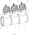
Fig. 2 shows an embodiment suitable for particular application cases and featuring a cuboid distribution manifold 1 (closed against gas inlet opening 2) having three cylindricalgas outlet nozzles 3 serially disposed in a linear manner, with onesmall valve 5 disposed on each, pointing in one direction. The cross-section of thedistribution manifold 1 can optionally be square, rectangular or also elliptical. -
Fig. 3 shows acylindrical distribution manifold 1 having a largegas inlet opening 2 with a circular cross-section and three serially disposedgas outlet nozzles 3 with onesmall valve 5 disposed on each, pointing in one direction. Thedistribution manifold 1 is closed against the gas inlet opening 2. If needed, a further small gas outlet nozzle with asmall valve 5 could be connected here. - In another possible embodiment according to
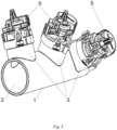
Fig. 4 , thedistribution manifold 1 according to the invention is of a modular construction, that means, it is assembled from several identically constructed modules. In at least one embodiment, there are three individual distribution manifold modules, the last of which is provided with a gastight closure on one side. If needed, more than three modules may be assembled into onedistribution manifold 1. The modules are cylindrical and disposed linearly, pointing in one direction. However, they may also be assembled circumferentially offset from each other such that thesmall valves 5 with theirgas outlet openings 4 point in different directions, in order to allow an optimal flow behaviour of the gas inside thegas meter 11. -
Fig. 5 again shows a one-piececylindrical distribution manifold 1 having three serially disposed, circumferentially offset cylindricalgas outlet nozzles 3 with onesmall valve 5 each, pointing in different directions. - Another arrangement of the
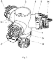
gas outlet nozzle 3 on the basic body ofdistribution manifold 1 is shown inFig. 6 . It shows acylindrical distribution manifold 1 having twogas outlet nozzles 3 disposed at an angle to each other on the same circumference and a thirdgas outlet nozzle 3 disposed axially in continuation to the inflow direction, with one small fittedvalve 5 each. However, three or more smallgas outlet nozzles 3 may be disposed on the circumference. -
Fig. 7 shows acylindrical distribution manifold 1 having threegas outlet nozzles 3 disposed in a star shape on the same circumference and a fourthgas outlet nozzle 3 disposed in axial continuation, each with an associatedsmall valve 5. This figure has a reference number forvalve cap 14, which is taken off infigure 8 . -
Fig. 8 shows a preferred embodiment of an actuatablesmall valve 5 which could be positioned ongas outlet nozzle 3, with novalve cap 14 fitted here. The size ofgas outlet opening 4 and thus the quantitative limitation of the laterally exiting gas flow is defined by the cross-section of the opening between the valve seat ofvalve body 6 and the valve seat of shut-offbody 7. This cross-section is smaller than in conventional larger gas shut-off valves. The spacing between the two valve seats is also smaller, so that, in parallel operation of thevalves 5, the gas flow can be interrupted faster than before because the travel paths for the flowoptimized, curved, mushroom-type shut-offbodies 7 are considerable smaller than with the previously used shut-off valves. - In at least one embodiment, the shut-off
body 7 is moved by means of a known nut-and-spindle drive 9. The nut-and-spindle drive 9 is driven by areduction gear 8. A small direct-current motor as a drive is installed in a separate housing chamber and disposed laterally beside the reduction gear unit. This separate housing chamber is integrally formed peripherally vertical such that the direct-current motor can be designed to be rotationally fixed, encapsulated and, if needed, spark protected. The electrical connections of the direct-current motor are guided out of the housing chamber. The motor shaft protrudes from the housing chamber and carries a motor pinion at the end to drive thereduction gear unit 8 of spur gears. This embodiment is constructively very small. - In at least one embodiment, each
valve 5 is designed such that it can be opened and closed by a shut-offbody 7 actuated by a motor-drivenreduction gear unit 8. Also, eachvalve 5 is individually electrically connected, driveable and actuatable. The essential advantage is that no electronic protection circuit is any longer needed due to the low electrical energy introduced into the explosive natural gas atmosphere (pervalve 5 always less than or equal to 320 µJ for natural gas). By two or moresmaller valves 5 being connected and operable in parallel, a higher total quantity of electrical energy can be introduced into the gas or explosive atmosphere because it is introduced in a quantized manner and each quantum on its own falls below the limit value. The sum of the individual electrical energies introduced through allvalves 5 into theindustrial gas meter 11 may therefore be larger than 320 µJ without any explosion hazard because each individual energy quantity per valve is definitely not sufficient to ignite the explosive atmosphere. The intrinsic safety of eachindividual valve 5 and of their associated electrical circuits is definitely ensured here. - The structure of the each
valve 5 on thegas outlet nozzle 3 is same. Eachvalve 5 could be actuated separately. In at least one embodiment, all thevalves 5 are respectively actuated, so that a same actuation circuit could be respectively connected to thevalve 5, thereby uniformly controlling the action of thevalves 5, so that thevalves 5 can be operated in parallel. Design and installation space of the actuation circuit with control function are not increased. - Preferably, the dimensions of the
gas outlet nozzles 3 are all equal. However, a special configuration of the distribution manifold is conceivable, where the dimensions of the individualgas outlet nozzles 3 are different. This demandssmall valves 5 of different appropriate sizes. Further, it is to be understood that, thesegas outlet nozzles 3 can be arbitrarily disposed depending on the available installation space of the respectiveindustrial gas meter 11. - Thanks to the many different embodiment variants of
gas outlet nozzles 3 disposed on the basic body of the distribution manifold (including a disposition at an obtuse angle relative to the symmetry axis of the distribution manifold) made possible by this solution according to the invention, it is possible to build industrial meters in a very compact design and also to realize favourable flow behaviours inside the industrial gas meters. - The technical solution described above is primarily usable as an innovative gas shut-off valve for constructively small industrial gas meters.
- The above embodiments are merely to illustrate the technical solutions of the present invention and are not intended to limit the present invention. Although the present invention has been described with reference to the above preferred embodiments, it should be appreciated by those skilled in the art that various modifications and variations may be made without departing from the scope of the present invention as defined by the appended claims.
Claims (11)
- A gas meter (11) comprising a distribution manifold (1) inside the gas meter (11), the distribution manifold (1) having:a gas inlet opening (2) of the gas meter;at least two smaller gas outlet nozzles (3);a valve (5) is disposed on each gas outlet nozzle (3);wherein each valve (5) is individually electrically connected and actuatable; characterized in that the gas meter (11) further comprisesa gas meter outlet (12) having a flow sensor (10) inside to measure and check flow volume.
- The gas meter (11) of claim 1, wherein each valve (5) is designed to be opened and closed by a shut-off body (7) actuated by a motor-driven reduction gear unit (8).
- The gas meter (11) of claim 1, wherein each valve (5) is actuated separately and simultaneously so that valves (5) are in parallel operation.
- The gas meter (11) of claim 1, wherein the distribution manifold (1) having at least two gas outlet nozzles (3) disposed on it is cuboid.
- The gas meter (11) of claim 1, wherein the distribution manifold (1) having at least two gas outlet nozzles (3) disposed on it is cylindrical.
- The gas meter (11) of claim 1, wherein the at least two gas outlet nozzles (3) are serially disposed on the distribution manifold (1) and pointed to one direction.
- The gas meter (11) of claim 1, wherein the at least two gas outlet nozzles (3) are disposed on the distribution manifold (1) in a radially distributed manner.
- The gas meter (11) of claim 1, wherein the at least two gas outlet nozzles (3) are disposed on the distribution manifold (1) at a right angle to a direction of gas inlet flow.
- The gas meter (11) of claim 1, wherein the distribution manifold (1) is a modular construction comprising several serially disposed individual distribution manifolds connected with each other in a gastight manner, each individual distribution manifold comprises a gas outlet nozzle (3).
- The gas meter (11) of claim 1, wherein a structure of each valve (5) on each gas outlet nozzle (3) is the same.
- The gas meter (11) of claim 1, wherein the valves (5) on the gas outlet nozzles (3) are connected in parallel to a same actuation circuit.
Applications Claiming Priority (1)
| Application Number | Priority Date | Filing Date | Title |
|---|---|---|---|
| DE102018129208.2A DE102018129208A1 (en) | 2018-11-20 | 2018-11-20 | Distribution element for a gas shut-off valve for installation in industrial gas meters |
Publications (2)
| Publication Number | Publication Date |
|---|---|
| EP3657140A1 EP3657140A1 (en) | 2020-05-27 |
| EP3657140B1 true EP3657140B1 (en) | 2023-03-01 |
Family
ID=68807982
Family Applications (1)
| Application Number | Title | Priority Date | Filing Date |
|---|---|---|---|
| EP19210422.2A Active EP3657140B1 (en) | 2018-11-20 | 2019-11-20 | Distribution manifold |
Country Status (3)
| Country | Link |
|---|---|
| EP (1) | EP3657140B1 (en) |
| CN (1) | CN212338279U (en) |
| DE (1) | DE102018129208A1 (en) |
Families Citing this family (1)
| Publication number | Priority date | Publication date | Assignee | Title |
|---|---|---|---|---|
| CN114459550A (en) * | 2022-01-12 | 2022-05-10 | 青岛乾程科技股份有限公司 | Novel ultrasonic gas meter and using method |
Family Cites Families (8)
| Publication number | Priority date | Publication date | Assignee | Title |
|---|---|---|---|---|
| US4984448A (en) * | 1989-11-16 | 1991-01-15 | Atmos Energy Corporation | Leak detector and utilization pressure manifold |
| DE29615677U1 (en) | 1996-09-09 | 1996-10-31 | Bm Controls A/S, Hedensted | Gas solenoid valve |
| GB0622554D0 (en) * | 2006-11-14 | 2006-12-20 | Delphi Tech Inc | Bypass assembly for a charge-air cooler |
| US20090114297A1 (en) * | 2007-11-02 | 2009-05-07 | Floyd Stanley Salser | Residential fire service fixture |
| US20120085434A1 (en) * | 2010-10-11 | 2012-04-12 | William Powanda | Method and apparatus for flow device |
| DE102013109891A1 (en) * | 2013-09-10 | 2015-03-12 | BorgWarner Esslingen GmbH | valve assembly |
| JP2017180612A (en) * | 2016-03-29 | 2017-10-05 | 岩谷産業株式会社 | Evaluation device for hydrogen gas dispenser, and vehicle |
| CN207961629U (en) * | 2018-02-12 | 2018-10-12 | 董服义 | Y types pair go out valve |
-
2018
- 2018-11-20 DE DE102018129208.2A patent/DE102018129208A1/en not_active Withdrawn
-
2019
- 2019-11-20 CN CN201922008180.9U patent/CN212338279U/en active Active
- 2019-11-20 EP EP19210422.2A patent/EP3657140B1/en active Active
Also Published As
| Publication number | Publication date |
|---|---|
| EP3657140A1 (en) | 2020-05-27 |
| CN212338279U (en) | 2021-01-12 |
| DE102018129208A1 (en) | 2020-05-20 |
Similar Documents
| Publication | Publication Date | Title |
|---|---|---|
| US8851443B2 (en) | Memory alloy-actuated apparatus and methods for making and using the same | |
| GB2514374A (en) | Electrically operated valve assembly | |
| EP2574796A1 (en) | Insert vaccuum pump | |
| US5178520A (en) | Double centrifugal pump with single casing and adapter insert | |
| KR102195270B1 (en) | Gas shut-off valve | |
| US8540206B2 (en) | Multi-stable actuation apparatus and methods for making and using the same | |
| DE112008003498B4 (en) | valve device | |
| EP3657140A1 (en) | Distribution manifold | |
| US20140123654A1 (en) | Fuel metering valve system | |
| DE102015109694B4 (en) | Shut-off valve for installation in gas meters and method of operating the same | |
| CN101351661A (en) | Adjusting drives with reduction gears for final control elements for air or liquid flow control | |
| US20070221278A1 (en) | Flow Interrupter for a Liquid or Gaseous Fluid Flow Pipe | |
| US7455073B2 (en) | Variable flow valve | |
| US10145560B2 (en) | Valve with integrated actuating device, notably for a combustion system | |
| US5094264A (en) | Electromechanical solenoid valve with ratchet system for positioning the coil assembly | |
| CN104455652A (en) | Unloading type electromagnetic valve | |
| US7806140B2 (en) | Power saving locking coil | |
| CN103790736A (en) | Valve device and manufacturing method for the same | |
| WO1995004892A1 (en) | Mixing and distributing valve apparatus | |
| US8727308B2 (en) | Adjustable electromagnetic fluid flow control valve | |
| US20110220215A1 (en) | Hydro-generator soft start | |
| EP1923644A2 (en) | Water boiler | |
| CN207298027U (en) | A kind of gases at high pressure special electromagnetic valve of suitable Width funtion | |
| US20070235079A1 (en) | Method and device for tapping a pipeline | |
| JPH07111653B2 (en) | Valve actuator |
Legal Events
| Date | Code | Title | Description |
|---|---|---|---|
| PUAI | Public reference made under article 153(3) epc to a published international application that has entered the european phase |
Free format text: ORIGINAL CODE: 0009012 |
|
| STAA | Information on the status of an ep patent application or granted ep patent |
Free format text: STATUS: THE APPLICATION HAS BEEN PUBLISHED |
|
| AK | Designated contracting states |
Kind code of ref document: A1 Designated state(s): AL AT BE BG CH CY CZ DE DK EE ES FI FR GB GR HR HU IE IS IT LI LT LU LV MC MK MT NL NO PL PT RO RS SE SI SK SM TR |
|
| AX | Request for extension of the european patent |
Extension state: BA ME |
|
| STAA | Information on the status of an ep patent application or granted ep patent |
Free format text: STATUS: REQUEST FOR EXAMINATION WAS MADE |
|
| 17P | Request for examination filed |
Effective date: 20201127 |
|
| RBV | Designated contracting states (corrected) |
Designated state(s): AL AT BE BG CH CY CZ DE DK EE ES FI FR GB GR HR HU IE IS IT LI LT LU LV MC MK MT NL NO PL PT RO RS SE SI SK SM TR |
|
| GRAP | Despatch of communication of intention to grant a patent |
Free format text: ORIGINAL CODE: EPIDOSNIGR1 |
|
| STAA | Information on the status of an ep patent application or granted ep patent |
Free format text: STATUS: GRANT OF PATENT IS INTENDED |
|
| INTG | Intention to grant announced |
Effective date: 20220602 |
|
| GRAJ | Information related to disapproval of communication of intention to grant by the applicant or resumption of examination proceedings by the epo deleted |
Free format text: ORIGINAL CODE: EPIDOSDIGR1 |
|
| STAA | Information on the status of an ep patent application or granted ep patent |
Free format text: STATUS: REQUEST FOR EXAMINATION WAS MADE |
|
| INTC | Intention to grant announced (deleted) | ||
| GRAP | Despatch of communication of intention to grant a patent |
Free format text: ORIGINAL CODE: EPIDOSNIGR1 |
|
| STAA | Information on the status of an ep patent application or granted ep patent |
Free format text: STATUS: GRANT OF PATENT IS INTENDED |
|
| INTG | Intention to grant announced |
Effective date: 20221116 |
|
| GRAS | Grant fee paid |
Free format text: ORIGINAL CODE: EPIDOSNIGR3 |
|
| GRAA | (expected) grant |
Free format text: ORIGINAL CODE: 0009210 |
|
| STAA | Information on the status of an ep patent application or granted ep patent |
Free format text: STATUS: THE PATENT HAS BEEN GRANTED |
|
| AK | Designated contracting states |
Kind code of ref document: B1 Designated state(s): AL AT BE BG CH CY CZ DE DK EE ES FI FR GB GR HR HU IE IS IT LI LT LU LV MC MK MT NL NO PL PT RO RS SE SI SK SM TR |
|
| REG | Reference to a national code |
Ref country code: GB Ref legal event code: FG4D |
|
| REG | Reference to a national code |
Ref country code: CH Ref legal event code: EP Ref country code: AT Ref legal event code: REF Ref document number: 1551264 Country of ref document: AT Kind code of ref document: T Effective date: 20230315 |
|
| REG | Reference to a national code |
Ref country code: DE Ref legal event code: R096 Ref document number: 602019025784 Country of ref document: DE |
|
| REG | Reference to a national code |
Ref country code: IE Ref legal event code: FG4D |
|
| REG | Reference to a national code |
Ref country code: LT Ref legal event code: MG9D |
|
| REG | Reference to a national code |
Ref country code: NL Ref legal event code: MP Effective date: 20230301 Ref country code: GB Ref legal event code: 746 Effective date: 20230612 |
|
| PG25 | Lapsed in a contracting state [announced via postgrant information from national office to epo] |
Ref country code: NO Free format text: LAPSE BECAUSE OF FAILURE TO SUBMIT A TRANSLATION OF THE DESCRIPTION OR TO PAY THE FEE WITHIN THE PRESCRIBED TIME-LIMIT Effective date: 20230601 Ref country code: LV Free format text: LAPSE BECAUSE OF FAILURE TO SUBMIT A TRANSLATION OF THE DESCRIPTION OR TO PAY THE FEE WITHIN THE PRESCRIBED TIME-LIMIT Effective date: 20230301 Ref country code: LT Free format text: LAPSE BECAUSE OF FAILURE TO SUBMIT A TRANSLATION OF THE DESCRIPTION OR TO PAY THE FEE WITHIN THE PRESCRIBED TIME-LIMIT Effective date: 20230301 Ref country code: HR Free format text: LAPSE BECAUSE OF FAILURE TO SUBMIT A TRANSLATION OF THE DESCRIPTION OR TO PAY THE FEE WITHIN THE PRESCRIBED TIME-LIMIT Effective date: 20230301 Ref country code: ES Free format text: LAPSE BECAUSE OF FAILURE TO SUBMIT A TRANSLATION OF THE DESCRIPTION OR TO PAY THE FEE WITHIN THE PRESCRIBED TIME-LIMIT Effective date: 20230301 Ref country code: RS Free format text: LAPSE BECAUSE OF FAILURE TO SUBMIT A TRANSLATION OF THE DESCRIPTION OR TO PAY THE FEE WITHIN THE PRESCRIBED TIME-LIMIT Effective date: 20230301 |
|
| P01 | Opt-out of the competence of the unified patent court (upc) registered |
Effective date: 20230628 |
|
| REG | Reference to a national code |
Ref country code: AT Ref legal event code: MK05 Ref document number: 1551264 Country of ref document: AT Kind code of ref document: T Effective date: 20230301 |
|
| PG25 | Lapsed in a contracting state [announced via postgrant information from national office to epo] |
Ref country code: SE Free format text: LAPSE BECAUSE OF FAILURE TO SUBMIT A TRANSLATION OF THE DESCRIPTION OR TO PAY THE FEE WITHIN THE PRESCRIBED TIME-LIMIT Effective date: 20230301 Ref country code: PL Free format text: LAPSE BECAUSE OF FAILURE TO SUBMIT A TRANSLATION OF THE DESCRIPTION OR TO PAY THE FEE WITHIN THE PRESCRIBED TIME-LIMIT Effective date: 20230301 Ref country code: NL Free format text: LAPSE BECAUSE OF FAILURE TO SUBMIT A TRANSLATION OF THE DESCRIPTION OR TO PAY THE FEE WITHIN THE PRESCRIBED TIME-LIMIT Effective date: 20230301 Ref country code: GR Free format text: LAPSE BECAUSE OF FAILURE TO SUBMIT A TRANSLATION OF THE DESCRIPTION OR TO PAY THE FEE WITHIN THE PRESCRIBED TIME-LIMIT Effective date: 20230602 Ref country code: FI Free format text: LAPSE BECAUSE OF FAILURE TO SUBMIT A TRANSLATION OF THE DESCRIPTION OR TO PAY THE FEE WITHIN THE PRESCRIBED TIME-LIMIT Effective date: 20230301 |
|
| PG25 | Lapsed in a contracting state [announced via postgrant information from national office to epo] |
Ref country code: SM Free format text: LAPSE BECAUSE OF FAILURE TO SUBMIT A TRANSLATION OF THE DESCRIPTION OR TO PAY THE FEE WITHIN THE PRESCRIBED TIME-LIMIT Effective date: 20230301 Ref country code: RO Free format text: LAPSE BECAUSE OF FAILURE TO SUBMIT A TRANSLATION OF THE DESCRIPTION OR TO PAY THE FEE WITHIN THE PRESCRIBED TIME-LIMIT Effective date: 20230301 Ref country code: PT Free format text: LAPSE BECAUSE OF FAILURE TO SUBMIT A TRANSLATION OF THE DESCRIPTION OR TO PAY THE FEE WITHIN THE PRESCRIBED TIME-LIMIT Effective date: 20230703 Ref country code: EE Free format text: LAPSE BECAUSE OF FAILURE TO SUBMIT A TRANSLATION OF THE DESCRIPTION OR TO PAY THE FEE WITHIN THE PRESCRIBED TIME-LIMIT Effective date: 20230301 Ref country code: CZ Free format text: LAPSE BECAUSE OF FAILURE TO SUBMIT A TRANSLATION OF THE DESCRIPTION OR TO PAY THE FEE WITHIN THE PRESCRIBED TIME-LIMIT Effective date: 20230301 Ref country code: AT Free format text: LAPSE BECAUSE OF FAILURE TO SUBMIT A TRANSLATION OF THE DESCRIPTION OR TO PAY THE FEE WITHIN THE PRESCRIBED TIME-LIMIT Effective date: 20230301 |
|
| PG25 | Lapsed in a contracting state [announced via postgrant information from national office to epo] |
Ref country code: SK Free format text: LAPSE BECAUSE OF FAILURE TO SUBMIT A TRANSLATION OF THE DESCRIPTION OR TO PAY THE FEE WITHIN THE PRESCRIBED TIME-LIMIT Effective date: 20230301 Ref country code: IS Free format text: LAPSE BECAUSE OF FAILURE TO SUBMIT A TRANSLATION OF THE DESCRIPTION OR TO PAY THE FEE WITHIN THE PRESCRIBED TIME-LIMIT Effective date: 20230701 |
|
| REG | Reference to a national code |
Ref country code: DE Ref legal event code: R097 Ref document number: 602019025784 Country of ref document: DE |
|
| PLBE | No opposition filed within time limit |
Free format text: ORIGINAL CODE: 0009261 |
|
| STAA | Information on the status of an ep patent application or granted ep patent |
Free format text: STATUS: NO OPPOSITION FILED WITHIN TIME LIMIT |
|
| PG25 | Lapsed in a contracting state [announced via postgrant information from national office to epo] |
Ref country code: SI Free format text: LAPSE BECAUSE OF FAILURE TO SUBMIT A TRANSLATION OF THE DESCRIPTION OR TO PAY THE FEE WITHIN THE PRESCRIBED TIME-LIMIT Effective date: 20230301 Ref country code: DK Free format text: LAPSE BECAUSE OF FAILURE TO SUBMIT A TRANSLATION OF THE DESCRIPTION OR TO PAY THE FEE WITHIN THE PRESCRIBED TIME-LIMIT Effective date: 20230301 |
|
| 26N | No opposition filed |
Effective date: 20231204 |
|
| REG | Reference to a national code |
Ref country code: DE Ref legal event code: R119 Ref document number: 602019025784 Country of ref document: DE |
|
| REG | Reference to a national code |
Ref country code: CH Ref legal event code: PL |
|
| PG25 | Lapsed in a contracting state [announced via postgrant information from national office to epo] |
Ref country code: MC Free format text: LAPSE BECAUSE OF FAILURE TO SUBMIT A TRANSLATION OF THE DESCRIPTION OR TO PAY THE FEE WITHIN THE PRESCRIBED TIME-LIMIT Effective date: 20230301 |
|
| PG25 | Lapsed in a contracting state [announced via postgrant information from national office to epo] |
Ref country code: LU Free format text: LAPSE BECAUSE OF NON-PAYMENT OF DUE FEES Effective date: 20231120 |
|
| PG25 | Lapsed in a contracting state [announced via postgrant information from national office to epo] |
Ref country code: CH Free format text: LAPSE BECAUSE OF NON-PAYMENT OF DUE FEES Effective date: 20231130 |
|
| PG25 | Lapsed in a contracting state [announced via postgrant information from national office to epo] |
Ref country code: MC Free format text: LAPSE BECAUSE OF FAILURE TO SUBMIT A TRANSLATION OF THE DESCRIPTION OR TO PAY THE FEE WITHIN THE PRESCRIBED TIME-LIMIT Effective date: 20230301 Ref country code: LU Free format text: LAPSE BECAUSE OF NON-PAYMENT OF DUE FEES Effective date: 20231120 Ref country code: CH Free format text: LAPSE BECAUSE OF NON-PAYMENT OF DUE FEES Effective date: 20231130 |
|
| REG | Reference to a national code |
Ref country code: BE Ref legal event code: MM Effective date: 20231130 |
|
| REG | Reference to a national code |
Ref country code: IE Ref legal event code: MM4A |
|
| PG25 | Lapsed in a contracting state [announced via postgrant information from national office to epo] |
Ref country code: DE Free format text: LAPSE BECAUSE OF NON-PAYMENT OF DUE FEES Effective date: 20240601 Ref country code: IE Free format text: LAPSE BECAUSE OF NON-PAYMENT OF DUE FEES Effective date: 20231120 |
|
| PG25 | Lapsed in a contracting state [announced via postgrant information from national office to epo] |
Ref country code: BE Free format text: LAPSE BECAUSE OF NON-PAYMENT OF DUE FEES Effective date: 20231130 |
|
| PG25 | Lapsed in a contracting state [announced via postgrant information from national office to epo] |
Ref country code: FR Free format text: LAPSE BECAUSE OF NON-PAYMENT OF DUE FEES Effective date: 20231130 |
|
| PG25 | Lapsed in a contracting state [announced via postgrant information from national office to epo] |
Ref country code: IE Free format text: LAPSE BECAUSE OF NON-PAYMENT OF DUE FEES Effective date: 20231120 Ref country code: FR Free format text: LAPSE BECAUSE OF NON-PAYMENT OF DUE FEES Effective date: 20231130 Ref country code: DE Free format text: LAPSE BECAUSE OF NON-PAYMENT OF DUE FEES Effective date: 20240601 Ref country code: BE Free format text: LAPSE BECAUSE OF NON-PAYMENT OF DUE FEES Effective date: 20231130 |
|
| PG25 | Lapsed in a contracting state [announced via postgrant information from national office to epo] |
Ref country code: BG Free format text: LAPSE BECAUSE OF FAILURE TO SUBMIT A TRANSLATION OF THE DESCRIPTION OR TO PAY THE FEE WITHIN THE PRESCRIBED TIME-LIMIT Effective date: 20230301 |
|
| PG25 | Lapsed in a contracting state [announced via postgrant information from national office to epo] |
Ref country code: BG Free format text: LAPSE BECAUSE OF FAILURE TO SUBMIT A TRANSLATION OF THE DESCRIPTION OR TO PAY THE FEE WITHIN THE PRESCRIBED TIME-LIMIT Effective date: 20230301 |
|
| PG25 | Lapsed in a contracting state [announced via postgrant information from national office to epo] |
Ref country code: CY Free format text: LAPSE BECAUSE OF FAILURE TO SUBMIT A TRANSLATION OF THE DESCRIPTION OR TO PAY THE FEE WITHIN THE PRESCRIBED TIME-LIMIT; INVALID AB INITIO Effective date: 20191120 |
|
| PG25 | Lapsed in a contracting state [announced via postgrant information from national office to epo] |
Ref country code: HU Free format text: LAPSE BECAUSE OF FAILURE TO SUBMIT A TRANSLATION OF THE DESCRIPTION OR TO PAY THE FEE WITHIN THE PRESCRIBED TIME-LIMIT; INVALID AB INITIO Effective date: 20191120 |
|
| PGFP | Annual fee paid to national office [announced via postgrant information from national office to epo] |
Ref country code: GB Payment date: 20251125 Year of fee payment: 7 |
|
| PGFP | Annual fee paid to national office [announced via postgrant information from national office to epo] |
Ref country code: IT Payment date: 20251121 Year of fee payment: 7 |
|
| PGFP | Annual fee paid to national office [announced via postgrant information from national office to epo] |
Ref country code: TR Payment date: 20251106 Year of fee payment: 7 |