EP3657083A1 - Filter, manufacturing method for filter and air conditioner - Google Patents
Filter, manufacturing method for filter and air conditioner Download PDFInfo
- Publication number
- EP3657083A1 EP3657083A1 EP18924370.2A EP18924370A EP3657083A1 EP 3657083 A1 EP3657083 A1 EP 3657083A1 EP 18924370 A EP18924370 A EP 18924370A EP 3657083 A1 EP3657083 A1 EP 3657083A1
- Authority
- EP
- European Patent Office
- Prior art keywords
- casing
- filter screen
- wall
- filter
- section
- Prior art date
- Legal status (The legal status is an assumption and is not a legal conclusion. Google has not performed a legal analysis and makes no representation as to the accuracy of the status listed.)
- Granted
Links
Images




Classifications
-
- F—MECHANICAL ENGINEERING; LIGHTING; HEATING; WEAPONS; BLASTING
- F24—HEATING; RANGES; VENTILATING
- F24F—AIR-CONDITIONING; AIR-HUMIDIFICATION; VENTILATION; USE OF AIR CURRENTS FOR SCREENING
- F24F13/00—Details common to, or for air-conditioning, air-humidification, ventilation or use of air currents for screening
- F24F13/28—Arrangement or mounting of filters
-
- B—PERFORMING OPERATIONS; TRANSPORTING
- B01—PHYSICAL OR CHEMICAL PROCESSES OR APPARATUS IN GENERAL
- B01D—SEPARATION
- B01D46/00—Filters or filtering processes specially modified for separating dispersed particles from gases or vapours
- B01D46/0002—Casings; Housings; Frame constructions
- B01D46/0005—Mounting of filtering elements within casings, housings or frames
-
- B—PERFORMING OPERATIONS; TRANSPORTING
- B01—PHYSICAL OR CHEMICAL PROCESSES OR APPARATUS IN GENERAL
- B01D—SEPARATION
- B01D46/00—Filters or filtering processes specially modified for separating dispersed particles from gases or vapours
- B01D46/24—Particle separators, e.g. dust precipitators, using rigid hollow filter bodies
- B01D46/2403—Particle separators, e.g. dust precipitators, using rigid hollow filter bodies characterised by the physical shape or structure of the filtering element
- B01D46/2411—Filter cartridges
-
- F—MECHANICAL ENGINEERING; LIGHTING; HEATING; WEAPONS; BLASTING
- F24—HEATING; RANGES; VENTILATING
- F24F—AIR-CONDITIONING; AIR-HUMIDIFICATION; VENTILATION; USE OF AIR CURRENTS FOR SCREENING
- F24F13/00—Details common to, or for air-conditioning, air-humidification, ventilation or use of air currents for screening
- F24F13/02—Ducting arrangements
- F24F13/0209—Ducting arrangements characterised by their connecting means, e.g. flanges
-
- F—MECHANICAL ENGINEERING; LIGHTING; HEATING; WEAPONS; BLASTING
- F24—HEATING; RANGES; VENTILATING
- F24F—AIR-CONDITIONING; AIR-HUMIDIFICATION; VENTILATION; USE OF AIR CURRENTS FOR SCREENING
- F24F13/00—Details common to, or for air-conditioning, air-humidification, ventilation or use of air currents for screening
- F24F13/02—Ducting arrangements
- F24F13/0254—Ducting arrangements characterised by their mounting means, e.g. supports
-
- F—MECHANICAL ENGINEERING; LIGHTING; HEATING; WEAPONS; BLASTING
- F24—HEATING; RANGES; VENTILATING
- F24F—AIR-CONDITIONING; AIR-HUMIDIFICATION; VENTILATION; USE OF AIR CURRENTS FOR SCREENING
- F24F13/00—Details common to, or for air-conditioning, air-humidification, ventilation or use of air currents for screening
- F24F13/20—Casings or covers
-
- F—MECHANICAL ENGINEERING; LIGHTING; HEATING; WEAPONS; BLASTING
- F24—HEATING; RANGES; VENTILATING
- F24F—AIR-CONDITIONING; AIR-HUMIDIFICATION; VENTILATION; USE OF AIR CURRENTS FOR SCREENING
- F24F8/00—Treatment, e.g. purification, of air supplied to human living or working spaces otherwise than by heating, cooling, humidifying or drying
- F24F8/10—Treatment, e.g. purification, of air supplied to human living or working spaces otherwise than by heating, cooling, humidifying or drying by separation, e.g. by filtering
-
- B—PERFORMING OPERATIONS; TRANSPORTING
- B01—PHYSICAL OR CHEMICAL PROCESSES OR APPARATUS IN GENERAL
- B01D—SEPARATION
- B01D2279/00—Filters adapted for separating dispersed particles from gases or vapours specially modified for specific uses
- B01D2279/50—Filters adapted for separating dispersed particles from gases or vapours specially modified for specific uses for air conditioning
-
- B—PERFORMING OPERATIONS; TRANSPORTING
- B23—MACHINE TOOLS; METAL-WORKING NOT OTHERWISE PROVIDED FOR
- B23K—SOLDERING OR UNSOLDERING; WELDING; CLADDING OR PLATING BY SOLDERING OR WELDING; CUTTING BY APPLYING HEAT LOCALLY, e.g. FLAME CUTTING; WORKING BY LASER BEAM
- B23K11/00—Resistance welding; Severing by resistance heating
- B23K11/10—Spot welding; Stitch welding
- B23K11/11—Spot welding
-
- B—PERFORMING OPERATIONS; TRANSPORTING
- B23—MACHINE TOOLS; METAL-WORKING NOT OTHERWISE PROVIDED FOR
- B23K—SOLDERING OR UNSOLDERING; WELDING; CLADDING OR PLATING BY SOLDERING OR WELDING; CUTTING BY APPLYING HEAT LOCALLY, e.g. FLAME CUTTING; WORKING BY LASER BEAM
- B23K2103/00—Materials to be soldered, welded or cut
- B23K2103/02—Iron or ferrous alloys
- B23K2103/04—Steel or steel alloys
- B23K2103/05—Stainless steel
-
- B—PERFORMING OPERATIONS; TRANSPORTING
- B23—MACHINE TOOLS; METAL-WORKING NOT OTHERWISE PROVIDED FOR
- B23K—SOLDERING OR UNSOLDERING; WELDING; CLADDING OR PLATING BY SOLDERING OR WELDING; CUTTING BY APPLYING HEAT LOCALLY, e.g. FLAME CUTTING; WORKING BY LASER BEAM
- B23K2103/00—Materials to be soldered, welded or cut
- B23K2103/08—Non-ferrous metals or alloys
- B23K2103/12—Copper or alloys thereof
Definitions
- the present disclosure relates to the technical field of air conditioning equipment, and more particularly, to a filter, a manufacturing method for a filter, and an air conditioner.
- a conventional filter for an air conditioner mainly has a structure of carbon steel, which means a casing of the filter is assembled by carbon steel, and the casing is welded to a transition tube, resulting in tedious machining processes.
- the casing generally needs coating on its surface due to that carbon steel material is easy to rust. There are strict requirement of powers for spraying operations, resulting in tedious steps of the processes and affecting the production efficiency of filters.
- the casing is welded to the transition tube at a very low temperature, the coating on the casing is easy to burn out when the filter is welded to an external copper tube in the later period, resulting in risks of leakage between the casing and the transition tube.
- the conventional filter has a short casing, resulting in small area of a filter screen in the casing and poor filtering effect.
- the conventional filter for an air conditioner generally comprises the casing and a filter screen assembly arranged in the casing.
- the filter screen assembly is in the shape of a funnel, a metal support is usually added in an inner surface of the funnel filter screen in order to enhance the strength of the funnel filter screen. Since the added metal support is an integrally formed cross, raw materials are wasted due to this kind of design.
- the tensile length is generally limited because the material is limited by extendability, resulting in an over-small effective filtering area of the filter screen assembly, furthering causing that the filtering effect of the filter screen assembly become poor.
- the present disclosure seeks to solve at least one of the problems existing in the related art to at least some extent.
- an objective of the present disclosure is to provide a filter.
- Another objective of the present disclosure is to provide a manufacturing method for a filter.
- Still another objective of the present disclosure is to provide an air conditioner.
- a filter according to embodiments of a first aspect includes: a casing; a transition tube; and a filter screen assembly provided in the casing, fitted with and connected to an inner wall of the casing, the casing being an integrally formed piece, each of two axial ends of the casing has a neck section, and the two neck sections being fixedly connected to the transition tube.
- the casing is the integrally formed piece, splicing process is needless, on the premise that the strength and filtering effects of the filter are satisfied, steps for manufacturing the casing can be simplified, and the production efficiency of the casing can be raised.
- the neck section includes a tapered section having a gradually reduced diameter and a straight tube section, the straight tube section is connected to the tapered section and arranged in an axial direction, and the transition tube is fixedly connected to the straight tube section.
- the transition tube is fixed to the straight tube section by welding.
- the transition tube is embedded into the straight tube section, and an outer wall of the transition tube in contact with the straight tube section is provided with drawing lines.
- an outer end of the transition tube is flush with an end of the straight tube section.
- an outer end of the transition tube extends out of the straight tube section and forms a connecting section.
- an outer end of the transition tube extends out of the straight tube section and forms a covering section, the covering section abuts against an end of the straight tube section, and an outer wall of the covering section is flush with an outer wall of the straight tube section.
- the filter screen assembly is fixed to the inner wall of the casing by welding.
- At least one annular groove sunken towards the inner wall of the casing is defined on an outer wall of the casing by punching, the inner wall of the casing is provided with an annular protrusion protruding out at a position corresponding to the annular groove, and the filter screen assembly is connected to the annular protrusion by snapping.
- the casing is integrally formed from stainless steel or copper.
- the filter screen assembly includes a cylindrical filter screen, an outer fixing ring, an inner fixing ring and a support; the inner fixing ring is fixedly connected into the outer fixing ring, the cylindrical filter screen has an opening, a circumferential edge of the opening is interposed between the inner fixing ring and the outer fixing ring; the support includes at least one U-shaped support strip, each U-shaped support strip extends into the cylindrical filter screen through the opening and supports the cylindrical filter screen, and two tail ends of each U-shaped support strip are both fixedly connected to the inner fixing ring.
- each U-shaped support strip is both bent into edgefolds, and the edgefold abut against the inner fixing ring and are fixed to the inner fixing ring by spot welding.
- more than two U-shaped support strips are provided, and bottoms of adjacent two U-shaped support strips are fixed by spot welding.
- U-shaped support strips are provided, and the U-shaped support strips uniformly cross each other at midpoints of bottoms thereof.
- an upper surface and a lower surface of a bottom of each U-shaped support strip are provided with an inner recess and an outer protrusion respectively, and positions of the inner recess and the outer protrusion correspond to each other, adjacent two U-shaped support strips are positioned by means of cooperation between the inner recess and the outer protrusion; or an upper surface and a lower surface of a bottom of each U-shaped support strip are provided with an outer protrusion and an inner recess respectively, and positions of the outer protrusion and the inner recess correspond to each other, adjacent two U-shaped support strip are positioned by means of cooperation between the inner recess and the outer protrusion.
- the circumferential edge of the opening is bent into an annular body in a radial direction, and the annular body is interposed between the inner fixing ring and the outer fixing ring.
- the cylindrical filter screen has a conical or cylindrical vertical section.
- the outer fixing ring includes an outer bottom ring body and an outer side ring body, and the outer side ring body is connected to a circumferential edge of the outer bottom ring body and extending in an axial direction
- the inner fixing ring includes an inner bottom ring body and an inner side ring body, and the inner side ring body is connected to a circumferential edge of the inner bottom ring body and extends in the radial direction; and the inner side ring body abuts against an inner surface of the outer side ring body, the inner bottom ring body abuts against an upper surface of the outer bottom ring body and is fixed to the outer bottom ring body by spot welding, and the circumferential edge of the opening is interposed between the inner bottom ring body and the outer bottom ring body.
- a manufacturing method for a filter according to embodiments of a second aspect includes: providing a material free of spraying and integrally forming a casing from the material free of spraying at S01; necking a first axial end of the casing to form a neck section at S02; providing a filter screen assembly, pressing the filter screen assembly in through a second axial end of the casing and enabling the filter screen assembly to be fitted with and connected to an inner wall of the casing at S03; necking the second axial end of the casing to form another neck section at S04; and connecting a transition tube to the neck section at each of the two axial ends of the casing respectively at S05.
- the manufacturing method for a filter according to embodiments of the present disclosure is simple in steps and high in production efficiency.
- the filter screen assembly is fixed to an inner wall of the casing by welding.
- At S03 at least one annular groove sunken towards the inner wall of the casing is defined on an outer wall of the casing by punching, such that the inner wall of the casing protrudes to form an annular protrusion with the annular groove, and the filter screen assembly is connected to the annular protrusion by snapping.
- a first annular groove sunken towards the inner wall of the casing is defined on the outer wall of the casing by punching, such that the inner wall of the casing protrudes to form a first annular protrusion, when the filter screen assembly is pressed into the casing, an end of the filter screen assembly is flush with the first annular protrusion
- a second annular groove sunken towards the inner wall of the casing is defined on the outer wall of the casing by punching, such that the inner wall of the casing protrudes to form a second annular protrusion with the another annular groove, and the first and the second annular protrusions hold the end of the filter screen assembly.
- material free of spraying is stainless steel or copper.
- the transition tube is fixed to the neck section by spot welding.
- the transition tube is welded to the neck section at a temperature higher than 810 °C.
- the air conditioner to embodiments of the present disclosure is provided with the above filter, the production efficiency of the filter of the air conditioner can be raised.
- first and second are used herein for purposes of description and are not intended to indicate or imply relative importance or significance or to imply the number of indicated technical features.
- the feature defined with “first” and “second” may comprise one or more of this feature.
- the term “a plurality of” means two or more than two, unless specified otherwise.
- the terms “mounted,” “connected,” “coupled,” “fixed” and the like are used broadly, and may be, for example, fixed connections, detachable connections, or integral connections; may also be mechanical or electrical connections; may also be direct connections or indirect connections via intervening structures; may also be inner communications of two elements, which can be understood by those skilled in the art according to specific situations.
- a filter provided by embodiments of the present disclosure is mainly used in an air conditioner and for connecting a refrigerant tube 40.
- the filter includes a casing 10, a transition tube 20 and a filter screen assembly 30.
- the filter screen assembly 30 is arranged in the casing 10 and is fitted with and connected to an inner wall of the casing 10. That the filter screen assembly 30 is fitted with and connected to the inner wall of the casing 10 refers to non-detachable connection or detachable connection.
- the casing 10 is an integrally formed piece. Since the casing 10 is the integrally formed piece, integrally formed manufacturing can be achieved instead of splicing structures of carbon steel.
- the integrally formed piece can be made of other new material, preferably stainless steel or copper, free of spraying other than structures of carbon steel, thereby improving corrosion resistant performance of the casing 10.
- each of two axial ends of the casing 10 has a neck section 11.
- neck sections 11 at two axial ends of the casing 10 comparatively small joints can be formed at the two axial ends of the casing 10, such that sizes of the two neck sections 11 matches sizes of a mouth of the transition tube 20, and the casing 10 is easy to fixedly connected to the transition tube 20.
- the casing 10 is the integrally formed piece, splicing process is needless, on the premise that the strength and filtering effects of the filter are satisfied, steps for manufacturing the casing 10 can be simplified, and the production efficiency of the casing 10 can be raised.
- the integrally formed piece can be made of new materials besides structures of carbon steel, it is needless to add a coating on an outer surface of the casing 10, corrosion resistance is no longer good, and a process for spraying is saved, thereby raising the production efficiency of the filter.
- an axial end of the casing 1 is necked, and then the neck section 11 is formed at the end; the other axial end of the filter screen assembly 30 which is not been necked yet is pressed into the casing 10, and the filter screen assembly 30 is fixedly connected to the inner wall of the casing 10; and finally the other axial end of the filter screen assembly 30 which is not necked yet is necked, and transition tubes 20 are fixedly connected to the two neck sections 11. With the transition tube 20, the filter can be conveniently connected to the refrigerant tube 40.
- the neck section 11 comprises a tapered section 111 having a gradually reduced diameter and a straight tube section 112.
- the straight tube section 112 is connected to the tapered section 111 and arranged in an axial direction.
- the transition tube 20 is fixedly connected to the straight tube section 112.
- the tapered section 111 having the gradually reduced diameter can make the casing 10 have gradually reduced spaces adjacent to the two axial ends thereof, which effectively prevents the filter screen assembly 30 fixed in the casing 10 from falling out from two ends of the casing 10.
- the casing 10 transmit from the tapered section 111 to the straight tube section 112 smoothly, and can be adapt to be connected to the transition tube 20 via the straight tube section 112. Since the transition tube 20 is comparatively small, an auxiliary adaptor can be saved by means of the straight tube section 112, the transition tube 20 can be fixedly connected to the casing 10 via connection between the straight tube section 112 and the transition tube 20.
- a preferable manner for fixedly connected the transition tube 20 to the straight tube section 112 is welding.
- the transition tube 20 is fixed to the straight tube section 112 by welding can ensure good and stable connection and durable performance.
- the welding process is simple and easy to operate, the transition tube 20 and the straight tube section 112 can be quickly assembled during manufacturing with high production efficiency.
- the transition tube 20 is welded to the straight tube section 112 at a temperature higher than 810 °C, since the straight tube section 112 is a part of the casing 10, the welding temperature is higher than 810 °C during welding operation on the transition tube 20 and the casing 10, such that the transition tube 20 is fixed at a high temperature, and the welding temperature is much lower than 810 °C when the filter is welded to the refrigerant tube 40 in the latter.
- the temperature at which the refrigerant tube 40 is welded does not affect stability of the welding position between the transition tube 20 and the casing 10, such that risks of leakage between the casing 10 and the transition tube 20 due to welding the refrigerant tube 40 can be effectively avoided.
- the transition tube 20 is embedded in to the straight tube section 112, and the transition tube 20 is provided with drawing lines 21 at an outer wall in contact with the straight tube section 112. That means the outer wall of a part of the transition tube 20 embedded into the straight tube section 112 is provided with the drawing lines 21, and the drawing lines 21 can be formed by wire drawing process.
- a welding flux can be well arranged through the drawing lines 21 on the transition tube 20, the welding flux and a contact area between the straight tube section 112 and the transition tube 20 can be increased, stability and reliability of the transition tube 20 and the straight tube section 112 can be greatly improved after the are fixed by welding.
- a first structure for the transition tube 20 is that an outer end of the transition tube 20 is flush with an end of the straight tube section 112. Specifically, the transition tube 20 of this structure is entirely embedded into the straight tube section 112 and fixed to the straight tube section 112 by welding. In such manner, in the condition that the filter has a constant total length, the casing 10 can be designed longer, that means the length of the casing 10 is enlarged, such that the filter screen assembly 30 provided in the casing 10 can be designed to have a larger size, then the filter screen assembly 30 has an increased effective filtering area, and the filtering quality is improved.
- a second structure for the transition tube 20 is that and outer end of the transition tube 20 extends out of the straight tube section 112 and forms a connecting section 22.
- the transition tube 20 of this structure has a connecting section 22 extending out of the straight tube section 112 at a certain distance, and the connecting section 22 can be used to connect the refrigerant tube 40.
- An size of the connecting section 22 can be designed as an optimized size to adapt to connection with the refrigerant tube 40, which is convenient to mount and will not be affected by a size of the straight tube section 112.
- a third structure for the transition tube 20 is that an outer of the transition tube 20 extends out of the straight tube section 112 and forms a covering section 23, the covering section 23 abuts against an end of the straight tube section 112, and an outer wall of the covering section 23 is flush with an outer wall of the straight tube section 11.
- the transition tube 20 of this structure has the covering section 23 used to cover the end of the straight tube section 112, the end of the straight tube section 112 can be isolated by the covering section 23, in such manner, the welding flux can be prevented from contacting the straight tube section 112 when the transition tube 20 is welded to the refrigerant tube 40, which raises the welding quality.
- the filter screen assembly 30 can be fixedly connected to the inner of the casing 10 at least by the two manners as follows.
- the filter screen assembly 30 is fixed to the inner wall of the casing 10 by welding. Because the filter screen assembly 30 is fixed to the inner wall of the casing 10 by welding, it can be ensured that the fixation of the filter screen assembly 30 on the inner wall of is stable and reliable, and the filter screen assembly 30 is not easy to fall off after fixation.
- annular groove 12 sunken towards the inner wall of the casing 10 is defined on the outer wall of the casing 10 by punching.
- the inner wall of the casing 10 is provided with an annular protrusion 13 protruding out at a position corresponding to the annular groove 12.
- the filter screen assembly 30 is connected to the annular protrusion 13 by snapping.
- the annular groove 12 is defined on the outer wall of the casing 10 by punching, such that the annular groove 12 is sunken to form the annular protrusion 13 in the casing 10.
- annular protrusion 13 can also serves for positioning and mounting, the annular groove 12 can play a role of limiting and indicating a mounting position of the filter screen assembly 30.
- the number of the annular groove 12 can be set as two, or there, or more than three according to actual needs, similarly, two, or three, or more than three annular protrusions 13 are formed.
- a filter screen assembly 30 provided by embodiments of the present disclosure comprises a cylindrical filter screen 3010, an outer fixing ring 3020, an inner fixing ring 3030 and a support 3040.
- the inner fixing ring 3030 is fixedly connected in the outer fixing ring 3020, and the inner fixing ring 3030 can be connected to the outer fixing ring 3020 by embedding or welding.
- the inner fixing ring 3030 is used to clamp and fix the cylindrical filter screen 3010
- the inner fixing ring 3030 is used to connected to the support 3040.
- the cylindrical filter screen 3010 has an opening 3011, a circumferential edge of the opening 3011 is interposed between the inner fixing ring 3030 and the outer fixing ring 3020.
- the support 3040 comprises at least one U-shaped support strip 3041, each U-shaped support strip 3041 and extends into the cylindrical filter screen 3010 through the opening 3011 and supports the cylindrical filter screen 3010, and two tail ends of each U-shaped support strip 3041 are both fixedly connected to the inner fixing ring 3030, the cylindrical filter screen 3010 is fixed by the inner fixing ring 3030 and the outer fixing ring 3020, and is supported by the support 3040 to be kept in a cylindrical state, to effectively show its filtering effect.
- the number of the U-shaped support strip 3041 can be set according to actual needs. As shown in FIGS. 10 to 11 , may be one, or two, or three, or more than three U-shaped support strips are provided for example. In addition, each U-shaped support strip 3041 is used for supporting separately. If more than two U-shaped support strips 3041 are provided, the U-shaped support strips are assembled and connected after each single U-shaped support strip 3041 is manufactured, there is no need to integrally form the support 3040, material waste can be reduced to the minimum. At the meantime, length elongation can be implemented during manufacturing due to the single U-shaped support strip 3041 has a small structure.
- the support 3040 formed in this manner can have a longer length, correspondingly, the cylindrical filter screen 3010 can be designed to have a longer length, and the cylindrical filter screen 3010 is lager in effective filtering area.
- each single U-shaped support strip 3041 can be manufactured separately. In such manner, not only material waste caused by that the support 3040 is integrally formed can be reduced. In the meantime, length elongation can be implemented during manufacturing due to the single U-shaped support strip 3041 has an elongated structure.
- the support 3040 manufactured by the U-shaped support strip 3041 can have a longer length, the cylindrical filter screen 3010 can be designed to have a larger size, and the cylindrical filter screen 3010 which can be supported by the support 3040 is lager in effective filtering area, thereby the filtering effect of the filter screen assembly 30 can be greatly improved.
- two tail end of each U-shaped support strip 3041 are both bent into edgefolds 30411, and the edgefolds 30411 abut against the inner fixing ring 3030 and are fixed to the inner fixing ring 3030 by spot welding.
- the edgefolds 30411 can abut against the inner fixing ring 3030, one the one hand positioning is achieved, and one the other hand the contact area between the edgefolds and the inner fixing ring 3030 can be increased.
- the edgefold 30411 is fixed to the inner fixing ring 3030 by once-through spot welding, the connection is good in stability.
- more than two U-shaped support strips 3041 are provided, and bottoms of adjacent two U-shaped support strips 3041 are fixed by spot welding.
- two adjacent (upper and down) support stripes are fixed together by once-through spot welding, the operation is simple and convenient, and the connection is good in stability.
- U-shaped support strips 3041 are provided, the U-shaped support strips 3041 uniformly cross each other at midpoints of bottoms thereof. With such design, the U-shaped support strips 3041 of the support 3040 are uniformly and radially distributed about a center, i.e. the midpoints of the bottoms. After the support supports the cylindrical filter screen 3010 in this manner, the cylindrical filter screen 3010 can be supported at positions with uniform force.
- each U-shaped support strip 3041 are provided with an inner recess 30412 and an outer protrusion 30413 respectively, and positions of the inner recess 30412 and the outer protrusion 30413 correspond to each other, adjacent two U-shaped support strips 3041 are positioned by means of cooperation between the inner recess 30412 and the outer protrusion 30413.
- each U-shaped support strip 3041 is provided with an outer protrusion 30413 and an inner recess 30412 respectively, and positions of the outer protrusion 30413 and the inner recess 30412 correspond to each other, adjacent two U-shaped support strip 3041 are positioned by means of cooperation between the inner recess 30412 and the outer protrusion 30413.
- a circumferential edge of the opening 3011 is bent into an annular body 3012 in a radial direction, the annular body 3012 is interposed between the inner fixing ring 3030 and the outer fixing ring 3020.
- the inner fixing ring 3030 and the outer fixing ring 3020 tightly press the annular body 3012 after the inner fixing ring 3030 and the outer fixing ring 3020 are fixedly connected together by spot welding, such that the cylindrical filter screen 3010 is fixed.
- the annular body 3012 is a part of the cylindrical filter screen 3010, the annular body 3012 is bent in a radial direction at a circumferential edge of the opening 3011 to include an angle about 90 degrees together with the cylindrical filter screen 3010.
- the cylindrical filter screen 3010 has a conical or cylindrical vertical section.
- An inner diameter of the opening 3011 of the cylindrical filter screen 3010 is greater than or equal to an inner diameter of another end opposite the opening 3011 of the cylindrical filter screen 3010.
- the outer fixing ring 3020 comprises an outer bottom ring body 3021 and an outer side ring body 3022, the outer side ring body 3022 is connected to a circumferential edge of the outer bottom ring body 3021 and extends in a radial direction.
- the outer side ring body 3022 and the outer bottom ring body 3021 are integrally formed as the outer fixing ring 3020.
- the inner fixing ring 3030 comprises an inner bottom ring body 3031 and an inner side ring body 3032, and the inner side ring body 3032 is connected to a circumferential edge of the inner bottom ring body 3031 and extends in the radial direction.
- the inner side ring body 3032 and the inner bottom ring body 3031 are integrally formed as the inner fixing ring 3030.
- the inner side ring body 3032 abuts against an inner surface of the outer side ring body 3022, the inner side ring body 3032 is fitted with the outer side ring body 3022 to limit each other to achieve positioning.
- the inner bottom ring body 3031 abuts against an upper surface of the outer bottom ring body 3021 and is fixed to the outer bottom ring body 3021 by spot welding. A plurality of spot welding points are distributed in an annular manner, and the inner bottom ring body 3031 is fixed to the outer bottom ring body 3021 by spot welding. On the one hand, operation is easy, and on the other hand, connection can be ensured to be good in stability.
- the circumferential edge of the opening 3011 is interposed between the inner bottom ring body 3031 and the outer bottom ring body 3021.
- the annular body 3012 provided on the circumferential edge of the opening 3011 is interposed between the inner bottom ring body 3031 and the outer bottom ring body 3021, the annular body 3012 is fixed by clamping force generated by the welded the inner bottom ring body 3031 and the outer bottom ring body 3021, and the cylindrical filter screen 3010 is fixed in such manner.
- the filter of embodiments of the present disclosure is provided with the filter screen assembly 30 described above, because the support 3040 can be manufactured to have a longer length without increase in cost, correspondingly the cylindrical filter screen 3010 can be designed to have a larger size, such that the filter screen assembly 30 has a better filtering effect and the filter is better in filtering.
- this embodiment provides a manufacturing method for a filter.
- the manufacturing method comprises the following steps.
- a material free of spraying is provided, and a casing 10 is integrally formed from the material free of spraying.
- a first axial end of the casing 10 is necked to form a neck section 11.
- a filter screen assembly 30 is provided, the filter screen assembly 30 is pressed in through a second axial end of the casing 10 and fitted with and connected to an inner wall of the casing 10.
- the second axial end of the casing 10 is necked to form a neck section 11.
- the neck sections 11 at two axial ends of the casing 1 are connected to transition tubes 20 respectively.
- the transition tubes 20 are used for connecting to a refrigerant tube 40.
- the casing 10 is integrally manufactured by a new material other than carbon steel, splicing process is needless, on the premise that the strength and filtering effects of the filter are satisfied, steps for manufacturing the casing 10 can be simplified, and the production efficiency of the casing 10 can be raised. Meanwhile, corrosion resistance of the casing is improved, the outer surface of the casing 10 needs no sprayed coating, and a process for spraying is saved, thereby raising the production efficiency of the filter.
- the fitting between the filter screen assembly 30 and the inner wall of the casing 10 at least can be achieved by the following two manners.
- the filter screen assembly 30 is fixed to the inner wall of the casing 10 by welding. Because the filter screen assembly 30 is fixed to the inner wall of the casing 10 by welding, it can be ensured that the fixation of the filter screen assembly 30 on the inner wall of is stable and reliable, and the filter screen assembly 30 is not easy to fall off after fixation.
- At least one annular groove 12 sunken towards the inner wall of the casing 10 is defined on an outer wall of the casing 10 by punching, such that the inner wall of the casing 10 protrudes to form an annular protrusion 13 with the annular groove 12.
- the filter screen assembly 30 is connected to the annular protrusion 13 by snapping.
- the annular groove 12 is defined on the outer wall of the casing 10 by punching, such that the annular groove 12 is sunken to form the annular protrusion 13 in the casing 10.
- annular protrusion 13 can also serves for positioning and mounting, the annular groove 12 can play a role of limiting and indicating a mounting position of the filter screen assembly 30.
- the number of the annular groove 12 can be set as two, or there, or more than three according to actual needs, similarly, two, or three, or more than three annular protrusions 13 are formed.
- one annular groove 12 sunken towards the inner wall of the casing 10 is defined on an outer wall of the casing 10 by punching, such that the inner wall of the casing 10 protrudes to form an annular protrusion 13 with the annular groove 12.
- Another one annular groove 12 sunken towards the inner wall of the casing 10 is defined on an outer wall of the casing 10 by punching, such that the inner wall of the casing 10 protrudes to form an annular protrusion 13 with the annular groove 12.
- the two annular protrusions 13 hold the end of the filter screen assembly 30, such that the end of the filter screen assembly 30 is snapped to the inner wall of the casing 10.
- the transition tube 20 is fixed to the neck section 11 by welding, and stability of connection between the transition tube 20 and the neck section 11 can be enhanced by welding.
- the transition tube 20 is welded to the straight tube section 112 at a temperature higher than 810 °C, since the straight tube section 112 is a part of the casing 10, the welding temperature is higher than 810 °C during welding operation on the transition tube 20 and the casing 10, such that the transition tube 20 is fixed at a high temperature, and the welding temperature is much lower than 810 °C when the filter is welded to the refrigerant tube 40 in the latter.
- the temperature at which the refrigerant tube 40 is welded does not affect stability of the welding position between the transition tube 20 and the casing 10, such that risks of leakage between the casing 10 and the transition tube 20 due to welding the refrigerant tube 40 can be effectively avoided.
- the material free of spraying is stainless steel or copper.
- the integrally formed casing 10 made of steel or copper can effective improve corrosion resistant performance of the casing 10.
- This embodiment provides an air conditioner, and the air conditioner comprises a refrigerant tube 40 and the above filter.
- the refrigerant tube 40 is fixedly connected to the transition tube 20.
- the air conditioner of embodiments of the present disclosure is provided with the above filter, the production efficiency of the filter of the air conditioner can be increased, and the casing 10 of the filter is integrally formed of new material other than carbon steel, a coating is no longer needed to be sprayed on the outer of the casing 10, risks of leakage connection between the casing 10 and the transition tube 20 because the coating on the casing is easy to burn out is reduced, such that the air conditioner can be used more safely.
- the present application aims to provide a filter, a manufacturing method for the filter, and an air conditioner, in order to overcome defects in the related art that the manufacturing processes are complex, the production efficiency is low, and the coating on the surface is easy to burn off due to that the filter is spliced by carbon steel.
- the present disclosure brings about the beneficial effects as follows.
- the casing of the filter of the present disclosure is an integrally formed piece, splicing process is needless, on the premise that the strength and filtering effects of the filter are satisfied, steps for manufacturing the casing can be simplified, and the production efficiency of the casing can be raised.
- the integrally formed piece is made of new materials with good corrosion resistance other than carbon steel, it is needless to add a coating on an outer surface of the casing, and a process for spraying is saved, thereby raising the production efficiency of the filter.
- the casing is an integrally formed piece made of new materials than carbon steel, splicing process is needless, on the premise that the strength and filtering effects of the filter are satisfied, steps for manufacturing the casing can be simplified, and the production efficiency of the casing can be raised. Meanwhile, the corrosion resistance of the casing is improved it is needless to add a coating on an outer surface of the casing, and a process for spraying is saved, thereby raising the production efficiency of the filter.
- the air conditioner of the present disclosure is provided with the above filter, the production efficiency of the filter of the air conditioner can be raised. Meanwhile, the casing of the filter is integrally formed of new material other than carbon steel, a coating is no longer needed to be sprayed on the outer of the casing, risks of leakage at connection between the casing and the transition tube because the coating is easy to burn out is reduced, such that the air conditioner can be used more safely.
Landscapes
- Engineering & Computer Science (AREA)
- Chemical & Material Sciences (AREA)
- Combustion & Propulsion (AREA)
- Mechanical Engineering (AREA)
- General Engineering & Computer Science (AREA)
- Chemical Kinetics & Catalysis (AREA)
- Physics & Mathematics (AREA)
- Geometry (AREA)
- Filtering Of Dispersed Particles In Gases (AREA)
- Filtering Materials (AREA)
Abstract
Description
- This application is based on and claims priority to Chinese Patent Application Serial No.
201810676450.0, filed on June 27, 2018 201821005858.7, filed on June 27, 2018 201821004410.3, filed on June 27, 2018 - The present disclosure relates to the technical field of air conditioning equipment, and more particularly, to a filter, a manufacturing method for a filter, and an air conditioner.
- A conventional filter for an air conditioner mainly has a structure of carbon steel, which means a casing of the filter is assembled by carbon steel, and the casing is welded to a transition tube, resulting in tedious machining processes. The casing generally needs coating on its surface due to that carbon steel material is easy to rust. There are strict requirement of powers for spraying operations, resulting in tedious steps of the processes and affecting the production efficiency of filters. In addition, the casing is welded to the transition tube at a very low temperature, the coating on the casing is easy to burn out when the filter is welded to an external copper tube in the later period, resulting in risks of leakage between the casing and the transition tube. Furthermore, the conventional filter has a short casing, resulting in small area of a filter screen in the casing and poor filtering effect.
- In addition, the conventional filter for an air conditioner generally comprises the casing and a filter screen assembly arranged in the casing. The filter screen assembly is in the shape of a funnel, a metal support is usually added in an inner surface of the funnel filter screen in order to enhance the strength of the funnel filter screen. Since the added metal support is an integrally formed cross, raw materials are wasted due to this kind of design. The tensile length is generally limited because the material is limited by extendability, resulting in an over-small effective filtering area of the filter screen assembly, furthering causing that the filtering effect of the filter screen assembly become poor.
- The present disclosure seeks to solve at least one of the problems existing in the related art to at least some extent.
- To this end, an objective of the present disclosure is to provide a filter.
- Another objective of the present disclosure is to provide a manufacturing method for a filter.
- Still another objective of the present disclosure is to provide an air conditioner.
- A filter according to embodiments of a first aspect includes: a casing; a transition tube; and a filter screen assembly provided in the casing, fitted with and connected to an inner wall of the casing, the casing being an integrally formed piece, each of two axial ends of the casing has a neck section, and the two neck sections being fixedly connected to the transition tube.
- As for the filter according to embodiments of the present disclosure, the casing is the integrally formed piece, splicing process is needless, on the premise that the strength and filtering effects of the filter are satisfied, steps for manufacturing the casing can be simplified, and the production efficiency of the casing can be raised.
- In some embodiments, the neck section includes a tapered section having a gradually reduced diameter and a straight tube section, the straight tube section is connected to the tapered section and arranged in an axial direction, and the transition tube is fixedly connected to the straight tube section.
- In some embodiments, the transition tube is fixed to the straight tube section by welding.
- In some embodiments, the transition tube is embedded into the straight tube section, and an outer wall of the transition tube in contact with the straight tube section is provided with drawing lines.
- In some embodiments, an outer end of the transition tube is flush with an end of the straight tube section.
- In some embodiments, an outer end of the transition tube extends out of the straight tube section and forms a connecting section.
- In some embodiments, an outer end of the transition tube extends out of the straight tube section and forms a covering section, the covering section abuts against an end of the straight tube section, and an outer wall of the covering section is flush with an outer wall of the straight tube section.
- In some embodiments, the filter screen assembly is fixed to the inner wall of the casing by welding.
- In some embodiments, at least one annular groove sunken towards the inner wall of the casing is defined on an outer wall of the casing by punching, the inner wall of the casing is provided with an annular protrusion protruding out at a position corresponding to the annular groove, and the filter screen assembly is connected to the annular protrusion by snapping.
- In some embodiments, the casing is integrally formed from stainless steel or copper.
- In some embodiments, the filter screen assembly includes a cylindrical filter screen, an outer fixing ring, an inner fixing ring and a support; the inner fixing ring is fixedly connected into the outer fixing ring, the cylindrical filter screen has an opening, a circumferential edge of the opening is interposed between the inner fixing ring and the outer fixing ring; the support includes at least one U-shaped support strip, each U-shaped support strip extends into the cylindrical filter screen through the opening and supports the cylindrical filter screen, and two tail ends of each U-shaped support strip are both fixedly connected to the inner fixing ring.
- In some embodiments, the two tail ends of each U-shaped support strip are both bent into edgefolds, and the edgefold abut against the inner fixing ring and are fixed to the inner fixing ring by spot welding.
- In some embodiments, more than two U-shaped support strips are provided, and bottoms of adjacent two U-shaped support strips are fixed by spot welding.
- In some embodiments, more than two U-shaped support strips are provided, and the U-shaped support strips uniformly cross each other at midpoints of bottoms thereof.
- In some embodiments, an upper surface and a lower surface of a bottom of each U-shaped support strip are provided with an inner recess and an outer protrusion respectively, and positions of the inner recess and the outer protrusion correspond to each other, adjacent two U-shaped support strips are positioned by means of cooperation between the inner recess and the outer protrusion; or an upper surface and a lower surface of a bottom of each U-shaped support strip are provided with an outer protrusion and an inner recess respectively, and positions of the outer protrusion and the inner recess correspond to each other, adjacent two U-shaped support strip are positioned by means of cooperation between the inner recess and the outer protrusion.
- In some embodiments, the circumferential edge of the opening is bent into an annular body in a radial direction, and the annular body is interposed between the inner fixing ring and the outer fixing ring.
- In some embodiments, the cylindrical filter screen has a conical or cylindrical vertical section.
- In some embodiments, the outer fixing ring includes an outer bottom ring body and an outer side ring body, and the outer side ring body is connected to a circumferential edge of the outer bottom ring body and extending in an axial direction, and the inner fixing ring includes an inner bottom ring body and an inner side ring body, and the inner side ring body is connected to a circumferential edge of the inner bottom ring body and extends in the radial direction; and the inner side ring body abuts against an inner surface of the outer side ring body, the inner bottom ring body abuts against an upper surface of the outer bottom ring body and is fixed to the outer bottom ring body by spot welding, and the circumferential edge of the opening is interposed between the inner bottom ring body and the outer bottom ring body.
- A manufacturing method for a filter according to embodiments of a second aspect includes: providing a material free of spraying and integrally forming a casing from the material free of spraying at S01; necking a first axial end of the casing to form a neck section at S02; providing a filter screen assembly, pressing the filter screen assembly in through a second axial end of the casing and enabling the filter screen assembly to be fitted with and connected to an inner wall of the casing at S03; necking the second axial end of the casing to form another neck section at S04; and connecting a transition tube to the neck section at each of the two axial ends of the casing respectively at S05.
- The manufacturing method for a filter according to embodiments of the present disclosure is simple in steps and high in production efficiency.
- In some embodiments, at S03, the filter screen assembly is fixed to an inner wall of the casing by welding.
- In some embodiments, at S03, at least one annular groove sunken towards the inner wall of the casing is defined on an outer wall of the casing by punching, such that the inner wall of the casing protrudes to form an annular protrusion with the annular groove, and the filter screen assembly is connected to the annular protrusion by snapping.
- In some embodiments, at S03, a first annular groove sunken towards the inner wall of the casing is defined on the outer wall of the casing by punching, such that the inner wall of the casing protrudes to form a first annular protrusion, when the filter screen assembly is pressed into the casing, an end of the filter screen assembly is flush with the first annular protrusion, a second annular groove sunken towards the inner wall of the casing is defined on the outer wall of the casing by punching, such that the inner wall of the casing protrudes to form a second annular protrusion with the another annular groove, and the first and the second annular protrusions hold the end of the filter screen assembly.
- In some embodiments, at S01, material free of spraying is stainless steel or copper.
- In some embodiments, at S05, the transition tube is fixed to the neck section by spot welding.
- In some embodiments, at S05, the transition tube is welded to the neck section at a temperature higher than 810 °C.
- An air conditioner according to embodiments of a third aspect of the present disclosure comprises: a refrigerant tube and the filter according to the first aspect, and the refrigerant tube is fixedly connected to the transition tube.
- Since the air conditioner to embodiments of the present disclosure is provided with the above filter, the production efficiency of the filter of the air conditioner can be raised.
- Additional aspects and advantages of embodiments of present disclosure will be given in part in the following descriptions, become apparent in part from the following descriptions, or be learned from the practice of the embodiments of the present disclosure.
- In order to illustrate the technical solution of embodiments of the present application or the technical solution of the related art more clearly, the drawings for description of the embodiments of the present application or the related art will be briefly introduced hereafter. Obviously, the following drawings illustrate only some embodiments, the person skilled in the art can obtain other drawings without creative work based on the drawings.
-
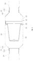
FIG. 1 is a schematic view of a filter provided by embodiments of the present disclosure. -
FIG. 2 is a sectional view of a filter provided by embodiments of the present disclosure. -
FIG. 3 is a schematic view of a filter connected to a refrigerant tube provided by embodiments of the present disclosure. -
FIG. 4 is a schematic view of a transition tube of a filter provided by embodiments of the present disclosure. -
FIG. 5 is a schematic view of a first connection manner between a transition tube and a casing of a filter provided by embodiments of the present disclosure. -
FIG. 6 is a schematic view of a second connection manner between a transition tube and a casing of a filter provided by embodiments of the present disclosure. -
FIG. 7 is a schematic view of a third connection manner between a transition tube and a casing of a filter provided by embodiments of the present disclosure. -
FIG. 8 is an exploded view of a filter screen assembly provided by embodiments of the present disclosure. -
FIG. 9 is a schematic view of a filter screen assembly provided by embodiments of the present disclosure. -
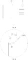
FIG. 10 is a schematic view of a support of a filter screen assembly according to a first implementation provided by embodiments of the present disclosure. -
FIG. 11 is a schematic view of a support of a filter screen assembly according to a second implementation provided by embodiments of the present disclosure. -
FIG. 12 is a schematic view of a support of a filter screen assembly according to a third implementation provided by embodiments of the present disclosure. - 10-casing 11-neck section 12-annular groove 111-tapered section 112-straight tube section 13-annular protrusion 20-transition tube 21-drawing lines 22-connecting section 23-covering section 30-filter screen assembly 40-refrigerant tube 3010-cylindrical filter screen 3011-opening 3012-annular body 3020-outer fixing ring 3021-outer bottom ring body 3022-outer side ring body 3030-inner fixing ring 3031-inner bottom ring body 3032-inner side ring body 3040-support 3041-U-shaped support strip 30411-edgefold 30412-inner recess 30413-outer protrusion
- The embodiments of the present disclosure are described in detail, examples of the embodiments are shown in the drawings. The same or similar elements and the elements having same or similar functions are denoted by like reference numerals throughout the descriptions. The embodiments described herein with reference to drawings are explanatory and intend to understand the present disclosure. The embodiments shall not be construed to limit the present disclosure.
- In the specification, it is to be understood that terms such as "length," "width," "upper," "lower," "front," "rear," "left," "right," "vertical," "horizontal," "top," "bottom," "inner," and "outer," should be construed to refer to the orientation as then described or as shown in the drawings under discussion. These relative terms are for convenience of description and do not require that the present invention be constructed or operated in a particular orientation.
- In addition, terms such as "first" and "second" are used herein for purposes of description and are not intended to indicate or imply relative importance or significance or to imply the number of indicated technical features. Thus, the feature defined with "first" and "second" may comprise one or more of this feature. In the description of the present invention, the term "a plurality of" means two or more than two, unless specified otherwise.
- In the present invention, unless specified or limited otherwise, the terms "mounted," "connected," "coupled," "fixed" and the like are used broadly, and may be, for example, fixed connections, detachable connections, or integral connections; may also be mechanical or electrical connections; may also be direct connections or indirect connections via intervening structures; may also be inner communications of two elements, which can be understood by those skilled in the art according to specific situations.
- As shown in
FIGS. 1 to 2 , a filter provided by embodiments of the present disclosure is mainly used in an air conditioner and for connecting arefrigerant tube 40. Specifically, the filter includes acasing 10, atransition tube 20 and afilter screen assembly 30. Thefilter screen assembly 30 is arranged in thecasing 10 and is fitted with and connected to an inner wall of thecasing 10. That thefilter screen assembly 30 is fitted with and connected to the inner wall of thecasing 10 refers to non-detachable connection or detachable connection. Thecasing 10 is an integrally formed piece. Since thecasing 10 is the integrally formed piece, integrally formed manufacturing can be achieved instead of splicing structures of carbon steel. The integrally formed piece can be made of other new material, preferably stainless steel or copper, free of spraying other than structures of carbon steel, thereby improving corrosion resistant performance of thecasing 10. - Furthermore, as shown in
FIGS. 1 to 3 , each of two axial ends of thecasing 10 has aneck section 11. Withneck sections 11 at two axial ends of thecasing 10, comparatively small joints can be formed at the two axial ends of thecasing 10, such that sizes of the twoneck sections 11 matches sizes of a mouth of thetransition tube 20, and thecasing 10 is easy to fixedly connected to thetransition tube 20. - With the filter of embodiments of the present disclosure, the
casing 10 is the integrally formed piece, splicing process is needless, on the premise that the strength and filtering effects of the filter are satisfied, steps for manufacturing thecasing 10 can be simplified, and the production efficiency of thecasing 10 can be raised. Meanwhile, the integrally formed piece can be made of new materials besides structures of carbon steel, it is needless to add a coating on an outer surface of thecasing 10, corrosion resistance is no longer good, and a process for spraying is saved, thereby raising the production efficiency of the filter. - More specifically, after the
casing 10 is integrally formed by new materials, an axial end of the casing 1 is necked, and then theneck section 11 is formed at the end; the other axial end of thefilter screen assembly 30 which is not been necked yet is pressed into thecasing 10, and thefilter screen assembly 30 is fixedly connected to the inner wall of thecasing 10; and finally the other axial end of thefilter screen assembly 30 which is not necked yet is necked, andtransition tubes 20 are fixedly connected to the twoneck sections 11. With thetransition tube 20, the filter can be conveniently connected to therefrigerant tube 40. - In some embodiments, as shown in
FIGS. 1 to 3 , theneck section 11 comprises a taperedsection 111 having a gradually reduced diameter and astraight tube section 112. Thestraight tube section 112 is connected to the taperedsection 111 and arranged in an axial direction. Thetransition tube 20 is fixedly connected to thestraight tube section 112. Specifically, the taperedsection 111 having the gradually reduced diameter can make thecasing 10 have gradually reduced spaces adjacent to the two axial ends thereof, which effectively prevents thefilter screen assembly 30 fixed in thecasing 10 from falling out from two ends of thecasing 10. In addition, thecasing 10 transmit from the taperedsection 111 to thestraight tube section 112 smoothly, and can be adapt to be connected to thetransition tube 20 via thestraight tube section 112. Since thetransition tube 20 is comparatively small, an auxiliary adaptor can be saved by means of thestraight tube section 112, thetransition tube 20 can be fixedly connected to thecasing 10 via connection between thestraight tube section 112 and thetransition tube 20. - In some embodiments, a preferable manner for fixedly connected the
transition tube 20 to thestraight tube section 112 is welding. Thetransition tube 20 is fixed to thestraight tube section 112 by welding can ensure good and stable connection and durable performance. In addition, because the welding process is simple and easy to operate, thetransition tube 20 and thestraight tube section 112 can be quickly assembled during manufacturing with high production efficiency. - In addition, the
transition tube 20 is welded to thestraight tube section 112 at a temperature higher than 810 °C, since thestraight tube section 112 is a part of thecasing 10, the welding temperature is higher than 810 °C during welding operation on thetransition tube 20 and thecasing 10, such that thetransition tube 20 is fixed at a high temperature, and the welding temperature is much lower than 810 °C when the filter is welded to therefrigerant tube 40 in the latter. The temperature at which therefrigerant tube 40 is welded does not affect stability of the welding position between thetransition tube 20 and thecasing 10, such that risks of leakage between thecasing 10 and thetransition tube 20 due to welding therefrigerant tube 40 can be effectively avoided. - Furthermore, as shown in
FIGS. 2 andFIG. 4 , thetransition tube 20 is embedded in to thestraight tube section 112, and thetransition tube 20 is provided withdrawing lines 21 at an outer wall in contact with thestraight tube section 112. That means the outer wall of a part of thetransition tube 20 embedded into thestraight tube section 112 is provided with the drawing lines 21, and thedrawing lines 21 can be formed by wire drawing process. With such design, during welding thetransition tube 20 and thestraight tube section 112, a welding flux can be well arranged through the drawing lines 21 on thetransition tube 20, the welding flux and a contact area between thestraight tube section 112 and thetransition tube 20 can be increased, stability and reliability of thetransition tube 20 and thestraight tube section 112 can be greatly improved after the are fixed by welding. - In some embodiments, as shown in
FIGS. 5 , a first structure for thetransition tube 20 is that an outer end of thetransition tube 20 is flush with an end of thestraight tube section 112. Specifically, thetransition tube 20 of this structure is entirely embedded into thestraight tube section 112 and fixed to thestraight tube section 112 by welding. In such manner, in the condition that the filter has a constant total length, thecasing 10 can be designed longer, that means the length of thecasing 10 is enlarged, such that thefilter screen assembly 30 provided in thecasing 10 can be designed to have a larger size, then thefilter screen assembly 30 has an increased effective filtering area, and the filtering quality is improved. - In some embodiments, as shown in
FIGS. 6 , a second structure for thetransition tube 20 is that and outer end of thetransition tube 20 extends out of thestraight tube section 112 and forms a connectingsection 22. Specifically, thetransition tube 20 of this structure has a connectingsection 22 extending out of thestraight tube section 112 at a certain distance, and the connectingsection 22 can be used to connect therefrigerant tube 40. An size of the connectingsection 22 can be designed as an optimized size to adapt to connection with therefrigerant tube 40, which is convenient to mount and will not be affected by a size of thestraight tube section 112. - In some embodiments, as shown in
FIGS. 7 , a third structure for thetransition tube 20 is that an outer of thetransition tube 20 extends out of thestraight tube section 112 and forms acovering section 23, the coveringsection 23 abuts against an end of thestraight tube section 112, and an outer wall of the coveringsection 23 is flush with an outer wall of thestraight tube section 11. Specifically, thetransition tube 20 of this structure has the coveringsection 23 used to cover the end of thestraight tube section 112, the end of thestraight tube section 112 can be isolated by the coveringsection 23, in such manner, the welding flux can be prevented from contacting thestraight tube section 112 when thetransition tube 20 is welded to therefrigerant tube 40, which raises the welding quality. - In some embodiments, the
filter screen assembly 30 can be fixedly connected to the inner of thecasing 10 at least by the two manners as follows. - According to a first manner, the
filter screen assembly 30 is fixed to the inner wall of thecasing 10 by welding. Because thefilter screen assembly 30 is fixed to the inner wall of thecasing 10 by welding, it can be ensured that the fixation of thefilter screen assembly 30 on the inner wall of is stable and reliable, and thefilter screen assembly 30 is not easy to fall off after fixation. - According to a second manner, as shown in
FIGS. 2 , at least oneannular groove 12 sunken towards the inner wall of thecasing 10 is defined on the outer wall of thecasing 10 by punching. The inner wall of thecasing 10 is provided with anannular protrusion 13 protruding out at a position corresponding to theannular groove 12. Thefilter screen assembly 30 is connected to theannular protrusion 13 by snapping. Theannular groove 12 is defined on the outer wall of thecasing 10 by punching, such that theannular groove 12 is sunken to form theannular protrusion 13 in thecasing 10. When thefilter screen assembly 30 is provided in thecasing 10, a structure of thefilter screen assembly 30 for implementing embedding connection and theannular protrusion 13 can be connected by snapping, such that thefilter screen assembly 30 can be fixed, and the assembling is convenient. - In addition, the
annular protrusion 13 can also serves for positioning and mounting, theannular groove 12 can play a role of limiting and indicating a mounting position of thefilter screen assembly 30. - The number of the
annular groove 12 can be set as two, or there, or more than three according to actual needs, similarly, two, or three, or more than threeannular protrusions 13 are formed. - As shown in
FIGS. 8 to 12 , afilter screen assembly 30 provided by embodiments of the present disclosure comprises acylindrical filter screen 3010, anouter fixing ring 3020, aninner fixing ring 3030 and asupport 3040. Theinner fixing ring 3030 is fixedly connected in theouter fixing ring 3020, and theinner fixing ring 3030 can be connected to theouter fixing ring 3020 by embedding or welding. On the one hand, theinner fixing ring 3030 is used to clamp and fix thecylindrical filter screen 3010, one the other hand, theinner fixing ring 3030 is used to connected to thesupport 3040. Thecylindrical filter screen 3010 has anopening 3011, a circumferential edge of theopening 3011 is interposed between theinner fixing ring 3030 and theouter fixing ring 3020. Thesupport 3040 comprises at least oneU-shaped support strip 3041, eachU-shaped support strip 3041 and extends into thecylindrical filter screen 3010 through theopening 3011 and supports thecylindrical filter screen 3010, and two tail ends of eachU-shaped support strip 3041 are both fixedly connected to theinner fixing ring 3030, thecylindrical filter screen 3010 is fixed by theinner fixing ring 3030 and theouter fixing ring 3020, and is supported by thesupport 3040 to be kept in a cylindrical state, to effectively show its filtering effect. - The number of the
U-shaped support strip 3041 can be set according to actual needs. As shown inFIGS. 10 to 11 , may be one, or two, or three, or more than three U-shaped support strips are provided for example. In addition, eachU-shaped support strip 3041 is used for supporting separately. If more than two U-shaped support strips 3041 are provided, the U-shaped support strips are assembled and connected after each singleU-shaped support strip 3041 is manufactured, there is no need to integrally form thesupport 3040, material waste can be reduced to the minimum. At the meantime, length elongation can be implemented during manufacturing due to the singleU-shaped support strip 3041 has a small structure. Thesupport 3040 formed in this manner can have a longer length, correspondingly, thecylindrical filter screen 3010 can be designed to have a longer length, and thecylindrical filter screen 3010 is lager in effective filtering area. - As for the
filter screen assembly 30 of embodiments of the present disclosure, since thesupport 3040 is formed by connecting at least oneU-shaped support strip 3041, there is no need to integrally form thesupport 3040, each singleU-shaped support strip 3041 can be manufactured separately. In such manner, not only material waste caused by that thesupport 3040 is integrally formed can be reduced. In the meantime, length elongation can be implemented during manufacturing due to the singleU-shaped support strip 3041 has an elongated structure. Thesupport 3040 manufactured by theU-shaped support strip 3041 can have a longer length, thecylindrical filter screen 3010 can be designed to have a larger size, and thecylindrical filter screen 3010 which can be supported by thesupport 3040 is lager in effective filtering area, thereby the filtering effect of thefilter screen assembly 30 can be greatly improved. - In some embodiments, two tail end of each
U-shaped support strip 3041 are both bent intoedgefolds 30411, and theedgefolds 30411 abut against theinner fixing ring 3030 and are fixed to theinner fixing ring 3030 by spot welding. Specifically, theedgefolds 30411 can abut against theinner fixing ring 3030, one the one hand positioning is achieved, and one the other hand the contact area between the edgefolds and theinner fixing ring 3030 can be increased. Theedgefold 30411 is fixed to theinner fixing ring 3030 by once-through spot welding, the connection is good in stability. - In some embodiments, more than two U-shaped support strips 3041 are provided, and bottoms of adjacent two U-shaped support strips 3041 are fixed by spot welding. When more than two U-shaped support strips 3041 are provided, two adjacent (upper and down) support stripes are fixed together by once-through spot welding, the operation is simple and convenient, and the connection is good in stability.
- In some embodiments, more than two U-shaped support strips 3041 are provided, the U-shaped support strips 3041 uniformly cross each other at midpoints of bottoms thereof. With such design, the U-shaped support strips 3041 of the
support 3040 are uniformly and radially distributed about a center, i.e. the midpoints of the bottoms. After the support supports thecylindrical filter screen 3010 in this manner, thecylindrical filter screen 3010 can be supported at positions with uniform force. - In some embodiments, as shown in
FIGS. 8 to 12 , an upper surface and a lower surface of a bottom of eachU-shaped support strip 3041 are provided with aninner recess 30412 and anouter protrusion 30413 respectively, and positions of theinner recess 30412 and theouter protrusion 30413 correspond to each other, adjacent two U-shaped support strips 3041 are positioned by means of cooperation between theinner recess 30412 and theouter protrusion 30413. Alternatively, an upper surface and a lower surface of a bottom of eachU-shaped support strip 3041 are provided with anouter protrusion 30413 and aninner recess 30412 respectively, and positions of theouter protrusion 30413 and theinner recess 30412 correspond to each other, adjacent twoU-shaped support strip 3041 are positioned by means of cooperation between theinner recess 30412 and theouter protrusion 30413. That means, when more than two U-shaped support strips 3041 are provided, bottoms of the two adjacent U-shaped support strips 3041 in an up-down direction are positioned by means of cooperation between theouter protrusion 30413 and theinner recess 30412, and then the two adjacent U-shaped support strips 3041 in an up-down direction are fixed by spot welding, the U-shaped support strips 3041 can be conveniently assembled, in addition, the assembledsupport 3040 is good in uniformity and better in quality. - As shown in
FIGS. 8 , in some embodiments, a circumferential edge of theopening 3011 is bent into anannular body 3012 in a radial direction, theannular body 3012 is interposed between theinner fixing ring 3030 and theouter fixing ring 3020. Specifically, by arranging theannular body 3012 between theinner fixing ring 3030 and theouter fixing ring 3020, theinner fixing ring 3030 and theouter fixing ring 3020 tightly press theannular body 3012 after theinner fixing ring 3030 and theouter fixing ring 3020 are fixedly connected together by spot welding, such that thecylindrical filter screen 3010 is fixed. - The
annular body 3012 is a part of thecylindrical filter screen 3010, theannular body 3012 is bent in a radial direction at a circumferential edge of theopening 3011 to include an angle about 90 degrees together with thecylindrical filter screen 3010. - Preferably, the
cylindrical filter screen 3010 has a conical or cylindrical vertical section. An inner diameter of theopening 3011 of thecylindrical filter screen 3010 is greater than or equal to an inner diameter of another end opposite theopening 3011 of thecylindrical filter screen 3010. - As shown in
FIGS. 8 , in some embodiments, theouter fixing ring 3020 comprises an outerbottom ring body 3021 and an outerside ring body 3022, the outerside ring body 3022 is connected to a circumferential edge of the outerbottom ring body 3021 and extends in a radial direction. The outerside ring body 3022 and the outerbottom ring body 3021 are integrally formed as theouter fixing ring 3020. Theinner fixing ring 3030 comprises an innerbottom ring body 3031 and an innerside ring body 3032, and the innerside ring body 3032 is connected to a circumferential edge of the innerbottom ring body 3031 and extends in the radial direction. The innerside ring body 3032 and the innerbottom ring body 3031 are integrally formed as theinner fixing ring 3030. - Furthermore, the inner
side ring body 3032 abuts against an inner surface of the outerside ring body 3022, the innerside ring body 3032 is fitted with the outerside ring body 3022 to limit each other to achieve positioning. The innerbottom ring body 3031 abuts against an upper surface of the outerbottom ring body 3021 and is fixed to the outerbottom ring body 3021 by spot welding. A plurality of spot welding points are distributed in an annular manner, and the innerbottom ring body 3031 is fixed to the outerbottom ring body 3021 by spot welding. On the one hand, operation is easy, and on the other hand, connection can be ensured to be good in stability. The circumferential edge of theopening 3011 is interposed between the innerbottom ring body 3031 and the outerbottom ring body 3021. Specifically, theannular body 3012 provided on the circumferential edge of theopening 3011 is interposed between the innerbottom ring body 3031 and the outerbottom ring body 3021, theannular body 3012 is fixed by clamping force generated by the welded the innerbottom ring body 3031 and the outerbottom ring body 3021, and thecylindrical filter screen 3010 is fixed in such manner. - As shown in
FIGS. 2 , since the filter of embodiments of the present disclosure is provided with thefilter screen assembly 30 described above, because thesupport 3040 can be manufactured to have a longer length without increase in cost, correspondingly thecylindrical filter screen 3010 can be designed to have a larger size, such that thefilter screen assembly 30 has a better filtering effect and the filter is better in filtering. - As shown in
FIGS. 1 to 3 , this embodiment provides a manufacturing method for a filter. The manufacturing method comprises the following steps. - At S01, a material free of spraying is provided, and a
casing 10 is integrally formed from the material free of spraying. - At S02, a first axial end of the
casing 10 is necked to form aneck section 11. - At S03, a
filter screen assembly 30 is provided, thefilter screen assembly 30 is pressed in through a second axial end of thecasing 10 and fitted with and connected to an inner wall of thecasing 10. - At S04, the second axial end of the
casing 10 is necked to form aneck section 11. - At S05, the
neck sections 11 at two axial ends of the casing 1 are connected to transitiontubes 20 respectively. Thetransition tubes 20 are used for connecting to arefrigerant tube 40. - As for the filter manufactured by the manufacturing method for a filter of embodiments of the present disclosure, the
casing 10 is integrally manufactured by a new material other than carbon steel, splicing process is needless, on the premise that the strength and filtering effects of the filter are satisfied, steps for manufacturing thecasing 10 can be simplified, and the production efficiency of thecasing 10 can be raised. Meanwhile, corrosion resistance of the casing is improved, the outer surface of thecasing 10 needs no sprayed coating, and a process for spraying is saved, thereby raising the production efficiency of the filter. - At S03 of this embodiment, the fitting between the
filter screen assembly 30 and the inner wall of thecasing 10 at least can be achieved by the following two manners. - According to a first manner, the
filter screen assembly 30 is fixed to the inner wall of thecasing 10 by welding. Because thefilter screen assembly 30 is fixed to the inner wall of thecasing 10 by welding, it can be ensured that the fixation of thefilter screen assembly 30 on the inner wall of is stable and reliable, and thefilter screen assembly 30 is not easy to fall off after fixation. - According to a second manner, at least one
annular groove 12 sunken towards the inner wall of thecasing 10 is defined on an outer wall of thecasing 10 by punching, such that the inner wall of thecasing 10 protrudes to form anannular protrusion 13 with theannular groove 12. Thefilter screen assembly 30 is connected to theannular protrusion 13 by snapping. Specifically theannular groove 12 is defined on the outer wall of thecasing 10 by punching, such that theannular groove 12 is sunken to form theannular protrusion 13 in thecasing 10. When thefilter screen assembly 30 is provided in thecasing 10, a structure of thefilter screen assembly 30 for implementing embedding connection and theannular protrusion 13 can be connected by snapping, such that thefilter screen assembly 30 can be fixed, and the assembling is convenient. - In addition, the
annular protrusion 13 can also serves for positioning and mounting, theannular groove 12 can play a role of limiting and indicating a mounting position of thefilter screen assembly 30. - The number of the
annular groove 12 can be set as two, or there, or more than three according to actual needs, similarly, two, or three, or more than threeannular protrusions 13 are formed. - For example, at S03, one
annular groove 12 sunken towards the inner wall of thecasing 10 is defined on an outer wall of thecasing 10 by punching, such that the inner wall of thecasing 10 protrudes to form anannular protrusion 13 with theannular groove 12. When thefilter screen assembly 30 is pressed into thecasing 10, an end of thefilter screen assembly 30 is flush with theannular protrusion 13. Another oneannular groove 12 sunken towards the inner wall of thecasing 10 is defined on an outer wall of thecasing 10 by punching, such that the inner wall of thecasing 10 protrudes to form anannular protrusion 13 with theannular groove 12. The twoannular protrusions 13 hold the end of thefilter screen assembly 30, such that the end of thefilter screen assembly 30 is snapped to the inner wall of thecasing 10. - Furthermore, at S05, the
transition tube 20 is fixed to theneck section 11 by welding, and stability of connection between thetransition tube 20 and theneck section 11 can be enhanced by welding. - Furthermore, at S05, the
transition tube 20 is welded to thestraight tube section 112 at a temperature higher than 810 °C, since thestraight tube section 112 is a part of thecasing 10, the welding temperature is higher than 810 °C during welding operation on thetransition tube 20 and thecasing 10, such that thetransition tube 20 is fixed at a high temperature, and the welding temperature is much lower than 810 °C when the filter is welded to therefrigerant tube 40 in the latter. The temperature at which therefrigerant tube 40 is welded does not affect stability of the welding position between thetransition tube 20 and thecasing 10, such that risks of leakage between thecasing 10 and thetransition tube 20 due to welding therefrigerant tube 40 can be effectively avoided. - Preferably, at S01, the material free of spraying is stainless steel or copper. The integrally formed casing 10 made of steel or copper can effective improve corrosion resistant performance of the
casing 10. - This embodiment provides an air conditioner, and the air conditioner comprises a
refrigerant tube 40 and the above filter. Therefrigerant tube 40 is fixedly connected to thetransition tube 20. Specifically, the air conditioner of embodiments of the present disclosure is provided with the above filter, the production efficiency of the filter of the air conditioner can be increased, and thecasing 10 of the filter is integrally formed of new material other than carbon steel, a coating is no longer needed to be sprayed on the outer of thecasing 10, risks of leakage connection between thecasing 10 and thetransition tube 20 because the coating on the casing is easy to burn out is reduced, such that the air conditioner can be used more safely. - To sum up, the present application aims to provide a filter, a manufacturing method for the filter, and an air conditioner, in order to overcome defects in the related art that the manufacturing processes are complex, the production efficiency is low, and the coating on the surface is easy to burn off due to that the filter is spliced by carbon steel.
- The present disclosure brings about the beneficial effects as follows. The casing of the filter of the present disclosure is an integrally formed piece, splicing process is needless, on the premise that the strength and filtering effects of the filter are satisfied, steps for manufacturing the casing can be simplified, and the production efficiency of the casing can be raised. Meanwhile, the integrally formed piece is made of new materials with good corrosion resistance other than carbon steel, it is needless to add a coating on an outer surface of the casing, and a process for spraying is saved, thereby raising the production efficiency of the filter.
- As for the filter manufactured by the manufacturing method for a filter of the present disclosure, the casing is an integrally formed piece made of new materials than carbon steel, splicing process is needless, on the premise that the strength and filtering effects of the filter are satisfied, steps for manufacturing the casing can be simplified, and the production efficiency of the casing can be raised. Meanwhile, the corrosion resistance of the casing is improved it is needless to add a coating on an outer surface of the casing, and a process for spraying is saved, thereby raising the production efficiency of the filter.
- The air conditioner of the present disclosure is provided with the above filter, the production efficiency of the filter of the air conditioner can be raised. Meanwhile, the casing of the filter is integrally formed of new material other than carbon steel, a coating is no longer needed to be sprayed on the outer of the casing, risks of leakage at connection between the casing and the transition tube because the coating is easy to burn out is reduced, such that the air conditioner can be used more safely.
- The above are only preferable embodiments and shall not be construed to limit the present disclosure. Changes, alternatives, and modifications can be made in the embodiments without departing from spirit, principles and scope of the present disclosure.
Claims (23)
- A filter, comprising:a casing;a transition tube; anda filter screen assembly provided in the casing, fitted with and connected to an inner wall of the casing, the casing being an integrally formed piece, each of two axial ends of the casing has a neck section , and the two neck sections being fixedly connected to the transition tube.
- The filter according to claim 1, wherein the neck section comprises a tapered section having a gradually reduced diameter and a straight tube section, the straight tube section is connected to the tapered section and arranged in an axial direction, and the transition tube is fixedly connected to the straight tube section.
- The filter according to claim 2, wherein the transition tube is embedded into the straight tube section, and an outer wall of the transition tube in contact with the straight tube section is provided with drawing lines.
- The filter according to claim 2 or 3, wherein an outer end of the transition tube is flush with an end of the straight tube section.
- The filter according to claim 2 or 3, wherein an outer end of the transition tube extends out of the straight tube section and forms a connecting section.
- The filter according to claim 2 or 3, wherein an outer end of the transition tube extends out of the straight tube section and forms a covering section, the covering section abuts against an end of the straight tube section, and an outer wall of the covering section is flush with an outer wall of the straight tube section.
- The filter according to any one of claims 1 to 6, wherein at least one annular groove sunken towards the inner wall of the casing is provided on an outer wall of the casing by punching, the inner wall of the casing is provided with an annular protrusion protruding from a position corresponding to the annular groove, and the filter screen assembly is connected to the annular protrusion by snapping.
- The filter according to any one of claims 1 to 7, wherein the casing is integrally formed from stainless steel or copper.
- The filter according to any one of claims 1 to 8, wherein the filter screen assembly comprises a cylindrical filter screen, an outer fixing ring, an inner fixing ring and a support; the inner fixing ring is fixedly connected into the outer fixing ring, the cylindrical filter screen has an opening, a circumferential edge of the opening is interposed between the inner fixing ring and the outer fixing ring; the support comprises at least one U-shaped support strip, each U-shaped support strip extends into the cylindrical filter screen through the opening and supports the cylindrical filter screen, and two ends of each U-shaped support strip are both fixedly connected to the inner fixing ring.
- The filter according to claim 9, wherein the two ends of each U-shaped support strip are bent into flanges, and the flangeabuts against the inner fixing ring and are fixed to the inner fixing ring by spot welding.
- The filter according to claim 9 or 10, wherein more than two U-shaped support strips are provided, and bottoms of two adjacent U-shaped support strips are fixed by spot welding.
- The filter according to any one of claims 9 to 11, wherein more than two U-shaped support strips are provided, and the U-shaped support strips are uniformly arranged by crossing each other at midpoints of bottoms thereof.
- The filter according to claim 11 or 12, wherein an upper surface and a lower surface of the bottom of each U-shaped support strip are provided with an inner recess and an outer protrusion respectively, and positions of the inner recess and the outer protrusion correspond to each other, two adjacent U-shaped support strips are positioned by engaging the inner recess and the outer protrusion; or
an upper surface and a lower surface of the bottom of each U-shaped support strip are provided with an outer protrusion and an inner recess respectively, and positions of the outer protrusion and the inner recess correspond to each other, two adjacent U-shaped support strip are positioned by engaging the inner recess and the outer protrusion. - The filter according to any one of claims 9 to 13, wherein the circumferential edge of the opening is bent into an annular body in a radial direction, and the annular body is interposed between the inner fixing ring and the outer fixing ring.
- The filter according to any one of claims 9 to 14, wherein the cylindrical filter screen has a conical or cylindrical shape.
- The filter according to any one of claims 9 to 15, wherein the outer fixing ring comprises an outer bottom ring body and an outer side ring body, and the outer side ring body is connected to a circumferential edge of the outer bottom ring body and extending in an axial direction, and the inner fixing ring comprises an inner bottom ring body and an inner side ring body, and the inner side ring body is connected to a circumferential edge of the inner bottom ring body and extends in the axial direction; and
the inner side ring body abuts against an inner surface of the outer side ring body, the inner bottom ring body abuts against an upper surface of the outer bottom ring body and is fixed to the outer bottom ring body by spot welding, and the circumferential edge of the opening is interposed between the inner bottom ring body and the outer bottom ring body. - A manufacturing method for a filter, wherein comprising:providing a material free of spraying and integrally forming a casing from the material free of spraying (S01);necking a first axial end of the casing to form a neck section (S02);providing a filter screen assembly, pressing a filter screen assembly through a second axial end of the casing and enabling the filter screen assembly to be fitted with and connected to an inner wall of the casing (S03);necking the second axial end of the casing to form another neck section (S04); andconnecting a transition tube to the neck section at each of the two axial ends of the casing respectively (S05).
- The manufacturing method according to claim 17, wherein in S03, the filter screen assembly is fixed to an inner wall of the casing by welding.
- The manufacturing method according to claim 17, wherein in S03, at least one annular groove sunken towards the inner wall of the casing is provided on an outer wall of the casing by punching, such that the inner wall of the casing protrudes to form an annular protrusion, and the filter screen assembly is connected to the annular protrusion by snapping.
- The manufacturing method according to claim 19, wherein in S03, a first annular groove sunken towards the inner wall of the casing is provided on the outer wall of the casing (10) by punching, such that the inner wall of the casing protrudes to form a first annular protrusion, when the filter screen assembly is pressed into the casing, an end of the filter screen assembly is flush with the first annular protrusion, a second annular groove sunken towards the inner wall of the casing is provided on the outer wall of the casing by punching, such that the inner wall of the casing protrudes to form a second annular protrusion , and the first and the second annular protrusions hold the end of the filter screen assembly.
- The manufacturing method according to any one of claims 17 to 20, wherein in S01, the material free of spraying is stainless steel or copper.
- The manufacturing method according to any one of claims 17 to 21, wherein in S05, the transition tube is fixed to the neck section by spot welding.
- An air conditioner, comprising: a refrigerant tube and the filter according to any one of claims 1 to 16, the refrigerant tube being fixedly connected to the transition tube.
Applications Claiming Priority (4)
| Application Number | Priority Date | Filing Date | Title |
|---|---|---|---|
| CN201810676450.0A CN108758900A (en) | 2018-06-27 | 2018-06-27 | Filter, the manufacturing method of filter and air conditioner |
| CN201821005858.7U CN208442980U (en) | 2018-06-27 | 2018-06-27 | Filters and Air Conditioners |
| CN201821004410.3U CN208487852U (en) | 2018-06-27 | 2018-06-27 | Filter assembly and refrigerant pipe filter |
| PCT/CN2018/124324 WO2020000964A1 (en) | 2018-06-27 | 2018-12-27 | Filter, manufacturing method for filter and air conditioner |
Publications (3)
| Publication Number | Publication Date |
|---|---|
| EP3657083A1 true EP3657083A1 (en) | 2020-05-27 |
| EP3657083A4 EP3657083A4 (en) | 2020-12-02 |
| EP3657083B1 EP3657083B1 (en) | 2023-01-25 |
Family
ID=68984679
Family Applications (1)
| Application Number | Title | Priority Date | Filing Date |
|---|---|---|---|
| EP18924370.2A Active EP3657083B1 (en) | 2018-06-27 | 2018-12-27 | Filter, manufacturing method for filter and air conditioner |
Country Status (4)
| Country | Link |
|---|---|
| US (2) | US11598553B2 (en) |
| EP (1) | EP3657083B1 (en) |
| ES (1) | ES2939277T3 (en) |
| WO (1) | WO2020000964A1 (en) |
Cited By (1)
| Publication number | Priority date | Publication date | Assignee | Title |
|---|---|---|---|---|
| FR3148080A1 (en) * | 2023-04-19 | 2024-10-25 | Hydrodiv | Air filtration device |
Families Citing this family (4)
| Publication number | Priority date | Publication date | Assignee | Title |
|---|---|---|---|---|
| DE102020006967A1 (en) * | 2020-11-13 | 2022-05-19 | Truma Gerätetechnik GmbH & Co. KG | Portable air conditioner |
| CN114053772A (en) * | 2021-11-01 | 2022-02-18 | 江苏通用环保集团有限公司 | Domestic sewage filtering device |
| CN220589337U (en) * | 2023-06-30 | 2024-03-15 | 浙江盾安禾田金属有限公司 | Filtering component and filter |
| CN117101267A (en) * | 2023-08-28 | 2023-11-24 | 苏州双荣橡塑有限公司 | A bell-shaped plastic filter and its production method |
Family Cites Families (23)
| Publication number | Priority date | Publication date | Assignee | Title |
|---|---|---|---|---|
| JPH06235570A (en) | 1993-02-10 | 1994-08-23 | Matsushita Refrig Co Ltd | Refrigating plant |
| US5635058A (en) * | 1994-03-07 | 1997-06-03 | Bowman Dennis E | Reject water drain line installation system and apparatus for under sink reverse osmosis filter system |
| JPH10296432A (en) | 1997-05-02 | 1998-11-10 | Keiji Matsumoto | High frequency brazing method |
| JP2922201B1 (en) * | 1998-07-21 | 1999-07-19 | 株式会社三五 | Spinning method and its equipment |
| WO2003064941A1 (en) | 2002-01-25 | 2003-08-07 | Sporlan Valve Company | Molded core filter drier |
| US6852150B2 (en) * | 2002-01-25 | 2005-02-08 | Sporlan Valve Company | Molded core filter drier |
| JP4318904B2 (en) | 2002-10-31 | 2009-08-26 | ダイキン工業株式会社 | filter |
| CN2733273Y (en) * | 2004-07-10 | 2005-10-12 | 湖州盛昌机械有限公司 | Liquid storage cartridge of air conditioner |
| CN100453931C (en) * | 2006-08-17 | 2009-01-21 | 浙江盾安人工环境设备股份有限公司 | Noise reducer for air conditioner, filter and filter drying |
| CN201482295U (en) * | 2009-08-24 | 2010-05-26 | 汇投投资有限公司 | Metallic filter for air conditioner |
| US20110132817A1 (en) * | 2009-12-03 | 2011-06-09 | Eric Rankin Gardner | Systems and methods associated with straining a pipeline |
| JP2012021759A (en) * | 2010-07-15 | 2012-02-02 | Ichimon Kiko Kk | Air cleaning apparatus |
| CN107013783B (en) * | 2013-10-10 | 2019-01-29 | 新昌县四通机电有限公司 | A kind of muffler |
| CN204006844U (en) | 2014-07-21 | 2014-12-10 | 美的集团武汉制冷设备有限公司 | Filter and there is its air-conditioner |
| CN105299976A (en) * | 2014-07-21 | 2016-02-03 | 美的集团武汉制冷设备有限公司 | Filter and air conditioner with same |
| CN204460868U (en) | 2015-02-28 | 2015-07-08 | 浙江景加源机械有限公司 | A kind of filter |
| CN204841230U (en) * | 2015-08-12 | 2015-12-09 | 青海时代新能源科技有限公司 | Powder filter equipment |
| CN107345603A (en) | 2016-05-06 | 2017-11-14 | 珠海华宇金属有限公司 | A kind of nozzle structure and its liquid reservoir |
| CN107127467A (en) | 2017-04-13 | 2017-09-05 | 广东美的暖通设备有限公司 | Welding method, air conditioning pipe system and the air conditioner of idle call shock absorbing pipe |
| CN207377770U (en) | 2017-06-28 | 2018-05-18 | 周国范 | Damping and silencing pipe, refrigeration system and air conditioner and refrigeration machine |
| CN207214399U (en) | 2017-09-29 | 2018-04-10 | 沈学明 | A kind of stainless steel muffler |
| CN208442980U (en) | 2018-06-27 | 2019-01-29 | 广东美的暖通设备有限公司 | Filters and Air Conditioners |
| CN108758900A (en) * | 2018-06-27 | 2018-11-06 | 广东美的暖通设备有限公司 | Filter, the manufacturing method of filter and air conditioner |
-
2018
- 2018-12-27 US US16/631,822 patent/US11598553B2/en active Active
- 2018-12-27 ES ES18924370T patent/ES2939277T3/en active Active
- 2018-12-27 EP EP18924370.2A patent/EP3657083B1/en active Active
- 2018-12-27 WO PCT/CN2018/124324 patent/WO2020000964A1/en not_active Ceased
-
2023
- 2023-02-03 US US18/163,875 patent/US11828485B2/en active Active
Cited By (1)
| Publication number | Priority date | Publication date | Assignee | Title |
|---|---|---|---|---|
| FR3148080A1 (en) * | 2023-04-19 | 2024-10-25 | Hydrodiv | Air filtration device |
Also Published As
| Publication number | Publication date |
|---|---|
| US20200149777A1 (en) | 2020-05-14 |
| US11828485B2 (en) | 2023-11-28 |
| US11598553B2 (en) | 2023-03-07 |
| US20230184458A1 (en) | 2023-06-15 |
| EP3657083A4 (en) | 2020-12-02 |
| ES2939277T3 (en) | 2023-04-20 |
| EP3657083B1 (en) | 2023-01-25 |
| WO2020000964A1 (en) | 2020-01-02 |
Similar Documents
| Publication | Publication Date | Title |
|---|---|---|
| US11828485B2 (en) | Filter, manufacturing method for filter and air conditioner | |
| CN215372883U (en) | Plumbing Components and Air Conditioning Systems | |
| EP4350275A1 (en) | Connector and heat exchanger having same | |
| CN208442980U (en) | Filters and Air Conditioners | |
| CN210211896U (en) | Wheel of vehicle | |
| GB2362257A (en) | Weldless support structure and electrical connections in a hid lamp | |
| CN216895213U (en) | Connecting structure of telescopic pipe | |
| CN216990276U (en) | Improve screw thread ring groove structure of effect of brazing | |
| CN219624257U (en) | Liner structure and water heater | |
| WO2025001363A1 (en) | Filter assembly and filter | |
| CN213878024U (en) | Flexible Filament Lamp | |
| CN214466939U (en) | Quick connector | |
| CN213635903U (en) | Flexible Filament Lamp | |
| EP3892859B1 (en) | Compressor liquid accumulator and compressor comprising same | |
| CN204144462U (en) | The assembly of coaxial cable and connector, weld-ring and connector | |
| CN210793351U (en) | Special-shaped pipe and vehicle framework with same | |
| CN217302088U (en) | Assembled pipe fitting connects convenient to installation | |
| CN208266888U (en) | A kind of nipple for bracing members connection | |
| CN220303503U (en) | Novel panel light | |
| CN223809252U (en) | A novel heating wire welding and fixing structure | |
| CN207449812U (en) | A kind of pipeline via sheath and automobile | |
| CN217109980U (en) | Machine in connecting tube subassembly and air conditioning | |
| CN219865632U (en) | Hanging bracket device of ceiling fan | |
| CN224188807U (en) | Distributor for refrigerating system | |
| CN219713145U (en) | Iron wire lampshade |
Legal Events
| Date | Code | Title | Description |
|---|---|---|---|
| STAA | Information on the status of an ep patent application or granted ep patent |
Free format text: STATUS: THE INTERNATIONAL PUBLICATION HAS BEEN MADE |
|
| PUAI | Public reference made under article 153(3) epc to a published international application that has entered the european phase |
Free format text: ORIGINAL CODE: 0009012 |
|
| STAA | Information on the status of an ep patent application or granted ep patent |
Free format text: STATUS: REQUEST FOR EXAMINATION WAS MADE |
|
| 17P | Request for examination filed |
Effective date: 20200218 |
|
| AK | Designated contracting states |
Kind code of ref document: A1 Designated state(s): AL AT BE BG CH CY CZ DE DK EE ES FI FR GB GR HR HU IE IS IT LI LT LU LV MC MK MT NL NO PL PT RO RS SE SI SK SM TR |
|
| AX | Request for extension of the european patent |
Extension state: BA ME |
|
| A4 | Supplementary search report drawn up and despatched |
Effective date: 20201103 |
|
| RIC1 | Information provided on ipc code assigned before grant |
Ipc: B01D 46/00 20060101ALI20201028BHEP Ipc: B01D 46/24 20060101ALI20201028BHEP Ipc: F24F 3/16 20060101AFI20201028BHEP Ipc: F24F 13/28 20060101ALI20201028BHEP |
|
| STAA | Information on the status of an ep patent application or granted ep patent |
Free format text: STATUS: EXAMINATION IS IN PROGRESS |
|
| 17Q | First examination report despatched |
Effective date: 20210903 |
|
| DAV | Request for validation of the european patent (deleted) | ||
| DAX | Request for extension of the european patent (deleted) | ||
| GRAP | Despatch of communication of intention to grant a patent |
Free format text: ORIGINAL CODE: EPIDOSNIGR1 |
|
| STAA | Information on the status of an ep patent application or granted ep patent |
Free format text: STATUS: GRANT OF PATENT IS INTENDED |
|
| INTG | Intention to grant announced |
Effective date: 20221107 |
|
| GRAS | Grant fee paid |
Free format text: ORIGINAL CODE: EPIDOSNIGR3 |
|
| GRAA | (expected) grant |
Free format text: ORIGINAL CODE: 0009210 |
|
| STAA | Information on the status of an ep patent application or granted ep patent |
Free format text: STATUS: THE PATENT HAS BEEN GRANTED |
|
| AK | Designated contracting states |
Kind code of ref document: B1 Designated state(s): AL AT BE BG CH CY CZ DE DK EE ES FI FR GB GR HR HU IE IS IT LI LT LU LV MC MK MT NL NO PL PT RO RS SE SI SK SM TR |
|
| REG | Reference to a national code |
Ref country code: GB Ref legal event code: FG4D |
|
| REG | Reference to a national code |
Ref country code: CH Ref legal event code: EP |
|
| REG | Reference to a national code |
Ref country code: AT Ref legal event code: REF Ref document number: 1546155 Country of ref document: AT Kind code of ref document: T Effective date: 20230215 Ref country code: IE Ref legal event code: FG4D |
|
| REG | Reference to a national code |
Ref country code: DE Ref legal event code: R096 Ref document number: 602018045864 Country of ref document: DE |
|
| REG | Reference to a national code |
Ref country code: ES Ref legal event code: FG2A Ref document number: 2939277 Country of ref document: ES Kind code of ref document: T3 Effective date: 20230420 |
|
| REG | Reference to a national code |
Ref country code: LT Ref legal event code: MG9D |
|
| REG | Reference to a national code |
Ref country code: NL Ref legal event code: MP Effective date: 20230125 |
|
| REG | Reference to a national code |
Ref country code: AT Ref legal event code: MK05 Ref document number: 1546155 Country of ref document: AT Kind code of ref document: T Effective date: 20230125 |
|
| PG25 | Lapsed in a contracting state [announced via postgrant information from national office to epo] |
Ref country code: NL Free format text: LAPSE BECAUSE OF FAILURE TO SUBMIT A TRANSLATION OF THE DESCRIPTION OR TO PAY THE FEE WITHIN THE PRESCRIBED TIME-LIMIT Effective date: 20230125 |
|
| P01 | Opt-out of the competence of the unified patent court (upc) registered |
Effective date: 20230526 |
|
| PG25 | Lapsed in a contracting state [announced via postgrant information from national office to epo] |
Ref country code: RS Free format text: LAPSE BECAUSE OF FAILURE TO SUBMIT A TRANSLATION OF THE DESCRIPTION OR TO PAY THE FEE WITHIN THE PRESCRIBED TIME-LIMIT Effective date: 20230125 Ref country code: PT Free format text: LAPSE BECAUSE OF FAILURE TO SUBMIT A TRANSLATION OF THE DESCRIPTION OR TO PAY THE FEE WITHIN THE PRESCRIBED TIME-LIMIT Effective date: 20230525 Ref country code: NO Free format text: LAPSE BECAUSE OF FAILURE TO SUBMIT A TRANSLATION OF THE DESCRIPTION OR TO PAY THE FEE WITHIN THE PRESCRIBED TIME-LIMIT Effective date: 20230425 Ref country code: LV Free format text: LAPSE BECAUSE OF FAILURE TO SUBMIT A TRANSLATION OF THE DESCRIPTION OR TO PAY THE FEE WITHIN THE PRESCRIBED TIME-LIMIT Effective date: 20230125 Ref country code: LT Free format text: LAPSE BECAUSE OF FAILURE TO SUBMIT A TRANSLATION OF THE DESCRIPTION OR TO PAY THE FEE WITHIN THE PRESCRIBED TIME-LIMIT Effective date: 20230125 Ref country code: HR Free format text: LAPSE BECAUSE OF FAILURE TO SUBMIT A TRANSLATION OF THE DESCRIPTION OR TO PAY THE FEE WITHIN THE PRESCRIBED TIME-LIMIT Effective date: 20230125 Ref country code: AT Free format text: LAPSE BECAUSE OF FAILURE TO SUBMIT A TRANSLATION OF THE DESCRIPTION OR TO PAY THE FEE WITHIN THE PRESCRIBED TIME-LIMIT Effective date: 20230125 |
|
| PG25 | Lapsed in a contracting state [announced via postgrant information from national office to epo] |
Ref country code: SE Free format text: LAPSE BECAUSE OF FAILURE TO SUBMIT A TRANSLATION OF THE DESCRIPTION OR TO PAY THE FEE WITHIN THE PRESCRIBED TIME-LIMIT Effective date: 20230125 Ref country code: PL Free format text: LAPSE BECAUSE OF FAILURE TO SUBMIT A TRANSLATION OF THE DESCRIPTION OR TO PAY THE FEE WITHIN THE PRESCRIBED TIME-LIMIT Effective date: 20230125 Ref country code: IS Free format text: LAPSE BECAUSE OF FAILURE TO SUBMIT A TRANSLATION OF THE DESCRIPTION OR TO PAY THE FEE WITHIN THE PRESCRIBED TIME-LIMIT Effective date: 20230525 Ref country code: GR Free format text: LAPSE BECAUSE OF FAILURE TO SUBMIT A TRANSLATION OF THE DESCRIPTION OR TO PAY THE FEE WITHIN THE PRESCRIBED TIME-LIMIT Effective date: 20230426 Ref country code: FI Free format text: LAPSE BECAUSE OF FAILURE TO SUBMIT A TRANSLATION OF THE DESCRIPTION OR TO PAY THE FEE WITHIN THE PRESCRIBED TIME-LIMIT Effective date: 20230125 |
|
| REG | Reference to a national code |
Ref country code: DE Ref legal event code: R097 Ref document number: 602018045864 Country of ref document: DE |
|
| PG25 | Lapsed in a contracting state [announced via postgrant information from national office to epo] |
Ref country code: SM Free format text: LAPSE BECAUSE OF FAILURE TO SUBMIT A TRANSLATION OF THE DESCRIPTION OR TO PAY THE FEE WITHIN THE PRESCRIBED TIME-LIMIT Effective date: 20230125 Ref country code: RO Free format text: LAPSE BECAUSE OF FAILURE TO SUBMIT A TRANSLATION OF THE DESCRIPTION OR TO PAY THE FEE WITHIN THE PRESCRIBED TIME-LIMIT Effective date: 20230125 Ref country code: EE Free format text: LAPSE BECAUSE OF FAILURE TO SUBMIT A TRANSLATION OF THE DESCRIPTION OR TO PAY THE FEE WITHIN THE PRESCRIBED TIME-LIMIT Effective date: 20230125 Ref country code: DK Free format text: LAPSE BECAUSE OF FAILURE TO SUBMIT A TRANSLATION OF THE DESCRIPTION OR TO PAY THE FEE WITHIN THE PRESCRIBED TIME-LIMIT Effective date: 20230125 Ref country code: CZ Free format text: LAPSE BECAUSE OF FAILURE TO SUBMIT A TRANSLATION OF THE DESCRIPTION OR TO PAY THE FEE WITHIN THE PRESCRIBED TIME-LIMIT Effective date: 20230125 |
|
| PG25 | Lapsed in a contracting state [announced via postgrant information from national office to epo] |
Ref country code: SK Free format text: LAPSE BECAUSE OF FAILURE TO SUBMIT A TRANSLATION OF THE DESCRIPTION OR TO PAY THE FEE WITHIN THE PRESCRIBED TIME-LIMIT Effective date: 20230125 |
|
| PLBE | No opposition filed within time limit |
Free format text: ORIGINAL CODE: 0009261 |
|
| STAA | Information on the status of an ep patent application or granted ep patent |
Free format text: STATUS: NO OPPOSITION FILED WITHIN TIME LIMIT |
|
| 26N | No opposition filed |
Effective date: 20231026 |
|
| PG25 | Lapsed in a contracting state [announced via postgrant information from national office to epo] |
Ref country code: SI Free format text: LAPSE BECAUSE OF FAILURE TO SUBMIT A TRANSLATION OF THE DESCRIPTION OR TO PAY THE FEE WITHIN THE PRESCRIBED TIME-LIMIT Effective date: 20230125 |
|
| REG | Reference to a national code |
Ref country code: CH Ref legal event code: PL |
|
| PG25 | Lapsed in a contracting state [announced via postgrant information from national office to epo] |
Ref country code: LU Free format text: LAPSE BECAUSE OF NON-PAYMENT OF DUE FEES Effective date: 20231227 |
|
| PG25 | Lapsed in a contracting state [announced via postgrant information from national office to epo] |
Ref country code: MC Free format text: LAPSE BECAUSE OF FAILURE TO SUBMIT A TRANSLATION OF THE DESCRIPTION OR TO PAY THE FEE WITHIN THE PRESCRIBED TIME-LIMIT Effective date: 20230125 |
|
| REG | Reference to a national code |
Ref country code: BE Ref legal event code: MM Effective date: 20231231 |
|
| PG25 | Lapsed in a contracting state [announced via postgrant information from national office to epo] |
Ref country code: MC Free format text: LAPSE BECAUSE OF FAILURE TO SUBMIT A TRANSLATION OF THE DESCRIPTION OR TO PAY THE FEE WITHIN THE PRESCRIBED TIME-LIMIT Effective date: 20230125 Ref country code: LU Free format text: LAPSE BECAUSE OF NON-PAYMENT OF DUE FEES Effective date: 20231227 |
|
| REG | Reference to a national code |
Ref country code: IE Ref legal event code: MM4A |
|
| PG25 | Lapsed in a contracting state [announced via postgrant information from national office to epo] |
Ref country code: IE Free format text: LAPSE BECAUSE OF NON-PAYMENT OF DUE FEES Effective date: 20231227 |
|
| PG25 | Lapsed in a contracting state [announced via postgrant information from national office to epo] |
Ref country code: BE Free format text: LAPSE BECAUSE OF NON-PAYMENT OF DUE FEES Effective date: 20231231 |
|
| PG25 | Lapsed in a contracting state [announced via postgrant information from national office to epo] |
Ref country code: CH Free format text: LAPSE BECAUSE OF NON-PAYMENT OF DUE FEES Effective date: 20231231 |
|
| PG25 | Lapsed in a contracting state [announced via postgrant information from national office to epo] |
Ref country code: IE Free format text: LAPSE BECAUSE OF NON-PAYMENT OF DUE FEES Effective date: 20231227 Ref country code: CH Free format text: LAPSE BECAUSE OF NON-PAYMENT OF DUE FEES Effective date: 20231231 Ref country code: BE Free format text: LAPSE BECAUSE OF NON-PAYMENT OF DUE FEES Effective date: 20231231 |
|
| PG25 | Lapsed in a contracting state [announced via postgrant information from national office to epo] |
Ref country code: BG Free format text: LAPSE BECAUSE OF FAILURE TO SUBMIT A TRANSLATION OF THE DESCRIPTION OR TO PAY THE FEE WITHIN THE PRESCRIBED TIME-LIMIT Effective date: 20230125 |
|
| PG25 | Lapsed in a contracting state [announced via postgrant information from national office to epo] |
Ref country code: BG Free format text: LAPSE BECAUSE OF FAILURE TO SUBMIT A TRANSLATION OF THE DESCRIPTION OR TO PAY THE FEE WITHIN THE PRESCRIBED TIME-LIMIT Effective date: 20230125 |
|
| PG25 | Lapsed in a contracting state [announced via postgrant information from national office to epo] |
Ref country code: CY Free format text: LAPSE BECAUSE OF FAILURE TO SUBMIT A TRANSLATION OF THE DESCRIPTION OR TO PAY THE FEE WITHIN THE PRESCRIBED TIME-LIMIT; INVALID AB INITIO Effective date: 20181227 |
|
| PG25 | Lapsed in a contracting state [announced via postgrant information from national office to epo] |
Ref country code: HU Free format text: LAPSE BECAUSE OF FAILURE TO SUBMIT A TRANSLATION OF THE DESCRIPTION OR TO PAY THE FEE WITHIN THE PRESCRIBED TIME-LIMIT; INVALID AB INITIO Effective date: 20181227 |
|
| PG25 | Lapsed in a contracting state [announced via postgrant information from national office to epo] |
Ref country code: TR Free format text: LAPSE BECAUSE OF FAILURE TO SUBMIT A TRANSLATION OF THE DESCRIPTION OR TO PAY THE FEE WITHIN THE PRESCRIBED TIME-LIMIT Effective date: 20230125 |
|
| PGFP | Annual fee paid to national office [announced via postgrant information from national office to epo] |
Ref country code: DE Payment date: 20251212 Year of fee payment: 8 |
|
| PGFP | Annual fee paid to national office [announced via postgrant information from national office to epo] |
Ref country code: GB Payment date: 20251211 Year of fee payment: 8 |
|
| PGFP | Annual fee paid to national office [announced via postgrant information from national office to epo] |
Ref country code: IT Payment date: 20251212 Year of fee payment: 8 |
|
| PGFP | Annual fee paid to national office [announced via postgrant information from national office to epo] |
Ref country code: FR Payment date: 20251212 Year of fee payment: 8 |
|
| PGFP | Annual fee paid to national office [announced via postgrant information from national office to epo] |
Ref country code: ES Payment date: 20260105 Year of fee payment: 8 |