EP3656707A1 - Handling of containers in a system for production of packaged food products - Google Patents
Handling of containers in a system for production of packaged food products Download PDFInfo
- Publication number
- EP3656707A1 EP3656707A1 EP18208124.0A EP18208124A EP3656707A1 EP 3656707 A1 EP3656707 A1 EP 3656707A1 EP 18208124 A EP18208124 A EP 18208124A EP 3656707 A1 EP3656707 A1 EP 3656707A1
- Authority
- EP
- European Patent Office
- Prior art keywords
- support surface
- containers
- carrier
- control device
- transportation track
- Prior art date
- Legal status (The legal status is an assumption and is not a legal conclusion. Google has not performed a legal analysis and makes no representation as to the accuracy of the status listed.)
- Granted
Links
Images



Classifications
-
- B—PERFORMING OPERATIONS; TRANSPORTING
- B65—CONVEYING; PACKING; STORING; HANDLING THIN OR FILAMENTARY MATERIAL
- B65G—TRANSPORT OR STORAGE DEVICES, e.g. CONVEYORS FOR LOADING OR TIPPING, SHOP CONVEYOR SYSTEMS OR PNEUMATIC TUBE CONVEYORS
- B65G54/00—Non-mechanical conveyors not otherwise provided for
- B65G54/02—Non-mechanical conveyors not otherwise provided for electrostatic, electric, or magnetic
-
- B—PERFORMING OPERATIONS; TRANSPORTING
- B65—CONVEYING; PACKING; STORING; HANDLING THIN OR FILAMENTARY MATERIAL
- B65G—TRANSPORT OR STORAGE DEVICES, e.g. CONVEYORS FOR LOADING OR TIPPING, SHOP CONVEYOR SYSTEMS OR PNEUMATIC TUBE CONVEYORS
- B65G47/00—Article or material-handling devices associated with conveyors; Methods employing such devices
- B65G47/02—Devices for feeding articles or materials to conveyors
- B65G47/04—Devices for feeding articles or materials to conveyors for feeding articles
- B65G47/06—Devices for feeding articles or materials to conveyors for feeding articles from a single group of articles arranged in orderly pattern, e.g. workpieces in magazines
- B65G47/08—Devices for feeding articles or materials to conveyors for feeding articles from a single group of articles arranged in orderly pattern, e.g. workpieces in magazines spacing or grouping the articles during feeding
- B65G47/084—Devices for feeding articles or materials to conveyors for feeding articles from a single group of articles arranged in orderly pattern, e.g. workpieces in magazines spacing or grouping the articles during feeding grouping articles in a predetermined 2-dimensional pattern
- B65G47/086—Devices for feeding articles or materials to conveyors for feeding articles from a single group of articles arranged in orderly pattern, e.g. workpieces in magazines spacing or grouping the articles during feeding grouping articles in a predetermined 2-dimensional pattern cubiform articles
-
- B—PERFORMING OPERATIONS; TRANSPORTING
- B65—CONVEYING; PACKING; STORING; HANDLING THIN OR FILAMENTARY MATERIAL
- B65G—TRANSPORT OR STORAGE DEVICES, e.g. CONVEYORS FOR LOADING OR TIPPING, SHOP CONVEYOR SYSTEMS OR PNEUMATIC TUBE CONVEYORS
- B65G47/00—Article or material-handling devices associated with conveyors; Methods employing such devices
- B65G47/22—Devices influencing the relative position or the attitude of articles during transit by conveyors
- B65G47/26—Devices influencing the relative position or the attitude of articles during transit by conveyors arranging the articles, e.g. varying spacing between individual articles
Definitions
- the invention generally relates to systems or plants for production of packaged food products.
- One such object is to provide a technique that makes handling of containers simpler and more flexible within a system for production of packaged food products.
- a first aspect of the invention is an apparatus for transporting containers in a system for production of packaged food products.
- the apparatus comprises a transportation track, and a plurality of carriers for arrangement on the transportation track, the respective carrier comprising a support surface which is configured to carry one or more of the containers.
- the transportation track comprises a first magnetic arrangement
- the respective carrier comprises a second magnetic arrangement.
- the apparatus further comprises a control device which is configured to operate one of the first and second magnetic arrangements generate a movement of the respective carrier on the transportation track.
- the control device is further configured to intermittently tilt the support surface of the respective carrier to slide the one or more containers along the support surface towards an end of the support surface.
- control device is configured to intermittently tilt the support surface to slide the one or more containers along the support surface onto a stopper located on or at the support surface.
- the support surface is configured to carry a pair of mutually spaced containers during the movement of the respective carrier on the transportation track, and the control device is configured to intermittently tilt the support surface to slide the mutually spaced containers into contact with each other.
- control device is configured to tilt the support surfaces of two adjacent carriers on the transportation track in unison and with the support surfaces held level.
- control device is configured to intermittently tilt the support surface at a station for arranging a plurality of the containers in a secondary packaging.
- control device is configured to intermittently tilt the support surface in at least one of a feed direction and a lateral direction perpendicular to the feed direction.
- control device is configured to operate at least one of the first and second magnetic arrangements to tilt the respective carrier.
- the respective carrier comprises a moveable platform that defines at least part of the support surface and a platform actuator for moving the platform in relation to the carrier, wherein the control device is configured to operate the platform actuator to tilt the support surface.
- the carrier comprises a gripping mechanism for engaging the one or more containers on the support surface, and wherein the control device is configured to intermittently deactivate the gripping mechanism to release the container when the support surface is tilted.
- the first magnetic arrangement comprises an array of coils
- the second magnetic arrangement comprises an array of magnets
- control device is further configured to operate at least one of the first and second magnetic arrangements to levitate the respective carrier over the transportation track during the movement on the transportation track.
- a second aspect of the invention is a method of transporting containers in a system for production of packaged food products.
- the method comprises: arranging one or more of the containers on a support surface of a respective carrier on a transportation track; operating one of a first magnetic arrangement in the transportation track and a second magnetic arrangement in the respective carrier to move the respective carrier on the transportation track; and intermittently tilting the support surface to slide the one or more containers along the support surface towards an end of the support surface.
- any one of the embodiments of the first aspect may be adapted and implemented as an embodiment of the second aspect.
- a third aspect of the invention is a computer-readable medium comprising computer instructions which, when executed by a processing device, cause the processing device to perform the method of the second aspects or any of its embodiments.
- any of the advantages, features, functions, devices, and/or operational aspects of any of the embodiments of the present invention described and/or contemplated herein may be included in any of the other embodiments of the present invention described and/or contemplated herein, and/or vice versa.
- any terms expressed in the singular form herein are meant to also include the plural form and/or vice versa, unless explicitly stated otherwise.
- “at least one” shall mean “one or more” and these phrases are intended to be interchangeable. Accordingly, the terms “a” and/or “an” shall mean “at least one” or “one or more”, even though the phrase “one or more” or “at least one” is also used herein.
- the word “comprise” or variations such as “comprises” or “comprising” is used in an inclusive sense, that is, to specify the presence of the stated features but not to preclude the presence or addition of further features in various embodiments of the invention.
- the term “and/or” comprises any and all combinations of one or more of the associated listed items.
- the term “food product” comprises any substance that can be used or prepared for use as food by humans or animals. Such food products include, without limitation, beverages, dairy products, sauces, oils, creams, custards, soups, purees, broths, vegetables, desserts, mayonnaise, wine, pet food, whey powder, etc.
- FIG. 1 is a schematic overview of an exemplifying production plant or system 1 which is configured to produce packaged food products.
- the food products are packaged in sealed containers or packages, which may be at least partly made of a paperboard material or a plastic material.
- the container may be a carton or a bottle, which are well-known in the art.
- the system 1 comprises a sequence of machines 10, 12, 13, 14 and 15 connected by conveyors 11 for transporting packages from one machine to the next.
- a filling machine 10 is configured to fill a food product into containers and seal the container.
- An accumulator machine 12 is configured to, if necessary, accumulate packages produced by the filling machine 10.
- a straw application machine 13 is configured to attach a straw to the respective container.
- a wrapping machine 14 is configured to arrange the containers in groups and enclose each group of containers in wrapping material, e.g. stretch foil or shrink foil, to produce a wrapped container group 17A.
- a cardboard packing machine 15 is configured to arrange groups of containers in cardboard trays or cardboard cartons 17B and optionally also apply a wrapping material.
- the wrapping material, cardboard trays and cardboard cartons are commonly denoted "secondary packaging" in the art.
- Embodiments of the present invention start out from the insight that it would be advantageous to at least partly transport the containers within the system 1 by use of magnetically suspended "planar motors".
- planar motors are known in the field of photolithography and semiconductor processing, where they are implemented to provide micrometer- or nanometer-scale positioning of wafers or the like in clean spaces where particles must be kept at a minimum.
- Magnetically suspended planar motors also known as maglev motors, are operable with minimum generation of contaminating particles due to low friction.
- magnetically suspended planar motors for micrometer- or nanometer-scale positioning are given in US6777833 , US8686602 , US6208045 , US6259174 and US5641054 . Further examples of magnetically suspended planar motors are found in WO2006/054243 , WO2009/083889 , and the article " Electro-dynamic planar motor” by Compter et al., published in Proc. of Mechatronics 2002, University of Twente, 24-26 June 2002, pages 81-87 .
- a magnetically suspended planar motor is effectively a direct drive mechanism, which enables dynamic control of position, velocity, acceleration and orientation (attitude) of a container or an array of containers. By proper implementation in the system, these properties may result in increased flexibility of production, e.g. with respect to changes in the format of the containers or changes in the required pattern of containers, e.g. for secondary packaging.
- FIG. 2A illustrates an embodiment of a magnetically suspended planar motor for use in the system of FIG. 1 .
- the planar motor comprises a stationary (fixed) base element 20 with a planar top surface, and a moveable carrier 21 which is arranged to overlie the base element 20.
- identical base elements 20 may be tiled in an X dimension, and possibly in a Y dimension (not shown), to define an extended transportation surface.
- the transportation surface may form a transportation track in the system 1, e.g. to replace at least part of one or more of the conveyors 11 in FIG. 1 or to transport containers within any one of the machines 10, 12, 13, 14 and 15 in FIG. 1.
- FIG. 1 illustrates an embodiment of a magnetically suspended planar motor for use in the system of FIG. 1 .
- the planar motor comprises a stationary (fixed) base element 20 with a planar top surface, and a moveable carrier 21 which is arranged to overlie the base element 20.
- identical base elements 20 may be tiled in an X dimension, and possibly
- the top surface of the carrier 21 defines a support surface 25 for carrying one or more containers in the system 1.
- the respective base element 20 comprises a first magnetic arrangement
- the carrier 21 comprises a second magnetic arrangement.
- One of the magnetic arrangements is "active" and operable, when energized, to selectively generate a magnetic field that interacts with the other magnetic arrangement, which is passive, to move or propel the carrier 21 in relation to the base element 20, at least in the X dimension, and preferably also in the Y dimension.
- the magnetic field is generated by selectively applying commutation currents to an array of coils in the active magnetic arrangement.
- the active magnetic arrangement may be installed in either of the base element 20 and the carrier 21. In a currently preferred embodiment, the active magnetic arrangement is located in base element 20, to obviate the need to supply control signals and power signals to the moving carrier 21.
- the first magnetic arrangement in the base element 20 is active and comprises an array of coils 22 and associated circuitry 23 for providing and/or generating commutation currents for the coils 22.
- the second magnetic arrangement in the carrier 21 comprises an array of magnets 24 and thus passive.
- a control device 30 is configured to generate control signals S1-Sn for the base elements 20 to control the movement of the carrier 21 on the base elements 20.
- the control signals S1-Sn may comprise the above-mentioned commutation signals for the coils 22 in the respective base element 21.
- the control device 30 may supply power to the respective base element 20 in addition to the control signals S1-Sn, which may designate a desired position or trajectory of the carrier 21 on the respective base element 20. As indicated in FIG. 2A , the control device 30 may operate the planar motor to levitate the carrier 21, by causing the coils 22 to generate a magnetic field that arranges the carrier 21 with a small spacing or gap between the bottom surface of the carrier 21 and the top surface of the respective base element 20.
- the control device 30 may be further configured to generate control signals (not shown) for controlling and synchronizing operation of the system 1.
- the control device 30 comprises a processor 31 and computer memory 32.
- the processor 30 may e.g. include one or more of a CPU ("Central Processing Unit"), a DSP ("Digital Signal Processor"), a microprocessor, a microcontroller, an ASIC ("Application-Specific Integrated Circuit"), a combination of discrete analog and/or digital components, or some other programmable logical device, such as an FPGA ("Field Programmable Gate Array").
- a control program comprising computer instructions is stored in the memory 32 and executed by the processor 31 to generate the control signals S1 for the planar motor.
- the control program may be supplied to the control device 30 on a computer-readable medium, which may be a tangible (non-transitory) product (e.g. magnetic medium, optical disk, read-only memory, flash memory, etc) or a propagating signal.
- FIG. 2B illustrates an embodiment of the planar motor, in which the carrier 21 is independently controllable for movement in four degrees of freedom (DOF), specifically the X dimension, the Y dimension, the Z dimension and for rotation ⁇ around an axis C which is perpendicular to the support surface 25 of the carrier 21.
- DOF degrees of freedom
- the rotation axis C may, but need not, be located at the geometric center of carrier 21.
- FIG. 3A illustrates an embodiment of a planar motor, in which a change in the levitation of the carrier 21, in the Z dimension, may be effected by modifying the magnetic field generated by the first magnetic arrangement in the base element 20. Thereby, the support surface 25 may be controllably moved away from and towards the base element 21.
- FIG. 3B illustrates an embodiment, in which a moveable platform 26 is installed in the carrier 21 to define at least part of the support surface 25.
- a platform actuator 27 is arranged in the carrier 21 to translate the platform 27 away from and towards the carrier 21. This embodiment may relax the requirements on the first and/or second magnetic arrangements.
- the actuator 27 may be any form of motor, e.g. electric, pneumatic, or hydraulic, which may be controlled by a control signal generated by the control device 30 and transmitted by wire or wirelessly to the carrier 21.
- the actuator 27 may be controlled by the magnetic field generated by the first magnetic arrangement in the base element 20.
- the actuator is omitted and the movement of the platform 26 is controlled by the magnetic field generated by the first magnetic arrangement in the base element 20.
- FIG. 3C illustrates an embodiment of a planar motor, in which the rotation ⁇ of the carrier 21 around the axis C may be effected by modifying the magnetic field generated by the first magnetic arrangement in the base element 20. Thereby, the support surface 25 may be controllably rotated with respect to an arbitrary reference direction in the XY plane.
- FIG. 3D illustrates an embodiment, in which a rotatable platform 26 is installed in the carrier 21 to define at least part of the support surface 25. Controlled rotation of the platform 26 may be effected in analogy with the embodiment in FIG. 3B , e.g. by actuator 27.
- FIG. 3E illustrates an embodiment of a planar motor, in which a change in tilt angle ⁇ of the carrier 21, e.g. in the X dimension or the Y dimension, may be effected by modifying the magnetic field generated by the first magnetic arrangement in the base element 20. Thereby, the support surface 25 may be controllably tilted from a horizontal plane.
- FIG. 3F illustrates an embodiment, in which a moveable platform 26 is installed in the carrier 21 to define at least part of the support surface 25.
- the moveable platform 26 is arranged for tilting in at least one direction. Controlled tilting of the platform 26 may be effected in analogy with the embodiment in FIG. 3B , e.g. by actuator 27.
- planar motor as described herein may exhibit up to 6 independent DOF, including movement in the X, Y and Z dimensions, rotation around the axis C (also known as “yaw”), tilting in the X dimension (also known as “pitch”) and tilting in the Y dimension (also known as “roll”).
- FIGS 4A-4D show examples of gripping mechanisms for holding one or more containers (not shown) onto the support surface 25.
- the gripping mechanism comprises one or more electromagnets 28A for generating a magnetic field to attract the bottom surface of the respective container which, in this example, comprises a ferromagnetic material.
- the gripping mechanism comprises a conduit 28B that opens into the support surface 25 and is connected to a source (not shown) for generating a sub-atmospheric pressure.
- a source not shown
- the gripping mechanism comprises one or more projection elements 28C (two shown), which are moveable in a direction perpendicular to the support surface 25 between a retraced state in which the respective projection element 28C is located level with or beneath the support surface 25, and a projecting state in which the respective projection element 28C projects from the support surface 25 to define a containment region that mates with one or more containers.
- the gripping mechanism comprises projection elements 28D (two shown), which are moveable in a direction parallel to the support surface 25 to be pressed against one or more containers on the support surface 25.
- the projection elements 28D may be arranged and configured similar to jaws of a mechanical chuck.
- one or more actuators 29 may be arranged in the carrier 21 to move the projection elements 28C, 28D.
- the actuator(s) 29 may be any form of motor, e.g. electric, pneumatic, or hydraulic.
- the gripping mechanisms in FIGS 4A-4D are "active", in the sense that they may be selectively operated to switch between engaging and releasing the container(s) on the support surface 25, e.g. based on a control signal from the control device 30 ( FIG. 1 ).
- the respective carrier 21 comprises a passive gripping mechanism, e.g. one or more fixed projections (cf. FIG. 4C ), one or more permanent magnets (cf. FIG. 4A ), or a high friction surface structure. It is also conceivable that the gripping mechanism is omitted.
- FIGS 3C-3D may provide distinct advantages when used in a system for production of packaged food products. Related embodiments will be described with reference to FIGS 5-9 .
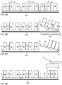
- FIGS 5A-5D illustrate a sequence of operations performed for grouping containers 40, e.g. in preparation for secondary packaging.
- the grouping serves to reduce or minimize the distance between the containers 40.
- the operations in FIGS 5A-5D may be performed in the wrapping machine 14 or the cardboard packing machine 15.
- the containers 40 are transported on a stationary transportation track 200 which comprises a tiled pattern of base elements (20 in FIG. 2A ).
- the first magnetic arrangements of the tiled base elements may be seen to collectively form a first magnetic arrangement of the transportation track 200, which is connected to receive the control signals S1-Sn from the control device (30 in FIG. 2A ).
- a trail of carriers 21 are propelled in the feed direction X along the track 200, and an upstream machine (e.g. the filling machine 10 in FIG. 1 ) has placed three containers 40 on each carrier 21 with a mutual spacing.
- an upstream machine e.g. the filling machine 10 in FIG. 1
- FIG. 5B when a leading carrier 21 arrives at a station 60 for secondary packaging, the trail of carriers 21 is intermittently stopped and the leading carrier 21 is tilted in the feed direction X.
- the tiling angle ⁇ pitch angle
- the carrier 21 may remain tilted until the containers 40 has slid into engagement with each other and form a compacted or condensed group of containers. If the carrier 21 comprises an active gripping mechanism (cf. FIGS 4A-4D ), this mechanism is operated to release the containers 40 on the carrier 21 before or while the carrier 21 is tilted. In FIG. 5D , the leading carrier 21 is returned to a horizontal position and the condensed group is processed for secondary packaging, in the illustrated example by being lifted by a gripper 61.
- an active gripping mechanism cf. FIGS 4A-4D
- the grouping of containers by tilting may replace conventional grouping devices which are structurally complicated, add cost, require maintenance, and take up space in the system 1, e.g. at the station 60 for secondary packaging. Further, the tilting may be performed anywhere along the track 200, giving flexibility to the system and reducing the need for structural modifications.
- FIGS 6A-6B illustrate a variant, in which the supporting surfaces 25 of a sequence of consecutive carriers 21 are tilted in unison to define a composite planar surface, so that the containers 40 on the tilted supporting surface are allowed to slide towards the front end of the leading carrier 21 and onto the stopper 50.
- This grouping is achieved irrespective of the number of containers on the respective carrier 21. As shown, grouping is possible even if each carrier 21 carries a single container 40.
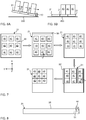
- FIG. 7 illustrates a two-dimensional pattern of spaced-apart containers 40 on a carrier 21.
- a first tilting causes the support surface 25 to be tilted in the feed dimension X so as to slide the containers 40 onto a first stopper 50, thereby forming spaced rows of abutting containers 40.
- a second tilting causes the support surface 25 to be tilted in the lateral dimension Y so as to slide the containers 40 onto a second stopper 50', thereby transforming the two-dimensional pattern of containers 40 into a condensed group.
- one-dimensional grouping may be performed by tilting the supporting surface 25 in the lateral dimension Y, by analogy with the second tilting in FIG. 7 .
- the stopper 50 may be separate from the carrier 21, as shown in FIGS 5-6 .
- the stopper may be an arm that is swung or translated into position whenever a tilting operation is to be performed for grouping.
- the stopper 50 is integrated into the carrier 21.
- the stopper 50 may be moveable in a direction perpendicular to the support surface 25 between a retraced state in which the stopper 50 is located level with or beneath the support surface 25, and a projecting state in which the stopper 50 projects from the support surface 25.
- An actuator 51 may be arranged in the carrier 21 to move the stopper 50. By analogy with FIG. 4C , the actuator 51 may set the stopper 50 in the projecting state based on a control signal from the control device 30, during or before the tilting of the support surface.
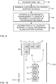
- step 91 one or more containers 40 are arranged on the support surface 25 of a carrier 21, which is located on the track 200.
- the container(s) 40 may or may not be filled with the food product at this stage.
- step 92 the active magnetic arrangement (in the track 200 or the carrier 21, depending on implementation) is operated to generate movement of the carrier 21 in the feed direction X along the track 200.
- step 93 the support surface 25 is intermittently tilted (by tilting the carrier 21 and/or the platform 26, depending on implementation) to slide the one or more containers 40 along the support surface 25.
- the method 90 may be executed based on control signals from the control device 30 in FIG. 2A .
- the tilting of the support surface 25 may not only be used to form a condensed group of containers 40, but may also be used for unloading the condensed group from the carrier 21 onto a receiving surface, e.g. a conventional conveyor or a table for pickup by a robot (cf. FIG. 1 ).
- a receiving surface e.g. a conventional conveyor or a table for pickup by a robot (cf. FIG. 1 ).
- the stopper 50 may be removed, to thereby allow the group of containers 40 to slide onto the receiving surface.
- the stopper 50 is omitted and grouping and unloading is performed jointly as the containers 40 are slid along the tilted support surface 25 onto the receiving surface.
- planar motor as described in the foregoing and implemented for transportation of containers enables additional improvements in the context of production of packaged food products.
- the respective carrier 21 is operable for movement in the XY plane.
- the carriers 21 may be moved in any direction on the track 200 and be arranged in any desirable pattern on the track 200, subject to the geometric limitations of the track 200.
- FIG. 10 illustrates an embodiment, in which the track 200 has a width in the lateral dimension Y that allows two or more carriers 21 to be arranged side by side in the lateral dimension Y. As shown, this enables grouping of carriers 21, and thus containers 40, in both the X dimension and the Y dimension.
- the grouping may be changed dynamically and adapted to the current production requirements. For example, as indicated in FIG. 10 , the grouping may performed at a station 60 for secondary packaging. It is realized that a compact arrangement of containers 40 is attained at the station 60 if there is a single container 40 on each carrier 21 and if the footprints of the container 40 and the carrier 21 are substantially similar or matching.
- FIG. 11 illustrates another use of XY motion control.
- a feed of carriers 21, each carrying any number of containers 40 is selectively diverted at a diversion location 70 onto either a first conveyor 300A or a second conveyor 300B.
- conventional belt drives 71 are arranged at the respective interface between the track 200 and the conveyor 300A, 300B to lift the container(s) 40 from the carrier 21 onto the conveyor 300A, 300B.
- the track 200 may extend at right angles from the diversion location 70, to allow the empty carriers 21 to be moved away for subsequent use in transporting containers 40 in the system.
- FIGS 10-11 may be seen to exemplify an apparatus for transporting containers 40 in a system for production of packaged food products, the apparatus comprising: a transportation track 200, and a plurality of carriers 21 for arrangement on the transportation track 200, the respective carrier 21 comprising a support surface 25 which is configured to carry one or more of the containers 40, wherein the transportation track 200 comprises a first magnetic arrangement, and the carrier 21 comprises a second magnetic arrangement, said apparatus further comprising a control device 30 which is configured to operate one of the first and second magnetic arrangements to generate a movement of the respective carrier 21 in each of a feed dimension X and a lateral dimension Y on the transportation track 200.
- a control device 30 which is configured to operate one of the first and second magnetic arrangements to generate a movement of the respective carrier 21 in each of a feed dimension X and a lateral dimension Y on the transportation track 200.
- the control device 30 is configured to move a predefined set of carriers 40 on the transportation track 200 to form a desired pattern in the feed dimension X and/or lateral dimension Y, e.g. a grouped pattern in which the carriers 21 are arranged side by side.
- the control device 30 is configured to selectively divert the respective carrier 21 from the transportation track 200, by moving the respective carrier 21 in both the feed dimension X and the lateral dimension Y, to a conveyor 300A, 300B so as to unload of the one or more containers 40 from the respective carrier 21 onto the conveyor 300A, 300B.
- the support surface 25 is operable for controlled rotation (yaw) in the XY plane on the transportation track 200.
- a rotation ⁇ may be performed at a station 60 for secondary packaging, e.g. to orient the container 40 with its front surface 40A in a specific direction.
- FIG. 12 may be seen to exemplify an apparatus for transporting containers 40 in a system for production of packaged food products, the apparatus comprising: a transportation track 200, and a plurality of carriers 21 for arrangement on the transportation track 200, the respective carrier 21 comprising a support surface 25 which is configured to carry one or more of the containers 40, wherein the transportation track 200 comprises a first magnetic arrangement, and the carrier 21 comprises a second magnetic arrangement, said apparatus further comprising a control device 30 which is configured to operate one of the first and second magnetic arrangements to generate a movement of the respective carrier 21 in at least a feed direction X on the transportation track 200.
- the control device 30 is further configured to rotate the support surface 25 of the respective carrier 21 around an axis C which is perpendicular to the support surface 25 of the carrier 21, e.g. to orient the one or more containers 40 on the support surface 25 in a predefined direction.
Landscapes
- Engineering & Computer Science (AREA)
- Mechanical Engineering (AREA)
- Specific Conveyance Elements (AREA)
Abstract
Description
- The invention generally relates to systems or plants for production of packaged food products.
- The ever-growing demand of packaged food products causes a need for food producers to make more frequent changes in their production. Such changes include changing the production flow between different machines in a plant for production of packaged food products. With the packaging lines traditionally being used, such changes may be both expensive and time consuming to implement since they generally involve manual reconfiguration of the mechanical structure of machines and conveyors within the production plant.
- Thus, there is a general need to facilitate changes in the production flow within plants for production of packaged food products.
- It is also a general need to simplify the mechanical structure of machines and conveyors within the production plant.
- It is an object of the invention to at least partly overcome one or more limitations of the prior art.
- One such object is to provide a technique that makes handling of containers simpler and more flexible within a system for production of packaged food products.
- One or more of these objects, as well as further objects that may appear from the description below, may be at least partly achieved by an apparatus for transporting containers, a method for transporting containers, and a computer-readable medium according to the independent claims, embodiments thereof being defined by the dependent claims.
- A first aspect of the invention is an apparatus for transporting containers in a system for production of packaged food products. The apparatus comprises a transportation track, and a plurality of carriers for arrangement on the transportation track, the respective carrier comprising a support surface which is configured to carry one or more of the containers. The transportation track comprises a first magnetic arrangement, and the respective carrier comprises a second magnetic arrangement. The apparatus further comprises a control device which is configured to operate one of the first and second magnetic arrangements generate a movement of the respective carrier on the transportation track. The control device is further configured to intermittently tilt the support surface of the respective carrier to slide the one or more containers along the support surface towards an end of the support surface.
- In one embodiment, the control device is configured to intermittently tilt the support surface to slide the one or more containers along the support surface onto a stopper located on or at the support surface.
- In one embodiment, the support surface is configured to carry a pair of mutually spaced containers during the movement of the respective carrier on the transportation track, and the control device is configured to intermittently tilt the support surface to slide the mutually spaced containers into contact with each other.
- In one embodiment, the control device is configured to tilt the support surfaces of two adjacent carriers on the transportation track in unison and with the support surfaces held level.
- In one embodiment, the control device is configured to intermittently tilt the support surface at a station for arranging a plurality of the containers in a secondary packaging.
- In one embodiment, the control device is configured to intermittently tilt the support surface in at least one of a feed direction and a lateral direction perpendicular to the feed direction.
- In one embodiment, the control device is configured to operate at least one of the first and second magnetic arrangements to tilt the respective carrier.
- In one embodiment, the respective carrier comprises a moveable platform that defines at least part of the support surface and a platform actuator for moving the platform in relation to the carrier, wherein the control device is configured to operate the platform actuator to tilt the support surface.
- In one embodiment, the carrier comprises a gripping mechanism for engaging the one or more containers on the support surface, and wherein the control device is configured to intermittently deactivate the gripping mechanism to release the container when the support surface is tilted.
- In one embodiment, the first magnetic arrangement comprises an array of coils, and the second magnetic arrangement comprises an array of magnets.
- In one embodiment, the control device is further configured to operate at least one of the first and second magnetic arrangements to levitate the respective carrier over the transportation track during the movement on the transportation track.
- A second aspect of the invention is a method of transporting containers in a system for production of packaged food products. The method comprises: arranging one or more of the containers on a support surface of a respective carrier on a transportation track; operating one of a first magnetic arrangement in the transportation track and a second magnetic arrangement in the respective carrier to move the respective carrier on the transportation track; and intermittently tilting the support surface to slide the one or more containers along the support surface towards an end of the support surface.
- Any one of the embodiments of the first aspect may be adapted and implemented as an embodiment of the second aspect.
- A third aspect of the invention is a computer-readable medium comprising computer instructions which, when executed by a processing device, cause the processing device to perform the method of the second aspects or any of its embodiments.
- Still other objectives, as well as features, aspects and advantages of the invention will appear from the following detailed description as well as from the drawings.
- Embodiments of the invention will now be described, by way of example, with reference to the accompanying schematic drawings.
-
FIG. 1 a perspective view of an example plant for production of packaged food products. -
FIG. 2A is an elevated side view of an apparatus for transportation of containers during production of packaged food products, andFIG. 2B is a perspective view of a carrier in the apparatus ofFIG. 2A . -
FIGS 3A-3F are elevated side views of embodiments of the carrier inFIG. 2B for enabling change of elevation, rotation and tilting of a container. -
FIGS 4A-4D are elevated side views of gripping mechanisms for holding a container on a carrier. -
FIGS 5A-5D illustrate, in elevated side view, a sequence of operations for one-dimensional grouping of containers. -
FIGS 6A-6B illustrate, in elevated side view, an alternative sequence of operations for one-dimensional grouping of containers. -
FIG. 7 illustrates, in top plan view, a sequence of operations for two-dimensional grouping of containers. -
FIG. 8 is an elevated side view of a carrier with integrated stopper. -
FIG. 9 is a flow chart of a container handling method in accordance with an embodiment. -
FIG. 10 illustrates, in top plan view, an embodiment for grouping of carriers. -
FIG. 11 illustrates in top plan view, an embodiment for diverting a feed of containers onto separate conveyors. -
FIG. 12 illustrates, in perspective view, an embodiment for orienting a container. - Embodiments of the present invention will now be described more fully hereinafter with reference to the accompanying drawings, in which some, but not all, embodiments of the invention are shown. Indeed, the invention may be embodied in many different forms and should not be construed as limited to the embodiments set forth herein; rather, these embodiments are provided so that this disclosure may satisfy applicable legal requirements.
- Also, it will be understood that, where possible, any of the advantages, features, functions, devices, and/or operational aspects of any of the embodiments of the present invention described and/or contemplated herein may be included in any of the other embodiments of the present invention described and/or contemplated herein, and/or vice versa. In addition, where possible, any terms expressed in the singular form herein are meant to also include the plural form and/or vice versa, unless explicitly stated otherwise. As used herein, "at least one" shall mean "one or more" and these phrases are intended to be interchangeable. Accordingly, the terms "a" and/or "an" shall mean "at least one" or "one or more", even though the phrase "one or more" or "at least one" is also used herein. As used herein, except where the context requires otherwise owing to express language or necessary implication, the word "comprise" or variations such as "comprises" or "comprising" is used in an inclusive sense, that is, to specify the presence of the stated features but not to preclude the presence or addition of further features in various embodiments of the invention. As used herein, the term "and/or" comprises any and all combinations of one or more of the associated listed items. As used herein, the term "food product" comprises any substance that can be used or prepared for use as food by humans or animals. Such food products include, without limitation, beverages, dairy products, sauces, oils, creams, custards, soups, purees, broths, vegetables, desserts, mayonnaise, wine, pet food, whey powder, etc.
- Like reference signs refer to like elements throughout.
-
FIG. 1 is a schematic overview of an exemplifying production plant orsystem 1 which is configured to produce packaged food products. The food products are packaged in sealed containers or packages, which may be at least partly made of a paperboard material or a plastic material. For example, the container may be a carton or a bottle, which are well-known in the art. In the illustrated example, thesystem 1 comprises a sequence ofmachines conveyors 11 for transporting packages from one machine to the next. A fillingmachine 10 is configured to fill a food product into containers and seal the container. Anaccumulator machine 12 is configured to, if necessary, accumulate packages produced by the fillingmachine 10. Astraw application machine 13 is configured to attach a straw to the respective container. A wrappingmachine 14 is configured to arrange the containers in groups and enclose each group of containers in wrapping material, e.g. stretch foil or shrink foil, to produce a wrappedcontainer group 17A. Acardboard packing machine 15 is configured to arrange groups of containers in cardboard trays orcardboard cartons 17B and optionally also apply a wrapping material. The wrapping material, cardboard trays and cardboard cartons are commonly denoted "secondary packaging" in the art. - Embodiments of the present invention start out from the insight that it would be advantageous to at least partly transport the containers within the
system 1 by use of magnetically suspended "planar motors". Such planar motors are known in the field of photolithography and semiconductor processing, where they are implemented to provide micrometer- or nanometer-scale positioning of wafers or the like in clean spaces where particles must be kept at a minimum. Magnetically suspended planar motors, also known as maglev motors, are operable with minimum generation of contaminating particles due to low friction. Although these motivations are not primary objectives in the field of packaged food products, the present inventors have realized, by insightful reasoning, that it is both advantageous and viable to implement such planar motors in systems for production of packaged food products. Examples of magnetically suspended planar motors for micrometer- or nanometer-scale positioning are given inUS6777833 ,US8686602 ,US6208045 ,US6259174 andUS5641054 . Further examples of magnetically suspended planar motors are found inWO2006/054243 ,WO2009/083889 , and the article "Electro-dynamic planar motor" by Compter et al., published in Proc. of Mechatronics 2002, University of Twente, 24-26 June 2002, pages 81-87. - The implementation of magnetically suspended planar motors in systems for production of packaged food products has the potential of reducing the need for external guides as well as mechanical bearings, which in turn leads to reduced wear and MTBF (Mean Time Between Failures). Ultimately, this results in reduced operating cost of the system. A magnetically suspended planar motor is effectively a direct drive mechanism, which enables dynamic control of position, velocity, acceleration and orientation (attitude) of a container or an array of containers. By proper implementation in the system, these properties may result in increased flexibility of production, e.g. with respect to changes in the format of the containers or changes in the required pattern of containers, e.g. for secondary packaging.
-
FIG. 2A illustrates an embodiment of a magnetically suspended planar motor for use in the system ofFIG. 1 . The planar motor comprises a stationary (fixed)base element 20 with a planar top surface, and amoveable carrier 21 which is arranged to overlie thebase element 20. As indicated inFIG. 2A ,identical base elements 20 may be tiled in an X dimension, and possibly in a Y dimension (not shown), to define an extended transportation surface. The transportation surface may form a transportation track in thesystem 1, e.g. to replace at least part of one or more of theconveyors 11 inFIG. 1 or to transport containers within any one of themachines FIG. 1. FIG. 2A includes an orthogonal XYZ coordinate system, in which the X dimension is parallel to the feed direction of such a transportation track, the Y dimension is a lateral dimension (orthogonal to the X dimension on the top surface of the base element 20), and the Z dimension is a levitation dimension (perpendicular to the top surface of the base element 20). As indicated schematically inFIG. 2A , the top surface of thecarrier 21 defines asupport surface 25 for carrying one or more containers in thesystem 1. - The
respective base element 20 comprises a first magnetic arrangement, and thecarrier 21 comprises a second magnetic arrangement. One of the magnetic arrangements is "active" and operable, when energized, to selectively generate a magnetic field that interacts with the other magnetic arrangement, which is passive, to move or propel thecarrier 21 in relation to thebase element 20, at least in the X dimension, and preferably also in the Y dimension. In one embodiment, the magnetic field is generated by selectively applying commutation currents to an array of coils in the active magnetic arrangement. The active magnetic arrangement may be installed in either of thebase element 20 and thecarrier 21. In a currently preferred embodiment, the active magnetic arrangement is located inbase element 20, to obviate the need to supply control signals and power signals to the movingcarrier 21. - Consequently, in the example of
FIG. 2A as well as the following examples, the first magnetic arrangement in thebase element 20 is active and comprises an array ofcoils 22 and associatedcircuitry 23 for providing and/or generating commutation currents for thecoils 22. The second magnetic arrangement in thecarrier 21 comprises an array ofmagnets 24 and thus passive. Acontrol device 30 is configured to generate control signals S1-Sn for thebase elements 20 to control the movement of thecarrier 21 on thebase elements 20. The control signals S1-Sn may comprise the above-mentioned commutation signals for thecoils 22 in therespective base element 21. Alternatively, if thecircuitry 23 is configured to generate the commutation signals, thecontrol device 30 may supply power to therespective base element 20 in addition to the control signals S1-Sn, which may designate a desired position or trajectory of thecarrier 21 on therespective base element 20. As indicated inFIG. 2A , thecontrol device 30 may operate the planar motor to levitate thecarrier 21, by causing thecoils 22 to generate a magnetic field that arranges thecarrier 21 with a small spacing or gap between the bottom surface of thecarrier 21 and the top surface of therespective base element 20. - The
control device 30 may be further configured to generate control signals (not shown) for controlling and synchronizing operation of thesystem 1. - In the illustrated embodiment, the
control device 30 comprises aprocessor 31 andcomputer memory 32. Theprocessor 30 may e.g. include one or more of a CPU ("Central Processing Unit"), a DSP ("Digital Signal Processor"), a microprocessor, a microcontroller, an ASIC ("Application-Specific Integrated Circuit"), a combination of discrete analog and/or digital components, or some other programmable logical device, such as an FPGA ("Field Programmable Gate Array"). A control program comprising computer instructions is stored in thememory 32 and executed by theprocessor 31 to generate the control signals S1 for the planar motor. The control program may be supplied to thecontrol device 30 on a computer-readable medium, which may be a tangible (non-transitory) product (e.g. magnetic medium, optical disk, read-only memory, flash memory, etc) or a propagating signal. -
FIG. 2B illustrates an embodiment of the planar motor, in which thecarrier 21 is independently controllable for movement in four degrees of freedom (DOF), specifically the X dimension, the Y dimension, the Z dimension and for rotation ω around an axis C which is perpendicular to thesupport surface 25 of thecarrier 21. The rotation axis C may, but need not, be located at the geometric center ofcarrier 21. -
FIG. 3A illustrates an embodiment of a planar motor, in which a change in the levitation of thecarrier 21, in the Z dimension, may be effected by modifying the magnetic field generated by the first magnetic arrangement in thebase element 20. Thereby, thesupport surface 25 may be controllably moved away from and towards thebase element 21. -
FIG. 3B illustrates an embodiment, in which amoveable platform 26 is installed in thecarrier 21 to define at least part of thesupport surface 25. Aplatform actuator 27 is arranged in thecarrier 21 to translate theplatform 27 away from and towards thecarrier 21. This embodiment may relax the requirements on the first and/or second magnetic arrangements. Theactuator 27 may be any form of motor, e.g. electric, pneumatic, or hydraulic, which may be controlled by a control signal generated by thecontrol device 30 and transmitted by wire or wirelessly to thecarrier 21. In an alternative, theactuator 27 may be controlled by the magnetic field generated by the first magnetic arrangement in thebase element 20. In a further alternative, the actuator is omitted and the movement of theplatform 26 is controlled by the magnetic field generated by the first magnetic arrangement in thebase element 20. -
FIG. 3C illustrates an embodiment of a planar motor, in which the rotation ω of thecarrier 21 around the axis C may be effected by modifying the magnetic field generated by the first magnetic arrangement in thebase element 20. Thereby, thesupport surface 25 may be controllably rotated with respect to an arbitrary reference direction in the XY plane. -
FIG. 3D illustrates an embodiment, in which arotatable platform 26 is installed in thecarrier 21 to define at least part of thesupport surface 25. Controlled rotation of theplatform 26 may be effected in analogy with the embodiment inFIG. 3B , e.g. byactuator 27. -
FIG. 3E illustrates an embodiment of a planar motor, in which a change in tilt angle α of thecarrier 21, e.g. in the X dimension or the Y dimension, may be effected by modifying the magnetic field generated by the first magnetic arrangement in thebase element 20. Thereby, thesupport surface 25 may be controllably tilted from a horizontal plane. -
FIG. 3F illustrates an embodiment, in which amoveable platform 26 is installed in thecarrier 21 to define at least part of thesupport surface 25. Themoveable platform 26 is arranged for tilting in at least one direction. Controlled tilting of theplatform 26 may be effected in analogy with the embodiment inFIG. 3B , e.g. byactuator 27. - It should be understood that two or more of the embodiments in
FIGS 3A-3F may be combined to provide any desirable number of DOF. For example, the planar motor as described herein may exhibit up to 6 independent DOF, including movement in the X, Y and Z dimensions, rotation around the axis C (also known as "yaw"), tilting in the X dimension (also known as "pitch") and tilting in the Y dimension (also known as "roll"). -
FIGS 4A-4D show examples of gripping mechanisms for holding one or more containers (not shown) onto thesupport surface 25. InFIG. 4A , the gripping mechanism comprises one ormore electromagnets 28A for generating a magnetic field to attract the bottom surface of the respective container which, in this example, comprises a ferromagnetic material. InFIG. 4B , the gripping mechanism comprises aconduit 28B that opens into thesupport surface 25 and is connected to a source (not shown) for generating a sub-atmospheric pressure. InFIG. 4C , the gripping mechanism comprises one ormore projection elements 28C (two shown), which are moveable in a direction perpendicular to thesupport surface 25 between a retraced state in which therespective projection element 28C is located level with or beneath thesupport surface 25, and a projecting state in which therespective projection element 28C projects from thesupport surface 25 to define a containment region that mates with one or more containers. InFIG. 4D , the gripping mechanism comprisesprojection elements 28D (two shown), which are moveable in a direction parallel to thesupport surface 25 to be pressed against one or more containers on thesupport surface 25. In one example, theprojection elements 28D may be arranged and configured similar to jaws of a mechanical chuck. As indicated inFIGS 4C and 4D , one or more actuators 29 (two shown) may be arranged in thecarrier 21 to move theprojection elements FIGS 4A-4D are "active", in the sense that they may be selectively operated to switch between engaging and releasing the container(s) on thesupport surface 25, e.g. based on a control signal from the control device 30 (FIG. 1 ). - In an alternative, the
respective carrier 21 comprises a passive gripping mechanism, e.g. one or more fixed projections (cf.FIG. 4C ), one or more permanent magnets (cf.FIG. 4A ), or a high friction surface structure. It is also conceivable that the gripping mechanism is omitted. - The inventors have realized that the tilting function as exemplified in
FIGS 3C-3D may provide distinct advantages when used in a system for production of packaged food products. Related embodiments will be described with reference toFIGS 5-9 . -
FIGS 5A-5D illustrate a sequence of operations performed for groupingcontainers 40, e.g. in preparation for secondary packaging. The grouping serves to reduce or minimize the distance between thecontainers 40. With reference toFIG. 1 , the operations inFIGS 5A-5D may be performed in the wrappingmachine 14 or thecardboard packing machine 15. Thecontainers 40 are transported on astationary transportation track 200 which comprises a tiled pattern of base elements (20 inFIG. 2A ). The first magnetic arrangements of the tiled base elements may be seen to collectively form a first magnetic arrangement of thetransportation track 200, which is connected to receive the control signals S1-Sn from the control device (30 inFIG. 2A ). InFIG. 5A , a trail ofcarriers 21 are propelled in the feed direction X along thetrack 200, and an upstream machine (e.g. the fillingmachine 10 inFIG. 1 ) has placed threecontainers 40 on eachcarrier 21 with a mutual spacing. InFIG. 5B , when a leadingcarrier 21 arrives at astation 60 for secondary packaging, the trail ofcarriers 21 is intermittently stopped and the leadingcarrier 21 is tilted in the feed direction X. The tiling angle α (pitch angle) is set so that thecontainers 40, by action of gravity, overcome the friction on thesupport surface 25 and slide towards the front end of thecarrier 21 onto astopper 50. As shown inFIG. 5C , thecarrier 21 may remain tilted until thecontainers 40 has slid into engagement with each other and form a compacted or condensed group of containers. If thecarrier 21 comprises an active gripping mechanism (cf.FIGS 4A-4D ), this mechanism is operated to release thecontainers 40 on thecarrier 21 before or while thecarrier 21 is tilted. InFIG. 5D , the leadingcarrier 21 is returned to a horizontal position and the condensed group is processed for secondary packaging, in the illustrated example by being lifted by agripper 61. - The grouping of containers by tilting may replace conventional grouping devices which are structurally complicated, add cost, require maintenance, and take up space in the
system 1, e.g. at thestation 60 for secondary packaging. Further, the tilting may be performed anywhere along thetrack 200, giving flexibility to the system and reducing the need for structural modifications. -
FIGS 6A-6B illustrate a variant, in which the supportingsurfaces 25 of a sequence ofconsecutive carriers 21 are tilted in unison to define a composite planar surface, so that thecontainers 40 on the tilted supporting surface are allowed to slide towards the front end of the leadingcarrier 21 and onto thestopper 50. This grouping is achieved irrespective of the number of containers on therespective carrier 21. As shown, grouping is possible even if eachcarrier 21 carries asingle container 40. - The grouping by tilting is not limited to one-dimensional grouping as shown in
FIGS 5-6 .FIG. 7 illustrates a two-dimensional pattern of spaced-apartcontainers 40 on acarrier 21. A first tilting causes thesupport surface 25 to be tilted in the feed dimension X so as to slide thecontainers 40 onto afirst stopper 50, thereby forming spaced rows of abuttingcontainers 40. After returning thesupport surface 25 to horizontal, a second tilting causes thesupport surface 25 to be tilted in the lateral dimension Y so as to slide thecontainers 40 onto a second stopper 50', thereby transforming the two-dimensional pattern ofcontainers 40 into a condensed group. - It is also to be realized that one-dimensional grouping may be performed by tilting the supporting
surface 25 in the lateral dimension Y, by analogy with the second tilting inFIG. 7 . - The
stopper 50 may be separate from thecarrier 21, as shown inFIGS 5-6 . For example, the stopper may be an arm that is swung or translated into position whenever a tilting operation is to be performed for grouping. Alternatively, as exemplified inFIG. 8 , thestopper 50 is integrated into thecarrier 21. Thestopper 50 may be moveable in a direction perpendicular to thesupport surface 25 between a retraced state in which thestopper 50 is located level with or beneath thesupport surface 25, and a projecting state in which thestopper 50 projects from thesupport surface 25. Anactuator 51 may be arranged in thecarrier 21 to move thestopper 50. By analogy withFIG. 4C , theactuator 51 may set thestopper 50 in the projecting state based on a control signal from thecontrol device 30, during or before the tilting of the support surface. - The sequence of events described above with reference to
FIGS 5-7 may correspond to ahandling method 90 shown inFIG. 9 . Instep 91, one ormore containers 40 are arranged on thesupport surface 25 of acarrier 21, which is located on thetrack 200. The container(s) 40 may or may not be filled with the food product at this stage. Instep 92, the active magnetic arrangement (in thetrack 200 or thecarrier 21, depending on implementation) is operated to generate movement of thecarrier 21 in the feed direction X along thetrack 200. Instep 93, thesupport surface 25 is intermittently tilted (by tilting thecarrier 21 and/or theplatform 26, depending on implementation) to slide the one ormore containers 40 along thesupport surface 25. Themethod 90 may be executed based on control signals from thecontrol device 30 inFIG. 2A . - The tilting of the
support surface 25 may not only be used to form a condensed group ofcontainers 40, but may also be used for unloading the condensed group from thecarrier 21 onto a receiving surface, e.g. a conventional conveyor or a table for pickup by a robot (cf.FIG. 1 ). For example, inFIG. 5C and assuming that the receiving surface is located to the right oftrack 200, thestopper 50 may be removed, to thereby allow the group ofcontainers 40 to slide onto the receiving surface. In another variant, thestopper 50 is omitted and grouping and unloading is performed jointly as thecontainers 40 are slid along the tiltedsupport surface 25 onto the receiving surface. - The planar motor as described in the foregoing and implemented for transportation of containers enables additional improvements in the context of production of packaged food products.
- By proper configuration of the first and second magnetic arrangements in the
track 200 and thecarrier 21, therespective carrier 21 is operable for movement in the XY plane. Thus, by simply modifying the control program of thecontrol device 30, and without the need for structural modifications, thecarriers 21 may be moved in any direction on thetrack 200 and be arranged in any desirable pattern on thetrack 200, subject to the geometric limitations of thetrack 200. -
FIG. 10 illustrates an embodiment, in which thetrack 200 has a width in the lateral dimension Y that allows two ormore carriers 21 to be arranged side by side in the lateral dimension Y. As shown, this enables grouping ofcarriers 21, and thuscontainers 40, in both the X dimension and the Y dimension. The grouping may be changed dynamically and adapted to the current production requirements. For example, as indicated inFIG. 10 , the grouping may performed at astation 60 for secondary packaging. It is realized that a compact arrangement ofcontainers 40 is attained at thestation 60 if there is asingle container 40 on eachcarrier 21 and if the footprints of thecontainer 40 and thecarrier 21 are substantially similar or matching. -
FIG. 11 illustrates another use of XY motion control. A feed ofcarriers 21, each carrying any number ofcontainers 40, is selectively diverted at adiversion location 70 onto either afirst conveyor 300A or asecond conveyor 300B. In the illustrated example, conventional belt drives 71 are arranged at the respective interface between thetrack 200 and theconveyor carrier 21 onto theconveyor track 200 may extend at right angles from thediversion location 70, to allow theempty carriers 21 to be moved away for subsequent use in transportingcontainers 40 in the system. -
FIGS 10-11 may be seen to exemplify an apparatus for transportingcontainers 40 in a system for production of packaged food products, the apparatus comprising: atransportation track 200, and a plurality ofcarriers 21 for arrangement on thetransportation track 200, therespective carrier 21 comprising asupport surface 25 which is configured to carry one or more of thecontainers 40, wherein thetransportation track 200 comprises a first magnetic arrangement, and thecarrier 21 comprises a second magnetic arrangement, said apparatus further comprising acontrol device 30 which is configured to operate one of the first and second magnetic arrangements to generate a movement of therespective carrier 21 in each of a feed dimension X and a lateral dimension Y on thetransportation track 200. In the embodiment ofFIG. 10 , thecontrol device 30 is configured to move a predefined set ofcarriers 40 on thetransportation track 200 to form a desired pattern in the feed dimension X and/or lateral dimension Y, e.g. a grouped pattern in which thecarriers 21 are arranged side by side. In the embodiment ofFIG. 11 , thecontrol device 30 is configured to selectively divert therespective carrier 21 from thetransportation track 200, by moving therespective carrier 21 in both the feed dimension X and the lateral dimension Y, to aconveyor more containers 40 from therespective carrier 21 onto theconveyor - By proper configuration of the first and second magnetic arrangements in the
track 200 and thecarrier 21, and/or by provision of aplatform 26 as exemplified inFIG. 3D , thesupport surface 25 is operable for controlled rotation (yaw) in the XY plane on thetransportation track 200. Thus, by simply modifying the control program of thecontrol device 30, and without the need for structural modifications, the rotation of thecontainers 40 may be changed dynamically and adapted to the current production requirements. For example, as indicated inFIG. 12 , a rotation ω may performed at astation 60 for secondary packaging, e.g. to orient thecontainer 40 with itsfront surface 40A in a specific direction. -
FIG. 12 may be seen to exemplify an apparatus for transportingcontainers 40 in a system for production of packaged food products, the apparatus comprising: atransportation track 200, and a plurality ofcarriers 21 for arrangement on thetransportation track 200, therespective carrier 21 comprising asupport surface 25 which is configured to carry one or more of thecontainers 40, wherein thetransportation track 200 comprises a first magnetic arrangement, and thecarrier 21 comprises a second magnetic arrangement, said apparatus further comprising acontrol device 30 which is configured to operate one of the first and second magnetic arrangements to generate a movement of therespective carrier 21 in at least a feed direction X on the transportation track 200.Thecontrol device 30 is further configured to rotate thesupport surface 25 of therespective carrier 21 around an axis C which is perpendicular to thesupport surface 25 of thecarrier 21, e.g. to orient the one ormore containers 40 on thesupport surface 25 in a predefined direction.
Claims (13)
- An apparatus for transporting containers (40) in a system for production of packaged food products, said apparatus comprising:a transportation track (200), anda plurality of carriers (21) for arrangement on the transportation track (200), the respective carrier (21) comprising a support surface (25) which is configured to carry one or more of the containers (40),wherein the transportation track (200) comprises a first magnetic arrangement (22, 23), and the respective carrier (21) comprises a second magnetic arrangement (24),said apparatus further comprising a control device (30) which is configured to operate one of the first and second magnetic arrangements (22, 23; 24) generate a movement of the respective carrier (21) on the transportation track (200),wherein the control device (30) is further configured to intermittently tilt the support surface (25) of the respective carrier (21) to slide the one or more containers (40) along the support surface (25) towards an end of the support surface (25).
- The apparatus of claim 1, wherein the control device (30) is configured to intermittently tilt the support surface (25) to slide the one or more containers (40) along the support surface (25) onto a stopper (50) located on or at the support surface (25).
- The apparatus of claim 1 or 2, wherein the support surface (25) is configured to carry a pair of mutually spaced containers (40) during the movement of the respective carrier (21) on the transportation track (200), and wherein the control device (30) is configured to intermittently tilt the support surface (25) to slide the mutually spaced containers (40) into contact with each other.
- The apparatus of any preceding claim, wherein the control device (30) is configured to tilt the support surfaces (25) of two adjacent carriers (21) on the transportation track (200) in unison and with the support surfaces (25) held level.
- The apparatus of any preceding claim, wherein the control device (30) is configured to intermittently tilt the support surface (25) at a station (60) for arranging a plurality of the containers (40) in a secondary packaging.
- The apparatus of any preceding claim, wherein the control device (30) is configured to intermittently tilt the support surface (25) in at least one of a feed direction (X) and a lateral direction (Y) perpendicular to the feed direction (X).
- The apparatus of any preceding claim, wherein the control device (30) is configured to operate at least one of the first and second magnetic arrangements (22, 23; 24) to tilt the respective carrier (21).
- The apparatus of any preceding claim, wherein the respective carrier (21) comprises a moveable platform (26) that defines at least part of the support surface (25) and a platform actuator (27) for moving the platform (26) in relation to the carrier (21), wherein the control device (30) is configured to operate the platform actuator (27) to tilt the support surface (25).
- The apparatus of any preceding claim, wherein the carrier (21) comprises a gripping mechanism (28A; 28B; 28C; 28D) for engaging the one or more containers (40) on the support surface (25), and wherein the control device (30) is configured to intermittently deactivate the gripping mechanism (28A; 28B; 28C; 28D) to release the container (40) when the support surface (25) is tilted.
- The apparatus of any preceding claim, wherein the first magnetic arrangement (22, 23) comprises an array of coils (22), and the second magnetic arrangement comprises an array of magnets (24).
- The apparatus of any preceding claim, wherein the control device (30) is further configured to operate at least one of the first and second magnetic arrangements (22, 23; 24) to levitate the respective carrier (21) over the transportation track (200) during the movement on the transportation track (200).
- A method of transporting containers (40) in a system for production of packaged food products, said method comprising:arranging (91) one or more of the containers (40) on a support surface (25) of a respective carrier (21) on a transportation track (200),operating (92) one of a first magnetic arrangement (22, 23) in the transportation track (200) and a second magnetic arrangement (24) in the respective carrier (21) to move the respective carrier (21) on the transportation track (200), andintermittently tilting (93) the support surface (25) to slide the one or more containers (40) along the support surface (25) towards an end of the support surface (25).
- A computer readable medium comprising computer instructions which, when executed by a processing device (31), causes the processing device (31) to perform the method according to claim 12.
Priority Applications (1)
| Application Number | Priority Date | Filing Date | Title |
|---|---|---|---|
| EP18208124.0A EP3656707B1 (en) | 2018-11-23 | 2018-11-23 | Handling of containers in a system for production of packaged food products |
Applications Claiming Priority (1)
| Application Number | Priority Date | Filing Date | Title |
|---|---|---|---|
| EP18208124.0A EP3656707B1 (en) | 2018-11-23 | 2018-11-23 | Handling of containers in a system for production of packaged food products |
Publications (2)
| Publication Number | Publication Date |
|---|---|
| EP3656707A1 true EP3656707A1 (en) | 2020-05-27 |
| EP3656707B1 EP3656707B1 (en) | 2023-03-15 |
Family
ID=64456885
Family Applications (1)
| Application Number | Title | Priority Date | Filing Date |
|---|---|---|---|
| EP18208124.0A Active EP3656707B1 (en) | 2018-11-23 | 2018-11-23 | Handling of containers in a system for production of packaged food products |
Country Status (1)
| Country | Link |
|---|---|
| EP (1) | EP3656707B1 (en) |
Cited By (18)
| Publication number | Priority date | Publication date | Assignee | Title |
|---|---|---|---|---|
| DE102020120295A1 (en) | 2020-07-31 | 2022-02-03 | Krones Aktiengesellschaft | Device for equipping containers |
| DE102020120279A1 (en) | 2020-07-31 | 2022-02-03 | Krones Aktiengesellschaft | container treatment plant |
| EP3929115A3 (en) * | 2020-06-22 | 2022-02-23 | Krones Ag | Method and device for buffering containers |
| IT202100006770A1 (en) * | 2021-03-22 | 2022-09-22 | Ima Spa | VIBRATORY EQUIPMENT AND RELATED PROCEDURE FOR CONVEYING OBJECTS. |
| DE102022105749A1 (en) | 2022-03-11 | 2023-09-14 | Krones Aktiengesellschaft | Beverage bottling plant using planar motor drones and/or different conveyor modules/planar motor movers, use of a drone on/in a beverage bottling plant and method for operating a beverage bottling plant |
| EP4249412A1 (en) * | 2022-03-23 | 2023-09-27 | Syntegon Technology GmbH | Transport system and method for transporting a plurality of containers |
| CN117002930A (en) * | 2022-05-03 | 2023-11-07 | 星德科技术有限公司 | Flat transport device and method of operating a flat transport device |
| WO2023217763A1 (en) * | 2022-05-11 | 2023-11-16 | Beckhoff Automation Gmbh | Method for controlling a planar drive system, rotor, stator unit, and planar drive system |
| EP4253289A3 (en) * | 2022-03-31 | 2024-01-17 | CT PACK S.r.l. | Apparatus and method for conveying articles and plant and method for packaging said articles |
| EP4324773A1 (en) * | 2022-08-19 | 2024-02-21 | Pacraft Co., Ltd. | Processing system |
| DE102022122688A1 (en) | 2022-09-07 | 2024-03-07 | Krones Aktiengesellschaft | System and method for transporting and manipulating articles |
| IT202200019107A1 (en) * | 2022-09-19 | 2024-03-19 | I M A Industria Macch Automatiche S P A In Sigla Ima S P A | EQUIPMENT FOR TRANSPORTING OBJECTS. |
| US20240174449A1 (en) * | 2021-03-03 | 2024-05-30 | Jürgen Bialy | Conveyor system for conveying goods to be conveyed |
| IT202300002217A1 (en) * | 2023-02-09 | 2024-08-09 | Tetra Laval Holdings & Finance | APPARATUS FOR GROUPING PACKAGES, PACKAGING PLANT, METHOD FOR GROUPING PACKAGES |
| IT202300012507A1 (en) * | 2023-06-16 | 2024-12-16 | Fmt S R L | APPARATUS FOR THE FORMATION OF A LAYER OF PRODUCTS AND RELATED METHOD |
| IT202300012972A1 (en) * | 2023-06-22 | 2024-12-22 | Tetra Laval Holdings & Finance | DEVICE FOR TRANSPORTING PACKAGES, IN PARTICULAR PRODUCTS IN A PACKAGING MACHINE, UNIT FOR PROCESSING PACKAGES WITH SAID TRANSPORTING DEVICE AND METHOD FOR OPERATION OF SAID TRANSPORTING DEVICE |
| US12415684B2 (en) | 2021-03-03 | 2025-09-16 | Provisur Technologies, Inc. | Belt conveyor for conveying foodstuff products |
| US12466100B2 (en) | 2021-03-03 | 2025-11-11 | Provisur Technologies, Inc. | Food-processing system |
Citations (16)
| Publication number | Priority date | Publication date | Assignee | Title |
|---|---|---|---|---|
| JPS5122278U (en) * | 1974-08-03 | 1976-02-18 | ||
| JPS5257675A (en) * | 1975-11-05 | 1977-05-12 | Mitsubishi Heavy Ind Ltd | Tiltable put aside apparatus for conveying articles |
| JPS63164077U (en) * | 1986-11-26 | 1988-10-26 | ||
| US5641054A (en) | 1992-07-07 | 1997-06-24 | Ebara Corporation | Magnetic levitation conveyor apparatus |
| DE19817255C1 (en) * | 1998-04-19 | 1999-09-09 | Wolf Montage Automationsanlage | Carrier for workpiece transport e.g. for transporting books or medicines between storage and dispatch locations |
| WO2000051921A1 (en) * | 1999-03-05 | 2000-09-08 | Pri Automation, Inc. | Material handling and transport system and process |
| US6208045B1 (en) | 1998-11-16 | 2001-03-27 | Nikon Corporation | Electric motors and positioning devices having moving magnet arrays and six degrees of freedom |
| US6259174B1 (en) | 1997-08-21 | 2001-07-10 | Nikon Corporation | Positioning apparatus, drive unit and exposure apparatus incorporating the positioning apparatus |
| US6777833B1 (en) | 2001-12-17 | 2004-08-17 | Ultratech Stepper, Inc. | Magnetic levitation stage apparatus and method |
| WO2006054243A2 (en) | 2004-11-19 | 2006-05-26 | Koninklijke Philips Electronics N.V. | Method for controlling an electric motor, control unit and electric motor |
| WO2009083889A1 (en) | 2007-12-28 | 2009-07-09 | Koninklijke Philips Electronics N.V. | Contactless lifting of an object by an inverted planar motor |
| US8686602B2 (en) | 2010-12-03 | 2014-04-01 | Sri International | Levitated micro-manipulator system |
| DE102014117150A1 (en) * | 2014-11-24 | 2016-05-25 | Beckhoff Automation Gmbh | XY table for a linear transport system |
| DE102014119351A1 (en) * | 2014-12-22 | 2016-06-23 | Weber Maschinenbau Gmbh Breidenbach | DEVICE FOR MOVING OBJECTS |
| DE102016109435A1 (en) * | 2016-05-23 | 2017-11-23 | Weber Maschinenbau Gmbh Breidenbach | Transport movers and device with transport movers |
| DE102016122462A1 (en) * | 2016-11-22 | 2018-05-24 | Krones Ag | Device for sorting and conveying container closures |
-
2018
- 2018-11-23 EP EP18208124.0A patent/EP3656707B1/en active Active
Patent Citations (16)
| Publication number | Priority date | Publication date | Assignee | Title |
|---|---|---|---|---|
| JPS5122278U (en) * | 1974-08-03 | 1976-02-18 | ||
| JPS5257675A (en) * | 1975-11-05 | 1977-05-12 | Mitsubishi Heavy Ind Ltd | Tiltable put aside apparatus for conveying articles |
| JPS63164077U (en) * | 1986-11-26 | 1988-10-26 | ||
| US5641054A (en) | 1992-07-07 | 1997-06-24 | Ebara Corporation | Magnetic levitation conveyor apparatus |
| US6259174B1 (en) | 1997-08-21 | 2001-07-10 | Nikon Corporation | Positioning apparatus, drive unit and exposure apparatus incorporating the positioning apparatus |
| DE19817255C1 (en) * | 1998-04-19 | 1999-09-09 | Wolf Montage Automationsanlage | Carrier for workpiece transport e.g. for transporting books or medicines between storage and dispatch locations |
| US6208045B1 (en) | 1998-11-16 | 2001-03-27 | Nikon Corporation | Electric motors and positioning devices having moving magnet arrays and six degrees of freedom |
| WO2000051921A1 (en) * | 1999-03-05 | 2000-09-08 | Pri Automation, Inc. | Material handling and transport system and process |
| US6777833B1 (en) | 2001-12-17 | 2004-08-17 | Ultratech Stepper, Inc. | Magnetic levitation stage apparatus and method |
| WO2006054243A2 (en) | 2004-11-19 | 2006-05-26 | Koninklijke Philips Electronics N.V. | Method for controlling an electric motor, control unit and electric motor |
| WO2009083889A1 (en) | 2007-12-28 | 2009-07-09 | Koninklijke Philips Electronics N.V. | Contactless lifting of an object by an inverted planar motor |
| US8686602B2 (en) | 2010-12-03 | 2014-04-01 | Sri International | Levitated micro-manipulator system |
| DE102014117150A1 (en) * | 2014-11-24 | 2016-05-25 | Beckhoff Automation Gmbh | XY table for a linear transport system |
| DE102014119351A1 (en) * | 2014-12-22 | 2016-06-23 | Weber Maschinenbau Gmbh Breidenbach | DEVICE FOR MOVING OBJECTS |
| DE102016109435A1 (en) * | 2016-05-23 | 2017-11-23 | Weber Maschinenbau Gmbh Breidenbach | Transport movers and device with transport movers |
| DE102016122462A1 (en) * | 2016-11-22 | 2018-05-24 | Krones Ag | Device for sorting and conveying container closures |
Non-Patent Citations (1)
| Title |
|---|
| COMPTER ET AL.: "Proc. of Mechatronics 2002", 24 June 2002, UNIVERSITY OF TWENTE, article "Electro-dynamic planar motor", pages: 81 - 87 |
Cited By (32)
| Publication number | Priority date | Publication date | Assignee | Title |
|---|---|---|---|---|
| EP3929115A3 (en) * | 2020-06-22 | 2022-02-23 | Krones Ag | Method and device for buffering containers |
| US11498772B2 (en) | 2020-06-22 | 2022-11-15 | Krones Ag | Method and device for buffering containers |
| US12492034B2 (en) | 2020-07-31 | 2025-12-09 | Krones Ag | Device for equipping containers |
| DE102020120279A1 (en) | 2020-07-31 | 2022-02-03 | Krones Aktiengesellschaft | container treatment plant |
| US11809167B2 (en) | 2020-07-31 | 2023-11-07 | Krones Ag | Container processing system |
| DE102020120295A1 (en) | 2020-07-31 | 2022-02-03 | Krones Aktiengesellschaft | Device for equipping containers |
| US20240174449A1 (en) * | 2021-03-03 | 2024-05-30 | Jürgen Bialy | Conveyor system for conveying goods to be conveyed |
| US12415684B2 (en) | 2021-03-03 | 2025-09-16 | Provisur Technologies, Inc. | Belt conveyor for conveying foodstuff products |
| US12466100B2 (en) | 2021-03-03 | 2025-11-11 | Provisur Technologies, Inc. | Food-processing system |
| IT202100006770A1 (en) * | 2021-03-22 | 2022-09-22 | Ima Spa | VIBRATORY EQUIPMENT AND RELATED PROCEDURE FOR CONVEYING OBJECTS. |
| WO2022201207A1 (en) * | 2021-03-22 | 2022-09-29 | I.M.A. Industria Macchine Automatiche S.P.A. | Vibrating apparatus and corresponding method for conveying objects |
| DE102022105749A1 (en) | 2022-03-11 | 2023-09-14 | Krones Aktiengesellschaft | Beverage bottling plant using planar motor drones and/or different conveyor modules/planar motor movers, use of a drone on/in a beverage bottling plant and method for operating a beverage bottling plant |
| US12145809B2 (en) | 2022-03-23 | 2024-11-19 | Syntegon Technology Gmbh | Transport system and method for transporting a plurality of containers |
| EP4249412A1 (en) * | 2022-03-23 | 2023-09-27 | Syntegon Technology GmbH | Transport system and method for transporting a plurality of containers |
| EP4253289A3 (en) * | 2022-03-31 | 2024-01-17 | CT PACK S.r.l. | Apparatus and method for conveying articles and plant and method for packaging said articles |
| US12358736B2 (en) | 2022-03-31 | 2025-07-15 | Ct Pack S.R.L. | Apparatus and method for conveying articles and plant and method for packaging said articles |
| EP4289772A1 (en) * | 2022-05-03 | 2023-12-13 | Syntegon Technology GmbH | Planar transport device and method for operating a planar transport device |
| CN117002930A (en) * | 2022-05-03 | 2023-11-07 | 星德科技术有限公司 | Flat transport device and method of operating a flat transport device |
| WO2023217763A1 (en) * | 2022-05-11 | 2023-11-16 | Beckhoff Automation Gmbh | Method for controlling a planar drive system, rotor, stator unit, and planar drive system |
| EP4324773A1 (en) * | 2022-08-19 | 2024-02-21 | Pacraft Co., Ltd. | Processing system |
| JP2024027985A (en) * | 2022-08-19 | 2024-03-01 | Pacraft株式会社 | processing system |
| US12371281B2 (en) | 2022-08-19 | 2025-07-29 | PACRAFT Co., Ltd. | Processing system |
| WO2024052043A1 (en) | 2022-09-07 | 2024-03-14 | Krones Aktiengesellschaft | System and method for transporting and handling articles |
| DE102022122688A1 (en) | 2022-09-07 | 2024-03-07 | Krones Aktiengesellschaft | System and method for transporting and manipulating articles |
| WO2024062506A1 (en) * | 2022-09-19 | 2024-03-28 | I.M.A. Industria Macchine Automatiche S.P.A. | Apparatus for transporting objects |
| IT202200019107A1 (en) * | 2022-09-19 | 2024-03-19 | I M A Industria Macch Automatiche S P A In Sigla Ima S P A | EQUIPMENT FOR TRANSPORTING OBJECTS. |
| WO2024165374A1 (en) * | 2023-02-09 | 2024-08-15 | Tetra Laval Holdings & Finance S.A. | Grouping apparatus, packaging plant, method for grouping packages |
| EP4414298A1 (en) * | 2023-02-09 | 2024-08-14 | Tetra Laval Holdings & Finance S.A. | Grouping apparatus, packaging plant, method for grouping packages |
| IT202300002217A1 (en) * | 2023-02-09 | 2024-08-09 | Tetra Laval Holdings & Finance | APPARATUS FOR GROUPING PACKAGES, PACKAGING PLANT, METHOD FOR GROUPING PACKAGES |
| IT202300012507A1 (en) * | 2023-06-16 | 2024-12-16 | Fmt S R L | APPARATUS FOR THE FORMATION OF A LAYER OF PRODUCTS AND RELATED METHOD |
| EP4477585A1 (en) * | 2023-06-16 | 2024-12-18 | FMT S.r.l. | An apparatus for forming a layer of products and its method |
| IT202300012972A1 (en) * | 2023-06-22 | 2024-12-22 | Tetra Laval Holdings & Finance | DEVICE FOR TRANSPORTING PACKAGES, IN PARTICULAR PRODUCTS IN A PACKAGING MACHINE, UNIT FOR PROCESSING PACKAGES WITH SAID TRANSPORTING DEVICE AND METHOD FOR OPERATION OF SAID TRANSPORTING DEVICE |
Also Published As
| Publication number | Publication date |
|---|---|
| EP3656707B1 (en) | 2023-03-15 |
Similar Documents
| Publication | Publication Date | Title |
|---|---|---|
| EP3656707B1 (en) | Handling of containers in a system for production of packaged food products | |
| EP3656709B1 (en) | Flow control in a system for production of packaged food products | |
| EP3656684B1 (en) | Capping apparatus for a system for production of packaged food products | |
| CN106660648B (en) | Transport device | |
| US10173848B2 (en) | Conveying arrangement | |
| EP2497612B1 (en) | Gripping head for a robot or manipulator of a cartoning machine | |
| US9682829B2 (en) | Method and transport device for converting a first container stream into a second container stream | |
| US10399796B2 (en) | Machine and method for cartoning articles | |
| US11713147B2 (en) | Article picking and treating apparatus | |
| US10787324B2 (en) | Container-handling installation and method for conveying functional elements in a container-handling installation for the purpose of handling containers | |
| US12110193B2 (en) | Transport of objects having different formats | |
| US10850879B2 (en) | Machine and method for secondary packaging of articles | |
| CN102807062A (en) | Method and device for transporting containers or container assemblies | |
| US8807319B2 (en) | Divider for dividing products into parallel lanes | |
| US11807470B2 (en) | Buffer device and method for buffering containers | |
| JP2020066496A (en) | Carrying device | |
| CN118871371A (en) | Control concepts for electric linear drives | |
| WO2024165374A1 (en) | Grouping apparatus, packaging plant, method for grouping packages | |
| EP3941734A1 (en) | Plant and method for forming a box packaging |
Legal Events
| Date | Code | Title | Description |
|---|---|---|---|
| PUAI | Public reference made under article 153(3) epc to a published international application that has entered the european phase |
Free format text: ORIGINAL CODE: 0009012 |
|
| STAA | Information on the status of an ep patent application or granted ep patent |
Free format text: STATUS: THE APPLICATION HAS BEEN PUBLISHED |
|
| AK | Designated contracting states |
Kind code of ref document: A1 Designated state(s): AL AT BE BG CH CY CZ DE DK EE ES FI FR GB GR HR HU IE IS IT LI LT LU LV MC MK MT NL NO PL PT RO RS SE SI SK SM TR |
|
| AX | Request for extension of the european patent |
Extension state: BA ME |
|
| STAA | Information on the status of an ep patent application or granted ep patent |
Free format text: STATUS: REQUEST FOR EXAMINATION WAS MADE |
|
| 17P | Request for examination filed |
Effective date: 20201127 |
|
| RBV | Designated contracting states (corrected) |
Designated state(s): AL AT BE BG CH CY CZ DE DK EE ES FI FR GB GR HR HU IE IS IT LI LT LU LV MC MK MT NL NO PL PT RO RS SE SI SK SM TR |
|
| GRAP | Despatch of communication of intention to grant a patent |
Free format text: ORIGINAL CODE: EPIDOSNIGR1 |
|
| STAA | Information on the status of an ep patent application or granted ep patent |
Free format text: STATUS: GRANT OF PATENT IS INTENDED |
|
| INTG | Intention to grant announced |
Effective date: 20221021 |
|
| GRAS | Grant fee paid |
Free format text: ORIGINAL CODE: EPIDOSNIGR3 |
|
| GRAA | (expected) grant |
Free format text: ORIGINAL CODE: 0009210 |
|
| STAA | Information on the status of an ep patent application or granted ep patent |
Free format text: STATUS: THE PATENT HAS BEEN GRANTED |
|
| AK | Designated contracting states |
Kind code of ref document: B1 Designated state(s): AL AT BE BG CH CY CZ DE DK EE ES FI FR GB GR HR HU IE IS IT LI LT LU LV MC MK MT NL NO PL PT RO RS SE SI SK SM TR |
|
| REG | Reference to a national code |
Ref country code: CH Ref legal event code: EP Ref country code: GB Ref legal event code: FG4D |
|
| REG | Reference to a national code |
Ref country code: DE Ref legal event code: R096 Ref document number: 602018047199 Country of ref document: DE |
|
| REG | Reference to a national code |
Ref country code: IE Ref legal event code: FG4D |
|
| REG | Reference to a national code |
Ref country code: AT Ref legal event code: REF Ref document number: 1553906 Country of ref document: AT Kind code of ref document: T Effective date: 20230415 |
|
| P01 | Opt-out of the competence of the unified patent court (upc) registered |
Effective date: 20230426 |
|
| REG | Reference to a national code |
Ref country code: LT Ref legal event code: MG9D |
|
| REG | Reference to a national code |
Ref country code: NL Ref legal event code: MP Effective date: 20230315 |
|
| PG25 | Lapsed in a contracting state [announced via postgrant information from national office to epo] |
Ref country code: RS Free format text: LAPSE BECAUSE OF FAILURE TO SUBMIT A TRANSLATION OF THE DESCRIPTION OR TO PAY THE FEE WITHIN THE PRESCRIBED TIME-LIMIT Effective date: 20230315 Ref country code: NO Free format text: LAPSE BECAUSE OF FAILURE TO SUBMIT A TRANSLATION OF THE DESCRIPTION OR TO PAY THE FEE WITHIN THE PRESCRIBED TIME-LIMIT Effective date: 20230615 Ref country code: LV Free format text: LAPSE BECAUSE OF FAILURE TO SUBMIT A TRANSLATION OF THE DESCRIPTION OR TO PAY THE FEE WITHIN THE PRESCRIBED TIME-LIMIT Effective date: 20230315 Ref country code: LT Free format text: LAPSE BECAUSE OF FAILURE TO SUBMIT A TRANSLATION OF THE DESCRIPTION OR TO PAY THE FEE WITHIN THE PRESCRIBED TIME-LIMIT Effective date: 20230315 Ref country code: HR Free format text: LAPSE BECAUSE OF FAILURE TO SUBMIT A TRANSLATION OF THE DESCRIPTION OR TO PAY THE FEE WITHIN THE PRESCRIBED TIME-LIMIT Effective date: 20230315 |
|
| REG | Reference to a national code |
Ref country code: AT Ref legal event code: MK05 Ref document number: 1553906 Country of ref document: AT Kind code of ref document: T Effective date: 20230315 |
|
| PG25 | Lapsed in a contracting state [announced via postgrant information from national office to epo] |
Ref country code: SE Free format text: LAPSE BECAUSE OF FAILURE TO SUBMIT A TRANSLATION OF THE DESCRIPTION OR TO PAY THE FEE WITHIN THE PRESCRIBED TIME-LIMIT Effective date: 20230315 Ref country code: NL Free format text: LAPSE BECAUSE OF FAILURE TO SUBMIT A TRANSLATION OF THE DESCRIPTION OR TO PAY THE FEE WITHIN THE PRESCRIBED TIME-LIMIT Effective date: 20230315 Ref country code: GR Free format text: LAPSE BECAUSE OF FAILURE TO SUBMIT A TRANSLATION OF THE DESCRIPTION OR TO PAY THE FEE WITHIN THE PRESCRIBED TIME-LIMIT Effective date: 20230616 Ref country code: FI Free format text: LAPSE BECAUSE OF FAILURE TO SUBMIT A TRANSLATION OF THE DESCRIPTION OR TO PAY THE FEE WITHIN THE PRESCRIBED TIME-LIMIT Effective date: 20230315 |
|
| PG25 | Lapsed in a contracting state [announced via postgrant information from national office to epo] |
Ref country code: SM Free format text: LAPSE BECAUSE OF FAILURE TO SUBMIT A TRANSLATION OF THE DESCRIPTION OR TO PAY THE FEE WITHIN THE PRESCRIBED TIME-LIMIT Effective date: 20230315 Ref country code: RO Free format text: LAPSE BECAUSE OF FAILURE TO SUBMIT A TRANSLATION OF THE DESCRIPTION OR TO PAY THE FEE WITHIN THE PRESCRIBED TIME-LIMIT Effective date: 20230315 Ref country code: PT Free format text: LAPSE BECAUSE OF FAILURE TO SUBMIT A TRANSLATION OF THE DESCRIPTION OR TO PAY THE FEE WITHIN THE PRESCRIBED TIME-LIMIT Effective date: 20230717 Ref country code: ES Free format text: LAPSE BECAUSE OF FAILURE TO SUBMIT A TRANSLATION OF THE DESCRIPTION OR TO PAY THE FEE WITHIN THE PRESCRIBED TIME-LIMIT Effective date: 20230315 Ref country code: EE Free format text: LAPSE BECAUSE OF FAILURE TO SUBMIT A TRANSLATION OF THE DESCRIPTION OR TO PAY THE FEE WITHIN THE PRESCRIBED TIME-LIMIT Effective date: 20230315 Ref country code: CZ Free format text: LAPSE BECAUSE OF FAILURE TO SUBMIT A TRANSLATION OF THE DESCRIPTION OR TO PAY THE FEE WITHIN THE PRESCRIBED TIME-LIMIT Effective date: 20230315 Ref country code: AT Free format text: LAPSE BECAUSE OF FAILURE TO SUBMIT A TRANSLATION OF THE DESCRIPTION OR TO PAY THE FEE WITHIN THE PRESCRIBED TIME-LIMIT Effective date: 20230315 |
|
| PG25 | Lapsed in a contracting state [announced via postgrant information from national office to epo] |
Ref country code: SK Free format text: LAPSE BECAUSE OF FAILURE TO SUBMIT A TRANSLATION OF THE DESCRIPTION OR TO PAY THE FEE WITHIN THE PRESCRIBED TIME-LIMIT Effective date: 20230315 Ref country code: PL Free format text: LAPSE BECAUSE OF FAILURE TO SUBMIT A TRANSLATION OF THE DESCRIPTION OR TO PAY THE FEE WITHIN THE PRESCRIBED TIME-LIMIT Effective date: 20230315 Ref country code: IS Free format text: LAPSE BECAUSE OF FAILURE TO SUBMIT A TRANSLATION OF THE DESCRIPTION OR TO PAY THE FEE WITHIN THE PRESCRIBED TIME-LIMIT Effective date: 20230715 |
|
| REG | Reference to a national code |
Ref country code: DE Ref legal event code: R097 Ref document number: 602018047199 Country of ref document: DE |
|
| PLBE | No opposition filed within time limit |
Free format text: ORIGINAL CODE: 0009261 |
|
| STAA | Information on the status of an ep patent application or granted ep patent |
Free format text: STATUS: NO OPPOSITION FILED WITHIN TIME LIMIT |
|
| PG25 | Lapsed in a contracting state [announced via postgrant information from national office to epo] |
Ref country code: SI Free format text: LAPSE BECAUSE OF FAILURE TO SUBMIT A TRANSLATION OF THE DESCRIPTION OR TO PAY THE FEE WITHIN THE PRESCRIBED TIME-LIMIT Effective date: 20230315 Ref country code: DK Free format text: LAPSE BECAUSE OF FAILURE TO SUBMIT A TRANSLATION OF THE DESCRIPTION OR TO PAY THE FEE WITHIN THE PRESCRIBED TIME-LIMIT Effective date: 20230315 |
|
| 26N | No opposition filed |
Effective date: 20231218 |
|
| REG | Reference to a national code |
Ref country code: CH Ref legal event code: PL |
|
| PG25 | Lapsed in a contracting state [announced via postgrant information from national office to epo] |
Ref country code: MC Free format text: LAPSE BECAUSE OF FAILURE TO SUBMIT A TRANSLATION OF THE DESCRIPTION OR TO PAY THE FEE WITHIN THE PRESCRIBED TIME-LIMIT Effective date: 20230315 |
|
| PG25 | Lapsed in a contracting state [announced via postgrant information from national office to epo] |
Ref country code: LU Free format text: LAPSE BECAUSE OF NON-PAYMENT OF DUE FEES Effective date: 20231123 |
|
| PG25 | Lapsed in a contracting state [announced via postgrant information from national office to epo] |
Ref country code: CH Free format text: LAPSE BECAUSE OF NON-PAYMENT OF DUE FEES Effective date: 20231130 |
|
| GBPC | Gb: european patent ceased through non-payment of renewal fee |
Effective date: 20231123 |
|
| PG25 | Lapsed in a contracting state [announced via postgrant information from national office to epo] |
Ref country code: MC Free format text: LAPSE BECAUSE OF FAILURE TO SUBMIT A TRANSLATION OF THE DESCRIPTION OR TO PAY THE FEE WITHIN THE PRESCRIBED TIME-LIMIT Effective date: 20230315 Ref country code: LU Free format text: LAPSE BECAUSE OF NON-PAYMENT OF DUE FEES Effective date: 20231123 Ref country code: CH Free format text: LAPSE BECAUSE OF NON-PAYMENT OF DUE FEES Effective date: 20231130 |
|
| REG | Reference to a national code |
Ref country code: BE Ref legal event code: MM Effective date: 20231130 |
|
| REG | Reference to a national code |
Ref country code: IE Ref legal event code: MM4A |
|
| PG25 | Lapsed in a contracting state [announced via postgrant information from national office to epo] |
Ref country code: IE Free format text: LAPSE BECAUSE OF NON-PAYMENT OF DUE FEES Effective date: 20231123 |
|
| PG25 | Lapsed in a contracting state [announced via postgrant information from national office to epo] |
Ref country code: GB Free format text: LAPSE BECAUSE OF NON-PAYMENT OF DUE FEES Effective date: 20231123 |
|
| PG25 | Lapsed in a contracting state [announced via postgrant information from national office to epo] |
Ref country code: BE Free format text: LAPSE BECAUSE OF NON-PAYMENT OF DUE FEES Effective date: 20231130 |
|
| PG25 | Lapsed in a contracting state [announced via postgrant information from national office to epo] |
Ref country code: FR Free format text: LAPSE BECAUSE OF NON-PAYMENT OF DUE FEES Effective date: 20231130 |
|
| PG25 | Lapsed in a contracting state [announced via postgrant information from national office to epo] |
Ref country code: IE Free format text: LAPSE BECAUSE OF NON-PAYMENT OF DUE FEES Effective date: 20231123 Ref country code: GB Free format text: LAPSE BECAUSE OF NON-PAYMENT OF DUE FEES Effective date: 20231123 Ref country code: FR Free format text: LAPSE BECAUSE OF NON-PAYMENT OF DUE FEES Effective date: 20231130 Ref country code: BE Free format text: LAPSE BECAUSE OF NON-PAYMENT OF DUE FEES Effective date: 20231130 |
|
| PG25 | Lapsed in a contracting state [announced via postgrant information from national office to epo] |
Ref country code: BG Free format text: LAPSE BECAUSE OF FAILURE TO SUBMIT A TRANSLATION OF THE DESCRIPTION OR TO PAY THE FEE WITHIN THE PRESCRIBED TIME-LIMIT Effective date: 20230315 |
|
| PG25 | Lapsed in a contracting state [announced via postgrant information from national office to epo] |
Ref country code: BG Free format text: LAPSE BECAUSE OF FAILURE TO SUBMIT A TRANSLATION OF THE DESCRIPTION OR TO PAY THE FEE WITHIN THE PRESCRIBED TIME-LIMIT Effective date: 20230315 |
|
| PG25 | Lapsed in a contracting state [announced via postgrant information from national office to epo] |
Ref country code: CY Free format text: LAPSE BECAUSE OF FAILURE TO SUBMIT A TRANSLATION OF THE DESCRIPTION OR TO PAY THE FEE WITHIN THE PRESCRIBED TIME-LIMIT; INVALID AB INITIO Effective date: 20181123 |
|
| PG25 | Lapsed in a contracting state [announced via postgrant information from national office to epo] |
Ref country code: HU Free format text: LAPSE BECAUSE OF FAILURE TO SUBMIT A TRANSLATION OF THE DESCRIPTION OR TO PAY THE FEE WITHIN THE PRESCRIBED TIME-LIMIT; INVALID AB INITIO Effective date: 20181123 |
|
| PG25 | Lapsed in a contracting state [announced via postgrant information from national office to epo] |
Ref country code: TR Free format text: LAPSE BECAUSE OF FAILURE TO SUBMIT A TRANSLATION OF THE DESCRIPTION OR TO PAY THE FEE WITHIN THE PRESCRIBED TIME-LIMIT Effective date: 20230315 |
|
| PGFP | Annual fee paid to national office [announced via postgrant information from national office to epo] |
Ref country code: DE Payment date: 20251126 Year of fee payment: 8 |
|
| PGFP | Annual fee paid to national office [announced via postgrant information from national office to epo] |
Ref country code: IT Payment date: 20251121 Year of fee payment: 8 |