EP3656465A1 - Device with of a plurality of particles and method for producing the same - Google Patents
Device with of a plurality of particles and method for producing the same Download PDFInfo
- Publication number
- EP3656465A1 EP3656465A1 EP19180647.0A EP19180647A EP3656465A1 EP 3656465 A1 EP3656465 A1 EP 3656465A1 EP 19180647 A EP19180647 A EP 19180647A EP 3656465 A1 EP3656465 A1 EP 3656465A1
- Authority
- EP
- European Patent Office
- Prior art keywords
- particles
- substrate
- porous structure
- cavity
- recess
- Prior art date
- Legal status (The legal status is an assumption and is not a legal conclusion. Google has not performed a legal analysis and makes no representation as to the accuracy of the status listed.)
- Pending
Links
Images


Classifications
-
- B—PERFORMING OPERATIONS; TRANSPORTING
- B01—PHYSICAL OR CHEMICAL PROCESSES OR APPARATUS IN GENERAL
- B01J—CHEMICAL OR PHYSICAL PROCESSES, e.g. CATALYSIS OR COLLOID CHEMISTRY; THEIR RELEVANT APPARATUS
- B01J19/00—Chemical, physical or physico-chemical processes in general; Their relevant apparatus
- B01J19/0093—Microreactors, e.g. miniaturised or microfabricated reactors
-
- B—PERFORMING OPERATIONS; TRANSPORTING
- B01—PHYSICAL OR CHEMICAL PROCESSES OR APPARATUS IN GENERAL
- B01J—CHEMICAL OR PHYSICAL PROCESSES, e.g. CATALYSIS OR COLLOID CHEMISTRY; THEIR RELEVANT APPARATUS
- B01J2219/00—Chemical, physical or physico-chemical processes in general; Their relevant apparatus
- B01J2219/00781—Aspects relating to microreactors
- B01J2219/00783—Laminate assemblies, i.e. the reactor comprising a stack of plates
-
- B—PERFORMING OPERATIONS; TRANSPORTING
- B01—PHYSICAL OR CHEMICAL PROCESSES OR APPARATUS IN GENERAL
- B01J—CHEMICAL OR PHYSICAL PROCESSES, e.g. CATALYSIS OR COLLOID CHEMISTRY; THEIR RELEVANT APPARATUS
- B01J2219/00—Chemical, physical or physico-chemical processes in general; Their relevant apparatus
- B01J2219/00781—Aspects relating to microreactors
- B01J2219/00788—Three-dimensional assemblies, i.e. the reactor comprising a form other than a stack of plates
- B01J2219/0079—Monolith-base structure
-
- B—PERFORMING OPERATIONS; TRANSPORTING
- B01—PHYSICAL OR CHEMICAL PROCESSES OR APPARATUS IN GENERAL
- B01J—CHEMICAL OR PHYSICAL PROCESSES, e.g. CATALYSIS OR COLLOID CHEMISTRY; THEIR RELEVANT APPARATUS
- B01J2219/00—Chemical, physical or physico-chemical processes in general; Their relevant apparatus
- B01J2219/00781—Aspects relating to microreactors
- B01J2219/00819—Materials of construction
- B01J2219/00824—Ceramic
-
- B—PERFORMING OPERATIONS; TRANSPORTING
- B01—PHYSICAL OR CHEMICAL PROCESSES OR APPARATUS IN GENERAL
- B01J—CHEMICAL OR PHYSICAL PROCESSES, e.g. CATALYSIS OR COLLOID CHEMISTRY; THEIR RELEVANT APPARATUS
- B01J2219/00—Chemical, physical or physico-chemical processes in general; Their relevant apparatus
- B01J2219/00781—Aspects relating to microreactors
- B01J2219/00819—Materials of construction
- B01J2219/00831—Glass
-
- B—PERFORMING OPERATIONS; TRANSPORTING
- B01—PHYSICAL OR CHEMICAL PROCESSES OR APPARATUS IN GENERAL
- B01J—CHEMICAL OR PHYSICAL PROCESSES, e.g. CATALYSIS OR COLLOID CHEMISTRY; THEIR RELEVANT APPARATUS
- B01J2219/00—Chemical, physical or physico-chemical processes in general; Their relevant apparatus
- B01J2219/00781—Aspects relating to microreactors
- B01J2219/00819—Materials of construction
- B01J2219/00833—Plastic
-
- B—PERFORMING OPERATIONS; TRANSPORTING
- B01—PHYSICAL OR CHEMICAL PROCESSES OR APPARATUS IN GENERAL
- B01J—CHEMICAL OR PHYSICAL PROCESSES, e.g. CATALYSIS OR COLLOID CHEMISTRY; THEIR RELEVANT APPARATUS
- B01J2219/00—Chemical, physical or physico-chemical processes in general; Their relevant apparatus
- B01J2219/00781—Aspects relating to microreactors
- B01J2219/00819—Materials of construction
- B01J2219/00835—Comprising catalytically active material
-
- B—PERFORMING OPERATIONS; TRANSPORTING
- B01—PHYSICAL OR CHEMICAL PROCESSES OR APPARATUS IN GENERAL
- B01J—CHEMICAL OR PHYSICAL PROCESSES, e.g. CATALYSIS OR COLLOID CHEMISTRY; THEIR RELEVANT APPARATUS
- B01J2219/00—Chemical, physical or physico-chemical processes in general; Their relevant apparatus
- B01J2219/00781—Aspects relating to microreactors
- B01J2219/00819—Materials of construction
- B01J2219/00844—Comprising porous material
-
- B—PERFORMING OPERATIONS; TRANSPORTING
- B01—PHYSICAL OR CHEMICAL PROCESSES OR APPARATUS IN GENERAL
- B01J—CHEMICAL OR PHYSICAL PROCESSES, e.g. CATALYSIS OR COLLOID CHEMISTRY; THEIR RELEVANT APPARATUS
- B01J2219/00—Chemical, physical or physico-chemical processes in general; Their relevant apparatus
- B01J2219/00781—Aspects relating to microreactors
- B01J2219/00819—Materials of construction
- B01J2219/00849—Materials of construction comprising packing elements, e.g. glass beads
-
- B—PERFORMING OPERATIONS; TRANSPORTING
- B01—PHYSICAL OR CHEMICAL PROCESSES OR APPARATUS IN GENERAL
- B01J—CHEMICAL OR PHYSICAL PROCESSES, e.g. CATALYSIS OR COLLOID CHEMISTRY; THEIR RELEVANT APPARATUS
- B01J2219/00—Chemical, physical or physico-chemical processes in general; Their relevant apparatus
- B01J2219/00781—Aspects relating to microreactors
- B01J2219/00851—Additional features
- B01J2219/00853—Employing electrode arrangements
-
- B—PERFORMING OPERATIONS; TRANSPORTING
- B01—PHYSICAL OR CHEMICAL PROCESSES OR APPARATUS IN GENERAL
- B01J—CHEMICAL OR PHYSICAL PROCESSES, e.g. CATALYSIS OR COLLOID CHEMISTRY; THEIR RELEVANT APPARATUS
- B01J2219/00—Chemical, physical or physico-chemical processes in general; Their relevant apparatus
- B01J2219/00781—Aspects relating to microreactors
- B01J2219/00873—Heat exchange
- B01J2219/00885—Thin film heaters
-
- B—PERFORMING OPERATIONS; TRANSPORTING
- B01—PHYSICAL OR CHEMICAL PROCESSES OR APPARATUS IN GENERAL
- B01J—CHEMICAL OR PHYSICAL PROCESSES, e.g. CATALYSIS OR COLLOID CHEMISTRY; THEIR RELEVANT APPARATUS
- B01J2219/00—Chemical, physical or physico-chemical processes in general; Their relevant apparatus
- B01J2219/00781—Aspects relating to microreactors
- B01J2219/00905—Separation
- B01J2219/00907—Separation using membranes
-
- B—PERFORMING OPERATIONS; TRANSPORTING
- B01—PHYSICAL OR CHEMICAL PROCESSES OR APPARATUS IN GENERAL
- B01J—CHEMICAL OR PHYSICAL PROCESSES, e.g. CATALYSIS OR COLLOID CHEMISTRY; THEIR RELEVANT APPARATUS
- B01J2219/00—Chemical, physical or physico-chemical processes in general; Their relevant apparatus
- B01J2219/00781—Aspects relating to microreactors
- B01J2219/00905—Separation
- B01J2219/00918—Separation by adsorption
-
- B—PERFORMING OPERATIONS; TRANSPORTING
- B01—PHYSICAL OR CHEMICAL PROCESSES OR APPARATUS IN GENERAL
- B01J—CHEMICAL OR PHYSICAL PROCESSES, e.g. CATALYSIS OR COLLOID CHEMISTRY; THEIR RELEVANT APPARATUS
- B01J2219/00—Chemical, physical or physico-chemical processes in general; Their relevant apparatus
- B01J2219/00781—Aspects relating to microreactors
- B01J2219/0095—Control aspects
- B01J2219/00952—Sensing operations
Definitions
- the present invention relates to an apparatus having a plurality of particles and a method for producing the same.
- the present invention further relates to miniaturized reactors with a large inner surface for chemical or physical processes.
- Microreactors i.e. Volumes in the ⁇ l range for carrying out chemical reactions or physical processes in miniaturized systems are of considerable interest for many applications. These include flow cells for the synthesis or detection of chemical compounds, for filtering or mixing gases or liquids, for the selective absorption of substances from gases or liquids, but also e.g. Fuel cells for energy generation or containers with reactive substances that can be specifically activated. In many cases, it is necessary to provide the largest possible inner surface in a miniaturized cavity with defined dimensions and predetermined inlet and outlet openings.
- porous ceramics or metals per se The production of porous ceramics or metals per se is established industrially. Many processes are known, from the sintering of powders to the pyrolysis of ceramic polymer foams. All processes have in common that temperatures of mostly well over 400 ° C are required. In addition, blanks of the porous material are formed, which first have to be brought into the shape required for a specific application by further processing steps and then have to be integrated into the required cavity. Both are not compatible with miniaturized systems.
- Fig. 10 shows an array 1000 of columns 1002, as can be used, for example, as a chromatographic separation column.
- the Array 1000 is used, for example, as a separation column for liquid phase chromatography.
- a catalyst is described which consists of a 5 ⁇ m thick, alumina layer impregnated with platinum in an Al tube with a diameter of 0.6 mm.
- the process of catalytic combustion of butane investigated in [3] is limited by the reaction rate on the surface.
- Fig. 11 shows a comparable MEMS structure made of silicon and glass, based on an etched channel that was lined with a porous alumina layer of only approx. 2 ⁇ m thick.
- the MEMS structure shows a somewhat poorer performance than the Al tube, because for technological reasons it was not possible to apply more than 2 ⁇ m aluminum as the starting material for the catalyst in the miniaturized channel.
- IR infrared
- Getter layers are used for this purpose, which are introduced into corresponding recesses in the cap substrate by vapor deposition or sputtering. Then the cap substrate is bonded to the sensor substrate, ie the individual MEMS cavities are hermetically sealed.
- a corresponding manufacturing process for polysilicon-based inertial sensors is described for example in [4] and is in Fig. 12 shown.
- Fig. 12 shows a schematic cross section through an inertial sensor 2000 with a getter layer 2008 within the MEMS cavity.
- the inertial sensor 2000 comprises a sensor wafer with the free-standing, movable structure 2002 and the cap wafer 2006 with the getter layer 2008. A movement of the movable structure 2002 relative to an electrode 2004 can be detected. On a 2006 cap substrate a getter layer 2008 applied. A volume of the sensor is sealed by means of a bond connection 2010. Since the getter layer is only a few ⁇ m thick in 2008, it takes up a large part of the MEMS cavity on the cap side. It is only applied immediately before wafer bonding in order to avoid degradation of the getter. To activate the getter, the wafer stack is removed after bonding at temperatures above 200 ° C. A vacuum is created in the hermetically sealed MEMS cavity during temperature control. The cold getter's absorption capacity is rather low.
- Miniaturized gas chromatographs can be of considerable interest, for example for the monitoring of indoor air in buildings.
- the performance of such systems is considerably limited by the short length of the separation column.
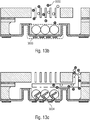
- a so-called preconcentrator is placed in front of the column, as described for example in [5] and in the 13a-c is shown.
- 13a shows a schematic block diagram of a miniaturized gas chromatograph.
- Fig. 13b shows a schematic cross section to illustrate absorption of a gaseous substance 3002.
- 13c shows a schematic cross section of the functional principle of the delivery of the previously adsorbed gaseous substance 3002.
- the gas chromatograph 3000 comprises a volume filled with one or more adsorbents 3006, through which the gas mixture to be examined (gaseous substance 3002) flows for a certain time, around which Enrich substances to be detected. By heating by means of a heating element 3004, these are then suddenly released and introduced into the separation column.
- the introduction of powdered adsorbents in a very small volume is difficult.
- the volume must be filled evenly, on the other hand, trickling through an inlet or outlet must be prevented.
- comparatively large adsorber particles are therefore introduced into the still unclosed cavity of the preconcentrator.
- an adsorbent layer is introduced into the preconcentrator structure by means of ink-jet printing.
- One finding of the present invention is to have recognized that the above object can be achieved by arranging a large number of particles in a recess, the large number of particles having a large total surface area, so that chemical or physical reactions on the surface the particles can run off at a high speed. Combining a part of the particles into a porous structure enables the remaining particles to be prevented from escaping, so that the operation of the reactor is reproducible and permanently enabled.
- a further finding of the present invention is to have recognized that by arranging a heating element adjacent to a multiplicity of particles which are connected to a porous structure by means of a coating, an efficient heating and other areas of the device which have a slight influence on the triggering or accelerating a chemical or physical process is possible, so that the chemical or physical processes can take place at a high process speed.
- a device comprises a substrate which has a cutout and a multiplicity of particles which are arranged in the cutout.
- a first portion of the particles is connected to a porous structure by means of a coating.
- a second proportion of the particles is not connected by means of the coating.
- the first portion of particles is arranged closer to an opening of the recess than the second portion of particles, so that escape of the second portion of particles from the recess through the opening is prevented.
- This enables reaction properties of the uncoated portion of particles to be influenced little or not by the coating.
- a high surface area and thus a high process speed can be obtained by means of the arrangement of particles.
- a medium that should react with the large number of particles or with the aid of them (catalyst) can reach the uncoated particles through the porous structure.
- the first fraction of particles comprises a plurality of cavities which are arranged between the particles of the first fraction and which are at least partially connected to one another, the porous structure being immovably connected to the substrate. It is advantageous in this exemplary embodiment that a medium can flow through the first portion of particles by means of the cavities and thus through the porous structure in order to reach the uncoated particles.
- the opening of the cutout adjoins a cavity of the device.
- the second fraction of particles can be held in place by the first fraction of particles.
- the second portion of particles can be prevented from falling out or trickling.
- the multiplicity of particles comprise a concentrator material which is designed to bind at least one substance from the vicinity of the cutout.
- a device comprises a substrate and a multiplicity of particles which are connected by means of a coating to form a porous structure, the porous structure being immovably connected to the substrate.
- the device further includes a heating element configured to heat the plurality of particles.
- a device comprises a heating element which is spaced apart from the substrate by the plurality of particles, the heating element being arranged on the heating element and being designed to heat the heating element, so that the heating element heats the plurality of particles. It is advantageous in this exemplary embodiment that the heating of the radiator can be given off to a high degree to the particles and only a slight heating of the surrounding substrate takes place. In this way, temperature influence on neighboring structures can be reduced or avoided.
- a device further comprises a sensor element which is arranged adjacent to the plurality of particles and is configured to measure a parameter of the plurality of particles, a parameter of a cavity of the device and / or a parameter of a medium which is between the plurality of particles is arranged to detect. It is advantageous in this exemplary embodiment that process parameters of the process running on or adjacent to the particles can be recorded directly or indirectly, so that control or monitoring of the processes can be precisely controlled.
- a method for producing a device comprises providing a substrate which has a cutout, introducing a large number of particles into the cutout.
- the method further includes coating a portion of the plurality of particles so that the first portion is bonded into a porous structure.
- the coating is carried out by a coating process which has a depth of penetration from an opening of the recess into the recess.
- the penetration depth is set so that a second portion of the particles is not connected by means of the coating and so that the first portion of particles is arranged between the second portion of particles and an environment of the recess and so that the second portion of particles moves to the vicinity of the recess is substantially prevented. This means that the first portion of particles can be arranged facing the opening of the recess.
- a method for producing a device comprises providing a substrate, arranging a multiplicity of particles on the substrate and coating the multiplicity of particles and the substrate.
- the coating is carried out in such a way that the plurality of particles are at least partially coated and connected to form a porous structure, so that the porous structure is immovably connected to the substrate.
- the method further includes arranging a heating element so that heating the heating element heats the plurality of particles.
- the reactors can be, for example, gas chromatographs or preconcentrator elements of gas chromatographs.
- the reactors can also be filters which are designed to filter out substances which are contained in a medium flowing through the filter.
- a reactor may refer to an energy generation device (such as a battery) in which electrical energy is generated based on a surface reaction.
- the exemplary embodiments described below also relate to reactors in the form of getter pumps which are designed to bind a fluid or substances therefrom and thus to reduce a fluid pressure or a substance concentration in a cavity, so that, for example, vacuum-like conditions or at least a reduced (partial -) Pressure prevail in the cavity.
- Fluids that are contacted or contacted with the plurality of particles can be in any, preferably non-solid, state, i.e. are gaseous and / or liquid.
- Fig. 1 shows a schematic side sectional view of a device 10 having a substrate 12.
- the substrate 12 comprises a recess 14, for example a blind hole, a trench or a depression.
- a large number of particles are arranged in the recess 14.
- a first portion 16 of the particles is connected to a porous structure 22 by means of a coating.
- a second portion 18 of the particles is not connected by means of the coating.
- the first portion 16 of the particles is arranged closer to an opening 19 of the recess 14 than the second portion 18 of the particles. Escaping the second portion 18 of particles from the recess through the opening 19 thereof is by means of the porous structure 22, i.e. of the first portion 16 of the particles prevented.
- the porous structure 22 can be firmly connected to the substrate 12, for example in that the first portion 16 and the substrate 12 have the same coating and the coating connects both the particles of the first portion 16 to one another and the porous structure 22 to the substrate 12.
- the porous structure 22 is connected to the substrate 12 in a different manner, for example by a pressure, press or adhesive process.
- the porous structure 22 is designed to allow a first fluid 24 to pass in the direction of the second portion 18. This takes place, for example, in that the porous structure 22 has a multiplicity of cavities which are at least partially connected to one another, so that the fluid 24 can flow through the adjacent cavities.
- the cavities can be obtained in that particles brought into contact with one another have cavities arranged between them, which at least through the coating remain partially unlocked.
- the fluid 24 can reach the second portion 18 of the particles through the porous structure 22.
- the second portion 18 of particles can comprise particles that are designed to react with the fluid 24 and / or to bind the fluid 24 or a substance thereof. If the fluid 24 is only partially bound by the particles or if there is a chemical or physical reaction that changes the fluid 24, a second (possibly modified) fluid 26 can leave the recess 14 through the porous structure 22.
- At least one additional fluid can flow through the porous structure 22 into the recess 14.
- the fluid 24 and the further fluid can react, for example, on the particles, in particular the particles of the second portion 18.
- a surface reaction on the particles of the second portion 18 is thus made possible.
- the coating has appropriate materials, a surface reaction on the particles of the first portion 16 can be made possible.
- the surface on which the surface reaction can take place is increased compared to a planar structure or a column structure based on the large number of particles.
- a reaction property of the particles can be determined or influenced by a material and / or a surface property of the particles.
- a corresponding material or surface property can be influenced or made possible by the coating (in return, however, also suppressed).
- the large number of particles that is to say the particles of the first portion 16 which are connected to form the porous structure 22 and, if appropriate, uncoated particles, can be further modified in further process steps with regard to their reaction properties.
- catalytically active substances can be applied from a solution or a gas phase to the surface of the porous three-dimensional structure 22 in order to enable a catalyst function.
- the first portion 16 can be coated by any suitable method (coating process), for example atomic layer deposition (ALD), physical vapor deposition (PVD) or chemical vapor deposition (Chemical Vapor Deposition - CVD).
- ALD atomic layer deposition
- PVD physical vapor deposition
- CVD chemical vapor deposition
- the first portion 16 can be coated by appropriately selecting the coating parameters or terminating or interrupting the coating if a sufficient number of particles are coated so that the first portion 16 can form the porous structure 22.
- the coating process can have a penetration depth 21 which describes an effectiveness (coating of particles) of the coating process starting from the opening 19 along a depth direction 23 into the recess 14.
- particles of the first portion 16 are arranged essentially at a distance from the opening 19 which is less than or equal to the penetration depth 21 of the coating process.
- the particles of the second portion 18 can be arranged at a distance from the opening 19 that is greater than the penetration depth 21 of the coating process.
- the setting of the penetration depth 21 can include setting a parameter of the coating process, such as pressure, time, temperature or the like.
- the penetration depth 21 can be set such that a dwell time of a first or second reactant is set for an atomic layer deposition (coating process) such that the reactant only removes the particles from the opening 19 or a top surface (fill level) of the particles up to the penetration depth 21 penetrates.
- a coating is carried out, for example, in that both reactants come into contact with the particle (sequentially one after the other) and are deposited on the particle, for example.
- a reactant can be introduced and portions not arranged on particles can be removed (suctioned off) again before another reactant is introduced. If both reactants come into contact with each other on the particles, a coating can be formed there. If the residence time is set so that at least one of the reactants does not exceed the penetration depth 21, a coating of particles which are at a greater distance from the opening 19 than the penetration depth 21 can be reduced or avoided. Alternatively, for example, a coating duration of a CVD deposition can be set such that a coating of particles with a greater distance from the opening 19 than the penetration depth 21 is substantially or completely prevented. E.g. When using Al 2 O 3, a "penetration depth" within which the particles are coated can be set within wide limits. Aspect ratios over 1000 can be achieved.
- the coating can be carried out from one side of the surroundings of the recess 14 in a direction of a volume of the recess. This enables particles (the first portion 16) arranged adjacent to the opening 19 of the recess to be coated, while particles spaced apart from the opening 19 remain uncoated.
- a number of particles of the second portion can be a factor of at least 1, 2, 10 or greater compared to a number of particles of the first portion. This means that more uncoated particles than coated particles can be arranged.
- the porous structure 22 forms a porous membrane.
- the porous structure 22 enables the second portion 18 of the particles to interact with the fluid 24 (medium).
- the material of the substrate 12 can substantially prevent contact of the fluid 24 with the second portion 18 of the particles, that is to say that a size of the opening 19 of the recess 14 can influence the entry and / or exit of media towards the uncoated particles or determine.
- the substrate 12 can be a semiconductor material, for example.
- the semiconductor material can be, for example, a silicon material or a gallium arsenide material.
- the substrate 12 can comprise a glass material, a ceramic material, a glass ceramic material and / or a plastic material.
- the substrate 12 can have a doping.
- the semiconductor material can be doped, for example with a boron material.
- the substrate 12 is a MEMS wafer.
- the substrate 12 can have a planar or non-planar shape (for example curved).
- Fig. 2 shows a schematic side sectional view of a device 20, in which the first portion 16 of the particles arranged in the recess 14 comprises all or almost all of the arranged particles.
- the device 20 comprises a heating element 28, which is designed to heat the plurality of arranged particles.
- the heating element 28 can be enclosed by the particles. That enables a high proportion of one Surface of the heating element 28 can be contacted with the particles and a high level of thermal energy is emitted to the particles 16 when the heating element 28 is activated.
- the heating element 28 can be arranged at a distance from the substrate 12. This enables direct release of thermal energy from the heating element 28 to the substrate 12 to be reduced or prevented. This enables a slight heating of the substrate 12 based on an activation of the heating element 28, so that a thermal influence on the substrate 12 and neighboring structures is also slight.
- a device can have a plurality of cutouts (preconcentrators), in each of which particles are arranged. Any number of particles in a respective recess can be used as a preconcentrator for a specific substance or a specific concentration of a substance and can be heated independently of one another with a heating element in order to release the enriched substance in each case. A reduced or slight mutual thermal influence of the preconcentrator with one another enables precise operation of the device (s).
- the device 20 is described in such a way that only the first portion 16 of particles is arranged, the second portion of particles can also be arranged according to alternative exemplary embodiments, as is in connection with FIG Fig. 1 is described.
- a conductive element 32 can be arranged on one side of the substrate 12, wherein the conductive element 32 is designed to heat up when activated.
- the conductive element 32 can be designed to heat up when an electrical current flows through it.
- the conductive element 32 can be, for example, a structured metal, such as copper, aluminum, gold or the like.
- the conductive element 32 can also be a doped or undoped semiconductor material.
- the semiconductor material can be silicon or gallium arsenide (GaAs), for example. Doping can take place, for example, using boron.
- Both the substrate and the electrically conductive element 32 can alternatively or additionally (alternating in time or simultaneously) be used for temperature measurement.
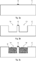
- the electrically conductive element can have a material with a suitable temperature coefficient. Metals such as gold or platinum are particularly suitable for this. In other words shows Fig. 3a deposition and structuring of one or more metals on a silicon substrate, which serve for the electrical connection of the heater and / or as a temperature sensor.
- Fig. 3b schematically shows a subsequent arrangement of two recesses 14a and 14b in the substrate 12.
- FIG Fig. 3b the arrangement of two recesses 14a and 14b is shown, only one recess or alternatively more than two recesses can be arranged.
- Fig. 3b etching one or more cavities in the substrate, which specifies a shape and / or dimensions of the heating elements and the three-dimensional body.
- a first plurality of particles 34 is arranged in the cavity 14a and a second plurality of particles 34 in the cavity 14b.
- the substrate 12 has a further recess 14b, in which a further large number of particles is arranged.
- the particles arranged in the cutouts 14a and 14b can have the same or different materials and / or the same or different shapes or sizes. In other words shows Fig. 3c introducing the particles from which the three-dimensional body should consist into the cavities. At this point, the particles can still be loosely arranged on or on top of one another.
- a device 30 comprises the particles, which each form a porous structure 22a or 22b arranged in the recess 14a or 14b.
- the electrically conductive element 32 is arranged on a part of the substrate 12 which spaces the two recesses 14a and 14b from one another.
- the porous structures 22a and 22b can each be connected to the substrate 12.
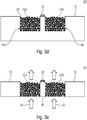
- Fig. 3d solidification of the particles by coating for example with Al 2 O 3 using ALD. This layer can be removed from the areas of the metal structures (conductive element 32) which serve for the electrical contacting of heaters and temperature sensors.
- the substrate 12 can be partially removed, so that the porous structures 22a and 22b on two sides thereof are non-contact with the substrate 12.
- the device 30 is modified to a device 30 '.
- the removed substrate can be, for example, a rear side of a wafer in which the device is formed.
- the term "back” is not intended to have any restrictive effect here. It goes without saying that, depending on the orientation of the device in space, terms such as “top”, “bottom”, “left” or “right” and the respective sides can be interchanged as desired.
- a second opening is created in each of the recess 14a and the recess 14b, so that the fluid 24 can flow through the porous structures 22a and 22b.
- the partial removal of the substrate 12 can, for example, result in a part 36 of the substrate 12 being exposed with respect to the remaining substrate 12.
- the remaining part 36 can be referred to as a heating element if the electrically conductive element 32 is designed to emit thermal energy based on an electrical current that flows through the electrically conductive element 32.
- the removal of the substrate 12 further enables electrical insulation of the radiator 36 and thus of the conductive element 32 from the substrate 12.
- Activation of the conductive element 32 can lead to heating of the radiator 36, which is designed to remove thermal energy from the electrically conductive Pick up element 32 and deliver it to the porous structures 22a and 22b.
- the heating element 36 and the electrically conductive element 32 are thus spaced apart from the remaining substrate 12 by means of the porous structures 22a and 22b.
- the heating element 32 is arranged with respect to the particles, which means that it is designed to heat the plurality of particles (porous structures 22a and 22b) by means of the heating element 36.
- a heating of the particles is greater than a heating of the substrate.
- the heating element can also be arranged with respect to the plurality of particles in such a way that it has direct contact with the particles and heats the particles directly.
- the porous structures 22a and 22b are a one-piece element, for example if the heating element 36 is an island structure which is enclosed by the particles of the porous structure.
- the heating element 36 is an island structure which is enclosed by the particles of the porous structure.
- Fig. 3e removing the silicon from the back of the substrate, for example by grinding and / or polishing, until the porous three-dimensional structure (porous structure) is exposed, so that a fluid moves the three-dimensional structure from one side to the other (e.g. from top to bottom or vice versa).
- they show 3a-e a production of a porous three-dimensional (3D) structure with embedded heaters or temperature sensors on a silicon substrate.
- the heating element 36 can consist of the substrate material itself and is specified, for example, in its lateral dimensions when the cavity is etched for the particles to be introduced.
- 12 connection pads and / or conductor tracks made of conductive material are arranged on the substrate. The arrangement can take place before the etching or after the etching.
- the silicon can be removed from the back as in Fig. 3e is shown. On the one hand, this enables the fluid 24 to flow through the porous 3D structure along one direction (for example perpendicularly).
- the heating element embedded in the 3D structure is thermally and electrically separated from the substrate 12.
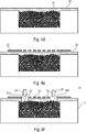
- the 4a-f schematically show a method for producing a device 40 Fig. 4a is shown, the recess 14 is formed in the substrate 12, for example by means of an etching process. Then it follows as in Fig. 4b is shown, an arrangement of possibly loose particles 34 in the recess 14. As shown in Fig. 4c the porous structure 22 is obtained by coating the particles.
- a material layer 38 is arranged at the opening of the recess on the porous structure 22, which extends flatly over the porous structure 22.
- a side of the material layer 38 facing away from the porous structure 22 has a reduced unevenness compared to the porous structure 22.
- the side of the material layer 38 facing away from the porous structure 22 is flat.
- the material layer 38 can be arranged by means of suitable molding or deposition processes.
- the arranged material layer 38 can be processed with a subsequent processing, such as a grinding process or a polishing process, so that it has a low surface roughness.
- Material layer 38 may include electrically insulating materials, such as a resin or an undoped semiconductor material. Alternatively or additionally, the material layer 38 can comprise a plastic. This enables a passivating property of the material layer 38 to be obtained.
- one or more electrically conductive elements 32 can be arranged on the material layer 38.
- Fig. 4e shows Fig. 4e a separation and structuring one or more metals on the planarized 3D structure, wherein the metal or metals can be used as a heating element and / or as a temperature sensor.
- fluidic connections 44a and 44b are produced, for example by partially removing the material layer 38 and possibly the electrically conductive element (s) 22 so that the fluid 24 towards the porous structure 22 and / or the fluid 26 away from the porous structure Structure 22 can flow. Remaining areas of the material layer 38 can be used as a radiator.
- the arrangement of the electrically conductive element 32 on the material layer enables further degrees of freedom during the manufacture of the device 40.
- any structure of the electrically conductive element (s) 32 can be produced.
- the arrangement of the material layer 38 enables a flat arrangement of the electrically conductive element (s) 32 with respect to the porous structure 22.
- the heating element is formed by planar metal structures (electrically conductive element 32), which is applied to the porous 3D structure 22 after the passivation layer has been deposited and its optional planarization.
- planar metal structures electrically conductive element 32
- a thermal coupling to the porous 3D structure 22 can be reduced, but insulation from the carrier substrate 12 is still provided without the carrier substrate having to be removed on the back.
- thermal conductivity of the porous structure 22 may be lower compared to thermal conductivity of a material from which the particles are made.
- a large-area arrangement of radiators for example through the radiator 36 or the material layer 38 between the fluidic connections 44a and 44b, enables a high transfer of thermal energy to the porous structure 22 (heating the same) or to the electrically conductive element 32 (sensing the temperature) the porous structure 22).
- the material layer 38 and / or the electrically conductive element 32 can also be arranged along lateral regions of the substrate 12 which are arranged outside the recess 14. This makes it possible, for example, to heat the surrounding substrate 12 or to sense a temperature of the surrounding areas, for example if thermal insulation of the substrate 12 from adjacent areas is not required.
- an arrangement of a heating element or radiator or a temperature sensor is advantageous since process parameters can be influenced precisely and / or can be tracked with a high degree of precision, so that precise process control is made possible.
- FIG. 12 shows a schematic side sectional view of a device 50, compared with the device 40 Fig. 4f the fluidic connections 44a and 44b are passed through the substrate 12.
- the material layer 38 can be arranged in a large area so that it covers the porous structure 22 to an increased extent. This enables the electrically conductive element (s) 32 to be arranged on a larger area.
- further fluidic connections can be arranged, wherein the further fluidic connections can also be passed through the material layer 38.
- the fluidic connections 44a and / or 44b can be produced, for example, by dry etching.
- a paint mask can be arranged on the substrate 12, which influences a dimension of the fluidic connections 44a and 44b.
- the surface of the porous MEMS structures described above can be produced both after completion and during the manufacturing process can be specifically functionalized for different applications.
- additional layers can be deposited using ALD or comparable processes, such as MLD.
- ALD allows the deposition of many metal oxides, but also nitrides and noble metals such as ruthenium or platinum.
- MLD enables the deposition of hybrid organic-inorganic layers.
- the wetting behavior of the surface can be adjusted by an appropriate, preferably wet chemical treatment.
- a MEMS structure, as for example in Fig. 5 can be used, for example, as a chromatographic column after the surface of the porous structure 22 has been rendered hydrophobic.
- the MEMS structure 50 can also be used as a chromatographic column if it is carried out without the electrically conductive elements 32.
- the particles can be heated externally to release the substances bound to the particles.
- first portion 16 of particles is covered by a thermally conductive layer (material layer 38).
- One or more heating elements are connected to the first portion 16 by means of the material layer 38.
- the heating element or elements are designed to heat the material layer 38, the thermal energy being at least partially passed on to the first portion 16 of the particles in order to heat them.
- a heating of the particles achieved in this way can be greater than a heating of the substrate 12, which means that a thermally reduced coupling or even decoupling of the substrate 12 shown can be obtained from further regions of the substrate.
- the plurality of particles may comprise one or more concentrator materials before or after the coating, which is designed to bind at least one substance from the vicinity of the recess.
- the uncoated particles or at least parts thereof can consist of the concentrator material.
- the coating can also comprise the concentrator material.
- the bound substance can be released from the environment based on the heating.
- the device 50 can be used as a chromatographic column and, for example, can be arranged adjacent to a device 10, 20, 30 or 30 'operated as a preconcentrator. Materials released by the preconcentrator (bound substances) can be through the fluidic connections to the particles of the device chromatographic column (such as device 50) and analyzed.
- the preconcentrator and the chromatographic column can, for example, be arranged on or on a common substrate or chip.
- the device 50 can be used as a chromatographic column and a preconcentrator can be connected.
- a plurality (i.e., two or more) preconcentrators can be combined with a chromatographic column, wherein at least one preconcentrator can comprise particles and / or a concentrator materials for concentrating at least two substances. At least one preconcentrator can comprise a further recess with further particles, so that a first substance can be concentrated in a first recess and a second substance can be concentrated in a second recess.
- a chromatograph can enable different substances to be separated in a mixture, the substances being adsorbed to different extents by the at least one concentrator material and, accordingly, passing through the column of the chromatograph at different speeds.
- the at least one concentrator material can be designed to adsorb one or more substances as completely as possible and then release them suddenly in order to feed them to the chromatographic column, in which the separation then takes place.
- the concentrator can increase the concentration of the substances to be detected in the gas that passes through the column. This is advantageous in the case of a low separation performance, for example of micromechanical columns. Another advantage is, for example, the general increase in the detection limit (i.e. the minimum concentration that can be detected in a gas).
- Fig. 6 shows a schematic side sectional view of a device 60, as can be obtained, for example, when in connection with FIG Fig. 3d Coating described is carried out such that a sufficient number of particles is coated by the coating of the particles down to the penetration depth 21 and the porous structure 22a and / or 22b a sufficient extension along a depth direction 46 from the opening of the recess 14a or 14b to an opposite side of the substrate 12.
- the expansion of the porous structures 22a and 22b increases with increasing depth of penetration (possibly residence time of reactants and / or coating duration) and along the depth direction 46.
- the porous structures 22a and 22b can, as is related to Fig. 1 is described as rigid porous membranes.
- the particles of the second portions 18a and 18b can be as loose, uncoated particles are present, so that the surface property or material property of the particles of the second portions 18a or 18b is decisive for the respective reaction of the device 60 or at least makes a contribution.
- Fig. 7 shows a schematic side sectional view of a device 70, as it can be obtained, for example, when the coating, as in connection with the Fig. 4c has been described in such a way that the porous structure 22 has a sufficient extent along the depth direction 46 due to the coating of the particles down to the penetration depth 21.
- the material layer 38 and electrically conductive elements 32a-e can also be compared to the device 40 Fig. 4f , have further openings so that a plurality of fluidic openings are created or a large-area penetration of the porous structure 22 by the fluid is made possible.
- the electrically conductive elements 32a-e can each be arranged on a section of the material layer 38 and form a heating element 48a-e with these.
- the introduced particles are largely or completely coated, that is to say possibly down to the bottom of the cavity (recess) or connected to one another. If the coating process (in particular the residence time of the reactants) is modified, it can be achieved that the introduced particles are only coated to a certain depth.
- Falling out of the non-coated, ie loose particles can be prevented by connecting the porous structure to the substrate 22 or preventing the porous structure 22 from detaching from the substrate. It can thereby be achieved that materials in powder form, ie the second portion of the particles, are enclosed in a miniaturized container, ie the recess, in such a way that the uncoated particles can interact with the surrounding medium through the solidified area.
- the manufacturing process partially corresponds to processes as they are related to the 3a-e and 4a-f have been described, but with the difference that the particles introduced are only coated on the surface in the corresponding steps. In order to avoid premature interaction of the reactive particles with the environment, ALD processes can also be used low temperatures have a high effectiveness, as is the case for example for Al 2 O 3 .
- the Fig. 6 and 7 show them to the Fig. 3d or 4f analog, at least partially completed MEMS structures.
- the contact between the uncoated particles and an environment of the recess is only possible through the porous membrane.
- Removing the carrier substrate as related Fig. 3e has been described, for example.
- the embedded heaters 48a-e can therefore remain connected to the carrier substrate.
- Thermal decoupling between the heating elements 48a-e and other areas of the substrate 12 can, as described above, be achieved by additional process steps.
- the devices 60 and / or 70 can furthermore have fluidic connections through the substrate 12 to the particles of the second portion 18 or 18a and / or 18b.
- the second portion 18 or 18a and / or 18b can be partially coated through a fluidic connection in order to obtain a further porous structure in the region of the fluidic connection and thus allow the second portion of particles to escape through the fluidic connection prevent.
- the particles can be, for example, an adsorbent in powder form, for example Carbopack, or other particles.
- Carbopack a MEMS structure can be used, for example, as a preconcentrator for a miniaturized gas chromatograph.
- An adsorber array can be realized by sequentially filling adjacent cavities with different adsorbents. Thermal insulation of adjacent cavities and / or independent heating of the particles within the respective cavity, independently of one another, enables largely independent heating of the individual array elements, which enables complex fluid mixtures to be analyzed.
- a chemical reaction with the substances (particles) enclosed in the respective micro-container can also be triggered.
- a corresponding chemical reaction can be obtained by targeted contact with moisture or liquids or gases.
- electrical energy can be obtained based on a chemical reaction, for example if a device described above is used as a battery, for example a zinc air battery, which is activated by supplying an alkaline electrolyte.
- the large number of particles can be designed to bind at least one substance and to chemically or physically react the substance with a medium that is contacted or contacted with the plurality of particles.
- FIG. 6 and 7 Another application of the in the Fig. 6 and 7
- the structures shown are in the area of miniaturized getter pumps. Titanium (Ti) and zirconium (Zr) -based getters are known, which are used in the form of applied layers.
- Ti Titanium
- Zr zirconium
- an effective surface of the getter materials can be increased compared to a flat arrangement, which leads to a small space requirement for the getter material and / or to a reduced space or surface requirement of the getter on the substrate.
- Fig. 8 shows a schematic side sectional view of a device 80, in which the second portion 18 of particles can be used as a getter pump.
- the device 18 comprises the substrate 12, into which the recess 14 is made.
- the substrate 12 is, for example, a MEMS wafer.
- the device 80 further comprises a MEMS structure 52, which is arranged on the substrate 12 and provides a MEMS function.
- the MEMS structure can be a seismic mass, so that the device 80 can be used as an inertial sensor.
- the MEMS structure can also be an actuator or sensor.
- a cap structure 54 is arranged on the substrate 12.
- the cap structure 54 can be connected to the substrate 12 by means of a seal 56.
- the seal 56 can be an adhesive (adhesive) or the like, with which the cap structure 54 and the substrate 12 are glued.
- the cap structure 54 and the substrate 12 can also be bonded to one another.
- the substrate 12, the cap structure 54 and the seal 56 enclose the MEMS structure 52, so that an inner volume (cavity) 58 of the device 80 is formed, in which the MEMS structure 52 is arranged.
- the opening of the recess 14 adjoins the cavity 58 of the device 80.
- At least the second portion 18 of the particles is designed to bind a fluid (for example air) located in the cavity 58 in order to generate a vacuum or at least a negative pressure in the cavity 58.
- the second portion 18 of particles may be formed to extract a particular substance from the cavity, for example to reduce corrosion or other interactions between the substance and the MEMS structure 52.
- the cap structure 54 can be formed, for example, from the same material as the substrate 12. In simple terms, the cap structure 54 can be a further substrate.
- the cavity can thus be sealed off from the surroundings of the device 80.
- the plurality of particles can be designed to bind gas molecules arranged in the cavity after the sealing, so that a gas pressure inside the cavity is reduced in relation to a gas pressure outside the device 80.
- Fig. 9a shows a schematic side sectional view of a device 90 which is modified with respect to the device 80 in such a way that the cap structure is formed by a substrate 12b which has the cutout 14.
- the cap structure is a substrate and has the getter pump.
- a mechanically firm connection of the porous structure 22 to the substrate 12b makes it possible to prevent the second portion 18 from trickling out of the cavity 14.
- the device 90 can be positioned in space such that the gravitational force moves the particles of the second portion 18 in the direction of the cavity 58 draws.
- the porous structure 22 can for example be mechanically firmly connected to the substrate 12b by means of the coating.
- the porous structure 22 can also be pressed (pressed) into the opening of the recess 14, for example, so that resulting mechanical forces prevent the porous structure 22 from falling out of the recess 14.
- Fig. 9b shows a schematic side sectional view of a device 90 ′, which is opposite the device 90 Fig. 9a is modified such that the recess 14 has a variable dimension along a lateral direction 62 perpendicular to the depth direction 46.
- the recess 14 is configured such that it tapers in the direction of the cavity 58.
- the porous structure 22 may have a dimension along the lateral direction 62 that is greater than or equal to the dimension of the opening of the recess 14 along the lateral direction 62.
- the porous structure 22 Based on the tapering of the recess 14, it is possible to prevent the porous structure 22 from falling out or passing through the opening of the recess 14. It is thus possible to dispense with fastening the porous structure 22 to the substrate 12b by means of the coating. Movement of the porous structure 22 may be in a direction parallel to the depth direction 46 through the second Portion 18 of the particles and in an opposite direction can be prevented or at least restricted by the tapering of the recess 14. With the same volume of the recess 14, a dimension of the opening of the recess can be reduced. Compared to the device 90, the getter pump, ie the second portion 18, can be arranged in a larger volume, even if a number of coated particles, ie the first portion 16, is the same or reduced. This enables a high capacity of the getter pump, ie a high degree of fluid or substance can be sucked out (bound) from the cavity 58.
- Fig. 8 , 9a and 9b an easy way of integrating a particle-based getter pump into a MEMS system.
- the getter pump ie the getter function
- the getter pump can be activated by external heating of the particles.
- the device 80, 90 or 90 has a heating element and / or a heating element in order to be activated independently of external temperatures.
- Getter activation can be carried out by tempering after wafer bonding.
- a getter pump with an integrated heater that is thermally insulated from the substrate, as described for previous exemplary embodiments, can allow repeated getter activation at the chip level without the entire MEMS system being heated. Thanks to the large area and the large volume of the particles enclosed in the cavity, a significantly higher absorption capacity is possible compared to planar structures, in particular getter thin layers.
- heating elements and / or a heating element have been described in previous exemplary embodiments such that they are arranged adjacent to or on the porous structure, it is also conceivable that a heating element and / or a heating element is surrounded by uncoated particles.
- one or more further sensors can be arranged with respect to the recess 14 and / or the cavity 58.
- the sensors can be designed to measure a parameter of the plurality of particles (for example a temperature, a pressure or a movement), a parameter for the cavity (for example a temperature, a fill level that the fluid has in the cavity), a type of medium, with which the cavity 14 is at least partially filled, or the like.
- a sensor can be designed to detect a parameter of the medium, ie of the fluid, which is arranged between the plurality of particles. This can be, for example a flow rate, a pressure, a temperature or a nature (somewhat basic or acidic) of the fluid.
- a device can furthermore have an electrode structure which is in contact with the first portion and / or the second portion of particles and is designed to apply or detect an electrical potential between electrodes of the electrode structure, which means an electrical potential on or between the particles can be generated or recorded.
- Exemplary embodiments described above are independent of a size (for example diameter or lateral dimension).
- the particles are designed, for example, as aluminum oxide particles (fragments), they can have a diameter of, for example, between 1 and 20 ⁇ m, 2 and 15 or between 5 and 12 ⁇ m.
- these can have a diameter or a lateral dimension in a range from 0.1 ⁇ m to 20 ⁇ m, 0.5 ⁇ m to 5 ⁇ m or 0.8 ⁇ m to 1.2 ⁇ m.
- the coating can also be used that the porous structure 22 is sealed, ie the voids between the particles are closed.
- a recess can also be closed by means of the coating.
- the substrate can also have other shapes.
- the substrate can have a curved shape (for example a dome structure) or a sectionally planar and / or kinked shape.
- aspects have been described in connection with a device, it goes without saying that these aspects also represent a description of the corresponding method, so that a block or a component of a device can also be understood as a corresponding method step or as a feature of a method step. Analogously, aspects that have been described in connection with or as a method step also represent a description of a corresponding block or details or feature of a corresponding device.
- a device can have the following features: a substrate 12 which has a recess 14; 14a, 14b; and a plurality of particles 34 that are in the recess 14; 14a, 14b are arranged; wherein a first portion 16 of the particles 34 by means of a coating to form a porous structure 22; 22a, 22b and a second portion 18 of the particles 34 is not connected by means of the coating; and wherein the first portion 16 of particles 34 closer to an opening of the recess 14; 14a, 14b is arranged as the second portion 18 of particles 34, so that the second portion 18 of particles 34 escapes from the recess 14; 14a, 14b is prevented by the opening.
- the first portion of the particles 34 may comprise a plurality of cavities arranged between the particles 34 of the first portion of the particles 34, the cavities being at least partially connected to one another and the porous Structure 22; 22a, 22b is immovably connected to the substrate 12.
- the second portion 18 can have a number of particles 34 which is greater than a number of particles 34 of the first portion 16 by a factor of at least 1.1 .
- the coated first portion 16 of the particles 34 can form a porous membrane and an interaction of the second portion 18 of the particles 34 with a medium that is in an environment outside the the recess 14; 14a, 14b is arranged, made possible by the porous membrane and essentially prevented by other areas.
- the substrate 12 can have a further recess 14b in which a further multiplicity of particles 34 are arranged; a first portion 16 of the further particles 34 by means of a further coating which is related to the first Portion of the further particles 34 is arranged, can be connected to a further porous structure 22b and a second portion 16 of the further particles 34 cannot be connected by means of the further coating; and wherein the first portion 16 of the further particles 34 can be arranged and configured between the second portion 18 of the further particles 34 and an environment of the further recess 14b, in order to move the second portion 18 of the further particles 34 towards the environment of the further recess 14b essentially prevent.
- the opening of the recess 14; 14a, 14b adjoin a cavity 58 of the device.
- the cavity can be formed in the device by the substrate 12 and a further substrate 12b arranged on the substrate 12.
- the device can further comprise a heating element 28; 32; 32a-f disposed with respect to the plurality of particles 34 and configured to heat the plurality of particles 34.
- the first portion of particles 34 can be covered by a thermally conductive layer 38, the heating element 28; 32; 32a-f is connected to the first portion 16 by means of the thermally conductive layer 38, the heating element 28; 32; 32a-f is configured to heat the thermal conductive layer 38, which is configured to heat the first portion 16 of the particles 34, and wherein a heating of the particles 34 is greater than a heating of the substrate 12.
- the plurality of particles 34 in the device can have a concentrator material that is designed to remove at least one substance from the vicinity of the recess 14; 14a, 14b to bind.
- the device can comprise a heating element 28; 32; 32a-f, which is configured to heat the particles 34, the particles 34 being configured to release the bound substance from the environment based on the heating.
- a device can have the following features: a substrate 12; a plurality of particles 34 which are formed into a porous structure 22; 22a, 22b is connected, wherein the porous structure 22; 22a, 22b is immovably connected to the substrate 12; and a heating element 28; 32; 32a-f configured to heat the plurality of particles 34.
- the device may comprise a heating element 36 which is spaced apart from the substrate 12 by the plurality of particles 34, the heating element 28; 32; 32a-f is arranged on the heating element 36 and is designed to heat the heating element 36, so that the heating element 36 heats the plurality of particles 34.
- the porous structure 22; 22a, 22b are at least partially covered by a thermally conductive layer 38, the heating element 28; 32; 32a-f is arranged on the thermally conductive layer 38, and is designed to heat the plurality of particles 34 by heating the thermally conductive layer 38.
- a first portion 16 of the particles 34 can be formed into the porous structure 22; 22a, 22b and a second portion 18 of the particles 34 are not connected by means of the coating; the first portion of particles 34 closer to an opening of a recess 14; 14a, 14b of the substrate 12 is arranged as the second portion 18 of particles 34, so that the second portion 18 of particles 34 escapes from the recess 14; 14a, 14b is prevented by the opening.
- the device can be a micromechanical structure.
- the porous structure 22; 22a, 22b for a fluid 24, 26 to be permeable According to a seventeenth aspect with reference to at least one of the first to sixteenth aspects, the porous structure 22; 22a, 22b for a fluid 24, 26 to be permeable.
- the device may further include a sensor element 32, which is arranged adjacent to the plurality of particles 34 and is configured to one To record parameters of the plurality of particles 34, a parameter of a cavity 58 of the device and / or a parameter of a medium which is arranged between the plurality of particles 34.
- the device may further comprise at least one electrode structure that is in contact with the plurality of particles 34 and that is configured to increase an electrical potential of the particles 34 in contact with the electrode structure detect or apply the electrical potential to the particles 34 contacted with the electrode structure.
- the plurality of particles 34 can be configured in the device to bind at least one substance and the substance with a medium that is brought into contact with the plurality of particles 34, to react chemically or physically.
- the plurality of particles 34 can be formed in the device in order to bind gas molecules, the recess 14; 14a, 14b is connected via the opening to a cavity 58 of the device, the cavity 58 being opposite an environment of the device 80; 90; 90 ′ is sealed, and wherein the plurality of particles 34 is designed to bind gas molecules remaining in the cavity 58, so that a gas pressure inside the cavity 58 is reduced with respect to a gas pressure outside the cavity 58.
- a material of the substrate may comprise one of a semiconductor material, a glass material, a ceramic material, a glass ceramic material and a plastic material.
- a reaction property of the particles of the first or second portion 16, 18 in the device can be influenced by a material or a surface property of the particles.
- a material or surface property can be in the device the particles of the first portion 16 may be influenced, enabled or suppressed by the coating.
- a catalytically active substance can be arranged in the device on a surface of the porous structure 22, the porous structure 22 being designed to perform a catalytic function.
- a further layer can be arranged on the porous structure 22 in the device, the further layer providing a functionalization of the porous structure 22.
- a method for producing a device can have the following steps: providing a substrate 12 which has a recess 14; 14a, 14b; Introducing a plurality of particles 34 into the recess 14; 14a, 14b; Coating a first portion 16 of the plurality of particles so that the first portion 16 forms a porous structure 22; 22a, 22b is connected using a coating process which has a penetration depth 21 from an opening 19 of the recess 14 along a depth direction 23 into the recess 14; and wherein the depth of penetration 21 of the coating process into the recess 14 is set such that a second portion 18 of the particles 34 is not connected by means of the coating, and so that the first portion 16 of particles 34 is between the second portion of particles 34 and an environment the recess 14; 14a, 14b is arranged and a movement of the second portion 18 of particles 34 towards the surroundings of the recess 14; 14a, 14b is substantially prevented.
- coating from one side of the surroundings of the recess 14; 14a, 14b in the direction of a volume of the recess 14; 14a, 14b are carried out so that particles 34 of the first portion 16 arranged adjacent to the opening are reached and coated based on the depth of penetration of the coating process by the coating process and particles of the second portion 18 spaced apart from the opening are not coated.
- a method for producing a device can have the following steps: providing a substrate 12; Disposing a plurality of particles 34 on the substrate 12; Coating the plurality of particles 34 and the substrate 12 so that the plurality of particles 34 are at least partially coated and to form a porous structure 22; 22a, 22b and so that the porous structure 22; 22a, 22b is immovably connected to the substrate 12; and disposing a heating element so that heating the heating element heats the plurality of particles 34.
- the coating step may be carried out by chemical vapor deposition, atomic layer deposition or atomic vapor phase deposition.
Abstract
Eine Vorrichtung umfasst ein Substrat, das eine Aussparung aufweist und eine Vielzahl von Partikeln, die in der Aussparung angeordnet sind. Ein erster Anteil der Partikel ist mittels einer Beschichtung zu einer porösen Struktur verbunden. Ein zweiter Anteil der Partikel ist nicht mittels der Beschichtung verbunden. Der erste Anteil von Partikeln ist näher an einer Öffnung der Aussparung angeordnet als der zweite Anteil von Partikeln, so dass ein Entweichen des zweiten Anteils von Partikeln aus der Aussparung durch die Öffnung verhindert wird.A device includes a substrate that has a recess and a plurality of particles that are arranged in the recess. A first portion of the particles is connected to a porous structure by means of a coating. A second proportion of the particles is not connected by means of the coating. The first portion of particles is arranged closer to an opening of the recess than the second portion of particles, so that escape of the second portion of particles from the recess through the opening is prevented.
Description
Die vorliegende Erfindung bezieht sich auf eine Vorrichtung mit einer Vielzahl von Partikeln und auf ein Verfahren zum Herstellen derselben. Die vorliegende Erfindung bezieht sich ferner auf miniaturisierte Reaktoren mit großer innerer Oberfläche für chemische oder physikalische Prozesse.The present invention relates to an apparatus having a plurality of particles and a method for producing the same. The present invention further relates to miniaturized reactors with a large inner surface for chemical or physical processes.
Mikroreaktoren, d.h. Volumina im µl-Bereich zur Durchführung chemischer Reaktionen oder physikalischer Prozesse in miniaturisierten Systemen, sind von erheblichem Interesse für viele Anwendungen. Dazu gehören Durchflusszellen zur Synthese oder Detektion chemischer Verbindungen, zur Filterung oder Vermischung von Gasen oder Flüssigkeiten, zur selektiven Absorption von Substanzen aus Gasen oder Flüssigkeiten, aber auch z.B. Brennstoffzellen zur Energiegewinnung oder Container mit reaktiven Substanzen, die gezielt aktiviert werden können. In vielen Fällen ist dabei erforderlich, in einem miniaturisierten Hohlraum mit definierten Abmessungen und vorgegebenen Zu- bzw. Austrittsöffnungen eine möglichst große innere Oberfläche bereitzustellen.Microreactors, i.e. Volumes in the µl range for carrying out chemical reactions or physical processes in miniaturized systems are of considerable interest for many applications. These include flow cells for the synthesis or detection of chemical compounds, for filtering or mixing gases or liquids, for the selective absorption of substances from gases or liquids, but also e.g. Fuel cells for energy generation or containers with reactive substances that can be specifically activated. In many cases, it is necessary to provide the largest possible inner surface in a miniaturized cavity with defined dimensions and predetermined inlet and outlet openings.
Die Herstellung poröser Keramiken oder Metalle an sich ist industriell etabliert. Es sind viele Verfahren bekannt, vom Sintern von Pulvern bis zur Pyrolyse von Keramik-Polymer-Schäumen. Allen Verfahren ist gemeinsam, dass Temperaturen von zumeist deutlich über 400°C benötigt werden. Ferner entstehen Rohlinge des porösen Materials, die durch weitere Bearbeitungsschritte zuerst in die für eine bestimmte Anwendung erforderliche Form gebracht und dann in den benötigten Hohlraum integriert werden müssen. Beides ist nicht kompatibel zu miniaturisierten Systemen.The production of porous ceramics or metals per se is established industrially. Many processes are known, from the sintering of powders to the pyrolysis of ceramic polymer foams. All processes have in common that temperatures of mostly well over 400 ° C are required. In addition, blanks of the porous material are formed, which first have to be brought into the shape required for a specific application by further processing steps and then have to be integrated into the required cavity. Both are not compatible with miniaturized systems.
Große Oberflächen für MEMS-Anwendungen (MEMS = Microelectromechanical System, mikroelektromechanisches System) können durch Strukturieren von Silizium mittels Trockenätzen oder dessen anodische Oxidation erzeugt werden.
Größere Oberflächen lassen sich durch elektrochemisches Ätzen (anodische Oxidation) von Silizium in HF-basierten Lösungen (HF = Fluor (F) - Wasserstoff (H)) erzielen. In [2] wird auf diese Weise eine 30 µm dicke Silizium mit vertikalen Poren hergestellt und vom Substrat abgelöst. Anschließend wird die Membran durch Kleben in ein mikrofluidisches System aus Kunststoff integriert.Larger surfaces can be achieved by electrochemical etching (anodic oxidation) of silicon in HF-based solutions (HF = fluorine (F) - hydrogen (H)). In [2] a 30 µm thick silicon with vertical pores is produced in this way and detached from the substrate. Then the membrane is integrated into a microfluidic system made of plastic.
Auf ähnliche Weise können poröse Alumina-Schichten (Alumina = Aluminiumoxid) durch anodische Oxidation von Aluminium erzeugt werden. In [3] wird ein Katalysator beschrieben, der aus einer 5 µm dicken, mit Platin imprägnierten Alumina-Schicht in einem AI-Röhrchen mit 0,6 mm Durchmesser besteht. Der in [3] untersuchte Prozess der katalytischen Verbrennung von Butan wird von der Reaktionsgeschwindigkeit auf der Oberfläche begrenzt.
Für Inertialsensoren, Resonatoren und IR-Sensoren (IR = Infrarot) ist es oftmals erforderlich, ein Vakuum in einer abgeschlossenen MEMS-Kavität aufrechtzuerhalten. Hierzu werden Getterschichten verwendet, die durch Aufdampfen oder Sputtern in entsprechende Vertiefungen im Kappensubstrat eingebracht werden. Anschließend wird das Kappensubstrat mit dem Sensorsubstrat durch Bonden verbunden, d.h. die einzelnen MEMS-Kavitäten werden hermetisch verschlossen. Ein entsprechender Herstellungsprozess für polysiliziumbasierte Inertialsensoren wird beispielsweise in [4] beschrieben und ist in
Miniaturisierte Gas-Chromatographen können von erheblichem Interesse sein, beispielsweise für die Überwachung der Raumluft in Gebäuden. Die Leistungsfähigkeit solcher Systeme wird jedoch durch die geringe Länge der Trennsäule erheblich eingeschränkt. Aus diesem Grund wird ein sogenannter Preconcentrator (Vorkonzentrierer) vor der Säule platziert, wie es beispielsweise in [5] beschrieben und in den
Wünschenswert wäre demnach ein Konzept für Reaktoren, die eine hohe Prozessgeschwindigkeit und/oder einen effizienten Betrieb ermöglichen.It would therefore be desirable to have a concept for reactors that enable high process speed and / or efficient operation.
Eine Aufgabe der vorliegenden Erfindung besteht deshalb darin, Konzepte zu schaffen, die eine hohe Prozessgeschwindigkeit von physikalischen oder chemischen Reaktionen und/oder einen effizienten Ablauf der Reaktionen in einem reproduzierbaren Dauerbetrieb ermöglichen.It is therefore an object of the present invention to provide concepts which allow a high process speed for physical or chemical reactions and / or enable an efficient course of the reactions in a reproducible continuous operation.
Die Aufgabe wird durch den Gegenstand der unabhängigen Patentansprüche gelöst.The object is achieved by the subject matter of the independent claims.
Eine Erkenntnis der vorliegenden Erfindung besteht darin, erkannt zu haben, dass obige Aufgabe dadurch gelöst werden kann, dass eine Vielzahl von Partikeln in einer Aussparung angeordnet wird, wobei die Vielzahl von Partikeln eine hohe Gesamtoberfläche aufweist, so dass chemische oder physikalische Reaktionen an der Oberfläche der Partikel mit einer hohen Geschwindigkeit ablaufen können. Ein Verbinden eines Teils der Partikel zu einer porösen Struktur ermöglicht ein Verhindern eines Entweichens der restlichen Partikel, so dass der Betrieb des Reaktors reproduzierbar und dauerhaft ermöglicht ist.One finding of the present invention is to have recognized that the above object can be achieved by arranging a large number of particles in a recess, the large number of particles having a large total surface area, so that chemical or physical reactions on the surface the particles can run off at a high speed. Combining a part of the particles into a porous structure enables the remaining particles to be prevented from escaping, so that the operation of the reactor is reproducible and permanently enabled.
Eine weitere Erkenntnis der vorliegenden Erfindung besteht darin, erkannt zu haben, dass durch Anordnen eines Heizelements benachbart zu einer Vielzahl von Partikeln, die mittels einer Beschichtung zu einer porösen Struktur verbunden sind, eine effiziente und andere Bereiche der Vorrichtung gering beeinflussende Erwärmung zum Auslösen oder Beschleunigen eines chemischen oder physikalischen Prozesses möglich ist, so dass die chemischen oder physikalischen Prozesse mit einer hohen Prozessgeschwindigkeit stattfinden können.A further finding of the present invention is to have recognized that by arranging a heating element adjacent to a multiplicity of particles which are connected to a porous structure by means of a coating, an efficient heating and other areas of the device which have a slight influence on the triggering or accelerating a chemical or physical process is possible, so that the chemical or physical processes can take place at a high process speed.
Gemäß einem Ausführungsbeispiel umfasst eine Vorrichtung ein Substrat, das eine Aussparung aufweist und eine Vielzahl von Partikeln, die in der Aussparung angeordnet sind. Ein erster Anteil der Partikel ist mittels einer Beschichtung zu einer porösen Struktur verbunden. Ein zweiter Anteil der Partikel ist nicht mittels der Beschichtung verbunden. Der erste Anteil von Partikeln ist näher an einer Öffnung der Aussparung angeordnet als der zweite Anteil von Partikeln, so dass ein Entweichen des zweiten Anteils von Partikeln aus der Aussparung durch die Öffnung verhindert wird. Dies ermöglicht, dass Reaktionseigenschaften des unbeschichteten Anteils von Partikeln von der Beschichtung wenig oder nicht beeinflusst werden. Gleichzeitig kann mittels der Anordnung von Partikeln eine hohe Oberfläche und mithin eine hohe Prozessgeschwindigkeit erhalten werden. Ein Medium, das mit der Vielzahl von Partikeln oder unter deren Zuhilfenahme (Katalysator) reagieren soll, kann durch die poröse Struktur an die unbeschichteten Partikel gelangen.According to one exemplary embodiment, a device comprises a substrate which has a cutout and a multiplicity of particles which are arranged in the cutout. A first portion of the particles is connected to a porous structure by means of a coating. A second proportion of the particles is not connected by means of the coating. The first portion of particles is arranged closer to an opening of the recess than the second portion of particles, so that escape of the second portion of particles from the recess through the opening is prevented. This enables reaction properties of the uncoated portion of particles to be influenced little or not by the coating. At the same time, a high surface area and thus a high process speed can be obtained by means of the arrangement of particles. A medium that should react with the large number of particles or with the aid of them (catalyst) can reach the uncoated particles through the porous structure.
Gemäß einem weiteren Ausführungsbeispiel umfasst der erste Anteil von Partikeln eine Vielzahl von zwischen den Partikeln des ersten Anteils angeordneten Hohlräumen, die zumindest teilweise miteinander verbunden sind, wobei die poröse Struktur unbeweglich mit dem Substrat verbunden ist. Vorteilhaft an diesem Ausführungsbeispiel ist, dass ein Medium den ersten Anteil von Partikeln mittels der Hohlräume und somit die poröse Struktur durchströmen kann, um an die unbeschichteten Partikel zu gelangen.According to a further exemplary embodiment, the first fraction of particles comprises a plurality of cavities which are arranged between the particles of the first fraction and which are at least partially connected to one another, the porous structure being immovably connected to the substrate. It is advantageous in this exemplary embodiment that a medium can flow through the first portion of particles by means of the cavities and thus through the porous structure in order to reach the uncoated particles.
Gemäß einem weiteren Ausführungsbeispiel grenzt die Öffnung der Aussparung an eine Kavität der Vorrichtung an. Vorteilhaft daran ist, dass der zweite Anteil von Partikeln durch den ersten Anteil von Partikeln an Ort und Stelle gehalten werden kann. Bezogen auf die Kavität der Vorrichtung, beispielsweise ein inneres Volumen, kann so ein Herausfallen oder Rieseln des zweiten Anteils von Partikeln verhindert werden.According to a further exemplary embodiment, the opening of the cutout adjoins a cavity of the device. The advantage of this is that the second fraction of particles can be held in place by the first fraction of particles. In relation to the cavity of the device, for example an internal volume, the second portion of particles can be prevented from falling out or trickling.
Gemäß einem weiteren Ausführungsbeispiel umfasst die Vielzahl von Partikeln ein Konzentratormaterial, das ausgebildet ist, um mindestens einen Stoff aus der Umgebung der Aussparung zu binden. Vorteilhaft daran ist, dass die Vielzahl von Partikeln als Preconcentrator genutzt werden können, wobei die Vielzahl von Partikeln bzw. deren große Oberfläche ein hohes Maß an dem aus der Umgebung gebundenen Stoff ermöglichen. Ein mittels des Preconcentrators gebundener Stoff kann somit schnell und/oder in einer hohen Konzentration konzentriert werden.According to a further exemplary embodiment, the multiplicity of particles comprise a concentrator material which is designed to bind at least one substance from the vicinity of the cutout. The advantage of this is that the large number of particles can be used as a preconcentrator, the large number of particles or their large surface area permitting a high degree of the substance bound from the environment. A substance bound by means of the preconcentrator can thus be concentrated quickly and / or in a high concentration.
Gemäß einem weiteren Ausführungsbeispiel umfasst eine Vorrichtung ein Substrat und eine Vielzahl von Partikeln, die mittels einer Beschichtung zu einer porösen Struktur verbunden sind, wobei die poröse Struktur unbeweglich mit dem Substrat verbunden ist. Die Vorrichtung umfasst ferner ein Heizelement, das ausgebildet ist, um die Vielzahl von Partikeln zu erwärmen. Vorteilhaft daran ist, dass basierend auf der Erwärmung durch das Heizelement chemische oder physikalische Prozesse in Gang gesetzt oder zumindest unterstützt oder beschleunigt werden können, so dass eine Prozessgeschwindigkeit weiter erhöht ist.According to a further exemplary embodiment, a device comprises a substrate and a multiplicity of particles which are connected by means of a coating to form a porous structure, the porous structure being immovably connected to the substrate. The device further includes a heating element configured to heat the plurality of particles. The advantage of this is that chemical or physical processes can be started or at least supported or accelerated based on the heating by the heating element, so that a process speed is further increased.
Gemäß einem weiteren Ausführungsbeispiel umfasst eine Vorrichtung einen Heizkörper, der durch die Vielzahl von Partikeln von dem Substrat beabstandet ist, wobei das Heizelement an dem Heizkörper angeordnet ist und ausgebildet ist, um den Heizkörper zu erwärmen, so dass der Heizkörper die Vielzahl von Partikeln erwärmt. Vorteilhaft an diesem Ausführungsbeispiel ist, dass eine Erwärmung des Heizkörpers in einem hohen Maß an die Partikel abgegeben werden kann und lediglich eine geringe Erwärmung des umliegenden Substrats erfolgt. So kann eine Temperaturbeeinflussung von benachbarten Strukturen verringert oder vermieden werden.According to a further exemplary embodiment, a device comprises a heating element which is spaced apart from the substrate by the plurality of particles, the heating element being arranged on the heating element and being designed to heat the heating element, so that the heating element heats the plurality of particles. It is advantageous in this exemplary embodiment that the heating of the radiator can be given off to a high degree to the particles and only a slight heating of the surrounding substrate takes place. In this way, temperature influence on neighboring structures can be reduced or avoided.
Gemäß einem weiteren Ausführungsbeispiel umfasst eine Vorrichtung ferner ein Sensorelement, das benachbart zu der Vielzahl von Partikeln angeordnet ist und ausgebildet ist, um einen Parameter der Vielzahl von Partikeln, einen Parameter einer Kavität der Vorrichtung und/oder einen Parameter eines Mediums, das zwischen der Vielzahl von Partikeln angeordnet ist, zu erfassen. Vorteilhaft an diesem Ausführungsbeispiel ist, dass Prozessparameter des an oder benachbart zu den Partikeln ablaufenden Prozesses direkt oder indirekt erfassbar sind, so dass eine Ansteuerung oder eine Kontrolle der Prozesse exakt gesteuert werden kann.According to a further exemplary embodiment, a device further comprises a sensor element which is arranged adjacent to the plurality of particles and is configured to measure a parameter of the plurality of particles, a parameter of a cavity of the device and / or a parameter of a medium which is between the plurality of particles is arranged to detect. It is advantageous in this exemplary embodiment that process parameters of the process running on or adjacent to the particles can be recorded directly or indirectly, so that control or monitoring of the processes can be precisely controlled.
Gemäß einem weiteren Ausführungsbeispiel umfasst ein Verfahren zum Herstellen einer Vorrichtung ein Bereitstellen eines Substrats, das eine Aussparung aufweist, ein Einbringen einer Vielzahl von Partikeln in die Aussparung. Das Verfahren umfasst ferner ein Beschichten eines Anteils der Vielzahl von Partikeln, so dass der erste Anteil zu einer porösen Struktur verbunden ist. Die Beschichtung erfolgt durch einen Beschichtungsprozess, der eine Eindringtiefe von einer Öffnung der Aussparung ausgehend in die Aussparung hinein aufweist. Die Eindringtiefe wird so eingestellt, dass ein zweiter Anteil der Partikel nicht mittels der Beschichtung verbunden ist und so dass der erste Anteil von Partikeln zwischen dem zweiten Anteil von Partikeln und einer Umgebung der Aussparung angeordnet ist und so dass eine Bewegung des zweiten Anteils von Partikeln hin zu der Umgebung der Aussparung im Wesentlichen verhindert ist. Das heißt, der erste Anteil von Partikeln kann der Öffnung der Aussparung zugewandt angeordnet sein.According to a further exemplary embodiment, a method for producing a device comprises providing a substrate which has a cutout, introducing a large number of particles into the cutout. The method further includes coating a portion of the plurality of particles so that the first portion is bonded into a porous structure. The coating is carried out by a coating process which has a depth of penetration from an opening of the recess into the recess. The penetration depth is set so that a second portion of the particles is not connected by means of the coating and so that the first portion of particles is arranged between the second portion of particles and an environment of the recess and so that the second portion of particles moves to the vicinity of the recess is substantially prevented. This means that the first portion of particles can be arranged facing the opening of the recess.
Gemäß einem weiteren Ausführungsbeispiel umfasst ein Verfahren zur Herstellung einer Vorrichtung ein Bereitstellen eines Substrats, ein Anordnen einer Vielzahl von Partikeln an dem Substrat und ein Beschichten der Vielzahl von Partikeln und des Substrats. Das Beschichten wird so ausgeführt, dass die Vielzahl von Partikeln zumindest teilweise beschichtet sind und zu einer porösen Struktur verbunden sind, so dass die poröse Struktur unbeweglich mit dem Substrat verbunden ist. Das Verfahren umfasst ferner ein Anordnen eines Heizelements, so dass ein Erwärmen des Heizelements die Vielzahl von Partikeln erwärmt.According to a further exemplary embodiment, a method for producing a device comprises providing a substrate, arranging a multiplicity of particles on the substrate and coating the multiplicity of particles and the substrate. The coating is carried out in such a way that the plurality of particles are at least partially coated and connected to form a porous structure, so that the porous structure is immovably connected to the substrate. The method further includes arranging a heating element so that heating the heating element heats the plurality of particles.
Weitere vorteilhafte Ausführungsformen sind der Gegenstand der abhängigen Patentansprüche.Further advantageous embodiments are the subject of the dependent claims.
Bevorzugte Ausführungsbeispiele der vorliegenden Erfindung werden nachfolgend Bezug nehmend auf die beiliegenden Zeichnungen erläutert. Es zeigen:
- Fig. 1
- eine schematische Seitenschnittansicht einer Vorrichtung mit einer Vielzahl von Partikeln gemäß einem Ausführungsbeispiel;
- Fig. 2
- eine schematische Seitenschnittansicht einer Vorrichtung, bei der nahezu alle Partikel beschichtet sind gemäß einem Ausführungsbeispiel;
- Fig. 3a
- einen ersten schematischen Schritt eines Verfahrens zur Herstellung einer Vorrichtung, bei dem ein Substrat bereitgestellt wird gemäß einem Ausführungsbeispiel;
- Fig. 3b
- einen zweiten schematischen Schritt des Verfahrens zur Herstellung der Vorrichtung, in dem zwei Aussparungen in dem Substrat angeordnet werden gemäß einem Ausführungsbeispiel;
- Fig. 3c
- einen dritten schematischen Schritt des Verfahrens zur Herstellung der Vorrichtung, bei dem eine Vielzahl von Partikeln in die Kavitäten angeordnet wird gemäß einem Ausführungsbeispiel;
- Fig. 3d
- einen vierten schematischen Schritt des Verfahrens zur Herstellung der Vorrichtung, bei dem die Partikel mittels einer Beschichtung beschichtet werden gemäß einem Ausführungsbeispiel;
- Fig. 3e
- einen fünften schematischen Schritt des Verfahrens zur Herstellung der Vorrichtung, bei dem das Substrat teilweise entfernt wird gemäß einem Ausführungsbeispiel;
- Fig. 4a
- einen ersten schematischen Schritt eines weiteren Verfahrens zur Herstellung einer Vorrichtung, bei dem eine Aussparung in
das Substrat 12 geformt wird gemäß einem Ausführungsbeispiel; - Fig. 4b
- einen zweiten schematischen Schritt des Verfahrens zur Herstellung der Vorrichtung, bei dem Partikel in
die Aussparung 14 angeordnet werden gemäß einem Ausführungsbeispiel; - Fig. 4c
- einen dritten schematischen Schritt des Verfahrens zur Herstellung der Vorrichtung, bei dem mittels der Beschichtung der Partikel eine poröse Struktur erhalten wird gemäß einem Ausführungsbeispiel;
- Fig. 4d
- einen vierten schematischen Schritt des Verfahrens zur Herstellung der Vorrichtung, in dem an der porösen Struktur eine Materialschicht angeordnet wird gemäß einem Ausführungsbeispiel;
- Fig. 4e
- einen fünften schematischen Schritt des Verfahrens zur Herstellung der Vorrichtung, bei dem ein oder mehrere elektrisch leitfähige Elemente an der Materialschicht angeordnet werden gemäß einem Ausführungsbeispiel;
- Fig. 4f
- einen sechsten schematischen Schritt des Verfahrens zur Herstellung der Vorrichtung, bei dem fluidische Anschlüsse hergestellt werden gemäß einem Ausführungsbeispiel;
- Fig. 5
- eine schematische Seitenschnittansicht einer Vorrichtung, bei der die fluidischen Anschlüsse durch das Substrat hindurchgeführt sind gemäß einem Ausführungsbeispiel;
- Fig. 6
- eine schematische Seitenschnittansicht einer Vorrichtung, bei der die im Zusammenhang mit
Fig. 3d beschriebene Beschichtung so ausgeführt wird, so dass nur ein Teil der Partikel auf der der Öffnung zugewandten Seite beschichtet wird, gemäß einem Ausführungsbeispiel; - Fig. 7
- eine schematische Seitenschnittansicht einer Vorrichtung, bei der die Beschichtung, wie sie im Zusammenhang mit der
Fig. 4c beschrieben wurde so ausgeführt wird, so dass nur ein Teil der Partikel auf der der Öffnung zugewandten Seite beschichtet wird, gemäß einem Ausführungsbeispiel; - Fig. 8
- eine schematische Seitenschnittansicht einer Vorrichtung, bei der ein zweiter Anteil von Partikeln als Getterpumpe nutzbar ist gemäß einem Ausführungsbeispiel;
- Fig. 9a
- eine schematische Seitenschnittansicht einer Vorrichtung, die gegenüber der Vorrichtung aus
Fig. 8 derart modifiziert ist, dass eine Kappenstruktur die Aussparung aufweist, gemäß einem Ausführungsbeispiel; - Fig. 9b
- eine schematische Seitenschnittansicht einer Vorrichtung, die gegenüber der Vorrichtung aus
Fig. 9a derart modifiziert ist, dass die Aussparung entlang einer Tiefenrichtung eine variable Breite aufweist, gemäß einem Ausführungsbeispiel; - Fig. 10
- ein Array von Säulen, wie es beispielsweise als chromatographische Trennsäule einsetzbar ist gemäß dem Stand der Technik;
- Fig. 11
- ein Siliziumchip mit einer geätzten Kanalstruktur gemäß dem Stand der Technik;
- Fig. 12
- einen Herstellungsprozess für polysiliziumbasierte Inertialsensoren gemäß dem Stand der Technik;
- Fig. 13a
- ein schematisches Blockschaltbild eines miniaturisierten Gas-Chromatographen gemäß dem Stand der Technik;
- Fig. 13b
- einen schematischen Querschnitt zur Illustration einer Absorption von Dampf gemäß dem Stand der Technik; und
- Fig. 13c
- einen schematischen Querschnitt des Funktionsprinzips der Abgabe der zuvor adsorbierten Partikel des Dampfes gemäß dem Stand der Technik.
- Fig. 1
- is a schematic side sectional view of a device with a plurality of particles according to an embodiment;
- Fig. 2
- is a schematic side sectional view of a device in which almost all particles are coated according to an embodiment;
- Fig. 3a
- a first schematic step of a method for producing a device in which a substrate is provided according to an embodiment;
- Fig. 3b
- a second schematic step of the method for manufacturing the device, in which two recesses are arranged in the substrate according to an embodiment;
- Fig. 3c
- a third schematic step of the method for producing the device, in which a plurality of particles is arranged in the cavities according to an embodiment;
- Fig. 3d
- a fourth schematic step of the method for producing the device, in which the particles are coated by means of a coating according to an embodiment;
- Fig. 3e
- a fifth schematic step of the method for manufacturing the device, in which the substrate is partially removed according to an embodiment;
- Fig. 4a
- a first schematic step of a further method for producing a device, in which a recess is formed in the
substrate 12 according to an exemplary embodiment; - Fig. 4b
- a second schematic step of the method for manufacturing the device, in which particles are arranged in the
recess 14 according to an embodiment; - Fig. 4c
- a third schematic step of the method for producing the device, in which a porous structure is obtained by means of the coating of the particles according to an embodiment;
- Fig. 4d
- a fourth schematic step of the method for producing the device, in which a material layer is arranged on the porous structure according to an embodiment;
- Fig. 4e
- a fifth schematic step of the method for producing the device, in which one or more electrically conductive elements are arranged on the material layer according to an embodiment;
- Fig. 4f
- a sixth schematic step of the method for manufacturing the device, in which fluid connections are made according to an embodiment;
- Fig. 5
- is a schematic side sectional view of a device in which the fluidic connections are passed through the substrate according to an embodiment;
- Fig. 6
- is a schematic side sectional view of a device in which the related
Fig. 3d described coating is carried out so that only a part of the particles is coated on the side facing the opening, according to an embodiment; - Fig. 7
- is a schematic side sectional view of a device in which the coating, as in connection with the
Fig. 4c has been described so that only a part of the particles is coated on the side facing the opening, according to an embodiment; - Fig. 8
- is a schematic side sectional view of a device in which a second portion of particles can be used as a getter pump according to an embodiment;
- Fig. 9a
- is a schematic side sectional view of a device that is opposite the device
Fig. 8 is modified such that a cap structure has the recess, according to an embodiment; - Fig. 9b
- is a schematic side sectional view of a device that is opposite the device
Fig. 9a is modified such that the recess has a variable width along a depth direction, according to an embodiment; - Fig. 10
- an array of columns, as can be used, for example, as a chromatographic separation column according to the prior art;
- Fig. 11
- a silicon chip with an etched channel structure according to the prior art;
- Fig. 12
- a manufacturing process for polysilicon-based inertial sensors according to the prior art;
- 13a
- a schematic block diagram of a miniaturized gas chromatograph according to the prior art;
- Fig. 13b
- a schematic cross section to illustrate an absorption of steam according to the prior art; and
- 13c
- a schematic cross section of the functional principle of the delivery of the previously adsorbed particles of the steam according to the prior art.
Bevor nachfolgend Ausführungsbeispiele der vorliegenden Erfindung im Detail anhand der Zeichnungen näher erläutert werden, wird darauf hingewiesen, dass identische, funktionsgleiche oder gleichwirkende Elemente, Objekte und/oder Strukturen in den unterschiedlichen Figuren mit den gleichen Bezugszeichen versehen sind, so dass die in unterschiedlichen Ausführungsbeispielen dargestellte Beschreibung dieser Elemente untereinander austauschbar ist bzw. aufeinander angewendet werden kann.Before exemplary embodiments of the present invention are explained in more detail below with reference to the drawings, it is pointed out that identical, functionally identical or equivalent elements, objects and / or structures in the different figures are provided with the same reference numerals, so that they are shown in different exemplary embodiments Description of these elements is interchangeable or can be applied to each other.
Manche der nachfolgend beschriebenen Ausführungsbeispiele beziehen sich auf Reaktoren für chemische oder physikalische Prozesse. Bei den Reaktoren kann es sich beispielsweise um Gas-Chromatographen oder Preconcentrator-Elemente von Gas-Chromatographen handeln. Bei den Reaktoren kann es sich auch um Filter handeln, die ausgebildet sind, um Stoffe, die in einem den Filter durchströmenden Medium enthalten sind, herauszufiltern.Some of the exemplary embodiments described below relate to reactors for chemical or physical processes. The reactors can be, for example, gas chromatographs or preconcentrator elements of gas chromatographs. The reactors can also be filters which are designed to filter out substances which are contained in a medium flowing through the filter.
Ferner kann sich ein Reaktor auf eine Vorrichtung zur Energieerzeugung (etwa eine Batterie) beziehen, bei der basierend auf einer Oberflächenreaktion elektrische Energie erzeugt wird. Nachfolgend beschriebene Ausführungsbeispiele beziehen sich ferner auf Reaktoren in Form von Getterpumpen, die ausgebildet sind, um ein Fluid oder Stoffe davon zu binden und so einen Fluiddruck oder eine Stoffkonzentration in einer Kavität zu reduzieren, so dass bspw. vakuumähnliche Bedingungen oder zumindest ein reduzierter (Partial-)Druck in der Kavität vorherrschen.Furthermore, a reactor may refer to an energy generation device (such as a battery) in which electrical energy is generated based on a surface reaction. The exemplary embodiments described below also relate to reactors in the form of getter pumps which are designed to bind a fluid or substances therefrom and thus to reduce a fluid pressure or a substance concentration in a cavity, so that, for example, vacuum-like conditions or at least a reduced (partial -) Pressure prevail in the cavity.
Fluide, die mit der Vielzahl von Partikeln in Verbindung oder Kontakt gebracht werden, können einen beliebigen, vorzugsweise nicht festen, Zustand aufweisen, d.h. gasförmig und/oder flüssig vorliegen.Fluids that are contacted or contacted with the plurality of particles can be in any, preferably non-solid, state, i.e. are gaseous and / or liquid.
Der erste Anteil 16 der Partikel ist näher an einer Öffnung 19 der Aussparung 14 angeordnet als der zweite Anteil 18 der Partikel. Ein Entweichen des zweiten Anteils 18 von Partikeln aus der Aussparung durch die Öffnung 19 derselben ist mittels der porösen Struktur 22, d.h. des ersten Anteils 16 der Partikel verhindert. Die poröse Struktur 22 kann mit dem Substrat 12 fest verbunden sein, etwa indem der erste Anteil 16 und das Substrat 12 eine gleiche Beschichtung aufweisen und die Beschichtung sowohl die Partikel des ersten Anteils 16 untereinander als die poröse Struktur 22 mit dem Substrat 12 verbindet. Alternativ ist ebenfalls vorstellbar, dass die poröse Struktur 22 auf andere Art und Weise mit dem Substrat 12 verbunden wird, beispielsweise durch ein Druck- Press- oder Klebeverfahren.The
Die poröse Struktur 22 ist ausgebildet, um ein erstes Fluid 24 in Richtung des zweiten Anteils 18 passieren zu lassen. Dies erfolgt beispielsweise dadurch, dass die poröse Struktur 22 eine Vielzahl von Hohlräumen aufweist, die zumindest teilweise miteinander verbunden sind, so dass das Fluid 24 durch die benachbarten Hohlräume strömen kann. Die Hohlräume können dadurch erhalten werden, dass miteinander in Kontakt gebrachte Partikel dazwischen angeordnete Hohlräume aufweisen, die durch die Beschichtung zumindest teilweise unverschlossen bleiben. Vereinfacht ausgedrückt kann das Fluid 24 durch die poröse Struktur 22 hindurch an den zweiten Anteil 18 der Partikel gelangen.The
Der zweite Anteil 18 von Partikeln kann Partikel umfassen, die ausgebildet sind, um mit dem Fluid 24 zu reagieren und/oder um das Fluid 24 oder einen Stoff daraus zu binden. Wird das Fluid 24 lediglich teilweise von den Partikeln gebunden oder erfolgt eine chemische oder physikalische Reaktion, die das Fluid 24 verändert, so kann ein zweites (ggf. verändertes) Fluid 26 die Aussparung 14 durch die poröse Struktur 22 verlassen.The
Alternativ kann auch zumindest ein weiteres Fluid durch die poröse Struktur 22 in die Aussparung 14 strömen. Das Fluid 24 und das weitere Fluid können beispielsweise an den Partikeln, insbesondere den Partikeln des zweiten Anteils 18, reagieren. Es ist somit eine Oberflächenreaktion an den Partikeln des zweiten Anteils 18 ermöglicht. Zusätzlich kann, wenn die Beschichtung entsprechende Materialien aufweist, eine Oberflächenreaktion an den Partikeln des ersten Anteils 16 ermöglicht sein. Die Oberfläche, an der die Oberflächenreaktion stattfinden kann ist basierend auf der Vielzahl von Partikeln gegenüber einer planaren Struktur oder einer Säulenstruktur erhöht.Alternatively, at least one additional fluid can flow through the
Eine Reaktionseigenschaft der Partikel kann durch ein Material und/oder eine Oberflächeneigenschaft der Partikel bestimmt oder beeinflusst sein. Alternativ oder zusätzlich kann eine entsprechende Material- oder Oberflächeneigenschaft durch die Beschichtung beeinflusst oder ermöglicht (im Gegenzug jedoch auch unterdrückt) werden.A reaction property of the particles can be determined or influenced by a material and / or a surface property of the particles. As an alternative or in addition, a corresponding material or surface property can be influenced or made possible by the coating (in return, however, also suppressed).
Die Vielzahl von Partikeln, das heißt die zu der porösen Struktur 22 verbundenen Partikel des ersten Anteils 16 und gegebenenfalls unbeschichtete Partikel können in weitergehenden Prozessschritten bezüglich ihrer Reaktionseigenschaften weiter verändert werden. So können beispielsweise katalytisch aktive Substanzen aus einer Lösung oder einer Gasphase auf die Oberfläche der porösen dreidimensionalen Struktur 22 aufgebracht werden, um eine Katalysator-Funktion zu ermöglichen.The large number of particles, that is to say the particles of the
Eine Beschichtung des ersten Anteils 16 kann mittels eines beliebigen, dafür geeigneten Verfahrens (Beschichtungsprozesses) ausgeführt werden, beispielsweise eine Atomlagenabscheidung (Atomic Layer Deposition - ALD), einer physikalischen Gasphasenabscheidung (Physical Vapor Deposition - PVD) oder einer chemischen Gasphasenabscheidung (Chemical Vapor Deposition - CVD). Beispielsweise kann im Zuge eines Herstellungsverfahrens eine Vielzahl von Partikeln in die Aussparung 14 angeordnet werden, wobei die Partikel verschiedenartig, aber auch gleichartig sein können. Nachfolgend kann eine Beschichtung des ersten Anteils 16 erfolgen, indem die Beschichtungsparameter entsprechend gewählt werden oder die Beschichtung beendet oder abgebrochen wird, wenn eine hinreichende Anzahl von Partikeln beschichtet ist, so dass der erste Anteil 16 die poröse Struktur 22 bilden kann. Der Beschichtungsprozess kann eine Eindringtiefe 21 aufweisen, die eine Wirksamkeit (Beschichten von Partikeln) des Beschichtungsprozesses von der Öffnung 19 ausgehend entlang einer Tiefenrichtung 23 in die Aussparung 14 hinein beschreibt. Vereinfacht ausgedrückt, sind Partikel des ersten Anteils 16 im Wesentlichen mit einem Abstand zu der Öffnung 19 angeordnet, der geringer oder gleich der Eindringtiefe 21 des Beschichtungsprozesses ist.The
Die Partikel des zweiten Anteils 18 können mit einem Abstand zu der Öffnung 19 angeordnet sein, der größer ist, als die Eindringtiefe 21 des Beschichtungsprozesses. Die Einstellung der Eindringtiefe 21 kann eine Einstellung eines Parameters des Beschichtungsprozesses, etwa Druck, Zeit, Temperatur oder dergleichen umfassen. Bspw. kann eine Einstellung der Eindringtiefe 21 so erfolgen, dass für eine Atomlagenabscheidung (Beschichtungsprozess) eine Verweildauer eines ersten oder zweiten Reaktanden so eingestellt wird, dass dieser die Partikel von der Öffnung 19 bzw. einer Deckfläche (Füllstand) der Partikel lediglich bis hin zu der Eindringtiefe 21 durchdringt. Eine Beschichtung erfolgt bspw., indem beide Reaktanden (sequentiell nacheinander) mit dem Partikel in Berührung kommen und sich bspw. an dem Partikel ablagern. Bspw. kann ein Reaktand eingebracht und nicht an Partikeln angeordnete Anteile wieder entfernt (abgesaugt) werden, bevor ein weiterer Reaktand eingebracht wird. Kommen beide Reaktanden mit einander an den Partikeln in Berührung kann dort eine Beschichtung gebildet werden. Wird die Verweildauer so eingestellt, dass zumindest einer der Reaktanden die Eindringtiefe 21 nicht überschreitet, so kann eine Beschichtung von Partikeln, die einen größeren Abstand zu der Öffnung 19 aufweisen, als die Eindringtiefe 21, reduziert oder vermieden werden. Alternativ kann bspw. eine Beschichtungsdauer einer CVD-Abscheidung so eingestellt werden, dass eine Beschichtung von Partikeln mit einem größeren Abstand zu der Öffnung 19 als die Eindringtiefe 21 im Wesentlichen oder Vollständig verhindert ist. Bspw. kann bei Verwendung von Al2O3 eine "Eindringtiefe", innerhalb derer die Partikel beschichtet werden, in weiten Grenzen einstellbar sein. Es können Aspektverhältnisse über 1000 erreicht werden.The particles of the
Das bedeutet, dass eine chemische oder physikalische Eigenschaft des zweiten Anteils 18 der Vielzahl von Partikeln während eines Herstellungsverfahrens im Wesentlichen unverändert bleiben kann.This means that a chemical or physical property of the
Das Beschichten kann von einer Seite der Umgebung der Aussparung 14 ausgehend in eine Richtung eines Volumens der Aussparung ausgeführt werden. Das ermöglicht, dass benachbart zu der Öffnung 19 der Aussparung angeordnete Partikel (der erste Anteil 16) beschichtet werden während von der Öffnung 19 beabstandete Partikel unbeschichtet bleiben.The coating can be carried out from one side of the surroundings of the
Eine Anzahl von Partikeln des zweiten Anteils kann, verglichen mit einer Anzahl von Partikeln des ersten Anteils, um einen Faktor von zumindest 1, 2, 10 oder größer sein. Das bedeutet, es können mehr unbeschichtete Partikel als beschichtete Partikel angeordnet sein.A number of particles of the second portion can be a factor of at least 1, 2, 10 or greater compared to a number of particles of the first portion. This means that more uncoated particles than coated particles can be arranged.
Die poröse Struktur 22 bildet eine poröse Membran. Eine Interaktion des zweiten Anteils 18 der Partikel mit dem Fluid 24 (Medium) ist durch die poröse Struktur 22 ermöglicht. Durch das Material des Substrats 12 kann ein Kontakt des Fluids 24 mit dem zweiten Anteil 18 der Partikel im Wesentlichen verhindert sein, das bedeutet, eine Größe der Öffnung 19 der Aussparung 14 kann einen Eintritt und/oder Austritt von Medien hin zu den unbeschichteten Partikeln beeinflussen oder bestimmen.The
Bei dem Substrat 12 kann es sich bspw. um ein Hableitermaterial handeln. Bei dem Halbleitermaterial kann es sich bspw. um ein Siliziummaterial oder ein Galliumarsenidmaterial handeln. Alternativ oder zusätzlich kann das Substrat 12 ein Glasmaterial, ein Keramikmaterial, ein Glaskeramikmaterial und/oder ein Kunststoffmaterial umfassen. Das Substrat 12 kann eine Dotierung aufweisen. Bspw. kann das Halbleitermaterial dotiert sein, etwa mit einem Bormaterial. Beispielsweise handelt es sich bei dem Substrat 12 um einen MEMS-Wafer. Das Substrat 12 kann eine planare oder nichtplanare Form (bspw. gekrümmt) aufweisen.The
Ist der erste Anteil 16 beispielsweise konfiguriert, um als Preconcentrator betrieben zu werden, so kann eine Vorrichtung mehrere Aussparungen (Preconcentratoren) aufweisen, in denen jeweils Partikel angeordnet sind. Jede Vielzahl von Partikeln in einer jeweiligen Aussparung kann als Preconcentrator für einen bestimmten Stoff oder eine bestimmte Konzentration eines Stoffes genutzt werden und unabhängig voneinander mit einem Heizelement beheizt werden, um den jeweils angereicherten Stoff abzugeben. Durch eine reduzierte oder geringe wechselseitige thermische Beeinflussung der Preconcentrator untereinander kann ein präziser Betrieb der Vorrichtung(en) erfolgen.If the
Obwohl die Vorrichtung 20 so beschrieben ist, dass lediglich der erste Anteil 16 von Partikeln angeordnet ist, kann gemäß alternativen Ausführungsbeispielen auch der zweite Anteil von Partikeln angeordnet sein, wie es im Zusammenhang mit
Anhand der nachfolgend beschriebenen
Sowohl das Substrat als auch das elektrisch leitfähige Element 32 (etwa eine oder mehrere Leiterbahnen) können alternativ oder zusätzlich (zeitlich alternierend oder gleichzeitig) zur Temperaturmessung genutzt werden. Hierfür kann das elektrisch leitfähige Element ein Material mit einem geeigneten Temperaturkoeffizienten aufweisen. Hierfür eignen sich insbesondere Metalle wie etwa Gold oder Platin. In anderen Worten zeigt
Wie in
Wie es in
Wie es in
Der verbleibende Teil 36 kann als Heizkörper bezeichnet werden, wenn das elektrisch leitfähige Element 32 ausgebildet ist, um basierend auf einem elektrischen Strom, der das elektrisch leitfähige Element 32 durchfließt, einer Wärmeenergie abzugeben. Die Entfernung des Substrats 12 ermöglicht ferner eine elektrische Isolierung des Heizkörpers 36 und mithin des leitfähigen Elements 32 von dem Substrat 12. Eine Aktivierung des leitfähigen Elements 32 kann zu einer Erwärmung des Heizkörpers 36 führen, der ausgebildet ist, um eine Wärmeenergie von dem elektrisch leitfähigen Element 32 aufzunehmen und an die porösen Strukturen 22a und 22b abzugeben. Der Heizkörper 36 und das elektrisch leitfähigen Element 32 sind somit von dem verbleibenden Substrat 12 mittels der porösen Strukturen 22a und 22b beabstandet. Vereinfacht ausgedrückt ist das Heizelement 32 bezüglich der Partikel angeordnet, das bedeutet, es ist ausgebildet, um die Vielzahl von Partikeln (poröse Strukturen 22a und 22b) mittels des Heizkörpers 36 zu erwärmen. Eine Erwärmung der Partikel ist größer als eine Erwärmung des Substrats. Wie es im Zusammenhang mit
Alternativ ist ebenfalls vorstellbar, dass es sich bei den porösen Strukturen 22a und 22b um ein einstückiges Element handelt, etwa wenn der Heizkörper 36 eine Inselstruktur ist, die von den Partikeln der porösen Struktur umschlossen ist. In anderen Worten zeigt
Der Heizkörper 36 kann aus dem Substratmaterial selbst bestehen und wird beispielsweise in seinen lateralen Abmessungen beim Ätzen der Kavität für die einzubringenden Partikel vorgegeben. Zur elektrischen Kontaktierung des Heizers werden auf dem Substrat 12 Anschlusspads und/oder Leiterbahnen aus leitfähigem Material (beispielsweise Metall) angeordnet. Das Anordnen kann vor dem Ätzen oder nach dem Ätzen erfolgen. Zum Schluss kann das Silizium von der Rückseite her entfernt werden, wie es in
Die
Wie es in
Wie es in
Anschließend können, wie es in
Obwohl eine thermische Ankopplung des elektrisch leitfähigen Elements 32 mittels der Materialschicht 38 gegenüber einer thermischen Kopplung, wie sie im Zusammenhang mit
In anderen Worten wird das Heizelement durch planare Metallstrukturen (elektrisch leitfähiges Element 32) gebildet, die auf die poröse 3D-Struktur 22 nach Abscheidung der Passivierungsschicht und deren optionaler Planarisierung aufgebracht wird. Gegenüber einer Kontaktierung der porösen Struktur 22 mittels des in den
Die Materialschicht 38 und/oder das elektrisch leitfähige Element 32 kann auch entlang lateraler Bereiche des Substrats 12 angeordnet sein, die außerhalb der Aussparung 14 angeordnet sind. Dies ermöglicht beispielsweise das Erwärmen des umliegenden Substrats 12 oder das Sensieren einer Temperatur der umliegenden Bereiche, etwa wenn eine thermische Isolierung des Substrats 12 von benachbarten Bereichen nicht erforderlich ist.The
In anderen Worten beschreiben die
Gegenüber vollständig beschichteter poröser Strukturen, wie sie aus
Die fluidischen Anschlüsse 44a und/oder 44b können beispielsweise durch Trockenätzen erzeugt werden. Hierfür kann eine Lackmaske an dem Substrat 12 angeordnet werden, die eine Abmessung der fluidischen Anschlüsse 44a und 44b beeinflusst.The
Durch weitere Maßnahmen kann die Oberfläche der vorangehend beschriebenen porösen MEMS-Strukturen sowohl nach Fertigstellung als auch während des Herstellungsprozesses gezielt für verschiedene Anwendungen funktionalisiert werden. Zum Beispiel können mittels ALD oder vergleichbarer Verfahren, wie etwa MLD, zusätzliche Schichten abgeschieden werden. ALD erlaubt die Abscheidung vieler Metalloxide, aber auch -nitride und edler Metalle wie Ruthenium oder Platin. MLD macht die Abscheidung hybrider organischanorganischer Schichten möglich. Durch eine entsprechende, bevorzugt nasschemische Behandlung kann das Benetzungsverhalten der Oberfläche eingestellt werden. Eine MEMS-Struktur, wie sie beispielsweise in
Das bedeutet, dass der erste Anteil 16 von Partikeln von einer thermisch leitfähigen Schicht (Materialschicht 38) bedeckt ist. Ein oder mehrere Heizelemente (elektrisch leitfähiges Element 32) sind mittels der Materialschicht 38 mit dem ersten Anteil 16 verbunden. Das oder die Heizelemente sind ausgebildet, um die Materialschicht 38 zu erwärmen, wobei die Wärmeenergie zumindest teilweise an den ersten Anteil 16 der Partikel weitergegeben wird, um diese zu erwärmen. Eine so erzielte Erwärmung der Partikel kann größer sein als eine Erwärmung des Substrats 12, das bedeutet, es kann eine thermisch reduzierte Kopplung oder gar Entkopplung des gezeigten Substrats 12 von weiteren Bereichen des Substrats erhalten werden.This means that the
Die Vielzahl von Partikeln können vor oder nach der Beschichtung ein Konzentratormaterial oder mehrere Konzentratormaterialien umfassen, das ausgebildet ist, um mindestens einen Stoff aus der Umgebung der Aussparung zu binden. Bspw. können die unbeschichteten Partikel oder zumindest Teile davon aus dem Kontzentratormaterial bestehen. Alternativ oder zusätzlich kann auch die Beschichtung das Konzentratormaterial umfassen.The plurality of particles may comprise one or more concentrator materials before or after the coating, which is designed to bind at least one substance from the vicinity of the recess. E.g. The uncoated particles or at least parts thereof can consist of the concentrator material. Alternatively or additionally, the coating can also comprise the concentrator material.
Bei einer Erwärmung der Partikel basierend auf dem oder den Heizelementen kann der gebundene Stoff aus der Umgebung basierend auf der Erwärmung abgegeben werden.When the particles are heated based on the heating element or elements, the bound substance can be released from the environment based on the heating.
Alternativ oder zusätzlich kann die Vorrichtung 50 als chromatographische Säule nutzbar sein und bspw. benachbart zu einer als Preconcentrator betriebenen Vorrichtung 10, 20, 30 oder 30' angeordnet sein. Von dem Preconcentrator abgegebene Materialien (gebundene Stoffe) können durch die fluidischen Anschlüsse an die Partikel der Vorrichtung der chromatographischen Säule (etwa die Vorrichtung 50) gelangen und analysiert werden. Der Preconcentrator und die chromatographische Säule können bspw. auf oder an einem gemeinsamen Substrat oder Chip angeordnet werden. Vereinfacht ausgedrückt kann die Vorrichtung 50 als chromatographische Säule genutzt werden und ein Preconcentrator vergeschaltet werden.Alternatively or additionally, the
Ferner kann eine Vielzahl (d. h., zwei oder mehr) Preconcentratoren mit einer chromatographischen Säule kombiniert werden, wobei zumindest ein Preconcentrator Partikel und/oder ein Konzentratormaterialien zum Konzentrieren zumindest zweier Stoffe umfassen kann. Zumindest ein Preconcentrator kann eine weitere Aussparung mit weiteren Partikeln umfassen, so dass in einer ersten Aussparung ein erster Stoff und in einer zweiten Aussparung ein zweiter Stoff konzentriert werden kann.Furthermore, a plurality (i.e., two or more) preconcentrators can be combined with a chromatographic column, wherein at least one preconcentrator can comprise particles and / or a concentrator materials for concentrating at least two substances. At least one preconcentrator can comprise a further recess with further particles, so that a first substance can be concentrated in a first recess and a second substance can be concentrated in a second recess.
In anderen Worten kann ein Chromatograph eine Trennung verschiedener Stoffe in einem Gemisch ermöglichen, wobei die Stoffe unterschiedlich stark von dem zumindest einem Konzentratormaterial adsorbiert werden und die Säule des Chromatographen dementsprechend unterschiedlich schnell passieren. Das zumindest eine Konzentratormaterial kann ausgebildet sein, um einen oder mehrere Stoffe möglichst vollständig zu adsorbieren und dann schlagartig freigeben, um sie der chromatographischen Säule zuzuführen, in der dann die Trennung erfolgt. Der Konzentrator kann die Konzentration der nachzuweisenden Substanzen im dem Gas, das die Säule passiert, erhöhen. Dies ist vorteilhaft bei einer geringen Trennleistung etwa mikromechanischer Säulen. Ein weiterer Vorteil ist bspw. die generelle Erhöhung der Nachweisgrenze (d. h., der minimalen Konzentration, die in einem Gas nachweisbar ist).In other words, a chromatograph can enable different substances to be separated in a mixture, the substances being adsorbed to different extents by the at least one concentrator material and, accordingly, passing through the column of the chromatograph at different speeds. The at least one concentrator material can be designed to adsorb one or more substances as completely as possible and then release them suddenly in order to feed them to the chromatographic column, in which the separation then takes place. The concentrator can increase the concentration of the substances to be detected in the gas that passes through the column. This is advantageous in the case of a low separation performance, for example of micromechanical columns. Another advantage is, for example, the general increase in the detection limit (i.e. the minimum concentration that can be detected in a gas).
In anderen Worten ist es für manche Anwendungen vorteilhaft oder erforderlich, die ursprüngliche Oberfläche der Partikel bzw. deren physikalische oder chemische Eigenschaft zumindest teilweise zu erhalten. Bei den in den
Ein Herausfallen der nicht-beschichteten, d.h. losen Partikel kann verhindert werden, indem die poröse Struktur mit dem Substrat 22 verbunden wird oder ein Lösen der porösen Struktur 22 von dem Substrat verhindert wird. Dadurch kann erreicht werden, dass Materialien in Pulverform, d.h. der zweite Anteil der Partikel, in einen miniaturisierten Container, d. h., der Aussparung, so eingeschlossen werden, dass die unbeschichtet gebliebenen Partikel durch den verfestigten Bereich mit dem Umgebungsmedium in Wechselwirkung treten können. Der Herstellungsprozess entspricht teilweise Prozessen, wie sie im Zusammenhang mit den
Die
Bei den Partikeln kann es sich beispielsweise um einen Adsorbenten in Pulverform, etwa Carbopack, oder andere Partikel handeln. Unter Verwendung von Carbopack kann eine MEMS-Struktur beispielsweise als Preconcentrator für einen miniaturisierten Gas-Chromatographen genutzt werden. Durch sequenzielles Befüllen benachbarter Kavitäten mit unterschiedlichen Adsorbenten kann ein Adsorber-Array realisiert werden. Eine thermische Isolation benachbarter Kavitäten und/oder ein unabhängiges Beheizen der Partikel innerhalb der jeweiligen Kavität ermöglichen unabhängig voneinander ein weitgehend unabhängiges Beheizen der einzelnen Array-Elemente, was eine Analyse komplexer Fluidgemische ermöglicht.The particles can be, for example, an adsorbent in powder form, for example Carbopack, or other particles. Using Carbopack, a MEMS structure can be used, for example, as a preconcentrator for a miniaturized gas chromatograph. An adsorber array can be realized by sequentially filling adjacent cavities with different adsorbents. Thermal insulation of adjacent cavities and / or independent heating of the particles within the respective cavity, independently of one another, enables largely independent heating of the individual array elements, which enables complex fluid mixtures to be analyzed.
Alternativ oder zusätzlich kann auch eine chemische Reaktion mit der in dem jeweiligen Mikro-Container eingeschlossenen Substanzen (Partikel) ausgelöst werden. Beispielsweise kann durch einen gezielten Kontakt mit Feuchtigkeit bzw. Flüssigkeiten oder Gasen eine entsprechende chemische Reaktion erhalten werden. So kann beispielsweise basierend auf einer chemischen Reaktion eine elektrische Energie erhalten werden, etwa wenn eine vorangehend beschriebene Vorrichtung als Batterie, etwa eine Zink-Luftbatterie eingesetzt wird, die durch Zufuhr eines alkalischen Elektrolyten aktiviert wird. Das bedeutet, dass die Vielzahl von Partikeln ausgebildet sein kann, um zumindest einen Stoff zu binden und den Stoff mit einem Medium, das mit der Vielzahl von Partikeln in Verbindung oder in Kontakt gebracht wird, chemisch oder physikalisch reagieren zu lassen.Alternatively or additionally, a chemical reaction with the substances (particles) enclosed in the respective micro-container can also be triggered. For example, a corresponding chemical reaction can be obtained by targeted contact with moisture or liquids or gases. For example, electrical energy can be obtained based on a chemical reaction, for example if a device described above is used as a battery, for example a zinc air battery, which is activated by supplying an alkaline electrolyte. This means that the large number of particles can be designed to bind at least one substance and to chemically or physically react the substance with a medium that is contacted or contacted with the plurality of particles.
Eine weitere Anwendung der in den
An dem Substrat 12 ist eine Kappenstruktur 54 angeordnet. Die Kappenstruktur 54 kann mittels einer Versiegelung 56 mit dem Substrat 12 verbunden sein. Bei der Versiegelung 56 kann es sich um ein Adhesiv (Klebstoff) oder dergleichen handeln, mit dem die Kappenstruktur 54 und das Substrat 12 verklebt werden. Alternativ können die Kappenstruktur 54 und das Substrat 12 auch miteinander gebondet werden.A
Das Substrat 12, die Kappenstruktur 54 und die Versiegelung 56 umschließen die MEMS-Struktur 52, so dass ein inneres Volumen (Kavität) 58 der Vorrichtung 80 entsteht, in dem die MEMS-Struktur 52 angeordnet ist. Die Öffnung der Aussparung 14 grenzt an die Kavität 58 der Vorrichtung 80 an. Zumindest der zweite Anteil 18 der Partikel ist ausgebildet, um ein in der Kavität 58 befindliches Fluid (beispielsweise Luft) zu binden, um in der Kavität 58 ein Vakuum oder zumindest einen Unterdruck zu erzeugen. Alternativ kann der zweite Anteil 18 von Partikel ausgebildet sein, um einen bestimmten Stoff aus der Kavität zu extrahieren, etwa um eine Korrosion oder andere Wechselwirkungen zwischen dem Stoff und der MEMS-Struktur 52 zu verringern.The
Die Kappenstruktur 54 kann beispielsweise aus dem gleichen Material gebildet sein wie das Substrat 12. Vereinfacht ausgedrückt kann die Kappenstruktur 54 ein weiteres Substrat sein.The
Das bedeutet, die Vielzahl von Partikeln kann ausgebildet sein, um Gasmoleküle zu binden. Die Kavität kann somit gegenüber einer Umgebung der Vorrichtung 80 abgedichtet sein. Die Vielzahl von Partikeln kann ausgebildet sein, um in der Kavität nach der Abdichtung angeordnete Gasmoleküle zu binden, so dass ein Gasdruck innerhalb der Kavität bezogen auf einen Gasdruck außerhalb der Vorrichtung 80 reduziert ist.This means that the large number of particles can be designed to bind gas molecules. The cavity can thus be sealed off from the surroundings of the
Basierend auf der Verjüngung der Aussparung 14 wird ermöglicht, dass ein Herausfallen oder Hindurchgelangen der porösen Struktur 22 durch die Öffnung der Aussparung 14 hindurch verhindert ist. So kann auf eine Befestigung der porösen Struktur 22 an dem Substrat 12b mittels der Beschichtung verzichtet werden. Eine Bewegung der porösen Struktur 22 kann in eine Richtung parallel zu der Tiefenrichtung 46 durch den zweiten Anteil 18 der Partikel und in eine entgegengesetzte Richtung durch die Verjüngung der Aussparung 14 verhindert oder zumindest eingeschränkt sein. Bei einem gleichen Volumen der Aussparung 14 kann eine Abmessung der Öffnung der Aussparung reduziert sein. Verglichen mit der Vorrichtung 90 kann die Getterpumpe, d.h. der zweite Anteil 18 in einem größeren Volumen angeordnet sein, selbst wenn eine Anzahl von beschichteten Partikeln, d.h. des ersten Anteils 16 gleich oder reduziert ist. Dies ermöglicht eine hohe Kapazität der Getterpumpe, d.h. es kann ein hohes Maß an Fluid oder Stoff aus der Kavität 58 abgesaugt (gebunden) werden.Based on the tapering of the
In anderen Worten zeigen die
Obwohl in vorangegangenen Ausführungsbeispielen Heizelemente und/oder ein Heizkörper so beschrieben wurden, dass sie benachbart zu oder an der porösen Struktur angeordnet sind, ist ebenfalls vorstellbar, dass ein Heizelement und/oder ein Heizkörper von unbeschichteten Partikeln umgeben wird.Although heating elements and / or a heating element have been described in previous exemplary embodiments such that they are arranged adjacent to or on the porous structure, it is also conceivable that a heating element and / or a heating element is surrounded by uncoated particles.
Alternativ oder zusätzlich kann bezüglich der Aussparung 14 und/oder der Kavität 58 eine oder mehrere weitere Sensoren angeordnet sein. Die Sensoren können ausgebildet sein, um einen Parameter der Vielzahl von Partikeln, (etwa eine Temperatur, einen Druck oder eine Bewegung) einen Parameter der Kavität (etwa eine Temperatur, einen Füllstand, den das Fluid in der Kavität aufweist) eine Art des Mediums, mit dem die Kavität 14 zumindest teilweise gefüllt ist, oder dergleichen zu erfassen. Alternativ oder zusätzlich kann ein Sensor ausgebildet sein, um einen Parameter des Mediums, d.h. des Fluids, das zwischen der Vielzahl von Partikeln angeordnet ist, zu erfassen. Hierbei kann es sich beispielsweise um eine Strömungsgeschwindigkeit, einen Druck, um eine Temperatur oder eine Beschaffenheit (etwas basisch oder sauer) des Fluids handeln.Alternatively or additionally, one or more further sensors can be arranged with respect to the
Eine Vorrichtung gemäß vorangehend beschriebener Ausführungsbeispiele kann ferner eine Elektrodenstruktur aufweisen, die mit dem ersten Anteil und/oder dem zweiten Anteil von Partikeln kontaktiert ist und ausgebildet ist, um ein elektrisches Potenzial zwischen Elektroden der Elektrodenstruktur anzulegen oder zu erfassen, das bedeutet, ein elektrisches Potenzial an oder zwischen den Partikeln kann erzeugt oder erfasst werden.A device according to the exemplary embodiments described above can furthermore have an electrode structure which is in contact with the first portion and / or the second portion of particles and is designed to apply or detect an electrical potential between electrodes of the electrode structure, which means an electrical potential on or between the particles can be generated or recorded.
Vorangehend beschriebene Ausführungsbeispiele sind von einer Größe (beispielsweise Durchmesser oder laterale Abmessung) unabhängig. Sind die Partikel beispielsweise als Aluminiumoxidpartikel (Splitter) ausgeführt, können diese einen Durchmesser von beispielsweise zwischen 1 und 20 µm, 2 und 15 oder zwischen 5 und 12 µm aufweisen. Werden beispielsweise Silizium-Partikel verwendet, können diese beispielsweise einen Durchmesser oder eine laterale Abmessung in einem Bereich von 0,1 µm bis 20 µm, 0,5 µm bis 5 µm oder 0,8 µm bis 1,2 µm aufweisen.Exemplary embodiments described above are independent of a size (for example diameter or lateral dimension). If the particles are designed, for example, as aluminum oxide particles (fragments), they can have a diameter of, for example, between 1 and 20 μm, 2 and 15 or between 5 and 12 μm. For example, if silicon particles are used, these can have a diameter or a lateral dimension in a range from 0.1 μm to 20 μm, 0.5 μm to 5 μm or 0.8 μm to 1.2 μm.
Obwohl vorangehend beschriebene Ausführungsbeispiele so beschrieben wurden, dass die poröse Struktur Hohlräume aufweist, die zumindest teilweise miteinander verbunden sind, so dass die poröse Struktur 22 eine poröse Membran bildet, kann, insbesondere bei einer Partikelgröße von < 2 µm, mittels der Beschichtung auch erreicht werden, dass die poröse Struktur 22 abgedichtet ist, d.h. die Hohlräume zwischen den Partikeln verschlossen sind. So kann mittels der Beschichtung eine Aussparung auch verschlossen werden.Although exemplary embodiments described above have been described in such a way that the porous structure has cavities which are at least partially connected to one another so that the
Obwohl vorangehend beschriebene Ausführungsbeispiele so beschrieben wurden, dass das Substrat eine ebene Form aufweist, kann das Substrat auch andere Formen aufweisen. Bspw. kann das Substrat eine gekrümmte Form (etwa eine Kuppelstruktur) oder eine abschnittsweise planare und/oder geknickte Form aufweisen.Although exemplary embodiments described above have been described such that the substrate has a flat shape, the substrate can also have other shapes. E.g. the substrate can have a curved shape (for example a dome structure) or a sectionally planar and / or kinked shape.
Obwohl manche Aspekte im Zusammenhang mit einer Vorrichtung beschrieben wurden, versteht es sich, dass diese Aspekte auch eine Beschreibung des entsprechenden Verfahrens darstellen, sodass ein Block oder ein Bauelement einer Vorrichtung auch als ein entsprechender Verfahrensschritt oder als ein Merkmal eines Verfahrensschrittes zu verstehen ist. Analog dazu stellen Aspekte, die im Zusammenhang mit einem oder als ein Verfahrensschritt beschrieben wurden, auch eine Beschreibung eines entsprechenden Blocks oder Details oder Merkmals einer entsprechenden Vorrichtung dar.Although some aspects have been described in connection with a device, it goes without saying that these aspects also represent a description of the corresponding method, so that a block or a component of a device can also be understood as a corresponding method step or as a feature of a method step. Analogously, aspects that have been described in connection with or as a method step also represent a description of a corresponding block or details or feature of a corresponding device.
Im Folgenden werden zusätzliche Ausführungsbeispiele und Aspekte der Erfindung beschrieben, die einzeln oder in Kombination mit beliebigen der hierin beschriebenen Merkmale, Funktionalitäten und Einzelheiten verwendet werden können.Additional exemplary embodiments and aspects of the invention are described below, which can be used individually or in combination with any of the features, functionalities and details described herein.
Gemäß einem ersten Aspekt kann eine Vorrichtung folgende Merkmale aufweisen: ein Substrat 12, das eine Aussparung 14; 14a, 14b aufweist; und eine Vielzahl von Partikeln 34, die in der Aussparung 14; 14a, 14b angeordnet sind; wobei ein erster Anteil 16 der Partikel 34 mittels einer Beschichtung zu einer porösen Struktur 22; 22a, 22b verbunden ist und wobei ein zweiter Anteil 18 der Partikel 34 nicht mittels der Beschichtung verbunden ist; und wobei der erste Anteil 16 von Partikeln 34 näher an einer Öffnung der Aussparung 14; 14a, 14b angeordnet ist, als der zweite Anteil 18 von Partikeln 34, so dass ein Entweichen des zweiten Anteils 18 von Partikeln 34 aus der Aussparung 14; 14a, 14b durch die Öffnung verhindert wird.According to a first aspect, a device can have the following features: a
Gemäß einem zweiten Aspekt unter Rückbezug auf den ersten Aspekt kann in der Vorrichtung der erste Anteil der Partikel 34 eine Vielzahl von zwischen den Partikeln 34 des ersten Anteils der Partikel 34 angeordneten Hohlräumen umfassen, wobei die Hohlräume zumindest teilweise mit einander verbunden sind und wobei die poröse Struktur 22; 22a, 22b unbeweglich mit dem Substrat 12 verbunden ist.According to a second aspect, referring back to the first aspect, in the device the first portion of the
Gemäß einem dritten Aspekt unter Rückbezug auf zumindest einen des ersten bis zweiten Aspekts kann in der Vorrichtung der zweite Anteil 18 eine Anzahl von Partikeln 34 aufweisen, die um einen Faktor von zumindest 1,1 größer ist als eine Anzahl von Partikeln 34 des ersten Anteils 16.According to a third aspect with reference to at least one of the first to second aspects, in the device the
Gemäß einem vierten Aspekt unter Rückbezug auf zumindest einen des ersten bis dritten Aspekts kann in der Vorrichtung der beschichtete erste Anteil 16 der Partikel 34 eine poröse Membran bilden und eine Interaktion des zweiten Anteils 18 der Partikel 34 mit einem Medium, das in einer Umgebung außerhalb der der Aussparung 14; 14a, 14b angeordnet ist, durch die poröse Membran ermöglicht und durch andere Bereiche im Wesentlichen verhindert sein.According to a fourth aspect, with reference to at least one of the first to third aspects, in the device the coated
Gemäß einem fünften Aspekt unter Rückbezug auf zumindest einen des ersten bis vierten Aspekts kann in der Vorrichtung das Substrat 12 eine weitere Aussparung 14b aufweisen, in dem eine weitere Vielzahl von Partikeln 34 angeordnet ist; wobei ein erster Anteil 16 der weiteren Partikel 34 mittels einer weiteren Beschichtung, die bezüglich des ersten Anteils der weiteren Partikel 34 angeordnet ist, zu einer weiteren porösen Struktur 22b verbunden sein kann und wobei ein zweiter Anteil 16 der weiteren Partikel 34 nicht mittels der weiteren Beschichtung verbunden sein kann; und wobei der erste Anteil 16 der weiteren Partikel 34 zwischen dem zweiten Anteil 18 der weiteren Partikel 34 und einer Umgebung der weiteren Aussparung 14b angeordnet und konfiguriert sein kann, um eine Bewegung des zweiten Anteils 18 der weiteren Partikel 34 hin zu der Umgebung der weiteren Aussparung 14b im Wesentlichen zu verhindern.According to a fifth aspect, with reference to at least one of the first to fourth aspects, in the device the
Gemäß einem sechsten Aspekt unter Rückbezug auf zumindest einen des ersten bis fünften Aspekts kann in der Vorrichtung die Öffnung der Aussparung 14; 14a, 14b an eine Kavität 58 der Vorrichtung angrenzen.According to a sixth aspect with reference to at least one of the first to fifth aspects, the opening of the
Gemäß einem siebten Aspekt unter Rückbezug auf den sechsten Aspekt kann in der Vorrichtung die Kavität durch das Substrat 12 und ein an dem Substrat 12 angeordnetes weiteres Substrat 12b gebildet werden.According to a seventh aspect with reference back to the sixth aspect, the cavity can be formed in the device by the
Gemäß einem achten Aspekt unter Rückbezug auf zumindest einen des ersten bis siebten Aspekts kann die Vorrichtung ferner ein Heizelement 28; 32; 32a-f umfassen, das bezüglich der Vielzahl von Partikeln 34 angeordnet ist, und ausgebildet ist, um die Vielzahl von Partikeln 34 zu erwärmen.According to an eighth aspect, with reference to at least one of the first to seventh aspects, the device can further comprise a
Gemäß einem neunten Aspekt unter Rückbezug auf den achten Aspekt kann in der Vorrichtung der erste Anteil von Partikeln 34 von einer thermisch leitfähigen Schicht 38 bedeckt sein, wobei das Heizelement 28; 32; 32a-f mittels der thermisch leitfähigen Schicht 38 mit dem ersten Anteil 16 verbunden ist, wobei das Heizelement 28; 32; 32a-f ausgebildet ist, um die thermische leitfähige Schicht 38 zu erwärmen, die ausgebildet ist, um den ersten Anteil 16 der Partikel 34 zu erwärmen, und wobei eine Erwärmung der Partikel 34 größer ist, als eine Erwärmung des Substrats 12.According to a ninth aspect with reference to the eighth aspect, in the device the first portion of
Gemäß einem zehnten Aspekt unter Rückbezug auf zumindest einen des achten bis neunten Aspekts kann in der Vorrichtung die Vielzahl von Partikeln 34 ein Konzentratormaterial aufweisen, das ausgebildet ist, um mindestens einen Stoff aus der Umgebung der Aussparung 14; 14a, 14b zu binden.According to a tenth aspect with reference to at least one of the eighth to ninth aspects, the plurality of
Gemäß einem elften Aspekt unter Rückbezug auf den zehnten Aspekt kann die Vorrichtung ein Heizelement 28; 32; 32a-f aufweisen, das ausgebildet ist, um die Partikel 34 zu erwärmen, wobei die Partikel 34 ausgebildet sind, um den gebundenen Stoff aus der Umgebung basierend auf der Erwärmung abzugeben.According to an eleventh aspect, referring back to the tenth aspect, the device can comprise a
Gemäß einem zwölften Aspekt kann eine Vorrichtung folgende Merkmale aufweisen: ein Substrat 12; eine Vielzahl von Partikeln 34, die mittels einer Beschichtung zu einer porösen Struktur 22; 22a, 22b verbunden ist, wobei die poröse Struktur 22; 22a, 22b unbeweglich mit dem Substrat 12 verbunden ist; und ein Heizelement 28; 32; 32a-f, das ausgebildet ist, um die Vielzahl von Partikeln 34 zu erwärmen.According to a twelfth aspect, a device can have the following features: a
Gemäß einem dreizehnten Aspekt unter Rückbezug auf den zwölften Aspekt kann die Vorrichtung einen Heizkörper 36 umfassen, der durch die Vielzahl von Partikeln 34 von dem Substrat 12 beabstandet ist, wobei das Heizelement 28; 32; 32a-f an dem Heizkörper 36 angeordnet ist, und ausgebildet ist, um den Heizkörper 36 zu erwärmen, so dass der Heizkörper 36 die Vielzahl von Partikel 34 erwärmt.According to a thirteenth aspect, referring back to the twelfth aspect, the device may comprise a
Gemäß einem vierzehnten Aspekt unter Rückbezug auf den zwölften Aspekt kann in der Vorrichtung die poröse Struktur 22; 22a, 22b von einer thermisch leitfähigen Schicht 38 zumindest teilweise bedeckt sein, wobei das Heizelement 28; 32; 32a-f an der thermisch leitfähigen Schicht 38 angeordnet ist, und ausgebildet ist, um die Vielzahl von Partikel 34 durch ein Erwärmen der thermisch leitfähigen Schicht 38 zu erwärmen.According to a fourteenth aspect, referring back to the twelfth aspect, the
Gemäß einem fünfzehnten Aspekt unter Rückbezug auf zumindest einen des zwölften bis vierzehnten Aspekts kann in der Vorrichtung ein erster Anteil 16 der Partikel 34 mittels der Beschichtung zu der porösen Struktur 22; 22a, 22b verbunden sein und ein zweiter Anteil 18 der Partikel 34 nicht mittels der Beschichtung verbunden sein; wobei der erste Anteil von Partikeln 34 näher an einer Öffnung einer Aussparung 14; 14a, 14b des Substrats 12 angeordnet ist, als der zweite Anteil 18 von Partikeln 34, so dass ein Entweichen des zweiten Anteils 18 von Partikeln 34 aus der Aussparung 14; 14a, 14b durch die Öffnung verhindert wird.According to a fifteenth aspect with reference to at least one of the twelfth to fourteenth aspects, in the device a
Gemäß einem sechzehnten Aspekt unter Rückbezug auf zumindest einen des ersten bis fünfzehnten Aspekts kann die Vorrichtung eine mikromechanische Struktur sein.According to a sixteenth aspect with reference to at least one of the first to fifteenth aspects, the device can be a micromechanical structure.
Gemäß einem siebzehnten Aspekt unter Rückbezug auf zumindest einen des ersten bis sechzehnten Aspekts kann in der Vorrichtung die poröse Struktur 22; 22a, 22b für ein Fluid 24, 26 durchlässig ausgebildet sein.According to a seventeenth aspect with reference to at least one of the first to sixteenth aspects, the
Gemäß einem achtzehnten Aspekt unter Rückbezug auf zumindest einen des ersten bis siebzehnten Aspekts kann die Vorrichtung ferner ein Sensorelement 32 umfassen, das benachbart zu der Vielzahl von Partikeln 34 angeordnet ist, und ausgebildet ist, um einen Parameter der Vielzahl von Partikeln 34, einen Parameter einer Kavität 58 der Vorrichtung und/oder einen Parameter eines Mediums, das zwischen der Vielzahl von Partikeln 34 angeordnet ist, zu erfassen.According to an eighteenth aspect, referring back to at least one of the first to seventeenth aspects, the device may further include a
Gemäß einem neunzehnten Aspekt unter Rückbezug auf zumindest einen des ersten bis achtzehnten Aspekts kann die Vorrichtung ferner zumindest eine Elektrodenstruktur umfassen, die mit der Vielzahl von Partikeln 34 kontaktiert ist, und die ausgebildet ist, um ein elektrisches Potential der mit der Elektrodenstruktur kontaktierten Partikel 34 zu erfassen oder das elektrische Potential an die mit der Elektrodenstruktur kontaktierten Partikel 34 anzulegen.According to a nineteenth aspect with reference to at least one of the first to eighteenth aspects, the device may further comprise at least one electrode structure that is in contact with the plurality of
Gemäß einem zwanzigsten Aspekt unter Rückbezug auf zumindest einen des ersten bis neunzehnten Aspekts kann in der Vorrichtung die Vielzahl von Partikel 34 ausgebildet sein, zumindest einen Stoff zu binden und den Stoff mit einem Medium, das mit der Vielzahl von Partikeln 34 in Kontakt gebracht wird, chemisch oder physikalisch reagieren zu lassen.According to a twentieth aspect, with reference to at least one of the first to nineteenth aspects, the plurality of
Gemäß einem einundzwanzigsten Aspekt unter Rückbezug auf zumindest einen des ersten bis zwanzigsten Aspekts kann in der Vorrichtung die Vielzahl von Partikel 34 ausgebildet sein, um Gasmoleküle zu binden, wobei die Aussparung 14; 14a, 14b über die Öffnung mit einer Kavität 58 der Vorrichtung verbunden ist, wobei die Kavität 58 gegenüber einer Umgebung der Vorrichtung 80; 90; 90' abgedichtet ist, und wobei die Vielzahl von Partikeln 34 ausgebildet ist, um in der Kavität 58 verbleibende Gasmoleküle zu binden, so dass ein Gasdruck innerhalb der Kavität 58 bezogen auf einen Gasdruck außerhalb der Kavität 58 reduziert ist.According to a twenty-first aspect with reference to at least one of the first to twentieth aspects, the plurality of
Gemäß einem zweiundzwanzigsten Aspekt unter Rückbezug auf zumindest einen des ersten bis einundzwanzigsten Aspekts kann in der Vorrichtung ein Material des Substrats eines aus einem Hableitermaterial, einem Glasmaterial, einem Keramikmaterial, einem Glaskeramikmaterial und einem Kunststoffmaterial umfassen.According to a twenty-second aspect with reference to at least one of the first to twenty-first aspects, in the device, a material of the substrate may comprise one of a semiconductor material, a glass material, a ceramic material, a glass ceramic material and a plastic material.
Gemäß einem dreiundzwanzigsten Aspekt unter Rückbezug auf zumindest einen des ersten bis zweiundzwanzigsten Aspekts kann in der Vorrichtung eine Reaktionseigenschaft der Partikel des ersten oder zweiten Anteils 16, 18 durch ein Material oder eine Oberflächeneigenschaft der Partikel beeinflusst sein.According to a twenty-third aspect with reference to at least one of the first to twenty-second aspects, a reaction property of the particles of the first or
Gemäß einem vierundzwanzigsten Aspekt unter Rückbezug auf zumindest einen des ersten bis dreiundzwanzigsten Aspekts kann in der Vorrichtung eine Material- oder Oberflächeneigenschaft der Partikel des ersten Anteils 16 durch die Beschichtung beeinflusst, ermöglicht oder unterdrückt sein.According to a twenty-fourth aspect with reference to at least one of the first to twenty-third aspects, a material or surface property can be in the device the particles of the
Gemäß einem fünfundzwanzigsten Aspekt unter Rückbezug auf zumindest einen des ersten bis vierundzwanzigsten Aspekts kann in der Vorrichtung auf einer Oberfläche der porösen Struktur 22 eine katalytisch aktive Substanz angeordnet sein, wobei die poröse Struktur 22 ausgebildet ist, um ein Katalysator-Funktion auszuführen.According to a twenty-fifth aspect with reference to at least one of the first to twenty-fourth aspects, a catalytically active substance can be arranged in the device on a surface of the
Gemäß einem sechsundzwanzigsten Aspekt unter Rückbezug auf zumindest einen des ersten bis fünfundzwanzigsten Aspekts kann in der Vorrichtung an der porösen Struktur 22 eine weitere Schicht angeordnet sein, wobei die weitere Schicht eine Funktionalisierung der porösen Struktur 22 bereitstellt.According to a twenty-sixth aspect with reference to at least one of the first to twenty-fifth aspects, a further layer can be arranged on the
Gemäß einem siebenundzwanzigsten Aspekt kann ein Verfahren zum Herstellen einer Vorrichtung folgende Schritte aufweisen: Bereitstellen eines Substrats 12, das eine Aussparung 14; 14a, 14b aufweist; Einbringen einer Vielzahl von Partikeln 34 in die Aussparung 14; 14a, 14b; Beschichten eines ersten Anteils 16 der Vielzahl Partikel, so dass der erste Anteil 16 zu einer porösen Struktur 22; 22a, 22b verbunden ist, unter Verwendung eines Beschichtungsprozesses, der eine Eindringtiefe 21 von einer Öffnung 19 der Aussparung 14 ausgehend entlang einer Tiefenrichtung 23 in die Aussparung 14 hinein aufweist; und wobei die Eindringtiefe 21 des Beschichtungsprozesses in die Aussparung 14 so eingestellt wird, dass ein zweiter Anteil 18 der Partikel 34 nicht mittels der Beschichtung verbunden ist, und so dass der erste Anteil 16 von Partikeln 34 zwischen dem zweiten Anteil von Partikeln 34 und einer Umgebung der Aussparung 14; 14a, 14b angeordnet ist und eine Bewegung des zweiten Anteils 18 von Partikeln 34 hin zu der Umgebung der Aussparung 14; 14a, 14b im Wesentlichen verhindert ist.According to a twenty-seventh aspect, a method for producing a device can have the following steps: providing a
Gemäß einem achtundzwanzigsten Aspekt unter Rückbezug auf den siebenundzwanzigsten Aspekt kann in dem Verfahren das Beschichten von einer Seite der Umgebung der der Aussparung 14; 14a, 14b aus in Richtung eines Volumens der Aussparung 14; 14a, 14b ausgeführt werden, so dass benachbart zu der Öffnung angeordnete Partikel 34 des ersten Anteils 16 basierend auf der Eindringtiefe des Beschichtungsprozesses von dem Beschichtungsprozess erreicht und beschichtet werden und von der Öffnung beabstandete Partikel des zweiten Anteils 18 nicht beschichtet werden.According to a twenty-eighth aspect, referring back to the twenty-seventh aspect, in the method coating from one side of the surroundings of the
Gemäß einem neunundzwanzigsten Aspekt unter Rückbezug auf zumindest einen des siebenundzwanzigsten und achtundzwanzigsten Aspekts kann in dem Verfahren eine chemische oder physikalische Eigenschaft einer Oberfläche der Partikel des zweiten Anteils der Vielzahl von Partikel 34 während des Verfahrens unverändert bleiben.According to a twenty-ninth aspect with reference to at least one of the twenty-seventh and twenty-eighth aspects, one may be in the method chemical or physical property of a surface of the particles of the second portion of the plurality of
Gemäß einem dreißigsten Aspekt kann ein Verfahren zum Herstellen einer Vorrichtung folgende Schritte aufweisen: Bereitstellen eines Substrats 12; Anordnen einer Vielzahl von Partikeln 34 an dem Substrat 12; Beschichten der Vielzahl von Partikeln 34 und des Substrats 12, so dass die Vielzahl von Partikeln 34 zumindest teilweise beschichtet ist, und zu einer porösen Struktur 22; 22a, 22b verbunden ist und so dass die poröse Struktur 22; 22a, 22b unbeweglich mit dem Substrat 12 verbunden ist; und Anordnen eines Heizelementes, so dass ein Erwärmen des Heizelementes die Vielzahl von Partikeln 34 erwärmt.According to a thirtieth aspect, a method for producing a device can have the following steps: providing a
Gemäß einem einunddreißigsten Aspekt unter Rückbezug auf zumindest einen des siebenundzwanzigsten bis dreißigsten Aspekts kann der Schritt des Beschichtens mittels einer chemischen Gasphasenabscheidung, einer Atomlagenabscheidung oder einer atomaren Dampfphasenabscheidung ausgeführt werden.According to a thirty-first aspect, referring back to at least one of the twenty-seventh to thirtieth aspects, the coating step may be carried out by chemical vapor deposition, atomic layer deposition or atomic vapor phase deposition.
Die oben beschriebenen Ausführungsbeispiele stellen lediglich eine Veranschaulichung der Prinzipien der vorliegenden Erfindung dar. Es versteht sich, dass Modifikationen und Variationen der hierin beschriebenen Anordnungen und Einzelheiten anderen Fachleuten einleuchten werden. Deshalb ist beabsichtigt, dass die Erfindung lediglich durch den Schutzumfang der nachstehenden Patentansprüche und nicht durch die spezifischen Einzelheiten, die anhand der Beschreibung und der Erläuterung der Ausführungsbeispiele hierin präsentiert wurden, beschränkt sei.The above-described embodiments are merely illustrative of the principles of the present invention. It is to be understood that modifications and variations in the arrangements and details described herein will be apparent to those skilled in the art. Therefore, it is intended that the invention be limited only by the scope of the following claims and not by the specific details presented with the description and explanation of the embodiments herein.
-
[1]
K. Takatsuki et al. "MEMS LC microchip with low dispersion and low pressure drop turn structure using distribution controlled micro pillar array", Proc. MEMS 2013, Taipei, Taiwan, January 20-24, 2013, 981-984 K. Takatsuki et al. "MEMS LC microchip with low dispersion and low pressure drop turn structure using distribution controlled micro pillar array", Proc. MEMS 2013, Taipei, Taiwan, January 20-24, 2013, 981-984 -
[2]
F. Saharil et al., "Dry transfer bonding of porous silicon membranes to OSTE+ polymer microfluidic devices", Proc. MEMS 2012, Paris, France, January 29 - February 2, 2012, 232-234 F. Saharil et al., "Dry transfer bonding of porous silicon membranes to OSTE + polymer microfluidic devices", Proc. MEMS 2012, Paris, France, January 29 - February 2, 2012, 232-234 -
[3]
Y. Suzuki et al., "Development of micro catalytic combustor with Pt/Al2O3 thin films", JSME, B, Vol. 47, No. 3, 2004, 522-527 Y. Suzuki et al., "Development of micro catalytic combustor with Pt / Al2O3 thin films", JSME, B, Vol. 47, No. 3, 2004, 522-527 -
[4]
P. Merz et al., "PSM-X2: Polysilicon surface micromachining process platform for vacuum-packaged sensors". Konferenzband Mikrosystemtechnik-Kongress 2005, Freiburg, Germany, October 15-17, 2005, 467-470 P. Merz et al., "PSM-X2: Polysilicon surface micromachining process platform for vacuum-packaged sensors". Conference volume Microsystem Technology Congress 2005, Freiburg, Germany, October 15-17, 2005, 467-470 -
[5]
J.H. Seo et al., "Thermal desorption/injection characterization of a microfabricated passive preconcentrator/injector for micro gas chromatography", Proc. ITHERM 2012, San Diego, CA, US, May 30-June 1, 2012 JH Seo et al., "Thermal desorption / injection characterization of a microfabricated passive preconcentrator / injector for micro gas chromatography", Proc. ITHERM 2012, San Diego, CA, US, May 30-June 1, 2012 -
[6]
B. Alfeeli, M. Agah, "Micro preconcentrator with embedded 3D pillars for breath analysis applications", Proc. SENSORS 2008, Leece, Italy, 26-29 Oct., 2008, 736-739 B. Alfeeli, M. Agah, "Micro preconcentrator with embedded 3D pillars for breath analysis applications", Proc. SENSORS 2008, Leece, Italy, Oct 26-29, 2008, 736-739
Claims (15)
der Parameter der Vielzahl von Partikeln eine Temperatur, ein Druck oder eine Bewegung ist; und/oder
bei der der Parameter der Kavität eine Temperatur, ein Füllstand, den das Fluid in der Kavität aufweist oder eine Art des Mediums, mit dem die Kavität (14) zumindest teilweise gefüllt ist, ist; und/oder
bei der der Parameter des Mediums eine Strömungsgeschwindigkeit, ein Druck, eine Temperatur oder eine Beschaffenheit des Fluids ist.The device of claim 1, wherein
the parameter of the plurality of particles is a temperature, pressure, or motion; and or
in which the parameter of the cavity is a temperature, a fill level that the fluid has in the cavity or a type of medium with which the cavity (14) is at least partially filled; and or
in which the parameter of the medium is a flow rate, a pressure, a temperature or a nature of the fluid.
ein erster Anteil (16) der Partikel (34) mittels der Beschichtung zu der porösen Struktur (22; 22a, 22b) verbunden ist und wobei ein zweiter Anteil (18) der Partikel (34) nicht mittels der Beschichtung verbunden ist; und
wobei der erste Anteil von Partikeln (34) näher an einer Öffnung einer Aussparung (14; 14a, 14b) des Substrats (12) angeordnet ist, als der zweite Anteil (18) von Partikeln (34), so dass ein Entweichen des zweiten Anteils (18) von Partikeln (34) aus der Aussparung (14; 14a, 14b) durch die Öffnung verhindert wird.Device according to one of the preceding claims, in which
a first portion (16) of the particles (34) is connected by means of the coating to the porous structure (22; 22a, 22b) and wherein a second portion (18) of the particles (34) is not connected by means of the coating; and
wherein the first portion of particles (34) is located closer to an opening of a recess (14; 14a, 14b) of the substrate (12) than the second portion (18) of particles (34), so that the second portion escapes (18) of particles (34) from the recess (14; 14a, 14b) is prevented through the opening.
Applications Claiming Priority (3)
| Application Number | Priority Date | Filing Date | Title |
|---|---|---|---|
| DE102015206377.1A DE102015206377A1 (en) | 2015-04-09 | 2015-04-09 | DEVICE WITH A VARIETY OF PARTICLES AND METHOD FOR MANUFACTURING THE SAME |
| EP16719226.9A EP3280526A1 (en) | 2015-04-09 | 2016-04-07 | Device with a plurality of particles, and method for producing same |
| PCT/EP2016/057659 WO2016162441A1 (en) | 2015-04-09 | 2016-04-07 | Device with a plurality of particles, and method for producing same |
Related Parent Applications (1)
| Application Number | Title | Priority Date | Filing Date |
|---|---|---|---|
| EP16719226.9A Division EP3280526A1 (en) | 2015-04-09 | 2016-04-07 | Device with a plurality of particles, and method for producing same |
Publications (1)
| Publication Number | Publication Date |
|---|---|
| EP3656465A1 true EP3656465A1 (en) | 2020-05-27 |
Family
ID=55860788
Family Applications (3)
| Application Number | Title | Priority Date | Filing Date |
|---|---|---|---|
| EP19180647.0A Pending EP3656465A1 (en) | 2015-04-09 | 2016-04-07 | Device with of a plurality of particles and method for producing the same |
| EP16719226.9A Pending EP3280526A1 (en) | 2015-04-09 | 2016-04-07 | Device with a plurality of particles, and method for producing same |
| EP18156829.6A Pending EP3363533A1 (en) | 2015-04-09 | 2016-04-07 | Device with of a plurality of particles and method for producing the same |
Family Applications After (2)
| Application Number | Title | Priority Date | Filing Date |
|---|---|---|---|
| EP16719226.9A Pending EP3280526A1 (en) | 2015-04-09 | 2016-04-07 | Device with a plurality of particles, and method for producing same |
| EP18156829.6A Pending EP3363533A1 (en) | 2015-04-09 | 2016-04-07 | Device with of a plurality of particles and method for producing the same |
Country Status (5)
| Country | Link |
|---|---|
| US (2) | US11040325B2 (en) |
| EP (3) | EP3656465A1 (en) |
| CN (1) | CN107980010B (en) |
| DE (1) | DE102015206377A1 (en) |
| WO (1) | WO2016162441A1 (en) |
Families Citing this family (5)
| Publication number | Priority date | Publication date | Assignee | Title |
|---|---|---|---|---|
| DE102014226138A1 (en) | 2014-12-16 | 2016-06-16 | Fraunhofer-Gesellschaft zur Förderung der angewandten Forschung e.V. | Method for producing a device with a three-dimensional magnetic structure |
| DE102016215617A1 (en) | 2016-08-19 | 2018-02-22 | Fraunhofer-Gesellschaft zur Förderung der angewandten Forschung e.V. | Method for producing a cavity with a porous structure |
| DE102016215616B4 (en) | 2016-08-19 | 2020-02-20 | Fraunhofer-Gesellschaft zur Förderung der angewandten Forschung e.V. | Method of making a magnetic structure and device |
| US11220735B2 (en) * | 2018-02-08 | 2022-01-11 | Medtronic Minimed, Inc. | Methods for controlling physical vapor deposition metal film adhesion to substrates and surfaces |
| DE102021210725A1 (en) | 2021-09-27 | 2023-03-30 | Robert Bosch Gesellschaft mit beschränkter Haftung | Device, in particular microfluidic device, with a free-form structure for receiving liquid |
Citations (5)
| Publication number | Priority date | Publication date | Assignee | Title |
|---|---|---|---|---|
| US20060140843A1 (en) * | 2004-12-23 | 2006-06-29 | In-Kyung Sung | Macroporous structures for heterogeneous catalyst support |
| US20070134939A1 (en) * | 2005-10-17 | 2007-06-14 | Brueck Steven R | Fabrication of enclosed nanochannels using silica nanoparticles |
| EP2055374A2 (en) * | 2007-10-13 | 2009-05-06 | Micro Systems Engineering GmbH | Microreactor and method for producing same and method for producing a substrate for a microreactor |
| WO2012104106A1 (en) | 2011-02-04 | 2012-08-09 | Fraunhofer-Gesellschaft zur Förderung der angewandten Forschung e.V. | Method for producing a three-dimensional structure and three-dimensional structure |
| WO2015081294A2 (en) * | 2013-11-26 | 2015-06-04 | Stc.Unm | Innovative nanopore sequencing technology |
Family Cites Families (17)
| Publication number | Priority date | Publication date | Assignee | Title |
|---|---|---|---|---|
| US4620248A (en) * | 1984-09-04 | 1986-10-28 | Magnetic Peripherals Inc. | Apparatus for controlling humidity in a disk drive |
| CN1020526C (en) * | 1990-07-19 | 1993-05-05 | 涂相征 | Silicon film capacitor pressure sensor and its making method |
| US7575784B1 (en) * | 2000-10-17 | 2009-08-18 | Nanogram Corporation | Coating formation by reactive deposition |
| GB2337332B (en) * | 1998-05-13 | 2002-12-18 | Univ Cranfield | Disposable affinity sensor |
| US6475270B1 (en) * | 2000-05-22 | 2002-11-05 | 3M Innovative Properties Company | Nested diffusional filter |
| DE60233983D1 (en) * | 2001-02-16 | 2009-11-19 | Osaka Titanium Technologies Co | Use of sintered compact of titanium powder |
| JP2003340233A (en) * | 2002-05-30 | 2003-12-02 | Japan Gore Tex Inc | Moisture absorbent unit and quasi-hermetic container having the unit |
| GB2413507B (en) * | 2003-02-07 | 2007-01-31 | Waters Investments Ltd | Polymeric solid supports for chromatography nanocolumns |
| US7591868B2 (en) * | 2003-10-07 | 2009-09-22 | Donaldson Company, Inc. | Filter for electronic enclosure |
| US7306659B2 (en) * | 2004-08-13 | 2007-12-11 | Gore Enterprise Holdings | Adsorbent breather filter |
| US20070172557A1 (en) * | 2006-01-20 | 2007-07-26 | Simpson Rodney J | Oxygen scavenger fitment assembly |
| US20080257151A1 (en) * | 2007-04-17 | 2008-10-23 | Mayer Jonathan A | Water retaining dessicating device |
| US8254055B2 (en) * | 2007-11-02 | 2012-08-28 | Hitachi Global Storage Technologies Netherlands B.V. | Apparatus, system, and method for controlling out-gassing and humidity in a closed space-constrained environment |
| US8129029B2 (en) * | 2007-12-21 | 2012-03-06 | Applied Materials, Inc. | Erosion-resistant plasma chamber components comprising a metal base structure with an overlying thermal oxidation coating |
| US20090233105A1 (en) * | 2008-03-13 | 2009-09-17 | Remington Jr Michael P | Composite coatings comprising hollow and/or shell like metal oxide particles deposited via combustion deposition |
| CN101838808B (en) * | 2010-06-20 | 2011-06-22 | 吉林大学 | Method for preparing graphite carbon-coated metal nanoparticles in air atmosphere |
| CN103288490A (en) * | 2013-05-16 | 2013-09-11 | 赵淮光 | Method for preparing antibacterial porous material substrate |
-
2015
- 2015-04-09 DE DE102015206377.1A patent/DE102015206377A1/en active Pending
-
2016
- 2016-04-07 EP EP19180647.0A patent/EP3656465A1/en active Pending
- 2016-04-07 EP EP16719226.9A patent/EP3280526A1/en active Pending
- 2016-04-07 CN CN201680034082.9A patent/CN107980010B/en active Active
- 2016-04-07 WO PCT/EP2016/057659 patent/WO2016162441A1/en active Search and Examination
- 2016-04-07 EP EP18156829.6A patent/EP3363533A1/en active Pending
-
2017
- 2017-10-09 US US15/728,167 patent/US11040325B2/en active Active
-
2021
- 2021-05-17 US US17/322,637 patent/US11931714B2/en active Active
Patent Citations (5)
| Publication number | Priority date | Publication date | Assignee | Title |
|---|---|---|---|---|
| US20060140843A1 (en) * | 2004-12-23 | 2006-06-29 | In-Kyung Sung | Macroporous structures for heterogeneous catalyst support |
| US20070134939A1 (en) * | 2005-10-17 | 2007-06-14 | Brueck Steven R | Fabrication of enclosed nanochannels using silica nanoparticles |
| EP2055374A2 (en) * | 2007-10-13 | 2009-05-06 | Micro Systems Engineering GmbH | Microreactor and method for producing same and method for producing a substrate for a microreactor |
| WO2012104106A1 (en) | 2011-02-04 | 2012-08-09 | Fraunhofer-Gesellschaft zur Förderung der angewandten Forschung e.V. | Method for producing a three-dimensional structure and three-dimensional structure |
| WO2015081294A2 (en) * | 2013-11-26 | 2015-06-04 | Stc.Unm | Innovative nanopore sequencing technology |
Non-Patent Citations (6)
| Title |
|---|
| B. ALFEELIM. AGAH: "Micro preconcentrator with embedded 3D pillars for breath analysis applications", PROC. SENSORS 2008, 26 October 2008 (2008-10-26), pages 736 - 739, XP031375185 |
| F. SAHARIL ET AL.: "Dry transfer bonding of porous silicon membranes to OSTE+ polymer microfluidic devices", PROC. MEMS 2012, 29 January 2012 (2012-01-29), pages 232 - 234, XP032137196, DOI: doi:10.1109/MEMSYS.2012.6170133 |
| J.H. SEO ET AL.: "Thermal desorption/injection characterization of a microfabricated passive preconcentrator/injector for micro gas chromatography", PROC. ITHERM 2012, 30 May 2012 (2012-05-30) |
| K. TAKATSUKI ET AL.: "MEMS LC microchip with low dispersion and low pressure drop turn structure using distribution controlled micro pillar array", PROC. MEMS 2013, 20 January 2013 (2013-01-20), pages 981 - 984, XP032339405, DOI: doi:10.1109/MEMSYS.2013.6474411 |
| P. MERZ ET AL.: "PSM-X2: Polysilicon surface micromachining process platform for vacuum-packaged sensors", KONFERENZBAND MIKROSYSTEMTECHNIK-KONGRESS 2005, 15 October 2005 (2005-10-15), pages 467 - 470 |
| Y. SUZUKI ET AL.: "Development of micro catalytic combustor with Pt/At 0a thin films", JSME, B, vol. 47, no. 3, 2004, pages 522 - 527 |
Also Published As
| Publication number | Publication date |
|---|---|
| US11040325B2 (en) | 2021-06-22 |
| CN107980010B (en) | 2021-06-29 |
| US11931714B2 (en) | 2024-03-19 |
| US20180029002A1 (en) | 2018-02-01 |
| EP3363533A1 (en) | 2018-08-22 |
| CN107980010A (en) | 2018-05-01 |
| DE102015206377A1 (en) | 2016-10-13 |
| US20210268470A1 (en) | 2021-09-02 |
| WO2016162441A1 (en) | 2016-10-13 |
| EP3280526A1 (en) | 2018-02-14 |
Similar Documents
| Publication | Publication Date | Title |
|---|---|---|
| EP3656465A1 (en) | Device with of a plurality of particles and method for producing the same | |
| DE60313017T2 (en) | MICROBED FOR MICROBALLS AND METHOD FOR THE PRODUCTION THEREOF | |
| US5882496A (en) | Porous silicon structures with high surface area/specific pore size | |
| EP0874691B1 (en) | Device for encapsulating a material | |
| US20040206399A1 (en) | Microfluidic devices and methods | |
| WO2009118355A1 (en) | Microelectromechanical inertial sensor with atmospheric damping | |
| EP2421656B1 (en) | Atomising body, atomising device, inhaler, manufacturing method of manufacturing an atomising body and assembly method for assembling an atomising device | |
| EP2034318B1 (en) | Flow cell and process for manufacturing the same | |
| DE10106008A1 (en) | Microreactor for performing polymerase chain reactions, requires only very small sample and is made of material stable during temperature cycling | |
| DE10309583A1 (en) | Microplate with an integrated microfluidic system for parallel processing of tiny fluid volumes | |
| JP2009025301A5 (en) | ||
| KR101284274B1 (en) | Sensor Having Nano Channel Structure and Method for Preparing the Same | |
| DE602004013195T2 (en) | PLANAR ELECTRIC SOURCES BASED ON A CALLIGRAPHY LEADER AND MANUFACTURE THEREOF | |
| WO2014090225A1 (en) | Method for connecting components of a microfluidic flow cell | |
| EP1144977A1 (en) | Method of producing a micro-electromechanical element | |
| DE102010038445B4 (en) | Process for the production of a microfluidic system | |
| EP2496938B1 (en) | Wafer-level fabricated chip for liquid chromatography and process for producing the same | |
| DE102009001257A1 (en) | Apparatus and method for handling liquids | |
| DE102006024286B4 (en) | Microfluidic device, in particular for metering a liquid or for the metered delivery of a liquid, and method for producing a microfluidic device | |
| DE102020132616A1 (en) | BIOSENSOR SYSTEM WITH INTEGRATED MICRON NEEDLE | |
| EP2769767A2 (en) | Non-planar moulded article, method for producing the same, its use, method for producing a micro framework and its use | |
| Behrmann et al. | A microfluidic porous solid phase suitable for mass production | |
| CN101430299B (en) | Miniature reversible sealing structure used for biomedicine fluid and its production method | |
| WO2020178135A1 (en) | Micromechanical sensor device and corresponding production method | |
| DE102018207689A1 (en) | Method for producing at least one membrane arrangement, membrane arrangement for a micromechanical sensor and component |
Legal Events
| Date | Code | Title | Description |
|---|---|---|---|
| PUAI | Public reference made under article 153(3) epc to a published international application that has entered the european phase |
Free format text: ORIGINAL CODE: 0009012 |
|
| STAA | Information on the status of an ep patent application or granted ep patent |
Free format text: STATUS: THE APPLICATION HAS BEEN PUBLISHED |
|
| AC | Divisional application: reference to earlier application |
Ref document number: 3280526 Country of ref document: EP Kind code of ref document: P |
|
| AK | Designated contracting states |
Kind code of ref document: A1 Designated state(s): AL AT BE BG CH CY CZ DE DK EE ES FI FR GB GR HR HU IE IS IT LI LT LU LV MC MK MT NL NO PL PT RO RS SE SI SK SM TR |
|
| STAA | Information on the status of an ep patent application or granted ep patent |
Free format text: STATUS: REQUEST FOR EXAMINATION WAS MADE |
|
| 17P | Request for examination filed |
Effective date: 20201126 |
|
| RBV | Designated contracting states (corrected) |
Designated state(s): AL AT BE BG CH CY CZ DE DK EE ES FI FR GB GR HR HU IE IS IT LI LT LU LV MC MK MT NL NO PL PT RO RS SE SI SK SM TR |
|
| RAP3 | Party data changed (applicant data changed or rights of an application transferred) |
Owner name: FRAUNHOFER-GESELLSCHAFT ZUR FOERDERUNG DER ANGEWANDTEN FORSCHUNG E.V. |