EP3656455B1 - System for removing vocs using gas distribution plate - Google Patents
System for removing vocs using gas distribution plate Download PDFInfo
- Publication number
- EP3656455B1 EP3656455B1 EP17918554.1A EP17918554A EP3656455B1 EP 3656455 B1 EP3656455 B1 EP 3656455B1 EP 17918554 A EP17918554 A EP 17918554A EP 3656455 B1 EP3656455 B1 EP 3656455B1
- Authority
- EP
- European Patent Office
- Prior art keywords
- gas distribution
- regeneration zone
- vocs
- distribution plate
- adsorption reactor
- Prior art date
- Legal status (The legal status is an assumption and is not a legal conclusion. Google has not performed a legal analysis and makes no representation as to the accuracy of the status listed.)
- Active
Links
Images




Classifications
-
- B—PERFORMING OPERATIONS; TRANSPORTING
- B01—PHYSICAL OR CHEMICAL PROCESSES OR APPARATUS IN GENERAL
- B01D—SEPARATION
- B01D53/00—Separation of gases or vapours; Recovering vapours of volatile solvents from gases; Chemical or biological purification of waste gases, e.g. engine exhaust gases, smoke, fumes, flue gases, aerosols
- B01D53/02—Separation of gases or vapours; Recovering vapours of volatile solvents from gases; Chemical or biological purification of waste gases, e.g. engine exhaust gases, smoke, fumes, flue gases, aerosols by adsorption, e.g. preparative gas chromatography
- B01D53/04—Separation of gases or vapours; Recovering vapours of volatile solvents from gases; Chemical or biological purification of waste gases, e.g. engine exhaust gases, smoke, fumes, flue gases, aerosols by adsorption, e.g. preparative gas chromatography with stationary adsorbents
- B01D53/0407—Constructional details of adsorbing systems
-
- B—PERFORMING OPERATIONS; TRANSPORTING
- B01—PHYSICAL OR CHEMICAL PROCESSES OR APPARATUS IN GENERAL
- B01D—SEPARATION
- B01D53/00—Separation of gases or vapours; Recovering vapours of volatile solvents from gases; Chemical or biological purification of waste gases, e.g. engine exhaust gases, smoke, fumes, flue gases, aerosols
- B01D53/02—Separation of gases or vapours; Recovering vapours of volatile solvents from gases; Chemical or biological purification of waste gases, e.g. engine exhaust gases, smoke, fumes, flue gases, aerosols by adsorption, e.g. preparative gas chromatography
- B01D53/04—Separation of gases or vapours; Recovering vapours of volatile solvents from gases; Chemical or biological purification of waste gases, e.g. engine exhaust gases, smoke, fumes, flue gases, aerosols by adsorption, e.g. preparative gas chromatography with stationary adsorbents
- B01D53/0407—Constructional details of adsorbing systems
- B01D53/0438—Cooling or heating systems
-
- B—PERFORMING OPERATIONS; TRANSPORTING
- B01—PHYSICAL OR CHEMICAL PROCESSES OR APPARATUS IN GENERAL
- B01D—SEPARATION
- B01D53/00—Separation of gases or vapours; Recovering vapours of volatile solvents from gases; Chemical or biological purification of waste gases, e.g. engine exhaust gases, smoke, fumes, flue gases, aerosols
- B01D53/02—Separation of gases or vapours; Recovering vapours of volatile solvents from gases; Chemical or biological purification of waste gases, e.g. engine exhaust gases, smoke, fumes, flue gases, aerosols by adsorption, e.g. preparative gas chromatography
- B01D53/04—Separation of gases or vapours; Recovering vapours of volatile solvents from gases; Chemical or biological purification of waste gases, e.g. engine exhaust gases, smoke, fumes, flue gases, aerosols by adsorption, e.g. preparative gas chromatography with stationary adsorbents
- B01D53/0407—Constructional details of adsorbing systems
- B01D53/0446—Means for feeding or distributing gases
-
- B—PERFORMING OPERATIONS; TRANSPORTING
- B01—PHYSICAL OR CHEMICAL PROCESSES OR APPARATUS IN GENERAL
- B01D—SEPARATION
- B01D53/00—Separation of gases or vapours; Recovering vapours of volatile solvents from gases; Chemical or biological purification of waste gases, e.g. engine exhaust gases, smoke, fumes, flue gases, aerosols
- B01D53/02—Separation of gases or vapours; Recovering vapours of volatile solvents from gases; Chemical or biological purification of waste gases, e.g. engine exhaust gases, smoke, fumes, flue gases, aerosols by adsorption, e.g. preparative gas chromatography
- B01D53/04—Separation of gases or vapours; Recovering vapours of volatile solvents from gases; Chemical or biological purification of waste gases, e.g. engine exhaust gases, smoke, fumes, flue gases, aerosols by adsorption, e.g. preparative gas chromatography with stationary adsorbents
- B01D53/0462—Temperature swing adsorption
-
- B—PERFORMING OPERATIONS; TRANSPORTING
- B01—PHYSICAL OR CHEMICAL PROCESSES OR APPARATUS IN GENERAL
- B01D—SEPARATION
- B01D53/00—Separation of gases or vapours; Recovering vapours of volatile solvents from gases; Chemical or biological purification of waste gases, e.g. engine exhaust gases, smoke, fumes, flue gases, aerosols
- B01D53/34—Chemical or biological purification of waste gases
- B01D53/96—Regeneration, reactivation or recycling of reactants
-
- B—PERFORMING OPERATIONS; TRANSPORTING
- B01—PHYSICAL OR CHEMICAL PROCESSES OR APPARATUS IN GENERAL
- B01D—SEPARATION
- B01D2253/00—Adsorbents used in seperation treatment of gases and vapours
- B01D2253/10—Inorganic adsorbents
- B01D2253/102—Carbon
-
- B—PERFORMING OPERATIONS; TRANSPORTING
- B01—PHYSICAL OR CHEMICAL PROCESSES OR APPARATUS IN GENERAL
- B01D—SEPARATION
- B01D2253/00—Adsorbents used in seperation treatment of gases and vapours
- B01D2253/10—Inorganic adsorbents
- B01D2253/106—Silica or silicates
- B01D2253/108—Zeolites
-
- B—PERFORMING OPERATIONS; TRANSPORTING
- B01—PHYSICAL OR CHEMICAL PROCESSES OR APPARATUS IN GENERAL
- B01D—SEPARATION
- B01D2255/00—Catalysts
- B01D2255/10—Noble metals or compounds thereof
- B01D2255/102—Platinum group metals
-
- B—PERFORMING OPERATIONS; TRANSPORTING
- B01—PHYSICAL OR CHEMICAL PROCESSES OR APPARATUS IN GENERAL
- B01D—SEPARATION
- B01D2257/00—Components to be removed
- B01D2257/70—Organic compounds not provided for in groups B01D2257/00 - B01D2257/602
- B01D2257/708—Volatile organic compounds V.O.C.'s
-
- B—PERFORMING OPERATIONS; TRANSPORTING
- B01—PHYSICAL OR CHEMICAL PROCESSES OR APPARATUS IN GENERAL
- B01D—SEPARATION
- B01D2258/00—Sources of waste gases
- B01D2258/02—Other waste gases
- B01D2258/0258—Other waste gases from painting equipments or paint drying installations
-
- B—PERFORMING OPERATIONS; TRANSPORTING
- B01—PHYSICAL OR CHEMICAL PROCESSES OR APPARATUS IN GENERAL
- B01D—SEPARATION
- B01D2258/00—Sources of waste gases
- B01D2258/06—Polluted air
-
- B—PERFORMING OPERATIONS; TRANSPORTING
- B01—PHYSICAL OR CHEMICAL PROCESSES OR APPARATUS IN GENERAL
- B01D—SEPARATION
- B01D2259/00—Type of treatment
- B01D2259/40—Further details for adsorption processes and devices
- B01D2259/40003—Methods relating to valve switching
- B01D2259/40005—Methods relating to valve switching using rotary valves
-
- B—PERFORMING OPERATIONS; TRANSPORTING
- B01—PHYSICAL OR CHEMICAL PROCESSES OR APPARATUS IN GENERAL
- B01D—SEPARATION
- B01D2259/00—Type of treatment
- B01D2259/40—Further details for adsorption processes and devices
- B01D2259/40083—Regeneration of adsorbents in processes other than pressure or temperature swing adsorption
- B01D2259/40088—Regeneration of adsorbents in processes other than pressure or temperature swing adsorption by heating
- B01D2259/40094—Regeneration of adsorbents in processes other than pressure or temperature swing adsorption by heating by applying microwaves
-
- B—PERFORMING OPERATIONS; TRANSPORTING
- B01—PHYSICAL OR CHEMICAL PROCESSES OR APPARATUS IN GENERAL
- B01D—SEPARATION
- B01D2259/00—Type of treatment
- B01D2259/65—Employing advanced heat integration, e.g. Pinch technology
-
- B—PERFORMING OPERATIONS; TRANSPORTING
- B01—PHYSICAL OR CHEMICAL PROCESSES OR APPARATUS IN GENERAL
- B01D—SEPARATION
- B01D53/00—Separation of gases or vapours; Recovering vapours of volatile solvents from gases; Chemical or biological purification of waste gases, e.g. engine exhaust gases, smoke, fumes, flue gases, aerosols
- B01D53/34—Chemical or biological purification of waste gases
- B01D53/74—General processes for purification of waste gases; Apparatus or devices specially adapted therefor
- B01D53/86—Catalytic processes
- B01D53/8668—Removing organic compounds not provided for in B01D53/8603 - B01D53/8665
-
- Y—GENERAL TAGGING OF NEW TECHNOLOGICAL DEVELOPMENTS; GENERAL TAGGING OF CROSS-SECTIONAL TECHNOLOGIES SPANNING OVER SEVERAL SECTIONS OF THE IPC; TECHNICAL SUBJECTS COVERED BY FORMER USPC CROSS-REFERENCE ART COLLECTIONS [XRACs] AND DIGESTS
- Y02—TECHNOLOGIES OR APPLICATIONS FOR MITIGATION OR ADAPTATION AGAINST CLIMATE CHANGE
- Y02A—TECHNOLOGIES FOR ADAPTATION TO CLIMATE CHANGE
- Y02A50/00—TECHNOLOGIES FOR ADAPTATION TO CLIMATE CHANGE in human health protection, e.g. against extreme weather
- Y02A50/20—Air quality improvement or preservation, e.g. vehicle emission control or emission reduction by using catalytic converters
Definitions
- the present invention relates to a system for removing VOCs using gas distribution plates, and more specifically, to a system for removing VOCs using gas distribution plates according to the claims, which simultaneously uses rotary gas distribution plates and microwave modules when desorbing VOCs adsorbed in a regeneration zone, thereby maximizing an efficiency of microwaves and effectively processing a large amount of VOCs gas.
- VOCs Volatile organic compounds
- VOCs volatile organic compounds
- Patent Document 1 Korean Patent Registration No. 10-1323108 , which relates to a VOCs removal system, discloses a method for recycling a honeycomb type VOCs adsorption rotor by directly irradiating the adsorption rotor with horizontally polarized microwaves.
- an efficiency of the microwaves may be reduced and the work stability may be decreased.
- the operation costs are increased due to a continuous operation of the adsorption rotor, and a recycled air is partially dispersed before reaching a regeneration zone.
- US 2010/175557 A1 and JP 2013-123669 A relate to a system for removing VOCs including gas distribution plates and disclose a desorption apparatus.
- VOCs removal system as defined in the claims, which may maximize an efficiency of microwaves, simplify a facility and reduce operation costs thereof, as well as effectively process a large volume of VOCs gas.
- the VOCs removal system of the present invention it is possible to simplify a facility and reduce the operation costs by including the rotary type gas distribution plates, which are relatively lighter than the adsorption reactor and the microwave modules.
- the adsorption and desorption time may be easily controlled, and the adsorption and desorption processes may be performed simultaneously in various zone, thereby saving energy and reducing an installation space of the facility.
- the microwave efficiency can be maximized and the recycling efficiency can be increased, a large volume of VOCs gas may be effectively processed.
- the present invention discloses a system for removing VOCs using gas distribution plates as defined in the claims.
- the present invention is intended to simplify a facility and reduce operation costs by including the rotary type gas distribution plates, which are relatively lighter than the adsorption reactor and the microwave modules.
- the cylindrical adsorption reactor 110 is filled with an adsorbent 111 including activated carbon, zeolite, and the like so as to adsorb VOCs components in a VOCs-containing gas.
- an inside of the cylindrical adsorption reactor 110, which is filled with the adsorbent 111, is radially divided into a plurality of zone based on a central axis.
- the adsorption reactor having the divided zone therein includes adsorption zone configured to adsorb VOCs in the VOCs-containing gas supplied from an outside, and at least one regeneration zone configured to desorb the VOCs adsorbed in the adsorption zone through a recycled air with a high temperature.
- the adsorption reactor may further include a cooling zone in which cooling is performed after the VOCs are desorbed.
- the plurality of microwave modules 120 are disposed at a predetermined interval along the outer periphery of the cylindrical adsorption reactor 110.
- the microwave module 120 may be disposed on each side, that is, each peripheral surface of the radially divided zone of the cylindrical adsorption reactor 110.
- the plurality of microwave modules 120 are manufactured to be included as a portion of a case 140 which surrounds the peripheral surface of the cylindrical adsorption reactor 110. Thereby, the case 140 including the microwave modules 120 may prevent the microwave from being leaked to the outside from the peripheral surface of the cylindrical adsorption reactor 110.
- the microwave module is turned on to irradiate the regeneration zone with microwaves, thus to heat the VOCs-containing gas therein.
- the microwave module is turned off and an operation of the system is stopped.
- the peripheral surface of the cylindrical adsorption reactor 110 may be made of a mica plate 112 to allow the microwaves to pass through.
- the microwave module may employ a method of irradiating the regeneration zone with microwaves through a waveguide.
- the waveguide may be formed in an undivided state, that is, may have one passage through which the microwave passes.
- the microwave module 120' may include a waveguide 170 having a plurality of slots to uniformly divide the passage through which the microwave passes so as to relatively uniformly irradiate the regeneration zone with the microwaves. That is, it may be configured in such a way that, each of the plurality of microwave modules is disposed along the lateral periphery of the radially divided zone 110 of the cylindrical adsorption reactor, and has the waveguide 170 including the plurality of slots, so as to uniformly emit the microwaves through the plurality of slots.
- FIG. 8 is a perspective view illustrating the microwave module 120' with the slotted waveguide 170 installed in the lateral periphery of one divided zone of the cylindrical reactor 110.
- the waveguide may be configured to emit the microwaves from one lateral portion thereof, or emit the microwaves from a central portion thereof.
- the rotary gas distribution plate is configured to be disposed on the upper and lower portions of the cylindrical adsorption reactor 110, respectively.
- the upper gas distribution plates 130a and 130a' disposed on the upper portion of the cylindrical adsorption reactor 110 include supply pipes 133a and 133a' for supplying the recycled air to the regeneration zone of the cylindrical adsorption reactor 110.
- the recycled air is supplied to the supply pipes 133a and 133a' through recycled air inlets 132a and 132a' connected thereto.
- the lower gas distribution plates 130b and 130b' disposed on the lower portion of the cylindrical adsorption reactor 110 include discharge pipes 133b and 133b' for discharging the recycled air containing VOCs desorbed from the regeneration zone of the cylindrical adsorption reactor 110.
- the discharge pipes 133b and 133b' may be connected with recycled air outlets 132b and 132b' .
- the supply pipes 133a and 133a' of the upper gas distribution plates 130a and 130a' and the discharge pipes 133b and 133b' of the lower gas distribution plates 130b and 130b' are located at a portion in which the regeneration zone of the cylindrical adsorption reactor 110 is projected directly above or below the regeneration zone of the cylindrical adsorption reactor 110, respectively.
- zone in which the regeneration zone of the cylindrical adsorption reactor 110 are projected on the upper gas distribution plates 130a and 130a' will be referred to as upper regeneration zone 131a and 131a'
- zone in which the regeneration zone are projected on the lower gas distribution plates 130b and 130b' will be referred to as lower zone 131b and 131b'.
- the upper gas distribution plates 130a and 130a' and the lower gas distribution plates 130b and 130b' are configured to rotate periodically in the same direction, with the same rotation period as each other on the upper and lower portions of the cylindrical adsorption reactor 110.
- the recycled air is supplied to the upper section of the regeneration zone of the cylindrical adsorption reactor 110 through the supply pipes 133a and 133a'.
- the microwave module 120 disposed on the sides of the regeneration zone is switched from an operation stop state to an operation state, thereby heating the regeneration zone.
- the recycled air containing the desorbed VOCs is discharged through discharge pipes 133b and 133b' disposed on the lower section of the regeneration zone.
- the rotation period and recycling time may be adjusted by pre-setting them through a timer or program. That is, the rotation period of the upper and lower gas distribution plates 130a, 130a', 130b, and 130b', a rotation stop time during recycling, and an operation time of the microwave module 120 may be preset through the timer or program. Therefore, it is possible to easily control the adsorption and desorption time of VOCs.
- it may be configured in such a way that, by including sensors, positions of the upper regeneration zone 131a and 131a' and the lower regeneration zone 131b and 131b' located on the same vertical line as the regeneration zone of the cylindrical adsorption reactor 110 are detected, so as to stop the rotation of the upper and lower gas distribution plates 130a, 130a', 130b and 130b', and perform an injection of the recycled air and an operation of the microwave module 120 based on the detected positions.
- the region to be recycled at the same time may be one divided regeneration zone or a plurality of regeneration zone radially arranged at a predetermined interval.
- FIGS. 2 and 4 , and FIGS. 3 and 5 are views illustrating a concept in which the upper and lower gas distribution plates are coupled with the cylindrical adsorption reactor in cases of having one regeneration zone and two regeneration zone, respectively.
- the numbers of the supply pipes 133a and 133a' of the upper gas distribution plates 130a and the discharge pipes 133b and 133b' of the lower gas distribution plates 130b and 130b' are set so that one or a plurality of pipes are radially disposed at a predetermined interval.
- the plurality of supply pipes 133a and 133a' and the discharge pipes 133b and 133b' are disposed radially at a predetermined interval about rotation axes of the upper and lower gas distribution plates 130a, 130a', 130b and 130b'.
- the adsorption zone may be formed in several zone at the same time. As such, the adsorption and desorption processes may be performed in the several zone at the same time, thereby saving energy and installation space of the facility.
- the VOCs removal system of the present invention further includes an additional case 150 which surrounds the upper gas distribution plates 130a and 130a' and the lower gas distribution plates 130b and 130b', and the microwave modules 120, and compressed air inlets 160 formed in the additional case 150.
- a degree of adhesion between the upper and lower gas distribution plates 130a, 130a', 130b and 130b' and the cylindrical adsorption reactor 110 is adjusted by injecting or discharging a compressed air through the compressed air inlets 160.
- the upper gas distribution plates 130a and 130a' and the lower gas distribution plates 130b and 130b' are in close contact with the cylindrical adsorption reactor 110 during supplying the recycled air to the regeneration zone and maintaining the operation state of the microwave module 120; and the upper gas distribution plates 130a and 130a' and the lower gas distribution plates 130b and 130b' are spaced apart from the cylindrical adsorption reactor 110 when stopping a supply of the recycled air to the regeneration zone and switching the microwave module 120 to the operation stop state.
- the degree of adhesion between the upper and lower gas distribution plates 130a, 130a', 130b and 130b' and the cylindrical adsorption reactor 110 can be adjusted. Through such a configuration, the supplied recycled air is prevented from being distributed to the adsorption zone or the cooling zone adjacent to the regeneration zone so as to allow the supplied recycled air to be fully used for a recycling operation.
- the cross-sectional areas of the upper gas distribution plates 130a and 130a' and the lower gas distribution plates 130b and 130b' are preferably configured to coincide with the cross-sectional area of the cylindrical adsorption reactor 110.
- FIG. 7 is a view illustrating a configuration in which the cylindrical adsorption reactor 110 of the present invention, a catalyst system, and a heat exchanger are integrated.
- the VOCs-containing gas is supplied to the adsorption zone from the outside, and VOCs of the VOCs-containing gas are adsorbed thereto. In this case, a fresh air from which the VOCs are removed by adsorption is discharged to the outside.
- the VOCs-containing recycled air discharged from the regeneration zone passes through a catalytic reactor, the VOCs are desorbed from the regeneration zone and oxidatively decomposed into carbon dioxide and water. That is, in the catalytic reactor, the VOCs are oxidized into carbon dioxide (CO 2 ) and water (H 2 O) under a heating condition at about 200 to 350°C, in this case, a Pd catalyst, Pt catalyst, Ru catalyst or Rh catalyst may be used as an oxidation catalyst.
- the catalytic reactor of the present invention may be further provided with a separate microwave module to be utilized as a heat source.
- the desorbed VOCs-containing hot gas is introduced into a body of the catalytic reactor, and absorbs microwaves to be used as a heat source, thereby the VOCs are removed and treated by facilitating the decomposition thereof.
- the hot air containing CO 2 /H 2 O passing through the catalytic reactor is subjected to heat exchange in a heat exchanger, a waste heat generated from the catalytic reactor is supplied to the recycled air, which may be recycled as energy for a desorption reaction in the regeneration zone.
- the adsorption reactor of the present invention includes the cooling zone
- cooling of the adsorption reactor in which the surface temperature is increased by microwaves is performed.
- the adsorption reactor may be cooled to room temperature.
- the injected cooling air is converted into a hot air having a temperature of about 50 to 100°C, and similar to the hot air containing CO 2 /H 2 O passing through the catalytic reactor, the hot air passing through the cooling zone is also subjected to heat exchange in the heat exchanger, and the waste heat is supplied to the recycled air, which may be recycled as energy for the desorption reaction in the regeneration zone.
- the present invention by fixing the adsorption reactor and the microwave module, which occupy a large part in terms of volume and weight in the VOCs removal system, and by including the gas distribution plates having a relatively lightweight in a rotary type structure, it is possible to simplify a facility and reduce the operation costs.
- the adsorption and desorption time can be easily controlled and the adsorption and desorption processes can be carried out simultaneously in several zone, a single adsorption reactor may achieve effects similar to the effects obtained by several adsorption reactors.
- the microwave modules are fixed to the adsorption reactor in terms of the structure thereof, it is possible to prevent the microwave from being leaked to the outside from the peripheral surface of the adsorption reactor.
- the upper and lower gas distribution plates 130a, 130a', 130b and 130b' are configured to be in close contact with the adsorption reactor while irradiating with the microwaves, such that it is possible to maximize the efficiency of the microwaves by blocking the microwave leakage in the upper and lower zone of the adsorption reactor.
Landscapes
- Chemical & Material Sciences (AREA)
- Engineering & Computer Science (AREA)
- Analytical Chemistry (AREA)
- General Chemical & Material Sciences (AREA)
- Oil, Petroleum & Natural Gas (AREA)
- Chemical Kinetics & Catalysis (AREA)
- Health & Medical Sciences (AREA)
- Life Sciences & Earth Sciences (AREA)
- Biomedical Technology (AREA)
- Environmental & Geological Engineering (AREA)
- Sustainable Development (AREA)
- Separation Of Gases By Adsorption (AREA)
- Treating Waste Gases (AREA)
Description
- The present invention relates to a system for removing VOCs using gas distribution plates, and more specifically, to a system for removing VOCs using gas distribution plates according to the claims, which simultaneously uses rotary gas distribution plates and microwave modules when desorbing VOCs adsorbed in a regeneration zone, thereby maximizing an efficiency of microwaves and effectively processing a large amount of VOCs gas.
- Volatile organic compounds (VOCs) are easily evaporated in the atmosphere due to a very high vapor pressure, and is a representative substance that causes a photochemical reaction by receiving sunlight when coexisting with nitrogen oxides, and produces ozone and photochemical oxidizing substances to cause photochemical smog. Due to these problems, strict regulations relating thereto are being implemented both at home and abroad, and treatment thereof remains a national top priority to be addressed urgently.
- Meanwhile, since painting plants of a shipyard have been excluded from being subject to emission regulations of volatile organic compounds (VOCs), legal regulations on VOCs removal facilities have been satisfied by a method of enlarging a scale of the plant. However, as environmental regulations are reinforced, there is a need for installation of effective VOCs removal facilities. In a case of a regenerative thermal oxidizer (RTO), which is an existing regenerative combustion facility, operation costs are increased by burning air which is not highly concentrated, and an installation space thereof is insufficient due to equipment requiring an enlarged size.
- In view of these problems, a technique using microwaves has also been developed to reduce the operation costs and installation space in removing the VOCs.
- Patent Document 1 (
Korean Patent Registration No. 10-1323108 - Therefore, in view of these problems, it is necessary to develop a VOCs removal system capable of maximizing energy efficiency while reducing a burden on a separate microwave blocking facility.
US 2010/175557 A1 andJP 2013-123669 A - Accordingly, it is an object of the present invention to provide a VOCs removal system as defined in the claims, which may maximize an efficiency of microwaves, simplify a facility and reduce operation costs thereof, as well as effectively process a large volume of VOCs gas.
- However, the problem to be solved by the present invention is not limited to the above-mentioned problems, and those skilled in the art will clearly understand other problems which are not mentioned above from the following description.
- In order to achieve the above-described object, according to an aspect of the present invention, there is provided a system for removing VOCs using gas distribution plates as defined in claim 1.
- According to the VOCs removal system of the present invention, it is possible to simplify a facility and reduce the operation costs by including the rotary type gas distribution plates, which are relatively lighter than the adsorption reactor and the microwave modules. In addition, the adsorption and desorption time may be easily controlled, and the adsorption and desorption processes may be performed simultaneously in various zone, thereby saving energy and reducing an installation space of the facility. Further, since the microwave efficiency can be maximized and the recycling efficiency can be increased, a large volume of VOCs gas may be effectively processed.
-
-
FIG. 1 is a cross-sectional view illustrating some components of a VOCs removal system (also referred to as a "VOCs removal system") according to an embodiment of the present invention, with a configuration in which microwave modules are disposed so as to surround an outer periphery of a cylindrical adsorption reactor. -
FIG. 2 is a view illustrating a concept of upper and lower gas distribution plates which are installed when the VOCs removal system according to the embodiment of the present invention has one regeneration zone. -
FIG. 3 is a view illustrating a concept of upper and lower gas distribution plates which are installed when the VOCs removal system according to the embodiment of the present invention has two regeneration zone. -
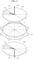
FIG. 4 is a view illustrating a configuration in which the upper and lower gas distribution plates are provided in the cylindrical adsorption reactor when the VOCs removal system according to the embodiment of the present invention has one regeneration zone. -
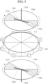
FIG. 5 is a view illustrating a configuration in which the upper and lower gas distribution plates are provided in the cylindrical adsorption reactor when the VOCs removal system according to the embodiment of the present invention has two regeneration zone. -
FIG. 6 is a cross-sectional view of the VOCs removal system according to the embodiment of the present invention. -
FIG. 7 is a view illustrating a configuration in which the VOCs removal system according to the embodiment of the present invention and peripheral facilities are integrated. -
FIG. 8 is a perspective view illustrating a configuration of the microwave module having slotted waveguides installed in one divided zone of the cylindrical reactor according to the embodiment of the present invention. - Hereinafter, a system for removing VOCs using gas distribution plates of the present invention will be described in detail with reference to the accompanying drawings.
- The present invention discloses a system for removing VOCs using gas distribution plates as defined in the claims.
- The present invention is intended to simplify a facility and reduce operation costs by including the rotary type gas distribution plates, which are relatively lighter than the adsorption reactor and the microwave modules.
- The
cylindrical adsorption reactor 110 is filled with an adsorbent 111 including activated carbon, zeolite, and the like so as to adsorb VOCs components in a VOCs-containing gas. In addition, an inside of thecylindrical adsorption reactor 110, which is filled with the adsorbent 111, is radially divided into a plurality of zone based on a central axis. The adsorption reactor having the divided zone therein includes adsorption zone configured to adsorb VOCs in the VOCs-containing gas supplied from an outside, and at least one regeneration zone configured to desorb the VOCs adsorbed in the adsorption zone through a recycled air with a high temperature. In addition, the adsorption reactor may further include a cooling zone in which cooling is performed after the VOCs are desorbed. - The plurality of
microwave modules 120 are disposed at a predetermined interval along the outer periphery of thecylindrical adsorption reactor 110. Preferably, themicrowave module 120 may be disposed on each side, that is, each peripheral surface of the radially divided zone of thecylindrical adsorption reactor 110. - The plurality of
microwave modules 120 are manufactured to be included as a portion of acase 140 which surrounds the peripheral surface of thecylindrical adsorption reactor 110. Thereby, thecase 140 including themicrowave modules 120 may prevent the microwave from being leaked to the outside from the peripheral surface of thecylindrical adsorption reactor 110. When recycling the zone in which themicrowave module 120 is disposed, the microwave module is turned on to irradiate the regeneration zone with microwaves, thus to heat the VOCs-containing gas therein. When the recycling is completed, the microwave module is turned off and an operation of the system is stopped. The peripheral surface of thecylindrical adsorption reactor 110 may be made of amica plate 112 to allow the microwaves to pass through. - The microwave module may employ a method of irradiating the regeneration zone with microwaves through a waveguide. In this case, the waveguide may be formed in an undivided state, that is, may have one passage through which the microwave passes.
- Alternatively, the microwave module 120' may include a
waveguide 170 having a plurality of slots to uniformly divide the passage through which the microwave passes so as to relatively uniformly irradiate the regeneration zone with the microwaves. That is, it may be configured in such a way that, each of the plurality of microwave modules is disposed along the lateral periphery of the radially dividedzone 110 of the cylindrical adsorption reactor, and has thewaveguide 170 including the plurality of slots, so as to uniformly emit the microwaves through the plurality of slots. -
FIG. 8 is a perspective view illustrating the microwave module 120' with theslotted waveguide 170 installed in the lateral periphery of one divided zone of thecylindrical reactor 110. As shown inFIG. 8 , the waveguide may be configured to emit the microwaves from one lateral portion thereof, or emit the microwaves from a central portion thereof. - The rotary gas distribution plate is configured to be disposed on the upper and lower portions of the
cylindrical adsorption reactor 110, respectively. The uppergas distribution plates cylindrical adsorption reactor 110 includesupply pipes cylindrical adsorption reactor 110. The recycled air is supplied to thesupply pipes air inlets gas distribution plates cylindrical adsorption reactor 110 includedischarge pipes cylindrical adsorption reactor 110. Thedischarge pipes air outlets supply pipes gas distribution plates discharge pipes gas distribution plates cylindrical adsorption reactor 110 is projected directly above or below the regeneration zone of thecylindrical adsorption reactor 110, respectively. For the convenience of explanation, zone in which the regeneration zone of thecylindrical adsorption reactor 110 are projected on the uppergas distribution plates upper regeneration zone gas distribution plates lower zone - The upper
gas distribution plates gas distribution plates cylindrical adsorption reactor 110. - When the upper
gas distribution plates gas distribution plates upper regeneration zone lower regeneration zone cylindrical adsorption reactor 110, that is, during thesupply pipes discharge pipes cylindrical adsorption reactor 110 through thesupply pipes microwave module 120 disposed on the sides of the regeneration zone is switched from an operation stop state to an operation state, thereby heating the regeneration zone. As a result, the adsorbed VOCs components are desorbed. The recycled air containing the desorbed VOCs is discharged throughdischarge pipes - The rotation period and recycling time may be adjusted by pre-setting them through a timer or program. That is, the rotation period of the upper and lower
gas distribution plates microwave module 120 may be preset through the timer or program. Therefore, it is possible to easily control the adsorption and desorption time of VOCs. - Alternatively, it may be configured in such a way that, by including sensors, positions of the
upper regeneration zone lower regeneration zone cylindrical adsorption reactor 110 are detected, so as to stop the rotation of the upper and lowergas distribution plates microwave module 120 based on the detected positions. - The region to be recycled at the same time may be one divided regeneration zone or a plurality of regeneration zone radially arranged at a predetermined interval.
FIGS. 2 and4 , andFIGS. 3 and5 are views illustrating a concept in which the upper and lower gas distribution plates are coupled with the cylindrical adsorption reactor in cases of having one regeneration zone and two regeneration zone, respectively. - As such, in order to achieve a single or a plurality of regeneration zone in the
cylindrical adsorption reactor 110, the numbers of thesupply pipes gas distribution plates 130a and thedischarge pipes gas distribution plates supply pipes discharge pipes gas distribution plates - Similar to the regeneration zone, the adsorption zone may be formed in several zone at the same time. As such, the adsorption and desorption processes may be performed in the several zone at the same time, thereby saving energy and installation space of the facility.
- As shown in
FIG. 6 , the VOCs removal system of the present invention further includes anadditional case 150 which surrounds the uppergas distribution plates gas distribution plates microwave modules 120, andcompressed air inlets 160 formed in theadditional case 150. Herein, a degree of adhesion between the upper and lowergas distribution plates cylindrical adsorption reactor 110 is adjusted by injecting or discharging a compressed air through thecompressed air inlets 160. - That is, it is configured in such a way that: the upper
gas distribution plates gas distribution plates cylindrical adsorption reactor 110 during supplying the recycled air to the regeneration zone and maintaining the operation state of themicrowave module 120; and the uppergas distribution plates gas distribution plates cylindrical adsorption reactor 110 when stopping a supply of the recycled air to the regeneration zone and switching themicrowave module 120 to the operation stop state. By injecting and discharging the compressed air into and from the regeneration zone as described above, the degree of adhesion between the upper and lowergas distribution plates cylindrical adsorption reactor 110 can be adjusted. Through such a configuration, the supplied recycled air is prevented from being distributed to the adsorption zone or the cooling zone adjacent to the regeneration zone so as to allow the supplied recycled air to be fully used for a recycling operation. - In order to further enhance the effect of recycling, the cross-sectional areas of the upper
gas distribution plates gas distribution plates cylindrical adsorption reactor 110. -
FIG. 7 is a view illustrating a configuration in which thecylindrical adsorption reactor 110 of the present invention, a catalyst system, and a heat exchanger are integrated. - The VOCs-containing gas is supplied to the adsorption zone from the outside, and VOCs of the VOCs-containing gas are adsorbed thereto. In this case, a fresh air from which the VOCs are removed by adsorption is discharged to the outside.
- As the VOCs-containing recycled air discharged from the regeneration zone passes through a catalytic reactor, the VOCs are desorbed from the regeneration zone and oxidatively decomposed into carbon dioxide and water. That is, in the catalytic reactor, the VOCs are oxidized into carbon dioxide (CO2) and water (H2O) under a heating condition at about 200 to 350°C, in this case, a Pd catalyst, Pt catalyst, Ru catalyst or Rh catalyst may be used as an oxidation catalyst.
- The catalytic reactor of the present invention may be further provided with a separate microwave module to be utilized as a heat source. The desorbed VOCs-containing hot gas is introduced into a body of the catalytic reactor, and absorbs microwaves to be used as a heat source, thereby the VOCs are removed and treated by facilitating the decomposition thereof.
- The hot air containing CO2/H2O passing through the catalytic reactor is subjected to heat exchange in a heat exchanger, a waste heat generated from the catalytic reactor is supplied to the recycled air, which may be recycled as energy for a desorption reaction in the regeneration zone.
- When the adsorption reactor of the present invention includes the cooling zone, after the VOCs are desorbed in the cooling zone, cooling of the adsorption reactor in which the surface temperature is increased by microwaves is performed. At this time, by supplying a cooling air to the cooling zone, the adsorption reactor may be cooled to room temperature. The injected cooling air is converted into a hot air having a temperature of about 50 to 100°C, and similar to the hot air containing CO2/H2O passing through the catalytic reactor, the hot air passing through the cooling zone is also subjected to heat exchange in the heat exchanger, and the waste heat is supplied to the recycled air, which may be recycled as energy for the desorption reaction in the regeneration zone.
- On the other hand, the air cooled while passing through the heat exchanger and CO2/H2O are discharged to the outside.
- As described above, according to the present invention, by fixing the adsorption reactor and the microwave module, which occupy a large part in terms of volume and weight in the VOCs removal system, and by including the gas distribution plates having a relatively lightweight in a rotary type structure, it is possible to simplify a facility and reduce the operation costs. In addition, since the adsorption and desorption time can be easily controlled and the adsorption and desorption processes can be carried out simultaneously in several zone, a single adsorption reactor may achieve effects similar to the effects obtained by several adsorption reactors. Further, since the microwave modules are fixed to the adsorption reactor in terms of the structure thereof, it is possible to prevent the microwave from being leaked to the outside from the peripheral surface of the adsorption reactor. Furthermore, the upper and lower
gas distribution plates
Claims (7)
- A system for removing VOCs using gas distribution plates, comprising:a fixed cylindrical adsorption reactor (110) including an adsorption zone configured to adsorb VOCs and a regeneration zone configured to desorb the VOCs adsorbed in the adsorption zone;a plurality of microwave modules (120) disposed at a predetermined interval along an outer periphery of the cylindrical adsorption reactor (110), the plurality of microwave modules (120) being included as a part of a case (140) which surrounds a peripheral surface of the cylindrical adsorption reactor (110);a rotary upper gas distribution plate (130a) having a supply pipe (133a) configured to supply a recycled air to the regeneration zone and disposed on an upper portion of the cylindrical adsorption reactor (110); anda rotary lower gas distribution plate (130b) having a discharge pipe (133b) configured to discharge the recycled air containing VOCs desorbed from the regeneration zone and disposed on a lower portion of the cylindrical adsorption reactor (110),wherein, when the upper gas distribution plate (130a) and the lower gas distribution plate (130b) rotate, and then the supply pipe and the discharge pipe are located in an upper section and a lower section of the regeneration zone, the recycled air is supplied to the regeneration zone, and at the same time, a microwave module (120) disposed on a peripheral surface of the regeneration zone is switched to an operation state to heat the regeneration zone;an additional case (150) which surrounds the upper gas distribution plate (130a) and the lower gas distribution plate (130b), and the microwave module; andcompressed air inlets (160) formed in the additional case (150),
wherein a degree of adhesion between the upper and lower gas distribution plates and the cylindrical adsorption reactor (110) is adjusted by injecting or discharging a compressed air through the compressed air inlets (160), andwherein the upper gas distribution plate (130a) and the lower gas distribution plate (130b) are in close contact with the cylindrical adsorption reactor (110) during supplying the recycled air to the regeneration zone and maintaining the operation state of the microwave module (120); andthe upper gas distribution plate (130a) and the lower gas distribution plate (130b) are spaced from the cylindrical adsorption reactor (110) when stopping a supply of the recycled air to the regeneration zone and switching the microwave module (120) to an operation stop state. - The system for removing VOCs using gas distribution plates according to claim 1, wherein the cylindrical adsorption reactor (110) has a cross-sectional area coinciding with cross-sectional areas of the upper gas distribution plate (130a) and the lower gas distribution plate (130b).
- The system for removing VOCs using gas distribution plates according to claim 1, wherein the upper gas distribution plate (130a) and the lower gas distribution plate (130b) periodically rotate in the same direction and have the same rotation period as each other.
- The system for removing VOCs using gas distribution plates according to claim 1, wherein a plurality of supply pipes (133a) and discharge pipes (133b) are radially disposed at a predetermined interval about rotation axes of the upper and lower gas distribution plates, thus to achieve a plurality of regeneration zone in the cylindrical adsorption reactor (110).
- The system for removing VOCs using gas distribution plates according to claim 1, further comprising a catalytic reactor configured to oxidize the VOCs desorbed in the regeneration zone.
- The system for removing VOCs using gas distribution plates according to claim 5, further comprising a heat exchanger configured to perform heat exchange on a hot air passing through the catalytic reactor, such that a waste heat generated from the catalytic reactor is supplied to the recycled air.
- The system for removing VOCs using gas distribution plates according to claim 1, wherein each of the plurality of microwave modules (120) has waveguides which are disposed along the outer periphery of the cylindrical adsorption reactor (110), and have a plurality of slots, such that the regeneration zone is uniformly irradiated with microwaves through the plurality of slots.
Applications Claiming Priority (3)
| Application Number | Priority Date | Filing Date | Title |
|---|---|---|---|
| KR20170092815 | 2017-07-21 | ||
| KR1020170105033A KR102406023B1 (en) | 2017-07-21 | 2017-08-18 | SYSTEM FOR REMOVING VOCs USING GAS DISTRIBUTION PLATE |
| PCT/KR2017/013281 WO2019017533A1 (en) | 2017-07-21 | 2017-11-21 | System for removing vocs using gas distribution plate |
Publications (4)
| Publication Number | Publication Date |
|---|---|
| EP3656455A1 EP3656455A1 (en) | 2020-05-27 |
| EP3656455A4 EP3656455A4 (en) | 2021-04-21 |
| EP3656455B1 true EP3656455B1 (en) | 2024-10-09 |
| EP3656455C0 EP3656455C0 (en) | 2024-10-09 |
Family
ID=65323476
Family Applications (1)
| Application Number | Title | Priority Date | Filing Date |
|---|---|---|---|
| EP17918554.1A Active EP3656455B1 (en) | 2017-07-21 | 2017-11-21 | System for removing vocs using gas distribution plate |
Country Status (4)
| Country | Link |
|---|---|
| EP (1) | EP3656455B1 (en) |
| JP (1) | JP6808012B2 (en) |
| KR (1) | KR102406023B1 (en) |
| CN (1) | CN109548400B (en) |
Families Citing this family (6)
| Publication number | Priority date | Publication date | Assignee | Title |
|---|---|---|---|---|
| KR102298040B1 (en) * | 2019-10-18 | 2021-09-06 | 세종대학교 산학협력단 | VOCs adsorption and room temperature catalytic oxidation system |
| KR102360332B1 (en) * | 2019-12-30 | 2022-02-10 | 주식회사 에코프로에이치엔 | Dehumidification system using microwave |
| CN114618258B (en) * | 2020-12-11 | 2024-05-28 | 陕西青朗万城环保科技有限公司 | Rotatable microwave waste gas treatment method and control system thereof |
| KR102456956B1 (en) * | 2020-12-28 | 2022-10-21 | 주식회사 에코프로에이치엔 | Dehumidification system |
| CN118662990B (en) * | 2024-06-21 | 2024-12-27 | 苏州中迈新能源科技有限公司 | Methane vapor deposition waste gas recycling system and method |
| CN118925598B (en) * | 2024-10-11 | 2025-03-04 | 成都同创伟业新能源科技有限公司 | Square structure reactor for producing hydrogen from methanol |
Family Cites Families (12)
| Publication number | Priority date | Publication date | Assignee | Title |
|---|---|---|---|---|
| JP2002028436A (en) * | 2000-07-12 | 2002-01-29 | Daikin Ind Ltd | Deodorizing device |
| JP2010158661A (en) * | 2009-01-12 | 2010-07-22 | Ind Technol Res Inst | Desorption device with low energy consumption and dehumidifying device thereof |
| KR101132597B1 (en) * | 2010-03-19 | 2012-04-06 | 주식회사 엠투 | Heat decomposition filtration system |
| JP2011253653A (en) * | 2010-05-31 | 2011-12-15 | Daikin Ind Ltd | Microwave heating device, microwave heating device using multiple wave guides and adsorption regeneration device |
| CN103133695A (en) * | 2011-11-29 | 2013-06-05 | 天津市天发重型水电设备制造有限公司 | Novel main shaft sealing structure of hydraulic generator |
| JP2013123669A (en) * | 2011-12-14 | 2013-06-24 | Daifuku Co Ltd | Concentration recovery method for concentration recovery object component in treated gas or moisture in treated gas, and concentration recovery apparatus for concentration recovery object component in treated gas or moisture in treated gas using the same |
| KR101323108B1 (en) | 2013-03-18 | 2013-10-30 | 주식회사 에코프로 | Honeycomb rotor type vocs removal system with horizontally polarized microwave radiation |
| KR101476285B1 (en) * | 2013-04-16 | 2014-12-24 | 주식회사 엔바이온 | Air purifying filter with desorption means by microwave heating and air purifying device thereof |
| CN104888242B (en) * | 2015-05-15 | 2018-08-21 | 楚天科技股份有限公司 | A kind of flange sealer and pulse vacuum sterile cabinet |
| KR20160137699A (en) * | 2015-05-20 | 2016-12-01 | 주식회사 라이트브릿지 | Rotation regeneration type deodorization system |
| CN205001245U (en) * | 2015-06-29 | 2016-01-27 | 萧振林 | Novel fan drive connect and be sealed device |
| CN106540509A (en) * | 2016-11-25 | 2017-03-29 | 胡毅强 | Capstan head type micro-wave adsorption/desorption device |
-
2017
- 2017-08-18 KR KR1020170105033A patent/KR102406023B1/en active Active
- 2017-11-21 EP EP17918554.1A patent/EP3656455B1/en active Active
- 2017-11-21 JP JP2019500636A patent/JP6808012B2/en not_active Expired - Fee Related
- 2017-11-21 CN CN201780043457.2A patent/CN109548400B/en active Active
Also Published As
| Publication number | Publication date |
|---|---|
| JP6808012B2 (en) | 2021-01-06 |
| EP3656455A1 (en) | 2020-05-27 |
| JP2019525835A (en) | 2019-09-12 |
| KR20190010856A (en) | 2019-01-31 |
| CN109548400B (en) | 2021-10-26 |
| EP3656455C0 (en) | 2024-10-09 |
| KR102406023B1 (en) | 2022-06-09 |
| EP3656455A4 (en) | 2021-04-21 |
| CN109548400A (en) | 2019-03-29 |
Similar Documents
| Publication | Publication Date | Title |
|---|---|---|
| EP3656455A1 (en) | System for removing vocs using gas distribution plate | |
| EP3892355A1 (en) | Vocs removal system using slotted waveguides | |
| KR102404373B1 (en) | SYSTEM FOR REMOVING VOCs USING SLOTTED WAVEGUIDE | |
| US20160339388A1 (en) | Volatile Organic Compound Removal System Using Microwaves | |
| KR100966481B1 (en) | Moving Bed Continuous Volatility Concentration System and Continuous Concentration Method | |
| KR101323108B1 (en) | Honeycomb rotor type vocs removal system with horizontally polarized microwave radiation | |
| KR20160136988A (en) | SYSTEM FOR REMOVING VOCs USING MICROWAVE | |
| CN209752534U (en) | VOC S removal system utilizing gas distribution plate | |
| KR102298040B1 (en) | VOCs adsorption and room temperature catalytic oxidation system | |
| KR100690441B1 (en) | Volatile Organic Compound Enriched Catalytic Combustion System and Concentrated Bank for the Same | |
| KR100889639B1 (en) | Volatile Organic Compound Processing Equipment | |
| KR20200026400A (en) | MODULARIZED VOCs REMOVAL SYSTEM AND ITS METHOD USING ADSORPTION ROTOR AND OXIDATION CATALYST | |
| KR101354613B1 (en) | Vocs processing system using heating element | |
| KR100784409B1 (en) | Volatile Organic Compound Concentrated Catalytic Combustion System and Method | |
| EP0604198B1 (en) | Method for treating ammonia | |
| KR20130142840A (en) | Apparatus for purifying discharge gas using rotor | |
| CN210522252U (en) | VOCs removing system using groove type wave guide tube | |
| WO2019017533A1 (en) | System for removing vocs using gas distribution plate | |
| KR101529703B1 (en) | Decomposition method for contaminant and Contaminant decomposition apparatus for the same | |
| JP2010201373A (en) | Apparatus for treating gas | |
| CN112237824B (en) | Device for continuously adsorbing and desorbing organic waste gas through built-in heating integration | |
| CN210385360U (en) | Safe and controllable VOC (volatile organic compound) treatment device | |
| KR101404816B1 (en) | Apparatus for Purifying Discharge Gas of Painting System | |
| JPH0684141U (en) | Deodorizer | |
| JP5339134B2 (en) | Gas processing equipment |
Legal Events
| Date | Code | Title | Description |
|---|---|---|---|
| STAA | Information on the status of an ep patent application or granted ep patent |
Free format text: STATUS: THE INTERNATIONAL PUBLICATION HAS BEEN MADE |
|
| PUAI | Public reference made under article 153(3) epc to a published international application that has entered the european phase |
Free format text: ORIGINAL CODE: 0009012 |
|
| STAA | Information on the status of an ep patent application or granted ep patent |
Free format text: STATUS: REQUEST FOR EXAMINATION WAS MADE |
|
| 17P | Request for examination filed |
Effective date: 20200221 |
|
| AK | Designated contracting states |
Kind code of ref document: A1 Designated state(s): AL AT BE BG CH CY CZ DE DK EE ES FI FR GB GR HR HU IE IS IT LI LT LU LV MC MK MT NL NO PL PT RO RS SE SI SK SM TR |
|
| AX | Request for extension of the european patent |
Extension state: BA ME |
|
| DAV | Request for validation of the european patent (deleted) | ||
| DAX | Request for extension of the european patent (deleted) | ||
| A4 | Supplementary search report drawn up and despatched |
Effective date: 20210319 |
|
| RIC1 | Information provided on ipc code assigned before grant |
Ipc: B01D 53/04 20060101AFI20210315BHEP |
|
| RAP1 | Party data changed (applicant data changed or rights of an application transferred) |
Owner name: ECOPROHN CO. LTD. |
|
| STAA | Information on the status of an ep patent application or granted ep patent |
Free format text: STATUS: EXAMINATION IS IN PROGRESS |
|
| 17Q | First examination report despatched |
Effective date: 20221028 |
|
| GRAP | Despatch of communication of intention to grant a patent |
Free format text: ORIGINAL CODE: EPIDOSNIGR1 |
|
| STAA | Information on the status of an ep patent application or granted ep patent |
Free format text: STATUS: GRANT OF PATENT IS INTENDED |
|
| INTG | Intention to grant announced |
Effective date: 20240502 |
|
| GRAS | Grant fee paid |
Free format text: ORIGINAL CODE: EPIDOSNIGR3 |
|
| GRAA | (expected) grant |
Free format text: ORIGINAL CODE: 0009210 |
|
| STAA | Information on the status of an ep patent application or granted ep patent |
Free format text: STATUS: THE PATENT HAS BEEN GRANTED |
|
| AK | Designated contracting states |
Kind code of ref document: B1 Designated state(s): AL AT BE BG CH CY CZ DE DK EE ES FI FR GB GR HR HU IE IS IT LI LT LU LV MC MK MT NL NO PL PT RO RS SE SI SK SM TR |
|
| REG | Reference to a national code |
Ref country code: CH Ref legal event code: EP |
|
| REG | Reference to a national code |
Ref country code: DE Ref legal event code: R096 Ref document number: 602017085451 Country of ref document: DE |
|
| REG | Reference to a national code |
Ref country code: IE Ref legal event code: FG4D |
|
| U01 | Request for unitary effect filed |
Effective date: 20241105 |
|
| U07 | Unitary effect registered |
Designated state(s): AT BE BG DE DK EE FI FR IT LT LU LV MT NL PT RO SE SI Effective date: 20241113 |
|
| U20 | Renewal fee for the european patent with unitary effect paid |
Year of fee payment: 8 Effective date: 20241130 |
|
| PG25 | Lapsed in a contracting state [announced via postgrant information from national office to epo] |
Ref country code: HR Free format text: LAPSE BECAUSE OF FAILURE TO SUBMIT A TRANSLATION OF THE DESCRIPTION OR TO PAY THE FEE WITHIN THE PRESCRIBED TIME-LIMIT Effective date: 20241009 Ref country code: IS Free format text: LAPSE BECAUSE OF FAILURE TO SUBMIT A TRANSLATION OF THE DESCRIPTION OR TO PAY THE FEE WITHIN THE PRESCRIBED TIME-LIMIT Effective date: 20250209 |
|
| PG25 | Lapsed in a contracting state [announced via postgrant information from national office to epo] |
Ref country code: ES Free format text: LAPSE BECAUSE OF FAILURE TO SUBMIT A TRANSLATION OF THE DESCRIPTION OR TO PAY THE FEE WITHIN THE PRESCRIBED TIME-LIMIT Effective date: 20241009 |
|
| PG25 | Lapsed in a contracting state [announced via postgrant information from national office to epo] |
Ref country code: NO Free format text: LAPSE BECAUSE OF FAILURE TO SUBMIT A TRANSLATION OF THE DESCRIPTION OR TO PAY THE FEE WITHIN THE PRESCRIBED TIME-LIMIT Effective date: 20250109 |
|
| PG25 | Lapsed in a contracting state [announced via postgrant information from national office to epo] |
Ref country code: GR Free format text: LAPSE BECAUSE OF FAILURE TO SUBMIT A TRANSLATION OF THE DESCRIPTION OR TO PAY THE FEE WITHIN THE PRESCRIBED TIME-LIMIT Effective date: 20250110 |
|
| PG25 | Lapsed in a contracting state [announced via postgrant information from national office to epo] |
Ref country code: PL Free format text: LAPSE BECAUSE OF FAILURE TO SUBMIT A TRANSLATION OF THE DESCRIPTION OR TO PAY THE FEE WITHIN THE PRESCRIBED TIME-LIMIT Effective date: 20241009 |
|
| PG25 | Lapsed in a contracting state [announced via postgrant information from national office to epo] |
Ref country code: RS Free format text: LAPSE BECAUSE OF FAILURE TO SUBMIT A TRANSLATION OF THE DESCRIPTION OR TO PAY THE FEE WITHIN THE PRESCRIBED TIME-LIMIT Effective date: 20250109 |
|
| REG | Reference to a national code |
Ref country code: CH Ref legal event code: PL |
|
| PG25 | Lapsed in a contracting state [announced via postgrant information from national office to epo] |
Ref country code: SM Free format text: LAPSE BECAUSE OF FAILURE TO SUBMIT A TRANSLATION OF THE DESCRIPTION OR TO PAY THE FEE WITHIN THE PRESCRIBED TIME-LIMIT Effective date: 20241009 |
|
| PG25 | Lapsed in a contracting state [announced via postgrant information from national office to epo] |
Ref country code: MC Free format text: LAPSE BECAUSE OF FAILURE TO SUBMIT A TRANSLATION OF THE DESCRIPTION OR TO PAY THE FEE WITHIN THE PRESCRIBED TIME-LIMIT Effective date: 20241009 |
|
| REG | Reference to a national code |
Ref country code: CH Ref legal event code: PL |
|
| PG25 | Lapsed in a contracting state [announced via postgrant information from national office to epo] |
Ref country code: CH Free format text: LAPSE BECAUSE OF NON-PAYMENT OF DUE FEES Effective date: 20241130 |
|
| PG25 | Lapsed in a contracting state [announced via postgrant information from national office to epo] |
Ref country code: SK Free format text: LAPSE BECAUSE OF FAILURE TO SUBMIT A TRANSLATION OF THE DESCRIPTION OR TO PAY THE FEE WITHIN THE PRESCRIBED TIME-LIMIT Effective date: 20241009 |
|
| PG25 | Lapsed in a contracting state [announced via postgrant information from national office to epo] |
Ref country code: CZ Free format text: LAPSE BECAUSE OF FAILURE TO SUBMIT A TRANSLATION OF THE DESCRIPTION OR TO PAY THE FEE WITHIN THE PRESCRIBED TIME-LIMIT Effective date: 20241009 |
|
| PLBE | No opposition filed within time limit |
Free format text: ORIGINAL CODE: 0009261 |
|
| STAA | Information on the status of an ep patent application or granted ep patent |
Free format text: STATUS: NO OPPOSITION FILED WITHIN TIME LIMIT |
|
| 26N | No opposition filed |
Effective date: 20250710 |
|
| GBPC | Gb: european patent ceased through non-payment of renewal fee |
Effective date: 20250109 |
|
| PG25 | Lapsed in a contracting state [announced via postgrant information from national office to epo] |
Ref country code: GB Free format text: LAPSE BECAUSE OF NON-PAYMENT OF DUE FEES Effective date: 20250109 |
|
| PG25 | Lapsed in a contracting state [announced via postgrant information from national office to epo] |
Ref country code: IE Free format text: LAPSE BECAUSE OF NON-PAYMENT OF DUE FEES Effective date: 20241121 |
|
| PG25 | Lapsed in a contracting state [announced via postgrant information from national office to epo] |
Ref country code: HU Free format text: LAPSE BECAUSE OF FAILURE TO SUBMIT A TRANSLATION OF THE DESCRIPTION OR TO PAY THE FEE WITHIN THE PRESCRIBED TIME-LIMIT; INVALID AB INITIO Effective date: 20171121 |
|
| PG25 | Lapsed in a contracting state [announced via postgrant information from national office to epo] |
Ref country code: CY Free format text: LAPSE BECAUSE OF FAILURE TO SUBMIT A TRANSLATION OF THE DESCRIPTION OR TO PAY THE FEE WITHIN THE PRESCRIBED TIME-LIMIT; INVALID AB INITIO Effective date: 20171121 |