EP3656320B1 - Verankerungselement für eine polyaxiale knochenverankerungsvorrichtung und polyaxiale knochenverankerungsvorrichtung mit solch einem verankerungselement - Google Patents
Verankerungselement für eine polyaxiale knochenverankerungsvorrichtung und polyaxiale knochenverankerungsvorrichtung mit solch einem verankerungselement Download PDFInfo
- Publication number
- EP3656320B1 EP3656320B1 EP18207354.4A EP18207354A EP3656320B1 EP 3656320 B1 EP3656320 B1 EP 3656320B1 EP 18207354 A EP18207354 A EP 18207354A EP 3656320 B1 EP3656320 B1 EP 3656320B1
- Authority
- EP
- European Patent Office
- Prior art keywords
- head
- neck
- anchoring
- anchoring member
- curvature
- Prior art date
- Legal status (The legal status is an assumption and is not a legal conclusion. Google has not performed a legal analysis and makes no representation as to the accuracy of the status listed.)
- Active
Links
- 238000004873 anchoring Methods 0.000 title claims description 135
- 210000000988 bone and bone Anatomy 0.000 title claims description 65
- 230000006641 stabilisation Effects 0.000 claims description 2
- 238000011105 stabilization Methods 0.000 claims description 2
- 230000004323 axial length Effects 0.000 description 7
- 239000004696 Poly ether ether ketone Substances 0.000 description 2
- 208000020307 Spinal disease Diseases 0.000 description 2
- 229910045601 alloy Inorganic materials 0.000 description 2
- 239000000956 alloy Substances 0.000 description 2
- 239000000463 material Substances 0.000 description 2
- 229920001432 poly(L-lactide) Polymers 0.000 description 2
- 229920002530 polyetherether ketone Polymers 0.000 description 2
- 230000007704 transition Effects 0.000 description 2
- 229910001200 Ferrotitanium Inorganic materials 0.000 description 1
- FYYHWMGAXLPEAU-UHFFFAOYSA-N Magnesium Chemical compound [Mg] FYYHWMGAXLPEAU-UHFFFAOYSA-N 0.000 description 1
- 229910000861 Mg alloy Inorganic materials 0.000 description 1
- RTAQQCXQSZGOHL-UHFFFAOYSA-N Titanium Chemical compound [Ti] RTAQQCXQSZGOHL-UHFFFAOYSA-N 0.000 description 1
- 239000002253 acid Substances 0.000 description 1
- 239000000560 biocompatible material Substances 0.000 description 1
- 230000000052 comparative effect Effects 0.000 description 1
- 238000010276 construction Methods 0.000 description 1
- 238000002788 crimping Methods 0.000 description 1
- 230000007423 decrease Effects 0.000 description 1
- 239000007943 implant Substances 0.000 description 1
- 208000014674 injury Diseases 0.000 description 1
- 238000003780 insertion Methods 0.000 description 1
- 230000037431 insertion Effects 0.000 description 1
- 229910052749 magnesium Inorganic materials 0.000 description 1
- 239000011777 magnesium Substances 0.000 description 1
- 238000012986 modification Methods 0.000 description 1
- 230000004048 modification Effects 0.000 description 1
- 229910001000 nickel titanium Inorganic materials 0.000 description 1
- HLXZNVUGXRDIFK-UHFFFAOYSA-N nickel titanium Chemical compound [Ti].[Ti].[Ti].[Ti].[Ti].[Ti].[Ti].[Ti].[Ti].[Ti].[Ti].[Ni].[Ni].[Ni].[Ni].[Ni].[Ni].[Ni].[Ni].[Ni].[Ni].[Ni].[Ni].[Ni].[Ni] HLXZNVUGXRDIFK-UHFFFAOYSA-N 0.000 description 1
- 239000004033 plastic Substances 0.000 description 1
- 229920003023 plastic Polymers 0.000 description 1
- 239000010935 stainless steel Substances 0.000 description 1
- 229910001220 stainless steel Inorganic materials 0.000 description 1
- 238000001356 surgical procedure Methods 0.000 description 1
- 239000010936 titanium Substances 0.000 description 1
- 230000008733 trauma Effects 0.000 description 1
Images


Classifications
-
- A—HUMAN NECESSITIES
- A61—MEDICAL OR VETERINARY SCIENCE; HYGIENE
- A61B—DIAGNOSIS; SURGERY; IDENTIFICATION
- A61B17/00—Surgical instruments, devices or methods, e.g. tourniquets
- A61B17/56—Surgical instruments or methods for treatment of bones or joints; Devices specially adapted therefor
- A61B17/58—Surgical instruments or methods for treatment of bones or joints; Devices specially adapted therefor for osteosynthesis, e.g. bone plates, screws, setting implements or the like
- A61B17/68—Internal fixation devices, including fasteners and spinal fixators, even if a part thereof projects from the skin
- A61B17/70—Spinal positioners or stabilisers ; Bone stabilisers comprising fluid filler in an implant
- A61B17/7001—Screws or hooks combined with longitudinal elements which do not contact vertebrae
- A61B17/7032—Screws or hooks with U-shaped head or back through which longitudinal rods pass
-
- A—HUMAN NECESSITIES
- A61—MEDICAL OR VETERINARY SCIENCE; HYGIENE
- A61B—DIAGNOSIS; SURGERY; IDENTIFICATION
- A61B17/00—Surgical instruments, devices or methods, e.g. tourniquets
- A61B17/56—Surgical instruments or methods for treatment of bones or joints; Devices specially adapted therefor
- A61B17/58—Surgical instruments or methods for treatment of bones or joints; Devices specially adapted therefor for osteosynthesis, e.g. bone plates, screws, setting implements or the like
- A61B17/68—Internal fixation devices, including fasteners and spinal fixators, even if a part thereof projects from the skin
- A61B17/70—Spinal positioners or stabilisers ; Bone stabilisers comprising fluid filler in an implant
- A61B17/7001—Screws or hooks combined with longitudinal elements which do not contact vertebrae
- A61B17/7035—Screws or hooks, wherein a rod-clamping part and a bone-anchoring part can pivot relative to each other
- A61B17/7037—Screws or hooks, wherein a rod-clamping part and a bone-anchoring part can pivot relative to each other wherein pivoting is blocked when the rod is clamped
-
- A—HUMAN NECESSITIES
- A61—MEDICAL OR VETERINARY SCIENCE; HYGIENE
- A61B—DIAGNOSIS; SURGERY; IDENTIFICATION
- A61B17/00—Surgical instruments, devices or methods, e.g. tourniquets
- A61B17/56—Surgical instruments or methods for treatment of bones or joints; Devices specially adapted therefor
- A61B17/58—Surgical instruments or methods for treatment of bones or joints; Devices specially adapted therefor for osteosynthesis, e.g. bone plates, screws, setting implements or the like
- A61B17/68—Internal fixation devices, including fasteners and spinal fixators, even if a part thereof projects from the skin
- A61B17/70—Spinal positioners or stabilisers ; Bone stabilisers comprising fluid filler in an implant
- A61B17/7001—Screws or hooks combined with longitudinal elements which do not contact vertebrae
- A61B17/7035—Screws or hooks, wherein a rod-clamping part and a bone-anchoring part can pivot relative to each other
-
- A—HUMAN NECESSITIES
- A61—MEDICAL OR VETERINARY SCIENCE; HYGIENE
- A61B—DIAGNOSIS; SURGERY; IDENTIFICATION
- A61B17/00—Surgical instruments, devices or methods, e.g. tourniquets
- A61B17/56—Surgical instruments or methods for treatment of bones or joints; Devices specially adapted therefor
- A61B17/58—Surgical instruments or methods for treatment of bones or joints; Devices specially adapted therefor for osteosynthesis, e.g. bone plates, screws, setting implements or the like
- A61B17/68—Internal fixation devices, including fasteners and spinal fixators, even if a part thereof projects from the skin
- A61B17/84—Fasteners therefor or fasteners being internal fixation devices
- A61B17/86—Pins or screws or threaded wires; nuts therefor
- A61B17/8685—Pins or screws or threaded wires; nuts therefor comprising multiple separate parts
-
- A—HUMAN NECESSITIES
- A61—MEDICAL OR VETERINARY SCIENCE; HYGIENE
- A61B—DIAGNOSIS; SURGERY; IDENTIFICATION
- A61B17/00—Surgical instruments, devices or methods, e.g. tourniquets
- A61B17/56—Surgical instruments or methods for treatment of bones or joints; Devices specially adapted therefor
- A61B17/58—Surgical instruments or methods for treatment of bones or joints; Devices specially adapted therefor for osteosynthesis, e.g. bone plates, screws, setting implements or the like
- A61B17/68—Internal fixation devices, including fasteners and spinal fixators, even if a part thereof projects from the skin
- A61B17/70—Spinal positioners or stabilisers ; Bone stabilisers comprising fluid filler in an implant
- A61B17/7059—Cortical plates
-
- A—HUMAN NECESSITIES
- A61—MEDICAL OR VETERINARY SCIENCE; HYGIENE
- A61B—DIAGNOSIS; SURGERY; IDENTIFICATION
- A61B17/00—Surgical instruments, devices or methods, e.g. tourniquets
- A61B17/56—Surgical instruments or methods for treatment of bones or joints; Devices specially adapted therefor
- A61B17/58—Surgical instruments or methods for treatment of bones or joints; Devices specially adapted therefor for osteosynthesis, e.g. bone plates, screws, setting implements or the like
- A61B17/68—Internal fixation devices, including fasteners and spinal fixators, even if a part thereof projects from the skin
- A61B17/84—Fasteners therefor or fasteners being internal fixation devices
- A61B17/86—Pins or screws or threaded wires; nuts therefor
-
- A—HUMAN NECESSITIES
- A61—MEDICAL OR VETERINARY SCIENCE; HYGIENE
- A61B—DIAGNOSIS; SURGERY; IDENTIFICATION
- A61B17/00—Surgical instruments, devices or methods, e.g. tourniquets
- A61B2017/00831—Material properties
-
- A—HUMAN NECESSITIES
- A61—MEDICAL OR VETERINARY SCIENCE; HYGIENE
- A61B—DIAGNOSIS; SURGERY; IDENTIFICATION
- A61B17/00—Surgical instruments, devices or methods, e.g. tourniquets
- A61B2017/00831—Material properties
- A61B2017/00867—Material properties shape memory effect
Definitions
- the invention relates to an anchoring member for a polyaxial bone anchoring device and to a polyaxial bone anchoring device including the anchoring member.
- it is related to devices for the treatment of spinal disorders or for use in trauma surgery.
- US 5,443,467 describes a polyaxial bone anchoring device with an anchoring element comprising a shaft for anchoring in bone and a spherical segment-shaped head wherein the anchoring element is pivotably held in a receiving part that is configured to couple the anchoring element to a spinal rod.
- the portion of the anchoring element between the head and the shaft may be a potential area where the anchoring element may fail under load.
- US 2017/0245894 A1 describes a polyaxial bone anchoring device comprising an anchor body and a fastener that includes a head, a threaded shaft that extends out with respect to the head in a distal direction, and a neck between the head and the threaded shaft.
- the head includes an outer surface at least a portion of which is convex and defines a portion of a sphere that defines a first diameter.
- the neck defines a second diameter and the fastener defines a ratio of the first diameter to the second diameter in a range between about 2 to 1 and about 3 to 1.
- the object is solved by an anchoring member according to claim 1 and by a polyaxial bone anchoring device according to claim 13.
- an anchoring member for a polyaxial bone anchoring device includes a bone anchoring section having a first end, a second end and a bone engagement structure on at least a portion thereof, a head, the head having an outer surface portion that defines a portion of a sphere, a central axis extending through respective centers of the head and the first and second ends of the bone anchoring section and a neck between the first end of the bone anchoring section and the head, the neck including a first portion that is closer to the head than to the bone anchoring section, wherein in at least one plane including the central axis, the first portion of the neck is concave with a first curvature, the neck further including a second portion between the first portion and the bone anchoring section, wherein in the at least one plane, the second portion is concave with a second curvature that is smaller than the first curvature.
- the first portion joins the second portion in an axial direction.
- B means of this design, a transition between the bone anchoring section or a cylindrical portion of the neck and the head is shifted toward a center of the head in the axial direction. Thereby the distribution of loads acting onto the head and/or the neck is improved. As a result, the strength, in particular the fatigue strength, of the anchoring member against breaking, in particular in the region of the neck is increased.
- a polyaxial bone anchoring device includes the bone anchoring member and a receiving part including a seat configured to receive the head such that the bone anchoring section can assume a plurality of angular positions relative to the receiving part.
- a maximum pivot angle that the anchoring member can form relative to the receiving part may be increased compared to an anchoring member that has a substantially cylindrical neck.
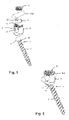
- a polyaxial bone anchoring device includes an anchoring member 1 including a shank 2 for anchoring in a bone or a vertebra and a head 3. Further, a receiving part 4 for pivotably receiving the head 3 of the anchoring member 1 is provided that is configured to couple the anchoring member 1 to a stabilization rod 100. Moreover, a pressure member 5 may be provided to exert pressure onto the head 3 in the receiving part 4 to lock the head 3 in a specific angular position with respect to the receiving part 4. Furthermore, a locking member 6, for example in the form of a set screw, may be part of the bone anchoring device for securing and fixing rod 100 in the receiving part 4.
- the receiving part 4 has a first end or top end 4a and an opposite second end or bottom end 4b, an axis of symmetry M and a coaxial bore 8 extending from the first end 4a in the direction of the second end 4b.
- a substantially U-shaped recess 9 Adjacent to the first end 4a, a substantially U-shaped recess 9 is provided that serves as a channel for receiving the rod 100.
- two free legs are formed which are provided with an engagement structure, such as an internal thread 10, for cooperating with the locking member 6.
- the passage provided by the coaxial bore 8 narrows towards the second end 4b and forms an opening 11 whose inner diameter is of such a size that the anchoring member 1 can be guided through with the shank 2 until the head 3 is seated in a seat 12 adjacent to the opening 11.
- the seat 12 for the head 3 may be designed as a spherical segment-shaped portion that matches an outer surface portion of the head 3.
- the anchoring member 1 comprises a central axis C extending through a center of the head 3 and being coaxial to a longitudinal axis of the shank 2.
- the anchoring member 1 is a monolithic piece.
- the shank 2 has a first end 21 facing the head 3 and an opposite second end 22 that may be shaped as a tip.
- a bone engagement structure 20 for example a bone thread, may be provided on at least a portion of the outer surface of the shank 2.
- the shank 2 forms a bone anchoring section of the anchoring member 1.
- the head 3 comprises a spherically-shaped outer surface portion 31 that defines a sphere S (see Fig.
- the head 3 has such an axial length, that the diameter D 1 of the sphere S forms the largest width of the head 3.
- a section of the sphere S in a plane P that includes the central axis C forms a circle (see for example Fig. 6 ),
- the head 3 comprises a free end surface 32 that may include a recess 3a for engagement with a driver to drive the anchoring element 1 into bone.
- the free end surface 32 may be flat.
- the neck 23 includes a first portion 24 that is closer to the head 3 and a second portion 25 that is closer to the bone anchoring section.
- the first portion 24 has an outer surface that is concave with a first curvature.
- the surface of the first portion 24 of the neck 23 defines a circular segment with a first radius of curvature R 1 .
- the neck 23 and the outer surface portion 31 of the head 3 are rotationally symmetrical around the central axis C.
- the first radius of curvature R 1 of the first portion 24 is the same in every radial direction and therefore in every plane that includes the central axis C.
- an edge 33 is formed.
- the second portion 25 of the neck 23 is also concave with a second curvature smaller than the first curvature.
- the surface of the second portion 25 is less strongly curved than that of the first portion 24.
- the surface of the second portion 25 also defines a circular segment in the plane P with a second radius of curvature R 2 wherein R 2 is greater than R 1 as depicted in Fig. 4 . Due to the rotational symmetry, the second radius of curvature R 2 of the second portion 25 of the neck 23 is the same in every radial direction and therefore in every plane that includes the central axis C. As can be seen in the figures, the first portion 24 continuously merges into the second portion 25
- a diameter D 2 of the neck 23 in a plane perpendicular to the central axis C is at any axial position of the first portion 24 or the second portion 25 smaller than the first diameter D 1 . More specifically, in the second portion 25, the diameter D 2 is such that a ratio D 1 :D 2 is about 7:4. Preferably, the ratio D 1 :D 2 may be between about 1 and less than 2.
- An axial length of the second portion 25 is greater than an axial length of the first portion 24. More specifically, the axial length of the second portion 25 may be twice or more the axial length of the first portion 24.
- a third, cylindrical portion 26 may be provided between the second portion 25 and the shank 2.
- the second portion 25 continuously merges into the cylindrical portion 26.
- An axial length of the third, cylindrical portion 26 may be smaller than an axial length of the second portion 25.
- the outer diameter D 3 of the third cylindrical portion 26 may be the same or slightly greater than a core diameter D C of the shank 2. At the transition between the second portion 25 and the cylindrical portion 26, D 3 may be the same as D 2 .
- the pressure member 5 will be explained referring to Figs. 1 and 5 .
- the pressure member 5 may be formed as a monolithic piece. Is it of substantially cylindrical construction and has an outer diameter that allows it to move in the axial direction within the bore 8 of the receiving part 4.
- the pressure member 5 comprises a substantially spherical recess 51 at its side that faces the head 3 when the pressure member 5 and the head 3 are assembled within the receiving part 4.
- the substantially spherical recess 51 is adapted to the size of the head 3.
- a substantially cylindrically-shaped recess 52 is formed that is configured to receive the rod 100 therein.
- the surface of the rod extends above the sidewalls of the recess 52 when the rod 100 is inserted into the recess 52.
- a coaxial bore 53 formed in the pressure member 5 permits access with a tool such as a driver to the recess 3a in the head 3 when the anchoring member 1 is assembled in the receiving part 4.
- the locking member 6 is comprised of a set screw that can be screwed between the legs of the receiving part 4. It is configured to contact the rod 100 when the rod 100 is inserted into the receiving part 4.
- the anchoring member 1, the receiving part 4, the pressure member 5 and the locking member 6 as well as the rod 100 may each be made of bio-compatible materials, for example of titanium or stainless steel, of a bio-compatible alloy, such as NiTi-alloys, for example Nitinol, of magnesium or magnesium alloys, or from a bio-compatible plastic material, such as, for example polyether ether ketone (PEEK) or poly-L-lactide acid (PLLA).
- PEEK polyether ether ketone
- PLLA poly-L-lactide acid
- the parts can be made of the same as or of different materials from another.
- the polyaxial bone anchoring device may be preassembled with the anchoring member 1 being inserted from the first end 4a into the receiving part 4 until its head 3 rests in the seat 12.
- the pressure member 5 may be rotationally fixed within the receiving part 4, for example, by crimping using crimp bores 54 at the outer surface of the pressure member 5.
- At least two anchoring members 1 with receiving parts 4 are inserted into the bone or in adjacent vertebrae and connected through the rod 100.
- the receiving part 4 may be pivoted relative to the anchoring member 1 to facilitate insertion of the rod 100.
- a maximum pivot angle ⁇ is defined by the abutment of the neck 23 against an edge 11a of the opening 11 of the receiving part 4.
- the sizes of the head 3 and the neck 23 relative to the seat 12 in the receiving part 4 are such that the edge 11a abuts against the second portion 25 of the neck that has the smaller curvature.
- the first portion 24 of the neck 23 preferably is within the seat 12 of the receiving part 4 at the side to which the anchoring member 1 pivots.
- FIG. 8 a comparative example of an anchoring member 101 is shown in which the neck 123 is devoid of any portions that extend into the sphere S defined by the spherical segment-shaped head 103. Comparing the anchoring member of the embodiment according to Fig. 7 with the example of the anchoring member of Fig. 8 , the maximum pivot angle ⁇ is increased when the neck 23 extends into the sphere S as shown in Fig. 7 . Moreover, the strength of the anchoring member 1 of the embodiment shown in Fig. 7 against loads is increased. Ultimately, forces can be distributed in an improved manner between the head 3 and the neck 23.
- the anchoring member 1' differs from the anchoring member 1 of the first embodiment by the shape and size of the head. All other portions are identical or similar and the description thereof will not be repeated. Like portions are provided with the same reference numerals as in the first embodiment.
- the head 3' of the anchoring member 1' has a diameter D 1 ' that may be, compared to the diameter D 2 of the neck 23, greater than the diameter D 1 of the anchoring member 1 of the first embodiment. More specifically, the ratio of D 1 ':D 2 may be between about 1 and about 3.
- the head comprises an undercut portion 34 that extends between the edge 33 and the first portion 24 of the neck 23.
- the undercut portion 34 is recessed from a virtual plane that extends perpendicular to the central axis C and through the outermost point of the edge 33 in the direction towards the free end surface 32.
- the undercut portion 34 is curved in the same manner as the first portion 24 of the neck 23.
- the surface of the undercut portion 34 defines part of the circular segment in the plane P that continues from the second portion 24 to the edge 33.
- the radius of curvature R 1 of the undercut portion 34 and of the first portion 24 of the neck 23 may be the same.
- the undercut portion 34 may also have another shape, for example a noncircular curvature.
- the strength of the anchoring member can be further increased. As illustrated in Fig. 11 , due to the enlarged diameter of the head 3' the maximum pivot angle ⁇ can be further increased.
- a second embodiment of a polyaxial bone anchoring device that comprises a bone plate 200 as a receiving part for the anchoring member 1.
- the bone plate 200 has a first or bone-contacting surface 201 and an opposite second surface 202.
- At least one, preferably more than one through-hole 203 extends from the second surface 202 through the plate to the first surface 201.
- a seat 204 is formed for the head 3 of the anchoring element 1.
- the seat 204 has a shape corresponding to the outer spherical-surface portion of the head 3 so that, as long the bone plate and the anchoring member 1 are not implanted into the body, the anchoring member 1 can pivot within the seat 204 with a maximum pivot angle ⁇ to one side.
- the anchoring member is for example the anchoring member 1 of the first embodiment or may be the anchoring member 1' of the second embodiment. In use, the anchoring member can be inserted into the bone at a specific angle that is delimited by the maximum pivot angle of the polyaxial bone anchoring device. The strength of the anchoring member under load is improved. If necessary, a locking cap (not shown) may be provided in the hole 203 to prevent backing-out of the anchoring member.
- the polyaxial bone anchoring device is not limited to the embodiments shown.
- the anchoring member can be used with any receiving part that provides a seat for the head.
- Such receiving parts can be of the top-loading type, where the anchoring member is inserted from the top of the receiving part or of the bottom-loading type, where the anchoring member is inserted with the head through a lower opening.
- any bone plate or other surgical implant that is combined with an anchoring member of the above described embodiments, forms a polyaxial bone anchoring device according to the invention.
- the seat may have another shape or provided within an insert member that is within the receiving part. Many different polyaxial bone anchoring devices may be conceivable.
- the bone anchoring section may have any bone anchoring structure or shape that is suitable for anchoring in bone or in a vertebra.
- the head may also be non-rotationally symmetrical.
- the head may have two opposite flat surface portions so that the spherical surface portion allows the anchoring member to pivot in the receiving part only in a single plane.
- the symmetry of the neck may correspond to the symmetry of the head.
Landscapes
- Health & Medical Sciences (AREA)
- Orthopedic Medicine & Surgery (AREA)
- Life Sciences & Earth Sciences (AREA)
- Surgery (AREA)
- Neurology (AREA)
- Heart & Thoracic Surgery (AREA)
- Engineering & Computer Science (AREA)
- Biomedical Technology (AREA)
- Nuclear Medicine, Radiotherapy & Molecular Imaging (AREA)
- Medical Informatics (AREA)
- Molecular Biology (AREA)
- Animal Behavior & Ethology (AREA)
- General Health & Medical Sciences (AREA)
- Public Health (AREA)
- Veterinary Medicine (AREA)
- Surgical Instruments (AREA)
Claims (15)
- Verankerungselement für eine polyaxiale Knochenverankerungsvorrichtung, wobei das Verankerungselement (1, 1') umfasst:einen Knochenverankerungsabschnitt (2) mit einem ersten Ende (21), einem zweiten Ende (22) und einer Knocheneingriffsstruktur an zumindest einem Teil davon;einen Kopf (3, 3'), wobei der Kopf einen Außenoberflächen-Abschnitt (31) aufweist, der einen Abschnitt einer Kugel (S) definiert,eine Mittelachse (C), die sich durch jeweilige Mitten des Kopfes (3, 3') und des ersten und zweiten Endes des Knochenverankerungsabschnitts erstreckt undeinen Hals (23) zwischen dem ersten Ende (21) des Knochenverankerungsabschnitts (2) und dem Kopf (3), wobei der Hals (23) einen ersten Abschnitt (24) umfasst, der näher am Kopf (3) liegt als an dem Knochenverankerungsabschnitt (2), wobei in mindestens einer Ebene (P), die die Mittelachse (C) enthält, der erste Abschnitt (24) des Halses (23) konkav mit einer ersten Krümmung ist; dadurch gekennzeichnet,dass der Hals (23) weiter einen zweiten Abschnitt (25) zwischen dem ersten Abschnitt (24) und dem Knochenverankerungsabschnitt (2) umfasst, wobei der zweite Abschnitt (25) in der mindestens einen Ebene (P) konkav mit einer zweiten Krümmung ist, die kleiner als die erste Krümmung ist.
- Verankerungselement nach Anspruch 1, wobei die Kugel (S) in der mindestens einen Ebene (P) einen Kreis definiert und wobei der zweite Abschnitt (25) des Halses (23) zumindest teilweise innerhalb des Kreises liegt.
- Verankerungselement nach Anspruch 2, wobei der erste Abschnitt (24) des Halses (23) vollständig innerhalb des Kreises liegt.
- Verankerungselement nach einem der Ansprüche 1 bis 3, wobei der Hals (23) rotationssymmetrisch um die Mittelachse (C) ist.
- Verankerungselement nach einem der Ansprüche 1 bis 4, wobei der Außenoberflächen-Abschnitt (31) des Kopfes (3, 3') rotationssymmetrisch um die Mittelachse (C) ist.
- Verankerungselement nach einem der Ansprüche 1 bis 5, wobei der erste Abschnitt (24) und der zweite Abschnitt (25) des Halses (23) bei Betrachtung in der Ebene (P) auf einer Seite der Mittelachse (C) kontinuierlich ineinander übergehen.
- Verankerungselement nach einem der Ansprüche 1 bis 5, wobei die erste Krümmung einen ersten Krümmungsradius (R1) aufweist und wobei die zweite Krümmung einen zweiten Krümmungsradius (R2) aufweist, der größer als der erste Krümmungsradius (R1) ist.
- Verankerungselement nach einem der Ansprüche 1 bis 7, wobei zwischen dem ersten Abschnitt (24) des Halses (23) und dem Kopf (3, 3') eine Kante (33) gebildet ist, vorzugsweise eine abgerundete Kante.
- Verankerungselement nach einem der Ansprüche 1 bis 8, wobei an einer dem ersten Abschnitt (24) des Halses zugewandten Seite des Kopfes (3') eine Hinterschneidung (34) ausgebildet ist.
- Verankerungselement nach Anspruch 9, wobei die Hinterschneidung (34) in der Ebene (P) eine dritte Krümmung aufweist, die vorzugsweise gleich der ersten Krümmung ist.
- Verankerungselement nach einem der Ansprüche 1 bis 10, wobei zwischen dem zweiten Abschnitt (25) des Halses (23) und dem Knochenverankerungsabschnitt (2) ein zylindrischer Abschnitt (26) gebildet ist, der in Richtung des Kopfes (3) vorzugsweise kontinuierlich in den zweiten Abschnitt übergeht (25).
- Verankerungselement nach einem der Ansprüche 1 bis 11, wobei die dem Außenoberflächen-Abschnitt (31) des Kopfes (3) zugeordnete Kugel (S) einen ersten Durchmesser (D1) definiert und wobei der Hals (23) in einer Ebene senkrecht zur Mittelachse (C) und vorzugsweise im zweiten Abschnitt (25) des Halses (23) oder nahe dem ersten Ende (21) des Verankerungsabschnitts (2) einen zweiten Durchmesser (D2) aufweist, und wobei ein Verhältnis zwischen dem ersten Durchmesser (D1) und dem zweiten Durchmesser (D2) zwischen ungefähr 1 und kleiner 2 ist, vorzugsweise ungefähr 7:4.
- Polyaxiale Knochenverankerungsvorrichtung, umfassend:das Verankerungselement nach einem der Ansprüche 1 bis 12; undein Aufnahmeteil (4; 200), das einen Sitz (12, 204) umfasst, der so ausgebildet ist, dass er den Kopf (3, 3') so aufnimmt, dass der Knochenverankerungsabschnitt (2) eine Mehrzahl von Winkelpositionen relativ zu dem Aufnahmeteil (4) einnehmen kann.
- Polyaxiale Knochenverankerungsvorrichtung nach Anspruch 13, wobei das Aufnahmeteil (4) eine Stabaufnahmeausnehmung (9) umfasst, die dazu ausgebildet ist, ein längliches Stabilisierungselement wie z.B. einen Wirbelsäulenstab (100) aufzunehmen, oder wobei das Aufnahmeteil als eine Knochenplatte (200) mit zumindest einem Loch (203), das zur Aufnahme des Kopfes (3) ausgebildet ist, gebildet ist.
- Polyaxiale Knochenverankerungsvorrichtung nach Anspruch 13 oder 14, wobei der Sitz (12, 204) des Aufnahmeteils (4, 200) einen sphärischen Oberflächenabschnitt umfasst, der dem sphärischen Oberflächenabschnitt (31) des Kopfs (3) derart entspricht, dass er den Kopf (3) stützt, und wobei zumindest ein Teil des zweiten Abschnitts (25) des Halses (23) innerhalb einer Kugel liegt, die durch den sphärischen Oberflächenabschnitt des Sitzes (12, 204) definiert ist, wenn das Verankerungselement (1, 1') gegenüber dem Aufnahmeteil einen maximalen Schwenkwinkel einnimmt.
Priority Applications (6)
| Application Number | Priority Date | Filing Date | Title |
|---|---|---|---|
| EP18207354.4A EP3656320B1 (de) | 2018-11-20 | 2018-11-20 | Verankerungselement für eine polyaxiale knochenverankerungsvorrichtung und polyaxiale knochenverankerungsvorrichtung mit solch einem verankerungselement |
| CN201911115838.4A CN111195149B (zh) | 2018-11-20 | 2019-11-15 | 多轴骨锚固装置的锚固构件和带该构件的多轴骨锚固装置 |
| JP2019206624A JP7458169B2 (ja) | 2018-11-20 | 2019-11-15 | 多軸骨固定装置用固定部材、および当該固定部材を備えた多軸骨固定装置 |
| US16/686,714 US11284922B2 (en) | 2018-11-20 | 2019-11-18 | Anchoring member for a polyaxial bone anchoring device and polyaxial bone anchoring device with such an anchoring member |
| US17/665,837 US20220226025A1 (en) | 2018-11-20 | 2022-02-07 | Anchoring member for a polyaxial bone anchoring device and polyaxial bone anchoring device with such an anchoring member |
| JP2024004551A JP2024038395A (ja) | 2018-11-20 | 2024-01-16 | 多軸骨固定装置用固定部材、および当該固定部材を備えた多軸骨固定装置 |
Applications Claiming Priority (1)
| Application Number | Priority Date | Filing Date | Title |
|---|---|---|---|
| EP18207354.4A EP3656320B1 (de) | 2018-11-20 | 2018-11-20 | Verankerungselement für eine polyaxiale knochenverankerungsvorrichtung und polyaxiale knochenverankerungsvorrichtung mit solch einem verankerungselement |
Publications (2)
| Publication Number | Publication Date |
|---|---|
| EP3656320A1 EP3656320A1 (de) | 2020-05-27 |
| EP3656320B1 true EP3656320B1 (de) | 2022-08-24 |
Family
ID=64402139
Family Applications (1)
| Application Number | Title | Priority Date | Filing Date |
|---|---|---|---|
| EP18207354.4A Active EP3656320B1 (de) | 2018-11-20 | 2018-11-20 | Verankerungselement für eine polyaxiale knochenverankerungsvorrichtung und polyaxiale knochenverankerungsvorrichtung mit solch einem verankerungselement |
Country Status (4)
| Country | Link |
|---|---|
| US (2) | US11284922B2 (de) |
| EP (1) | EP3656320B1 (de) |
| JP (2) | JP7458169B2 (de) |
| CN (1) | CN111195149B (de) |
Families Citing this family (3)
| Publication number | Priority date | Publication date | Assignee | Title |
|---|---|---|---|---|
| EP3656320B1 (de) * | 2018-11-20 | 2022-08-24 | Biedermann Technologies GmbH & Co. KG | Verankerungselement für eine polyaxiale knochenverankerungsvorrichtung und polyaxiale knochenverankerungsvorrichtung mit solch einem verankerungselement |
| USD956233S1 (en) * | 2020-04-24 | 2022-06-28 | Solco Biomedical Co., Ltd. | Cervical screw |
| USD1037845S1 (en) * | 2022-11-08 | 2024-08-06 | Madhu Sudan Saini | Screw |
Family Cites Families (17)
| Publication number | Priority date | Publication date | Assignee | Title |
|---|---|---|---|---|
| DE4307576C1 (de) | 1993-03-10 | 1994-04-21 | Biedermann Motech Gmbh | Knochenschraube |
| US8353932B2 (en) | 2005-09-30 | 2013-01-15 | Jackson Roger P | Polyaxial bone anchor assembly with one-piece closure, pressure insert and plastic elongate member |
| US7879075B2 (en) * | 2002-02-13 | 2011-02-01 | Zimmer Spine, Inc. | Methods for connecting a longitudinal member to a bone portion |
| US8814911B2 (en) * | 2003-06-18 | 2014-08-26 | Roger P. Jackson | Polyaxial bone screw with cam connection and lock and release insert |
| US20110040338A1 (en) * | 2003-08-28 | 2011-02-17 | Jackson Roger P | Polyaxial bone anchor having an open retainer with conical, cylindrical or curvate capture |
| US7776067B2 (en) * | 2005-05-27 | 2010-08-17 | Jackson Roger P | Polyaxial bone screw with shank articulation pressure insert and method |
| US9439681B2 (en) * | 2007-07-20 | 2016-09-13 | DePuy Synthes Products, Inc. | Polyaxial bone fixation element |
| PL2170192T3 (pl) | 2007-07-20 | 2011-07-29 | Synthes Gmbh | Wieloosiowy przyrząd do stabilizacji kości |
| US8814919B2 (en) * | 2007-10-23 | 2014-08-26 | K2M, Inc. | Posterior pedicle screw having a taper lock |
| US8029539B2 (en) * | 2007-12-19 | 2011-10-04 | X-Spine Systems, Inc. | Offset multiaxial or polyaxial screw, system and assembly |
| US8506601B2 (en) * | 2008-10-14 | 2013-08-13 | Pioneer Surgical Technology, Inc. | Low profile dual locking fixation system and offset anchor member |
| US8808335B2 (en) | 2010-03-08 | 2014-08-19 | Miami Device Solutions, Llc | Locking element for a polyaxial bone anchor, bone plate assembly and tool |
| ES2556462T3 (es) * | 2012-12-10 | 2016-01-18 | Biedermann Technologies Gmbh & Co. Kg | Elemento de anclaje adecuado para ser utilizado en un dispositivo de anclaje de hueso poliaxial y dispositivo de anclaje de hueso poliaxial con un ángulo de giro ampliado hacia un lado |
| US10058354B2 (en) * | 2013-01-28 | 2018-08-28 | Roger P. Jackson | Pivotal bone anchor assembly with frictional shank head seating surfaces |
| US9549765B2 (en) | 2014-04-03 | 2017-01-24 | Zimmer Spine, Inc. | Uniplanar bone screw |
| JP6965257B2 (ja) * | 2016-02-26 | 2021-11-10 | メドス・インターナショナル・エスエイアールエルMedos International SARL | 多軸式骨固定要素 |
| EP3656320B1 (de) * | 2018-11-20 | 2022-08-24 | Biedermann Technologies GmbH & Co. KG | Verankerungselement für eine polyaxiale knochenverankerungsvorrichtung und polyaxiale knochenverankerungsvorrichtung mit solch einem verankerungselement |
-
2018
- 2018-11-20 EP EP18207354.4A patent/EP3656320B1/de active Active
-
2019
- 2019-11-15 JP JP2019206624A patent/JP7458169B2/ja active Active
- 2019-11-15 CN CN201911115838.4A patent/CN111195149B/zh active Active
- 2019-11-18 US US16/686,714 patent/US11284922B2/en active Active
-
2022
- 2022-02-07 US US17/665,837 patent/US20220226025A1/en active Pending
-
2024
- 2024-01-16 JP JP2024004551A patent/JP2024038395A/ja active Pending
Also Published As
| Publication number | Publication date |
|---|---|
| US20220226025A1 (en) | 2022-07-21 |
| US11284922B2 (en) | 2022-03-29 |
| EP3656320A1 (de) | 2020-05-27 |
| CN111195149A (zh) | 2020-05-26 |
| JP2024038395A (ja) | 2024-03-19 |
| CN111195149B (zh) | 2024-06-04 |
| JP2020081871A (ja) | 2020-06-04 |
| US20200155203A1 (en) | 2020-05-21 |
| JP7458169B2 (ja) | 2024-03-29 |
Similar Documents
| Publication | Publication Date | Title |
|---|---|---|
| US12076053B2 (en) | Polyaxial bone anchoring device with enlarged pivot angle | |
| US11925396B2 (en) | Locking element for a polyaxial bone anchor, bone plate assembly and tool | |
| EP1774919B1 (de) | In nur einer Ebene schwenkbare Polyaxialschraube | |
| US20220226025A1 (en) | Anchoring member for a polyaxial bone anchoring device and polyaxial bone anchoring device with such an anchoring member | |
| US9277938B2 (en) | Polyaxial bone anchoring system | |
| EP2559390A1 (de) | Mehrachsige Knochenverankerungsvorrichtung mit vergrößertem Schwenkwinkel | |
| EP2604204B1 (de) | Monoplanare Knochenverankerungsvorrichtung mit auswählbarer Schwenkebene | |
| US20210282819A1 (en) | Coupling device for use with a bone anchoring element and bone anchoring device with such a coupling device | |
| US20220395299A1 (en) | Bone anchoring device |
Legal Events
| Date | Code | Title | Description |
|---|---|---|---|
| PUAI | Public reference made under article 153(3) epc to a published international application that has entered the european phase |
Free format text: ORIGINAL CODE: 0009012 |
|
| STAA | Information on the status of an ep patent application or granted ep patent |
Free format text: STATUS: REQUEST FOR EXAMINATION WAS MADE |
|
| 17P | Request for examination filed |
Effective date: 20191009 |
|
| AK | Designated contracting states |
Kind code of ref document: A1 Designated state(s): AL AT BE BG CH CY CZ DE DK EE ES FI FR GB GR HR HU IE IS IT LI LT LU LV MC MK MT NL NO PL PT RO RS SE SI SK SM TR |
|
| AX | Request for extension of the european patent |
Extension state: BA ME |
|
| RIC1 | Information provided on ipc code assigned before grant |
Ipc: A61B 17/86 20060101ALN20211221BHEP Ipc: A61B 17/70 20060101AFI20211221BHEP |
|
| GRAP | Despatch of communication of intention to grant a patent |
Free format text: ORIGINAL CODE: EPIDOSNIGR1 |
|
| STAA | Information on the status of an ep patent application or granted ep patent |
Free format text: STATUS: GRANT OF PATENT IS INTENDED |
|
| INTG | Intention to grant announced |
Effective date: 20220223 |
|
| GRAJ | Information related to disapproval of communication of intention to grant by the applicant or resumption of examination proceedings by the epo deleted |
Free format text: ORIGINAL CODE: EPIDOSDIGR1 |
|
| STAA | Information on the status of an ep patent application or granted ep patent |
Free format text: STATUS: REQUEST FOR EXAMINATION WAS MADE |
|
| INTC | Intention to grant announced (deleted) | ||
| RIC1 | Information provided on ipc code assigned before grant |
Ipc: A61B 17/86 20060101ALN20220505BHEP Ipc: A61B 17/70 20060101AFI20220505BHEP |
|
| GRAP | Despatch of communication of intention to grant a patent |
Free format text: ORIGINAL CODE: EPIDOSNIGR1 |
|
| STAA | Information on the status of an ep patent application or granted ep patent |
Free format text: STATUS: GRANT OF PATENT IS INTENDED |
|
| GRAS | Grant fee paid |
Free format text: ORIGINAL CODE: EPIDOSNIGR3 |
|
| GRAA | (expected) grant |
Free format text: ORIGINAL CODE: 0009210 |
|
| STAA | Information on the status of an ep patent application or granted ep patent |
Free format text: STATUS: THE PATENT HAS BEEN GRANTED |
|
| INTG | Intention to grant announced |
Effective date: 20220708 |
|
| AK | Designated contracting states |
Kind code of ref document: B1 Designated state(s): AL AT BE BG CH CY CZ DE DK EE ES FI FR GB GR HR HU IE IS IT LI LT LU LV MC MK MT NL NO PL PT RO RS SE SI SK SM TR |
|
| REG | Reference to a national code |
Ref country code: CH Ref legal event code: EP |
|
| REG | Reference to a national code |
Ref country code: DE Ref legal event code: R096 Ref document number: 602018039634 Country of ref document: DE |
|
| REG | Reference to a national code |
Ref country code: IE Ref legal event code: FG4D |
|
| REG | Reference to a national code |
Ref country code: AT Ref legal event code: REF Ref document number: 1513130 Country of ref document: AT Kind code of ref document: T Effective date: 20220915 |
|
| REG | Reference to a national code |
Ref country code: LT Ref legal event code: MG9D |
|
| REG | Reference to a national code |
Ref country code: NL Ref legal event code: MP Effective date: 20220824 |
|
| PG25 | Lapsed in a contracting state [announced via postgrant information from national office to epo] |
Ref country code: SE Free format text: LAPSE BECAUSE OF FAILURE TO SUBMIT A TRANSLATION OF THE DESCRIPTION OR TO PAY THE FEE WITHIN THE PRESCRIBED TIME-LIMIT Effective date: 20220824 Ref country code: RS Free format text: LAPSE BECAUSE OF FAILURE TO SUBMIT A TRANSLATION OF THE DESCRIPTION OR TO PAY THE FEE WITHIN THE PRESCRIBED TIME-LIMIT Effective date: 20220824 Ref country code: PT Free format text: LAPSE BECAUSE OF FAILURE TO SUBMIT A TRANSLATION OF THE DESCRIPTION OR TO PAY THE FEE WITHIN THE PRESCRIBED TIME-LIMIT Effective date: 20221226 Ref country code: NO Free format text: LAPSE BECAUSE OF FAILURE TO SUBMIT A TRANSLATION OF THE DESCRIPTION OR TO PAY THE FEE WITHIN THE PRESCRIBED TIME-LIMIT Effective date: 20221124 Ref country code: NL Free format text: LAPSE BECAUSE OF FAILURE TO SUBMIT A TRANSLATION OF THE DESCRIPTION OR TO PAY THE FEE WITHIN THE PRESCRIBED TIME-LIMIT Effective date: 20220824 Ref country code: LV Free format text: LAPSE BECAUSE OF FAILURE TO SUBMIT A TRANSLATION OF THE DESCRIPTION OR TO PAY THE FEE WITHIN THE PRESCRIBED TIME-LIMIT Effective date: 20220824 Ref country code: LT Free format text: LAPSE BECAUSE OF FAILURE TO SUBMIT A TRANSLATION OF THE DESCRIPTION OR TO PAY THE FEE WITHIN THE PRESCRIBED TIME-LIMIT Effective date: 20220824 Ref country code: FI Free format text: LAPSE BECAUSE OF FAILURE TO SUBMIT A TRANSLATION OF THE DESCRIPTION OR TO PAY THE FEE WITHIN THE PRESCRIBED TIME-LIMIT Effective date: 20220824 |
|
| REG | Reference to a national code |
Ref country code: AT Ref legal event code: MK05 Ref document number: 1513130 Country of ref document: AT Kind code of ref document: T Effective date: 20220824 |
|
| PG25 | Lapsed in a contracting state [announced via postgrant information from national office to epo] |
Ref country code: PL Free format text: LAPSE BECAUSE OF FAILURE TO SUBMIT A TRANSLATION OF THE DESCRIPTION OR TO PAY THE FEE WITHIN THE PRESCRIBED TIME-LIMIT Effective date: 20220824 Ref country code: IS Free format text: LAPSE BECAUSE OF FAILURE TO SUBMIT A TRANSLATION OF THE DESCRIPTION OR TO PAY THE FEE WITHIN THE PRESCRIBED TIME-LIMIT Effective date: 20221224 Ref country code: HR Free format text: LAPSE BECAUSE OF FAILURE TO SUBMIT A TRANSLATION OF THE DESCRIPTION OR TO PAY THE FEE WITHIN THE PRESCRIBED TIME-LIMIT Effective date: 20220824 Ref country code: GR Free format text: LAPSE BECAUSE OF FAILURE TO SUBMIT A TRANSLATION OF THE DESCRIPTION OR TO PAY THE FEE WITHIN THE PRESCRIBED TIME-LIMIT Effective date: 20221125 |
|
| PG25 | Lapsed in a contracting state [announced via postgrant information from national office to epo] |
Ref country code: SM Free format text: LAPSE BECAUSE OF FAILURE TO SUBMIT A TRANSLATION OF THE DESCRIPTION OR TO PAY THE FEE WITHIN THE PRESCRIBED TIME-LIMIT Effective date: 20220824 Ref country code: RO Free format text: LAPSE BECAUSE OF FAILURE TO SUBMIT A TRANSLATION OF THE DESCRIPTION OR TO PAY THE FEE WITHIN THE PRESCRIBED TIME-LIMIT Effective date: 20220824 Ref country code: ES Free format text: LAPSE BECAUSE OF FAILURE TO SUBMIT A TRANSLATION OF THE DESCRIPTION OR TO PAY THE FEE WITHIN THE PRESCRIBED TIME-LIMIT Effective date: 20220824 Ref country code: DK Free format text: LAPSE BECAUSE OF FAILURE TO SUBMIT A TRANSLATION OF THE DESCRIPTION OR TO PAY THE FEE WITHIN THE PRESCRIBED TIME-LIMIT Effective date: 20220824 Ref country code: CZ Free format text: LAPSE BECAUSE OF FAILURE TO SUBMIT A TRANSLATION OF THE DESCRIPTION OR TO PAY THE FEE WITHIN THE PRESCRIBED TIME-LIMIT Effective date: 20220824 Ref country code: AT Free format text: LAPSE BECAUSE OF FAILURE TO SUBMIT A TRANSLATION OF THE DESCRIPTION OR TO PAY THE FEE WITHIN THE PRESCRIBED TIME-LIMIT Effective date: 20220824 |
|
| REG | Reference to a national code |
Ref country code: DE Ref legal event code: R097 Ref document number: 602018039634 Country of ref document: DE |
|
| PG25 | Lapsed in a contracting state [announced via postgrant information from national office to epo] |
Ref country code: SK Free format text: LAPSE BECAUSE OF FAILURE TO SUBMIT A TRANSLATION OF THE DESCRIPTION OR TO PAY THE FEE WITHIN THE PRESCRIBED TIME-LIMIT Effective date: 20220824 Ref country code: EE Free format text: LAPSE BECAUSE OF FAILURE TO SUBMIT A TRANSLATION OF THE DESCRIPTION OR TO PAY THE FEE WITHIN THE PRESCRIBED TIME-LIMIT Effective date: 20220824 |
|
| PG25 | Lapsed in a contracting state [announced via postgrant information from national office to epo] |
Ref country code: MC Free format text: LAPSE BECAUSE OF FAILURE TO SUBMIT A TRANSLATION OF THE DESCRIPTION OR TO PAY THE FEE WITHIN THE PRESCRIBED TIME-LIMIT Effective date: 20220824 Ref country code: AL Free format text: LAPSE BECAUSE OF FAILURE TO SUBMIT A TRANSLATION OF THE DESCRIPTION OR TO PAY THE FEE WITHIN THE PRESCRIBED TIME-LIMIT Effective date: 20220824 |
|
| PLBE | No opposition filed within time limit |
Free format text: ORIGINAL CODE: 0009261 |
|
| STAA | Information on the status of an ep patent application or granted ep patent |
Free format text: STATUS: NO OPPOSITION FILED WITHIN TIME LIMIT |
|
| P01 | Opt-out of the competence of the unified patent court (upc) registered |
Effective date: 20230525 |
|
| REG | Reference to a national code |
Ref country code: BE Ref legal event code: MM Effective date: 20221130 |
|
| 26N | No opposition filed |
Effective date: 20230525 |
|
| PG25 | Lapsed in a contracting state [announced via postgrant information from national office to epo] |
Ref country code: SI Free format text: LAPSE BECAUSE OF FAILURE TO SUBMIT A TRANSLATION OF THE DESCRIPTION OR TO PAY THE FEE WITHIN THE PRESCRIBED TIME-LIMIT Effective date: 20220824 Ref country code: LU Free format text: LAPSE BECAUSE OF NON-PAYMENT OF DUE FEES Effective date: 20221120 |
|
| PG25 | Lapsed in a contracting state [announced via postgrant information from national office to epo] |
Ref country code: IE Free format text: LAPSE BECAUSE OF NON-PAYMENT OF DUE FEES Effective date: 20221120 |
|
| PG25 | Lapsed in a contracting state [announced via postgrant information from national office to epo] |
Ref country code: FR Free format text: LAPSE BECAUSE OF NON-PAYMENT OF DUE FEES Effective date: 20221130 Ref country code: BE Free format text: LAPSE BECAUSE OF NON-PAYMENT OF DUE FEES Effective date: 20221130 |
|
| PGFP | Annual fee paid to national office [announced via postgrant information from national office to epo] |
Ref country code: GB Payment date: 20231123 Year of fee payment: 6 |
|
| PGFP | Annual fee paid to national office [announced via postgrant information from national office to epo] |
Ref country code: DE Payment date: 20231128 Year of fee payment: 6 Ref country code: CH Payment date: 20231202 Year of fee payment: 6 |
|
| PG25 | Lapsed in a contracting state [announced via postgrant information from national office to epo] |
Ref country code: HU Free format text: LAPSE BECAUSE OF FAILURE TO SUBMIT A TRANSLATION OF THE DESCRIPTION OR TO PAY THE FEE WITHIN THE PRESCRIBED TIME-LIMIT; INVALID AB INITIO Effective date: 20181120 |
|
| PG25 | Lapsed in a contracting state [announced via postgrant information from national office to epo] |
Ref country code: CY Free format text: LAPSE BECAUSE OF FAILURE TO SUBMIT A TRANSLATION OF THE DESCRIPTION OR TO PAY THE FEE WITHIN THE PRESCRIBED TIME-LIMIT Effective date: 20220824 |
|
| PG25 | Lapsed in a contracting state [announced via postgrant information from national office to epo] |
Ref country code: MK Free format text: LAPSE BECAUSE OF FAILURE TO SUBMIT A TRANSLATION OF THE DESCRIPTION OR TO PAY THE FEE WITHIN THE PRESCRIBED TIME-LIMIT Effective date: 20220824 Ref country code: IT Free format text: LAPSE BECAUSE OF FAILURE TO SUBMIT A TRANSLATION OF THE DESCRIPTION OR TO PAY THE FEE WITHIN THE PRESCRIBED TIME-LIMIT Effective date: 20220824 |
|
| PG25 | Lapsed in a contracting state [announced via postgrant information from national office to epo] |
Ref country code: BG Free format text: LAPSE BECAUSE OF FAILURE TO SUBMIT A TRANSLATION OF THE DESCRIPTION OR TO PAY THE FEE WITHIN THE PRESCRIBED TIME-LIMIT Effective date: 20220824 |
|
| PG25 | Lapsed in a contracting state [announced via postgrant information from national office to epo] |
Ref country code: MT Free format text: LAPSE BECAUSE OF FAILURE TO SUBMIT A TRANSLATION OF THE DESCRIPTION OR TO PAY THE FEE WITHIN THE PRESCRIBED TIME-LIMIT Effective date: 20220824 |