EP3656264B1 - Verbesserungen an oder im zusammenhang mit einer dusche - Google Patents
Verbesserungen an oder im zusammenhang mit einer dusche Download PDFInfo
- Publication number
- EP3656264B1 EP3656264B1 EP19177768.9A EP19177768A EP3656264B1 EP 3656264 B1 EP3656264 B1 EP 3656264B1 EP 19177768 A EP19177768 A EP 19177768A EP 3656264 B1 EP3656264 B1 EP 3656264B1
- Authority
- EP
- European Patent Office
- Prior art keywords
- shower
- screen
- panel
- pivot
- pivot device
- Prior art date
- Legal status (The legal status is an assumption and is not a legal conclusion. Google has not performed a legal analysis and makes no representation as to the accuracy of the status listed.)
- Active
Links
Images



Classifications
-
- A—HUMAN NECESSITIES
- A47—FURNITURE; DOMESTIC ARTICLES OR APPLIANCES; COFFEE MILLS; SPICE MILLS; SUCTION CLEANERS IN GENERAL
- A47K—SANITARY EQUIPMENT; ACCESSORIES THEREFOR, e.g. TOILET ACCESSORIES
- A47K3/00—Baths; Showers; Appurtenances therefor
- A47K3/28—Showers or bathing douches
- A47K3/30—Screens or collapsible cabinets for showers or baths
-
- A—HUMAN NECESSITIES
- A47—FURNITURE; DOMESTIC ARTICLES OR APPLIANCES; COFFEE MILLS; SPICE MILLS; SUCTION CLEANERS IN GENERAL
- A47K—SANITARY EQUIPMENT; ACCESSORIES THEREFOR, e.g. TOILET ACCESSORIES
- A47K3/00—Baths; Showers; Appurtenances therefor
- A47K3/28—Showers or bathing douches
- A47K3/283—Fixed showers
- A47K3/284—Pre-fabricated shower cabinets
-
- A—HUMAN NECESSITIES
- A47—FURNITURE; DOMESTIC ARTICLES OR APPLIANCES; COFFEE MILLS; SPICE MILLS; SUCTION CLEANERS IN GENERAL
- A47K—SANITARY EQUIPMENT; ACCESSORIES THEREFOR, e.g. TOILET ACCESSORIES
- A47K3/00—Baths; Showers; Appurtenances therefor
- A47K3/28—Showers or bathing douches
- A47K3/30—Screens or collapsible cabinets for showers or baths
- A47K3/36—Articulated screens
-
- A—HUMAN NECESSITIES
- A47—FURNITURE; DOMESTIC ARTICLES OR APPLIANCES; COFFEE MILLS; SPICE MILLS; SUCTION CLEANERS IN GENERAL
- A47K—SANITARY EQUIPMENT; ACCESSORIES THEREFOR, e.g. TOILET ACCESSORIES
- A47K3/00—Baths; Showers; Appurtenances therefor
- A47K3/28—Showers or bathing douches
- A47K3/30—Screens or collapsible cabinets for showers or baths
- A47K2003/305—Sealings between screen and bath- or showertub
-
- A—HUMAN NECESSITIES
- A47—FURNITURE; DOMESTIC ARTICLES OR APPLIANCES; COFFEE MILLS; SPICE MILLS; SUCTION CLEANERS IN GENERAL
- A47K—SANITARY EQUIPMENT; ACCESSORIES THEREFOR, e.g. TOILET ACCESSORIES
- A47K3/00—Baths; Showers; Appurtenances therefor
- A47K3/28—Showers or bathing douches
- A47K3/30—Screens or collapsible cabinets for showers or baths
- A47K3/32—Collapsible cabinets
-
- E—FIXED CONSTRUCTIONS
- E05—LOCKS; KEYS; WINDOW OR DOOR FITTINGS; SAFES
- E05D—HINGES OR SUSPENSION DEVICES FOR DOORS, WINDOWS OR WINGS
- E05D1/00—Pinless hinges; Substitutes for hinges
- E05D1/04—Pinless hinges; Substitutes for hinges with guide members shaped as circular arcs
-
- E—FIXED CONSTRUCTIONS
- E05—LOCKS; KEYS; WINDOW OR DOOR FITTINGS; SAFES
- E05Y—INDEXING SCHEME ASSOCIATED WITH SUBCLASSES E05D AND E05F, RELATING TO CONSTRUCTION ELEMENTS, ELECTRIC CONTROL, POWER SUPPLY, POWER SIGNAL OR TRANSMISSION, USER INTERFACES, MOUNTING OR COUPLING, DETAILS, ACCESSORIES, AUXILIARY OPERATIONS NOT OTHERWISE PROVIDED FOR, APPLICATION THEREOF
- E05Y2900/00—Application of doors, windows, wings or fittings thereof
- E05Y2900/10—Application of doors, windows, wings or fittings thereof for buildings or parts thereof
- E05Y2900/114—Application of doors, windows, wings or fittings thereof for buildings or parts thereof for showers
Definitions
- the present invention relates to a shower-screen pivot device, to a shower comprising such a device (not claimed), and to a method of assisting, preferably single-person, installation of a shower screen.
- the showering area may be formed either by a shower tray which is placed on or recessed into the floor of the bathroom, or by a wet floor which is formed by a tiled or plastics covered flooring having a predetermined fall to a runoff-water drainage outlet.
- a shower screen will often be erected to contain the runoff shower water, particularly to prevent or limit splashing and spraying across the rest of the bathroom.
- the present invention seeks to provide a solution to this problem.
- a shower-screen pivot device comprising a seating element mountable to a shower surface, and a screen-support element for supporting at least part of a shower screen, the seating element having a first panel-pivot element and the screen-support element having a second panel-pivot element which is engagable with the first panel-pivot element, so that, when interengaged, the first and second panel-pivot elements are rotatable relative to each other about a panel-pivot axis which is parallel to a base of the seating element and characterized in that the screen-support element has a depending front wall having an inner surface and a depending back wall having a shorter lateral extent than the front wall, the inner surface of the front wall automatically engaging with a sealing element interposed between the first and second panel-pivot elements, when the seating element and the screen-support element rotate relative to each other to adopt a dead centre, non-rotated, or aligned condition.
- At least one of the first or second panel-pivot elements includes a part-cylindrical surface, and the other of the first or second panel-pivot elements is laterally slidable on the part-cylindrical surface.
- the pivot device may further comprise, when the part-cylindrical surface is on the first panel-pivot element, a fastener-access opening partway therealong.
- the said other of the first or second panel-pivot elements may conveniently include a channel in which the part-cylindrical surface is receivable.
- the part-cylindrical surface or similar forms a saddle or seat which allows the opposing panel-pivot element, when seated thereon, to ride, glide or otherwise slide thereacross as it rotates thereover.
- the part-cylindrical surface can be discontinuous along its length to allow access to mechanical fastening means, such as a screw or bolt, for securing the pivot device to the water-receiving surface or a surround thereof.
- the present arrangement is particularly beneficial in that the lower part of the pivot device can be sealingly engaged with the mounting surface of the shower try or wet floor, and then, as the panel is erected, an additional watertight seal is further created between the two parts of the device.
- the sealing element is preferably carried by the first panel-pivot element at or adjacent to an inwardly-facing side wall thereof. This conveniently enables the upper part to slide into watertight engagement with the lower part, as rotation completes and the two parts align in an in-use configuration.
- the first panel-pivot element may include a recess for accommodating the back wall of the screen-support element.
- the different drops of the front and back walls or skirts accommodate the relative rotation of the two parts of the pivot device, whilst also allowing a flush or substantially flush inside edge or stop at or closely adjacent to the surface of the shower tray or wet floor.
- a marginal return or slight undercut is formed in the lower part.
- the surface extends beyond an equatorial line of a lateral cross-section of the seating element in order to provide the recess that can at least in part receive a lowermost edge of the back wall or back skirt of the upper part.
- the back wall may be canted to be spaced from the said recess of the first panel-pivot element, when the first and second panel-pivot elements are centred relative to each other.
- the back wall or skirt is optionally profiled, having an outward splay or lateral curve along its longitudinal extent. This accommodates an outer, typically curved surface, of the lower part of the pivot device which, together with the above-described recess or undercut, permits a greater degree of rotation movement of the screen-support element or upper part relative to the seating element or bottom part.
- the front wall is preferably at or adjacent to a plane of the base of the seating element.
- a user cannot easily observe the seating element, which may be deemed unsightly, enables a further barrier to water egress from the shower tray or wet floor, enables a neat and uniform finished appearance, and permits a watertight seal to be achieved at a rear of the front wall or front skirt.
- a shower-screen pivot device which is preferably in the form of a kit of parts.
- the pivot device may be provided in part-assembled, for example, with the screen-support element being pre-installed by the manufacturer on a lower edge of the shower-screen panel, the device may also come entirely separately and disassembled. This thus enables easy storage and transport, whereby the device may be entirely assembled purely on-site.
- a method of assisting installation of a shower screen preferably using a shower-screen pivot device in accordance with the first aspect of the invention, the method comprising the steps of: a] providing a shower-screen pivot device having a panel-pivot axis which is parallel to a shower surface, the shower-screen pivot device being interposed between a first panel of the shower screen and the shower surface; b] tilting the first panel away from vertical whilst maintaining engagement via the shower-screen pivot device, so as to rest the tilted first panel against an upright element at or adjacent to the shower surface; c] mounting a second panel of the shower screen to the shower surface; and d] pivoting the tilted first panel back towards vertical via the shower-screen pivot device to enable engagement with the second panel.
- the second panel of the shower screen may be mounted to the shower surface via the or another said shower-screen pivot device, the second panel being tiltable away from the vertical whilst maintaining engagement via said the or another shower-screen pivot device, so as to be restable against the or another upright element at or adjacent to the shower surface.
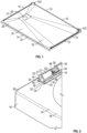
- a shower-screen pivot device 10 which comprises a seating element 12, and a screen-support element 14 which, in this embodiment, is separate or separable from the seating element 12.
- the two parts may be pivotably fastened to each other, for example, by utilising inter-hinged end caps.
- Both the seating element 12 and the screen-support element 14 may beneficially be rigid or substantially rigid elongate members, and conveniently may be extruded from metal, plastics or another suitable material, or a composite thereof.
- a benefit of having the seating element 12 and the screen-support element 14 extruded is to allow a length to be cut or sectioned on-site according to an installation requirement. Bespoke tailoring using a cutting tool by an installer to match or correspond to a side dimension of a shower tray 16 or wet floor within a showering area, such as a bathroom, is thus accommodated.
- the seating element 12 includes a support body 18 having a mounting base 20 at an in-use lower side thereof and a first panel-pivot element 22 at an in-use upper side thereof.
- the mounting base 20 in this case is arranged to provide two flat linear edges 24 to mount to a waste-water runoff surface 26 of the showering area.
- a waste-water runoff surface 26 is typically horizontal or substantially horizontal, and may provide a slight inwardly directed pitch to create a predetermined fall towards a waste-water drain 28 formed or located within the waste-water runoff surface 26.
- the waste-water runoff surface 26 may include a generally raised perimeter edge 30 that surrounds a main user-support portion 32 on which a user usually stands during use of an associated shower head.
- the mounting base 20 is adapted to flushly seat on an upper surface 34 of such a raised perimeter edge 30 with little to no gap between the upper surface 34 and the two flat linear edges 24, thereby minimising or eliminating water ingress therebeneath.
- the waste-water runoff surface may simply be a waterproof plastics covering or tiled covering, for example, having a predetermined flat and/or fall to a discharge drain and on which a user stands during washing.
- the two edges 24 of the mounting base 20 are preferably planar and linear, they may be curved or include more than one linear length to accommodate different shapes and design of shower tray or wet floor, or a particular, potentially irregular, configuration of the bathroom.
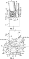
- the first panel-pivot element 22 includes a part-cylindrical surface 36 which extends in parallel with the mounting base 20 along all or substantially all of a longitudinal extent of the support body 18.
- the part-cylindrical surface 36 forms an upper convex dome defining a curved articulating surface 38 across at least part, and in this case a majority, of a lateral extent of the seating element 12.
- the part-cylindrical surface 36 meets an outer side wall 40 of the support body 18 at a position which is preferably beyond an equatorial line E.
- the outer side wall 40 is slightly recessed or can be said to provide an undercut 42 along one side of the seating element 12, as best seen in Figure 4 .
- the outer edge 44 of the said two edges 24 of the mounting base 20 may be formed as a leg 44a with an out-turned foot 44b. This enables improved bracing, along with better weight and pressure distribution.
- the inner edge 46 of the two edges 24 of the mounting base 20 may have a similar leg and foot design. However, it has been found that a single depending leg 46a without an out-turned foot is sufficient, due to only outward pivoting being typically required in most circumstances. However, it will be understood that, by mirroring the design on the inside, two-way pivoting can be accommodated, or by reversing the shower-screen pivot device 10, inward-only pivoting can be provided as opposed to outward-only pivoting.
- An inner side wall 48 of the support body 18 preferably includes a user-facing sealing element 50.
- the sealing element 50 may beneficially be an elongate elastomeric or rubber strip having, for example, a circular lateral cross-section along at least a majority of its longitudinal extent.
- the inner side wall 48 is advantageously provided with a projecting seating channel 52 having marginally in-turned outer edges 52a, 52b and/or walls.
- a width of an opening to the projecting seating channel 52 between the in-turned outer edges 52a, 52b and/or walls is just smaller than a diameter of the sealing element 50.
- a depth of the projecting seating channel 52 is just larger than a radius of the sealing element 50.
- the bottom wall 54 is preferably raised relative to the outer edge 44 and the inner edge 46.
- the support body 18 is thus preferably hollow, defining a tube with an open interior cavity 56 therealong, in addition to a void or space 58 between the outer edge 44, inner edge 46 and bottom wall 54 to accommodate a settable sealant which prevents or limits the passing of runoff waste shower water.
- the part-cylindrical surface 36 of the first panel-pivot element 22 may include one or more fastener-access openings 60 spaced-apart therealong.
- Such fastener-access openings 60 may be preformed through the part-cylindrical surface 36, which is therefore a discontinuous articulating surface, and/or may be formable by an installer as necessity dictates.
- the material of the seating element 12 may be cut by a suitable tool, such as a drill, knife or saw.
- one or more guide lines may be included, and/or such markings or indications may be formed by a removal of a portion of the material of the seating element 12 thus providing weakened portions enabling easier cutting and/or a marginal trough to prevent or limit undesirable wandering of the cutting device.
- the fastener-access opening 60 permits access to the bottom wall 54 of the support body 18, thus allowing a screw-threaded fastener 62 to be inserted therethrough. This permits the option of providing the seating element 12 with a positive mechanical connection to the shower tray 16, wet floor or other washing surface, in addition to the use of sealant.
- the screen-support element 14 includes a second panel-pivot element 64 having a pivot channel 66 in which the part-cylindrical surface 36 is receivable.
- the pivot channel 66 which faces downwardly when in use, is dimensioned to seat and pivot, rotate or slide laterally on the part-cylindrical surface 36.
- the screen-support element 14 further includes a depending front wall 68 forming a first side wall 70 of the pivot channel 66, and a depending back wall 72 forming a second side wall 74 of the pivot channel 66.
- An upper surface 76 of the second panel-pivot element 64 extends from the first side wall 70 to the second side wall 74, thereby forming a cross-channel wall 78 of the pivot channel 66 and closing one longitudinal side of the pivot channel 66 whilst leaving the opposing longitudinal side open to receive the screen-support element 14.
- the depending front wall 68 forming the first side wall 70 of the pivot channel 66, preferably has a longer lateral extent than the depending back wall 72 that forms the second side wall 74.
- the greater width of the first side wall 70 enables automatic engagement of an inner surface 80 thereof with the sealing element 50 as the two parts 12, 14, being the seating element 12 and the screen-support element 14, of the pivot device 10 rotate relative to each other to adopt a dead centre, non-rotated, or aligned condition.
- a drop or lateral extent of the depending front wall 68 terminates at or adjacent to a plane X, shown in Figure 9 , of the mounting base 20 of the seating element 12, such that an in-use lowermost longitudinal edge 82 of the depending front wall 68 forms a vertical stop due to engagement or impingement with a mounting surface of the shower tray 16 or wet floor. This prevents or limits the screen-support element 14 from over-rotating towards the user support area of the shower installation, and consequently beyond or much beyond the vertical.
- the depending front wall 68 which in-use faces the user of the shower, presents a flush or substantially flush finish between the pivot device 10 and the shower tray 16 or wet-floor. Consequently, the flush finish also has the benefit of inhibiting runoff waste water flow into and beneath the pivot device 10.
- the depending back wall 72 is preferably canted, so to allow a gap to the recessed outer side wall 40 of the seating element 12.
- a lateral profile of the depending back wall 72 is, at least in part, partially arcuate or curved to accommodate the part-cylindrical surface 36 of the seating element 12.
- a panel channel 84 is formed along an upper portion of the screen-support element 14.
- the panel channel 84 opposes the pivot channel 66, being in back-to-back relationship and thus contiguous with a common shared wall, in this case being the aforementioned cross-channel wall 78.
- the panel channel 84 includes an upright front wall 86 which extends from the cross-channel wall 78 and contiguously with the depending front wall 68, and an upright back wall 88 which extends also from the cross-channel wall 78 and contiguously with the depending back wall 72.
- the upright back wall 88 upstands with a greater lateral extent than the upright front wall 86, to better brace a panel when pivoted.
- an inner surface of one or both of the upright front wall 86 and the upright back wall 88 may include one or more longitudinal channels and/or ridges, protrusions or other gripping means 90.
- a lateral extent of the panel channel 84 is sufficient to receive a shower-screen panel 92 as a slidable fit.
- a fit may be a tolerance or interference push-fit, and/or may include suitable gaps, spaces or voids for a sealant or other bonding agent to be utilised therein.
- it may be beneficial to include one or more ribs, channels or other spacing means 94 in or on an in-use upper surface 96 of the cross-channel wall 78 to enable improved sealing and/or retainment. Refer to Figure 4 .
- two laterally spaced-apart rotation guides 98 are provided, preferably being depending legs or ribs 100.
- Each leg or rib 100 in this embodiment, may conveniently be continuous and linear, extending at least a majority of a longitudinal extent of the screen-support element 14.
- a first one of the ribs 100a being closer to the depending front wall 68, may project or depend to a greater depth or width than a second one of the ribs 100b.
- the first rib 100a may also be spaced further from the depending front wall 68 than the second rib 100b from the depending back wall 72. This is due to the incorporation of the sealing element 50.
- the deeper first rib 100a forms a more stable longitudinal pivot mounting with the depending back wall 72 as the two interengaged parts, being the seating element 12 and the screen-support element 14, slide laterally relative to each other.
- a pivot axis P which is parallel to the mounting base 20 of the seating element 12 is thus defined by the pivot device 10, once the screen-support element 14 is seated on the seating element 12.
- first and second ribs 100a, 100b may be chamfered or angled to better accommodate the part-cylindrical surface 36 of the first-panel pivot element.
- the shower-screen pivot device 10 is typically transported to the installation site as a kit or in separated part form. Once on site, and with the shower tray 16 or wet floor in place, the seating element 12 of the pivot device 10 is first mounted to a horizontal or substantially horizontal user-support shower surface of the shower tray 16 or wet floor. As explained above, for a shower tray 16, the seating element 12 is typically bonded using a waterproof or water-resistant sealant located between the two legs 44, 46 of the mounting base 20 to a perimeter edge 30, ledge, flange, rim portion or raised surface thereof, along with being engaged with a corner mounting block 102.
- An upright panel support 104 is mounted to the corner mounting block 102, and a lowermost edge 106 of the shower-screen panel 92 is inserted into the panel channel 84 of the screen-support element 14.
- the panel channel 84 may include an adhesive or sealant to fasten and/or seal the shower-screen panel 92 within the panel channel 84.
- the shower-screen panel 92 once engaged with the screen-support element 14, can be seated on the seating element 12.
- the first and second panel-pivot elements 22, 64 are interengaged via the location of the part-cylindrical surface 36 being accommodated within the lower channel to contact the depending first and second ribs 100a, 100b.
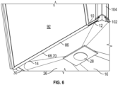
- the installer can thus safely pivot the mounted shower-screen panel 92, whilst it is spaced from the upright panel support 104, about the longitudinal pivot axis P and as a result away from the vertical.
- the installer can then attend, in a similar manner, to any other shower-screen panel 92a around the perimeter of the shower tray 16 or wet floor.
- each shower-screen panel 92, 92a can return each shower-screen panel 92, 92a in turn to its upright or vertical condition, and, if required, slide it longitudinally to an install position, as seen when comparing Figures 6 and 8 .
- Connection and watertight sealing in the normal way to an associated upright panel support 104, neighbouring shower-screen panel 92, 92a, and/or panel connector interposed between adjacent shower-screen panels can thus take place.
- first panel-pivot element 22 includes a part-cylindrical surface 36 to accommodate articulation of the second panel-pivot element 64
- first and second ribs may be provided on the first panel-pivot element and the part-cylindrical surface may be provided on the second panel-pivot element.
- part-cylindrical surface 36 defines a convex or domed sliding surface, it may define a concave or dished sliding surface on either of the parts.
- sealing element 50 may beneficially be carried by the seating element 12, it or a further sealing element may be carried by the depending front wall.
- fastener-access openings 60 are described above. However, an adhesive may solely be used to connect the seating element to the shower surface. As such, the fastener-access openings 60, in certain embodiments, may be omitted.
- the screen-support element 14 is separate and independent of the shower-screen panel 92, it is potentially feasible that the screen-support element could be formed integrally as one-piece with the shower-screen panel at or along a lowermost edge thereof.
- the panel channel of the screen-support element may not be required, and the pivot channel may be formed from the material of the shower-screen panel itself, for example, in the lowermost edge of the panel.
- a shower-screen pivot device which assists, particularly but not necessarily exclusively, single user installation of a shower screen, particularly one having multiple sections or parts. It is also possible to provide a shower-screen pivot device which automatically seals against runoff shower-water ingress into the pivot device, as the two parts of the pivot device are brought into centred, vertical and/or non-pivoted alignment. Furthermore, watertight sealing of the shower panels at or adjacent to their lowermost edges can take place by the installer, before fully erecting and interconnecting the panels.
Landscapes
- Health & Medical Sciences (AREA)
- Public Health (AREA)
- Epidemiology (AREA)
- General Health & Medical Sciences (AREA)
- Bathtubs, Showers, And Their Attachments (AREA)
Claims (11)
- Duschabtrennungsschwenkvorrichtung (10), umfassend ein Auflageelement (12), das an einer Duschenfläche montierbar ist, und ein Abtrennungsstützelement (14) zum Stützen von mindestens einem Teil einer Duschabtrennung, wobei das Auflageelement (12) ein erstes Scheibenschwenkelement (22) aufweist und das Abtrennungsstützelement (14) ein zweites Scheibenschwenkelement (64) aufweist, das mit dem ersten Scheibenschwenkelement (22) in Eingriff gebracht werden kann, so dass, wenn sie ineinandergreifen, das erste und das zweite Scheibenschwenkelement (22, 64) relativ zueinander um eine Scheibenschwenkachse drehbar sind, die parallel zu einer Basis des Auflageelements (12) ist, und dadurch gekennzeichnet, dass das Abtrennungsstützelement (14) eine abhängige Vorderwand (68) mit einer Innenfläche (80) und eine abhängige Rückwand (72) mit einer kürzeren seitlichen Erstreckung als die Vorderwand (68) aufweist, wobei die Innenfläche (80) der Vorderwand (68) automatisch mit dem Auflageelement (50) in Eingriff tritt, zwischen dem ersten und dem zweiten Scheibenschwenkelement (22, 64) eingeschoben, wenn das Auflageelement (12) und das Scheibentrageelement (14) sich relativ zueinander drehen, um einen genau mittigen, nicht gedrehten oder ausgerichteten Zustand anzunehmen.
- Duschabtrennungsschwenkvorrichtung (10) nach Anspruch 1, wobei mindestens eines von dem ersten oder dem zweiten Scheibenschwenkelement (22, 64) eine zum Teil zylindrische Fläche (36) beinhaltet und das andere von dem ersten oder dem zweiten Scheibenschwenkelement (22, 64) auf der zum Teil zylindrischen Fläche (36) seitlich verschiebbar ist.
- Duschabtrennungsschwenkvorrichtung (10) nach Anspruch 2, weiterhin umfassend, wenn die zum Teil zylindrische Fläche (36) sich auf dem ersten Scheibenschwenkelement (22) befindet, eine Befestigungselementzugangsöffnung (60) auf halbem Weg dort entlang.
- Duschabtrennungsschwenkvorrichtung (10) nach Anspruch 2 oder Anspruch 3, wobei das andere von dem ersten oder dem zweiten Scheibenschwenkelement (22, 64) einen Kanal (66) beinhaltet, in dem die zum Teil zylindrische Fläche (36) aufgenommen werden kann.
- Duschabtrennungsschwenkvorrichtung (10) nach einem der vorhergehenden Ansprüche, wobei das Auflageelement (50) von dem ersten Scheibenschwenkelement (22) an einer oder angrenzend an eine nach innen weisende Seitenwand (48) davon getragen wird.
- Duschabtrennungsschwenkvorrichtung (10) nach einem der vorhergehenden Ansprüche, wobei das erste Scheibenschwenkelement (22) eine Aussparung zum Unterbringen der Rückwand (72) des Abtrennungsstützelements (14) beinhaltet.
- Duschabtrennungsschwenkvorrichtung (10) nach Anspruch 6, wobei die Rückwand (72) schräg gestellt ist, um von der Aussparung des ersten Scheibenschwenkelements (22) beabstandet zu sein, wenn das erste und das zweite Scheibenschwenkelement (22, 64) relativ zueinander zentriert sind.
- Duschabtrennungsschwenkvorrichtung (10) nach einem der vorhergehenden Ansprüche, wobei, wenn das erste und das zweite Scheibenschwenkelement (22, 64) relativ zueinander zentriert sind, die Vorderwand (68) sich an einer oder angrenzend an eine Ebene der Basis des Auflageelements (12) befindet.
- Duschabtrennungsschwenkvorrichtung (10) nach einem der vorhergehenden Ansprüche in der Form eines Baukastensystems.
- Verfahren zur Unterstützung einer Installation der Duschabtrennung unter Verwendung einer Duschabtrennungsschwenkvorrichtung (10) nach einem der Ansprüche 1 bis 9, wobei das Verfahren die Schritte umfasst: a] Bereitstellen einer Duschabtrennungsschwenkvorrichtung (10) mit einer Scheibenschwenkachse, die parallel zu einer Duschenfläche ist, wobei die Duschabtrennungsschwenkvorrichtung (10) zwischen einer ersten Scheibe (92) der Duschabtrennung und der Duschenfläche eingeschoben wird, b] Neigen der ersten Scheibe (92) von der Vertikalen weg, während ein Eingriff mittels der Duschabtrennungsschwenkvorrichtung (10) aufrechterhalten wird, um die geneigte erste Scheibe (92) gegen ein senkrechtes Element (104) an der oder angrenzend an die Duschenfläche zu lehnen, c] Montieren einer zweiten Scheibe (92a) der Duschabtrennung an der Duschenfläche und d] Schwenken der geneigten ersten Scheibe (92) zurück zu der Vertikalen mittels der Duschabtrennungsschwenkvorrichtung (10), um einen Eingriff mit der zweiten Scheibe (92a) zu ermöglichen.
- Verfahren nach Anspruch 10, wobei in Schritt c] die zweite Scheibe (92a) der Duschabtrennung an der Duschenfläche mittels der oder einer anderen Duschabtrennungsschwenkvorrichtung (10) montiert wird, wobei die zweite Scheibe (92a) von der Vertikalen weg neigbar ist, während ein Eingriff mittels der oder der andern Duschabtrennungsschwenkvorrichtung (10) aufrechterhalten wird, um gegen das oder ein anderes senkrechtes Element (104) an der oder angrenzend an die Duschenfläche lehnbar zu sein.
Applications Claiming Priority (1)
| Application Number | Priority Date | Filing Date | Title |
|---|---|---|---|
| GB1818893.8A GB2579088A (en) | 2018-11-20 | 2018-11-20 | Improvements in or relating to a shower |
Publications (3)
| Publication Number | Publication Date |
|---|---|
| EP3656264A1 EP3656264A1 (de) | 2020-05-27 |
| EP3656264C0 EP3656264C0 (de) | 2023-10-18 |
| EP3656264B1 true EP3656264B1 (de) | 2023-10-18 |
Family
ID=64740046
Family Applications (1)
| Application Number | Title | Priority Date | Filing Date |
|---|---|---|---|
| EP19177768.9A Active EP3656264B1 (de) | 2018-11-20 | 2019-05-31 | Verbesserungen an oder im zusammenhang mit einer dusche |
Country Status (3)
| Country | Link |
|---|---|
| US (1) | US11253108B2 (de) |
| EP (1) | EP3656264B1 (de) |
| GB (1) | GB2579088A (de) |
Families Citing this family (4)
| Publication number | Priority date | Publication date | Assignee | Title |
|---|---|---|---|---|
| USD912788S1 (en) * | 2019-03-04 | 2021-03-09 | MTI Baths, Inc. | Shower base |
| USD926949S1 (en) * | 2020-01-23 | 2021-08-03 | MTI Baths, Inc. | Shower base |
| CN112932295B (zh) * | 2021-03-09 | 2024-10-25 | 苏州工业园区服务外包职业学院 | 伸缩式坐浴装置及淋浴房 |
| JP2023095561A (ja) * | 2021-12-24 | 2023-07-06 | 株式会社東海理化電機製作所 | 整流装置 |
Family Cites Families (17)
| Publication number | Priority date | Publication date | Assignee | Title |
|---|---|---|---|---|
| US3418665A (en) * | 1966-02-23 | 1968-12-31 | John C. Long | Shower installations |
| US3952463A (en) * | 1974-05-29 | 1976-04-27 | General Aluminum Products, Inc. | Flexible cover support structure |
| DE7539749U (de) * | 1975-12-13 | 1976-04-08 | Oni-Metallwarenfabriken Guenter & Co, 4973 Vlotho | Duschkabinenentür |
| GB8813190D0 (en) * | 1988-06-03 | 1988-07-06 | Alumplast Ltd | Shower screens |
| US5070550A (en) * | 1990-01-16 | 1991-12-10 | Reeves Eric W | Shower closure |
| US5332021A (en) * | 1991-09-11 | 1994-07-26 | Todd John M | Flexible retractable door |
| ATE151612T1 (de) * | 1991-11-12 | 1997-05-15 | Del Castillo Amancio Revuelta | Badewannenschirm |
| US5365619A (en) * | 1994-02-09 | 1994-11-22 | Jeff Solomon | Bathtub shield arrangement |
| US5662069A (en) * | 1995-09-21 | 1997-09-02 | Smith; Leonard | Animal bathing apparatus |
| US6148451A (en) * | 1999-04-14 | 2000-11-21 | Kohler Co. | Shower door attachment assembly |
| DE10207024A1 (de) * | 2002-02-20 | 2003-08-28 | Artweger Gmbh & Co | Dusche |
| FR2896144B1 (fr) * | 2006-01-16 | 2008-02-22 | Aquaproduction Soc Par Actions | Dispositif d'etancheite simplifie, pour le montage de parois de cabines de douche, sur des receveurs du marche |
| GB2462583B (en) * | 2008-07-30 | 2012-08-29 | Dlp Ltd | Hinge assembly for panels with toothed elements |
| US8332972B2 (en) * | 2008-09-11 | 2012-12-18 | Kohler Co. | Plumbing enclosure with easy to assemble components |
| US9974415B2 (en) * | 2015-01-19 | 2018-05-22 | Kohler Co. | Shower door assemblies and methods for installing same |
| US9743810B2 (en) * | 2015-07-31 | 2017-08-29 | Liberty Hardware Mfg. Corp. | Shower door guide assembly |
| CN208346731U (zh) * | 2018-05-17 | 2019-01-08 | 宁波欧贝特卫浴有限公司 | 一种便捷式淋浴房 |
-
2018
- 2018-11-20 GB GB1818893.8A patent/GB2579088A/en not_active Withdrawn
-
2019
- 2019-05-31 EP EP19177768.9A patent/EP3656264B1/de active Active
- 2019-11-20 US US16/689,470 patent/US11253108B2/en not_active Expired - Fee Related
Also Published As
| Publication number | Publication date |
|---|---|
| EP3656264C0 (de) | 2023-10-18 |
| EP3656264A1 (de) | 2020-05-27 |
| US11253108B2 (en) | 2022-02-22 |
| US20200154952A1 (en) | 2020-05-21 |
| GB2579088A (en) | 2020-06-10 |
| GB201818893D0 (en) | 2019-01-02 |
Similar Documents
| Publication | Publication Date | Title |
|---|---|---|
| US11253108B2 (en) | Shower | |
| EP2146014B1 (de) | Höhenverstellbarer Bodenablauf | |
| CA2481076C (en) | A shower tray | |
| US11536016B2 (en) | Floor drain | |
| US12458180B2 (en) | Shower installations and methods for efficiently constructing same | |
| CA2904635C (en) | Level entry shower system | |
| US20130276226A1 (en) | Molded ready-to-tile shower bases with associated trenches and drains | |
| US20100281612A1 (en) | Waterproof juncture | |
| DK1782721T3 (en) | Shower Tray element with gutter | |
| US20100319281A1 (en) | Floor Through Assembly with Adjustable Drain | |
| US10053851B2 (en) | Adjustable drain | |
| WO2010030319A1 (en) | Plumbing enclosure with easy to assemble components | |
| IE930798A1 (en) | Shower tray | |
| JPH10201656A (ja) | シャワー設備用のウォータートラップ | |
| US5383240A (en) | Adjustable trim strips for bathroom fixtures | |
| AU2018241063B2 (en) | Shower base | |
| GB2320068A (en) | A seal between inclined surfaces | |
| GB2421179A (en) | Shower cubicle | |
| US12507833B2 (en) | Shower curb system | |
| GB2231897A (en) | Gutter mounting assembly | |
| US20250341083A1 (en) | Adjustable height bathtub and shower drain assembly | |
| AU785196B2 (en) | Shower base | |
| JPH0638940Y2 (ja) | トイレ用床パン | |
| AU2007203171A1 (en) | Shower tray | |
| AU2004240249B2 (en) | A shower tray |
Legal Events
| Date | Code | Title | Description |
|---|---|---|---|
| PUAI | Public reference made under article 153(3) epc to a published international application that has entered the european phase |
Free format text: ORIGINAL CODE: 0009012 |
|
| STAA | Information on the status of an ep patent application or granted ep patent |
Free format text: STATUS: THE APPLICATION HAS BEEN PUBLISHED |
|
| AK | Designated contracting states |
Kind code of ref document: A1 Designated state(s): AL AT BE BG CH CY CZ DE DK EE ES FI FR GB GR HR HU IE IS IT LI LT LU LV MC MK MT NL NO PL PT RO RS SE SI SK SM TR |
|
| AX | Request for extension of the european patent |
Extension state: BA ME |
|
| STAA | Information on the status of an ep patent application or granted ep patent |
Free format text: STATUS: REQUEST FOR EXAMINATION WAS MADE |
|
| 17P | Request for examination filed |
Effective date: 20201113 |
|
| RBV | Designated contracting states (corrected) |
Designated state(s): AL AT BE BG CH CY CZ DE DK EE ES FI FR GB GR HR HU IE IS IT LI LT LU LV MC MK MT NL NO PL PT RO RS SE SI SK SM TR |
|
| STAA | Information on the status of an ep patent application or granted ep patent |
Free format text: STATUS: EXAMINATION IS IN PROGRESS |
|
| 17Q | First examination report despatched |
Effective date: 20220425 |
|
| GRAP | Despatch of communication of intention to grant a patent |
Free format text: ORIGINAL CODE: EPIDOSNIGR1 |
|
| STAA | Information on the status of an ep patent application or granted ep patent |
Free format text: STATUS: GRANT OF PATENT IS INTENDED |
|
| RIC1 | Information provided on ipc code assigned before grant |
Ipc: E05D 1/04 20060101ALN20230414BHEP Ipc: A47K 3/30 20060101AFI20230414BHEP |
|
| INTG | Intention to grant announced |
Effective date: 20230508 |
|
| GRAS | Grant fee paid |
Free format text: ORIGINAL CODE: EPIDOSNIGR3 |
|
| GRAA | (expected) grant |
Free format text: ORIGINAL CODE: 0009210 |
|
| STAA | Information on the status of an ep patent application or granted ep patent |
Free format text: STATUS: THE PATENT HAS BEEN GRANTED |
|
| AK | Designated contracting states |
Kind code of ref document: B1 Designated state(s): AL AT BE BG CH CY CZ DE DK EE ES FI FR GB GR HR HU IE IS IT LI LT LU LV MC MK MT NL NO PL PT RO RS SE SI SK SM TR |
|
| REG | Reference to a national code |
Ref country code: GB Ref legal event code: FG4D |
|
| REG | Reference to a national code |
Ref country code: CH Ref legal event code: EP |
|
| REG | Reference to a national code |
Ref country code: IE Ref legal event code: FG4D |
|
| REG | Reference to a national code |
Ref country code: DE Ref legal event code: R096 Ref document number: 602019039464 Country of ref document: DE |
|
| U01 | Request for unitary effect filed |
Effective date: 20231115 |
|
| U07 | Unitary effect registered |
Designated state(s): AT BE BG DE DK EE FI FR IT LT LU LV MT NL PT SE SI Effective date: 20231121 |
|
| PG25 | Lapsed in a contracting state [announced via postgrant information from national office to epo] |
Ref country code: GR Free format text: LAPSE BECAUSE OF FAILURE TO SUBMIT A TRANSLATION OF THE DESCRIPTION OR TO PAY THE FEE WITHIN THE PRESCRIBED TIME-LIMIT Effective date: 20240119 |
|
| PG25 | Lapsed in a contracting state [announced via postgrant information from national office to epo] |
Ref country code: IS Free format text: LAPSE BECAUSE OF FAILURE TO SUBMIT A TRANSLATION OF THE DESCRIPTION OR TO PAY THE FEE WITHIN THE PRESCRIBED TIME-LIMIT Effective date: 20240218 |
|
| PG25 | Lapsed in a contracting state [announced via postgrant information from national office to epo] |
Ref country code: ES Free format text: LAPSE BECAUSE OF FAILURE TO SUBMIT A TRANSLATION OF THE DESCRIPTION OR TO PAY THE FEE WITHIN THE PRESCRIBED TIME-LIMIT Effective date: 20231018 |
|
| PG25 | Lapsed in a contracting state [announced via postgrant information from national office to epo] |
Ref country code: IS Free format text: LAPSE BECAUSE OF FAILURE TO SUBMIT A TRANSLATION OF THE DESCRIPTION OR TO PAY THE FEE WITHIN THE PRESCRIBED TIME-LIMIT Effective date: 20240218 Ref country code: GR Free format text: LAPSE BECAUSE OF FAILURE TO SUBMIT A TRANSLATION OF THE DESCRIPTION OR TO PAY THE FEE WITHIN THE PRESCRIBED TIME-LIMIT Effective date: 20240119 Ref country code: ES Free format text: LAPSE BECAUSE OF FAILURE TO SUBMIT A TRANSLATION OF THE DESCRIPTION OR TO PAY THE FEE WITHIN THE PRESCRIBED TIME-LIMIT Effective date: 20231018 |
|
| PG25 | Lapsed in a contracting state [announced via postgrant information from national office to epo] |
Ref country code: RS Free format text: LAPSE BECAUSE OF FAILURE TO SUBMIT A TRANSLATION OF THE DESCRIPTION OR TO PAY THE FEE WITHIN THE PRESCRIBED TIME-LIMIT Effective date: 20231018 Ref country code: PL Free format text: LAPSE BECAUSE OF FAILURE TO SUBMIT A TRANSLATION OF THE DESCRIPTION OR TO PAY THE FEE WITHIN THE PRESCRIBED TIME-LIMIT Effective date: 20231018 Ref country code: NO Free format text: LAPSE BECAUSE OF FAILURE TO SUBMIT A TRANSLATION OF THE DESCRIPTION OR TO PAY THE FEE WITHIN THE PRESCRIBED TIME-LIMIT Effective date: 20240118 Ref country code: HR Free format text: LAPSE BECAUSE OF FAILURE TO SUBMIT A TRANSLATION OF THE DESCRIPTION OR TO PAY THE FEE WITHIN THE PRESCRIBED TIME-LIMIT Effective date: 20231018 |
|
| U20 | Renewal fee for the european patent with unitary effect paid |
Year of fee payment: 6 Effective date: 20240530 |
|
| REG | Reference to a national code |
Ref country code: DE Ref legal event code: R097 Ref document number: 602019039464 Country of ref document: DE |
|
| PG25 | Lapsed in a contracting state [announced via postgrant information from national office to epo] |
Ref country code: CZ Free format text: LAPSE BECAUSE OF FAILURE TO SUBMIT A TRANSLATION OF THE DESCRIPTION OR TO PAY THE FEE WITHIN THE PRESCRIBED TIME-LIMIT Effective date: 20231018 |
|
| PG25 | Lapsed in a contracting state [announced via postgrant information from national office to epo] |
Ref country code: SK Free format text: LAPSE BECAUSE OF FAILURE TO SUBMIT A TRANSLATION OF THE DESCRIPTION OR TO PAY THE FEE WITHIN THE PRESCRIBED TIME-LIMIT Effective date: 20231018 |
|
| PG25 | Lapsed in a contracting state [announced via postgrant information from national office to epo] |
Ref country code: SM Free format text: LAPSE BECAUSE OF FAILURE TO SUBMIT A TRANSLATION OF THE DESCRIPTION OR TO PAY THE FEE WITHIN THE PRESCRIBED TIME-LIMIT Effective date: 20231018 Ref country code: SK Free format text: LAPSE BECAUSE OF FAILURE TO SUBMIT A TRANSLATION OF THE DESCRIPTION OR TO PAY THE FEE WITHIN THE PRESCRIBED TIME-LIMIT Effective date: 20231018 Ref country code: RO Free format text: LAPSE BECAUSE OF FAILURE TO SUBMIT A TRANSLATION OF THE DESCRIPTION OR TO PAY THE FEE WITHIN THE PRESCRIBED TIME-LIMIT Effective date: 20231018 Ref country code: CZ Free format text: LAPSE BECAUSE OF FAILURE TO SUBMIT A TRANSLATION OF THE DESCRIPTION OR TO PAY THE FEE WITHIN THE PRESCRIBED TIME-LIMIT Effective date: 20231018 |
|
| PLBE | No opposition filed within time limit |
Free format text: ORIGINAL CODE: 0009261 |
|
| STAA | Information on the status of an ep patent application or granted ep patent |
Free format text: STATUS: NO OPPOSITION FILED WITHIN TIME LIMIT |
|
| 26N | No opposition filed |
Effective date: 20240719 |
|
| REG | Reference to a national code |
Ref country code: CH Ref legal event code: PL |
|
| PG25 | Lapsed in a contracting state [announced via postgrant information from national office to epo] |
Ref country code: MC Free format text: LAPSE BECAUSE OF FAILURE TO SUBMIT A TRANSLATION OF THE DESCRIPTION OR TO PAY THE FEE WITHIN THE PRESCRIBED TIME-LIMIT Effective date: 20231018 |
|
| GBPC | Gb: european patent ceased through non-payment of renewal fee |
Effective date: 20240531 |
|
| PG25 | Lapsed in a contracting state [announced via postgrant information from national office to epo] |
Ref country code: MC Free format text: LAPSE BECAUSE OF FAILURE TO SUBMIT A TRANSLATION OF THE DESCRIPTION OR TO PAY THE FEE WITHIN THE PRESCRIBED TIME-LIMIT Effective date: 20231018 Ref country code: CH Free format text: LAPSE BECAUSE OF NON-PAYMENT OF DUE FEES Effective date: 20240531 |
|
| PG25 | Lapsed in a contracting state [announced via postgrant information from national office to epo] |
Ref country code: IE Free format text: LAPSE BECAUSE OF NON-PAYMENT OF DUE FEES Effective date: 20240531 |
|
| PG25 | Lapsed in a contracting state [announced via postgrant information from national office to epo] |
Ref country code: GB Free format text: LAPSE BECAUSE OF NON-PAYMENT OF DUE FEES Effective date: 20240531 |
|
| U20 | Renewal fee for the european patent with unitary effect paid |
Year of fee payment: 7 Effective date: 20250414 |
|
| PG25 | Lapsed in a contracting state [announced via postgrant information from national office to epo] |
Ref country code: CY Free format text: LAPSE BECAUSE OF FAILURE TO SUBMIT A TRANSLATION OF THE DESCRIPTION OR TO PAY THE FEE WITHIN THE PRESCRIBED TIME-LIMIT; INVALID AB INITIO Effective date: 20190531 |
|
| PG25 | Lapsed in a contracting state [announced via postgrant information from national office to epo] |
Ref country code: HU Free format text: LAPSE BECAUSE OF FAILURE TO SUBMIT A TRANSLATION OF THE DESCRIPTION OR TO PAY THE FEE WITHIN THE PRESCRIBED TIME-LIMIT; INVALID AB INITIO Effective date: 20190531 |