EP3656228B1 - Electronic smoking device - Google Patents
Electronic smoking device Download PDFInfo
- Publication number
- EP3656228B1 EP3656228B1 EP18207134.0A EP18207134A EP3656228B1 EP 3656228 B1 EP3656228 B1 EP 3656228B1 EP 18207134 A EP18207134 A EP 18207134A EP 3656228 B1 EP3656228 B1 EP 3656228B1
- Authority
- EP
- European Patent Office
- Prior art keywords
- tobacco
- atomizer
- liquid reservoir
- liquid
- electronic smoking
- Prior art date
- Legal status (The legal status is an assumption and is not a legal conclusion. Google has not performed a legal analysis and makes no representation as to the accuracy of the status listed.)
- Active
Links
- 230000000391 smoking effect Effects 0.000 title claims description 41
- 241000208125 Nicotiana Species 0.000 claims description 133
- 235000002637 Nicotiana tabacum Nutrition 0.000 claims description 133
- 239000007788 liquid Substances 0.000 claims description 131
- 238000010438 heat treatment Methods 0.000 claims description 67
- 239000012530 fluid Substances 0.000 claims description 10
- 239000000796 flavoring agent Substances 0.000 claims description 8
- 235000019634 flavors Nutrition 0.000 claims description 8
- 229910052751 metal Inorganic materials 0.000 claims description 8
- 239000002184 metal Substances 0.000 claims description 8
- 230000008719 thickening Effects 0.000 claims description 6
- 238000000034 method Methods 0.000 claims description 3
- 238000003780 insertion Methods 0.000 claims description 2
- 230000037431 insertion Effects 0.000 claims description 2
- 239000003571 electronic cigarette Substances 0.000 description 20
- SNICXCGAKADSCV-JTQLQIEISA-N (-)-Nicotine Chemical compound CN1CCC[C@H]1C1=CC=CN=C1 SNICXCGAKADSCV-JTQLQIEISA-N 0.000 description 10
- 229960002715 nicotine Drugs 0.000 description 10
- SNICXCGAKADSCV-UHFFFAOYSA-N nicotine Natural products CN1CCCC1C1=CC=CN=C1 SNICXCGAKADSCV-UHFFFAOYSA-N 0.000 description 10
- 239000000443 aerosol Substances 0.000 description 9
- 235000019504 cigarettes Nutrition 0.000 description 7
- 229920000742 Cotton Polymers 0.000 description 6
- 239000000835 fiber Substances 0.000 description 6
- 239000000463 material Substances 0.000 description 6
- 239000011152 fibreglass Substances 0.000 description 5
- 239000011148 porous material Substances 0.000 description 5
- 230000008901 benefit Effects 0.000 description 4
- 238000009472 formulation Methods 0.000 description 4
- 239000000203 mixture Substances 0.000 description 4
- 230000004913 activation Effects 0.000 description 3
- 239000011149 active material Substances 0.000 description 3
- 230000009471 action Effects 0.000 description 2
- 239000000919 ceramic Substances 0.000 description 2
- 230000008859 change Effects 0.000 description 2
- 239000002131 composite material Substances 0.000 description 2
- 239000004033 plastic Substances 0.000 description 2
- 230000001007 puffing effect Effects 0.000 description 2
- 230000004044 response Effects 0.000 description 2
- 229910000831 Steel Inorganic materials 0.000 description 1
- 229910052782 aluminium Inorganic materials 0.000 description 1
- XAGFODPZIPBFFR-UHFFFAOYSA-N aluminium Chemical compound [Al] XAGFODPZIPBFFR-UHFFFAOYSA-N 0.000 description 1
- 238000000889 atomisation Methods 0.000 description 1
- POIUWJQBRNEFGX-XAMSXPGMSA-N cathelicidin Chemical compound C([C@@H](C(=O)N[C@@H](CCCNC(N)=N)C(=O)N[C@@H](CCCCN)C(=O)N[C@@H](CO)C(=O)N[C@@H](CCCCN)C(=O)N[C@@H](CCC(O)=O)C(=O)N[C@@H](CCCCN)C(=O)N[C@@H]([C@@H](C)CC)C(=O)NCC(=O)N[C@@H](CCCCN)C(=O)N[C@@H](CCC(O)=O)C(=O)N[C@@H](CC=1C=CC=CC=1)C(=O)N[C@@H](CCCCN)C(=O)N[C@@H](CCCNC(N)=N)C(=O)N[C@@H]([C@@H](C)CC)C(=O)N[C@@H](C(C)C)C(=O)N[C@@H](CCC(N)=O)C(=O)N[C@@H](CCCNC(N)=N)C(=O)N[C@@H]([C@@H](C)CC)C(=O)N[C@@H](CCCCN)C(=O)N[C@@H](CC(O)=O)C(=O)N[C@@H](CC=1C=CC=CC=1)C(=O)N[C@@H](CC(C)C)C(=O)N[C@@H](CCCNC(N)=N)C(=O)N[C@@H](CC(N)=O)C(=O)N[C@@H](CC(C)C)C(=O)N[C@@H](C(C)C)C(=O)N1[C@@H](CCC1)C(=O)N[C@@H](CCCNC(N)=N)C(=O)N[C@@H]([C@@H](C)O)C(=O)N[C@@H](CCC(O)=O)C(=O)N[C@@H](CO)C(O)=O)NC(=O)[C@H](CC=1C=CC=CC=1)NC(=O)[C@H](CC(O)=O)NC(=O)CNC(=O)[C@H](CC(C)C)NC(=O)[C@@H](N)CC(C)C)C1=CC=CC=C1 POIUWJQBRNEFGX-XAMSXPGMSA-N 0.000 description 1
- 238000004891 communication Methods 0.000 description 1
- 238000005336 cracking Methods 0.000 description 1
- 238000001514 detection method Methods 0.000 description 1
- 230000000694 effects Effects 0.000 description 1
- 238000001704 evaporation Methods 0.000 description 1
- 230000006872 improvement Effects 0.000 description 1
- 239000012528 membrane Substances 0.000 description 1
- 230000000149 penetrating effect Effects 0.000 description 1
- 230000008569 process Effects 0.000 description 1
- 239000007921 spray Substances 0.000 description 1
- 239000010959 steel Substances 0.000 description 1
- 238000011144 upstream manufacturing Methods 0.000 description 1
- 238000009834 vaporization Methods 0.000 description 1
- 230000008016 vaporization Effects 0.000 description 1
- 239000006200 vaporizer Substances 0.000 description 1
Images


Classifications
-
- A—HUMAN NECESSITIES
- A24—TOBACCO; CIGARS; CIGARETTES; SIMULATED SMOKING DEVICES; SMOKERS' REQUISITES
- A24F—SMOKERS' REQUISITES; MATCH BOXES; SIMULATED SMOKING DEVICES
- A24F40/00—Electrically operated smoking devices; Component parts thereof; Manufacture thereof; Maintenance or testing thereof; Charging means specially adapted therefor
- A24F40/30—Devices using two or more structurally separated inhalable precursors, e.g. using two liquid precursors in two cartridges
-
- A—HUMAN NECESSITIES
- A24—TOBACCO; CIGARS; CIGARETTES; SIMULATED SMOKING DEVICES; SMOKERS' REQUISITES
- A24F—SMOKERS' REQUISITES; MATCH BOXES; SIMULATED SMOKING DEVICES
- A24F40/00—Electrically operated smoking devices; Component parts thereof; Manufacture thereof; Maintenance or testing thereof; Charging means specially adapted therefor
- A24F40/40—Constructional details, e.g. connection of cartridges and battery parts
- A24F40/44—Wicks
-
- A—HUMAN NECESSITIES
- A24—TOBACCO; CIGARS; CIGARETTES; SIMULATED SMOKING DEVICES; SMOKERS' REQUISITES
- A24D—CIGARS; CIGARETTES; TOBACCO SMOKE FILTERS; MOUTHPIECES FOR CIGARS OR CIGARETTES; MANUFACTURE OF TOBACCO SMOKE FILTERS OR MOUTHPIECES
- A24D1/00—Cigars; Cigarettes
- A24D1/20—Cigarettes specially adapted for simulated smoking devices
-
- A—HUMAN NECESSITIES
- A24—TOBACCO; CIGARS; CIGARETTES; SIMULATED SMOKING DEVICES; SMOKERS' REQUISITES
- A24F—SMOKERS' REQUISITES; MATCH BOXES; SIMULATED SMOKING DEVICES
- A24F40/00—Electrically operated smoking devices; Component parts thereof; Manufacture thereof; Maintenance or testing thereof; Charging means specially adapted therefor
- A24F40/10—Devices using liquid inhalable precursors
-
- A—HUMAN NECESSITIES
- A24—TOBACCO; CIGARS; CIGARETTES; SIMULATED SMOKING DEVICES; SMOKERS' REQUISITES
- A24F—SMOKERS' REQUISITES; MATCH BOXES; SIMULATED SMOKING DEVICES
- A24F40/00—Electrically operated smoking devices; Component parts thereof; Manufacture thereof; Maintenance or testing thereof; Charging means specially adapted therefor
- A24F40/20—Devices using solid inhalable precursors
-
- A—HUMAN NECESSITIES
- A24—TOBACCO; CIGARS; CIGARETTES; SIMULATED SMOKING DEVICES; SMOKERS' REQUISITES
- A24F—SMOKERS' REQUISITES; MATCH BOXES; SIMULATED SMOKING DEVICES
- A24F40/00—Electrically operated smoking devices; Component parts thereof; Manufacture thereof; Maintenance or testing thereof; Charging means specially adapted therefor
- A24F40/40—Constructional details, e.g. connection of cartridges and battery parts
- A24F40/42—Cartridges or containers for inhalable precursors
-
- A—HUMAN NECESSITIES
- A24—TOBACCO; CIGARS; CIGARETTES; SIMULATED SMOKING DEVICES; SMOKERS' REQUISITES
- A24F—SMOKERS' REQUISITES; MATCH BOXES; SIMULATED SMOKING DEVICES
- A24F40/00—Electrically operated smoking devices; Component parts thereof; Manufacture thereof; Maintenance or testing thereof; Charging means specially adapted therefor
- A24F40/40—Constructional details, e.g. connection of cartridges and battery parts
- A24F40/46—Shape or structure of electric heating means
-
- H—ELECTRICITY
- H05—ELECTRIC TECHNIQUES NOT OTHERWISE PROVIDED FOR
- H05B—ELECTRIC HEATING; ELECTRIC LIGHT SOURCES NOT OTHERWISE PROVIDED FOR; CIRCUIT ARRANGEMENTS FOR ELECTRIC LIGHT SOURCES, IN GENERAL
- H05B3/00—Ohmic-resistance heating
- H05B3/40—Heating elements having the shape of rods or tubes
- H05B3/42—Heating elements having the shape of rods or tubes non-flexible
Definitions
- the present invention relates generally to electronic smoking devices and in particular electronic cigarettes.
- An electronic smoking device such as an electronic cigarette (e-cigarette) typically has a housing accommodating an electric power source (e.g. a single use or rechargeable battery, electrical plug, or other power source), and an electrically operable atomizer.
- the atomizer vaporizes or atomizes liquid supplied from a reservoir and provides vaporized or atomized liquid as an aerosol.
- Control electronics control the activation of the atomizer.
- an airflow sensor is provided within the electronic smoking device, which detects a user puffing on the device (e.g., by sensing an under-pressure or an air flow pattern through the device). The airflow sensor indicates or signals the puff to the control electronics to power up the device and generate vapor.
- a switch is used to power up the e-cigarette to generate a puff of vapor.
- WO 2017 / 093 357 A1 discloses a non-combustible smoking element ncluding a pre-vapor formulation reservoir element configured to contain a pre-vapor formulation material, a heating element coupled to the pre-vapor formulation reservoir element and configured to heat at least a portion of the pre-vapor formulation material into a vapor and provide the vapor to a first channel.
- the non-combustible smoking element further includes a tobacco containing element defining at least a portion of the first channel, the tobacco containing element overlapping at least a portion of the heating element.
- EP 3 420 829 A1 discloses a composite wick is provided for use in a micro-vaporizer having a fluid reservoir and a heating element.
- the composite wick comprises a wick body positionable so that its upstream surface is in fluid communication with the fluid reservoir and the downstream surface is disposed in opposition to a surface of the heating element.
- the wick body comprises at least one base wick structure having a plurality of tortuous passages that collectively provide a capillary effect to draw fluid from the reservoir and transport it toward the downstream surface.
- the wick body further comprises an active material positioned within the wick body so that vaporizable fluid drawn through the wick body contacts and interacts with the active material. The active material is selected to impart a desired characteristic to the vaporizable fluid.
- an electronic smoking device comprising a power supply portion with a power supply and an atomizer/liquid reservoir portion.
- the atomizer/liquid reservoir portion comprises a liquid reservoir and an atomizer operable when connected to the power supply to atomize liquid stored in the liquid reservoir.
- the atomizer/liquid reservoir portion further comprises a heating element, wherein a tobacco element comprising tobacco is in position between the liquid reservoir and the heating element of the atomizer. As the liquid stored in the liquid reservoir passes the tobacco element, it adsorbs the tobacco flavor of the tobacco element before the liquid is vaporized by the heating element.
- the tobacco element is a hollow tobacco rod with a central orifice. The central orifice is receivable in the atomizer. On a front side oriented towards an air inhalation port of the tobacco rod a chamfer is formed in order to simplify the attachment of the tobacco rod to the atomizer.
- the idea is to use tobacco as part of the wicking system of an electronic smoking device, in order to turn it into a hybrid product.
- the tobacco adds flavor and nicotine to the liquid to give it a more cigarette like taste.
- the idea is to add the flavor and the nicotine of the tobacco into the liquid just before it is transported to the atomizer.
- a method of assembling an electronic smoking device with a power supply portion comprising a power supply and an atomizer portion comprising a liquid reservoir A tobacco element is inserted into a central passage of the electronic smoking device and connected to the atomizer, wherein the tobacco element is fluidly connected to the liquid reservoir such that a liquid is transported to the atomizer via the tobacco element.
- an electronic smoking device typically has a housing comprising a cylindrical hollow tube having an end cap 16.
- the cylindrical hollow tube may be a single-piece or a multiple-piece tube.
- the cylindrical hollow tube is shown as a two-piece structure having a power supply portion 12 and an atomizer/liquid reservoir portion 14. Together the power supply portion 12 and the atomizer/liquid reservoir portion 14 form a cylindrical tube which can be approximately the same size and shape as a conventional cigarette, typically about 100 mm with a 7.5 mm diameter, although lengths may range from 70 to 150 or 180 mm, and diameters from 5 to 28 mm.
- the power supply portion 12 and atomizer/liquid reservoir portion 14 are typically made of metal, e.g. steel or aluminum, or of hardwearing plastic and act together with the end cap 16 to provide a housing to contain the components of the e-cigarette 10.
- the power supply portion 12 and an atomizer/liquid reservoir portion 14 may be configured to fit together by a friction push fit, a snap fit, or a bayonet attachment, magnetic fit, or screw threads.
- the end cap 16 is provided at the front end of the power supply portion 12.
- the end cap 16 may be made from translucent plastic or other translucent material to allow a light-emitting diode (LED) 20 positioned near the end cap to emit light through the end cap.
- the end cap can be made of metal or other materials that do not allow light to pass.
- An air inlet may be provided in the end cap, at the edge of the inlet next to the cylindrical hollow tube, anywhere along the length of the cylindrical hollow tube, or at the connection of the power supply portion 12 and the atomizer/liquid reservoir portion 14.
- Figure 1 shows a pair of air inlets 38 provided at the intersection between the power supply portion 12 and the atomizer/liquid reservoir portion 14.
- the control electronics 22 are also connected to an atomizer 26.
- the atomizer 26 includes a heating element 28, preferably a heating coil which is wrapped around a wick 30 extending across a central passage 32 of the atomizer/liquid reservoir portion 14.
- the heating element 28 may be positioned anywhere in the atomizer 26 and may be transverse or parallel to the liquid reservoir 34.
- the wick 30 and heating element 28 do not completely block the central passage 32. Rather an air gap is provided on either side of the heating element 28 enabling air to flow past the heating element 28 and the wick 30.
- the atomizer 26 may alternatively use other forms of heating elements 28, such as ceramic heaters, or fiber or mesh material heaters. Nonresistance heating elements such as sonic, piezo and jet spray may also be used in the atomizer 26 in place of the heating coil.
- the central passage 32 is surrounded by a cylindrical liquid reservoir 34 with the ends of the wick 30 abutting or extending into the liquid reservoir 34.
- the wick 30 may be a porous material such as a bundle of fiberglass fibers, with liquid 44 in the liquid reservoir 34 drawn by capillary action from the ends of the wick 30 towards the central portion of the wick 30 encircled by the heating element 28.
- the wick 30 may be of porous material such as cotton or contain a porous layer 76.
- the liquid reservoir 34 may alternatively include wadding soaked in liquid which encircles the central passage 32 with the ends of the wick 30 abutting the wadding.
- the liquid reservoir 34 may comprise a toroidal cavity arranged to be filled with liquid 44 and with the ends of the wick 30 extending into the toroidal cavity.
- An air inhalation port 36 is provided at the back end of the atomizer/liquid reservoir portion 14 remote from the end cap 16.
- the inhalation port 36 may be formed from the cylindrical hollow tube atomizer/liquid reservoir portion 14 or maybe formed in an end cap.
- control electronics 22 also activate the LED 20 causing the LED 20 to light up which is visible via the translucent end cap 16 mimicking the appearance of a glowing ember at the end of a conventional cigarette.
- the control electronics 22 also activate the LED 20 causing the LED 20 to light up which is visible via the translucent end cap 16 mimicking the appearance of a glowing ember at the end of a conventional cigarette.
- the heating element 28 preferably heating coil 28.
- the liquid 44 has to penetrate the tobacco element 46, which adds tobacco flavor and nicotine to the liquid, giving the user a more cigarette like taste and allowing to add nicotine to the liquid, even when the liquid itself does not contain any nicotine.
- Some e-cigarettes are intended to be disposable and the electric power in the battery 18 is intended to be sufficient to vaporize the liquid 44 contained within the liquid reservoir 34, after which the e-cigarette 10 is thrown away.
- the battery 18 is rechargeable and the liquid reservoir 34 is refillable. In the cases where the liquid reservoir 34 is a toroidal cavity, this may be achieved by refilling the liquid reservoir 34 via a refill port.
- the atomizer/liquid reservoir portion 14 of the e-cigarette 10 is detachable from the power supply portion 12 and a new atomizer/liquid reservoir portion 14 can be fitted with a new liquid reservoir 34 thereby replenishing the supply of liquid 44.
- replacing the liquid reservoir 34 may involve replacement of the heating element 28 and the wick 30 along with the replacement of the liquid reservoir 34.
- a replaceable unit comprising the atomizer 26 and the liquid reservoir 34 is called a cartomizer.
- the new liquid reservoir 34 may be in the form of a cartridge having a central passage 32 through which a user inhales aerosol.
- aerosol may flow around the exterior of the cartridge 32 to an air inhalation port 36.
- the LED 20 may be omitted.
- the airflow sensor 24 may be placed adjacent the end cap 16 rather than in the middle of the e-cigarette.
- the airflow sensor 24 may be replaced with a switch which enables a user to activate the e-cigarette manually rather than in response to the detection of a change in air flow or air pressure.
- the atomizer may have a heating coil in a cavity in the interior of a porous body soaked in liquid.
- aerosol is generated by evaporating the liquid within the porous body either by activation of the coil heating the porous body or alternatively by the heated air passing over or through the porous body.
- the atomizer may use a piezoelectric atomizer to create an aerosol either in combination or in the absence of a heater.
- a fluid connection between the liquid reservoir 34 and the atomizer 26 is formed via a porous tobacco element 46 positioned in between an outlet of the liquid reservoir 34 and the wick 30, such that the liquid 44 has to penetrate the tobacco element 46 to be drawn into the wick 30 and vaporized afterwards.
- the atomizer 26 comprises a heating element 28 and a wick 30.
- the heating element 28 contains preferably a metal heating coil or a ceramic heating element, wherein the heating element 28 is at least partly wrapped around the wick 30.
- the wick 30 comprises at least one porous layer 76 such as a cotton layer or a bundle of fiberglass fibers and a tobacco layer 74 that is wrapped around the porous layer 76 of the wick 30.
- the heating element 28 is at least partly surrounded by the wick 30.
- the tobacco layer 74 encases the porous layer 76 of the wick 30 so that the liquid 44 stored in the liquid reservoir 34 penetrates the tobacco layer 74 before being vaporized by the heating element 28.
- FIG. 3 shows a cross-sectional view on the atomizer/liquid reservoir portion 14 of an electronic smoking device 10.
- the atomizer/liquid reservoir portion 14 comprises a liquid reservoir 34 and an atomizer 26.
- the liquid reservoir 34 is filled with a liquid 44.
- the atomizer 26 comprises a coil housing 40 and a heating coil 28, wherein a wick 30 is connected to the heating coil 28.
- the wick 30 comprises a porous material such as cotton 54 or fiberglass fibers.
- the coil housing 40 has at least one orifice 78 fluidly connecting the liquid reservoir 34 to the wick 30.
- a tobacco element 46 in form of a hollow tobacco rod 56 is positioned between the liquid reservoir 34 and the coil housing 40 of the atomizer 26.
- the coil housing 40 may have a chamfer 70 on its front orientated towards the air inhalation port 36 of the electronic smoking device 10 to simplify a press-fit of the tobacco rod 56 on the coil housing 40 of the atomizer 26.
- the tobacco rod 56 is covering the orifices 78 of the coil housing 40 such that the liquid has to penetrate the tobacco rod 56 to be drawn into the wick 30. While penetrating the tobacco rod 56 the liquid 44 adsorbs the tobacco taste and the nicotine of the tobacco element 46 in order to give the liquid 44 a more cigarette like taste.
- FIG. 4 shows an atomizer 26 of an electronic smoking device 10.
- the atomizer 26 comprises a metallic coil housing 40 and a heating coil 28 disposed in the coil housing 28.
- the heating coil 28 is covered by a porous material such as a bundle of fiberglass fibers or cotton. Alternatively, the porous material is at least party surrounded by the heating coil 28.
- the coil housing 40 has two orifices with an offset of 180° to each other, through which the liquid 44 can be drawn into the atomizer 26 and is received in the wick 30, before the liquid 44 is vaporized by the heating coil 28.
- the heating coil 28 is connectable to the power supply portion 12 to heat up the liquid 44 soaked up by the wick 30, when the heating coil 28 is activated and heated up to its operating temperature.
- FIG. 5 shows tobacco element 46 according to the invention in form of a tube shaped hollow tobacco rod 56.
- the tobacco rod 56 has an inner diameter 50 adjusted to the diameter of the coil housing 40 and an outer diameter 48 adjusted to the liquid reservoir 34.
- the tobacco rod 56 has a central orifice 64 to receive the coil housing 40 of the atomizer 26.
- the tobacco rod 56 may have a chamfer 66 to simplify the adjustment of the tobacco rod 56 on the coil housing 40 of the atomizer 26.
- the tobacco element 46 may comprise a retaining element 68 such as a wire or a frame, to keep the tobacco 58 of the tobacco rod 56 in a tube-like shape and prevent parts of the tobacco 58 to fall into the gap between the liquid reservoir 34 and the coil housing 40.
- the electronic smoking device 10 has a power supply portion 12 comprising a power supply 18 and an atomizer/liquid reservoir portion 14 comprising a liquid reservoir 34 and an atomizer 26 operable when connected to the power supply 18 to atomize liquid 44 stored in the liquid reservoir 34.
- the atomizer/liquid reservoir portion 14 further comprises a heating element 28, wherein a tobacco element 46 comprising tobacco 58 is positioned between the liquid reservoir 34 and the heating element 28 of the atomizer 26 such that the liquid 44 stored in the liquid reservoir 34 passes the tobacco element 46 to adsorb the tobacco flavor and nicotine of the tobacco element 46 before being atomized or vaporized by the heating element 28.
- This allows to transform a single heating electronic smoking device into a hybrid product adding tobacco taste and nicotine to the liquid to give the electronic smoking device a more cigarette like taste.
- the tobacco element 46 is a hollow tobacco rod 56 with a central orifice 64, wherein the central orifice 64 is receivable in the atomizer 26.
- the hollow tobacco rod 56 has a cylindric shape.
- a cylindric tobacco rod 56 can be pressed on the coil housing 40 of the atomizer 26 in any direction, so no orientation of the tobacco rod 56 is needed.
- a chamfer 66 is formed on a front side of the tobacco rod 56 in order to simplify the attachment of the tobacco rod 56 to the atomizer 26. Adding a chamfer 66 on the tobacco rod 56 enables the user to have an easy and simplified press-fit of the tobacco element 56 on the coil housing 40 of the atomizer 26.
- the heating element 10 comprises a heating coil.
- a heating coil may support the wick 30 to increase the stability of the wick and improve the atomization or vaporization of the liquid 44.
- the atomizer 26 comprises a coil housing 40, where the tobacco element 46 is connected to the housing 40 of the atomizer 26.
- the coil housing 40 may have some kind of edge, groove, or stop to simplify the connection of the tobacco element 46 to the coil housing 40.
- the coil housing 40 has a stop surface 62 to limit the insertion depth of the tobacco element 46. Therefore it is secured, that the tobacco element 46 is not pressed in to far and covers the fluid path between the liquid reservoir 34 and the heating coil 28 such that the tobacco element 46 has to be penetrated to drawn the liquid 44 to the heating coil 28 of the atomizer 26.
- the coil housing 40 of the atomizer 26 has a chamfer 70 to simplify the sliding of the tobacco element 46 on the coil housing 40.
- a chamfer 70 on the front of the coil housing 40 orientated towards the tobacco element 46 may avoid the tobacco element 46 for cracking and crumbling when it is pressed on the coil housing 40 of the atomizer 26.
- the atomizer 26 comprises a wick 30 and a metal housing 40, wherein the wick 30 is connected to the heating coil 28 and positioned within the housing 40, wherein the tobacco element 46 is formed as a hollow tobacco rod 56, and wherein the tobacco rod 56 is positioned between the liquid reservoir 34 and the housing 40 of the atomizer 26.
- the atomizer 26 comprises a wick 30, wherein the wick 30 is at least partly surrounded by the heating coil 28, further comprising a metal housing 40, wherein the tobacco element 46 is placed between the wick 30 and the metal housing 40 of the atomizer 26.
- the atomizer head is manufactured with a tobacco wick 30 portion on the inside of the atomizer head wall. This means that the outer material of the atomizer head would be the metal coil housing 40, then there would be a layer of tobacco 74 on the inside of the coil housing 40, followed by a porous layer 76 such as cotton or fiberglass fibers, and finally having a preferably vertical heating coil 28 on the inner-most side of the atomizer 26.
- the wick comprises surrounding tobacco layer, or a tobacco layer is wrapped around a porous layer of the wick.
- the tobacco layer surrounds the porous layer in order to ensure that the tobacco layer is penetrated by the liquid before the liquid is vaporized or atomized by the heating coil of the atomizer.
Description
- The present invention relates generally to electronic smoking devices and in particular electronic cigarettes.
- An electronic smoking device, such as an electronic cigarette (e-cigarette), typically has a housing accommodating an electric power source (e.g. a single use or rechargeable battery, electrical plug, or other power source), and an electrically operable atomizer. The atomizer vaporizes or atomizes liquid supplied from a reservoir and provides vaporized or atomized liquid as an aerosol. Control electronics control the activation of the atomizer. In some electronic cigarettes, an airflow sensor is provided within the electronic smoking device, which detects a user puffing on the device (e.g., by sensing an under-pressure or an air flow pattern through the device). The airflow sensor indicates or signals the puff to the control electronics to power up the device and generate vapor. In other e-cigarettes, a switch is used to power up the e-cigarette to generate a puff of vapor.
- To give the electronic smoking device a more cigarette like taste hybrid electronic smoking devices are known, having two separate heating chambers, one for the liquid and one for the tobacco, to add tobacco taste to the liquid.
-
WO 2017 / 093 357 A1 discloses a non-combustible smoking element ncluding a pre-vapor formulation reservoir element configured to contain a pre-vapor formulation material, a heating element coupled to the pre-vapor formulation reservoir element and configured to heat at least a portion of the pre-vapor formulation material into a vapor and provide the vapor to a first channel. The non-combustible smoking element further includes a tobacco containing element defining at least a portion of the first channel, the tobacco containing element overlapping at least a portion of the heating element. -
US 2016 / 0374 393 A1 discloses an electronic cigarette atomizer, comprising: an outer housing enclosing an inner pipe; and a heating element located substantially within the inner pipe which is electrically connected to a least one electrical connector pin; wherein the heating element and the or each electrical connector pin are secured in contact with each other with a fastening sleeve. - Furthermore,
EP 3 420 829 A1 discloses a composite wick is provided for use in a micro-vaporizer having a fluid reservoir and a heating element. The composite wick comprises a wick body positionable so that its upstream surface is in fluid communication with the fluid reservoir and the downstream surface is disposed in opposition to a surface of the heating element. The wick body comprises at least one base wick structure having a plurality of tortuous passages that collectively provide a capillary effect to draw fluid from the reservoir and transport it toward the downstream surface. The wick body further comprises an active material positioned within the wick body so that vaporizable fluid drawn through the wick body contacts and interacts with the active material. The active material is selected to impart a desired characteristic to the vaporizable fluid. - In accordance with one aspect of the present invention there is provided an electronic smoking device comprising a power supply portion with a power supply and an atomizer/liquid reservoir portion. The atomizer/liquid reservoir portion comprises a liquid reservoir and an atomizer operable when connected to the power supply to atomize liquid stored in the liquid reservoir. The atomizer/liquid reservoir portion further comprises a heating element, wherein a tobacco element comprising tobacco is in position between the liquid reservoir and the heating element of the atomizer. As the liquid stored in the liquid reservoir passes the tobacco element, it adsorbs the tobacco flavor of the tobacco element before the liquid is vaporized by the heating element. The tobacco element is a hollow tobacco rod with a central orifice. The central orifice is receivable in the atomizer. On a front side oriented towards an air inhalation port of the tobacco rod a chamfer is formed in order to simplify the attachment of the tobacco rod to the atomizer.
- The idea is to use tobacco as part of the wicking system of an electronic smoking device, in order to turn it into a hybrid product. The tobacco adds flavor and nicotine to the liquid to give it a more cigarette like taste. The idea is to add the flavor and the nicotine of the tobacco into the liquid just before it is transported to the atomizer.
- In accordance with another aspect of the invention there is provided a method of assembling an electronic smoking device with a power supply portion comprising a power supply and an atomizer portion comprising a liquid reservoir. A tobacco element is inserted into a central passage of the electronic smoking device and connected to the atomizer, wherein the tobacco element is fluidly connected to the liquid reservoir such that a liquid is transported to the atomizer via the tobacco element.
- The characteristics, features and advantages of this invention and the manner in which they are obtained as described above, will become more apparent and be more clearly understood in connection with the following description of exemplary embodiments, which are explained with reference to the accompanying drawings.
- In the drawings, same element numbers indicate same elements in each of the views:
-
Figure 1 is a schematic cross-sectional illustration of an exemplary e-cigarette; -
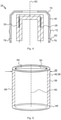
Figure 2 shows an exemplary
atomizer with a heating coil and a wick which is not covered by the invention; -
Figure 3 shows a cross-sectional view on the atomizer/liquid reservoir portion of an electronic smoking device; -
Figure 4 shows a schematic illustration of the atomizer of an electronic smoking device; -
Figure 5 is a schematic illustration of a tube shaped hollow tobacco rod. - Throughout the following, an electronic smoking device will be exemplarily described with reference to an e-cigarette. As is shown in
Figure 1 , ane-cigarette 10 typically has a housing comprising a cylindrical hollow tube having anend cap 16. The cylindrical hollow tube may be a single-piece or a multiple-piece tube. InFigure 1 , the cylindrical hollow tube is shown as a two-piece structure having apower supply portion 12 and an atomizer/liquid reservoir portion 14. Together thepower supply portion 12 and the atomizer/liquid reservoir portion 14 form a cylindrical tube which can be approximately the same size and shape as a conventional cigarette, typically about 100 mm with a 7.5 mm diameter, although lengths may range from 70 to 150 or 180 mm, and diameters from 5 to 28 mm. - The
power supply portion 12 and atomizer/liquid reservoir portion 14 are typically made of metal, e.g. steel or aluminum, or of hardwearing plastic and act together with theend cap 16 to provide a housing to contain the components of thee-cigarette 10. Thepower supply portion 12 and an atomizer/liquid reservoir portion 14 may be configured to fit together by a friction push fit, a snap fit, or a bayonet attachment, magnetic fit, or screw threads. Theend cap 16 is provided at the front end of thepower supply portion 12. Theend cap 16 may be made from translucent plastic or other translucent material to allow a light-emitting diode (LED) 20 positioned near the end cap to emit light through the end cap. The end cap can be made of metal or other materials that do not allow light to pass. - An air inlet may be provided in the end cap, at the edge of the inlet next to the cylindrical hollow tube, anywhere along the length of the cylindrical hollow tube, or at the connection of the
power supply portion 12 and the atomizer/liquid reservoir portion 14.Figure 1 shows a pair ofair inlets 38 provided at the intersection between thepower supply portion 12 and the atomizer/liquid reservoir portion 14. - A
power supply 18, preferably abattery 18, anLED 20,control electronics 22 and optionally anairflow sensor 24 are provided within the cylindrical hollow tubepower supply portion 12. Thebattery 18 is electrically connected to thecontrol electronics 22, which are electrically connected to theLED 20 and theairflow sensor 24. In this example, theLED 20 is at the front end of thepower supply portion 12, adjacent to theend cap 16 and thecontrol electronics 22 andairflow sensor 24 are provided in the central cavity at the other end of thebattery 18 adjacent to the atomizer/liquid reservoir portion 14. - The
airflow sensor 24 acts as a puff detector, detecting a user puffing or sucking on the atomizer/liquid reservoir portion 14 of thee-cigarette 10. Theairflow sensor 24 can be any suitable sensor for detecting changes in airflow or air pressure, such as a microphone switch including a deformable membrane which is caused to move by variations in air pressure. Alternatively, the sensor may be a Hall element or an electro-mechanical sensor. - The
control electronics 22 are also connected to anatomizer 26. In the example shown, theatomizer 26 includes aheating element 28, preferably a heating coil which is wrapped around awick 30 extending across acentral passage 32 of the atomizer/liquid reservoir portion 14. Theheating element 28 may be positioned anywhere in theatomizer 26 and may be transverse or parallel to theliquid reservoir 34. Thewick 30 andheating element 28 do not completely block thecentral passage 32. Rather an air gap is provided on either side of theheating element 28 enabling air to flow past theheating element 28 and thewick 30. Theatomizer 26 may alternatively use other forms ofheating elements 28, such as ceramic heaters, or fiber or mesh material heaters. Nonresistance heating elements such as sonic, piezo and jet spray may also be used in theatomizer 26 in place of the heating coil. - The
central passage 32 is surrounded by acylindrical liquid reservoir 34 with the ends of thewick 30 abutting or extending into theliquid reservoir 34. Thewick 30 may be a porous material such as a bundle of fiberglass fibers, withliquid 44 in theliquid reservoir 34 drawn by capillary action from the ends of thewick 30 towards the central portion of thewick 30 encircled by theheating element 28. Alternatively, thewick 30 may be of porous material such as cotton or contain aporous layer 76. - The
liquid reservoir 34 may alternatively include wadding soaked in liquid which encircles thecentral passage 32 with the ends of thewick 30 abutting the wadding. In other embodiments, theliquid reservoir 34 may comprise a toroidal cavity arranged to be filled withliquid 44 and with the ends of thewick 30 extending into the toroidal cavity. - An
air inhalation port 36 is provided at the back end of the atomizer/liquid reservoir portion 14 remote from theend cap 16. Theinhalation port 36 may be formed from the cylindrical hollow tube atomizer/liquid reservoir portion 14 or maybe formed in an end cap. - In use, a user sucks on the
e-cigarette 10. This causes air to be drawn into thee-cigarette 10 via one or more air inlets, such asair inlets 38, and to be drawn through thecentral passage 32 towards theair inhalation port 36. The change in air pressure which arises is detected by theairflow sensor 24, which generates an electrical signal that is passed to thecontrol electronics 22. In response to the signal, thecontrol electronics 22 activate theheating element 28, which causes liquid present in thewick 30 to be vaporized creating an aerosol (which may comprise gaseous and liquid components) within thecentral passage 32. As the user continues to suck on thee-cigarette 10, this aerosol is drawn through thecentral passage 32 and inhaled by the user. At the same time, thecontrol electronics 22 also activate theLED 20 causing theLED 20 to light up which is visible via thetranslucent end cap 16 mimicking the appearance of a glowing ember at the end of a conventional cigarette. Asliquid 44 present in thewick 30 is converted into an aerosol, more liquid 44 is drawn into thewick 30 from theliquid reservoir 34 by capillary action and thus is available to be converted into an aerosol through subsequent activation of theheating element 28, preferablyheating coil 28. To draw the liquid 44 from theliquid reservoir 34 to thewick 30, the liquid 44 has to penetrate thetobacco element 46, which adds tobacco flavor and nicotine to the liquid, giving the user a more cigarette like taste and allowing to add nicotine to the liquid, even when the liquid itself does not contain any nicotine. - Some e-cigarettes are intended to be disposable and the electric power in the
battery 18 is intended to be sufficient to vaporize the liquid 44 contained within theliquid reservoir 34, after which thee-cigarette 10 is thrown away. In other embodiments thebattery 18 is rechargeable and theliquid reservoir 34 is refillable. In the cases where theliquid reservoir 34 is a toroidal cavity, this may be achieved by refilling theliquid reservoir 34 via a refill port. In other embodiments the atomizer/liquid reservoir portion 14 of the e-cigarette 10 is detachable from thepower supply portion 12 and a new atomizer/liquid reservoir portion 14 can be fitted with anew liquid reservoir 34 thereby replenishing the supply ofliquid 44. In some cases, replacing theliquid reservoir 34 may involve replacement of theheating element 28 and thewick 30 along with the replacement of theliquid reservoir 34. A replaceable unit comprising theatomizer 26 and theliquid reservoir 34 is called a cartomizer. - The
new liquid reservoir 34 may be in the form of a cartridge having acentral passage 32 through which a user inhales aerosol. In other embodiments, aerosol may flow around the exterior of thecartridge 32 to anair inhalation port 36. - Of course, in addition to the above description of the structure and function of a
typical e-cigarette 10, variations also exist. For example, theLED 20 may be omitted. Theairflow sensor 24 may be placed adjacent theend cap 16 rather than in the middle of the e-cigarette. Theairflow sensor 24 may be replaced with a switch which enables a user to activate the e-cigarette manually rather than in response to the detection of a change in air flow or air pressure. - Different types of atomizers may be used. Thus, for example, the atomizer may have a heating coil in a cavity in the interior of a porous body soaked in liquid. In this design aerosol is generated by evaporating the liquid within the porous body either by activation of the coil heating the porous body or alternatively by the heated air passing over or through the porous body. Alternatively, the atomizer may use a piezoelectric atomizer to create an aerosol either in combination or in the absence of a heater. A fluid connection between the
liquid reservoir 34 and theatomizer 26 is formed via aporous tobacco element 46 positioned in between an outlet of theliquid reservoir 34 and thewick 30, such that the liquid 44 has to penetrate thetobacco element 46 to be drawn into thewick 30 and vaporized afterwards. -
Figure 2 shows anexemplary atomizer 26 of an e-cigarette 10 as shown inFigure 1 . - The
atomizer 26 comprises aheating element 28 and awick 30. Theheating element 28 contains preferably a metal heating coil or a ceramic heating element, wherein theheating element 28 is at least partly wrapped around thewick 30. Thewick 30 comprises at least oneporous layer 76 such as a cotton layer or a bundle of fiberglass fibers and atobacco layer 74 that is wrapped around theporous layer 76 of thewick 30. Theheating element 28 is at least partly surrounded by thewick 30. Thetobacco layer 74 encases theporous layer 76 of thewick 30 so that the liquid 44 stored in theliquid reservoir 34 penetrates thetobacco layer 74 before being vaporized by theheating element 28. -
Figure 3 shows a cross-sectional view on the atomizer/liquid reservoir portion 14 of anelectronic smoking device 10. The atomizer/liquid reservoir portion 14 comprises aliquid reservoir 34 and anatomizer 26. Theliquid reservoir 34 is filled with a liquid 44. Theatomizer 26 comprises acoil housing 40 and aheating coil 28, wherein awick 30 is connected to theheating coil 28. Thewick 30 comprises a porous material such ascotton 54 or fiberglass fibers. Thecoil housing 40 has at least oneorifice 78 fluidly connecting theliquid reservoir 34 to thewick 30. Atobacco element 46 in form of a hollow tobacco rod 56 is positioned between theliquid reservoir 34 and thecoil housing 40 of theatomizer 26. Thecoil housing 40 may have achamfer 70 on its front orientated towards theair inhalation port 36 of theelectronic smoking device 10 to simplify a press-fit of the tobacco rod 56 on thecoil housing 40 of theatomizer 26. The tobacco rod 56 is covering theorifices 78 of thecoil housing 40 such that the liquid has to penetrate the tobacco rod 56 to be drawn into thewick 30. While penetrating the tobacco rod 56 the liquid 44 adsorbs the tobacco taste and the nicotine of thetobacco element 46 in order to give the liquid 44 a more cigarette like taste. -
Figure 4 shows anatomizer 26 of anelectronic smoking device 10. Theatomizer 26 comprises ametallic coil housing 40 and aheating coil 28 disposed in thecoil housing 28. Theheating coil 28 is covered by a porous material such as a bundle of fiberglass fibers or cotton. Alternatively, the porous material is at least party surrounded by theheating coil 28. Thecoil housing 40 has two orifices with an offset of 180° to each other, through which the liquid 44 can be drawn into theatomizer 26 and is received in thewick 30, before the liquid 44 is vaporized by theheating coil 28. Theheating coil 28 is connectable to thepower supply portion 12 to heat up the liquid 44 soaked up by thewick 30, when theheating coil 28 is activated and heated up to its operating temperature. -
Figure 5 showstobacco element 46 according to the invention in form of a tube shaped hollow tobacco rod 56. The tobacco rod 56 has aninner diameter 50 adjusted to the diameter of thecoil housing 40 and anouter diameter 48 adjusted to theliquid reservoir 34. The tobacco rod 56 has acentral orifice 64 to receive thecoil housing 40 of theatomizer 26. The tobacco rod 56 may have achamfer 66 to simplify the adjustment of the tobacco rod 56 on thecoil housing 40 of theatomizer 26. Thetobacco element 46 may comprise a retaining element 68 such as a wire or a frame, to keep thetobacco 58 of the tobacco rod 56 in a tube-like shape and prevent parts of thetobacco 58 to fall into the gap between theliquid reservoir 34 and thecoil housing 40. - In summary, in one aspect the
electronic smoking device 10 has apower supply portion 12 comprising apower supply 18 and an atomizer/liquid reservoir portion 14 comprising aliquid reservoir 34 and anatomizer 26 operable when connected to thepower supply 18 to atomize liquid 44 stored in theliquid reservoir 34. The atomizer/liquid reservoir portion 14 further comprises aheating element 28, wherein atobacco element 46 comprisingtobacco 58 is positioned between theliquid reservoir 34 and theheating element 28 of theatomizer 26 such that the liquid 44 stored in theliquid reservoir 34 passes thetobacco element 46 to adsorb the tobacco flavor and nicotine of thetobacco element 46 before being atomized or vaporized by theheating element 28. This allows to transform a single heating electronic smoking device into a hybrid product adding tobacco taste and nicotine to the liquid to give the electronic smoking device a more cigarette like taste. - The
tobacco element 46 is a hollow tobacco rod 56 with acentral orifice 64, wherein thecentral orifice 64 is receivable in theatomizer 26. - This may be in advantage to secure an easy fastening of the
tobacco element 46 on theatomizer 26 to allow the user to exchange thetobacco element 46 in regular intervals for different kind oftobaccos 58 or when thetobacco 58 is losing its taste. - In a further improvement of the
electronic smoking device 10, the hollow tobacco rod 56 has a cylindric shape. A cylindric tobacco rod 56 can be pressed on thecoil housing 40 of theatomizer 26 in any direction, so no orientation of the tobacco rod 56 is needed. - According to the invention, on a front side of the tobacco rod 56 a
chamfer 66 is formed in order to simplify the attachment of the tobacco rod 56 to theatomizer 26. Adding achamfer 66 on the tobacco rod 56 enables the user to have an easy and simplified press-fit of the tobacco element 56 on thecoil housing 40 of theatomizer 26. - According to another embodiment of the
electronic smoking device 10, the tobacco element 56 comprises a retaining element 68, such as a wire or a frame, wherein thetobacco 58 is shaped by the retaining element 68. This may be in advantage to extend the fatigue life of thetobacco element 46 and to avoid that thetobacco 58 crumbles into the gap between theliquid reservoir 34 and thecoil housing 40. - In a preferred embodiment of the
electronic smoking device 10 theheating element 10 comprises a heating coil. A heating coil may support thewick 30 to increase the stability of the wick and improve the atomization or vaporization of the liquid 44. - In another preferred embodiment of the
electronic smoking device 10, theatomizer 26 comprises acoil housing 40, where thetobacco element 46 is connected to thehousing 40 of theatomizer 26. Thecoil housing 40 may have some kind of edge, groove, or stop to simplify the connection of thetobacco element 46 to thecoil housing 40. - Another advantage may be that the
coil housing 40 has astop surface 62 to limit the insertion depth of thetobacco element 46. Therefore it is secured, that thetobacco element 46 is not pressed in to far and covers the fluid path between theliquid reservoir 34 and theheating coil 28 such that thetobacco element 46 has to be penetrated to drawn the liquid 44 to theheating coil 28 of theatomizer 26. - More preferably, the
coil housing 40 of theatomizer 26 has achamfer 70 to simplify the sliding of thetobacco element 46 on thecoil housing 40. Achamfer 70 on the front of thecoil housing 40 orientated towards thetobacco element 46 may avoid thetobacco element 46 for cracking and crumbling when it is pressed on thecoil housing 40 of theatomizer 26. - In addition or alternatively, the
coil housing 40 of theatomizer 26 has a thickening 72, wherein thetobacco element 46 has a press-fit on the thickening 72 of thecoil housing 40. This allows to have an easy press-fitting process, as the tobacco rod 56 is centered by thecoil housing 40 and will be kept in position, when the tobacco rod 56 is pushed over the thickening 72 of thecoil housing 40. This ensures a fastening position of the tobacco rod 56 when it is pressed on thecoil housing 40. - In another preferred embodiment of the
electronic smoking device 10 theatomizer 26 comprises awick 30 and ametal housing 40, wherein thewick 30 is connected to theheating coil 28 and positioned within thehousing 40, wherein thetobacco element 46 is formed as a hollow tobacco rod 56, and wherein the tobacco rod 56 is positioned between theliquid reservoir 34 and thehousing 40 of theatomizer 26. - More preferably, the
housing 40 has anorifice 78 fluidly connecting theliquid reservoir 34 to thewick 30, wherein the tobacco rod 56 is covering theorifice 78, such that a fluid path between theliquid reservoir 34 and thewick 30 is formed via the tobacco rod 56. This ensures that the liquid 44 adsorbs the tobacco taste and the nicotine before being transferred to thewick 30 and vaporized by theheating coil 28. - According to an examplary
electronic smoking device 10, theatomizer 26 comprises awick 30, wherein thewick 30 is at least partly surrounded by theheating coil 28, further comprising ametal housing 40, wherein thetobacco element 46 is placed between thewick 30 and themetal housing 40 of theatomizer 26. In this examplaryelectronic smoking device 10 the atomizer head is manufactured with atobacco wick 30 portion on the inside of the atomizer head wall. This means that the outer material of the atomizer head would be themetal coil housing 40, then there would be a layer oftobacco 74 on the inside of thecoil housing 40, followed by aporous layer 76 such as cotton or fiberglass fibers, and finally having a preferablyvertical heating coil 28 on the inner-most side of theatomizer 26. This means the consumer does not have to buy tobacco rods 56, but rather replaces theatomizer 26 from time to time. Therefore the thickness of thetobacco layer 74 should be adjusted to the thickness of theporous layer 76 to ensure that the tobacco layer lasts 74 as long as the rest of the atomizer head. - More preferably, the wick comprises surrounding tobacco layer, or a tobacco layer is wrapped around a porous layer of the wick. To add the tobacco flavor and the nicotine to the liquid it is preferable that the tobacco layer surrounds the porous layer in order to ensure that the tobacco layer is penetrated by the liquid before the liquid is vaporized or atomized by the heating coil of the atomizer.
- While this invention has been described in connection with what is presently considered to be practical exemplary embodiments, it is to be understood that the invention is not limited to the disclosed embodiments, but the scope of the invention is defined by the appended claims.
-
- 10
- electronic smoking device
- 12
- power supply portion
- 14
- atomizer/liquid reservoir portion
- 16
- end cap
- 18
- power supply / battery
- 20
- light-emitting diode (LED)
- 22
- control electronics
- 24
- airflow sensor
- 26
- atomizer
- 28
- heating element, preferably heating coil
- 30
- wick
- 32
- central passage
- 34
- liquid reservoir
- 36
- air inhalation port
- 38
- air inlets
- 40
- coil housing
- 42
- liquid channel
- 44
- liquid
- 46
- tobacco element
- 48
- outer diameter
- 50
- inner diameter
- 52
- wire
- 54
- cotton
- 56
- tobacco rod
- 58
- tobacco
- 60
- central axis
- 62
- stop surface
- 64
- central orifice
- 66
- chamfer
- 68
- retaining element
- 70
- chamfer
- 72
- thickening
- 74
- tobacco layer
- 76
- porous layer
- 78
- orifice
Claims (11)
- An electronic smoking device (10) comprising:a power supply portion (12) comprising a power supply (18),an atomizer/liquid reservoir portion (14) comprising a liquid reservoir (34), and an atomizer (26) operable when connected to the power supply (18) to atomize liquid (44) stored in the liquid reservoir (34), whereinthe atomizer/liquid reservoir portion (14) further comprises a heating element (28), whereina tobacco element (46) comprising tobacco (58) is positioned between the liquid reservoir (34) and the heating element (28) of the atomizer (26) such that a liquid (44) stored in the liquid reservoir (34) passes the tobacco element (46) to absorb the tobacco flavor of the tobacco element (46) before being vaporized by the heating element (28), wherein the tobacco element (46) is a hollow tobacco rod (56) with a central orifice (64), wherein the central orifice (64) is receivable in the atomizer (26), characterised in that on a front side oriented towards an air inhalation port (36) of the tobacco rod (56) a chamfer (66) is formed in order to simplify the attachment of the tobacco rod (56) to the atomizer (26).
- The electronic smoking device (10) according to claim 1, characterized in that the tobacco element (46) comprises a retaining element (68), wherein the tobacco (58) is shaped by the retaining element (68).
- The electronic smoking device (10) according to claim 1 or 2, characterized in that the heating element (28) comprises a heating coil.
- The electronic smoking device (10) according to claim 3, characterized in that the atomizer (26) comprises a coil housing (40), wherein the tobacco element (46) is connected to the coil housing (40) of the atomizer (26)
- The electronic smoking device (10) according to claim 4, characterized in that the coil housing (40) has a stop surface (62) to limit the insertion depth of the tobacco element (46).
- The electronic smoking device (10) according to claim 4 or claim 5, characterized in that the coil housing (40) of the atomizer (26) has a chamfer (70) to simplify the sliding of the tobacco element (46) on the coil housing (40).
- The electronic smoking device (10) according to any of the claims 4 to 6, characterized in that coil housing (40) of the atomizer (26) has a thickening (72), wherein the tobacco element (46) has a press-fit on the thickening (72) of the coil housing (40).
- The electronic smoking device (10) according to any of the claims 1 to 7, the atomizer (26) further comprising a wick (30) and a metal coil housing (40), wherein the wick (30) is connected to the heating coil (28) and positioned within the coil housing (40), wherein the tobacco element (46) is formed as a hollow tobacco rod (56), and wherein the tobacco rod (56) is positioned between the liquid reservoir (34) and the coil housing (40) of the atomizer (26).
- The electronic smoking device (10) according to claim 8, wherein the coil housing (40) has an orifice (78) fluidly connecting the liquid reservoir (34) to the wick (30), wherein the tobacco rod (56) is covering the orifice (78), such that a fluid path between the liquid reservoir (34) and the wick is formed via the tobacco rod (56).
- A method of assembling an electronic smoking device (10) according to any of the claims 1 to 9, wherein a tobacco element (46) is inserted into a central passage (32) of the electronic smoking device (10) and connected to the atomizer (26), wherein the tobacco element (46) is fluidly connected to the liquid reservoir (34) such that a liquid (44) is transported to the atomizer via the tobacco element (46).
- An atomizer/liquid reservoir portion (14) comprising:a liquid reservoir (34), andan atomizer (26) operable when connected to a power supply (18) for an electronic smoking device (10) to atomize liquid stored in the liquid reservoir (34),whereinthe atomizer/liquid reservoir portion (14) further comprises a heating element (28) and a tobacco element (46), wherein the tobacco element (46) is positioned between the liquid reservoir (34) and the heating element (28) of the atomizer (26) such that a liquid (44) stored in the liquid reservoir (34) passes the tobacco element (46) to adsorb the tobacco flavour of the tobacco element (46) before being vaporized by the heating element (28), wherein the tobacco element (46) is a hollow tobacco rod (56) with a central orifice (64), wherein the central orifice (64) is receivable in the atomizer (26), wherein on a front side oriented towards an air inhalation port (36) of the tobacco rod (56) a chamfer (66) is formed in order to simplify the attachment of the tobacco rod (56) to the atomizer (26)..
Priority Applications (3)
| Application Number | Priority Date | Filing Date | Title |
|---|---|---|---|
| EP18207134.0A EP3656228B1 (en) | 2018-11-20 | 2018-11-20 | Electronic smoking device |
| PCT/EP2019/081789 WO2020104451A1 (en) | 2018-11-20 | 2019-11-19 | Electronic smoking device |
| US17/294,669 US20210401040A1 (en) | 2018-11-20 | 2019-11-19 | Electronic smoking device |
Applications Claiming Priority (1)
| Application Number | Priority Date | Filing Date | Title |
|---|---|---|---|
| EP18207134.0A EP3656228B1 (en) | 2018-11-20 | 2018-11-20 | Electronic smoking device |
Publications (2)
| Publication Number | Publication Date |
|---|---|
| EP3656228A1 EP3656228A1 (en) | 2020-05-27 |
| EP3656228B1 true EP3656228B1 (en) | 2022-03-16 |
Family
ID=64402017
Family Applications (1)
| Application Number | Title | Priority Date | Filing Date |
|---|---|---|---|
| EP18207134.0A Active EP3656228B1 (en) | 2018-11-20 | 2018-11-20 | Electronic smoking device |
Country Status (3)
| Country | Link |
|---|---|
| US (1) | US20210401040A1 (en) |
| EP (1) | EP3656228B1 (en) |
| WO (1) | WO2020104451A1 (en) |
Family Cites Families (4)
| Publication number | Priority date | Publication date | Assignee | Title |
|---|---|---|---|---|
| US20160374393A1 (en) * | 2013-11-28 | 2016-12-29 | Hk Triangle Co., Limited | Electronic cigarette atomizer |
| CN108348709B (en) * | 2015-11-30 | 2021-04-20 | 菲利普莫里斯生产公司 | Non-combustible smoking device and components thereof |
| CN110113959B (en) * | 2016-12-27 | 2021-11-23 | 日本烟草产业株式会社 | Heating type fragrance suction device |
| US10792443B2 (en) * | 2017-06-30 | 2020-10-06 | Blackship Technologies Development Llc | Composite micro-vaporizer wicks |
-
2018
- 2018-11-20 EP EP18207134.0A patent/EP3656228B1/en active Active
-
2019
- 2019-11-19 WO PCT/EP2019/081789 patent/WO2020104451A1/en active Application Filing
- 2019-11-19 US US17/294,669 patent/US20210401040A1/en active Pending
Also Published As
| Publication number | Publication date |
|---|---|
| EP3656228A1 (en) | 2020-05-27 |
| WO2020104451A1 (en) | 2020-05-28 |
| US20210401040A1 (en) | 2021-12-30 |
Similar Documents
| Publication | Publication Date | Title |
|---|---|---|
| US10729174B2 (en) | Electronic smoking device with liquid reservoir including an actuator | |
| US11956862B2 (en) | Electronic cigarette wick | |
| CN108135258B (en) | Electronic smoking device with capillary buffer | |
| CN108289503B (en) | Sliding attachment for electronic smoking device | |
| EP3135136B1 (en) | Liquid reservoir with two storage volumes and atomizer/liquid reservoir portion as well as electronic smoking device with liquid reservoir | |
| EP3135138B1 (en) | Electronic smoking device | |
| US20180132523A1 (en) | Electronic smoking device | |
| EP3042579A1 (en) | Electronic smoking device | |
| EP3536177B1 (en) | Electronic smoking device with liquid pump | |
| EP3656228B1 (en) | Electronic smoking device |
Legal Events
| Date | Code | Title | Description |
|---|---|---|---|
| PUAI | Public reference made under article 153(3) epc to a published international application that has entered the european phase |
Free format text: ORIGINAL CODE: 0009012 |
|
| STAA | Information on the status of an ep patent application or granted ep patent |
Free format text: STATUS: THE APPLICATION HAS BEEN PUBLISHED |
|
| AK | Designated contracting states |
Kind code of ref document: A1 Designated state(s): AL AT BE BG CH CY CZ DE DK EE ES FI FR GB GR HR HU IE IS IT LI LT LU LV MC MK MT NL NO PL PT RO RS SE SI SK SM TR |
|
| AX | Request for extension of the european patent |
Extension state: BA ME |
|
| STAA | Information on the status of an ep patent application or granted ep patent |
Free format text: STATUS: REQUEST FOR EXAMINATION WAS MADE |
|
| 17P | Request for examination filed |
Effective date: 20201124 |
|
| RBV | Designated contracting states (corrected) |
Designated state(s): AL AT BE BG CH CY CZ DE DK EE ES FI FR GB GR HR HU IE IS IT LI LT LU LV MC MK MT NL NO PL PT RO RS SE SI SK SM TR |
|
| REG | Reference to a national code |
Ref country code: DE Ref legal event code: R079 Ref document number: 602018032255 Country of ref document: DE Free format text: PREVIOUS MAIN CLASS: A24F0047000000 Ipc: A24F0040440000 |
|
| GRAP | Despatch of communication of intention to grant a patent |
Free format text: ORIGINAL CODE: EPIDOSNIGR1 |
|
| STAA | Information on the status of an ep patent application or granted ep patent |
Free format text: STATUS: GRANT OF PATENT IS INTENDED |
|
| RIC1 | Information provided on ipc code assigned before grant |
Ipc: A24F 40/30 20200101ALN20211104BHEP Ipc: A24F 40/10 20200101ALN20211104BHEP Ipc: A24F 40/44 20200101AFI20211104BHEP |
|
| RIC1 | Information provided on ipc code assigned before grant |
Ipc: A24F 40/30 20200101ALN20211110BHEP Ipc: A24F 40/10 20200101ALN20211110BHEP Ipc: A24F 40/44 20200101AFI20211110BHEP |
|
| INTG | Intention to grant announced |
Effective date: 20211129 |
|
| GRAS | Grant fee paid |
Free format text: ORIGINAL CODE: EPIDOSNIGR3 |
|
| GRAA | (expected) grant |
Free format text: ORIGINAL CODE: 0009210 |
|
| STAA | Information on the status of an ep patent application or granted ep patent |
Free format text: STATUS: THE PATENT HAS BEEN GRANTED |
|
| AK | Designated contracting states |
Kind code of ref document: B1 Designated state(s): AL AT BE BG CH CY CZ DE DK EE ES FI FR GB GR HR HU IE IS IT LI LT LU LV MC MK MT NL NO PL PT RO RS SE SI SK SM TR |
|
| REG | Reference to a national code |
Ref country code: GB Ref legal event code: FG4D |
|
| REG | Reference to a national code |
Ref country code: CH Ref legal event code: EP |
|
| REG | Reference to a national code |
Ref country code: DE Ref legal event code: R096 Ref document number: 602018032255 Country of ref document: DE |
|
| REG | Reference to a national code |
Ref country code: IE Ref legal event code: FG4D |
|
| REG | Reference to a national code |
Ref country code: AT Ref legal event code: REF Ref document number: 1475265 Country of ref document: AT Kind code of ref document: T Effective date: 20220415 |
|
| REG | Reference to a national code |
Ref country code: LT Ref legal event code: MG9D |
|
| REG | Reference to a national code |
Ref country code: NL Ref legal event code: MP Effective date: 20220316 |
|
| PG25 | Lapsed in a contracting state [announced via postgrant information from national office to epo] |
Ref country code: SE Free format text: LAPSE BECAUSE OF FAILURE TO SUBMIT A TRANSLATION OF THE DESCRIPTION OR TO PAY THE FEE WITHIN THE PRESCRIBED TIME-LIMIT Effective date: 20220316 Ref country code: RS Free format text: LAPSE BECAUSE OF FAILURE TO SUBMIT A TRANSLATION OF THE DESCRIPTION OR TO PAY THE FEE WITHIN THE PRESCRIBED TIME-LIMIT Effective date: 20220316 Ref country code: NO Free format text: LAPSE BECAUSE OF FAILURE TO SUBMIT A TRANSLATION OF THE DESCRIPTION OR TO PAY THE FEE WITHIN THE PRESCRIBED TIME-LIMIT Effective date: 20220616 Ref country code: LT Free format text: LAPSE BECAUSE OF FAILURE TO SUBMIT A TRANSLATION OF THE DESCRIPTION OR TO PAY THE FEE WITHIN THE PRESCRIBED TIME-LIMIT Effective date: 20220316 Ref country code: HR Free format text: LAPSE BECAUSE OF FAILURE TO SUBMIT A TRANSLATION OF THE DESCRIPTION OR TO PAY THE FEE WITHIN THE PRESCRIBED TIME-LIMIT Effective date: 20220316 Ref country code: BG Free format text: LAPSE BECAUSE OF FAILURE TO SUBMIT A TRANSLATION OF THE DESCRIPTION OR TO PAY THE FEE WITHIN THE PRESCRIBED TIME-LIMIT Effective date: 20220616 |
|
| REG | Reference to a national code |
Ref country code: AT Ref legal event code: MK05 Ref document number: 1475265 Country of ref document: AT Kind code of ref document: T Effective date: 20220316 |
|
| PG25 | Lapsed in a contracting state [announced via postgrant information from national office to epo] |
Ref country code: LV Free format text: LAPSE BECAUSE OF FAILURE TO SUBMIT A TRANSLATION OF THE DESCRIPTION OR TO PAY THE FEE WITHIN THE PRESCRIBED TIME-LIMIT Effective date: 20220316 Ref country code: GR Free format text: LAPSE BECAUSE OF FAILURE TO SUBMIT A TRANSLATION OF THE DESCRIPTION OR TO PAY THE FEE WITHIN THE PRESCRIBED TIME-LIMIT Effective date: 20220617 Ref country code: FI Free format text: LAPSE BECAUSE OF FAILURE TO SUBMIT A TRANSLATION OF THE DESCRIPTION OR TO PAY THE FEE WITHIN THE PRESCRIBED TIME-LIMIT Effective date: 20220316 |
|
| PG25 | Lapsed in a contracting state [announced via postgrant information from national office to epo] |
Ref country code: NL Free format text: LAPSE BECAUSE OF FAILURE TO SUBMIT A TRANSLATION OF THE DESCRIPTION OR TO PAY THE FEE WITHIN THE PRESCRIBED TIME-LIMIT Effective date: 20220316 |
|
| PG25 | Lapsed in a contracting state [announced via postgrant information from national office to epo] |
Ref country code: SM Free format text: LAPSE BECAUSE OF FAILURE TO SUBMIT A TRANSLATION OF THE DESCRIPTION OR TO PAY THE FEE WITHIN THE PRESCRIBED TIME-LIMIT Effective date: 20220316 Ref country code: SK Free format text: LAPSE BECAUSE OF FAILURE TO SUBMIT A TRANSLATION OF THE DESCRIPTION OR TO PAY THE FEE WITHIN THE PRESCRIBED TIME-LIMIT Effective date: 20220316 Ref country code: RO Free format text: LAPSE BECAUSE OF FAILURE TO SUBMIT A TRANSLATION OF THE DESCRIPTION OR TO PAY THE FEE WITHIN THE PRESCRIBED TIME-LIMIT Effective date: 20220316 Ref country code: PT Free format text: LAPSE BECAUSE OF FAILURE TO SUBMIT A TRANSLATION OF THE DESCRIPTION OR TO PAY THE FEE WITHIN THE PRESCRIBED TIME-LIMIT Effective date: 20220718 Ref country code: ES Free format text: LAPSE BECAUSE OF FAILURE TO SUBMIT A TRANSLATION OF THE DESCRIPTION OR TO PAY THE FEE WITHIN THE PRESCRIBED TIME-LIMIT Effective date: 20220316 Ref country code: EE Free format text: LAPSE BECAUSE OF FAILURE TO SUBMIT A TRANSLATION OF THE DESCRIPTION OR TO PAY THE FEE WITHIN THE PRESCRIBED TIME-LIMIT Effective date: 20220316 Ref country code: CZ Free format text: LAPSE BECAUSE OF FAILURE TO SUBMIT A TRANSLATION OF THE DESCRIPTION OR TO PAY THE FEE WITHIN THE PRESCRIBED TIME-LIMIT Effective date: 20220316 Ref country code: AT Free format text: LAPSE BECAUSE OF FAILURE TO SUBMIT A TRANSLATION OF THE DESCRIPTION OR TO PAY THE FEE WITHIN THE PRESCRIBED TIME-LIMIT Effective date: 20220316 |
|
| PG25 | Lapsed in a contracting state [announced via postgrant information from national office to epo] |
Ref country code: PL Free format text: LAPSE BECAUSE OF FAILURE TO SUBMIT A TRANSLATION OF THE DESCRIPTION OR TO PAY THE FEE WITHIN THE PRESCRIBED TIME-LIMIT Effective date: 20220316 Ref country code: IS Free format text: LAPSE BECAUSE OF FAILURE TO SUBMIT A TRANSLATION OF THE DESCRIPTION OR TO PAY THE FEE WITHIN THE PRESCRIBED TIME-LIMIT Effective date: 20220716 Ref country code: AL Free format text: LAPSE BECAUSE OF FAILURE TO SUBMIT A TRANSLATION OF THE DESCRIPTION OR TO PAY THE FEE WITHIN THE PRESCRIBED TIME-LIMIT Effective date: 20220316 |
|
| REG | Reference to a national code |
Ref country code: DE Ref legal event code: R097 Ref document number: 602018032255 Country of ref document: DE |
|
| PGFP | Annual fee paid to national office [announced via postgrant information from national office to epo] |
Ref country code: FR Payment date: 20221021 Year of fee payment: 5 |
|
| PLBE | No opposition filed within time limit |
Free format text: ORIGINAL CODE: 0009261 |
|
| STAA | Information on the status of an ep patent application or granted ep patent |
Free format text: STATUS: NO OPPOSITION FILED WITHIN TIME LIMIT |
|
| PG25 | Lapsed in a contracting state [announced via postgrant information from national office to epo] |
Ref country code: DK Free format text: LAPSE BECAUSE OF FAILURE TO SUBMIT A TRANSLATION OF THE DESCRIPTION OR TO PAY THE FEE WITHIN THE PRESCRIBED TIME-LIMIT Effective date: 20220316 |
|
| PGFP | Annual fee paid to national office [announced via postgrant information from national office to epo] |
Ref country code: GB Payment date: 20221021 Year of fee payment: 5 Ref country code: DE Payment date: 20221020 Year of fee payment: 5 |
|
| 26N | No opposition filed |
Effective date: 20221219 |
|
| PG25 | Lapsed in a contracting state [announced via postgrant information from national office to epo] |
Ref country code: SI Free format text: LAPSE BECAUSE OF FAILURE TO SUBMIT A TRANSLATION OF THE DESCRIPTION OR TO PAY THE FEE WITHIN THE PRESCRIBED TIME-LIMIT Effective date: 20220316 |
|
| PG25 | Lapsed in a contracting state [announced via postgrant information from national office to epo] |
Ref country code: MC Free format text: LAPSE BECAUSE OF FAILURE TO SUBMIT A TRANSLATION OF THE DESCRIPTION OR TO PAY THE FEE WITHIN THE PRESCRIBED TIME-LIMIT Effective date: 20220316 |
|
| REG | Reference to a national code |
Ref country code: CH Ref legal event code: PL |
|
| REG | Reference to a national code |
Ref country code: BE Ref legal event code: MM Effective date: 20221130 |
|
| PG25 | Lapsed in a contracting state [announced via postgrant information from national office to epo] |
Ref country code: LI Free format text: LAPSE BECAUSE OF NON-PAYMENT OF DUE FEES Effective date: 20221130 Ref country code: IT Free format text: LAPSE BECAUSE OF FAILURE TO SUBMIT A TRANSLATION OF THE DESCRIPTION OR TO PAY THE FEE WITHIN THE PRESCRIBED TIME-LIMIT Effective date: 20220316 Ref country code: CH Free format text: LAPSE BECAUSE OF NON-PAYMENT OF DUE FEES Effective date: 20221130 |
|
| PG25 | Lapsed in a contracting state [announced via postgrant information from national office to epo] |
Ref country code: LU Free format text: LAPSE BECAUSE OF NON-PAYMENT OF DUE FEES Effective date: 20221120 |
|
| PG25 | Lapsed in a contracting state [announced via postgrant information from national office to epo] |
Ref country code: IE Free format text: LAPSE BECAUSE OF NON-PAYMENT OF DUE FEES Effective date: 20221120 |
|
| PG25 | Lapsed in a contracting state [announced via postgrant information from national office to epo] |
Ref country code: BE Free format text: LAPSE BECAUSE OF NON-PAYMENT OF DUE FEES Effective date: 20221130 |
|
| PG25 | Lapsed in a contracting state [announced via postgrant information from national office to epo] |
Ref country code: HU Free format text: LAPSE BECAUSE OF FAILURE TO SUBMIT A TRANSLATION OF THE DESCRIPTION OR TO PAY THE FEE WITHIN THE PRESCRIBED TIME-LIMIT; INVALID AB INITIO Effective date: 20181120 |