EP3655917B1 - Fetal ultrasound image processing - Google Patents
Fetal ultrasound image processing Download PDFInfo
- Publication number
- EP3655917B1 EP3655917B1 EP18743435.2A EP18743435A EP3655917B1 EP 3655917 B1 EP3655917 B1 EP 3655917B1 EP 18743435 A EP18743435 A EP 18743435A EP 3655917 B1 EP3655917 B1 EP 3655917B1
- Authority
- EP
- European Patent Office
- Prior art keywords
- ultrasound image
- fetal ultrasound
- image
- spine
- fetal
- Prior art date
- Legal status (The legal status is an assumption and is not a legal conclusion. Google has not performed a legal analysis and makes no representation as to the accuracy of the status listed.)
- Active
Links
- 238000002604 ultrasonography Methods 0.000 title claims description 107
- 230000001605 fetal effect Effects 0.000 title claims description 79
- 238000012545 processing Methods 0.000 title claims description 20
- 238000000034 method Methods 0.000 claims description 72
- 238000012549 training Methods 0.000 claims description 40
- 210000003754 fetus Anatomy 0.000 claims description 30
- 239000013598 vector Substances 0.000 claims description 24
- 238000010801 machine learning Methods 0.000 claims description 22
- 238000004422 calculation algorithm Methods 0.000 claims description 16
- 238000010606 normalization Methods 0.000 claims description 13
- 210000001015 abdomen Anatomy 0.000 claims description 11
- 238000013135 deep learning Methods 0.000 claims description 10
- 239000000523 sample Substances 0.000 claims description 10
- 230000004044 response Effects 0.000 claims description 9
- 230000000877 morphologic effect Effects 0.000 claims description 8
- 230000035935 pregnancy Effects 0.000 claims description 6
- 210000000038 chest Anatomy 0.000 claims description 5
- 238000004590 computer program Methods 0.000 claims description 4
- 238000005070 sampling Methods 0.000 claims description 2
- 238000013459 approach Methods 0.000 description 13
- 238000001514 detection method Methods 0.000 description 13
- 210000000056 organ Anatomy 0.000 description 12
- 230000005540 biological transmission Effects 0.000 description 11
- 238000003384 imaging method Methods 0.000 description 11
- 230000008569 process Effects 0.000 description 10
- 230000006870 function Effects 0.000 description 9
- 210000003371 toe Anatomy 0.000 description 8
- 238000000605 extraction Methods 0.000 description 6
- 238000005259 measurement Methods 0.000 description 6
- 230000033001 locomotion Effects 0.000 description 5
- 238000012360 testing method Methods 0.000 description 5
- 210000001519 tissue Anatomy 0.000 description 5
- 230000003187 abdominal effect Effects 0.000 description 4
- 230000017531 blood circulation Effects 0.000 description 4
- 238000010191 image analysis Methods 0.000 description 4
- 210000003734 kidney Anatomy 0.000 description 4
- 238000011002 quantification Methods 0.000 description 4
- 210000002784 stomach Anatomy 0.000 description 4
- 230000008901 benefit Effects 0.000 description 3
- 210000004027 cell Anatomy 0.000 description 3
- 238000002059 diagnostic imaging Methods 0.000 description 3
- 238000003780 insertion Methods 0.000 description 3
- 230000037431 insertion Effects 0.000 description 3
- 238000007637 random forest analysis Methods 0.000 description 3
- 238000000926 separation method Methods 0.000 description 3
- 210000003484 anatomy Anatomy 0.000 description 2
- 238000002592 echocardiography Methods 0.000 description 2
- 238000001914 filtration Methods 0.000 description 2
- 238000013507 mapping Methods 0.000 description 2
- 239000000463 material Substances 0.000 description 2
- 239000002033 PVDF binder Substances 0.000 description 1
- 230000005856 abnormality Effects 0.000 description 1
- 238000013528 artificial neural network Methods 0.000 description 1
- 230000029777 axis specification Effects 0.000 description 1
- 210000000601 blood cell Anatomy 0.000 description 1
- 210000000988 bone and bone Anatomy 0.000 description 1
- 230000003139 buffering effect Effects 0.000 description 1
- 210000001217 buttock Anatomy 0.000 description 1
- 239000003086 colorant Substances 0.000 description 1
- 238000013329 compounding Methods 0.000 description 1
- 238000013527 convolutional neural network Methods 0.000 description 1
- 230000001419 dependent effect Effects 0.000 description 1
- 238000003745 diagnosis Methods 0.000 description 1
- 230000000694 effects Effects 0.000 description 1
- 230000008030 elimination Effects 0.000 description 1
- 238000003379 elimination reaction Methods 0.000 description 1
- 210000003414 extremity Anatomy 0.000 description 1
- 210000002414 leg Anatomy 0.000 description 1
- 230000004807 localization Effects 0.000 description 1
- 238000012544 monitoring process Methods 0.000 description 1
- 238000003909 pattern recognition Methods 0.000 description 1
- 229920002981 polyvinylidene fluoride Polymers 0.000 description 1
- 230000000644 propagated effect Effects 0.000 description 1
- 230000000306 recurrent effect Effects 0.000 description 1
- 230000009467 reduction Effects 0.000 description 1
- 230000011218 segmentation Effects 0.000 description 1
- 239000000126 substance Substances 0.000 description 1
- 210000003606 umbilical vein Anatomy 0.000 description 1
- 210000000689 upper leg Anatomy 0.000 description 1
Images


Classifications
-
- G—PHYSICS
- G06—COMPUTING; CALCULATING OR COUNTING
- G06T—IMAGE DATA PROCESSING OR GENERATION, IN GENERAL
- G06T7/00—Image analysis
- G06T7/0002—Inspection of images, e.g. flaw detection
- G06T7/0012—Biomedical image inspection
-
- A—HUMAN NECESSITIES
- A61—MEDICAL OR VETERINARY SCIENCE; HYGIENE
- A61B—DIAGNOSIS; SURGERY; IDENTIFICATION
- A61B8/00—Diagnosis using ultrasonic, sonic or infrasonic waves
- A61B8/08—Detecting organic movements or changes, e.g. tumours, cysts, swellings
- A61B8/0866—Detecting organic movements or changes, e.g. tumours, cysts, swellings involving foetal diagnosis; pre-natal or peri-natal diagnosis of the baby
-
- A—HUMAN NECESSITIES
- A61—MEDICAL OR VETERINARY SCIENCE; HYGIENE
- A61B—DIAGNOSIS; SURGERY; IDENTIFICATION
- A61B8/00—Diagnosis using ultrasonic, sonic or infrasonic waves
- A61B8/48—Diagnostic techniques
- A61B8/483—Diagnostic techniques involving the acquisition of a 3D volume of data
-
- A—HUMAN NECESSITIES
- A61—MEDICAL OR VETERINARY SCIENCE; HYGIENE
- A61B—DIAGNOSIS; SURGERY; IDENTIFICATION
- A61B8/00—Diagnosis using ultrasonic, sonic or infrasonic waves
- A61B8/52—Devices using data or image processing specially adapted for diagnosis using ultrasonic, sonic or infrasonic waves
- A61B8/5215—Devices using data or image processing specially adapted for diagnosis using ultrasonic, sonic or infrasonic waves involving processing of medical diagnostic data
- A61B8/5223—Devices using data or image processing specially adapted for diagnosis using ultrasonic, sonic or infrasonic waves involving processing of medical diagnostic data for extracting a diagnostic or physiological parameter from medical diagnostic data
-
- G06T3/18—
-
- G06T5/60—
-
- G06T5/80—
-
- G—PHYSICS
- G06—COMPUTING; CALCULATING OR COUNTING
- G06T—IMAGE DATA PROCESSING OR GENERATION, IN GENERAL
- G06T7/00—Image analysis
- G06T7/70—Determining position or orientation of objects or cameras
- G06T7/73—Determining position or orientation of objects or cameras using feature-based methods
-
- G—PHYSICS
- G06—COMPUTING; CALCULATING OR COUNTING
- G06T—IMAGE DATA PROCESSING OR GENERATION, IN GENERAL
- G06T2207/00—Indexing scheme for image analysis or image enhancement
- G06T2207/10—Image acquisition modality
- G06T2207/10132—Ultrasound image
- G06T2207/10136—3D ultrasound image
-
- G—PHYSICS
- G06—COMPUTING; CALCULATING OR COUNTING
- G06T—IMAGE DATA PROCESSING OR GENERATION, IN GENERAL
- G06T2207/00—Indexing scheme for image analysis or image enhancement
- G06T2207/20—Special algorithmic details
- G06T2207/20081—Training; Learning
-
- G—PHYSICS
- G06—COMPUTING; CALCULATING OR COUNTING
- G06T—IMAGE DATA PROCESSING OR GENERATION, IN GENERAL
- G06T2207/00—Indexing scheme for image analysis or image enhancement
- G06T2207/20—Special algorithmic details
- G06T2207/20084—Artificial neural networks [ANN]
-
- G—PHYSICS
- G06—COMPUTING; CALCULATING OR COUNTING
- G06T—IMAGE DATA PROCESSING OR GENERATION, IN GENERAL
- G06T2207/00—Indexing scheme for image analysis or image enhancement
- G06T2207/30—Subject of image; Context of image processing
- G06T2207/30004—Biomedical image processing
- G06T2207/30008—Bone
- G06T2207/30012—Spine; Backbone
-
- G—PHYSICS
- G06—COMPUTING; CALCULATING OR COUNTING
- G06T—IMAGE DATA PROCESSING OR GENERATION, IN GENERAL
- G06T2207/00—Indexing scheme for image analysis or image enhancement
- G06T2207/30—Subject of image; Context of image processing
- G06T2207/30004—Biomedical image processing
- G06T2207/30044—Fetus; Embryo
Definitions
- This invention relates to the processing of fetal ultrasound images.
- 2D ultrasound is the preferred scanning protocol for biometry measurements, growth monitoring and anatomy assessment during pregnancy.
- Obtaining reproducible and accurate values requires strict guidelines to be followed, especially regarding the selection of the standard 2D viewing planes which are used to search for abnormalities or perform biometry measurements such as head and abdomen circumference or femur length.
- This task can be very difficult because of multiple factors, such as the mother morphology, the unknown and highly variable orientation of the fetus as well as well-known US artefacts, in particular the shadowing effect.
- 3D US is a more recent imaging technique that has the potential to overcome some of the above mentioned difficulties.
- the acquisition of a single 3D volume makes it possible to select the required viewing planes.
- the clinicians can perform offline reading and, if necessary, adjust the position of the extracted planes (called "clinical planes") prior to standard measurements.
- Views of interest can be selected from 2D US sequences by classifying the content of each frame to determine if it corresponds to a standard plane using a radial component model or a pre-trained recurrent neural network.
- Document US 2010/099987 A1 describes an ultrasonic image acquisition and diagnosis display technique in which the spine of a fetus included in a 3D volume scan is used as a landmark for recognizing the position of the heart in the chest of the fetus with high accuracy.
- Another 2D approach consists in fitting geometrical templates built at multiple resolutions and orientations in order to label the anatomical content.
- a first reference axis is based on the spine, and it may be the direction of the spine in the middle of the spine, or it may be the direction of the vector connecting identified end points of the spine, for example.
- the spine is a well-defined, unique structure within the fetus that will be readily recognizable to the ultrasound system, particularly when using image recognition techniques.
- the second reference axis enables volume rotation about the spine (i.e. about the first reference axis), so that a 3D orientation of the fetus is identified.
- the updated image may be a rotated version of the image, or it may be the image with additional data annotations identifying the reference axes.
- the method may be implemented in real time, so that the 3D ultrasound image is obtained by an ultrasound scan as part of the method. Alternatively, the method may be applied to a previously captured image.
- identification of landmark points (such as organs) within the image is made possible by an automated machine learning approach.
- the method may for example be used to process samples of a training database to provide a machine learning operation, and then the machine learned algorithm may be used to process an unseen captured image (i.e. one not included already processed to create the training database) to provide automated identification.
- the invention may be considered to provide an image filtering or normalization process which can be applied before applying machine learning approaches in order to perform automatic extraction of the clinical planes of interest.
- the determining of the second reference axis comprises:
- the spine is at one edge of the abdomen/thorax, so the vector between the spine and the center of the ellipse (or circle) represents a rotational orientation.
- the vector between the spine and the center of the ellipse (or circle) represents a rotational orientation.
- the torso/abdomen is the largest portion of the fetus, it is easily measurable, thereby increasing the accuracy of the alignment.
- the elliptical or circular form is for example obtained by performing a Hankel transform on the plane.
- the generating of the second reference axis may comprise:
- a second reference axis is obtained which is reliably consistent between different images.
- Taking an average may comprise calculating a weighted average, with greater weighting in the middle of the spine than at the ends of the spine.
- the method may further comprise:
- the updating may again comprise an image manipulation or annotation of the image with an up/down indication.
- the method may further comprise:
- the scale variability between 3D fetal ultrasound images due to gestation age is reduced, and/or the intensity variation due to varying image acquisition gains and imaging conditions may be reduced.
- the scaling and intensity normalization may take place before or after the reference axis determination and re-orientation.
- the detecting of the spine within the 3D fetal ultrasound image for example comprises:
- the spine mask is preferably a binary mask.
- the detection of the spine takes advantages of the strengths of both methods, so that the position of the spine within the 3D fetal ultrasound image can be more robustly determined.
- the invention also provides a method of generating a training database based on 3D fetal ultrasound images and generating an algorithm, comprising:
- the landmark identifications in the received training set are for example manually provided by a clinician. These provide the information for a machine learning algorithm to be able to identify the landmarks in a new image.
- the landmarks are for example organs, such as the heart, bladder, kidneys and umbilical insertion.
- the method may comprise determining the head/toe orientation of the fetus by:
- the patch size is for example based on a fetal gestation age and a resolution of the 3D fetal ultrasound image.
- the invention also provides a method of identifying landmarks within a 3D fetal ultrasound image, comprising:
- This method provides identification of landmarks using the previous machine learning from the testing database, so that the landmarks may be located in an automated way.
- the 3D orientation processing removes or reduces uncertainties resulting from unknown fetal positions.
- the identified landmarks may then be used to control the generation of 2D image planes of interest, namely planes which pass through organs or other landmarks of interest, or are defined with respect to the position of such organs or other landmarks.
- the training database used in this method is generated using the method as defined above.
- the invention also provides a computer program and a controller for controlling the processing a 3D fetal ultrasound image, wherein the controller comprises instructions thereon that when executed cause the controller to implement the methods defined above.
- the invention also provides an ultrasound system, the system comprising:
- the invention provides a computer implemented method for processing a 3D fetal ultrasound image.
- a 3D fetal ultrasound image is obtained (either acquired or received from memory), and the spine is detected within the image.
- This enables a first reference axis to be defined.
- a second reference axis is defined perpendicular to the first reference axis, and the 3D fetal ultrasound image is updated (e.g. rotated in 3D space) using the first and second reference axes and an up/down (elevation) orientation detection.
- This provides a normalization of the orientation of the image, so that a machine learning approach is better able to identify landmarks within new images.
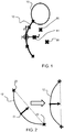
- Figure 1 shows a representation of a fetus comprising a head 10 and spine 12.
- the fetus is positioned within 3D space as defined by the axes x,y,z and with an origin at the center of the spine.
- planes are selected to pass through landmarks of interest. These landmarks are typically organs or other anatomical features such as the stomach 14, heart 16 or umbilical insertion 18.
- This invention relates to an alignment procedure by which an image is aligned in a consistent way in 3D space before further image analysis.
- the further image analysis may be for locating the landmarks so that desired imaging planes may be automatically generated, or it may be for populating a training database.
- the method of the invention may be used for individual image analysis and/or for image analysis to populate a training database.
- the first step in the method is to detect the spine and derive a first reference (orientation) axis.
- the spine may be automatically detected in a 3D ultrasound image by combining a morphological filter which detects elongated bright structures and a deep learning (DL) based vertebrae detector, in order to take advantage of the strengths of both methods.
- a morphological filter which detects elongated bright structures
- a deep learning (DL) based vertebrae detector in order to take advantage of the strengths of both methods.
- a morphological filter may be used. For each voxel x in the US volume in a given spherical neighborhood, to compare the intensity of the voxels along a direction u with the intensity of the other voxels.
- the filter responses are computed for various neighborhood radii and orientations u and combined to obtain a global response.
- the global responses of neighboring voxels are aggregated to define connected components which correspond to the best filter responses.
- the deep learning-based vertebrae detector is a 2D fully convolutional network whose input is made of 2D slices, extracted orthogonally to the original identified z-axis.
- the volume slicing produces a large amount of data with similar features, which is appropriate for deep learning methods.
- the network output is a down sampled probability map, with values closer to 1 where the spine might be located.
- a 3D deep learning-based vertebrae detector is formed by stacking all the obtained 2D probability maps for one volume. This output heatmap is coarser than the morphological filter output, but more robustly located around the vertebrae.
- the network output is refined and the filter responses that are outside the spine are rejected, so that a robust spine binary mask is finally obtained.
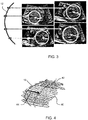
- Figure 2 shows on the left a randomly oriented spine 12.
- the spine detection basically involves identifying the spine, and using the center of mass of the spine binary mask to define the origin O of a reference coordinate system. If the detected spine is highly curved, its center of mass might not belong to the binary mask. This is because the so-called barycenter of the spine can be outside the spine itself and hence not aligned with the mask. In this case, the binary mask point that is the closest to the center of mass is used. Then the extremities 20 of the spine binary mask are used to define the vertical z axis. Alternatively a normal direction tangential to the central point of the spine may be used. The resulting z axis is shown in Figure 1 .
- the image can be updated to include the z axis information, for example by rotating the image to position the z-axis in the defined (e.g. vertical) orientation, as shown in the right part of Figure 2 .
- the second step in the method is to detect a second, orthogonal reference (orientation) axis. This is based on detection of the abdomen to define a transverse axis.
- a set of planes are searched, each orthogonal to the first reference axis z (or locally orthogonal to the spine). Searching for an orientation axis is conducted in a set of xy planes, each passing through a local origin, with the local origins as evenly spaced points along the spine.
- Figure 3 shows the spine 12 with four xy imaging planes spaced along the spine. The images are shown to the right.
- abdomen detection takes place, for example using a variant of the Hough transform, tailored to the detection of circular or elliptical shapes.
- Hough transform tailored to the detection of circular or elliptical shapes.
- the best convolution of the image with a radially-symmetric kernel modeling a disk with the desired border profile is searched among a range of radii.
- Figure 4 shows the set of located circles or ellipses 40 along the spine planes as well as their center points 42.
- the convex hull the abdomen is defined.
- the abdomen detection thus involves detecting an elliptical or circular form of the abdomen or thorax of the fetus in each plane, and identifying a vector within each plane which relates to the rotational orientation of the fetus in that plane.
- the x axis reference direction is then defined as an average projected vector in this reference xy plane.
- the resulting x axis is shown in Figure 1 and it defines a second reference axis. From these two axes, the third coordinate axis, y, may be chosen to be orthogonal with right-handed orientation.
- the average vector may comprise a weighted average, with greater weighting in the middle of the spine than at the ends of the spine.
- a normalized orientation in 3D space may be defined.
- Figure 5 shows an xz plane 50 within the general volume 52 which passes through the origin 0. This plane passes along the spine.
- Figure 6 shows two images in the xz plane with opposite orientation of the fetus.
- the orientation can be identified based on previous machine learning from a testing set.
- a convolutional neural network may be used for this purpose.
- random noise may be added during the xz slice extraction so that the network is fed with corrupted data during the training.
- random patches are selected in the slice to train the classifier.
- the patch size may be selected based on gestational age and image resolution so that all structures have a normalized size.
- the output is binary 1 when the fetus head is at the top of the image, binary 0 if it is at the bottom.
- a scaling factor may also be applied to all volumes based on existing growth tables, for example before the orientation mapping.
- Figure 7 shows this scaling function graphically.
- the y-axis plots the scaling ratio, and the x-axis plots the gestational age ranges.
- the points show the distances to the origin for different anatomical features (H heart, S stomach, B bladder, UV umbilical vein, K1 kidney 1, K2 kidney 2, UI umbilical insertion).
- the distance between an organ for example the Heart (H), and the origin O (as defined above) is measured.
- the examinations are grouped per GA range into the five groups shown. Within each group, the average distance for each organ is computed.
- the GA_25_30 group is used as a reference (hence the perfect alignment of all organs for the the GA 25 30 group with the plot, with a ration value of 1) and each averaged distance in each group is divided by the values obtained in group GA_25_30.
- the results are plotted as the points in the graph.
- the continuous curve represents the theoretical ratios presented in the table above. The discrepancy between the measured values and the theoretical ratios results from the sample set used, and in particular the spread of samples within each GA range.
- the method may also provide intensity normalization. Due to varying acquisition gains and imaging conditions, the relative intensity of various organs may vary significantly. Intensity normalization is desirable to assist the feature extraction in the machine learning approach.
- One approach is to use the mean and standard deviation, using a common normalization look up table.
- Figure 8 is an illustration of a database look-up-table to perform intensity normalization of ultrasound acquisitions.
- the x-axis shows the intensity range for a particular image, with mean intensity ⁇ i and standard deviation ⁇ i of the pixel intensity values.
- the database provides an intensity mapping so that each image is transformed to have a reference standard deviation ⁇ and a reference mean ⁇ .
- the reference intensity characteristics are shown by the y-axis.
- the 3D image volumes are rotated, translated, intensity scaled, and size scaled so that the associated fetus landmarks are perfectly aligned with respect to a common reference.
- the method above may be used to process a single captured 3D ultrasound image or to create the training database (as already mentioned above). These two uses of the method will now be explained.
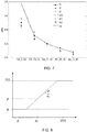
- Figure 9 shows a large set of 3D US abdominal acquisitions.
- the lines show the identified spine orientations.
- Each image is annotated by a clinician to identify the locations of landmarks such as the heart and stomach, and these are shown as dots. These landmarks annotated images are used to create the training database which implements machine learning.
- Figure 9 shows the high variability of fetus positions and orientations and confirms that learning on such a database will include variability due to spatial positioning instead of focusing on real anatomical variations.
- the 3D orientation (and scaling) process explained above gives rise to the images shown in Figure 10 .
- the heart locations are generally approximately in the area 80 and the stomach locations are generally approximately in the area 82.
- the training database uses machine learning based on the annotated images in order to learn landmark (e.g. organ) positions.
- the machine learning may be based on a random forest algorithm (for example disclosed in Criminisi, A., J., S., Konukoglu, E.: Decision forests: A unified framework for classification, regression, density estimation, manifold learning and semi-supervised learning. Foundations and Trends in Computer Graphics and Vision (2012 ).
- An approach may be used as disclosed in Cuingnet, R., Prevost, R., Lesage, D., Cohen, L.D., Mory, B., Ardon, R.: Automatic Detection and Segmentation of Kidneys in 3D CT Images using Random Forests. In: Proceedings of MICCAI'12. vol. 7512, pp. 66-74 (2012 ).
- the principle is to learn, for a given point in a volume, the relative direction to the target landmarks.
- a relative direction is referred to as a voting vector.
- the algorithm In order to train the random forest algorithm, it is necessary to set the values of a number of parameters.
- the most influential ones are the following: number of trees NT, depth of trees DT, number of training points NP per image, and threshold ⁇ on variance of voting vectors in a node.
- the algorithm also depends on image-based features (f).
- the features are for example mostly derived from local gradients, such as locally normalized gradients and distances to gradients.
- a splitting criterion is defined for all nodes. It aims at finding two subsets of training points so that the sum of the entropy of both subsets is minimal.
- the splitting criterion is obtained by testing a large set of random features at each node. Within this set, the feature that provides the optimal subset separation is selected together with the corresponding splitting threshold ( ⁇ ) and stored in the node.
- the entropy criterion is defined as the variance of the voting vectors to each landmark.
- the purpose of the training database is to enable automated identification of landmarks in a non-annotated 3D image volume.
- a scanned image is subjected to the same orientation, scaling and intensity normalization as explained above.
- the actual landmark localization process is restricted to the volume area located inside the abdomen convex hull. For a given input volume, the following steps are performed:
- all predictions are combined through Gaussian estimation to convert a set of all predictions into a single extracted prediction.
- Each clinical plane may be defined by three landmarks.
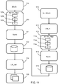
- FIG. 11 shows methods in accordance with the invention.
- the right side shows a method of generating the training database. It comprises: in step 110 receiving a training set of N 3D fetal ultrasound images. These include annotations from clinicians. Thus, in step 112, identification of landmarks within each 3D fetal ultrasound image of the training set is received.
- each 3D fetal ultrasound image of the training set is processed using the method as described above, to provide at least 3D re-orientation.
- step 114a This involves detecting the spine within the image in step 114a, determining the first reference axis (z) based on the spine (12) orientation and location within the image in step 114b.
- step 114c the second reference axis (x) is determined, perpendicular to the first reference axis (z), based on the fetal torso orientation with respect to the detected spine.
- intensity normalization and scaling is carried out in normalization step 115.
- This processing results in orientation of each 3D fetal ultrasound image of the training set using the respective first and second reference axes.
- step 116 machine learning is applied to the oriented training set to provide an algorithm which can determine the location of landmarks for a 3D fetal ultrasound image without corresponding identification of landmarks.
- a particular method is used for determining the head/toe orientation of the fetus (during the step 114).
- the plane of interest defined by the first and second reference axes is extracted, in particular the xz plane, and patches of a determined patch size are randomly sampled.
- a classifier is then based on the patches, wherein the classifier indicates the head/toe orientation of the fetus.
- the left side of Figure 11 shows the method of identifying landmarks within a new (meaning not included in the training database) 3D fetal ultrasound image.
- the method comprises in step 118 receiving a 3D fetal ultrasound image. This may be in real time, but equally the method may be applied to a stored image.
- step 120 the 3D fetal ultrasound image is re-oriented and then preferably rescaled and intensity normalized in step 121, using the method as described above.
- steps of detecting the spine 120a, determining the first reference axis (z) 120b and determining the second reference axis (x) in step 120c are again steps of detecting the spine 120a, determining the first reference axis (z) 120b and determining the second reference axis (x) in step 120c.
- the 3D fetal ultrasound image is re-oriented using the first and second reference axes generated by the method described above.
- step 122 the re-oriented 3D fetal ultrasound image is analyzed using the machine learning algorithm derived from the training database (from step 116) which comprises landmark information thereby to locate corresponding landmark information for the 3D fetal ultrasound image.
- the landmark positions are output in step 124.
- step 126 the landmark positions are used to automatically define image slices to be generated from the 3D ultrasound volume.
- the invention is for use for processing 3D fetal ultrasound images using a diagnostic imaging system.
- the system comprises an array transducer probe 210 which has a CMUT transducer array 200 for transmitting ultrasound waves and receiving echo information.
- the transducer array 200 may alternatively comprise piezoelectric transducers formed of materials such as PZT or PVDF.
- the transducer array 200 is a two-dimensional array of transducers 201 capable of scanning in three dimensions for 3D imaging.
- the transducer array 200 is coupled to a microbeamformer 212 in the probe which controls reception of signals by the CMUT array cells or piezoelectric elements.
- Microbeamformers are capable of at least partial beamforming of the signals received by subarrays (or "groups” or “patches") of transducers as described in US Patents 5,997,479 (Savord et al. ), 6,013,032 (Savord ), and 6,623,432 (Powers et al. ).
- microbeamformer is entirely optional.
- the examples below assume no analog beamforming.
- the microbeamformer 212 is coupled by the probe cable to a transmit/receive (T/R) switch 216 which switches between transmission and reception and protects the main beamformer 220 from high energy transmit signals when a microbeamformer is not used and the transducer array is operated directly by the main system beamformer.
- T/R transmit/receive
- the transmission of ultrasound beams from the transducer array 210 is directed by a transducer controller 218 coupled to the microbeamformer by the T/R switch 216 and a main transmission beamformer (not shown), which receives input from the user's operation of the user interface or control panel 238.
- One of the functions controlled by the transducer controller 218 is the direction in which beams are steered and focused. Beams may be steered straight ahead from (orthogonal to) the transducer array, or at different angles for a wider field of view.
- the transducer controller 218 can be coupled to control a DC bias control 245 for the CMUT array.
- the DC bias control 245 sets DC bias voltage(s) that are applied to the CMUT cells.
- partially beamformed signals are produced by the microbeamformer 212 and are coupled to a main receive beamformer 220 where the partially beamformed signals from individual patches of transducers are combined into a fully beamformed signal.
- the main beamformer 220 may have 128 channels, each of which receives a partially beamformed signal from a patch of dozens or hundreds of CMUT transducer cells or piezoelectric elements. In this way the signals received by thousands of transducers of a transducer array can contribute efficiently to a single beamformed signal.
- the beamformed reception signals are coupled to a signal processor 222.
- the signal processor 222 can process the received echo signals in various ways, such as band-pass filtering, decimation, I and Q component separation, and harmonic signal separation which acts to separate linear and nonlinear signals so as to enable the identification of nonlinear (higher harmonics of the fundamental frequency) echo signals returned from tissue and micro-bubbles.
- the signal processor may also perform additional signal enhancement such as speckle reduction, signal compounding, and noise elimination.
- the band-pass filter in the signal processor can be a tracking filter, with its pass band sliding from a higher frequency band to a lower frequency band as echo signals are received from increasing depths, thereby rejecting the noise at higher frequencies from greater depths where these frequencies are devoid of anatomical information.
- the beamformers for transmission and for reception are implemented in different hardware and can have different functions.
- the receiver beamformer is designed to take into account the characteristics of the transmission beamformer.
- Figure 12 only the receiver beamformers 212, 220 are shown, for simplicity. In the complete system, there will also be a transmission chain with a transmission micro beamformer, and a main transmission beamformer.
- the function of the micro beamformer 212 is to provide an initial combination of signals in order to decrease the number of analog signal paths. This is typically performed in the analog domain.
- the final beamforming is done in the main beamformer 220 and is typically after digitization.
- the transmission and reception channels use the same transducer array 210 which has a fixed frequency band. However, the bandwidth that the transmission pulses occupy can vary depending on the transmission beamforming that has been used.
- the reception channel can capture the whole transducer bandwidth (which is the classic approach) or by using bandpass processing it can extract only the bandwidth that contains the useful information (e.g. the harmonics of the main harmonic).
- the processed signals are coupled to a B mode (i.e. brightness mode, or 2D imaging mode) processor 226 and a Doppler processor 228.
- the B mode processor 226 employs detection of an amplitude of the received ultrasound signal for the imaging of structures in the body such as the tissue of organs and vessels in the body.
- B mode images of structure of the body may be formed in either the harmonic image mode or the fundamental image mode or a combination of both as described in US Pat. 6,283,919 (Roundhill et al. ) and US Pat. 6,458,083 (Jago et al. )
- the Doppler processor 228 processes temporally distinct signals from tissue movement and blood flow for the detection of the motion of substances such as the flow of blood cells in the image field.
- the Doppler processor 228 typically includes a wall filter with parameters which may be set to pass and/or reject echoes returned from selected types of materials in the body.
- the structural and motion signals produced by the B mode and Doppler processors are coupled to a scan converter 232 and a multi-planar reformatter 244.
- the scan converter 232 arranges the echo signals in the spatial relationship from which they were received in a desired image format. For instance, the scan converter may arrange the echo signal into a two dimensional (2D) sector-shaped format, or a pyramidal three dimensional (3D) image.
- the scan converter can overlay a B mode structural image with colors corresponding to motion at points in the image field with their Doppler-estimated velocities to produce a color Doppler image which depicts the motion of tissue and blood flow in the image field.
- the multi-planar reformatter will convert echoes which are received from points in a common plane in a volumetric region of the body into an ultrasound image of that plane, as described in US Pat. 6,443,896 (Detmer ).
- a volume renderer 242 converts the echo signals of a 3D data set into a projected 3D image as viewed from a given reference point as described in US Pat. 6,530,885 (Entrekin et al. ).
- the 2D or 3D images are coupled from the scan converter 232, multi-planar reformatter 244, and volume renderer 242 to an image processor 230 for further enhancement, buffering and temporary storage for display on an image display 240.
- the blood flow values produced by the Doppler processor 28 and tissue structure information produced by the B mode processor 226 are coupled to a quantification processor 234.
- the quantification processor produces measures of different flow conditions such as the volume rate of blood flow as well as structural measurements such as the sizes of organs and gestational age.
- the quantification processor may receive input from the user control panel 238, such as the point in the anatomy of an image where a measurement is to be made.
- Output data from the quantification processor is coupled to a graphics processor 236 for the reproduction of measurement graphics and values with the image on the display 240, and for audio output from the display device 240.
- the graphics processor 236 can also generate graphic overlays for display with the ultrasound images. These graphic overlays can contain standard identifying information such as patient name, date and time of the image, imaging parameters, and the like.
- the graphics processor receives input from the user interface 238, such as patient name.
- the user interface is also coupled to the transmit controller 218 to control the generation of ultrasound signals from the transducer array 210 and hence the images produced by the transducer array and the ultrasound system.
- the transmit control function of the controller 218 is only one of the functions performed.
- the controller 218 also takes account of the mode of operation (given by the user) and the corresponding required transmitter configuration and band-pass configuration in the receiver analog to digital converter.
- the controller 218 can be a state machine with fixed states.
- the user interface is also coupled to the multi-planar reformatter 244 for selection and control of the planes of multiple multi-planar reformatted (MPR) images which may be used to perform quantified measures in the image field of the MPR images.
- MPR multi-planar reformatted
- the image processing functions described above may for example be performed by the image processor 230.
Description
- This invention relates to the processing of fetal ultrasound images.
- In a clinical setting, 2D ultrasound (US) is the preferred scanning protocol for biometry measurements, growth monitoring and anatomy assessment during pregnancy. Obtaining reproducible and accurate values requires strict guidelines to be followed, especially regarding the selection of the standard 2D viewing planes which are used to search for abnormalities or perform biometry measurements such as head and abdomen circumference or femur length. This task can be very difficult because of multiple factors, such as the mother morphology, the unknown and highly variable orientation of the fetus as well as well-known US artefacts, in particular the shadowing effect.
- 3D US is a more recent imaging technique that has the potential to overcome some of the above mentioned difficulties. In particular, the acquisition of a single 3D volume makes it possible to select the required viewing planes. In addition, the clinicians can perform offline reading and, if necessary, adjust the position of the extracted planes (called "clinical planes") prior to standard measurements.
- It would be desirable to process 3D US volumes automatically to enable extraction of the targeted clinical planes. However this task is challenging due to the high variability of the fetus orientation at the acquisition time. Various strategies have been proposed for automatic viewing plane extraction in 2D. Views of interest can be selected from 2D US sequences by classifying the content of each frame to determine if it corresponds to a standard plane using a radial component model or a pre-trained recurrent neural network.
- Document
US 2010/099987 A1 describes an ultrasonic image acquisition and diagnosis display technique in which the spine of a fetus included in a 3D volume scan is used as a landmark for recognizing the position of the heart in the chest of the fetus with high accuracy. - Another 2D approach consists in fitting geometrical templates built at multiple resolutions and orientations in order to label the anatomical content.
- There remains a need for a more reliable automated approach for extracting information of interest from a 3D fetal US image.
- According to the invention, there is provided a computer implemented method for processing a 3D fetal ultrasound image according to appended
claim 1. - This method enables alignment of a 3D volume image using two reference axes, in order to provide a normalized representation which removes variation resulting from different fetus orientations. A first reference axis is based on the spine, and it may be the direction of the spine in the middle of the spine, or it may be the direction of the vector connecting identified end points of the spine, for example. The spine is a well-defined, unique structure within the fetus that will be readily recognizable to the ultrasound system, particularly when using image recognition techniques.
- The second reference axis enables volume rotation about the spine (i.e. about the first reference axis), so that a 3D orientation of the fetus is identified.
- The updated image may be a rotated version of the image, or it may be the image with additional data annotations identifying the reference axes.
- The method may be implemented in real time, so that the 3D ultrasound image is obtained by an ultrasound scan as part of the method. Alternatively, the method may be applied to a previously captured image.
- By providing a normalized volume orientation, identification of landmark points (such as organs) within the image is made possible by an automated machine learning approach. The method may for example be used to process samples of a training database to provide a machine learning operation, and then the machine learned algorithm may be used to process an unseen captured image (i.e. one not included already processed to create the training database) to provide automated identification.
- The invention may be considered to provide an image filtering or normalization process which can be applied before applying machine learning approaches in order to perform automatic extraction of the clinical planes of interest.
- The determining of the second reference axis comprises:
- extracting a set of planes, each orthogonal to the first reference axis or locally orthogonal to the spine;
- detecting an elliptical or circular form of the abdomen or thorax of the fetus in each plane; and
- determining the second reference axis based on an orientation vector in each plane between the spine and the center of the elliptical form.
- The spine is at one edge of the abdomen/thorax, so the vector between the spine and the center of the ellipse (or circle) represents a rotational orientation. In this way, it is possible to normalize the orientation of the 3D volume images based on the torso/abdominal shape of the fetus. As the torso/abdomen is the largest portion of the fetus, it is easily measurable, thereby increasing the accuracy of the alignment.
- The elliptical or circular form is for example obtained by performing a Hankel transform on the plane.
- The generating of the second reference axis may comprise:
- projecting the orientation vectors on a central plane located at the middle of the spine; taking an average of the projected orientation vectors; and
- using the average of the projected orientation vectors to form the second reference axis.
- By generating the transverse axis based on an average of the projected orientation values, a second reference axis is obtained which is reliably consistent between different images.
- Taking an average may comprise calculating a weighted average, with greater weighting in the middle of the spine than at the ends of the spine.
- The method may further comprise:
- determining a head/toe orientation of the 3D fetal ultrasound image; and
- updating the 3D fetal ultrasound image using the head/toe orientation.
- This involves determining the orientation of the 3D images with respect to the up-down fetus position, i.e. to determine at which end of the spine is the head at which end is the buttocks (and then the legs down to the toes). This may be considered to be an elevation orientation. The updating may again comprise an image manipulation or annotation of the image with an up/down indication.
- The method may further comprise:
- performing intensity normalization on the 3D fetal ultrasound image; and/or
- scaling the 3D fetal ultrasound image based on a fetal gestation age.
- In this way, the scale variability between 3D fetal ultrasound images due to gestation age is reduced, and/or the intensity variation due to varying image acquisition gains and imaging conditions may be reduced. The scaling and intensity normalization may take place before or after the reference axis determination and re-orientation.
- The detecting of the spine within the 3D fetal ultrasound image for example comprises:
- analyzing the image with a morphological filter adapted to detect elongated bright structures;
- analyzing the image with a deep learning-based vertebrae detector; and
- obtaining a spine mask based on the responses from the morphological filter and from the deep learning-based vertebrae detector.
- The spine mask is preferably a binary mask.
- In this way, the detection of the spine takes advantages of the strengths of both methods, so that the position of the spine within the 3D fetal ultrasound image can be more robustly determined.
- The invention also provides a method of generating a training database based on 3D fetal ultrasound images and generating an algorithm, comprising:
- receiving a training set of 3D fetal ultrasound images;
- receiving identification of landmarks within each 3D fetal ultrasound image of the training set;
- processing each 3D fetal ultrasound image of the training set using the method as defined above;
- orienting each 3D fetal ultrasound image of the training set using the respective first and second reference axes and head/toe orientation; and
- using machine learning to the oriented training set to provide an algorithm which can determine the location of landmarks for a 3D fetal ultrasound image without corresponding identification of landmarks.
- The landmark identifications in the received training set are for example manually provided by a clinician. These provide the information for a machine learning algorithm to be able to identify the landmarks in a new image. The landmarks are for example organs, such as the heart, bladder, kidneys and umbilical insertion.
- During the training database generation, the method may comprise determining the head/toe orientation of the fetus by:
- extracting a plane of interest defined by the first and second reference axes;
- randomly sampling patches, of a determined patch size, of the extracted plane of interest; and
- generating a classifier based on the patches, wherein the classifier indicates the head/toe orientation of the fetus.
- By generating a classifier for a 3D volume image based on randomly sampled patches of an extracted plane, it is possible to efficiently represent the orientation of the 3D volume image, for example as a binary indicator. The patch size is for example based on a fetal gestation age and a resolution of the 3D fetal ultrasound image.
- The invention also provides a method of identifying landmarks within a 3D fetal ultrasound image, comprising:
- receiving a 3D fetal ultrasound image;
- processing the 3D fetal ultrasound image using the method as defined above;
- orienting the 3D fetal ultrasound image using the first and second reference axes; and
- analyzing the oriented 3D fetal ultrasound image with a machine learning algorithm derived from a training database which comprises landmark information, thereby to locate corresponding landmark information for the 3D fetal ultrasound image.
- This method provides identification of landmarks using the previous machine learning from the testing database, so that the landmarks may be located in an automated way. The 3D orientation processing removes or reduces uncertainties resulting from unknown fetal positions.
- The identified landmarks may then be used to control the generation of 2D image planes of interest, namely planes which pass through organs or other landmarks of interest, or are defined with respect to the position of such organs or other landmarks.
- The training database used in this method is generated using the method as defined above.
- The invention also provides a computer program and a controller for controlling the processing a 3D fetal ultrasound image, wherein the controller comprises instructions thereon that when executed cause the controller to implement the methods defined above.
- The invention also provides an ultrasound system, the system comprising:
- an ultrasonic probe, the ultrasonic probe comprising an array of transducer elements, wherein the ultrasonic probe is adapted to obtain a 3D fetal ultrasound image of a region of interest;
- a controller as defined above ; and
- a display device for displaying the aligned 3D fetal ultrasound image,
- wherein the controller is adapted to analyze the updated 3D fetal ultrasound image using a machine learning algorithm derived from a training database, thereby to derive landmark locations within the 3D fetal ultrasound image.
- Examples of the invention will now be described in detail with reference to the accompanying drawings, in which:
-
Figure 1 shows a representation of a fetus with the xyz referential axes allocated to the fetus as proposed in the invention; -
Figure 2 shows a randomly oriented spine and a rotated version to a defined vertical orientation; -
Figure 3 shows the spine with four xy imaging planes spaced along the spine; -
Figure 4 shows the set of located circles or ellipses along the spine planes as well as their center points; -
Figure 5 shows an xz plane within the general volume; -
Figure 6 shows two images in the xz plane with opposite orientation of the fetus; -
Figure 7 shows a scaling function graphically; -
Figure 8 is an illustration of an intensity normalization look-up-table; -
Figure 9 shows a large set of 3D US abdominal acquisitions with lines to show the identified spine orientations and dots as the locations of landmarks; -
Figure 10 shows the 3D US abdominal acquisitions after re-orientation and scaling; -
Figure 11 shows methods in accordance with the invention; and -
Figure 12 shows an exemplary ultrasound diagnostic imaging system. - The invention provides a computer implemented method for processing a 3D fetal ultrasound image. A 3D fetal ultrasound image is obtained (either acquired or received from memory), and the spine is detected within the image. This enables a first reference axis to be defined. A second reference axis is defined perpendicular to the first reference axis, and the 3D fetal ultrasound image is updated (e.g. rotated in 3D space) using the first and second reference axes and an up/down (elevation) orientation detection. This provides a normalization of the orientation of the image, so that a machine learning approach is better able to identify landmarks within new images.
-
Figure 1 shows a representation of a fetus comprising ahead 10 andspine 12. The fetus is positioned within 3D space as defined by the axes x,y,z and with an origin at the center of the spine. - When selecting 2D ultrasound image planes from a 3D ultrasound scan, planes are selected to pass through landmarks of interest. These landmarks are typically organs or other anatomical features such as the
stomach 14,heart 16 orumbilical insertion 18. - This invention relates to an alignment procedure by which an image is aligned in a consistent way in 3D space before further image analysis. The further image analysis may be for locating the landmarks so that desired imaging planes may be automatically generated, or it may be for populating a training database.
- Thus. the method of the invention may be used for individual image analysis and/or for image analysis to populate a training database.
- The first step in the method is to detect the spine and derive a first reference (orientation) axis.
- The spine may be automatically detected in a 3D ultrasound image by combining a morphological filter which detects elongated bright structures and a deep learning (DL) based vertebrae detector, in order to take advantage of the strengths of both methods.
- A morphological filter may be used. for each voxel x in the US volume in a given spherical neighborhood, to compare the intensity of the voxels along a direction u with the intensity of the other voxels. The filter responses are computed for various neighborhood radii and orientations u and combined to obtain a global response. The global responses of neighboring voxels are aggregated to define connected components which correspond to the best filter responses.
- Although some of the responses are accurately positioned on the spine using this approach, others may also be present which are outliers, that may for example be located on ribs or other elongated structures such as long bones.
- The deep learning-based vertebrae detector is a 2D fully convolutional network whose input is made of 2D slices, extracted orthogonally to the original identified z-axis. The volume slicing produces a large amount of data with similar features, which is appropriate for deep learning methods. The network output is a down sampled probability map, with values closer to 1 where the spine might be located. A 3D deep learning-based vertebrae detector is formed by stacking all the obtained 2D probability maps for one volume. This output heatmap is coarser than the morphological filter output, but more robustly located around the vertebrae.
- By combining the deep-learning vertebrae detector and the morphological filter responses, the network output is refined and the filter responses that are outside the spine are rejected, so that a robust spine binary mask is finally obtained.
- This is one way to identify the spine location, but any other suitable image processing techniques may be employed for detecting the unique spine shape.
-
Figure 2 shows on the left a randomly orientedspine 12. The spine detection basically involves identifying the spine, and using the center of mass of the spine binary mask to define the origin O of a reference coordinate system. If the detected spine is highly curved, its center of mass might not belong to the binary mask. This is because the so-called barycenter of the spine can be outside the spine itself and hence not aligned with the mask. In this case, the binary mask point that is the closest to the center of mass is used. Then theextremities 20 of the spine binary mask are used to define the vertical z axis. Alternatively a normal direction tangential to the central point of the spine may be used. The resulting z axis is shown inFigure 1 . - By defining the z axis, the image can be updated to include the z axis information, for example by rotating the image to position the z-axis in the defined (e.g. vertical) orientation, as shown in the right part of
Figure 2 . - The second step in the method is to detect a second, orthogonal reference (orientation) axis. This is based on detection of the abdomen to define a transverse axis.
- A set of planes are searched, each orthogonal to the first reference axis z (or locally orthogonal to the spine). Searching for an orientation axis is conducted in a set of xy planes, each passing through a local origin, with the local origins as evenly spaced points along the spine.
-
Figure 3 shows thespine 12 with four xy imaging planes spaced along the spine. The images are shown to the right. - Within each of these 2D images, abdomen detection takes place, for example using a variant of the Hough transform, tailored to the detection of circular or elliptical shapes. In practice, the best convolution of the image with a radially-symmetric kernel modeling a disk with the desired border profile is searched among a range of radii.
- A resulting located circle is shown in each image.
-
Figure 4 shows the set of located circles orellipses 40 along the spine planes as well as their center points 42. The convex hull the abdomen is defined. - For each plane, there is computation of the vector going from the spine intersection with the plane to the center of the detected circle. These vector arrows are shown in
Figure 3 , and onesuch vector 44 is shown inFigure 4 . - The abdomen detection thus involves detecting an elliptical or circular form of the abdomen or thorax of the fetus in each plane, and identifying a vector within each plane which relates to the rotational orientation of the fetus in that plane.
- All of these vectors are then projected onto the transverse plane through the central origin O. The x axis reference direction is then defined as an average projected vector in this reference xy plane. The resulting x axis is shown in
Figure 1 and it defines a second reference axis. From these two axes, the third coordinate axis, y, may be chosen to be orthogonal with right-handed orientation. - The average vector may comprise a weighted average, with greater weighting in the middle of the spine than at the ends of the spine.
- Thus, by measuring two reference axes and then defining the third in a deterministic way, a normalized orientation in 3D space may be defined.
- It is next desirable to identify the head-toe orientation of the volume and choose between the two possible directions of the z axis.
- This may be achieved by training a classifier to distinguish between the two configurations in a 2D slice of the volume in the xz plane.
-
Figure 5 shows anxz plane 50 within thegeneral volume 52 which passes through theorigin 0. This plane passes along the spine. -
Figure 6 shows two images in the xz plane with opposite orientation of the fetus. Using image recognition approaches, the orientation can be identified based on previous machine learning from a testing set. A convolutional neural network may be used for this purpose. - For the machine learning step (to provide the reference for the image recognition), in order to be robust to possible inaccuracies during the spine detection step, random noise may be added during the xz slice extraction so that the network is fed with corrupted data during the training. Then, random patches are selected in the slice to train the classifier. The patch size may be selected based on gestational age and image resolution so that all structures have a normalized size. The output is binary 1 when the fetus head is at the top of the image, binary 0 if it is at the bottom.
- The eventual detection of the orientation in use when analyzing a single image is implemented with a similar process, without the random noise addition.
- The method steps explained above enable the fetal image to be mapped to a known orientation in 3D space.
- To reduce scale variability due to varying gestational ages (GA), a scaling factor may also be applied to all volumes based on existing growth tables, for example before the orientation mapping.
- For example the table below shows scaling factors for different gestational age ("GA") ranges (in weeks).
GA_0_20 2,43 GA_20_25 1,30 GA_25_30 1,00 GA_30_35 0,83 GA_35_42 0,70 -
Figure 7 shows this scaling function graphically. The y-axis plots the scaling ratio, and the x-axis plots the gestational age ranges. The points show the distances to the origin for different anatomical features (H heart, S stomach, B bladder, UV umbilical vein,K1 kidney 1, K2 kidney 2, UI umbilical insertion). - For each volume, the distance between an organ, for example the Heart (H), and the origin O (as defined above) is measured. The examinations are grouped per GA range into the five groups shown. Within each group, the average distance for each organ is computed. The GA_25_30 group is used as a reference (hence the perfect alignment of all organs for the the
GA 25 30 group with the plot, with a ration value of 1) and each averaged distance in each group is divided by the values obtained in group GA_25_30. The results are plotted as the points in the graph. The continuous curve represents the theoretical ratios presented in the table above. The discrepancy between the measured values and the theoretical ratios results from the sample set used, and in particular the spread of samples within each GA range. - The method may also provide intensity normalization. Due to varying acquisition gains and imaging conditions, the relative intensity of various organs may vary significantly. Intensity normalization is desirable to assist the feature extraction in the machine learning approach. One approach is to use the mean and standard deviation, using a common normalization look up table.
-
Figure 8 is an illustration of a database look-up-table to perform intensity normalization of ultrasound acquisitions. The x-axis shows the intensity range for a particular image, with mean intensity µi and standard deviation σi of the pixel intensity values. The database provides an intensity mapping so that each image is transformed to have a reference standard deviation σ and a reference mean µ. The reference intensity characteristics are shown by the y-axis. - Thus, the 3D image volumes are rotated, translated, intensity scaled, and size scaled so that the associated fetus landmarks are perfectly aligned with respect to a common reference.
- The method above may be used to process a single captured 3D ultrasound image or to create the training database (as already mentioned above). These two uses of the method will now be explained.
-
Figure 9 shows a large set of 3D US abdominal acquisitions. The lines show the identified spine orientations. Each image is annotated by a clinician to identify the locations of landmarks such as the heart and stomach, and these are shown as dots. These landmarks annotated images are used to create the training database which implements machine learning. -
Figure 9 shows the high variability of fetus positions and orientations and confirms that learning on such a database will include variability due to spatial positioning instead of focusing on real anatomical variations. - The 3D orientation (and scaling) process explained above gives rise to the images shown in
Figure 10 . The heart locations are generally approximately in thearea 80 and the stomach locations are generally approximately in thearea 82. - These aligned images are instead used for a learning-based approach, which then enables more robust detection of the fetus landmark positions.
- The training database uses machine learning based on the annotated images in order to learn landmark (e.g. organ) positions. The machine learning may be based on a random forest algorithm (for example disclosed in Criminisi, A., J., S., Konukoglu, E.: Decision forests: A unified framework for classification, regression, density estimation, manifold learning and semi-supervised learning. Foundations and Trends in Computer Graphics and Vision (2012). An approach may be used as disclosed in Cuingnet, R., Prevost, R., Lesage, D., Cohen, L.D., Mory, B., Ardon, R.: Automatic Detection and Segmentation of Kidneys in 3D CT Images using Random Forests. In: Proceedings of MICCAI'12. vol. 7512, pp. 66-74 (2012).
- The principle is to learn, for a given point in a volume, the relative direction to the target landmarks. In the following description, such a relative direction is referred to as a voting vector.
- In order to train the random forest algorithm, it is necessary to set the values of a number of parameters. The most influential ones are the following: number of trees NT, depth of trees DT, number of training points NP per image, and threshold α on variance of voting vectors in a node. The algorithm also depends on image-based features (f). The features are for example mostly derived from local gradients, such as locally normalized gradients and distances to gradients.
- A splitting criterion is defined for all nodes. It aims at finding two subsets of training points so that the sum of the entropy of both subsets is minimal. The splitting criterion is obtained by testing a large set of random features at each node. Within this set, the feature that provides the optimal subset separation is selected together with the corresponding splitting threshold (θ) and stored in the node. The entropy criterion is defined as the variance of the voting vectors to each landmark.
- Multiple stopping criteria are defined for all leaves: (i) when a given depth DT of the tree is reached, (ii) when the intra-subset variance is below a given threshold α, (iii) when the subset is too small. The mean of the voting vectors is stored in each leaf. This will be the voting vector of each point classified in this leaf.
- This is just one generic description of how machine learning may be used to train a database for identification of landmarks, having positions relative to an identified structure. Of course, other pattern recognition approaches may be used.
- The purpose of the training database is to enable automated identification of landmarks in a non-annotated 3D image volume.
- For this purpose, a scanned image is subjected to the same orientation, scaling and intensity normalization as explained above.
- The actual landmark localization process is restricted to the volume area located inside the abdomen convex hull. For a given input volume, the following steps are performed:
- P random testing points are selected;
- the testing points are propagated throughout the tree, using the (f, θ) splitting and feature criteria, until they reach a leaf;
- each point provides a voting vector; and
- all voting vectors are converted into landmark predictions.
- To provide a single prediction, all predictions are combined through Gaussian estimation to convert a set of all predictions into a single extracted prediction.
- When landmarks have been identified, they may be used for the automatic extraction of clinical planes. Each clinical plane may be defined by three landmarks.
-
Figure 11 shows methods in accordance with the invention. - The right side shows a method of generating the training database. It comprises:
instep 110 receiving a training set ofN 3D fetal ultrasound images. These include annotations from clinicians. Thus, instep 112, identification of landmarks within each 3D fetal ultrasound image of the training set is received. - In
step 114, each 3D fetal ultrasound image of the training set is processed using the method as described above, to provide at least 3D re-orientation. - This involves detecting the spine within the image in
step 114a, determining the first reference axis (z) based on the spine (12) orientation and location within the image instep 114b. Instep 114c, the second reference axis (x) is determined, perpendicular to the first reference axis (z), based on the fetal torso orientation with respect to the detected spine. - Preferably also intensity normalization and scaling is carried out in
normalization step 115. This processing results in orientation of each 3D fetal ultrasound image of the training set using the respective first and second reference axes. - In
step 116 machine learning is applied to the oriented training set to provide an algorithm which can determine the location of landmarks for a 3D fetal ultrasound image without corresponding identification of landmarks. - As explained above, when generating the training database, a particular method is used for determining the head/toe orientation of the fetus (during the step 114). The plane of interest defined by the first and second reference axes is extracted, in particular the xz plane, and patches of a determined patch size are randomly sampled. A classifier is then based on the patches, wherein the classifier indicates the head/toe orientation of the fetus.
- The left side of
Figure 11 shows the method of identifying landmarks within a new (meaning not included in the training database) 3D fetal ultrasound image. - The method comprises in
step 118 receiving a 3D fetal ultrasound image. This may be in real time, but equally the method may be applied to a stored image. - In
step 120, the 3D fetal ultrasound image is re-oriented and then preferably rescaled and intensity normalized instep 121, using the method as described above. There are again steps of detecting thespine 120a, determining the first reference axis (z) 120b and determining the second reference axis (x) instep 120c. The 3D fetal ultrasound image is re-oriented using the first and second reference axes generated by the method described above. - In
step 122 the re-oriented 3D fetal ultrasound image is analyzed using the machine learning algorithm derived from the training database (from step 116) which comprises landmark information thereby to locate corresponding landmark information for the 3D fetal ultrasound image. - Optionally, the landmark positions are output in
step 124. - In
step 126, the landmark positions are used to automatically define image slices to be generated from the 3D ultrasound volume. - The invention is for use for processing 3D fetal ultrasound images using a diagnostic imaging system.
- For completeness, the general operation of an exemplary ultrasound diagnostic imaging system will first be described, with reference to
Figure 12 , and with emphasis on the signal processing function of the system since this invention relates to the processing of the signals measured by the transducer array. - The system comprises an
array transducer probe 210 which has aCMUT transducer array 200 for transmitting ultrasound waves and receiving echo information. Thetransducer array 200 may alternatively comprise piezoelectric transducers formed of materials such as PZT or PVDF. Thetransducer array 200 is a two-dimensional array oftransducers 201 capable of scanning in three dimensions for 3D imaging. - The
transducer array 200 is coupled to amicrobeamformer 212 in the probe which controls reception of signals by the CMUT array cells or piezoelectric elements. Microbeamformers are capable of at least partial beamforming of the signals received by subarrays (or "groups" or "patches") of transducers as described inUS Patents 5,997,479 (Savord et al. ),6,013,032 (Savord ), and6,623,432 (Powers et al. ). - Note that the microbeamformer is entirely optional. The examples below assume no analog beamforming.
- The
microbeamformer 212 is coupled by the probe cable to a transmit/receive (T/R)switch 216 which switches between transmission and reception and protects themain beamformer 220 from high energy transmit signals when a microbeamformer is not used and the transducer array is operated directly by the main system beamformer. The transmission of ultrasound beams from thetransducer array 210 is directed by atransducer controller 218 coupled to the microbeamformer by the T/R switch 216 and a main transmission beamformer (not shown), which receives input from the user's operation of the user interface orcontrol panel 238. - One of the functions controlled by the
transducer controller 218 is the direction in which beams are steered and focused. Beams may be steered straight ahead from (orthogonal to) the transducer array, or at different angles for a wider field of view. Thetransducer controller 218 can be coupled to control aDC bias control 245 for the CMUT array. The DC biascontrol 245 sets DC bias voltage(s) that are applied to the CMUT cells. - In the reception channel, partially beamformed signals are produced by the
microbeamformer 212 and are coupled to a main receivebeamformer 220 where the partially beamformed signals from individual patches of transducers are combined into a fully beamformed signal. For example, themain beamformer 220 may have 128 channels, each of which receives a partially beamformed signal from a patch of dozens or hundreds of CMUT transducer cells or piezoelectric elements. In this way the signals received by thousands of transducers of a transducer array can contribute efficiently to a single beamformed signal. - The beamformed reception signals are coupled to a
signal processor 222. Thesignal processor 222 can process the received echo signals in various ways, such as band-pass filtering, decimation, I and Q component separation, and harmonic signal separation which acts to separate linear and nonlinear signals so as to enable the identification of nonlinear (higher harmonics of the fundamental frequency) echo signals returned from tissue and micro-bubbles. The signal processor may also perform additional signal enhancement such as speckle reduction, signal compounding, and noise elimination. The band-pass filter in the signal processor can be a tracking filter, with its pass band sliding from a higher frequency band to a lower frequency band as echo signals are received from increasing depths, thereby rejecting the noise at higher frequencies from greater depths where these frequencies are devoid of anatomical information. - The beamformers for transmission and for reception are implemented in different hardware and can have different functions. Of course, the receiver beamformer is designed to take into account the characteristics of the transmission beamformer. In
Figure 12 only thereceiver beamformers - The function of the
micro beamformer 212 is to provide an initial combination of signals in order to decrease the number of analog signal paths. This is typically performed in the analog domain. - The final beamforming is done in the
main beamformer 220 and is typically after digitization. - The transmission and reception channels use the
same transducer array 210 which has a fixed frequency band. However, the bandwidth that the transmission pulses occupy can vary depending on the transmission beamforming that has been used. The reception channel can capture the whole transducer bandwidth (which is the classic approach) or by using bandpass processing it can extract only the bandwidth that contains the useful information (e.g. the harmonics of the main harmonic). - The processed signals are coupled to a B mode (i.e. brightness mode, or 2D imaging mode)
processor 226 and aDoppler processor 228. TheB mode processor 226 employs detection of an amplitude of the received ultrasound signal for the imaging of structures in the body such as the tissue of organs and vessels in the body. B mode images of structure of the body may be formed in either the harmonic image mode or the fundamental image mode or a combination of both as described inUS Pat. 6,283,919 (Roundhill et al. ) andUS Pat. 6,458,083 (Jago et al. ) TheDoppler processor 228 processes temporally distinct signals from tissue movement and blood flow for the detection of the motion of substances such as the flow of blood cells in the image field. TheDoppler processor 228 typically includes a wall filter with parameters which may be set to pass and/or reject echoes returned from selected types of materials in the body. - The structural and motion signals produced by the B mode and Doppler processors are coupled to a
scan converter 232 and amulti-planar reformatter 244. Thescan converter 232 arranges the echo signals in the spatial relationship from which they were received in a desired image format. For instance, the scan converter may arrange the echo signal into a two dimensional (2D) sector-shaped format, or a pyramidal three dimensional (3D) image. The scan converter can overlay a B mode structural image with colors corresponding to motion at points in the image field with their Doppler-estimated velocities to produce a color Doppler image which depicts the motion of tissue and blood flow in the image field. The multi-planar reformatter will convert echoes which are received from points in a common plane in a volumetric region of the body into an ultrasound image of that plane, as described inUS Pat. 6,443,896 (Detmer ). Avolume renderer 242 converts the echo signals of a 3D data set into a projected 3D image as viewed from a given reference point as described inUS Pat. 6,530,885 (Entrekin et al. ). - The 2D or 3D images are coupled from the
scan converter 232,multi-planar reformatter 244, andvolume renderer 242 to animage processor 230 for further enhancement, buffering and temporary storage for display on animage display 240. In addition to being used for imaging, the blood flow values produced by the Doppler processor 28 and tissue structure information produced by theB mode processor 226 are coupled to aquantification processor 234. The quantification processor produces measures of different flow conditions such as the volume rate of blood flow as well as structural measurements such as the sizes of organs and gestational age. The quantification processor may receive input from theuser control panel 238, such as the point in the anatomy of an image where a measurement is to be made. Output data from the quantification processor is coupled to agraphics processor 236 for the reproduction of measurement graphics and values with the image on thedisplay 240, and for audio output from thedisplay device 240. Thegraphics processor 236 can also generate graphic overlays for display with the ultrasound images. These graphic overlays can contain standard identifying information such as patient name, date and time of the image, imaging parameters, and the like. For these purposes the graphics processor receives input from theuser interface 238, such as patient name. The user interface is also coupled to the transmitcontroller 218 to control the generation of ultrasound signals from thetransducer array 210 and hence the images produced by the transducer array and the ultrasound system. The transmit control function of thecontroller 218 is only one of the functions performed. Thecontroller 218 also takes account of the mode of operation (given by the user) and the corresponding required transmitter configuration and band-pass configuration in the receiver analog to digital converter. Thecontroller 218 can be a state machine with fixed states. - The user interface is also coupled to the
multi-planar reformatter 244 for selection and control of the planes of multiple multi-planar reformatted (MPR) images which may be used to perform quantified measures in the image field of the MPR images. - The image processing functions described above may for example be performed by the
image processor 230. - Other variations to the disclosed embodiments can be understood and effected by those skilled in the art in practicing the claimed invention, from a study of the drawings, the disclosure, and the appended claims. In the claims, the word "comprising" does not exclude other elements or steps, and the indefinite article "a" or "an" does not exclude a plurality. The mere fact that certain measures are recited in mutually different dependent claims does not indicate that a combination of these measures cannot be used to advantage. Any reference signs in the claims should not be construed as limiting the scope.
Claims (15)
- A computer implemented method for processing a 3D fetal ultrasound image, the method comprising:(110; 118) obtaining a 3D fetal ultrasound image;(114a, 120a) detecting the spine within the image;(114b, 120b) determining a first reference axis (z) based on the spine (12) orientation and location within the image;(114c, 120c) determining a second reference axis (x), perpendicular to the first reference axis (z), based on the fetal torso orientation with respect to the detected spine; andupdating the 3D fetal ultrasound image using the first and second reference axes;wherein the determining of the second reference axis (x) comprises:extracting a set of planes (40), each orthogonal to the first reference axis or locally orthogonal to the spine;detecting an elliptical or circular form of the abdomen or thorax of the fetus in each plane (40); anddetermining the second reference axis (x) based on an orientation vector (44) in each plane between the spine and the center of the elliptical form.
- A method as claimed in claim 1, wherein the elliptical form is obtained by performing a Hankel transform on the plane.
- A method as claimed in claim 1 or 2, wherein the generating of the second reference axis (x) comprises:projecting the orientation vectors (44) on a central plane located at the middle of the spine;taking an average of the projected orientation vectors; andusing the average of the projected orientation vectors to form the second reference axis (x).
- A method as claimed in claim 3, wherein taking an average comprises calculating a weighted average, with greater weighting in the middle of the spine than at the ends of the spine.
- A method as claimed in any preceding claim, wherein the method further comprises:determining a head/toe orientation of the 3D fetal ultrasound image; andupdating the 3D fetal ultrasound image using the head/toe orientation.
- A method as claimed in any preceding claim, wherein the method further comprises:(121, 115) performing intensity normalization on the 3D fetal ultrasound image; and/or(121, 115) scaling the 3D fetal ultrasound image based on a fetal gestation age.
- A method as claimed in any preceding claim, wherein the detecting of the spine within the 3D fetal ultrasound image comprises:analyzing the image with a morphological filter adapted to detect elongated bright structures;analyzing the image with a deep learning-based vertebrae detector; andobtaining a spine mask based on the responses from the morphological filter and from the deep learning-based vertebrae detector.
- A method of identifying landmarks within a 3D fetal ultrasound image, comprising:(118) receiving a 3D fetal ultrasound image;(120, 121) processing the 3D fetal ultrasound image using the method as claimed in any one of claims 1 to 7;(120, 121) orienting the 3D fetal ultrasound image using the first and second reference axes; and(122) analyzing the oriented 3D fetal ultrasound image with a machine learning algorithm derived from a training database which comprises landmark information, thereby to locate corresponding landmark information for the 3D fetal ultrasound image.
- A method of generating a training database based on 3D fetal ultrasound images and generating an algorithm, comprising:(110) receiving a training set of 3D fetal ultrasound images;(112) receiving identification of landmarks within each 3D fetal ultrasound image of the training set;(114, 115) processing each 3D fetal ultrasound image of the training set using the method as claimed in any preceding claim;(114, 115) orienting each 3D fetal ultrasound image of the training set using the respective first and second reference axes and head/toe orientation; and(116) using machine learning to the oriented training set to provide an algorithm which can determine the location of landmarks for a 3D fetal ultrasound image without corresponding identification of landmarks.
- A method as claimed in claim 9, comprising determining the head/toe orientation of the fetus during the processing of each 3D fetal ultrasound images by:extracting a plane of interest defined by the first (z) and second (x) reference axes;randomly sampling patches, of a determined patch size, of the extracted plane of interest; andgenerating a classifier based on the patches, wherein the classifier indicates the head/toe orientation of the fetus.
- A method as claimed in claim 10, wherein the patch size is based on a fetal gestation age and a resolution of the 3D fetal ultrasound image.
- A method as claimed in claim 8, wherein the machine learning algorithm is generated using the method as claimed in claim 9, 10 or 11.
- A computer program comprising computer program code means which is adapted, when said computer program is run on a computer, to implement the method of any one of claims 1 to 8.
- A controller for controlling the processing a 3D fetal ultrasound image, the controller comprising instructions thereon that when executed cause the controller to implement the method of any one of claims 1 to 8.
- An ultrasound system, the system comprising:an ultrasonic probe (210), the ultrasonic probe comprising an array (200) of transducer elements (201), wherein the ultrasonic probe is adapted to obtain a 3D fetal ultrasound image of a region of interest;a controller (230) as claimed in claim 14; anda display device (240) for displaying the aligned 3D fetal ultrasound image,wherein the controller (230) is adapted to analyze the updated 3D fetal ultrasound image using a machine learning algorithm derived from a training database, thereby to derive landmark locations within the 3D fetal ultrasound image.
Applications Claiming Priority (3)
| Application Number | Priority Date | Filing Date | Title |
|---|---|---|---|
| US201762533702P | 2017-07-18 | 2017-07-18 | |
| EP17183432.8A EP3435324A1 (en) | 2017-07-27 | 2017-07-27 | Fetal ultrasound image processing |
| PCT/EP2018/068909 WO2019016064A1 (en) | 2017-07-18 | 2018-07-12 | Fetal ultrasound image processing |
Publications (2)
| Publication Number | Publication Date |
|---|---|
| EP3655917A1 EP3655917A1 (en) | 2020-05-27 |
| EP3655917B1 true EP3655917B1 (en) | 2021-02-24 |
Family
ID=59485205
Family Applications (2)
| Application Number | Title | Priority Date | Filing Date |
|---|---|---|---|
| EP17183432.8A Withdrawn EP3435324A1 (en) | 2017-07-18 | 2017-07-27 | Fetal ultrasound image processing |
| EP18743435.2A Active EP3655917B1 (en) | 2017-07-18 | 2018-07-12 | Fetal ultrasound image processing |
Family Applications Before (1)
| Application Number | Title | Priority Date | Filing Date |
|---|---|---|---|
| EP17183432.8A Withdrawn EP3435324A1 (en) | 2017-07-18 | 2017-07-27 | Fetal ultrasound image processing |
Country Status (5)
| Country | Link |
|---|---|
| US (1) | US11341634B2 (en) |
| EP (2) | EP3435324A1 (en) |
| JP (1) | JP6839328B2 (en) |
| CN (1) | CN110945560B (en) |
| WO (1) | WO2019016064A1 (en) |
Families Citing this family (9)
| Publication number | Priority date | Publication date | Assignee | Title |
|---|---|---|---|---|
| WO2018205274A1 (en) * | 2017-05-12 | 2018-11-15 | 深圳迈瑞生物医疗电子股份有限公司 | Ultrasonic device, and method and system for transforming display of three-dimensional ultrasonic image thereof |
| KR20200099910A (en) * | 2019-02-15 | 2020-08-25 | 삼성메디슨 주식회사 | Apparatus and method for displaying ultrasound image and computer program product |
| US11950960B2 (en) * | 2019-02-22 | 2024-04-09 | Koninklijke Philips N.V. | Ultrasound imaging with deep learning-based beamforming and associated devices, systems, and methods |
| CN113905670A (en) * | 2019-05-31 | 2022-01-07 | 皇家飞利浦有限公司 | Guided ultrasound imaging |
| EP4027892A4 (en) * | 2019-09-11 | 2023-09-27 | Buros, Julie, C. | Techniques for determining fetal situs during an imaging procedure |
| CN112102244A (en) * | 2020-08-17 | 2020-12-18 | 湖南大学 | Fetus ultrasonic standard section image detection method, computer equipment and storage medium |
| US11457891B2 (en) * | 2020-08-17 | 2022-10-04 | Clarius Mobile Health Corp. | Method and system for defining cut lines to generate a 3D fetal representation |
| EP4144301A1 (en) * | 2021-09-03 | 2023-03-08 | Diagnoly | Device and method for guiding in ultrasound assessment of an organ |
| CN117078671B (en) * | 2023-10-13 | 2023-12-12 | 陕西秒康医疗科技有限公司 | Thyroid ultrasonic image intelligent analysis system |
Family Cites Families (23)
| Publication number | Priority date | Publication date | Assignee | Title |
|---|---|---|---|---|
| US6283919B1 (en) | 1996-11-26 | 2001-09-04 | Atl Ultrasound | Ultrasonic diagnostic imaging with blended tissue harmonic signals |
| US6458083B1 (en) | 1996-11-26 | 2002-10-01 | Koninklijke Philips Electronics N.V. | Ultrasonic harmonic imaging with adaptive image formation |
| US6013032A (en) | 1998-03-13 | 2000-01-11 | Hewlett-Packard Company | Beamforming methods and apparatus for three-dimensional ultrasound imaging using two-dimensional transducer array |
| US5997479A (en) | 1998-05-28 | 1999-12-07 | Hewlett-Packard Company | Phased array acoustic systems with intra-group processors |
| US6530885B1 (en) | 2000-03-17 | 2003-03-11 | Atl Ultrasound, Inc. | Spatially compounded three dimensional ultrasonic images |
| US6443896B1 (en) | 2000-08-17 | 2002-09-03 | Koninklijke Philips Electronics N.V. | Method for creating multiplanar ultrasonic images of a three dimensional object |
| US6468216B1 (en) | 2000-08-24 | 2002-10-22 | Kininklijke Philips Electronics N.V. | Ultrasonic diagnostic imaging of the coronary arteries |
| US20050004465A1 (en) * | 2003-04-16 | 2005-01-06 | Eastern Virginia Medical School | System, method and medium for generating operator independent ultrasound images of fetal, neonatal and adult organs |
| US8083678B2 (en) * | 2003-04-16 | 2011-12-27 | Eastern Virginia Medical School | System, method and medium for acquiring and generating standardized operator independent ultrasound images of fetal, neonatal and adult organs |
| US8556814B2 (en) | 2007-10-04 | 2013-10-15 | Siemens Medical Solutions Usa, Inc. | Automated fetal measurement from three-dimensional ultrasound data |
| JP5620666B2 (en) * | 2008-10-16 | 2014-11-05 | 株式会社東芝 | Ultrasonic diagnostic equipment, ultrasonic image processing equipment |
| US20110125016A1 (en) * | 2009-11-25 | 2011-05-26 | Siemens Medical Solutions Usa, Inc. | Fetal rendering in medical diagnostic ultrasound |
| KR101077752B1 (en) * | 2009-12-07 | 2011-10-27 | 삼성메디슨 주식회사 | Ultrasound system and method for performing fetal head measurement based on three-dimensional ultrasound image |
| CN102429726A (en) * | 2011-08-03 | 2012-05-02 | 哈尔滨工业大学 | Image navigation-based parallel robot-assisted artificial cervical intervertebral disc replacement surgery positioning method |
| WO2013137276A1 (en) * | 2012-03-12 | 2013-09-19 | 株式会社東芝 | Ultrasound diagnostic device |
| KR101495528B1 (en) * | 2013-03-28 | 2015-03-02 | 삼성메디슨 주식회사 | Ultrasound system and method for providing direction information of a target object |
| CA2921665A1 (en) | 2013-09-20 | 2015-03-26 | Transmural Biotech, S. L. | Image analysis techniques for diagnosing diseases |
| JP2015171476A (en) * | 2014-03-12 | 2015-10-01 | 日立アロカメディカル株式会社 | Ultrasonic diagnostic device and ultrasonic image processing method |
| US20160081663A1 (en) * | 2014-09-18 | 2016-03-24 | General Electric Company | Method and system for automated detection and measurement of a target structure |
| EP3323086A1 (en) | 2015-07-15 | 2018-05-23 | Oxford University Innovation Limited | System and method for structures detection and multi-class image categorization in medical imaging |
| CN105433988B (en) * | 2015-12-28 | 2018-10-16 | 深圳开立生物医疗科技股份有限公司 | A kind of target image identification method, device and its ultrasonic device |
| US10540769B2 (en) * | 2017-03-23 | 2020-01-21 | General Electric Company | Method and system for enhanced ultrasound image visualization by detecting and replacing acoustic shadow artifacts |
| WO2018195874A1 (en) * | 2017-04-27 | 2018-11-01 | 深圳迈瑞生物医疗电子股份有限公司 | Ultrasonic detection method and ultrasonic imaging system for fetal heart |
-
2017
- 2017-07-27 EP EP17183432.8A patent/EP3435324A1/en not_active Withdrawn
-
2018
- 2018-07-12 WO PCT/EP2018/068909 patent/WO2019016064A1/en unknown
- 2018-07-12 JP JP2020502410A patent/JP6839328B2/en active Active
- 2018-07-12 CN CN201880047971.8A patent/CN110945560B/en active Active
- 2018-07-12 US US16/630,919 patent/US11341634B2/en active Active
- 2018-07-12 EP EP18743435.2A patent/EP3655917B1/en active Active
Non-Patent Citations (1)
| Title |
|---|
| None * |
Also Published As
| Publication number | Publication date |
|---|---|
| US20200234435A1 (en) | 2020-07-23 |
| JP2020527080A (en) | 2020-09-03 |
| EP3655917A1 (en) | 2020-05-27 |
| US11341634B2 (en) | 2022-05-24 |
| CN110945560A (en) | 2020-03-31 |
| EP3435324A1 (en) | 2019-01-30 |
| WO2019016064A1 (en) | 2019-01-24 |
| CN110945560B (en) | 2023-09-01 |
| JP6839328B2 (en) | 2021-03-03 |
Similar Documents
| Publication | Publication Date | Title |
|---|---|---|
| EP3655917B1 (en) | Fetal ultrasound image processing | |
| EP3761881B1 (en) | A system and method of identifying characteristics of ultrasound images | |
| US20110201935A1 (en) | 3-d ultrasound imaging | |
| US11931201B2 (en) | Device and method for obtaining anatomical measurements from an ultrasound image | |
| CN112654304A (en) | Fat layer identification using ultrasound imaging | |
| EP3820374B1 (en) | Methods and systems for performing fetal weight estimations | |
| US20210345987A1 (en) | Methods and systems for determining complementary ultrasound views | |
| EP3506832B1 (en) | Ultrasound diagnosis apparatus | |
| CN115996673A (en) | Systems and methods for identifying vessels from ultrasound data |
Legal Events
| Date | Code | Title | Description |
|---|---|---|---|
| STAA | Information on the status of an ep patent application or granted ep patent |
Free format text: STATUS: UNKNOWN |
|
| STAA | Information on the status of an ep patent application or granted ep patent |
Free format text: STATUS: THE INTERNATIONAL PUBLICATION HAS BEEN MADE |
|
| PUAI | Public reference made under article 153(3) epc to a published international application that has entered the european phase |
Free format text: ORIGINAL CODE: 0009012 |
|
| STAA | Information on the status of an ep patent application or granted ep patent |
Free format text: STATUS: REQUEST FOR EXAMINATION WAS MADE |
|
| 17P | Request for examination filed |
Effective date: 20200218 |
|
| AK | Designated contracting states |
Kind code of ref document: A1 Designated state(s): AL AT BE BG CH CY CZ DE DK EE ES FI FR GB GR HR HU IE IS IT LI LT LU LV MC MK MT NL NO PL PT RO RS SE SI SK SM TR |
|
| AX | Request for extension of the european patent |
Extension state: BA ME |
|
| GRAP | Despatch of communication of intention to grant a patent |
Free format text: ORIGINAL CODE: EPIDOSNIGR1 |
|
| STAA | Information on the status of an ep patent application or granted ep patent |
Free format text: STATUS: GRANT OF PATENT IS INTENDED |
|
| INTG | Intention to grant announced |
Effective date: 20200911 |
|
| DAV | Request for validation of the european patent (deleted) | ||
| DAX | Request for extension of the european patent (deleted) | ||
| GRAS | Grant fee paid |
Free format text: ORIGINAL CODE: EPIDOSNIGR3 |
|
| GRAA | (expected) grant |
Free format text: ORIGINAL CODE: 0009210 |
|
| STAA | Information on the status of an ep patent application or granted ep patent |
Free format text: STATUS: THE PATENT HAS BEEN GRANTED |
|
| AK | Designated contracting states |
Kind code of ref document: B1 Designated state(s): AL AT BE BG CH CY CZ DE DK EE ES FI FR GB GR HR HU IE IS IT LI LT LU LV MC MK MT NL NO PL PT RO RS SE SI SK SM TR |
|
| REG | Reference to a national code |
Ref country code: CH Ref legal event code: EP |
|
| REG | Reference to a national code |
Ref country code: AT Ref legal event code: REF Ref document number: 1365426 Country of ref document: AT Kind code of ref document: T Effective date: 20210315 |
|
| REG | Reference to a national code |
Ref country code: IE Ref legal event code: FG4D |
|
| REG | Reference to a national code |
Ref country code: DE Ref legal event code: R096 Ref document number: 602018013117 Country of ref document: DE |
|
| REG | Reference to a national code |
Ref country code: DE Ref legal event code: R084 Ref document number: 602018013117 Country of ref document: DE |
|
| REG | Reference to a national code |
Ref country code: LT Ref legal event code: MG9D |
|
| REG | Reference to a national code |
Ref country code: NL Ref legal event code: MP Effective date: 20210224 |
|
| PG25 | Lapsed in a contracting state [announced via postgrant information from national office to epo] |
Ref country code: LT Free format text: LAPSE BECAUSE OF FAILURE TO SUBMIT A TRANSLATION OF THE DESCRIPTION OR TO PAY THE FEE WITHIN THE PRESCRIBED TIME-LIMIT Effective date: 20210224 Ref country code: PT Free format text: LAPSE BECAUSE OF FAILURE TO SUBMIT A TRANSLATION OF THE DESCRIPTION OR TO PAY THE FEE WITHIN THE PRESCRIBED TIME-LIMIT Effective date: 20210624 Ref country code: NO Free format text: LAPSE BECAUSE OF FAILURE TO SUBMIT A TRANSLATION OF THE DESCRIPTION OR TO PAY THE FEE WITHIN THE PRESCRIBED TIME-LIMIT Effective date: 20210524 Ref country code: GR Free format text: LAPSE BECAUSE OF FAILURE TO SUBMIT A TRANSLATION OF THE DESCRIPTION OR TO PAY THE FEE WITHIN THE PRESCRIBED TIME-LIMIT Effective date: 20210525 Ref country code: FI Free format text: LAPSE BECAUSE OF FAILURE TO SUBMIT A TRANSLATION OF THE DESCRIPTION OR TO PAY THE FEE WITHIN THE PRESCRIBED TIME-LIMIT Effective date: 20210224 Ref country code: HR Free format text: LAPSE BECAUSE OF FAILURE TO SUBMIT A TRANSLATION OF THE DESCRIPTION OR TO PAY THE FEE WITHIN THE PRESCRIBED TIME-LIMIT Effective date: 20210224 Ref country code: BG Free format text: LAPSE BECAUSE OF FAILURE TO SUBMIT A TRANSLATION OF THE DESCRIPTION OR TO PAY THE FEE WITHIN THE PRESCRIBED TIME-LIMIT Effective date: 20210524 |
|
| REG | Reference to a national code |
Ref country code: AT Ref legal event code: MK05 Ref document number: 1365426 Country of ref document: AT Kind code of ref document: T Effective date: 20210224 |
|
| PG25 | Lapsed in a contracting state [announced via postgrant information from national office to epo] |
Ref country code: SE Free format text: LAPSE BECAUSE OF FAILURE TO SUBMIT A TRANSLATION OF THE DESCRIPTION OR TO PAY THE FEE WITHIN THE PRESCRIBED TIME-LIMIT Effective date: 20210224 Ref country code: LV Free format text: LAPSE BECAUSE OF FAILURE TO SUBMIT A TRANSLATION OF THE DESCRIPTION OR TO PAY THE FEE WITHIN THE PRESCRIBED TIME-LIMIT Effective date: 20210224 Ref country code: NL Free format text: LAPSE BECAUSE OF FAILURE TO SUBMIT A TRANSLATION OF THE DESCRIPTION OR TO PAY THE FEE WITHIN THE PRESCRIBED TIME-LIMIT Effective date: 20210224 Ref country code: RS Free format text: LAPSE BECAUSE OF FAILURE TO SUBMIT A TRANSLATION OF THE DESCRIPTION OR TO PAY THE FEE WITHIN THE PRESCRIBED TIME-LIMIT Effective date: 20210224 Ref country code: PL Free format text: LAPSE BECAUSE OF FAILURE TO SUBMIT A TRANSLATION OF THE DESCRIPTION OR TO PAY THE FEE WITHIN THE PRESCRIBED TIME-LIMIT Effective date: 20210224 |
|
| PG25 | Lapsed in a contracting state [announced via postgrant information from national office to epo] |
Ref country code: IS Free format text: LAPSE BECAUSE OF FAILURE TO SUBMIT A TRANSLATION OF THE DESCRIPTION OR TO PAY THE FEE WITHIN THE PRESCRIBED TIME-LIMIT Effective date: 20210624 |
|
| PG25 | Lapsed in a contracting state [announced via postgrant information from national office to epo] |
Ref country code: CZ Free format text: LAPSE BECAUSE OF FAILURE TO SUBMIT A TRANSLATION OF THE DESCRIPTION OR TO PAY THE FEE WITHIN THE PRESCRIBED TIME-LIMIT Effective date: 20210224 Ref country code: EE Free format text: LAPSE BECAUSE OF FAILURE TO SUBMIT A TRANSLATION OF THE DESCRIPTION OR TO PAY THE FEE WITHIN THE PRESCRIBED TIME-LIMIT Effective date: 20210224 Ref country code: SM Free format text: LAPSE BECAUSE OF FAILURE TO SUBMIT A TRANSLATION OF THE DESCRIPTION OR TO PAY THE FEE WITHIN THE PRESCRIBED TIME-LIMIT Effective date: 20210224 Ref country code: AT Free format text: LAPSE BECAUSE OF FAILURE TO SUBMIT A TRANSLATION OF THE DESCRIPTION OR TO PAY THE FEE WITHIN THE PRESCRIBED TIME-LIMIT Effective date: 20210224 |
|
| REG | Reference to a national code |
Ref country code: DE Ref legal event code: R097 Ref document number: 602018013117 Country of ref document: DE |
|
| PG25 | Lapsed in a contracting state [announced via postgrant information from national office to epo] |
Ref country code: DK Free format text: LAPSE BECAUSE OF FAILURE TO SUBMIT A TRANSLATION OF THE DESCRIPTION OR TO PAY THE FEE WITHIN THE PRESCRIBED TIME-LIMIT Effective date: 20210224 Ref country code: SK Free format text: LAPSE BECAUSE OF FAILURE TO SUBMIT A TRANSLATION OF THE DESCRIPTION OR TO PAY THE FEE WITHIN THE PRESCRIBED TIME-LIMIT Effective date: 20210224 Ref country code: RO Free format text: LAPSE BECAUSE OF FAILURE TO SUBMIT A TRANSLATION OF THE DESCRIPTION OR TO PAY THE FEE WITHIN THE PRESCRIBED TIME-LIMIT Effective date: 20210224 |
|
| PLBE | No opposition filed within time limit |
Free format text: ORIGINAL CODE: 0009261 |
|
| STAA | Information on the status of an ep patent application or granted ep patent |
Free format text: STATUS: NO OPPOSITION FILED WITHIN TIME LIMIT |
|
| PG25 | Lapsed in a contracting state [announced via postgrant information from national office to epo] |
Ref country code: ES Free format text: LAPSE BECAUSE OF FAILURE TO SUBMIT A TRANSLATION OF THE DESCRIPTION OR TO PAY THE FEE WITHIN THE PRESCRIBED TIME-LIMIT Effective date: 20210224 Ref country code: AL Free format text: LAPSE BECAUSE OF FAILURE TO SUBMIT A TRANSLATION OF THE DESCRIPTION OR TO PAY THE FEE WITHIN THE PRESCRIBED TIME-LIMIT Effective date: 20210224 |
|
| 26N | No opposition filed |
Effective date: 20211125 |
|
| REG | Reference to a national code |
Ref country code: CH Ref legal event code: PL |
|
| PG25 | Lapsed in a contracting state [announced via postgrant information from national office to epo] |
Ref country code: MC Free format text: LAPSE BECAUSE OF FAILURE TO SUBMIT A TRANSLATION OF THE DESCRIPTION OR TO PAY THE FEE WITHIN THE PRESCRIBED TIME-LIMIT Effective date: 20210224 |
|
| REG | Reference to a national code |
Ref country code: BE Ref legal event code: MM Effective date: 20210731 |
|
| PG25 | Lapsed in a contracting state [announced via postgrant information from national office to epo] |
Ref country code: LI Free format text: LAPSE BECAUSE OF NON-PAYMENT OF DUE FEES Effective date: 20210731 Ref country code: IT Free format text: LAPSE BECAUSE OF FAILURE TO SUBMIT A TRANSLATION OF THE DESCRIPTION OR TO PAY THE FEE WITHIN THE PRESCRIBED TIME-LIMIT Effective date: 20210224 Ref country code: CH Free format text: LAPSE BECAUSE OF NON-PAYMENT OF DUE FEES Effective date: 20210731 |
|
| PG25 | Lapsed in a contracting state [announced via postgrant information from national office to epo] |
Ref country code: IS Free format text: LAPSE BECAUSE OF FAILURE TO SUBMIT A TRANSLATION OF THE DESCRIPTION OR TO PAY THE FEE WITHIN THE PRESCRIBED TIME-LIMIT Effective date: 20210624 Ref country code: LU Free format text: LAPSE BECAUSE OF NON-PAYMENT OF DUE FEES Effective date: 20210712 Ref country code: FR Free format text: LAPSE BECAUSE OF NON-PAYMENT OF DUE FEES Effective date: 20210731 |
|
| PG25 | Lapsed in a contracting state [announced via postgrant information from national office to epo] |
Ref country code: IE Free format text: LAPSE BECAUSE OF NON-PAYMENT OF DUE FEES Effective date: 20210712 Ref country code: BE Free format text: LAPSE BECAUSE OF NON-PAYMENT OF DUE FEES Effective date: 20210731 |
|
| GBPC | Gb: european patent ceased through non-payment of renewal fee |
Effective date: 20220712 |
|
| PG25 | Lapsed in a contracting state [announced via postgrant information from national office to epo] |
Ref country code: GB Free format text: LAPSE BECAUSE OF NON-PAYMENT OF DUE FEES Effective date: 20220712 |
|
| PG25 | Lapsed in a contracting state [announced via postgrant information from national office to epo] |
Ref country code: CY Free format text: LAPSE BECAUSE OF FAILURE TO SUBMIT A TRANSLATION OF THE DESCRIPTION OR TO PAY THE FEE WITHIN THE PRESCRIBED TIME-LIMIT Effective date: 20210224 |
|
| PG25 | Lapsed in a contracting state [announced via postgrant information from national office to epo] |
Ref country code: HU Free format text: LAPSE BECAUSE OF FAILURE TO SUBMIT A TRANSLATION OF THE DESCRIPTION OR TO PAY THE FEE WITHIN THE PRESCRIBED TIME-LIMIT; INVALID AB INITIO Effective date: 20180712 |
|
| PG25 | Lapsed in a contracting state [announced via postgrant information from national office to epo] |
Ref country code: SI Free format text: LAPSE BECAUSE OF FAILURE TO SUBMIT A TRANSLATION OF THE DESCRIPTION OR TO PAY THE FEE WITHIN THE PRESCRIBED TIME-LIMIT Effective date: 20210224 |
|
| PGFP | Annual fee paid to national office [announced via postgrant information from national office to epo] |
Ref country code: DE Payment date: 20230726 Year of fee payment: 6 |