EP3655784B1 - Stromsensoranordnung - Google Patents
Stromsensoranordnung Download PDFInfo
- Publication number
- EP3655784B1 EP3655784B1 EP18800497.2A EP18800497A EP3655784B1 EP 3655784 B1 EP3655784 B1 EP 3655784B1 EP 18800497 A EP18800497 A EP 18800497A EP 3655784 B1 EP3655784 B1 EP 3655784B1
- Authority
- EP
- European Patent Office
- Prior art keywords
- conductor
- magnetic core
- magnetic field
- current sensor
- arrester
- Prior art date
- Legal status (The legal status is an assumption and is not a legal conclusion. Google has not performed a legal analysis and makes no representation as to the accuracy of the status listed.)
- Active
Links
Images
Classifications
-
- G—PHYSICS
- G01—MEASURING; TESTING
- G01R—MEASURING ELECTRIC VARIABLES; MEASURING MAGNETIC VARIABLES
- G01R15/00—Details of measuring arrangements of the types provided for in groups G01R17/00 - G01R29/00, G01R33/00 - G01R33/26 or G01R35/00
- G01R15/14—Adaptations providing voltage or current isolation, e.g. for high-voltage or high-current networks
- G01R15/20—Adaptations providing voltage or current isolation, e.g. for high-voltage or high-current networks using galvano-magnetic devices, e.g. Hall-effect devices, i.e. measuring a magnetic field via the interaction between a current and a magnetic field, e.g. magneto resistive or Hall effect devices
- G01R15/202—Adaptations providing voltage or current isolation, e.g. for high-voltage or high-current networks using galvano-magnetic devices, e.g. Hall-effect devices, i.e. measuring a magnetic field via the interaction between a current and a magnetic field, e.g. magneto resistive or Hall effect devices using Hall-effect devices
-
- G—PHYSICS
- G01—MEASURING; TESTING
- G01R—MEASURING ELECTRIC VARIABLES; MEASURING MAGNETIC VARIABLES
- G01R15/00—Details of measuring arrangements of the types provided for in groups G01R17/00 - G01R29/00, G01R33/00 - G01R33/26 or G01R35/00
- G01R15/14—Adaptations providing voltage or current isolation, e.g. for high-voltage or high-current networks
- G01R15/20—Adaptations providing voltage or current isolation, e.g. for high-voltage or high-current networks using galvano-magnetic devices, e.g. Hall-effect devices, i.e. measuring a magnetic field via the interaction between a current and a magnetic field, e.g. magneto resistive or Hall effect devices
- G01R15/207—Constructional details independent of the type of device used
Definitions
- the invention relates to a current sensor arrangement with a magnetic core and a magnetic field sensor arranged in a housing.
- the state of the art for example, is the EN 10 2015 117 651 A1 is known, in which a sensor assembly for a current sensor is disclosed.
- a magnetic core is arranged which has a rectangular cross-sectional shape with rounded corners or a circular cross-sectional shape.
- the magnetic core is hollow, ie an interior space is provided for a busbar.
- the sensor assembly also has Hall elements which are mounted in receptacles.
- the receptacles are in turn arranged in slots in the magnetic core.
- the WO 2011/067132 A1 a pyrotechnic safety switch for a vehicle battery, which has a gas chamber in which a propellant with electrical contacts can be ignited. An impact of the vehicle is detected by means of a crash sensor and an ignition voltage is generated between the contacts. The propellant is ignited and explodes, which interrupts the power supply.
- a current sensor is shown which is arranged between a U-shaped conductor.
- the current sensor and the U-shaped conductor are arranged in a housing made of magnetic material.
- the US2015/042324A1 discloses a current sensor in a housing, in which conductors are guided through tubular openings in the housing and through recesses in a magnetic core. Detection elements are arranged in the recesses.
- the invention is based on the object of specifying a current sensor arrangement that is further developed compared to the prior art.
- a defined weakening of a magnetic field in the magnetic core is achieved without the need for a coil, for example. This results in a compact and cost-effective design of the current sensor arrangement.
- the weakening of the magnetic field causes a reduction in the flux density in the current sensor arrangement. This makes it possible to measure large currents at low flux densities in a magnetic circuit.
- the fact that the supply conductor and the conductor are routed through the interior and the fact that the magnetic field sensor is arranged in the interior of the magnetic core results in advantageous shielding and thus high measurement accuracy (i.e. a reduction in measurement errors).
- Separate shielding measures, which are particularly necessary in the vicinity of metal sheets, external fields, etc., can be dispensed with.
- the compact design of the current sensor arrangement in which the supply conductor and the conductor are guided in the interior of the magnetic core and the magnetic field sensor is arranged in the interior, enables an enlargement of current measuring ranges on the one hand and, on the other hand, the usability of the current sensor arrangement even with very limited installation space budgets.
- the magnetic field sensor is arranged between the supply conductor and the conductor on the one hand and the magnetic core on the other hand on the side with a distance between the supply conductor and the conductor on the one hand and the magnetic core on the other hand.
- This measure achieves a targeted attenuation of the magnetic field and thus an advantageous adaptation of the measured variables to be recorded to the available magnetic field sensor and to the material properties of the magnetic core.
- This measure achieves particularly effective shielding.
- the magnetic field sensor is designed as a Förster probe.
- This measure ensures a high level of measurement accuracy.
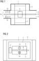
- Fig.1 shows an exemplary embodiment of a current sensor arrangement according to the invention as a schematic elevation.
- a magnetic core 1 made of a soft magnetic material (ferrite) is arranged in a housing 3 made of injection-molded plastic.
- the magnetic core 1 is designed in one piece and is therefore magnetically closed, which achieves a particularly effective shielding effect.
- the magnetic core 1 comprises several parts.
- individual parts of the magnetic core 1 must be closely adjacent to one another.
- a busbar conductor 8 (also called busbar, current bar or busbar in English) is guided in the housing 3, which has a supply conductor 4 and an arrester 5, wherein an insulating spacer 6 is arranged between the supply conductor 4 and the arrester 5.
- the busbar conductor 8 is designed in one piece, i.e. it has a U-shaped loop (not shown). The supply conductor 4 therefore passes into the arrester 5 without interruption.
- the supply conductor 4 as a separate first busbar conductor and the discharge conductor 5 as a separate second busbar conductor, separated from one another.
- the spacer 6 is designed as a part of the housing 3 (e.g. as a projection past which the supply conductor 4 and the conductor 5 are guided) and an insulating effect between the supply conductor 4 and the conductor 5 is achieved due to an air gap between the supply conductor 4 and the conductor 5.
- the busbar conductor 8 is made of copper and is connected to a power supply unit of a motor vehicle (not shown).
- the magnetic core 1 and the busbar conductor 8 are cast into the housing 3.
- the supply conductor 4 and the discharge conductor 5 as well as the spacer 6 are in the area which is Fig.1 shown, arranged parallel to each other and guided through the magnetic core 1, which is designed as a hollow cuboid with an interior 7.
- the supply conductor 4, the conductor 5 and the spacer 6 are arranged in the interior 7 parallel to the magnetic core 1. Between the supply conductor 4 and the conductor 5 is a Fig.3 The distance a shown is 0.5 mm.
- a magnetic field sensor 2 Also provided in the interior space 7 of the magnetic core 1 is a magnetic field sensor 2, known from the prior art and designed as a Hall sensor.
- the magnetic field sensor 2 for example, as a superconducting quantum interference device (SQUID).
- a sensor based on a magneto-optical effect such as a polarimetric sensor, is also conceivable as the magnetic field sensor 2.
- the magnetic field sensor 2 can also be designed as a fluxgate magnetometer known from the prior art or as a Förster probe.
- the magnetic field sensor 2 is, as in Fig.3 shown, between a first side wall 9 of the magnetic core 1 and a first side plane 11 of the feed conductor 4, the conductor 5 and the spacer 6, in the region of the smallest distance d between the busbar conductor 8 and the spacer 6 on the one hand and the magnetic core 1 on the other hand.
- This distance d is 1.5 mm. Since the busbar conductor 8 and the spacer 6 are arranged exactly in the middle with respect to the magnetic core 1, this smallest distance d occurs in the amount of 1.5 mm, as in Fig.3 visible, also between a second side wall 10 of the magnetic core 1 and a second Side plane 12 of the busbar conductor 8 and the spacer 6.
- a first current flow symbolically represented by a first directional arrow 13, runs to the right (with respect to Fig.1 ) through the supply conductor 4.
- a second current flow is symbolically represented by a second directional arrow 14 and runs to the left (with respect to Fig.1 ) through the arrester 5.
- the magnetic field sensor 2 is used to carry out a potential-free measurement of the current intensity of the first current flow and the second current flow in the busbar conductor 8.
- the housing 3 also contains a pyrotechnic isolating switch known from the prior art, which is not shown.
- the isolating switch has a propellant charge, a first ignition contact and a second ignition contact, which, when a defined current intensity (interference or fault current) is exceeded, which is detected by an evaluation unit (not shown) connected to the magnetic field sensor 2 and the isolating switch, triggers the propellant charge by transmitting corresponding ignition signals from this evaluation unit to the first ignition contact and to the second ignition contact and ignites the propellant charge.
- An explosion interrupts an electrical connection (not shown) in the housing 3, whereby an electrical unit (also not shown) connected to the power supply unit via the isolating switch is separated from the power supply unit.
- the current sensor arrangement therefore functions as a fuse.
- the voltage provided by the power supply unit is 48 V. However, according to the invention, other voltage ranges are also conceivable.
- Fig. 2 is a schematic side view of the Fig.1 shown embodiment of a current sensor arrangement according to the invention. Therefore, the same reference numerals as in Fig.1 used.
- a first current flow in a supply conductor 4 is symbolically indicated by a first directional arrow 13, which is drawn from an image plane of Fig. 2 out, shown.
- a second current flow in an arrester 5 is symbolically indicated by a second directional arrow 14, which points into the image plane of Fig. 2 shows in, reveals.
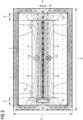
- Fig.3 discloses that embodiment of a current sensor arrangement according to the invention, which is also Fig. 1 and Fig. 2 is shown.
- a busbar conductor 8 which has a supply conductor 4 and a discharge conductor 5, as well as an insulating spacer 6 arranged between them, is guided through the magnetic core 1 arranged in the housing 3 shown, which has a width b of 21 mm and a height h of 12 mm.
- the supply conductor 4, the conductor 5 and the spacer 6 are arranged in an interior space 7 of the magnetic core 1 parallel to one another and parallel to the magnetic core 1. A distance a of 0.5 mm is provided between the supply conductor 4 and the conductor 5.
- a magnetic field sensor 2 known from the prior art. It is arranged between a first side wall 9 of the magnetic core 1 and a first side plane 11 of the busbar conductor 8 and the spacer 6, in the region of the smallest distance d between the busbar conductor 8 and the spacer 6 on the one hand and the magnetic core 1 on the other hand.
- This distance d is 1.5 mm. Since the busbar conductor 8 and the spacer 6 are arranged exactly centrally in relation to the magnetic core 1, this smallest distance d of 1.5 mm also occurs between a second side wall 10 of the magnetic core 1 and a second side plane 12 of the busbar conductor 8 and the spacer 6. However, according to the invention, other, off-center arrangements of the busbar conductor 8 and the spacer 6 are also conceivable.
- a magnetic field or a magnetic flux is formed in the magnetic core 1, in the busbar conductor 8, in the interior 7 and in the magnetic field sensor 2, which is symbolically represented by a first flux line 15 and further flux lines.
- the magnetic field sensor 2 is therefore arranged in the magnetic flux.
- the magnetic field sensor 2 has a measuring range of 0 to 200 mT.
- the measuring range depends on the distance a and dimensions of the magnetic core 1 (for example width b and height h).
- the maximum flux density in the magnetic core 1 is 300 mT and is far below a saturation flux density of the magnetic core 1 of 700 mT. Saturation of the magnetic core 1 is therefore avoided.
- the flux density in the area of the magnetic field sensor 2 is 117 mT (flux density measured by the magnetic field sensor 2).
- the current intensity in the busbar conductor 8 is determined by means of an evaluation unit (not shown) which is connected to the magnetic field sensor 2 via an approximately linear relationship known from the prior art between this flux density and the current intensity in the busbar conductor 8. If this current intensity exceeds a defined threshold value, this is recognized as an error. On this basis, fault currents, which can be short-circuit currents or overcurrents, for example, are detected.
Landscapes
- Physics & Mathematics (AREA)
- General Physics & Mathematics (AREA)
- Measuring Instrument Details And Bridges, And Automatic Balancing Devices (AREA)
- Transformers For Measuring Instruments (AREA)
Description
- Die Erfindung bezieht sich auf eine Stromsensoranordnung mit einem Magnetkern und einem Magnetfeldsensor, die in einem Gehäuse angeordnet sind.
- In der Fahrzeugelektronik, bei 48 V - Systemen (Hybridfahrzeuge) und Systemen höherer Spannung, besteht die Notwendigkeit, Fehlerströme (Kurzschlussströme oder Überströme) zu detektieren und bei einer entsprechenden Detektion gegebenenfalls eine Stromversorgungseinrichtung auszuschalten. Dabei können große Ausschaltströme im Kiloamperebereich fließen. Die Messung dieser Ströme ist daher teuer und entsprechende Messeinrichtungen erfordern ein großes Bauraumbudget.
- Weiterhin sind häufig potentialfreie Messverfahren erforderlich.
- Aus dem Stand der Technik ist beispielsweise die
DE 10 2015 117 651 A1 bekannt, in der eine Sensorbaugruppe für einen Stromsensor offenbart ist. Es ist ein Magnetkern angeordnet, der eine rechteckige Querschnittform mit abgerundeten Ecken oder eine kreisförmige Querschnittform aufweist. Der Magnetkern ist hohl, d.h. es ist ein Innenraum für eine Stromschiene vorgesehen. - Die Sensorbaugruppe weist weiterhin Hallelemente auf, welche in Aufnahmen gelagert sind. Die Aufnahmen sind wiederum in Schlitzen des Magnetkerns angeordnet.
- Weiterhin zeigt die
WO 2011/067132 A1 einen pyrotechnischen Sicherungsschalter für eine Batterie eines Fahrzeugs, der einen Gasraum aufweist, in welchem ein Treibsatz, der elektrische Kontakte aufweist, gezündet werden kann. Ein Aufprall des Fahrzeugs wird mittels einer Crashsensorik detektiert und zwischen den Kontakten wird eine Zündspannung gebildet. Der Treibsatz wird gezündet und explodiert, wodurch eine Stromversorgung unterbrochen wird. - Ferner ist in der
US 2005/0030004 A1 ein Stromsensor dargestellt, welcher einem U-förmigen Leiter zwischengeordnet ist. Der Stromsensor und der U-förmige Leiter sind in einem Gehäuse aus magnetischem Material angeordnet. - Die
US2015/042324A1 offenbart einen Stromsensor in einem Gehäuse, bei welchem Leiter durch rohrförmige Öffnungen in dem Gehäuse sowie durch Ausnehmungen in einem Magnetkern geführt sind. In den Ausnehmungen sind Detektionselemente angeordnet. - Der Erfindung liegt die Aufgabe zugrunde, eine gegenüber dem Stand der Technik weiterentwickelte Stromsensoranordnung anzugeben.
- Erfindungsgemäß wird diese Aufgabe gelöst mit einer Stromsensoranordnung der eingangs genannten Art,
- bei der ein Zuleiter und ein Ableiter vorgesehen sind,
- bei welcher der Zuleiter und der Ableiter mit dem Gehäuse verbunden sind,
- bei der zwischen dem Zuleiter und dem Ableiter ein isolierendes Distanzstück anordenbar ist,
- bei welcher der Magnetkern einen Innenraum aufweist, durch den der Zuleiter und der Ableiter geführt sind,
- bei welcher der Magnetfeldsensor in dem Innenraum des Magnetkerns vorgesehen ist, und
- bei welcher der Zuleiter und der Ableiter in einem definierten Abstand zueinander angeordnet sind.
- Aufgrund des definierten Abstands zwischen dem Zuleiter und dem Ableiter wird eine definierte Abschwächung eines magnetischen Felds in dem Magnetkern bewirkt, ohne dass dafür z.B. eine Spule nötig ist. Dadurch wird eine kompakte und kostengünstige Ausführung der Stromsensoranordnung erzielt. Durch die Abschwächung des magnetischen Felds wird eine Reduktion einer Flussdichte in der Stromsensoranordnung bewirkt. Dadurch ist es möglich, große Ströme bei kleinen Flussdichten in einem Magnetkreis zu messen.
- Es können dadurch weiterhin kostengünstige, weichmagnetische Materialen anstatt spezieller Materialien mit hoher Sättigungsflussdichte für den Magnetkern eingesetzt werden. Darüber hinaus vermeiden kleine magnetische Flussdichten eine remanente Magnetisierung des Magnetkerns, eine Bildung von Remanenzflussdichten und somit Fehler bei der Strommessung.
- Ferner wird dadurch, dass der Zuleiter und der Ableiter durch den Innenraum hindurch geführt sind sowie dadurch, dass der Magnetfeldsensor in dem Innenraum des Magnetkerns angeordnet ist, eine vorteilhafte Schirmung und somit eine hohe Messgenauigkeit (d.h. eine Verringerung von Messfehlern) erzielt. Auf separate Schirmungsmaßnahmen, welche insbesondere im Umfeld von Blechen, Fremdfeldern etc. erforderlich sind, kann verzichtet werden.
- Die kompakte Ausführung der Stromsensoranordnung, bei welcher der Zuleiter und der Ableiter in dem Innenraum des Magnetkerns geführt sind und der Magnetfeldsensor in dem Innenraum angeordnet ist, ermöglicht einerseits eine Vergrößerung von Strommessbereichen sowie andererseits eine Einsetzbarkeit der Stromsensoranordnung auch bei stark begrenzten Bauraumbudgets.
- Es ist günstig, wenn der Magnetfeldsensor zwischen dem Zuleiter und dem Ableiter einerseits und dem Magnetkern andererseits auf jener Seite mit einer Distanz zwischen dem Zuleiter und dem Ableiter einerseits und dem Magnetkern andererseits angeordnet ist.
- Durch diese Maßnahme wird eine gezielte Abschwächung des magnetischen Felds und somit eine vorteilhafte Anpassung von zu erfassenden Messgrößen an den verfügbaren Magnetfeldsensor und an Materialeigenschaften des Magnetkerns erzielt.
- Eine vorteilhafte Ausgestaltung erhält man, wenn der Magnetkern magnetisch geschlossen ist.
- Durch diese Maßnahme wird eine besonders effektive Schirmung erzielt.
- Es ist günstig, wenn der Magnetfeldsensor als Förster-Sonde ausgebildet ist.
- Durch diese Maßnahme wird eine hohe Messgenauigkeit bewirkt.
- Nachfolgend wird die Erfindung anhand von Ausführungsbeispielen näher erläutert.
- Es zeigen beispielhaft:
- Fig. 1:
- Einen schematischen Aufriss einer beispielhaften Ausführungsvariante einer erfindungsgemäßen Stromsensoranordnung,
- Fig. 2:
- Einen schematischen Seitenriss dieser beispielhaften Ausführungsvariante, und
- Fig. 3:
- Eine Ergebnisdarstellung einer Finite Elemente - Simulation dieser beispielhaften Ausführungsvariante, wobei ein magnetischer Fluss gezeigt ist.
-
Fig. 1 zeigt eine beispielhafte Ausführungsvariante einer erfindungsgemäßen Stromsensoranordnung als schematischen Aufriss. - Ein Magnetkern 1 aus einem weichmagnetischen Werkstoff (Ferrit) ist in einem Gehäuse 3 aus Kunststoff-Spritzguss angeordnet. Der Magnetkern 1 ist einteilig und somit magnetisch geschlossen ausgeführt, wodurch eine besonders effektive Schirmungswirkung erzielt wird.
- Erfindungsgemäß ist es jedoch auch denkbar, dass der Magnetkern 1 mehrere Teile umfasst. Um einen magnetischen Schluss und somit eine günstige Schirmungswirkung auch bei einer mehrteiligen Ausführungsvariante des Magnetkerns 1 zu erreichen, müssen einzelne Teile des Magnetkerns 1 dicht aneinander grenzen.
- In dem Gehäuse 3 geführt sind ein Sammelschienenleiter 8 (auch Sammelschiene, Stromschiene oder auf Englisch busbar genannt), der einen Zuleiter 4 und einen Ableiter 5 aufweist, wobei zwischen dem Zuleiter 4 und dem Ableiter 5 ein isolierendes Distanzstück 6 angeordnet ist.
- Der Sammelschienenleiter 8 ist einteilig ausgeführt, d.h. er weist eine nicht dargestellte, U-förmige Schleife auf. Der Zuleiter 4 geht demnach ohne Unterbrechung in den Ableiter 5 über.
- Erfindungsgemäß ist es auch vorstellbar, den Zuleiter 4 als eigenen ersten Sammelschienenleiter und den Ableiter 5 als eigenen zweiten Sammelschienenleiter getrennt voneinander auszuführen.
- Weiterhin ist es auch denkbar, dass das Distanzstück 6 als ein Teil des Gehäuses 3 ausgeführt ist (z.B. als Auskragung, an welcher der Zuleiter 4 und der Ableiter 5 vorbeigeführt sind) und eine isolierende Wirkung zwischen dem Zuleiter 4 und dem Ableiter 5 aufgrund eines Luftspalts zwischen dem Zuleiter 4 und dem Ableiter 5 erreicht wird.
- Der Sammelschienenleiter 8 ist in Kupfer ausgeführt und mit einer nicht dargestellten Spannungsversorgungseinheit eines Kraftfahrzeugs verbunden.
- Der Magnetkern 1 und der Sammelschienenleiter 8 sind mit dem Gehäuse 3 vergossen.
- Der Zuleiter 4 und der Ableiter 5 sowie das Distanzstück 6 sind in jenem Bereich, der in
Fig. 1 gezeigt ist, parallel zueinander angeordnet und durch den Magnetkern 1, welcher als hohler Quader mit einem Innenraum 7 ausgebildet ist, geführt. Der Zuleiter 4, der Ableiter 5 und das Distanzstück 6 sind in dem Innenraum 7 parallel zu dem Magnetkern 1 angeordnet. Zwischen dem Zuleiter 4 und dem Ableiter 5 ist ein inFig. 3 gezeigter Abstand a vorgesehen, welcher 0,5 mm beträgt. - Ebenfalls in dem Innenraum 7 des Magnetkerns 1 vorgesehen ist ein aus dem Stand der Technik bekannter, als Hall-Sensor ausgebildeter Magnetfeldsensor 2.
- Erfindungsgemäß ist es auch vorstellbar, den Magnetfeldsensor 2 beispielsweise als Superconducting Quantum Interference Device (SQUID) auszuführen. Weiterhin ist als Magnetfeldsensor 2 beispielsweise auch ein Sensor denkbar, welcher auf einem magnetooptischen Effekt basiert, wie z.B. ein polarimetrischer Sensor.
- Ferner kann der Magnetfeldsensor 2 auch als aus dem Stand der Technik bekanntes Fluxgate-Magnetometer bzw. als Förster-Sonde ausgebildet sein.
- Der Magnetfeldsensor 2 ist, wie in
Fig. 3 gezeigt, zwischen einer ersten Seitenwand 9 des Magnetkerns 1 und einer ersten Seitenebene 11 des Zuleiters 4, des Ableiters 5 und des Distanzstücks 6, im Bereich der kleinsten Distanz d zwischen dem Sammelschienenleiter 8 und dem Distanzstück 6 einerseits und dem Magnetkern 1 andererseits angeordnet. Diese Distanz d beträgt 1,5 mm. Da der Sammelschienenleiter 8 und das Distanzstück 6 genau mittig in Bezug auf den Magnetkern 1 angeordnet sind, tritt diese kleinste Distanz d im Ausmaß von 1,5 mm, wie inFig. 3 ersichtlich, auch zwischen einer zweiten Seitenwand 10 des Magnetkerns 1 und einer zweiten Seitenebene 12 des Sammelschienenleiters 8 und des Distanzstücks 6 auf. - Durch den Sammelschienenleiter 8 hindurch fließt Strom unterschiedlicher Richtungen und mit einer Stromstärke von 3500 A.
- Ein erster Stromfluss verläuft, symbolisch dargestellt mittels eines ersten Richtungspfeils 13, nach rechts (bezüglich
Fig. 1 ) durch den Zuleiter 4. - Ein zweiter Stromfluss ist mittels eines zweiten Richtungspfeils 14 symbolisch dargestellt und verläuft nach links (bezüglich
Fig. 1 ) durch den Ableiter 5. - Wegen des ersten Stromflusses und des zweiten Stromflusses bildet sich aufgrund bekannter physikalischer Prinzipien ein magnetischer Fluss aus, welcher in
Fig. 3 dargestellt ist. Mittels des Magnetfeldsensors 2 erfolgt eine potentialfreie Messung der Stromstärke des ersten Stromflusses und des zweiten Stromflusses in dem Sammelschienenleiter 8. - In dem Gehäuse 3 ist weiterhin auch ein aus dem Stand der Technik bekannter, pyrotechnischer Trennschalter vorgesehen, der nicht dargestellt ist. Der Trennschalter weist einen Treibsatz, einen ersten Zündkontakt und einen zweiten Zündkontakt auf, welche bei Überschreiten einer definierten Stromstärke (Stör- bzw. Fehlerstrom), welche von einer mit dem Magnetfeldsensor 2 und dem Trennschalter verbundenen, nicht gezeigten Auswerteeinheit detektiert wird, mittels Übertragung entsprechender Zündsignale von dieser Auswerteeinheit an den ersten Zündkontakt und an den zweiten Zündkontakt auslösen und den Treibsatz zünden. Durch eine Explosion wird eine nicht dargestellte elektrische Verbindung in dem Gehäuse 3 unterbrochen, wodurch ein über den Trennschalter mit der Spannungsversorgungseinheit verbundenes, ebenfalls nicht dargestelltes elektrisches Aggregat von der Spannungsversorgungseinheit getrennt wird. Die Stromsensoranordnung fungiert also als Sicherung.
- Die von der Spannungsversorgungseinheit bereitgestellte Spannung beträgt 48 V. Erfindungsgemäß sind jedoch auch andere Spannungsbereiche denkbar.
- In
Fig. 2 ist ein schematischer Seitenriss der inFig. 1 gezeigten Ausführungsvariante einer erfindungsgemäßen Stromsensoranordnung dargestellt. Es werden daher gleiche Bezugszeichen wie inFig. 1 verwendet. - Ein erster Stromfluss in einem Zuleiter 4 ist symbolisch mittels eines ersten Richtungspfeils 13, welcher aus einer Bildebene von
Fig. 2 heraus zeigt, dargestellt. - Ein zweiter Stromfluss in einem Ableiter 5 ist symbolisch mittels eines zweiten Richtungspfeils 14, welcher in die Bildebene von
Fig. 2 hinein zeigt, offenbart. -
Fig. 3 offenbart jene Ausführungsvariante einer erfindungsgemäßen Stromsensoranordnung, die auch inFig. 1 und Fig. 2 dargestellt ist. - Durch einen in einem in
Fig. 1 und Fig. 2 gezeigten Gehäuse 3 angeordneten Magnetkern 1, der eine Breite b von 21 mm und eine Höhe h von 12 mm aufweist, hindurch ist ein Sammelschienenleiter 8, welcher einen Zuleiter 4 sowie einen Ableiter 5 aufweist, sowie ein dazwischen angeordnetes isolierendes Distanzstück 6 geführt. - Der Zuleiter 4, der Ableiter 5 und das Distanzstück 6 sind in einem Innenraum 7 des Magnetkerns 1 parallel zueinander und parallel zu dem Magnetkern 1 angeordnet. Zwischen dem Zuleiter 4 und dem Ableiter 5 ist ein Abstand a vorgesehen, welcher 0,5 mm beträgt.
- Ebenfalls in dem Innenraum 7 des Magnetkerns 1 vorgesehen ist ein aus dem Stand der Technik bekannter Magnetfeldsensor 2. Er ist zwischen einer ersten Seitenwand 9 des Magnetkerns 1 und einer ersten Seitenebene 11 des Sammelschienenleiters 8 und des Distanzstücks 6, im Bereich der kleinsten Distanz d zwischen dem Sammelschienenleiter 8 und dem Distanzstück 6 einerseits und dem Magnetkern 1 andererseits angeordnet.
- Diese Distanz d beträgt 1,5 mm. Da der Sammelschienenleiter 8 und das Distanzstück 6 genau mittig in Bezug auf den Magnetkern 1 angeordnet sind, tritt diese kleinste Distanz d im Ausmaß von 1,5 mm auch zwischen einer zweiten Seitenwand 10 des Magnetkerns 1 und einer zweiten Seitenebene 12 des Sammelschienenleiters 8 und des Distanzstücks 6 auf. Erfindungsgemäß sind jedoch auch andere, außermittige Anordnungen des Sammelschienenleiters 8 und des Distanzstücks 6 denkbar.
- Weiterhin ist es auch denkbar, dass zwischen dem Zuleiter 4 und dem Ableiter 5 anstatt des Distanzstücks 6 ein Luftspalt von definierter Größe vorgesehen ist. Entscheidend ist ein Vorhandensein isolierender Eigenschaften zwischen dem Zuleiter 4 und dem Ableiter 5.
- Durch den Sammelschienenleiter 8 hindurch fließt Strom unterschiedlicher Richtungen (erster Stromfluss in dem Zuleiter 4 mit einem symbolischen ersten Richtungspfeil 13, zweiter Stromfluss in dem Ableiter 5 mit einem symbolischen zweiten Richtungspfeil 14) und mit einer Stromstärke von 3500 A.
- Wegen des ersten Stromflusses und des zweiten Stromflusses ist in dem Magnetkern 1, in dem Sammelschienenleiter 8, in dem Innenraum 7 sowie in dem Magnetfeldsensor 2 ein magnetisches Feld bzw. ein magnetischer Fluss ausgebildet, welches bzw. welcher mittels einer ersten Flusslinie 15 sowie weiteren Flusslinien symbolisch dargestellt ist. Der Magnetfeldsensor 2 ist demnach in dem magnetischen Fluss angeordnet.
- Der Magnetfeldsensor 2 weist einen Messbereich von 0 bis 200 mT auf. Der Messbereich hängt von dem Abstand a und Dimensionen des Magnetkerns 1 (beispielsweise Breite b und Höhe h) ab.
- Aufgrund des Abstands a wird eine Abschwächung des magnetischen Felds in dem Magnetkern 1 bewirkt.
- Durch die Abschwächung des magnetischen Felds wird eine Reduktion einer Flussdichte in der Stromsensoranordnung erzielt.
- Die maximale Flussdichte in dem Magnetkern 1 beträgt 300 mT und liegt weit unter einer Sättigungsflussdichte des Magnetkerns 1 von 700 mT. Eine Sättigung des Magnetkerns 1 wird folglich vermieden.
- Die Flussdichte beträgt im Bereich des Magnetfeldsensors 2 117 mT (mittels des Magnetfeldsensors 2 gemessene Flussdichte). Über einen aus dem Stand der Technik bekannten, annähernd linearen Zusammenhang zwischen dieser Flussdichte und der Stromstärke in dem Sammelschienenleiter 8 wird mittels einer nicht gezeigten Auswerteeinheit, welche mit dem Magnetfeldsensor 2 verbunden ist, die Stromstärke in dem Sammelschienenleiter 8 bestimmt. Überschreitet diese Stromstärke einen definierten Schwellwert, so wird dies als Fehler erkannt. Auf Grundlage dessen werden Fehlerströme, wobei es sich beispielsweise um Kurzschlussströme oder Überströme handeln kann, detektiert.
-
- 1
- Magnetkern
- 2
- Magnetfeldsensor
- 3
- Gehäuse
- 4
- Zuleiter
- 5
- Ableiter
- 6
- Distanzstück
- 7
- Innenraum
- 8
- Sammelschienenleiter
- 9
- Erste Seitenwand
- 10
- Zweite Seitenwand
- 11
- Erste Seitenebene
- 12
- Zweite Seitenebene
- 13
- Erster Richtungspfeil
- 14
- Zweiter Richtungspfeil
- 15
- Erste Flusslinie
- a
- Abstand
- d
- Distanz
- b
- Breite
- h
- Höhe
Claims (6)
- Stromsensoranordnung mit einem Magnetkern und einem Magnetfeldsensor, die in einem Gehäuse angeordnet sind,dadurch gekennzeichnet, dass ein Zuleiter (4) und ein Ableiter (5) angeordnet sind,dass der Zuleiter (4) und der Ableiter (5) mit dem Gehäuse (3) verbunden sind,dass zwischen dem Zuleiter (4) und dem Ableiter (5) ein isolierendes Distanzstück (6) angeordnet ist,dass der Magnetkern (1) einen Innenraum (7) aufweist, wobei zur Erzielung einer vorteilhaften Schirmung und somit einer hohen Messgenauigkeit der Zuleiter (4) und der Ableiter (5) durch den Innenraum (7) geführt sind und der Magnetfeldsensor (2) in dem Innenraum (7) des Magnetkerns (1) angeordnet ist, unddass der Zuleiter (4) und der Ableiter (5) in einem definierten Abstand a zueinander angeordnet sind.
- Stromsensoranordnung nach Anspruch 1, dadurch gekennzeichnet, dass der Magnetfeldsensor (2) zwischen dem Zuleiter (4) und dem Ableiter (5) einerseits und dem Magnetkern (1) andererseits auf jener Seite mit einer Distanz d zwischen dem Zuleiter (4) und dem Ableiter (5) einerseits und dem Magnetkern (1) andererseits angeordnet ist.
- Stromsensoranordnung nach Anspruch 1 oder 2, dadurch gekennzeichnet, dass der Magnetkern (1) magnetisch geschlossen ist.
- Stromsensoranordnung nach einem der Ansprüche 1 bis 3, dadurch gekennzeichnet, dass der Magnetfeldsensor (2) als Hall-Sensor ausgebildet ist.
- Stromsensoranordnung nach einem der Ansprüche 1 bis 3, dadurch gekennzeichnet, dass der Magnetfeldsensor (2) als Förster-Sonde ausgebildet ist.
- Trennschalter mit einer Stromsensoranordnung nach einem der Ansprüche 1 bis 5.
Applications Claiming Priority (2)
| Application Number | Priority Date | Filing Date | Title |
|---|---|---|---|
| ATA50892/2017A AT520624B1 (de) | 2017-10-24 | 2017-10-24 | Stromsensoranordnung |
| PCT/EP2018/079040 WO2019081511A1 (de) | 2017-10-24 | 2018-10-23 | Stromsensoranordnung |
Publications (2)
| Publication Number | Publication Date |
|---|---|
| EP3655784A1 EP3655784A1 (de) | 2020-05-27 |
| EP3655784B1 true EP3655784B1 (de) | 2024-07-31 |
Family
ID=64270807
Family Applications (1)
| Application Number | Title | Priority Date | Filing Date |
|---|---|---|---|
| EP18800497.2A Active EP3655784B1 (de) | 2017-10-24 | 2018-10-23 | Stromsensoranordnung |
Country Status (3)
| Country | Link |
|---|---|
| EP (1) | EP3655784B1 (de) |
| AT (1) | AT520624B1 (de) |
| WO (1) | WO2019081511A1 (de) |
Cited By (1)
| Publication number | Priority date | Publication date | Assignee | Title |
|---|---|---|---|---|
| DE102024209345A1 (de) * | 2024-09-26 | 2026-03-26 | Infineon Technologies Ag | Stromsensorbauteile und Verfahren zu deren Herstellung |
Families Citing this family (1)
| Publication number | Priority date | Publication date | Assignee | Title |
|---|---|---|---|---|
| DE102023211504A1 (de) | 2023-11-20 | 2025-05-22 | Robert Bosch Gesellschaft mit beschränkter Haftung | Sensoranordnung, Schaltungsanordnung und Vorrichtung |
Citations (1)
| Publication number | Priority date | Publication date | Assignee | Title |
|---|---|---|---|---|
| US20150042324A1 (en) * | 2013-08-07 | 2015-02-12 | Aisin Seiki Kabushiki Kaisha | Current sensor |
Family Cites Families (9)
| Publication number | Priority date | Publication date | Assignee | Title |
|---|---|---|---|---|
| US5450000A (en) * | 1994-02-14 | 1995-09-12 | Unity Power Corporation | Using hall device for controlling current in a switchmode circuit |
| DE69920890T2 (de) * | 1999-01-21 | 2005-02-03 | Tdk Corp. | Stromsensor |
| AU2002349497A1 (en) * | 2001-11-26 | 2003-06-10 | Asahi Kasei Electronics Co., Ltd. | Current sensor |
| EP2083277B1 (de) * | 2008-01-25 | 2011-01-05 | Liaisons Electroniques-Mecaniques Lem S.A. | Stromsensor |
| US8760149B2 (en) * | 2010-04-08 | 2014-06-24 | Infineon Technologies Ag | Magnetic field current sensors |
| JP2013015431A (ja) * | 2011-07-05 | 2013-01-24 | Sumitomo Wiring Syst Ltd | 電流検出装置 |
| US9001476B2 (en) * | 2013-03-15 | 2015-04-07 | Rockwell Automation Technologies, Inc. | Multimotor variable frequency overload |
| DE102015117651A1 (de) * | 2015-10-16 | 2017-04-20 | Harting Electric Gmbh & Co. Kg | Sensorbaugruppe für einen Stromsensor, Stromsensor mit einer solchen Sensorbaugruppe, Halter für einen solchen Stromsensor sowie Verfahren zur Montage eines Stromsensors |
| CN106653999A (zh) * | 2016-12-22 | 2017-05-10 | 上海南麟电子股份有限公司 | 一种单芯片霍尔电流传感器及其制备方法 |
-
2017
- 2017-10-24 AT ATA50892/2017A patent/AT520624B1/de not_active IP Right Cessation
-
2018
- 2018-10-23 EP EP18800497.2A patent/EP3655784B1/de active Active
- 2018-10-23 WO PCT/EP2018/079040 patent/WO2019081511A1/de not_active Ceased
Patent Citations (1)
| Publication number | Priority date | Publication date | Assignee | Title |
|---|---|---|---|---|
| US20150042324A1 (en) * | 2013-08-07 | 2015-02-12 | Aisin Seiki Kabushiki Kaisha | Current sensor |
Cited By (1)
| Publication number | Priority date | Publication date | Assignee | Title |
|---|---|---|---|---|
| DE102024209345A1 (de) * | 2024-09-26 | 2026-03-26 | Infineon Technologies Ag | Stromsensorbauteile und Verfahren zu deren Herstellung |
Also Published As
| Publication number | Publication date |
|---|---|
| AT520624B1 (de) | 2024-02-15 |
| EP3655784A1 (de) | 2020-05-27 |
| WO2019081511A1 (de) | 2019-05-02 |
| AT520624A1 (de) | 2019-05-15 |
Similar Documents
| Publication | Publication Date | Title |
|---|---|---|
| DE10049071B4 (de) | Sicherungsvorrichtung für einen Stromkreis insbesondere in Kraftfahrzeugen | |
| DE102018213522C5 (de) | Schmelzsicherung, Sicherungskörper, System und Verfahren | |
| EP3429885B1 (de) | Dc-überstromschutzvorrichtung | |
| DE102018120984B4 (de) | Schaltvorrichtung | |
| EP3983812B1 (de) | Sensor, schutzschalter, ladekabel und ladestation | |
| EP2587513A1 (de) | Installationsschaltgerät mit einer Stromsensoreinheit | |
| DE102015218290A1 (de) | Vorrichtung für Hoch-/Mittel-/Niederspannungsstrommessung | |
| AT520624B1 (de) | Stromsensoranordnung | |
| DE102017127888B4 (de) | Messeinrichtung zur Verwendung in einem elektrischen Schaltgerät | |
| DE102021125555A1 (de) | Sicherungsvorrichtung für Hochvoltanwendungen | |
| DE202019001746U1 (de) | Kompakt-Schutzschaltgerät | |
| EP3977142B1 (de) | Anordnung zum ermitteln eines durch eine stromschiene fliessenden stroms | |
| DE102018111308B3 (de) | Vorrichtung zur Erfassung elektrischer Ströme an oder in der Nähe elektrischer Leiter | |
| WO2017097446A1 (de) | Leistungsschütz und verfahren zur funktionsprüfung eines leistungsschützes | |
| EP4252266B1 (de) | Isolierstoffgehäuse und kompakt-leitungsschutzschalter | |
| EP4258310A1 (de) | Gehäusemodul, isolierstoffgehäuse und schutzschaltgerät | |
| DE102024106555B3 (de) | Schaltvorrichtung und Betriebsvorrichtung mit einer Schaltvorrichtung | |
| EP3433871B1 (de) | Vorrichtung zur messung eines zustands eines elektrischen schalters, elektrischer schalter und verfahren zur messung eines zustands eines elektrischen schalters | |
| EP2839497B1 (de) | Überstromschutzeinrichtung | |
| DE202020102365U1 (de) | Messvorrichtungsgehäuse, Messvorrichtung und Sicherungsanordnung | |
| EP2116855B1 (de) | Strommesseinrichtung | |
| DE102014226221A1 (de) | Niederspannungs-Schutzschaltgerät und Anordnung zur Überwachung eines Stromkreises in einem Niederspannungsnetz | |
| DE102018219692A1 (de) | Schutzschaltgerät für einen Niederspannungsstromkreis zur Erkennung von seriellen Fehlerlichtbögen | |
| DE102024004486A1 (de) | Schaltvorrichtung und Betriebsvorrichtung mit einer Schaltvorrichtung | |
| DE102022206195A1 (de) | Niederspannungs-Schutzschaltgerät |
Legal Events
| Date | Code | Title | Description |
|---|---|---|---|
| STAA | Information on the status of an ep patent application or granted ep patent |
Free format text: STATUS: UNKNOWN |
|
| STAA | Information on the status of an ep patent application or granted ep patent |
Free format text: STATUS: THE INTERNATIONAL PUBLICATION HAS BEEN MADE |
|
| PUAI | Public reference made under article 153(3) epc to a published international application that has entered the european phase |
Free format text: ORIGINAL CODE: 0009012 |
|
| STAA | Information on the status of an ep patent application or granted ep patent |
Free format text: STATUS: REQUEST FOR EXAMINATION WAS MADE |
|
| 17P | Request for examination filed |
Effective date: 20200219 |
|
| AK | Designated contracting states |
Kind code of ref document: A1 Designated state(s): AL AT BE BG CH CY CZ DE DK EE ES FI FR GB GR HR HU IE IS IT LI LT LU LV MC MK MT NL NO PL PT RO RS SE SI SK SM TR |
|
| AX | Request for extension of the european patent |
Extension state: BA ME |
|
| DAV | Request for validation of the european patent (deleted) | ||
| DAX | Request for extension of the european patent (deleted) | ||
| STAA | Information on the status of an ep patent application or granted ep patent |
Free format text: STATUS: EXAMINATION IS IN PROGRESS |
|
| 17Q | First examination report despatched |
Effective date: 20221114 |
|
| GRAP | Despatch of communication of intention to grant a patent |
Free format text: ORIGINAL CODE: EPIDOSNIGR1 |
|
| STAA | Information on the status of an ep patent application or granted ep patent |
Free format text: STATUS: GRANT OF PATENT IS INTENDED |
|
| INTG | Intention to grant announced |
Effective date: 20240322 |
|
| GRAS | Grant fee paid |
Free format text: ORIGINAL CODE: EPIDOSNIGR3 |
|
| GRAA | (expected) grant |
Free format text: ORIGINAL CODE: 0009210 |
|
| STAA | Information on the status of an ep patent application or granted ep patent |
Free format text: STATUS: THE PATENT HAS BEEN GRANTED |
|
| AK | Designated contracting states |
Kind code of ref document: B1 Designated state(s): AL AT BE BG CH CY CZ DE DK EE ES FI FR GB GR HR HU IE IS IT LI LT LU LV MC MK MT NL NO PL PT RO RS SE SI SK SM TR |
|
| REG | Reference to a national code |
Ref country code: CH Ref legal event code: EP Ref country code: GB Ref legal event code: FG4D Free format text: NOT ENGLISH |
|
| REG | Reference to a national code |
Ref country code: DE Ref legal event code: R096 Ref document number: 502018014957 Country of ref document: DE |
|
| REG | Reference to a national code |
Ref country code: IE Ref legal event code: FG4D Free format text: LANGUAGE OF EP DOCUMENT: GERMAN |
|
| REG | Reference to a national code |
Ref country code: LT Ref legal event code: MG9D |
|
| REG | Reference to a national code |
Ref country code: NL Ref legal event code: MP Effective date: 20240731 |
|
| PG25 | Lapsed in a contracting state [announced via postgrant information from national office to epo] |
Ref country code: PT Free format text: LAPSE BECAUSE OF FAILURE TO SUBMIT A TRANSLATION OF THE DESCRIPTION OR TO PAY THE FEE WITHIN THE PRESCRIBED TIME-LIMIT Effective date: 20241202 |
|
| PG25 | Lapsed in a contracting state [announced via postgrant information from national office to epo] |
Ref country code: PT Free format text: LAPSE BECAUSE OF FAILURE TO SUBMIT A TRANSLATION OF THE DESCRIPTION OR TO PAY THE FEE WITHIN THE PRESCRIBED TIME-LIMIT Effective date: 20241202 |
|
| PG25 | Lapsed in a contracting state [announced via postgrant information from national office to epo] |
Ref country code: NO Free format text: LAPSE BECAUSE OF FAILURE TO SUBMIT A TRANSLATION OF THE DESCRIPTION OR TO PAY THE FEE WITHIN THE PRESCRIBED TIME-LIMIT Effective date: 20241031 |
|
| PG25 | Lapsed in a contracting state [announced via postgrant information from national office to epo] |
Ref country code: FI Free format text: LAPSE BECAUSE OF FAILURE TO SUBMIT A TRANSLATION OF THE DESCRIPTION OR TO PAY THE FEE WITHIN THE PRESCRIBED TIME-LIMIT Effective date: 20240731 Ref country code: NL Free format text: LAPSE BECAUSE OF FAILURE TO SUBMIT A TRANSLATION OF THE DESCRIPTION OR TO PAY THE FEE WITHIN THE PRESCRIBED TIME-LIMIT Effective date: 20240731 Ref country code: GR Free format text: LAPSE BECAUSE OF FAILURE TO SUBMIT A TRANSLATION OF THE DESCRIPTION OR TO PAY THE FEE WITHIN THE PRESCRIBED TIME-LIMIT Effective date: 20241101 Ref country code: PL Free format text: LAPSE BECAUSE OF FAILURE TO SUBMIT A TRANSLATION OF THE DESCRIPTION OR TO PAY THE FEE WITHIN THE PRESCRIBED TIME-LIMIT Effective date: 20240731 |
|
| PG25 | Lapsed in a contracting state [announced via postgrant information from national office to epo] |
Ref country code: BG Free format text: LAPSE BECAUSE OF FAILURE TO SUBMIT A TRANSLATION OF THE DESCRIPTION OR TO PAY THE FEE WITHIN THE PRESCRIBED TIME-LIMIT Effective date: 20240731 |
|
| PG25 | Lapsed in a contracting state [announced via postgrant information from national office to epo] |
Ref country code: LV Free format text: LAPSE BECAUSE OF FAILURE TO SUBMIT A TRANSLATION OF THE DESCRIPTION OR TO PAY THE FEE WITHIN THE PRESCRIBED TIME-LIMIT Effective date: 20240731 |
|
| PG25 | Lapsed in a contracting state [announced via postgrant information from national office to epo] |
Ref country code: IS Free format text: LAPSE BECAUSE OF FAILURE TO SUBMIT A TRANSLATION OF THE DESCRIPTION OR TO PAY THE FEE WITHIN THE PRESCRIBED TIME-LIMIT Effective date: 20241130 |
|
| PG25 | Lapsed in a contracting state [announced via postgrant information from national office to epo] |
Ref country code: HR Free format text: LAPSE BECAUSE OF FAILURE TO SUBMIT A TRANSLATION OF THE DESCRIPTION OR TO PAY THE FEE WITHIN THE PRESCRIBED TIME-LIMIT Effective date: 20240731 |
|
| PG25 | Lapsed in a contracting state [announced via postgrant information from national office to epo] |
Ref country code: RS Free format text: LAPSE BECAUSE OF FAILURE TO SUBMIT A TRANSLATION OF THE DESCRIPTION OR TO PAY THE FEE WITHIN THE PRESCRIBED TIME-LIMIT Effective date: 20241031 Ref country code: ES Free format text: LAPSE BECAUSE OF FAILURE TO SUBMIT A TRANSLATION OF THE DESCRIPTION OR TO PAY THE FEE WITHIN THE PRESCRIBED TIME-LIMIT Effective date: 20240731 |
|
| PG25 | Lapsed in a contracting state [announced via postgrant information from national office to epo] |
Ref country code: RS Free format text: LAPSE BECAUSE OF FAILURE TO SUBMIT A TRANSLATION OF THE DESCRIPTION OR TO PAY THE FEE WITHIN THE PRESCRIBED TIME-LIMIT Effective date: 20241031 Ref country code: PL Free format text: LAPSE BECAUSE OF FAILURE TO SUBMIT A TRANSLATION OF THE DESCRIPTION OR TO PAY THE FEE WITHIN THE PRESCRIBED TIME-LIMIT Effective date: 20240731 Ref country code: NO Free format text: LAPSE BECAUSE OF FAILURE TO SUBMIT A TRANSLATION OF THE DESCRIPTION OR TO PAY THE FEE WITHIN THE PRESCRIBED TIME-LIMIT Effective date: 20241031 Ref country code: NL Free format text: LAPSE BECAUSE OF FAILURE TO SUBMIT A TRANSLATION OF THE DESCRIPTION OR TO PAY THE FEE WITHIN THE PRESCRIBED TIME-LIMIT Effective date: 20240731 Ref country code: LV Free format text: LAPSE BECAUSE OF FAILURE TO SUBMIT A TRANSLATION OF THE DESCRIPTION OR TO PAY THE FEE WITHIN THE PRESCRIBED TIME-LIMIT Effective date: 20240731 Ref country code: IS Free format text: LAPSE BECAUSE OF FAILURE TO SUBMIT A TRANSLATION OF THE DESCRIPTION OR TO PAY THE FEE WITHIN THE PRESCRIBED TIME-LIMIT Effective date: 20241130 Ref country code: HR Free format text: LAPSE BECAUSE OF FAILURE TO SUBMIT A TRANSLATION OF THE DESCRIPTION OR TO PAY THE FEE WITHIN THE PRESCRIBED TIME-LIMIT Effective date: 20240731 Ref country code: GR Free format text: LAPSE BECAUSE OF FAILURE TO SUBMIT A TRANSLATION OF THE DESCRIPTION OR TO PAY THE FEE WITHIN THE PRESCRIBED TIME-LIMIT Effective date: 20241101 Ref country code: FI Free format text: LAPSE BECAUSE OF FAILURE TO SUBMIT A TRANSLATION OF THE DESCRIPTION OR TO PAY THE FEE WITHIN THE PRESCRIBED TIME-LIMIT Effective date: 20240731 Ref country code: ES Free format text: LAPSE BECAUSE OF FAILURE TO SUBMIT A TRANSLATION OF THE DESCRIPTION OR TO PAY THE FEE WITHIN THE PRESCRIBED TIME-LIMIT Effective date: 20240731 Ref country code: BG Free format text: LAPSE BECAUSE OF FAILURE TO SUBMIT A TRANSLATION OF THE DESCRIPTION OR TO PAY THE FEE WITHIN THE PRESCRIBED TIME-LIMIT Effective date: 20240731 |
|
| PG25 | Lapsed in a contracting state [announced via postgrant information from national office to epo] |
Ref country code: RO Free format text: LAPSE BECAUSE OF FAILURE TO SUBMIT A TRANSLATION OF THE DESCRIPTION OR TO PAY THE FEE WITHIN THE PRESCRIBED TIME-LIMIT Effective date: 20240731 Ref country code: DK Free format text: LAPSE BECAUSE OF FAILURE TO SUBMIT A TRANSLATION OF THE DESCRIPTION OR TO PAY THE FEE WITHIN THE PRESCRIBED TIME-LIMIT Effective date: 20240731 Ref country code: SM Free format text: LAPSE BECAUSE OF FAILURE TO SUBMIT A TRANSLATION OF THE DESCRIPTION OR TO PAY THE FEE WITHIN THE PRESCRIBED TIME-LIMIT Effective date: 20240731 |
|
| RAP2 | Party data changed (patent owner data changed or rights of a patent transferred) |
Owner name: MELECS EWS GMBH Owner name: ASTOTEC AUTOMOTIVE GMBH |
|
| PG25 | Lapsed in a contracting state [announced via postgrant information from national office to epo] |
Ref country code: EE Free format text: LAPSE BECAUSE OF FAILURE TO SUBMIT A TRANSLATION OF THE DESCRIPTION OR TO PAY THE FEE WITHIN THE PRESCRIBED TIME-LIMIT Effective date: 20240731 |
|
| PG25 | Lapsed in a contracting state [announced via postgrant information from national office to epo] |
Ref country code: CZ Free format text: LAPSE BECAUSE OF FAILURE TO SUBMIT A TRANSLATION OF THE DESCRIPTION OR TO PAY THE FEE WITHIN THE PRESCRIBED TIME-LIMIT Effective date: 20240731 |
|
| PG25 | Lapsed in a contracting state [announced via postgrant information from national office to epo] |
Ref country code: IT Free format text: LAPSE BECAUSE OF FAILURE TO SUBMIT A TRANSLATION OF THE DESCRIPTION OR TO PAY THE FEE WITHIN THE PRESCRIBED TIME-LIMIT Effective date: 20240731 Ref country code: SK Free format text: LAPSE BECAUSE OF FAILURE TO SUBMIT A TRANSLATION OF THE DESCRIPTION OR TO PAY THE FEE WITHIN THE PRESCRIBED TIME-LIMIT Effective date: 20240731 |
|
| REG | Reference to a national code |
Ref country code: DE Ref legal event code: R119 Ref document number: 502018014957 Country of ref document: DE |
|
| REG | Reference to a national code |
Ref country code: CH Ref legal event code: PL |
|
| PLBE | No opposition filed within time limit |
Free format text: ORIGINAL CODE: 0009261 |
|
| STAA | Information on the status of an ep patent application or granted ep patent |
Free format text: STATUS: NO OPPOSITION FILED WITHIN TIME LIMIT |
|
| GBPC | Gb: european patent ceased through non-payment of renewal fee |
Effective date: 20241031 |
|
| PG25 | Lapsed in a contracting state [announced via postgrant information from national office to epo] |
Ref country code: MC Free format text: LAPSE BECAUSE OF FAILURE TO SUBMIT A TRANSLATION OF THE DESCRIPTION OR TO PAY THE FEE WITHIN THE PRESCRIBED TIME-LIMIT Effective date: 20240731 |
|
| 26N | No opposition filed |
Effective date: 20250501 |
|
| PG25 | Lapsed in a contracting state [announced via postgrant information from national office to epo] |
Ref country code: DE Free format text: LAPSE BECAUSE OF NON-PAYMENT OF DUE FEES Effective date: 20250501 |
|
| PG25 | Lapsed in a contracting state [announced via postgrant information from national office to epo] |
Ref country code: GB Free format text: LAPSE BECAUSE OF NON-PAYMENT OF DUE FEES Effective date: 20241031 |
|
| PG25 | Lapsed in a contracting state [announced via postgrant information from national office to epo] |
Ref country code: LU Free format text: LAPSE BECAUSE OF NON-PAYMENT OF DUE FEES Effective date: 20241023 Ref country code: BE Free format text: LAPSE BECAUSE OF NON-PAYMENT OF DUE FEES Effective date: 20241031 |
|
| PG25 | Lapsed in a contracting state [announced via postgrant information from national office to epo] |
Ref country code: FR Free format text: LAPSE BECAUSE OF NON-PAYMENT OF DUE FEES Effective date: 20241031 |
|
| PG25 | Lapsed in a contracting state [announced via postgrant information from national office to epo] |
Ref country code: CH Free format text: LAPSE BECAUSE OF NON-PAYMENT OF DUE FEES Effective date: 20241031 |
|
| REG | Reference to a national code |
Ref country code: BE Ref legal event code: MM Effective date: 20241031 |
|
| PG25 | Lapsed in a contracting state [announced via postgrant information from national office to epo] |
Ref country code: SE Free format text: LAPSE BECAUSE OF FAILURE TO SUBMIT A TRANSLATION OF THE DESCRIPTION OR TO PAY THE FEE WITHIN THE PRESCRIBED TIME-LIMIT Effective date: 20240731 |
|
| REG | Reference to a national code |
Ref country code: AT Ref legal event code: PC Ref document number: 1708952 Country of ref document: AT Kind code of ref document: T Owner name: ASTOTEC AUTOMOTIVE GMBH, AT Effective date: 20250724 Ref country code: AT Ref legal event code: PC Ref document number: 1708952 Country of ref document: AT Kind code of ref document: T Owner name: MELECS EWS GMBH, AT Effective date: 20250724 |
|
| PG25 | Lapsed in a contracting state [announced via postgrant information from national office to epo] |
Ref country code: IE Free format text: LAPSE BECAUSE OF NON-PAYMENT OF DUE FEES Effective date: 20241023 |
|
| PGFP | Annual fee paid to national office [announced via postgrant information from national office to epo] |
Ref country code: AT Payment date: 20250905 Year of fee payment: 8 |
|
| PG25 | Lapsed in a contracting state [announced via postgrant information from national office to epo] |
Ref country code: CY Free format text: LAPSE BECAUSE OF FAILURE TO SUBMIT A TRANSLATION OF THE DESCRIPTION OR TO PAY THE FEE WITHIN THE PRESCRIBED TIME-LIMIT; INVALID AB INITIO Effective date: 20181023 |
|
| PG25 | Lapsed in a contracting state [announced via postgrant information from national office to epo] |
Ref country code: HU Free format text: LAPSE BECAUSE OF FAILURE TO SUBMIT A TRANSLATION OF THE DESCRIPTION OR TO PAY THE FEE WITHIN THE PRESCRIBED TIME-LIMIT; INVALID AB INITIO Effective date: 20181023 |