EP3655656B1 - Verdrängungspumpe mit rotierender membran - Google Patents
Verdrängungspumpe mit rotierender membran Download PDFInfo
- Publication number
- EP3655656B1 EP3655656B1 EP18745673.6A EP18745673A EP3655656B1 EP 3655656 B1 EP3655656 B1 EP 3655656B1 EP 18745673 A EP18745673 A EP 18745673A EP 3655656 B1 EP3655656 B1 EP 3655656B1
- Authority
- EP
- European Patent Office
- Prior art keywords
- diaphragm
- housing
- chamber
- bearing
- annular
- Prior art date
- Legal status (The legal status is an assumption and is not a legal conclusion. Google has not performed a legal analysis and makes no representation as to the accuracy of the status listed.)
- Active
Links
- 238000006073 displacement reaction Methods 0.000 title description 2
- 238000005192 partition Methods 0.000 claims description 14
- 230000002787 reinforcement Effects 0.000 claims description 9
- 239000012530 fluid Substances 0.000 claims description 7
- 230000003014 reinforcing effect Effects 0.000 description 11
- 239000000463 material Substances 0.000 description 10
- 238000001125 extrusion Methods 0.000 description 2
- 238000000465 moulding Methods 0.000 description 2
- 230000003068 static effect Effects 0.000 description 2
- 230000009471 action Effects 0.000 description 1
- 230000008901 benefit Effects 0.000 description 1
- 230000005540 biological transmission Effects 0.000 description 1
- 238000004891 communication Methods 0.000 description 1
- 230000008878 coupling Effects 0.000 description 1
- 238000010168 coupling process Methods 0.000 description 1
- 238000005859 coupling reaction Methods 0.000 description 1
- 230000032798 delamination Effects 0.000 description 1
- 230000000694 effects Effects 0.000 description 1
- 239000007788 liquid Substances 0.000 description 1
- 238000000034 method Methods 0.000 description 1
- 238000012986 modification Methods 0.000 description 1
- 230000004048 modification Effects 0.000 description 1
- 230000002572 peristaltic effect Effects 0.000 description 1
- 230000008569 process Effects 0.000 description 1
- 230000009467 reduction Effects 0.000 description 1
- 238000005096 rolling process Methods 0.000 description 1
- 238000007789 sealing Methods 0.000 description 1
- XLYOFNOQVPJJNP-UHFFFAOYSA-N water Substances O XLYOFNOQVPJJNP-UHFFFAOYSA-N 0.000 description 1
Images

Classifications
-
- F—MECHANICAL ENGINEERING; LIGHTING; HEATING; WEAPONS; BLASTING
- F04—POSITIVE - DISPLACEMENT MACHINES FOR LIQUIDS; PUMPS FOR LIQUIDS OR ELASTIC FLUIDS
- F04C—ROTARY-PISTON, OR OSCILLATING-PISTON, POSITIVE-DISPLACEMENT MACHINES FOR LIQUIDS; ROTARY-PISTON, OR OSCILLATING-PISTON, POSITIVE-DISPLACEMENT PUMPS
- F04C5/00—Rotary-piston machines or pumps with the working-chamber walls at least partly resiliently deformable
-
- F—MECHANICAL ENGINEERING; LIGHTING; HEATING; WEAPONS; BLASTING
- F04—POSITIVE - DISPLACEMENT MACHINES FOR LIQUIDS; PUMPS FOR LIQUIDS OR ELASTIC FLUIDS
- F04B—POSITIVE-DISPLACEMENT MACHINES FOR LIQUIDS; PUMPS
- F04B43/00—Machines, pumps, or pumping installations having flexible working members
- F04B43/0009—Special features
- F04B43/0054—Special features particularities of the flexible members
- F04B43/0072—Special features particularities of the flexible members of tubular flexible members
-
- F—MECHANICAL ENGINEERING; LIGHTING; HEATING; WEAPONS; BLASTING
- F04—POSITIVE - DISPLACEMENT MACHINES FOR LIQUIDS; PUMPS FOR LIQUIDS OR ELASTIC FLUIDS
- F04B—POSITIVE-DISPLACEMENT MACHINES FOR LIQUIDS; PUMPS
- F04B43/00—Machines, pumps, or pumping installations having flexible working members
- F04B43/12—Machines, pumps, or pumping installations having flexible working members having peristaltic action
- F04B43/14—Machines, pumps, or pumping installations having flexible working members having peristaltic action having plate-like flexible members
-
- F—MECHANICAL ENGINEERING; LIGHTING; HEATING; WEAPONS; BLASTING
- F04—POSITIVE - DISPLACEMENT MACHINES FOR LIQUIDS; PUMPS FOR LIQUIDS OR ELASTIC FLUIDS
- F04C—ROTARY-PISTON, OR OSCILLATING-PISTON, POSITIVE-DISPLACEMENT MACHINES FOR LIQUIDS; ROTARY-PISTON, OR OSCILLATING-PISTON, POSITIVE-DISPLACEMENT PUMPS
- F04C2/00—Rotary-piston machines or pumps
- F04C2/02—Rotary-piston machines or pumps of arcuate-engagement type, i.e. with circular translatory movement of co-operating members, each member having the same number of teeth or tooth-equivalents
- F04C2/04—Rotary-piston machines or pumps of arcuate-engagement type, i.e. with circular translatory movement of co-operating members, each member having the same number of teeth or tooth-equivalents of internal axis type
Definitions
- the present invention relates to a rotary diaphragm positive displacement pump.
- Such a rotary pump comprises a housing defining an annular chamber with inlet and outlet ports spaced apart around the chamber, a flexible annular diaphragm forming one side of the chamber spaced opposite an annular wall of the housing, the diaphragm being sealed at its edge to the housing, a partition extending across the chamber from a location between the inlet and outlet ports to the diaphragm; wherein the diaphragm is configured to be pressed progressively against the opposite wall of the housing to force fluid drawn in at the inlet port on one side of the partition around the chamber and to expel it at the outlet port at the other side of the partition.
- the pump has been commercially successful for application such as medical analysis and water dispensing. All of these applications are at a relatively low pressure (typically below 200kPa but more normally below 100kPa). However, at higher pressures, the current design of pump has a more limited life span.
- the present invention is directed to modified version of the pump to allow it to operate more reliable at higher pressures over a longer period of time.
- such a rotary pump is characterised by the characterising features of claim 1.
- the present invention provides an advantage that the annular caps cannot be inserted so far into housing that they overly compress the diaphragm material. Further, both of the end caps can only be inserted to a limited degree and both can be inserted to the same degree. This provides for a more reliable assembly process ensuring alignment between all of the components and reliably forming the seal between the diaphragm and the housing.
- the second end is formed with a groove at the radially outermost portion into which an inner part of the reinforcement ring can move in use. This allows the pump to accommodate a larger reinforcement ring thereby improving the robustness of the pump and providing an enhanced contact between the bearing and reinforcement ring.
- the axial spacing is preferably no more than 0.4 mm and more preferably no more than 0.25 mm.
- the bearing may be a plain bearing or bushing. Alternatively, it may be a rolling element bearing such as ball bearing.
- the configuration of the rotary pump is preferably such that the diaphragm does not rotate relative to the housing.
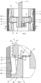
- a tubular part of a rigid housing 1 has an annular groove 2 running around the inner surface, which acts as the pump chamber.
- a flexible diaphragm 3 lies inside the wall of the housing leaving the groove free to contain the pumped fluid.
- a rigid reinforcing ring 4 is moulded into the diaphragm and this ring is at all times in intimate contact with an outer surface of a bearing 5 mounted via an eccentric coupling 6 to a shaft 7 which extends through and is mounted in the housing in bearings (not shown).
- the shaft 7 is mounted concentrically with the annular groove but eccentrically with regard to the axis 8 of the housing 1 and is powered by a motor (not shown). If the reinforcing ring were not present, the diaphragm would stretch and the performance would be reduced in a similar way to that experienced with peristaltic pumps, when the tubing collapses under vacuum.
- the bearing 5, reinforcing ring 4 and central portion of the diaphragm 3 all orbit together inside the housing.
- the two ends of the diaphragm 3 are clamped to the housing 1 by end caps 9, providing an effective and static seal to atmosphere.
- line contact 10 exists between the diaphragm and the groove providing an abutment which pushes the fluid along towards the outlet port 11 and simultaneously draws fluid in through the inlet port 12.
- the pump thus provides pressure and suction cycles at the output and intake respectively which are symmetrical and which vary sinusoidally. Since the diaphragm does not rotate relative to the housing, there is minimal sliding action between them and therefore almost no wear.
- FIG. 1 it can be seen that another feature of the diaphragm moulding is an elastic partition 13 which prevents communication between the outlet 11 and inlet 12 ports. This is positioned between downwardly depending walls 14, 15 which are part of the housing Since the partition is elastic, it accommodates the reciprocating movement of the diaphragm whilst maintaining a static pressure seal between both ports and atmosphere. In this way, all compliant sealing functions required by the pump are provided by the diaphragm moulding and since none of these are sliding seals, they are not subject to significant wear.
- the end caps 9 are best shown in Fig 4 . These have a first end 20 at the outermost face of the end cap and a second end 21 at the opposite innermost face. At the first end 20 is a radially outwardly extending flange 22 which, clamps the diaphragm 3 to the housing 1 with the cooperation of an annular flange 23 in the housing 1. The flange 22 is then fixed to the housing 1 to hold it in place.
- the end cap 9 has a tapered outer face 24 tapering inwardly away from the first end 20. This outer face 24 supports the diaphragm 3 when the diaphragm is in its radially innermost position as shown on the right hand side of Fig 3 .
- annular projection 25 At the radially innermost portion of the second end 21 is an annular projection 25.
- the presence of this projection 25 forms a recess 26 which provides a step reduction in the outer diameter of the end cap 9 in the region adjacent to the second end 21.
- the second end 21 is spaced from the bearing 5 by a very small amount creating a first axial gap 27, in this case less than 0.4 mm and preferably 0.25 mm.
- a second axial gap 28 is present between the recess 26 and the reinforcing ring 4. Again, this is less than 0.4 mm and preferably 0.25 mm.
- the end cap 9 is located by engagement with the flange 22 against the flexible diaphragm 3.
- the flange 22 cannot over compress the diaphragm 3 otherwise the end cap 9 will abut against the reinforcing ring 4 and bearing 5. This ensures that the end cap 9 at either end of the assembly can be inserted consistently as both end caps will compress the diaphragm 3 to the same limited amount.
- the small nature of the second gap 28 also ensures that there is only a very small region of the compressible diaphragm 3 which remains unsupported as the diaphragm 3 is pressed against the end cap 9 (as shown in the right hand side of Fig 3 ). In this position, the opposite outer face of the diaphragm is receiving the full pressure within the pump chamber and this would tend it extrude the diaphragm material in any unsupported region on the opposite side.
- the very small nature of this gap 28 significantly limits the potential for extrusion of the diaphragm 3 even when the pressure in the pump chamber is increased.
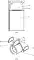
- the reinforcement ring 4 has a modified shape as best shown in Figs. 3 and 4 .
- This comprises an embedded portion 30 forming the radially outermost portion of ring 4 and a support portion 31 forming the radially innermost portion of the ring 4.
- the embedded portion 30 has a crenulated configuration in this case consisting of four annular ridges which, in cross section, have a curved configuration which is devoid of sharp corners. This is to avoid any stress concentrations in the ring 4. These crenulations are designed to provide a large surface area within a relatively limited axial region.
- the diaphragm 3 is formed as an over mould on the ring 4 and the presence of the crenulations maximises the surface area for bonding between the two.
- the relatively large number of rings 32 combined with their generally curved cross sections effectively spreads the load transmission between the two components thereby avoiding delamination of the two components even under relatively high loads.
- the support portion 31 of the ring 4 extends axially beyond the crenulations 32 forming diaphragm support portions 34. These have a radially outwardly facing surface 35 which directly faces an inner face of the diaphragm 3.
- the diaphragm 3 is not bonded to the face 35. However, in the position in which the diaphragm 3 is furthest from the housing 1, the diaphragm is supported in this region by the face 35.
- This feature provides support for the diaphragm at a time when it is under a relatively high inward pressure from the pressure within the pump chamber. As with the gap 28 mentioned above, this support prevents extrusion of the diaphragm material in this stressed position.
- the outer face of the diaphragm 3 is provided with a trough 40 extended axially across a substantial portion of the diaphragm in the vicinity of the outlet.
- a similar trough 41 is provided at the inlet.
- the trough 40 in each case has a first edge 42 adjacent to the partition 13 and a second edge 43 opposite to the first edge.
- the troughs 40, 41 are aligned with a respective outlet duct 44 and inlet duct 45 which lead to the outlet port 11 and from the inlet port 12 respectively.
- troughs 40, 41 In the absence of these troughs 40, 41 when the diaphragm 3 is in the uppermost position, it is possible that while under high pressure, the diaphragm material will extrude into the port to a limited extent thereby causing damage to the diaphragm over time.
- the presence of the troughs 40, 41 reduces or eliminates this effect.
- trough terminates at edge 43 which is adjacent to the edge of duct 44 so that the full thickness of the diaphragm is available immediately downstream of the edge 43. This means that the diaphragm is able to fully engage with the housing 1 as the diaphragm reaches the top of its travel thereby ensuring that the point contact 10 is maintained up until the outlet duct 44 in order to expel the liquid.
- a similar geometry is provided for the inlet duct 45.
- Reinforcing members 50 are best shown in Figs. 2 , 5 and 6 . Although two such reinforcing members 50 are shown in Fig. 6 , only one of these need be present in practice. This would depend upon the direction in which the partition 13 is loaded in use.
- the reinforcing member 50 comprises a frame of material which is harder than the material of the partition and therefore more resistant to deflection under pressure. This is shaped to fit in a shallow recess 51 in the side of the partition. It is preferably a press fit but may be, more securely attached if the application requires it. As shown best in Figure 6 , the geometry of the reinforcing member 50 is such that it may be considered as a reinforcing plate, whose thickness is much smaller than its length/width.
- the partition 13 deflects to some extent in order to accommodate this orbital movement.
- the pressure of the fluid in the inlet 12 or outlet 11 will also act to deflect the partition. Under higher pressure loads, this can cause the softer material of the diaphragm to contact the walls 14, 15 thereby wearing the diaphragm material, particularly at the bottom edge of the walls 14, 15 which can dig into the diaphragm 3 material.
- the reinforcing member 50 is positioned in the vicinity of the bottom edge of the walls 14, 15 such that any contact will be between two harder surfaces thereby protecting the diaphragm material from wear.
Landscapes
- Engineering & Computer Science (AREA)
- Mechanical Engineering (AREA)
- General Engineering & Computer Science (AREA)
- Reciprocating Pumps (AREA)
Claims (3)
- Rotationspumpe, umfassend:ein Gehäuse (1), das eine ringförmige Kammer (2) mit Einlass- (12) und Auslassanschlüssen (11) definiert, die um die Kammer herum beabstandet sind, wobei eine flexible ringförmige Membran (3) eine Seite der Kammer bildet, die einer ringförmigen Wand des Gehäuses beabstandet gegenüberliegt und zwei gegenüberliegende kreisförmige Enden aufweist, wobei die Membran an ihren Rändern gegenüber dem Gehäuse abgedichtet ist, wobei sich eine Trennwand (13) von einer Stelle zwischen den Einlass- und Auslassanschlüssen über die Kammer zu der Membran erstreckt;wobei die Membran (3) eine Außenfläche, die mit der ringförmigen Wand des Gehäuses in Eingriff kommt, und eine Innenfläche umfasst, die der ersten Fläche gegenüberliegt, wobei die Außenfläche konfiguriert ist, um durch eine Dreheinrichtung (7) progressiv gegen die gegenüberliegende Wand des Gehäuses gedrückt zu werden, um Fluid, das an dem Einlassanschluss auf einer Seite der Trennwand angesaugt wird, um die Kammer herum zu treiben und es an dem Auslassanschluss auf der anderen Seite der Trennwand auszustoßen;wobei die Dreheinrichtung ein Lager (5) umfasst;einen Verstärkungsring (4), der das Lager umgibt und mit einem zentralen Bereich der Membran verbunden ist;ein Paar ringförmiger Endkappen (9), eine an jedem Ende der Membran,wobei jede Endkappe (9) ein erstes Ende (20) angrenzend an ein jeweiliges Ende der Membran und ein zweites Ende (21) axial beabstandet von dem ersten Ende, angrenzend an das Lager, aufweist,dadurch gekennzeichnet, dass das axiale Ende des zweiten Endes von dem benachbarten Lager (5) oder Verstärkungsring (4) axial weniger als 0,5 mm beabstandet ist; undwobei das zweite Ende (21) mit einer Nut (26) an dem radial äußersten Abschnitt ausgebildet ist, in die ein innerer Teil des Verstärkungsrings (4) im Gebrauch einrücken kann.
- Rotationspumpe nach Anspruch 1, bei der der axiale Abstand nicht mehr als 0,4 mm beträgt.
- Rotationspumpe nach Anspruch 1, bei der der axiale Abstand nicht mehr als 0,25 mm beträgt.
Applications Claiming Priority (2)
| Application Number | Priority Date | Filing Date | Title |
|---|---|---|---|
| GB1711608.8A GB2564680B (en) | 2017-07-19 | 2017-07-19 | A rotary diaphragm positive displacement pump |
| PCT/GB2018/051969 WO2019016520A1 (en) | 2017-07-19 | 2018-07-11 | ROTARY MEMBRANE VOLUMETRIC PUMP |
Publications (2)
| Publication Number | Publication Date |
|---|---|
| EP3655656A1 EP3655656A1 (de) | 2020-05-27 |
| EP3655656B1 true EP3655656B1 (de) | 2023-03-22 |
Family
ID=59713462
Family Applications (1)
| Application Number | Title | Priority Date | Filing Date |
|---|---|---|---|
| EP18745673.6A Active EP3655656B1 (de) | 2017-07-19 | 2018-07-11 | Verdrängungspumpe mit rotierender membran |
Country Status (5)
| Country | Link |
|---|---|
| EP (1) | EP3655656B1 (de) |
| DK (1) | DK3655656T3 (de) |
| ES (1) | ES2941464T3 (de) |
| GB (1) | GB2564680B (de) |
| WO (1) | WO2019016520A1 (de) |
Family Cites Families (7)
| Publication number | Priority date | Publication date | Assignee | Title |
|---|---|---|---|---|
| FR860457A (fr) * | 1939-06-26 | 1941-01-16 | Pompe à membrane tubulaire | |
| GB785597A (en) * | 1955-08-16 | 1957-10-30 | Reginald Clarence Ford | Improvements in rotary pumps |
| GB854610A (en) * | 1959-04-13 | 1960-11-23 | Adolf Roebig | Rotary pump |
| CH478346A (de) * | 1968-08-09 | 1969-09-15 | Stauber Siegfried | Rotations-Verdrängerpumpe |
| US4332534A (en) * | 1978-12-14 | 1982-06-01 | Erich Becker | Membrane pump with tiltable rolling piston pressing the membrane |
| JPS56143385A (en) * | 1980-04-09 | 1981-11-09 | Kazuichi Ito | Rotary pump |
| GB9614866D0 (en) * | 1996-07-15 | 1996-09-04 | Charles Austen Pumps Ltd | Rotary pump |
-
2017
- 2017-07-19 GB GB1711608.8A patent/GB2564680B/en active Active
-
2018
- 2018-07-11 EP EP18745673.6A patent/EP3655656B1/de active Active
- 2018-07-11 WO PCT/GB2018/051969 patent/WO2019016520A1/en unknown
- 2018-07-11 ES ES18745673T patent/ES2941464T3/es active Active
- 2018-07-11 DK DK18745673.6T patent/DK3655656T3/da active
Also Published As
| Publication number | Publication date |
|---|---|
| GB2564680B (en) | 2019-08-21 |
| GB2564680A (en) | 2019-01-23 |
| DK3655656T3 (da) | 2023-05-01 |
| WO2019016520A1 (en) | 2019-01-24 |
| EP3655656A1 (de) | 2020-05-27 |
| GB201711608D0 (en) | 2017-08-30 |
| ES2941464T3 (es) | 2023-05-23 |
Similar Documents
| Publication | Publication Date | Title |
|---|---|---|
| EP0819853B1 (de) | Drehkolbenpumpe | |
| EP3655654B1 (de) | Verdrängungspumpe mit rotierender membran | |
| EP3655656B1 (de) | Verdrängungspumpe mit rotierender membran | |
| EP3655657A1 (de) | Verdrängerkreiselmembranpumpe | |
| EP3655655B1 (de) | Verdrängungspumpe mit rotierender membran | |
| EP3655653B1 (de) | Verdrängungspumpe mit rotierender membran | |
| EP3674549B1 (de) | Aufspannplatte, kartusche und rolleneinheit für eine schlauchpumpe | |
| EP3655224B1 (de) | Verdrängerkreiselmembranpumpe | |
| KR101881150B1 (ko) | 파손방지 및 복원력 향상을 위한 호스펌프용 호스와 이를 이용한 호스펌프 |
Legal Events
| Date | Code | Title | Description |
|---|---|---|---|
| STAA | Information on the status of an ep patent application or granted ep patent |
Free format text: STATUS: UNKNOWN |
|
| STAA | Information on the status of an ep patent application or granted ep patent |
Free format text: STATUS: THE INTERNATIONAL PUBLICATION HAS BEEN MADE |
|
| PUAI | Public reference made under article 153(3) epc to a published international application that has entered the european phase |
Free format text: ORIGINAL CODE: 0009012 |
|
| STAA | Information on the status of an ep patent application or granted ep patent |
Free format text: STATUS: REQUEST FOR EXAMINATION WAS MADE |
|
| 17P | Request for examination filed |
Effective date: 20200218 |
|
| AK | Designated contracting states |
Kind code of ref document: A1 Designated state(s): AL AT BE BG CH CY CZ DE DK EE ES FI FR GB GR HR HU IE IS IT LI LT LU LV MC MK MT NL NO PL PT RO RS SE SI SK SM TR |
|
| AX | Request for extension of the european patent |
Extension state: BA ME |
|
| DAV | Request for validation of the european patent (deleted) | ||
| DAX | Request for extension of the european patent (deleted) | ||
| STAA | Information on the status of an ep patent application or granted ep patent |
Free format text: STATUS: EXAMINATION IS IN PROGRESS |
|
| STAA | Information on the status of an ep patent application or granted ep patent |
Free format text: STATUS: EXAMINATION IS IN PROGRESS |
|
| 17Q | First examination report despatched |
Effective date: 20201030 |
|
| GRAP | Despatch of communication of intention to grant a patent |
Free format text: ORIGINAL CODE: EPIDOSNIGR1 |
|
| STAA | Information on the status of an ep patent application or granted ep patent |
Free format text: STATUS: GRANT OF PATENT IS INTENDED |
|
| INTG | Intention to grant announced |
Effective date: 20221013 |
|
| GRAS | Grant fee paid |
Free format text: ORIGINAL CODE: EPIDOSNIGR3 |
|
| GRAA | (expected) grant |
Free format text: ORIGINAL CODE: 0009210 |
|
| STAA | Information on the status of an ep patent application or granted ep patent |
Free format text: STATUS: THE PATENT HAS BEEN GRANTED |
|
| RBV | Designated contracting states (corrected) |
Designated state(s): AL AT BE BG CH CY CZ DE DK EE ES FI FR GR HR HU IE IS IT LI LT LU LV MC MK MT NL NO PL PT RO RS SE SI SK SM TR |
|
| AK | Designated contracting states |
Kind code of ref document: B1 Designated state(s): AL AT BE BG CH CY CZ DE DK EE ES FI FR GR HR HU IE IS IT LI LT LU LV MC MK MT NL NO PL PT RO RS SE SI SK SM TR |
|
| REG | Reference to a national code |
Ref country code: CH Ref legal event code: EP |
|
| REG | Reference to a national code |
Ref country code: IE Ref legal event code: FG4D |
|
| REG | Reference to a national code |
Ref country code: DE Ref legal event code: R096 Ref document number: 602018047486 Country of ref document: DE |
|
| REG | Reference to a national code |
Ref country code: AT Ref legal event code: REF Ref document number: 1555448 Country of ref document: AT Kind code of ref document: T Effective date: 20230415 |
|
| REG | Reference to a national code |
Ref country code: NL Ref legal event code: FP |
|
| REG | Reference to a national code |
Ref country code: DK Ref legal event code: T3 Effective date: 20230424 |
|
| REG | Reference to a national code |
Ref country code: SE Ref legal event code: TRGR Ref country code: ES Ref legal event code: FG2A Ref document number: 2941464 Country of ref document: ES Kind code of ref document: T3 Effective date: 20230523 |
|
| REG | Reference to a national code |
Ref country code: LT Ref legal event code: MG9D |
|
| P01 | Opt-out of the competence of the unified patent court (upc) registered |
Effective date: 20230601 |
|
| PG25 | Lapsed in a contracting state [announced via postgrant information from national office to epo] |
Ref country code: RS Free format text: LAPSE BECAUSE OF FAILURE TO SUBMIT A TRANSLATION OF THE DESCRIPTION OR TO PAY THE FEE WITHIN THE PRESCRIBED TIME-LIMIT Effective date: 20230322 Ref country code: NO Free format text: LAPSE BECAUSE OF FAILURE TO SUBMIT A TRANSLATION OF THE DESCRIPTION OR TO PAY THE FEE WITHIN THE PRESCRIBED TIME-LIMIT Effective date: 20230622 Ref country code: LV Free format text: LAPSE BECAUSE OF FAILURE TO SUBMIT A TRANSLATION OF THE DESCRIPTION OR TO PAY THE FEE WITHIN THE PRESCRIBED TIME-LIMIT Effective date: 20230322 Ref country code: LT Free format text: LAPSE BECAUSE OF FAILURE TO SUBMIT A TRANSLATION OF THE DESCRIPTION OR TO PAY THE FEE WITHIN THE PRESCRIBED TIME-LIMIT Effective date: 20230322 Ref country code: HR Free format text: LAPSE BECAUSE OF FAILURE TO SUBMIT A TRANSLATION OF THE DESCRIPTION OR TO PAY THE FEE WITHIN THE PRESCRIBED TIME-LIMIT Effective date: 20230322 |
|
| PGFP | Annual fee paid to national office [announced via postgrant information from national office to epo] |
Ref country code: DK Payment date: 20230626 Year of fee payment: 6 |
|
| REG | Reference to a national code |
Ref country code: AT Ref legal event code: MK05 Ref document number: 1555448 Country of ref document: AT Kind code of ref document: T Effective date: 20230322 |
|
| PG25 | Lapsed in a contracting state [announced via postgrant information from national office to epo] |
Ref country code: GR Free format text: LAPSE BECAUSE OF FAILURE TO SUBMIT A TRANSLATION OF THE DESCRIPTION OR TO PAY THE FEE WITHIN THE PRESCRIBED TIME-LIMIT Effective date: 20230623 Ref country code: FI Free format text: LAPSE BECAUSE OF FAILURE TO SUBMIT A TRANSLATION OF THE DESCRIPTION OR TO PAY THE FEE WITHIN THE PRESCRIBED TIME-LIMIT Effective date: 20230322 |
|
| PG25 | Lapsed in a contracting state [announced via postgrant information from national office to epo] |
Ref country code: SM Free format text: LAPSE BECAUSE OF FAILURE TO SUBMIT A TRANSLATION OF THE DESCRIPTION OR TO PAY THE FEE WITHIN THE PRESCRIBED TIME-LIMIT Effective date: 20230322 Ref country code: RO Free format text: LAPSE BECAUSE OF FAILURE TO SUBMIT A TRANSLATION OF THE DESCRIPTION OR TO PAY THE FEE WITHIN THE PRESCRIBED TIME-LIMIT Effective date: 20230322 Ref country code: PT Free format text: LAPSE BECAUSE OF FAILURE TO SUBMIT A TRANSLATION OF THE DESCRIPTION OR TO PAY THE FEE WITHIN THE PRESCRIBED TIME-LIMIT Effective date: 20230724 Ref country code: EE Free format text: LAPSE BECAUSE OF FAILURE TO SUBMIT A TRANSLATION OF THE DESCRIPTION OR TO PAY THE FEE WITHIN THE PRESCRIBED TIME-LIMIT Effective date: 20230322 Ref country code: AT Free format text: LAPSE BECAUSE OF FAILURE TO SUBMIT A TRANSLATION OF THE DESCRIPTION OR TO PAY THE FEE WITHIN THE PRESCRIBED TIME-LIMIT Effective date: 20230322 |
|
| PGFP | Annual fee paid to national office [announced via postgrant information from national office to epo] |
Ref country code: IT Payment date: 20230727 Year of fee payment: 6 Ref country code: ES Payment date: 20230814 Year of fee payment: 6 Ref country code: CH Payment date: 20230801 Year of fee payment: 6 |
|
| PG25 | Lapsed in a contracting state [announced via postgrant information from national office to epo] |
Ref country code: SK Free format text: LAPSE BECAUSE OF FAILURE TO SUBMIT A TRANSLATION OF THE DESCRIPTION OR TO PAY THE FEE WITHIN THE PRESCRIBED TIME-LIMIT Effective date: 20230322 Ref country code: PL Free format text: LAPSE BECAUSE OF FAILURE TO SUBMIT A TRANSLATION OF THE DESCRIPTION OR TO PAY THE FEE WITHIN THE PRESCRIBED TIME-LIMIT Effective date: 20230322 Ref country code: IS Free format text: LAPSE BECAUSE OF FAILURE TO SUBMIT A TRANSLATION OF THE DESCRIPTION OR TO PAY THE FEE WITHIN THE PRESCRIBED TIME-LIMIT Effective date: 20230722 |
|
| PGFP | Annual fee paid to national office [announced via postgrant information from national office to epo] |
Ref country code: SE Payment date: 20230720 Year of fee payment: 6 Ref country code: FR Payment date: 20230724 Year of fee payment: 6 Ref country code: DE Payment date: 20230719 Year of fee payment: 6 Ref country code: BE Payment date: 20230718 Year of fee payment: 6 |
|
| REG | Reference to a national code |
Ref country code: DE Ref legal event code: R097 Ref document number: 602018047486 Country of ref document: DE |
|
| PLBE | No opposition filed within time limit |
Free format text: ORIGINAL CODE: 0009261 |
|
| STAA | Information on the status of an ep patent application or granted ep patent |
Free format text: STATUS: NO OPPOSITION FILED WITHIN TIME LIMIT |
|
| PG25 | Lapsed in a contracting state [announced via postgrant information from national office to epo] |
Ref country code: SI Free format text: LAPSE BECAUSE OF FAILURE TO SUBMIT A TRANSLATION OF THE DESCRIPTION OR TO PAY THE FEE WITHIN THE PRESCRIBED TIME-LIMIT Effective date: 20230322 Ref country code: CZ Free format text: LAPSE BECAUSE OF FAILURE TO SUBMIT A TRANSLATION OF THE DESCRIPTION OR TO PAY THE FEE WITHIN THE PRESCRIBED TIME-LIMIT Effective date: 20230322 |
|
| 26N | No opposition filed |
Effective date: 20240102 |
|
| PG25 | Lapsed in a contracting state [announced via postgrant information from national office to epo] |
Ref country code: MC Free format text: LAPSE BECAUSE OF FAILURE TO SUBMIT A TRANSLATION OF THE DESCRIPTION OR TO PAY THE FEE WITHIN THE PRESCRIBED TIME-LIMIT Effective date: 20230322 |
|
| PG25 | Lapsed in a contracting state [announced via postgrant information from national office to epo] |
Ref country code: MC Free format text: LAPSE BECAUSE OF FAILURE TO SUBMIT A TRANSLATION OF THE DESCRIPTION OR TO PAY THE FEE WITHIN THE PRESCRIBED TIME-LIMIT Effective date: 20230322 |
|
| PG25 | Lapsed in a contracting state [announced via postgrant information from national office to epo] |
Ref country code: LU Free format text: LAPSE BECAUSE OF NON-PAYMENT OF DUE FEES Effective date: 20230711 |
|
| PG25 | Lapsed in a contracting state [announced via postgrant information from national office to epo] |
Ref country code: LU Free format text: LAPSE BECAUSE OF NON-PAYMENT OF DUE FEES Effective date: 20230711 |
|
| REG | Reference to a national code |
Ref country code: IE Ref legal event code: MM4A |
|
| PG25 | Lapsed in a contracting state [announced via postgrant information from national office to epo] |
Ref country code: IE Free format text: LAPSE BECAUSE OF NON-PAYMENT OF DUE FEES Effective date: 20230711 |
|
| PG25 | Lapsed in a contracting state [announced via postgrant information from national office to epo] |
Ref country code: IE Free format text: LAPSE BECAUSE OF NON-PAYMENT OF DUE FEES Effective date: 20230711 |
|
| PGFP | Annual fee paid to national office [announced via postgrant information from national office to epo] |
Ref country code: NL Payment date: 20240716 Year of fee payment: 7 |