EP3655586B1 - Switch for a track for guiding transportation of a vehicle - Google Patents
Switch for a track for guiding transportation of a vehicle Download PDFInfo
- Publication number
- EP3655586B1 EP3655586B1 EP18766357.0A EP18766357A EP3655586B1 EP 3655586 B1 EP3655586 B1 EP 3655586B1 EP 18766357 A EP18766357 A EP 18766357A EP 3655586 B1 EP3655586 B1 EP 3655586B1
- Authority
- EP
- European Patent Office
- Prior art keywords
- conductor
- segments
- track
- track segment
- conductor segments
- Prior art date
- Legal status (The legal status is an assumption and is not a legal conclusion. Google has not performed a legal analysis and makes no representation as to the accuracy of the status listed.)
- Active
Links
Images


Classifications
-
- E—FIXED CONSTRUCTIONS
- E01—CONSTRUCTION OF ROADS, RAILWAYS, OR BRIDGES
- E01B—PERMANENT WAY; PERMANENT-WAY TOOLS; MACHINES FOR MAKING RAILWAYS OF ALL KINDS
- E01B25/00—Tracks for special kinds of railways
- E01B25/30—Tracks for magnetic suspension or levitation vehicles
- E01B25/34—Switches; Frogs; Crossings
-
- B—PERFORMING OPERATIONS; TRANSPORTING
- B60—VEHICLES IN GENERAL
- B60L—PROPULSION OF ELECTRICALLY-PROPELLED VEHICLES; SUPPLYING ELECTRIC POWER FOR AUXILIARY EQUIPMENT OF ELECTRICALLY-PROPELLED VEHICLES; ELECTRODYNAMIC BRAKE SYSTEMS FOR VEHICLES IN GENERAL; MAGNETIC SUSPENSION OR LEVITATION FOR VEHICLES; MONITORING OPERATING VARIABLES OF ELECTRICALLY-PROPELLED VEHICLES; ELECTRIC SAFETY DEVICES FOR ELECTRICALLY-PROPELLED VEHICLES
- B60L13/00—Electric propulsion for monorail vehicles, suspension vehicles or rack railways; Magnetic suspension or levitation for vehicles
- B60L13/003—Crossings; Points
-
- B—PERFORMING OPERATIONS; TRANSPORTING
- B60—VEHICLES IN GENERAL
- B60L—PROPULSION OF ELECTRICALLY-PROPELLED VEHICLES; SUPPLYING ELECTRIC POWER FOR AUXILIARY EQUIPMENT OF ELECTRICALLY-PROPELLED VEHICLES; ELECTRODYNAMIC BRAKE SYSTEMS FOR VEHICLES IN GENERAL; MAGNETIC SUSPENSION OR LEVITATION FOR VEHICLES; MONITORING OPERATING VARIABLES OF ELECTRICALLY-PROPELLED VEHICLES; ELECTRIC SAFETY DEVICES FOR ELECTRICALLY-PROPELLED VEHICLES
- B60L13/00—Electric propulsion for monorail vehicles, suspension vehicles or rack railways; Magnetic suspension or levitation for vehicles
- B60L13/04—Magnetic suspension or levitation for vehicles
- B60L13/06—Means to sense or control vehicle position or attitude with respect to railway
-
- B—PERFORMING OPERATIONS; TRANSPORTING
- B60—VEHICLES IN GENERAL
- B60L—PROPULSION OF ELECTRICALLY-PROPELLED VEHICLES; SUPPLYING ELECTRIC POWER FOR AUXILIARY EQUIPMENT OF ELECTRICALLY-PROPELLED VEHICLES; ELECTRODYNAMIC BRAKE SYSTEMS FOR VEHICLES IN GENERAL; MAGNETIC SUSPENSION OR LEVITATION FOR VEHICLES; MONITORING OPERATING VARIABLES OF ELECTRICALLY-PROPELLED VEHICLES; ELECTRIC SAFETY DEVICES FOR ELECTRICALLY-PROPELLED VEHICLES
- B60L13/00—Electric propulsion for monorail vehicles, suspension vehicles or rack railways; Magnetic suspension or levitation for vehicles
- B60L13/04—Magnetic suspension or levitation for vehicles
- B60L13/06—Means to sense or control vehicle position or attitude with respect to railway
- B60L13/08—Means to sense or control vehicle position or attitude with respect to railway for the lateral position
-
- B—PERFORMING OPERATIONS; TRANSPORTING
- B61—RAILWAYS
- B61B—RAILWAY SYSTEMS; EQUIPMENT THEREFOR NOT OTHERWISE PROVIDED FOR
- B61B13/00—Other railway systems
- B61B13/08—Sliding or levitation systems
Definitions
- the various aspects relate to a switch for a track for guiding transportation of a magnetically suspended and/or magnetically guided vehicle.
- Magnetically suspended vehicles are available for a longer time, for example between Shanghai Pu Dong Airport and the Pu Dong suburb of Shanghai.
- the carriages are suspended on the track by means of a magnetic force.
- the carriages are guided by a single rail, provided with linear motors on either side that interact with magnets provided at the bottom of the carriages.
- mechanic switches are provided that make a mechanical movement between two track segments for defining a trajectory for the vehicles.
- US 5,655,458 discloses an electromagnetic induction suspension and horizontal switching system for a vehicle on a substantially planar guideway that provides vertical lift and stability and lateral stability for a vehicle.
- the system provides inherent vertical lift, as well as vertical and lateral stability, including pitch, yaw and roll stability.
- the suspension and stabilization system of the present invention allows electronic, horizontal switching between multiple substantially planar guideways such as a mainline guideway and a secondary guideway, which may be accomplished at speeds over 300 m.p.h. Proximal to and within a switching area at the intersection of the mainline guideway and the secondary guideway, the respective lift and stability systems for each guideway coexist and may be switched on or off. Depending on the path chosen for the vehicle.
- a first aspect provides a switch for a track for guiding transportation of a magnetically suspended and/or magnetically guided vehicle along the track.
- the switch comprises a first elongate track segment, a second elongate track segment and a third elongate track segment.
- the switch further comprises a track selection module for selecting between a first guidance mode in which the vehicle is guided from the first track segment to the second track segment and a second guidance mode in which the vehicle is guided from the first track segment to the third track segment.
- the track segments comprise a ferromagnetic material
- the track selection module comprises a first elongate electrical conductor having first conductor segments that are arranged to guide a current through the conductor with a directional component substantially parallel the length of the track located at a first surface at a vehicle side of the track which first conductor segments have a directional component parallel to the length of the track segments.
- the windings provided at the ferromagnetic rail are substantially perpendicular to the intended direction of movement for propelling carriages by means of the Lorentz force, perpendicular to the current through the conductors and perpendicular to a magnetic field.
- a sideway movement may be effectuated, by means of which the switching functionality may be provided.
- the first conductor comprises second conductor segments located away from the first surface and the first conductor segments and the second conductor segments of the first conductor are alternated.
- This embodiment allows a continuous conductor to be used for implementing this aspect; by having the conductor meander from on the surface, where it is arranged to interact with magnets of a carriage guided by the track, to off the surface, where it does not interact with or interacts much less with the magnets of the carriage, a practical implementation can be provided.
- the second conductor segments of the first conductor are located in substantially the same plane as the first surface, at a distance from the first track segment at a first side of the first track segment.
- This embodiment mitigates the need for perforating the track segment to lead the conductor away from the first surface. And if the second conductor segments are provided away from the track segment, no ferromagnetic material is in the direct vicinity of the second conductor segments for providing a strong magnetic field.
- a further embodiment of the switch comprises a second elongate conductor alternately comprising first conductor segments and second conductor segments.
- the first conductor segments of the second conductor are provided at the first surface, the first conductor segment having a directional component parallel to the length of the track segments and the second conductor segments of the second conductor are located away from the first surface and the second conductor segments of the first conductor. This embodiment provides redundancy.
- first conductor continues from first track segment to second track segment and second conductor continues from first track segment to third track segment.
- first conductor and the second conductor are not necessarily to be considered as one physical conductor, but as a functional conductor that may be comprise multiple physical conductor modules that may be jointly or separately controlled. Yet, the conductor modules are together controlled as one functional conductor providing control to guidance of the carriage and for switching the trajectory of the carriage to the second track segment or the third track segment - or from the third or second track segment to the first track segment. It may even be envisaged the second conductor in not available on the first track segment, but only on the third track segment.
- first conductor and the second conductor comprise third conductor segments for connecting the first conductor segments to the second conductor segments, the first conductor segments are substantially parallel to the length of the track segments; and the third conductor segments are substantially perpendicular to the length of the track segments.
- the third track segments may be controlled for propelling a carriage along the track.
- the first conductor further comprises second conductor segments provided at the first surface, the second conductor segments having a directional component substantially parallel to the first conductor segments and arranged to direct the current through the conductor in a direction substantially opposite to direction of the current through the first conductor segment.
- This embodiment preferably works in conjunction with a carriage with a magnet having two or three poles spaces apart such that a first pole is arranged to interact with the first conductor segment and the second pole, of polarity opposite to that of the first pole, is arranged to interact with the second conductor segment.
- the first conductor comprises a multitude of loops, the first conductor segments are provided between the loops; and the second conductor segment are provided as part of the loops.
- This embodiment provides an example of a practical implementation of this embodiment.
- the second track segment and the third track segment are connected to the first track segment in extension of the first track segment, the second track segment and the third track segment diverge and the first conductor segments and the second conductor segments are provided on the first track segment.
- Such switch is able to provide fast switching action, while the carriage has a significant speed.
- a second aspect provides a transportation system for guiding a magnetically suspended and/or magnetically guided vehicle comprising a substantially closed conduit arranged to be brought at a pressure of less than 0.1 bar; and a track provided in the conduit, the track comprising a switch according to the first aspect.
- a third aspect provides a vehicle arranged for transport along a track comprising a switch according to the first aspect, the vehicle being defined according to claim 20.
- Figure 1 shows a carriage 200 comprising a payload module 202 for carrying goods, people or a combination thereof.
- the carriage 200 is suspended from a first track segment 100 comprising a first rail 102 and a second rail 102'.
- the first rail 102 and the second rail 102' comprise ferromagnetic material and preferably predominantly comprise iron, for example in the form of steel having iron as a majority ingredient.
- the first track segment 100 comprises two rails, though embodiments comprising one or more than two rails may be envisaged as well.
- the tracks or track segments comprise two parallel rails, each with its own one or more windings - or conductors - for exciting an electromagnetic force.
- the tracks or track segments may comprise one rail only along which the vehicle or carriage is guided.
- a track may comprise more than two rails. Of these three or more rails, one or more may be provided without windings - preferably in a symmetrical way.
- one main rail may be provided with the track, with two parallel conductors provided as sub-rails on the main rail for guiding the vehicle. Referring to the embodiment as depicted by Figure 1 , this may main that the first rail 102 and the second rail 102' are provided as part of one larger rail, for example a centre rail.
- magnetic suspension modules 220 are connected to the payload module 202 by means of a frame.
- a magnetic suspension module 220 is provided at each corner of the carriage 200.
- Each magnetic suspension module 220 comprises at least one and preferably two electromagnets 230.
- the electromagnet 230 comprises a core 232 around which a first coil 234 and a second coil 236 are provided. The coils are arranged to be powered by means of an electric current. With a current running through one or both coils, the electromagnet 230 is powered for providing a suspension force for suspending the carriage 200 from the first track segment by means of a magnetic force.
- the core 232 of the electromagnet 230 is curved over an angle of 180°, such that both poles are substantially in the same plane.
- the end of the core 232 around which the first coil 234 is provided may be a north pole or a south pole.
- the end of the core 232 around which the second coil 236 is provided will have a polarity opposite to that of the first end.
- the electromagnet 230 is shown having a U-shape with coils wound around both legs. With respect to the electromagnets, different shapes may be used.
- an electromagnet having an e-shaped core with the legs directed towards the track.
- the legs one, two or three may be provided with windings for providing an electromagnetic field. Due care is in such embodiment to be taken that the windings are provided and powered such that the summed magnetic field in the outer legs has a magnitude of the magnetic field in the middle leg.
- the magnetic field in the outer legs is the same for each leg.
- Figure 2 A shows the first rail 102 in further detail.
- the first rail comprises a first conductor 110 running substantially parallel along the first rail 102 and provided in a body 104 of the first rail.
- the first conductor comprises first conductor segments 112 and second conductor segments 114.
- the first conductor segments 112 and second conductor segments 114 have substantially the same length.
- the first conductor segments 112 and the second conductor segments 114 have a length substantially the same as the length of the core 232, as shown by Figure 2 A .
- the first conductor segments 112 and the second conductor segments 114 are provided at one and the same side of the body 104.
- the carriage 200 is suspended below the track by means of an electromagnetic force exerted by the electromagnets 230 provided on the carriage.
- the first conductor segments 112 and the second conductor segments 114 are provided for adjusting the position of the electromagnets 230 and with that, of the carriage 200, relative to the track in a direction perpendicular to the direction of the track, in the plane of the track.
- the first conductor segments 112 and the second conductor segments 114 are provided at the bottom surface of the rail body 104, at the surface facing the electromagnets 230. At the surface may indicate that the first conductor segments 112 and the second conductor segments 114 lie on top of the surface or are fully or partially embedded in the surface.
- the first conductor segments 112 and the second conductor segments 114 are arranged such that with a current being provided through the first conductor 110, the current through the first conductor segments 112 is - from a spatial point of view - opposite to the current through the second conductor segments 114.
- the first conductor 110 is provided in the body 104 in loops.
- the second conductor segments 114 are provided in the loops and the first conductor segments 112 are provided between the loops.
- the first conductor segments 112 and the second conductor segments 114 are spaced apart such that the distance between the ends of the core 232 and in particular the centres thereof is substantially the same as the distance between the first conductor segment 112 and the second conductor segment 114 and in particular the centres thereof.
- the pole with the first coil 234 is located at a first conductor segment 112
- the pole with the second coil 236 is located at a second conductor segment 114.
- the pole with the first coil 234 is located at a second conductor segment 114
- the pole with the second coil 236 is located at a first conductor segment 112.
- the spatial periodicity of the first conductor 110 corresponds to the distance between the poles of the electromagnet.
- the distance between the poles does not define the period: the actual period L is longer and runs from the start of one first conductor segment 112 to the start of a directly adjacent first conductor segment 112.
- Figure 3 shows an isometric view of the first rail 102, showing a multitude of conductors 110 in parallel. In this particular embodiment, the various line segments of the conductors 110 are aligned.
- Figure 3 also shows third conductor segments 116 of which distal parts are connected to distal parts of the second segments 114 and proximal parts are connected to distal parts of the first conductor segments 112.
- Figure 3 shows fourth conductor segments 118 of which distal parts are connected to proximal parts of the first segments 112 and proximal parts are connected to proximal parts of the second conductor segments 114. In this way, loops are constituted in the conductors 110.
- the third conductor segments 116 and the fourth conductor segments 118 are provided at a surface of the rail body 104 that is opposite to the side at which the first conductor segments 112 and the second conductor segments 114 are provided.
- the rail 102 of the first track segment 110 is arranged to provide a force to the electromagnet 230, thus resulting in a movement of the carriage 200 relative to the track in a direction perpendicular to the direction of the track, in the plane of the track.
- This force is proportional to the outer product of the current vector and the magnetic field.
- the Lorentz force is, with Figure 2 A as reference, in a direction perpendicular to the plane of the image.
- Figure 3 shows a first graph 300 indicating the current through the first conductor 110 as a function of the position of a reference point on the electromagnet 230 relative to the first conductor 110.
- the carriage 200 travels along the first track segment 100 with a speed ⁇ , having a component ⁇ par parallel to the first rail 102 and parallel to the first conductor 110 having a spatial periodicity L .
- the current in the first conductor 100 is to be an alternating current. This is important, as each conductor segment is firstly passed by a first pole of the electromagnet 230 having a first polarity and subsequently by a second pole of the electromagnet 230 having a second opposite polarity. If the current through the first conductor would not alternate, alternating (electromechanical) Lorentz force would be applied to the carriage, with a uncomfortable ride of the passengers as a consequence.
- the frequency of the alternating current I through the first conductor 110 is dependent on the speed of the carriage relative to the first rail 102.
- Figure 4 shows a switch 400 for switching direction of travel of the carriage 200 from a first track segment 410 to either a second track segment 420 or a third track segment 430.
- the carriage 200 is propelled along a track comprising the first track segment 140, the second track segment 420 and the third track segment 430. This may be effectuated by means of a further conductor winding provided along the rails of the track.
- a first switching rail 120 and a second switching rail 120' are provided in the track, in parallel to one another. If the track is constituted by means of only one rail, only one switching rail is provided.
- the first switching rail 120 and the second switching rail 120' comprising a multitude of conductors as depicted by Figure 2 B .
- the conductors of the first switching rail 120 and the second switching rail 120' are powered as discussed above in conjunction with Figure 3 .
- the carriage 200 is moved to the left of the first track segment 410 or to the right of the first track segment 410, depending on what direction the current flows at the moment a particular pole passes a particular segment of the conductor 110 provided at a surface of the switching rail 120 and the second switching rail 120' facing the electromagnet 230 of the carriage 200.
- the second track segment 420 overlaps the third track segment 430. More in particular, the left rail of the second track segment 420 overlaps with the right rail of the third track segment 430.
- the switch is operated such that edges of the carriage 200 are moved to the left or to the rights side of the first switching rail 120 and the second switching rail 120'.
- the carriage 200 is controlled to deep the carriage 200 at the intended side of the first switching rail 120 and the second switching rail 120' to follow its course from the first track segment 410 to either the second track segment 420 or the third track segment 430.
- Figure 5 shows another switch 500, providing switching functionality from a first track segment 510 to either a second track segment 520 or a third track segment 530 in which the second track segment 520 does not overlap with the third track segment.
- a switching block 540 is provided having conductors 110 arranged thereon as depicted by Figure 2 B .
- the conductors 110 are powered by a current as discussed above to enable a sideway movement of the carriage relative to the switching block 540 if the carriage 200 is to continue traveling along the track via the third track segment 530. If, on the other hand, the carriage 200 is to continue along the track via the second track segment 520, the conductors 110 are preferably not powered to enable the carriage 200 to continue in a substantially straight line.
- FIG. 6 shows a further switching segment 120 arranged to be powered by a three-phase current.
- the switching segment 120 comprises groups of three conductors, a first phase conductor 110, a second phase conductor 110' and a third phase conductor 110".
- the three phase conductors are shifted relative to one another by a sixth of a spatial period of the windings.
- the three phase conductors are shifted relative to one another by a third of a spatial period of the windings.
- the phases of the switching currents through the conductors are skewed by a third of a period.
- the phases of the switching currents through the conductors are skewed by a sixth of a period.
- Figure 7 A shows another embodiment of a rail segment 102 arranged to enable the carriage 200 to switch from one track segment to another track segment.
- the rail segment 102 comprises a rail body 104.
- a first conductor 130 and a second conductor 130' are provided at one surface of the rail body 104.
- the first conductor 130 and the second conductor 130' are preferably provided in one plane that substantially coincides with the surface at which the conductors are provided. Relative to the electromagnets provided on the carriage 130, this is the surface of the rail body 104 that faces the carriage.
- the first conductor 130 and the second conductor 130' have a meandering shape, with first segments 132 of the first conductor 130 and first segments 132' of the second conductor 130' provided at the surface of the rail body 104 and second segments 134 of the first conductor 130 and second segments 134' of the second conductor 130' being provided away from the rail body 104.
- first segments 132 of the first conductor 130 and first segments 132' of the second conductor 130' provided at the surface of the rail body 104 and second segments 134 of the first conductor 130 and second segments 134' of the second conductor 130' being provided away from the rail body 104.
- the rail body 104 predominantly comprising a ferromagnetic metal like iron, as discussed before, only the field generated by the first conductor segments benefits from the ferromagnetic characteristics of the rail body 104.
- Figure 7 A also shows the electromagnet 230.
- the pole surrounded by the second coil 236 is under the influence of the first conductor segment 132 of the first conductor 130 and of the first conductor segment 132' of the second conductor 130'.
- the influence of the magnetic field generated by these second conductor segments 134 on the pole with the first coil 234 is negligible relative to the effect of the magnetic field generated by the first conductor segments 132.
- the first conductor 130 and the second conductor 130' are preferably provided with an alternating current.
- a force to the left or the right - in the drawing: up or down - is exerted on the electromagnet 230 and therefore on the carriage 130.
- the force exerted is the Lorentz force and can be calculated accordingly. That is, if the centre of the core 232 coincides with centres of the first conductor segments.
- Figure 7 B shows the position of the electromagnet 230 slightly shifted relative to the conductor segments.
- poles of the electromagnet are positioned at the third conductor segments 136 of the first conductor 130 and third conductor segments 136' of the second conductor 130'.
- the current in the conductors flows perpendicular to the length of the track segment and the traveling direction of the carriage 200.
- provided current flows in the first conductor 130 and the second conductor 130' in the same direction along the track the currents in the first conductor 130 and the second conductor 130' are now at the locations of the poles flowing in opposite directions. This may result in unwanted electromechanical effects. Two option are available to address this effect.
- the current signals are provided in accordance with the formula provided above. This means that if centres of the poles coincide with the third track segments, the current through the conductors is zero.
- the currents in the third conductor segments 136 of the first conductor 130 and third conductor segments 136' of the second conductor 130' are provided such that they are provided in the same direction. As an effect, they exert a force on the electromagnet 230 and hence, on the carriage 200 in a direction substantially parallel to the travelling direction of the carriage 200 and/or the length of the track - either in the direction of travel or opposite thereto.
- the embodiment of the rail segment as shown by Figure 7 A and Figure 7 B may be used for switching functionality as well as for propulsion functionality. This, in turn, means that no further windings are required on the rails for propelling the carriage 200 along the track. It is noted that this embodiment required control of the currents different from control as provided by means of the formula provided above.
- Figure 8 shows a switch 800 provided in a track for the carriage 200.
- the switch 800 is provided for switching direction of the carriage 200 from a first track segment 810 to one of a second track segment 820 and a third track segment 830.
- the first track segment 810 comprises a first rail 812 and a second rail 812'
- the second track segment 820 comprises a first rail 822 and a second rail 822'
- the third track segment 830 comprises a first rail 832 and a second rail 832'.
- the first conductor 130 and the second conductor 130' are provided on the first rail 812 of the first track segment 810.
- the second rail 812' of the first track segment 810 is provided with a third conductor 130" and a fourth conductor 130"'.
- the first conductor 130 continues from the first rail 812 of the first track segment 810 to the first rail 822 of the second track segment.
- the second conductor 130' continues from the first rail 812 of the first track segment 810 to the first rail 832 of the third track segment 830.
- the third conductor 130" continues from the second rail 812' of the first track segment 810 to the second rail 822' of the second track segment 820.
- the fourth conductor 130′′′ continues from the second rail 812' of the first track segment 810 to the second rail 832' of the third track segment 830.
- the conductors are not necessarily one physical conductor. Additionally or alternatively, the conductors may be provided by means of multiple modules, either connected by means of, for example, ohmic contacts, or electrically isolated. Yet, it is preferred the conductor modules form one functional conductor that is arranged to provide the switching functionality as discussed above.
- Figure 9 shows yet another embodiment of a switching module 900 that may be incorporated in a switch.
- the conductors 930 are provided at the surface in a continuous fashion, substantially parallel to the length of the track and the intended direction of the carriage 200. This requires an orientation of the electromagnet 230 relative to the track different than depicted in Figure 1 . This is depicted in Figure 9 and Figure 10 .
- poles are provided on a line substantially perpendicular to the track length and the intended direction of movement.
- Figure 10 shows this in further detail, in a top view from the carriage 200 and a first track segment 100.
- magnetic suspension modules 220 are provided at each corner of the payload module by means of a frame 204.
- Each magnetic suspension module 220 comprises at least one and preferably two electromagnets 230. If the magnetic suspension module 220 comprises two electromagnets 230, they are slightly skewed relatively to one another in over the line through the two poles.
- the electromagnet 230 comprises a core 232 around which a first coil 234 and a second coil 236 are provided.
- the coils are arranged to be powered by means of an electric current. With a current running through one or both coils, the electromagnet 230 is powered.
- the embodiment shown by Figure 9 requires the conductors to be powered in another way.
- a substantially constant sine shape current signal is to be provided - provided the carriage travels at continuous forward velocity. For the amount of sideway movement, only the intensity of the current is to be controlled.
- the configuration as shown by Figure 9 requires switching of currents per conductors, at a frequency depending on the transversal movement speed of the carriage 200 relative to the switching module 900 as shown by Figure 9 .
- windings may be combined with additional windings that are provided for propulsion of the carriage 200.
- Such windings comprise first segments provided at the carriage interface surface of the rail or the rails of the track, substantially perpendicular to the length of the track. These first windings are connected by means of second segments that may be provided parallel to the length of the rails and that are provided away from the rails to ensure the magnetic field induced by the second segments is significantly less than the magnetic induced by the first segments.
- Such windings may be provided in single mode, in three-phase mode as discussed above or in another configuration.
- the carriage 200 is provided above the track 100 and the magnetic suspension modules 220 are provided below the track 100. In such embodiments, overlapping rails in a switch are omitted. This means that with four magnetic suspension modules 220 provided on the carriage 200, the carriage 200 is in such switches suspended by only three magnetic suspension modules 220.
- the various aspects relate to a switch is presented for a magnetically suspended or at least guided vehicle.
- the switch comprises a fork from a first track segment to a second and third track segment.
- An elongate conductive module for example a conductive wire is provided along at least the first track segment and optionally along the second and third track segment.
- the conductive module comprises conductor segments that guide a current with a directional component substantially parallel the length of the track, at a first surface of the track.
- a Lorentz force may be provided for urging the carriage in a direction perpendicular to the length of the track. This allows a carriage moving along the first track segment to be urged towards the second or third track segment at the other side of the fork.
- conductor segments having a directional component parallel to the length of the tracks in general and the rails in particular. These conductor segments are discussed for guiding the vehicle to a particular position on the track selection module, towards one or two or more tracks of the switch. If these conductor segments are provided perpendicular to the length of the track, the conductor segments may be used for determining the position of the vehicle on the track in a direction perpendicular to the length of the track and, hence, perpendicular to the main direction of movement of the vehicle along the track.
- the conductor segments may be used for establishing displacement of the vehicle relative to the rails in a direction parallel to the track as well as perpendicular to the track - in any case substantially perpendicular to the length of the conductor segments.
- this embodiment may be advantageous from a material and therefore cost point of view, it is not a preferred embodiment.
- the amount and speed of displacement perpendicular to the length of the track and parallel to the track, along the track may be controlled independent from one another. Therefore, an embodiment comprising conductor segments substantially parallel to the tracks and the rails in particular on one hand and further conductor segments substantially perpendicular to the tracks and the rails in particular on the other hand is particularly preferred. With the conductor segments and the independent conductor segments being powered independently, this embodiment allows for independent forward and sideway speed and displacement control.
- the invention may also be embodied with less components than provided in the embodiments described here, wherein one component carries out multiple functions.
- the invention be embodied using more elements than depicted in the Figures, wherein functions carried out by one component in the embodiment provided are distributed over multiple components.
Landscapes
- Engineering & Computer Science (AREA)
- Mechanical Engineering (AREA)
- Transportation (AREA)
- Physics & Mathematics (AREA)
- Electromagnetism (AREA)
- Power Engineering (AREA)
- Architecture (AREA)
- Civil Engineering (AREA)
- Structural Engineering (AREA)
- Control Of Vehicles With Linear Motors And Vehicles That Are Magnetically Levitated (AREA)
- Linear Motors (AREA)
- Railway Tracks (AREA)
- Platform Screen Doors And Railroad Systems (AREA)
Description
- The various aspects relate to a switch for a track for guiding transportation of a magnetically suspended and/or magnetically guided vehicle.
- Magnetically suspended vehicles are available for a longer time, for example between Shanghai Pu Dong Airport and the Pu Dong suburb of Shanghai. The carriages are suspended on the track by means of a magnetic force. The carriages are guided by a single rail, provided with linear motors on either side that interact with magnets provided at the bottom of the carriages. For switching tracks, mechanic switches are provided that make a mechanical movement between two track segments for defining a trajectory for the vehicles.
-
US 5,655,458 discloses an electromagnetic induction suspension and horizontal switching system for a vehicle on a substantially planar guideway that provides vertical lift and stability and lateral stability for a vehicle. The system provides inherent vertical lift, as well as vertical and lateral stability, including pitch, yaw and roll stability. Moreover. the suspension and stabilization system of the present invention allows electronic, horizontal switching between multiple substantially planar guideways such as a mainline guideway and a secondary guideway, which may be accomplished at speeds over 300 m.p.h. Proximal to and within a switching area at the intersection of the mainline guideway and the secondary guideway, the respective lift and stability systems for each guideway coexist and may be switched on or off. Depending on the path chosen for the vehicle. - It is preferred to provide a switch for a magnetically suspended vehicle that does not require moving parts of the switch in the track for effectuating the switching functionality from a first track segment to one of two or more track segments.
- A first aspect provides a switch for a track for guiding transportation of a magnetically suspended and/or magnetically guided vehicle along the track. The switch comprises a first elongate track segment, a second elongate track segment and a third elongate track segment. The switch further comprises a track selection module for selecting between a first guidance mode in which the vehicle is guided from the first track segment to the second track segment and a second guidance mode in which the vehicle is guided from the first track segment to the third track segment. In the switch, the track segments comprise a ferromagnetic material; and the track selection module comprises a first elongate electrical conductor having first conductor segments that are arranged to guide a current through the conductor with a directional component substantially parallel the length of the track located at a first surface at a vehicle side of the track which first conductor segments have a directional component parallel to the length of the track segments.
- In conventional magnetic levitation trains, the windings provided at the ferromagnetic rail are substantially perpendicular to the intended direction of movement for propelling carriages by means of the Lorentz force, perpendicular to the current through the conductors and perpendicular to a magnetic field. By providing conductors parallel to the length of the track, a sideway movement may be effectuated, by means of which the switching functionality may be provided.
- In an embodiment, the first conductor comprises second conductor segments located away from the first surface and the first conductor segments and the second conductor segments of the first conductor are alternated.
- This embodiment allows a continuous conductor to be used for implementing this aspect; by having the conductor meander from on the surface, where it is arranged to interact with magnets of a carriage guided by the track, to off the surface, where it does not interact with or interacts much less with the magnets of the carriage, a practical implementation can be provided.
- In another embodiment, the second conductor segments of the first conductor are located in substantially the same plane as the first surface, at a distance from the first track segment at a first side of the first track segment.
- This embodiment mitigates the need for perforating the track segment to lead the conductor away from the first surface. And if the second conductor segments are provided away from the track segment, no ferromagnetic material is in the direct vicinity of the second conductor segments for providing a strong magnetic field.
- A further embodiment of the switch comprises a second elongate conductor alternately comprising first conductor segments and second conductor segments. In this embodiment, the first conductor segments of the second conductor are provided at the first surface, the first conductor segment having a directional component parallel to the length of the track segments and the second conductor segments of the second conductor are located away from the first surface and the second conductor segments of the first conductor. This embodiment provides redundancy.
- In again another embodiment, the first conductor continues from first track segment to second track segment and second conductor continues from first track segment to third track segment.
- This allows for continued guidance and control and, optionally, propulsion of a carriage along the track and the switch, including providing the switching action. It is noted the first conductor and the second conductor are not necessarily to be considered as one physical conductor, but as a functional conductor that may be comprise multiple physical conductor modules that may be jointly or separately controlled. Yet, the conductor modules are together controlled as one functional conductor providing control to guidance of the carriage and for switching the trajectory of the carriage to the second track segment or the third track segment - or from the third or second track segment to the first track segment. It may even be envisaged the second conductor in not available on the first track segment, but only on the third track segment.
- In again a further embodiment, the first conductor and the second conductor comprise third conductor segments for connecting the first conductor segments to the second conductor segments, the first conductor segments are substantially parallel to the length of the track segments; and the third conductor segments are substantially perpendicular to the length of the track segments. The third track segments may be controlled for propelling a carriage along the track.
- In yet another embodiment, the first conductor further comprises second conductor segments provided at the first surface, the second conductor segments having a directional component substantially parallel to the first conductor segments and arranged to direct the current through the conductor in a direction substantially opposite to direction of the current through the first conductor segment.
- This embodiment preferably works in conjunction with a carriage with a magnet having two or three poles spaces apart such that a first pole is arranged to interact with the first conductor segment and the second pole, of polarity opposite to that of the first pole, is arranged to interact with the second conductor segment.
- In yet a further embodiment the first conductor comprises a multitude of loops, the first conductor segments are provided between the loops; and the second conductor segment are provided as part of the loops.
- This embodiment provides an example of a practical implementation of this embodiment.
- In another embodiment, the second track segment and the third track segment are connected to the first track segment in extension of the first track segment, the second track segment and the third track segment diverge and the first conductor segments and the second conductor segments are provided on the first track segment. Such switch is able to provide fast switching action, while the carriage has a significant speed.
- A second aspect provides a transportation system for guiding a magnetically suspended and/or magnetically guided vehicle comprising a substantially closed conduit arranged to be brought at a pressure of less than 0.1 bar; and a track provided in the conduit, the track comprising a switch according to the first aspect.
- A third aspect provides a vehicle arranged for transport along a track comprising a switch according to the first aspect, the vehicle being defined according to claim 20.
- The various aspects and embodiment will now be discussed in further detail in conjunction with drawings. In the drawings,
-
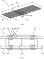
Figure 1 : shows a carriage magnetically suspended from a track segment; -
Figure 2 A: shows a side view of a track segment with a conductor provided in loops; -
Figure 2 B: shows an isometric view of a track segment with a conductor provided in loops; -
Figure 3 : shows a schematic side view of a current signal provided to a conductor; -
Figure 4 : shows a first switch for switching a trajectory of a magnetically suspended carriage; -
Figure 5 : shows a second switch for switching a trajectory of a magnetically suspended carriage; -
Figure 6 : shows an isometric view of a track segment with a conductor provided in loops for three-phase control; -
Figure 7 A: shows a first top view of a track segment with meandered conductors; -
Figure 7 B: shows a second top view of a track segment with meandered conductors; -
Figure 8 : shows a third switch for switching a trajectory of a magnetically suspended carriage; -
Figure 9 : shows a switching module for a track comprising conductor continuously provided at an interface surface; -
Figure 10 : shows a top view of a carriage for operation with the switching module shown byFigure 9 ; and -
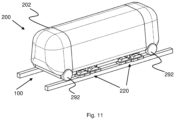
Figure 11 : shows another carriage comprising wheels for carrying the carriage on a track. -
Figure 1 shows acarriage 200 comprising apayload module 202 for carrying goods, people or a combination thereof. Thecarriage 200 is suspended from afirst track segment 100 comprising afirst rail 102 and a second rail 102'. Thefirst rail 102 and the second rail 102' comprise ferromagnetic material and preferably predominantly comprise iron, for example in the form of steel having iron as a majority ingredient. In this embodiment, thefirst track segment 100 comprises two rails, though embodiments comprising one or more than two rails may be envisaged as well. - In the embodiments shown in most of the description, the tracks or track segments comprise two parallel rails, each with its own one or more windings - or conductors - for exciting an electromagnetic force. In other embodiments, the tracks or track segments may comprise one rail only along which the vehicle or carriage is guided. Alternatively, a track may comprise more than two rails. Of these three or more rails, one or more may be provided without windings - preferably in a symmetrical way. In one other embodiment, one main rail may be provided with the track, with two parallel conductors provided as sub-rails on the main rail for guiding the vehicle. Referring to the embodiment as depicted by
Figure 1 , this may main that thefirst rail 102 and the second rail 102' are provided as part of one larger rail, for example a centre rail. - At the top of the
carriage 200,magnetic suspension modules 220 are connected to thepayload module 202 by means of a frame. In this embodiment, amagnetic suspension module 220 is provided at each corner of thecarriage 200. Eachmagnetic suspension module 220 comprises at least one and preferably twoelectromagnets 230. Theelectromagnet 230 comprises acore 232 around which afirst coil 234 and asecond coil 236 are provided. The coils are arranged to be powered by means of an electric current. With a current running through one or both coils, theelectromagnet 230 is powered for providing a suspension force for suspending thecarriage 200 from the first track segment by means of a magnetic force. - The
core 232 of theelectromagnet 230 is curved over an angle of 180°, such that both poles are substantially in the same plane. Depending on how thefirst coil 234 and thesecond coil 236 are provided with a current, the end of thecore 232 around which thefirst coil 234 is provided may be a north pole or a south pole. The end of thecore 232 around which thesecond coil 236 is provided will have a polarity opposite to that of the first end. - The
electromagnet 230 is shown having a U-shape with coils wound around both legs. With respect to the electromagnets, different shapes may be used. - In another embodiment, an electromagnet is provided having an e-shaped core with the legs directed towards the track. Of the legs, one, two or three may be provided with windings for providing an electromagnetic field. Due care is in such embodiment to be taken that the windings are provided and powered such that the summed magnetic field in the outer legs has a magnitude of the magnetic field in the middle leg. Preferably, the magnetic field in the outer legs is the same for each leg.
-
Figure 2 A shows thefirst rail 102 in further detail. The first rail comprises afirst conductor 110 running substantially parallel along thefirst rail 102 and provided in abody 104 of the first rail. The first conductor comprisesfirst conductor segments 112 andsecond conductor segments 114. Thefirst conductor segments 112 andsecond conductor segments 114 have substantially the same length. Furthermore, in one embodiment and the embodiment shown in particular, thefirst conductor segments 112 and thesecond conductor segments 114 have a length substantially the same as the length of thecore 232, as shown byFigure 2 A . - The
first conductor segments 112 and thesecond conductor segments 114 are provided at one and the same side of thebody 104. In this embodiment, thecarriage 200 is suspended below the track by means of an electromagnetic force exerted by theelectromagnets 230 provided on the carriage. Thefirst conductor segments 112 and thesecond conductor segments 114 are provided for adjusting the position of theelectromagnets 230 and with that, of thecarriage 200, relative to the track in a direction perpendicular to the direction of the track, in the plane of the track. To this purpose, thefirst conductor segments 112 and thesecond conductor segments 114 are provided at the bottom surface of therail body 104, at the surface facing theelectromagnets 230. At the surface may indicate that thefirst conductor segments 112 and thesecond conductor segments 114 lie on top of the surface or are fully or partially embedded in the surface. - The
first conductor segments 112 and thesecond conductor segments 114 are arranged such that with a current being provided through thefirst conductor 110, the current through thefirst conductor segments 112 is - from a spatial point of view - opposite to the current through thesecond conductor segments 114. To achieve this, thefirst conductor 110 is provided in thebody 104 in loops. Thesecond conductor segments 114 are provided in the loops and thefirst conductor segments 112 are provided between the loops. - The
first conductor segments 112 and thesecond conductor segments 114 are spaced apart such that the distance between the ends of thecore 232 and in particular the centres thereof is substantially the same as the distance between thefirst conductor segment 112 and thesecond conductor segment 114 and in particular the centres thereof. In this way, if the pole with thefirst coil 234 is located at afirst conductor segment 112, the pole with thesecond coil 236 is located at asecond conductor segment 114. And if the pole with thefirst coil 234 is located at asecond conductor segment 114, the pole with thesecond coil 236 is located at afirst conductor segment 112. Worded differently, the spatial periodicity of thefirst conductor 110 corresponds to the distance between the poles of the electromagnet. The distance between the poles does not define the period: the actual period L is longer and runs from the start of onefirst conductor segment 112 to the start of a directly adjacentfirst conductor segment 112. -
Figure 3 shows an isometric view of thefirst rail 102, showing a multitude ofconductors 110 in parallel. In this particular embodiment, the various line segments of theconductors 110 are aligned.Figure 3 also showsthird conductor segments 116 of which distal parts are connected to distal parts of thesecond segments 114 and proximal parts are connected to distal parts of thefirst conductor segments 112. Furthermore,Figure 3 showsfourth conductor segments 118 of which distal parts are connected to proximal parts of thefirst segments 112 and proximal parts are connected to proximal parts of thesecond conductor segments 114. In this way, loops are constituted in theconductors 110. - The
third conductor segments 116 and thefourth conductor segments 118 are provided at a surface of therail body 104 that is opposite to the side at which thefirst conductor segments 112 and thesecond conductor segments 114 are provided. - As discussed, the
rail 102 of thefirst track segment 110 thus provided is arranged to provide a force to theelectromagnet 230, thus resulting in a movement of thecarriage 200 relative to the track in a direction perpendicular to the direction of the track, in the plane of the track. This force, the Lorentz Force, is proportional to the outer product of the current vector and the magnetic field. With the magnetic field at the interface of therail body 104 and the first conductor segments on one hand and the poles of theelectromagnet 230 on the other hand being substantially perpendicular to one another, the Lorentz force is, withFigure 2 A as reference, in a direction perpendicular to the plane of the image. -
Figure 3 shows afirst graph 300 indicating the current through thefirst conductor 110 as a function of the position of a reference point on theelectromagnet 230 relative to thefirst conductor 110. In this embodiment, thecarriage 200 travels along thefirst track segment 100 with a speed υ, having a component υ par parallel to thefirst rail 102 and parallel to thefirst conductor 110 having a spatial periodicity L. To ensure smooth movement of thecarriage 200 relative to the first track segment, the current in thefirst conductor 100 is to be an alternating current. This is important, as each conductor segment is firstly passed by a first pole of theelectromagnet 230 having a first polarity and subsequently by a second pole of theelectromagnet 230 having a second opposite polarity. If the current through the first conductor would not alternate, alternating (electromechanical) Lorentz force would be applied to the carriage, with a uncomfortable ride of the passengers as a consequence. - To ensure smooth movement, the frequency of the alternating current I through the
first conductor 110 is dependent on the speed of the carriage relative to thefirst rail 102. Preferably, the current is provided as follows:
- with
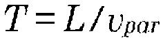
- with a being a constant defining the maximum current, t being time, T being the period of the signal and the time period during which the
electromagnet 230 travel the period of thefirst conductor 110, υ being the speed of the carriage and c being a constant such that a maximum current is provided when either the first pole or the second pole of theelectromagnet 230 passes thefirst conductor segment 112. -
Figure 4 shows aswitch 400 for switching direction of travel of thecarriage 200 from a first track segment 410 to either asecond track segment 420 or athird track segment 430. Thecarriage 200 is propelled along a track comprising thefirst track segment 140, thesecond track segment 420 and thethird track segment 430. This may be effectuated by means of a further conductor winding provided along the rails of the track. At the junction between the first track segment 410 on one hand and thesecond track segment 420 and thethird track segment 430 on the other hand, afirst switching rail 120 and a second switching rail 120' are provided in the track, in parallel to one another. If the track is constituted by means of only one rail, only one switching rail is provided. - The
first switching rail 120 and the second switching rail 120' comprising a multitude of conductors as depicted byFigure 2 B . the conductors of thefirst switching rail 120 and the second switching rail 120' are powered as discussed above in conjunction withFigure 3 . By virtue of powering theconductors 110 in thefirst switching rail 120 and the second switching rail 120', thecarriage 200 is moved to the left of the first track segment 410 or to the right of the first track segment 410, depending on what direction the current flows at the moment a particular pole passes a particular segment of theconductor 110 provided at a surface of the switchingrail 120 and the second switching rail 120' facing theelectromagnet 230 of thecarriage 200. - With the
switch 400, thesecond track segment 420 overlaps thethird track segment 430. More in particular, the left rail of thesecond track segment 420 overlaps with the right rail of thethird track segment 430. The switch is operated such that edges of thecarriage 200 are moved to the left or to the rights side of thefirst switching rail 120 and the second switching rail 120'. Once at the intended side, thecarriage 200 is controlled to deep thecarriage 200 at the intended side of thefirst switching rail 120 and the second switching rail 120' to follow its course from the first track segment 410 to either thesecond track segment 420 or thethird track segment 430. -
Figure 5 shows anotherswitch 500, providing switching functionality from afirst track segment 510 to either asecond track segment 520 or athird track segment 530 in which thesecond track segment 520 does not overlap with the third track segment. In theswitch 500, aswitching block 540 is provided havingconductors 110 arranged thereon as depicted byFigure 2 B . During travelling of thecarriage 200 along theswitching block 540, theconductors 110 are powered by a current as discussed above to enable a sideway movement of the carriage relative to theswitching block 540 if thecarriage 200 is to continue traveling along the track via thethird track segment 530. If, on the other hand, thecarriage 200 is to continue along the track via thesecond track segment 520, theconductors 110 are preferably not powered to enable thecarriage 200 to continue in a substantially straight line. - So far, a one-phase system has been discussed for providing a force to enable the
carriage 200 to switch track segments.Figure 6 shows afurther switching segment 120 arranged to be powered by a three-phase current. Theswitching segment 120 comprises groups of three conductors, afirst phase conductor 110, a second phase conductor 110' and athird phase conductor 110". In this embodiment, the three phase conductors are shifted relative to one another by a sixth of a spatial period of the windings. In another embodiment, the three phase conductors are shifted relative to one another by a third of a spatial period of the windings. In the latter embodiment, the phases of the switching currents through the conductors are skewed by a third of a period. In the first embodiment, the phases of the switching currents through the conductors are skewed by a sixth of a period. -
Figure 7 A shows another embodiment of arail segment 102 arranged to enable thecarriage 200 to switch from one track segment to another track segment. Therail segment 102 comprises arail body 104. At one surface of therail body 104, either fully or partially embedded at the surface or on the surface, afirst conductor 130 and a second conductor 130' are provided. Thefirst conductor 130 and the second conductor 130' are preferably provided in one plane that substantially coincides with the surface at which the conductors are provided. Relative to the electromagnets provided on thecarriage 130, this is the surface of therail body 104 that faces the carriage. - The
first conductor 130 and the second conductor 130' have a meandering shape, withfirst segments 132 of thefirst conductor 130 and first segments 132' of the second conductor 130' provided at the surface of therail body 104 andsecond segments 134 of thefirst conductor 130 and second segments 134' of the second conductor 130' being provided away from therail body 104. With therail body 104 predominantly comprising a ferromagnetic metal like iron, as discussed before, only the field generated by the first conductor segments benefits from the ferromagnetic characteristics of therail body 104. -
Figure 7 A also shows theelectromagnet 230. With the position of theelectromagnet 230 as depicted byFigure 7 A , the pole surrounded by thesecond coil 236 is under the influence of thefirst conductor segment 132 of thefirst conductor 130 and of the first conductor segment 132' of the second conductor 130'. As thesecond segments 134 of thefirst conductor 130 and the second segments 134' of the second conductor 130' are located away from theferromagnetic rail body 104, the influence of the magnetic field generated by thesesecond conductor segments 134 on the pole with thefirst coil 234 is negligible relative to the effect of the magnetic field generated by thefirst conductor segments 132. - With the
first coil 234 and thesecond coil 236 being provided with a direct current, thefirst conductor 130 and the second conductor 130' are preferably provided with an alternating current. The frequency of the alternating current is calculated in the same way as discussed above:
- with

- with a being a constant defining the maximum current, t being time, T being the period of the signal and the time period during which the
electromagnet 230 travel the period L of theconductors 220, υ being the speed of the carriage and c being a constant such that a maximum current is provided when either the first pole or the second pole of theelectromagnet 230 passes thefirst conductor segment 132. - Depending on the direction of the current through the conductors - from left to right or opposite -, a force to the left or the right - in the drawing: up or down - is exerted on the
electromagnet 230 and therefore on thecarriage 130. The force exerted is the Lorentz force and can be calculated accordingly. That is, if the centre of thecore 232 coincides with centres of the first conductor segments. -
Figure 7 B shows the position of theelectromagnet 230 slightly shifted relative to the conductor segments. In the configuration as depicted byFigure 7 B , poles of the electromagnet are positioned at thethird conductor segments 136 of thefirst conductor 130 and third conductor segments 136' of the second conductor 130'. At this position, the current in the conductors flows perpendicular to the length of the track segment and the traveling direction of thecarriage 200. And provided current flows in thefirst conductor 130 and the second conductor 130' in the same direction along the track, the currents in thefirst conductor 130 and the second conductor 130' are now at the locations of the poles flowing in opposite directions. This may result in unwanted electromechanical effects. Two option are available to address this effect. - Firstly, the current signals are provided in accordance with the formula provided above. This means that if centres of the poles coincide with the third track segments, the current through the conductors is zero. Second, if the position of a centre of a pole coincides with the third conductor segments, the currents in the
third conductor segments 136 of thefirst conductor 130 and third conductor segments 136' of the second conductor 130' are provided such that they are provided in the same direction. As an effect, they exert a force on theelectromagnet 230 and hence, on thecarriage 200 in a direction substantially parallel to the travelling direction of thecarriage 200 and/or the length of the track - either in the direction of travel or opposite thereto. - By virtue of this effect, the embodiment of the rail segment as shown by
Figure 7 A andFigure 7 B may be used for switching functionality as well as for propulsion functionality. This, in turn, means that no further windings are required on the rails for propelling thecarriage 200 along the track. It is noted that this embodiment required control of the currents different from control as provided by means of the formula provided above. -
Figure 8 shows aswitch 800 provided in a track for thecarriage 200. Theswitch 800 is provided for switching direction of thecarriage 200 from afirst track segment 810 to one of asecond track segment 820 and athird track segment 830. Thefirst track segment 810 comprises afirst rail 812 and a second rail 812', thesecond track segment 820 comprises afirst rail 822 and a second rail 822' and thethird track segment 830 comprises afirst rail 832 and a second rail 832'. - On the
first rail 812 of thefirst track segment 810, thefirst conductor 130 and the second conductor 130' are provided. In an equivalent way, the second rail 812' of thefirst track segment 810 is provided with athird conductor 130" and afourth conductor 130"'. Thefirst conductor 130 continues from thefirst rail 812 of thefirst track segment 810 to thefirst rail 822 of the second track segment. The second conductor 130' continues from thefirst rail 812 of thefirst track segment 810 to thefirst rail 832 of thethird track segment 830. Thethird conductor 130" continues from the second rail 812' of thefirst track segment 810 to the second rail 822' of thesecond track segment 820. And thefourth conductor 130‴ continues from the second rail 812' of thefirst track segment 810 to the second rail 832' of thethird track segment 830. - It is noted that in this, but also in other embodiment, the conductors are not necessarily one physical conductor. Additionally or alternatively, the conductors may be provided by means of multiple modules, either connected by means of, for example, ohmic contacts, or electrically isolated. Yet, it is preferred the conductor modules form one functional conductor that is arranged to provide the switching functionality as discussed above.
-
Figure 9 shows yet another embodiment of aswitching module 900 that may be incorporated in a switch. Rather than theconductors 930 being intermittently provided at the interface surface of themodule body 900 at the interface with theelectromagnet 230, theconductors 930 are provided at the surface in a continuous fashion, substantially parallel to the length of the track and the intended direction of thecarriage 200. This requires an orientation of theelectromagnet 230 relative to the track different than depicted inFigure 1 . This is depicted inFigure 9 and Figure 10 . - Rather than the poles being provided in a line substantially parallel to the track length and the intended direction of movement, the poles are provided on a line substantially perpendicular to the track length and the intended direction of movement.
Figure 10 shows this in further detail, in a top view from thecarriage 200 and afirst track segment 100. For position control of thecarriage 200 relative to the track,magnetic suspension modules 220 are provided at each corner of the payload module by means of aframe 204. Eachmagnetic suspension module 220 comprises at least one and preferably twoelectromagnets 230. If themagnetic suspension module 220 comprises twoelectromagnets 230, they are slightly skewed relatively to one another in over the line through the two poles. Theelectromagnet 230 comprises acore 232 around which afirst coil 234 and asecond coil 236 are provided. The coils are arranged to be powered by means of an electric current. With a current running through one or both coils, theelectromagnet 230 is powered. - Also from a control point of view, the embodiment shown by
Figure 9 requires the conductors to be powered in another way. In the embodiment shown byFigure 2 A andFigure 2 B a substantially constant sine shape current signal is to be provided - provided the carriage travels at continuous forward velocity. For the amount of sideway movement, only the intensity of the current is to be controlled. On the other hand, the configuration as shown byFigure 9 requires switching of currents per conductors, at a frequency depending on the transversal movement speed of thecarriage 200 relative to theswitching module 900 as shown byFigure 9 . - As discussed, the embodiments discussed above may be combined with additional windings that are provided for propulsion of the
carriage 200. Such windings comprise first segments provided at the carriage interface surface of the rail or the rails of the track, substantially perpendicular to the length of the track. These first windings are connected by means of second segments that may be provided parallel to the length of the rails and that are provided away from the rails to ensure the magnetic field induced by the second segments is significantly less than the magnetic induced by the first segments. Such windings may be provided in single mode, in three-phase mode as discussed above or in another configuration. - Thus far, embodiments have been disclosed with a carriage suspended from the track. The various aspects and further characteristics thereof may also be employed in other embodiment in which the carriage is provided above the tracks. In such embodiment, depicted by
Figure 11 , the carriages rolls over thetrack 100 by means ofwheels 292. Thewheels 292 do not have substantial extensions that reach beyond the main diameter of thewheels 292 to enable switching to other track segments at a switch only by controlling the electromagnetic functionality of the switches. - In another embodiment, the
carriage 200 is provided above thetrack 100 and themagnetic suspension modules 220 are provided below thetrack 100. In such embodiments, overlapping rails in a switch are omitted. This means that with fourmagnetic suspension modules 220 provided on thecarriage 200, thecarriage 200 is in such switches suspended by only threemagnetic suspension modules 220. - In summary, the various aspects relate to a switch is presented for a magnetically suspended or at least guided vehicle. The switch comprises a fork from a first track segment to a second and third track segment. An elongate conductive module, for example a conductive wire is provided along at least the first track segment and optionally along the second and third track segment. The conductive module comprises conductor segments that guide a current with a directional component substantially parallel the length of the track, at a first surface of the track. With an electromagnet provided on a carriage having a pole directed to the first surface of the track, a Lorentz force may be provided for urging the carriage in a direction perpendicular to the length of the track. This allows a carriage moving along the first track segment to be urged towards the second or third track segment at the other side of the fork.
- The embodiments discussed thus far are discussed in conjunction with conductor segments having a directional component parallel to the length of the tracks in general and the rails in particular. These conductor segments are discussed for guiding the vehicle to a particular position on the track selection module, towards one or two or more tracks of the switch. If these conductor segments are provided perpendicular to the length of the track, the conductor segments may be used for determining the position of the vehicle on the track in a direction perpendicular to the length of the track and, hence, perpendicular to the main direction of movement of the vehicle along the track.
- If these conductor segments are provided diagonally relative to the length of the track, the conductor segments may be used for establishing displacement of the vehicle relative to the rails in a direction parallel to the track as well as perpendicular to the track - in any case substantially perpendicular to the length of the conductor segments.
- Whereas this embodiment may be advantageous from a material and therefore cost point of view, it is not a preferred embodiment. In a preferred embodiment, the amount and speed of displacement perpendicular to the length of the track and parallel to the track, along the track, may be controlled independent from one another. Therefore, an embodiment comprising conductor segments substantially parallel to the tracks and the rails in particular on one hand and further conductor segments substantially perpendicular to the tracks and the rails in particular on the other hand is particularly preferred. With the conductor segments and the independent conductor segments being powered independently, this embodiment allows for independent forward and sideway speed and displacement control.
- In the description above, it will be understood that when an element such as layer, region or substrate is referred to as being "on" or "onto" another element, the element is either directly on the other element, or intervening elements may also be present. Also, it will be understood that the values given in the description above, are given by way of example and that other values may be possible and/or may be strived for.
- Furthermore, the invention may also be embodied with less components than provided in the embodiments described here, wherein one component carries out multiple functions. Just as well may the invention be embodied using more elements than depicted in the Figures, wherein functions carried out by one component in the embodiment provided are distributed over multiple components.
- It is to be noted that the figures are only schematic representations of embodiments of the invention that are given by way of non-limiting examples. For the purpose of clarity and a concise description, features are described herein as part of the same or separate embodiments, however, it will be appreciated that the scope of the invention, defined by the appended claims, may include embodiments having combinations of all or some of the features described. The word 'comprising' does not exclude the presence of other features or steps than those listed in a claim. Furthermore, the words 'a' and 'an' shall not be construed as limited to 'only one', but instead are used to mean 'at least one', and do not exclude a plurality.
- A person skilled in the art will readily appreciate that various parameters and values thereof disclosed in the description may be modified and that various embodiments disclosed and/or claimed may be combined without departing from the scope of the invention, defined by the appended claims.
- It is stipulated that the reference signs in the claims do not limit the scope of the claims, but are merely inserted to enhance the legibility of the claims.
Claims (23)
- Switch (400, 500, 800) for a track for guiding transportation of a magnetically suspended and/or magnetically guided vehicle (200) along the track, the switch comprising:- A first elongate track segment (410, 420, 430, 510, 520, 530, 810, 820, 830);- A second elongate track segment (410, 420, 430, 510, 520, 530, 810, 820, 830);- A third elongate track segment (410, 420, 430, 510, 520, 530, 810, 820, 830);- A track selection module (120, 540) for selecting between a first guidance mode in which the vehicle is guided from the first track segment to the second track segment and a second guidance mode in which the vehicle is guided from the first track segment to the third track segment;characterised in that:- The track segments comprise a ferromagnetic material; and- the track selection module comprises a first elongate electrical conductor (110, 110', 110", 130, 130') having first conductor segments (112, 114, 116, 118, 132, 134, 136) that are arranged to guide a current through the conductor with a directional component substantially parallel the length of the track located at a first surface at a vehicle side of the track which first conductor segments have a directional component parallel to the length of the track segments.
- Switch (400, 500, 800) according to claim 1, wherein the first elongate electrical conductor (110, 110', 110", 130, 130') comprises second conductor segments (112, 114, 116, 118, 132, 134, 136) located away from the first surface and the first conductor segments and the second conductor segments of the first elongate electrical conductor are alternated.
- Switch (400, 500, 800) according to claim 2, wherein the second conductor segments (112, 114, 116, 118, 132, 134, 136) of the first elongate electrical conductor are located in substantially the same plane as the first surface, at a distance from the first track segment (410, 420, 430, 510, 520, 530, 810, 820, 830)at a first side of the first elongate track segment (140, 510, 810).
- Switch (400, 500, 800) according to claim 3, further comprising a second elongate electrical conductor (110, 110', 110", 130, 130') alternately comprising first conductor segments (112, 114, 116, 118, 132, 134, 136) and second conductor segments (112, 114, 116, 118, 132, 134, 136), wherein:- The first conductor segments of the second elongate electrical conductor (110, 110', 110", 130, 130') are provided at the first surface, the first conductor segments (112, 114, 116, 118, 132, 134, 136) having a directional component parallel to the length of the track segments (410, 420, 430, 510, 520, 530, 810, 820, 830); and- The second conductor segments (410, 420, 430, 510, 520, 530, 810, 820, 830) of the second elongate electrical conductor (110, 110', 110", 130, 130') are located away from the first surface and the second conductor segments (112, 114, 116, 118, 132, 134, 136) of the first elongate electrical conductor (110, 110', 110", 130, 130').
- Switch (400, 500, 800) according to claim 4, wherein first conductor segments (112, 114, 116, 118, 132, 134, 136) of the first elongate electrical conductor (110, 110', 110", 130, 130') are parallel to the first conductor segments (112, 114, 116, 118, 132, 134, 136) of the second elongate electrical conductor (110, 110', 110", 130, 130') and second conductor segments (112, 114, 116, 118, 132, 134, 136) of the first elongate electrical conductor (110, 110', 110", 130, 130') parallel to second segments of the second elongate electrical conductor(110, 110', 110", 130, 130').
- Switch (400, 500, 800) according to claim 4 or 5, wherein the first elongate electrical conductor (110, 110', 110", 130, 130') continues from first track segment (410, 420, 430, 510, 520, 530, 810, 820, 830)to second track segment (410, 420, 430, 510, 520, 530, 810, 820, 830)and second elongate electrical conductor (110, 110', 110", 130, 130') continues from first track segment to third track segment.
- Switch (400, 500, 800) according to any of the claims 4 to 6, wherein:- The first elongate electrical conductor (110, 110', 110", 130, 130') and the second elongate electrical conductor (110, 110', 110", 130, 130') comprise third conductor segments (112, 114, 116, 118, 132, 134, 136) for connecting the first conductor segments (112, 114, 116, 118, 132, 134, 136) to the second conductor segments (112, 114, 116, 118, 132, 134, 136) ;- The first conductor segments are substantially parallel to the length of the track segments (410, 420, 430, 510, 520, 530, 810, 820, 830); and- The third conductor segments are substantially perpendicular to the length of the track segments.
- Switch (400, 500, 800) according to any of the claims 4 to 7, wherein the second conductor segments (112, 114, 116, 118, 132, 134, 136) are substantially parallel to the track segments (410, 420, 430, 510, 520, 530, 810, 820, 830) and the first conductor segments (112, 114, 116, 118, 132, 134, 136) and second conductor segments have substantially the same lengths.
- Switch (400, 500, 800) according to any of the claims 4 to 8, wherein:- the second track segment (410, 420, 430, 510, 520, 530, 810, 820, 830) and the third track segment (410, 420, 430, 510, 520, 530, 810, 820, 830) are connected to the first track segment (410, 420, 430, 510, 520, 530, 810, 820, 830) in extension of the first track segment;- the second track segment and the third track segment diverge; and- the first elongate electrical conductor (110, 110', 110", 130, 130') is provided on the first track segment and the second track segment and the second elongate electrical conductor (110, 110', 110", 130, 130') is provided on the first track segment and the third track segment.
- Switch (400, 500, 800) according to claim 1, the first elongate electrical conductor (110, 110', 110", 130, 130') further comprising second conductor segments (112, 114, 116, 118, 132, 134, 136) provided at the first surface, the second conductor segments having a directional component substantially parallel to the first conductor segments (112, 114, 116, 118, 132, 134, 136) and arranged to direct the current through the first conductor in a direction substantially opposite to direction of the current through the first conductor segments.
- Switch (400, 500, 800) according to claim 10, wherein:- the first elongate electrical conductor (110, 110', 110", 130, 130') comprises a multitude of loops;- the first conductor segments (112, 114, 116, 118, 132, 134, 136) are provided between the loops; and- the second conductor segments (112, 114, 116, 118, 132, 134, 136) are provided as part of the loops.
- Switch (400, 500, 800) according to claim 11, further comprising third conductor segments (112, 114, 116, 118, 132, 134, 136) and fourth conductor segments (112, 114, 116, 118, 132, 134, 136) located away from the first surface, wherein:- distal parts of third conductor segments are connected to distal parts of the second conductor segments (112, 114, 116, 118, 132, 134, 136) and proximal parts of the third conductor segments are connected to distal parts of the first conductor segments (112, 114, 116, 118, 132, 134, 136) ; and- distal parts of the fourth conductor segments are connected to proximal parts of the first conductor segments and proximal parts of the fourth conductor segments are connected to proximal pats of the second conductor segments.
- Switch (400, 500, 800) according to any of the claims 10 to 12, wherein the first conductor segments (112, 114, 116, 118, 132, 134, 136) and the second conductor segments (112, 114, 116, 118, 132, 134, 136) are provided substantially in extension of one another in a spatially periodically repeating pattern having a periodic length L.
- Switch (400, 500, 800) according to claim 13, further comprising:- a second elongate electrical conductor (110, 110', 110", 130, 130') comprising first conductor segments (112, 114, 116, 118, 132, 134, 136) and second conductor segments (112, 114, 116, 118, 132, 134, 136) and shaped similarly as the first elongate electrical conductor (110, 110', 110", 130, 130'); and- a third elongate electrical conductor (110, 110', 110", 130, 130') comprising first conductor segments and second conductor segments and shaped similarly as the first elongate electrical conductor,Wherein:- the first conductor segments and the second conductor segments of the first elongate electrical conductor, the second conductor and the third elongate electrical conductor have substantially the same length;- the first segments and the second segments of the first elongate electrical conductor (110, 110', 110", 130, 130') are skewed relative to the first segments and the second segments of the second elongate electrical conductor (110, 110', 110", 130, 130') by substantially a third of the period L; and- the first segments and the second segments of the second elongate electrical conductor are skewed relative to the first segments and the second segments of the third elongate electrical conductor (110, 110', 110", 130, 130') by substantially a third of the period L.
- Switch (400, 500, 800) according to any of the claims 10 to 14, wherein:- the second track segment (410, 420, 430, 510, 520, 530, 810, 820, 830) and the third track segment (410, 420, 430, 510, 520, 530, 810, 820, 830) are connected to the first track segment (410, 420, 430, 510, 520, 530, 810, 820, 830) in extension of the first track segment;- the second track segment and the third track segment diverge; and- the first conductor segments (112, 114, 116, 118, 132, 134, 136) and the second conductor segments (112, 114, 116, 118, 132, 134, 136) are provided on the first track segment.
- Switch (400, 500, 800) according to any of the claims 10 to 14, wherein the second track segment (410, 420, 430, 510, 520, 530, 810, 820, 830) does not overlap with the third track segment (410, 420, 430, 510, 520, 530, 810, 820, 830) and the track selection module is provided between the first track segment (410, 420, 430, 510, 520, 530, 810, 820, 830) on a first side of the switch and the second track segment and the third track segment on a second side of the switch opposite to the first side.
- Switch (400, 500, 800) according to claim 1, further comprising a multitude of further conductor segments (112, 114, 116, 118, 132, 134, 136) provided substantially parallel to one another, the further conductor segments having a directional component substantially parallel to the length of the track segments (410, 420, 430, 510, 520, 530, 810, 820, 830).
- Switch (400, 500, 800) according to claim 17, wherein the conductor segments are connected to provide continuous conductors.
- Transportation system for guiding a magnetically suspended and/or magnetically guided vehicle (200) comprising:- a substantially closed conduit arranged to be brought at a pressure of less than 0.9 bar and preferably less than 0.1 bar;- a track provided in the conduit, the track comprising a switch (400, 500, 800) according to any of the preceding claims.
- Vehicle (200) arranged for transport along a track comprising a switch (400, 500, 800) according to any of the claims 1 to 16, the vehicle comprising a first electromagnet (230) comprising a core (232) around which a first coil (234) and a second coil (236) are provided, the electromagnet (230) having a north pole and a south pole provided at a distance from one another, whereby the core (232) is curved over an angle of 180°, such that both poles are in substantially the same plane, whereby, depending on how the first coil (234) and the second coil (236) are provided with a current, the end of the core (232) around which the first coil (234) is provided may be a north pole or a south pole, and whereby the end of the core (232) around which the second coil (236) is provided will have a polarity opposite to that of the first end, wherein the magnetic field lines at the north pole and the south pole are substantially parallel to one another and substantially perpendicular to the intended direction of transportation of the vehicle.
- Vehicle (200) according to claim 20, wherein the north pole and the south pole are provided in a line substantially parallel to the intended direction of transportation.
- Vehicle (200) according to claim 21, further comprising a second magnet (230) similarly shaped as the first magnet(230), wherein the poles of the second magnet are skewed relative to the poles of the first magnet by less than the distance between the north poles and the south poles perpendicular to the line between the south poles and the north poles.
- Vehicle (200) according to claim 20 to the extent arranged for a track comprising a switch (400, 500, 800) according to any of the claim 17 or claim 18, wherein the north pole and the south pole are provided in a line substantially perpendicular to the intended direction of transportation.
Applications Claiming Priority (2)
| Application Number | Priority Date | Filing Date | Title |
|---|---|---|---|
| NL2019259A NL2019259B1 (en) | 2017-07-17 | 2017-07-17 | Switch for a track for guiding transportation of a vehicle |
| PCT/NL2018/050489 WO2019017775A1 (en) | 2017-07-17 | 2018-07-16 | Switch for a track for guiding transportation of a vehicle |
Publications (3)
| Publication Number | Publication Date |
|---|---|
| EP3655586A1 EP3655586A1 (en) | 2020-05-27 |
| EP3655586B1 true EP3655586B1 (en) | 2025-06-18 |
| EP3655586C0 EP3655586C0 (en) | 2025-06-18 |
Family
ID=60813913
Family Applications (1)
| Application Number | Title | Priority Date | Filing Date |
|---|---|---|---|
| EP18766357.0A Active EP3655586B1 (en) | 2017-07-17 | 2018-07-16 | Switch for a track for guiding transportation of a vehicle |
Country Status (11)
| Country | Link |
|---|---|
| US (1) | US11541761B2 (en) |
| EP (1) | EP3655586B1 (en) |
| JP (1) | JP7256182B2 (en) |
| KR (1) | KR102535003B1 (en) |
| CN (1) | CN111032956B (en) |
| AU (1) | AU2018303466B2 (en) |
| CA (1) | CA3070047A1 (en) |
| ES (1) | ES3034586T3 (en) |
| NL (1) | NL2019259B1 (en) |
| PL (1) | PL3655586T3 (en) |
| WO (1) | WO2019017775A1 (en) |
Families Citing this family (7)
| Publication number | Priority date | Publication date | Assignee | Title |
|---|---|---|---|---|
| US11433728B2 (en) | 2017-06-30 | 2022-09-06 | Hyperloop Technologies, Inc. | Active control system |
| AU2018302260A1 (en) * | 2017-07-21 | 2020-01-30 | Hyperloop Technologies, Inc. | Vehicle-based guided switching |
| EP4230467A1 (en) | 2017-07-27 | 2023-08-23 | Hyperloop Technologies, Inc. | Augmented permanent magnet system |
| NL2020480B1 (en) | 2018-02-22 | 2019-08-29 | Hardt Ip B V | Method of controlling a direction of a trajectory of a vehicle |
| NL2027018B1 (en) | 2020-12-01 | 2022-07-06 | Hardt Ip B V | Switch for a track of a transportation system |
| NL2031207B1 (en) | 2022-03-09 | 2023-09-18 | Hardt Ip B V | Control for linear reluctance motor |
| NL2031211B1 (en) | 2022-03-09 | 2023-09-18 | Hardt Ip B V | Linear reluctance motor |
Family Cites Families (15)
| Publication number | Priority date | Publication date | Assignee | Title |
|---|---|---|---|---|
| DE2220735A1 (en) * | 1972-01-20 | 1973-11-08 | Krauss Maffei Ag | ARRANGEMENT FOR NON-CONTACT MAGNETIC CARRYING OF A HOVER VEHICLE IN THE AREA OF A ROAD BREAKING |
| JPS5820201B2 (en) | 1975-02-10 | 1983-04-22 | 三菱電機株式会社 | Jikikido Souchino Kidoubunki System |
| JPS6015362Y2 (en) | 1983-02-24 | 1985-05-15 | 三菱電機株式会社 | magnetic orbit device |
| JPH04193007A (en) | 1990-11-26 | 1992-07-13 | Hitachi Ltd | 5-fold power supply method |
| JPH0537773U (en) | 1991-10-24 | 1993-05-21 | 三菱重工業株式会社 | AC magnetic levitation carrier |
| KR0130945B1 (en) | 1994-06-21 | 1998-04-14 | 김인기 | Travel Control System of Passenger Rapid Transport System |
| US5503083A (en) * | 1994-06-23 | 1996-04-02 | Powell; James R. | Electromagnetic induction suspension and horizontal switching system for a vehicle on a planar guideway |
| JP2001057712A (en) * | 1999-08-18 | 2001-02-27 | Toyota Autom Loom Works Ltd | Linear motor driven carrying vehicle |
| KR100373990B1 (en) | 2000-02-03 | 2003-03-04 | 주식회사 스카이카 | A personal rapid transit positioning a linear induction motor on the bottom of vehicle |
| DE10357264B4 (en) * | 2003-12-02 | 2010-12-30 | Leibniz-Institut Für Festkörper- Und Werkstoffforschung Dresden E.V. | Device for providing directional changes for superconducting magnetic levitation systems |
| US20080148988A1 (en) | 2006-12-20 | 2008-06-26 | John Lee Wamble | Guideway switch apparatus for magnetically levitated vehicles |
| KR101006850B1 (en) | 2008-12-30 | 2011-01-12 | 한국철도기술연구원 | Wheeled High Speed Tube Rail System |
| DE102013218389B4 (en) * | 2013-09-13 | 2023-01-12 | Krones Ag | Device and method for switching a passive switch for transport systems with linear motors |
| AT517219B1 (en) | 2015-06-23 | 2016-12-15 | Bernecker + Rainer Industrie-Elektronik Ges M B H | Method and long-stator linear motor for transferring a transport unit at a transfer position |
| CN205804057U (en) | 2016-03-24 | 2016-12-14 | 西南交通大学 | A kind of magnetic turnout |
-
2017
- 2017-07-17 NL NL2019259A patent/NL2019259B1/en active
-
2018
- 2018-07-16 PL PL18766357.0T patent/PL3655586T3/en unknown
- 2018-07-16 CA CA3070047A patent/CA3070047A1/en active Pending
- 2018-07-16 AU AU2018303466A patent/AU2018303466B2/en not_active Ceased
- 2018-07-16 ES ES18766357T patent/ES3034586T3/en active Active
- 2018-07-16 JP JP2020524704A patent/JP7256182B2/en active Active
- 2018-07-16 WO PCT/NL2018/050489 patent/WO2019017775A1/en not_active Ceased
- 2018-07-16 CN CN201880053271.XA patent/CN111032956B/en active Active
- 2018-07-16 US US16/631,988 patent/US11541761B2/en active Active
- 2018-07-16 KR KR1020207003953A patent/KR102535003B1/en active Active
- 2018-07-16 EP EP18766357.0A patent/EP3655586B1/en active Active
Also Published As
| Publication number | Publication date |
|---|---|
| EP3655586A1 (en) | 2020-05-27 |
| AU2018303466A1 (en) | 2020-02-13 |
| US20200164750A1 (en) | 2020-05-28 |
| PL3655586T3 (en) | 2025-09-01 |
| CN111032956A (en) | 2020-04-17 |
| AU2018303466B2 (en) | 2023-10-26 |
| WO2019017775A1 (en) | 2019-01-24 |
| JP2020528261A (en) | 2020-09-17 |
| CN111032956B (en) | 2022-07-05 |
| KR20200032711A (en) | 2020-03-26 |
| EP3655586C0 (en) | 2025-06-18 |
| JP7256182B2 (en) | 2023-04-11 |
| ES3034586T3 (en) | 2025-08-20 |
| US11541761B2 (en) | 2023-01-03 |
| NL2019259B1 (en) | 2019-01-30 |
| KR102535003B1 (en) | 2023-05-22 |
| CA3070047A1 (en) | 2019-01-24 |
Similar Documents
| Publication | Publication Date | Title |
|---|---|---|
| EP3655586B1 (en) | Switch for a track for guiding transportation of a vehicle | |
| KR101544383B1 (en) | Magnetic levitation system having switch for guide elctromagnetic and stoping method thereof | |
| US6633217B2 (en) | Inductrack magnet configuration | |
| US6758146B2 (en) | Laminated track design for inductrack maglev systems | |
| JP7452952B2 (en) | Long stator linear motor with method for transitioning conveying unit in transition position | |
| US6827022B2 (en) | Magnetic levitation and propulsion system | |
| CN102897054B (en) | Haulage system with suspension that magnetic advances, placed in the middle | |
| US10604898B2 (en) | Rail-bound maglev train | |
| JP6002694B2 (en) | Equipment for inductive energy transmission | |
| CN111373097B (en) | Permanent magnetic suspension train adopting passive low-frequency electromagnetic stabilization | |
| JP2002503437A (en) | Traveling system for magnetic levitation vehicles | |
| KR20030076801A (en) | A Integrated System Of Non-Contact Power Feed System And Transverse Flux Linear Motor With Permanent Magnetic Excitation | |
| JP7083886B2 (en) | Transport device and transport path | |
| US5253592A (en) | Magnetic levitation configuration incorporating levitation, guidance and linear synchronous motor | |
| CN105196788B (en) | Rotating-speed-controllable repulsion magnetic suspension wheel with inner wheel body and outer wheel body separated | |
| US7255046B2 (en) | Method and apparatus for use in guiding magnetically levitated vehicles | |
| JP4000644B2 (en) | Transport vehicle traveling system | |
| HK40017247B (en) | Switch for a track for guiding transportation of a vehicle | |
| HK40017247A (en) | Switch for a track for guiding transportation of a vehicle | |
| JP2009142137A (en) | Magnetic levitation propulsion device | |
| JPH0669246B2 (en) | Levitating, guiding and propulsion combination device for induction repulsion type magnetic levitation railway | |
| KR100326145B1 (en) | A non-contact power feed system of traverse flux machine | |
| JP4631405B2 (en) | Magnetic levitation propulsion device | |
| JP2834474B2 (en) | DC linear motor | |
| JP4324589B2 (en) | Magnetic levitation propulsion system and magnetic levitation railway |
Legal Events
| Date | Code | Title | Description |
|---|---|---|---|
| STAA | Information on the status of an ep patent application or granted ep patent |
Free format text: STATUS: UNKNOWN |
|
| STAA | Information on the status of an ep patent application or granted ep patent |
Free format text: STATUS: THE INTERNATIONAL PUBLICATION HAS BEEN MADE |
|
| PUAI | Public reference made under article 153(3) epc to a published international application that has entered the european phase |
Free format text: ORIGINAL CODE: 0009012 |
|
| STAA | Information on the status of an ep patent application or granted ep patent |
Free format text: STATUS: REQUEST FOR EXAMINATION WAS MADE |
|
| 17P | Request for examination filed |
Effective date: 20200122 |
|
| AK | Designated contracting states |
Kind code of ref document: A1 Designated state(s): AL AT BE BG CH CY CZ DE DK EE ES FI FR GB GR HR HU IE IS IT LI LT LU LV MC MK MT NL NO PL PT RO RS SE SI SK SM TR |
|
| AX | Request for extension of the european patent |
Extension state: BA ME |
|
| DAV | Request for validation of the european patent (deleted) | ||
| DAX | Request for extension of the european patent (deleted) | ||
| STAA | Information on the status of an ep patent application or granted ep patent |
Free format text: STATUS: EXAMINATION IS IN PROGRESS |
|
| 17Q | First examination report despatched |
Effective date: 20210316 |
|
| RAP3 | Party data changed (applicant data changed or rights of an application transferred) |
Owner name: HARDT IP B.V. |
|
| RIN1 | Information on inventor provided before grant (corrected) |
Inventor name: GEUZE, MARIJN JESPER Inventor name: KOOGER, BAUKE JAN |
|
| GRAP | Despatch of communication of intention to grant a patent |
Free format text: ORIGINAL CODE: EPIDOSNIGR1 |
|
| STAA | Information on the status of an ep patent application or granted ep patent |
Free format text: STATUS: GRANT OF PATENT IS INTENDED |
|
| INTG | Intention to grant announced |
Effective date: 20250109 |
|
| GRAS | Grant fee paid |
Free format text: ORIGINAL CODE: EPIDOSNIGR3 |
|
| GRAA | (expected) grant |
Free format text: ORIGINAL CODE: 0009210 |
|
| STAA | Information on the status of an ep patent application or granted ep patent |
Free format text: STATUS: THE PATENT HAS BEEN GRANTED |
|
| AK | Designated contracting states |
Kind code of ref document: B1 Designated state(s): AL AT BE BG CH CY CZ DE DK EE ES FI FR GB GR HR HU IE IS IT LI LT LU LV MC MK MT NL NO PL PT RO RS SE SI SK SM TR |
|
| REG | Reference to a national code |
Ref country code: GB Ref legal event code: FG4D |
|
| REG | Reference to a national code |
Ref country code: CH Ref legal event code: EP |
|
| REG | Reference to a national code |
Ref country code: DE Ref legal event code: R096 Ref document number: 602018082677 Country of ref document: DE |
|
| REG | Reference to a national code |
Ref country code: CH Ref legal event code: EP |
|
| REG | Reference to a national code |
Ref country code: IE Ref legal event code: FG4D |
|
| REG | Reference to a national code |
Ref country code: ES Ref legal event code: FG2A Ref document number: 3034586 Country of ref document: ES Kind code of ref document: T3 Effective date: 20250820 |
|
| U01 | Request for unitary effect filed |
Effective date: 20250717 |
|
| U07 | Unitary effect registered |
Designated state(s): AT BE BG DE DK EE FI FR IT LT LU LV MT NL PT RO SE SI Effective date: 20250723 |
|
| U20 | Renewal fee for the european patent with unitary effect paid |
Year of fee payment: 8 Effective date: 20250827 |
|
| PGFP | Annual fee paid to national office [announced via postgrant information from national office to epo] |
Ref country code: ES Payment date: 20250827 Year of fee payment: 8 |
|
| PG25 | Lapsed in a contracting state [announced via postgrant information from national office to epo] |
Ref country code: NO Free format text: LAPSE BECAUSE OF FAILURE TO SUBMIT A TRANSLATION OF THE DESCRIPTION OR TO PAY THE FEE WITHIN THE PRESCRIBED TIME-LIMIT Effective date: 20250918 Ref country code: GR Free format text: LAPSE BECAUSE OF FAILURE TO SUBMIT A TRANSLATION OF THE DESCRIPTION OR TO PAY THE FEE WITHIN THE PRESCRIBED TIME-LIMIT Effective date: 20250919 |
|
| PGFP | Annual fee paid to national office [announced via postgrant information from national office to epo] |
Ref country code: TR Payment date: 20250908 Year of fee payment: 8 Ref country code: PL Payment date: 20250721 Year of fee payment: 8 |
|
| PGFP | Annual fee paid to national office [announced via postgrant information from national office to epo] |
Ref country code: GB Payment date: 20250722 Year of fee payment: 8 |
|
| PG25 | Lapsed in a contracting state [announced via postgrant information from national office to epo] |
Ref country code: HR Free format text: LAPSE BECAUSE OF FAILURE TO SUBMIT A TRANSLATION OF THE DESCRIPTION OR TO PAY THE FEE WITHIN THE PRESCRIBED TIME-LIMIT Effective date: 20250618 |
|
| PG25 | Lapsed in a contracting state [announced via postgrant information from national office to epo] |
Ref country code: RS Free format text: LAPSE BECAUSE OF FAILURE TO SUBMIT A TRANSLATION OF THE DESCRIPTION OR TO PAY THE FEE WITHIN THE PRESCRIBED TIME-LIMIT Effective date: 20250918 |
|
| PG25 | Lapsed in a contracting state [announced via postgrant information from national office to epo] |
Ref country code: IS Free format text: LAPSE BECAUSE OF FAILURE TO SUBMIT A TRANSLATION OF THE DESCRIPTION OR TO PAY THE FEE WITHIN THE PRESCRIBED TIME-LIMIT Effective date: 20251018 |
|
| PG25 | Lapsed in a contracting state [announced via postgrant information from national office to epo] |
Ref country code: SM Free format text: LAPSE BECAUSE OF FAILURE TO SUBMIT A TRANSLATION OF THE DESCRIPTION OR TO PAY THE FEE WITHIN THE PRESCRIBED TIME-LIMIT Effective date: 20250618 |
|
| PG25 | Lapsed in a contracting state [announced via postgrant information from national office to epo] |
Ref country code: CZ Free format text: LAPSE BECAUSE OF FAILURE TO SUBMIT A TRANSLATION OF THE DESCRIPTION OR TO PAY THE FEE WITHIN THE PRESCRIBED TIME-LIMIT Effective date: 20250618 |
|
| PG25 | Lapsed in a contracting state [announced via postgrant information from national office to epo] |
Ref country code: SK Free format text: LAPSE BECAUSE OF FAILURE TO SUBMIT A TRANSLATION OF THE DESCRIPTION OR TO PAY THE FEE WITHIN THE PRESCRIBED TIME-LIMIT Effective date: 20250618 |
|
| REG | Reference to a national code |
Ref country code: CH Ref legal event code: H13 Free format text: ST27 STATUS EVENT CODE: U-0-0-H10-H13 (AS PROVIDED BY THE NATIONAL OFFICE) Effective date: 20260224 |
|
| PG25 | Lapsed in a contracting state [announced via postgrant information from national office to epo] |
Ref country code: MC Free format text: LAPSE BECAUSE OF FAILURE TO SUBMIT A TRANSLATION OF THE DESCRIPTION OR TO PAY THE FEE WITHIN THE PRESCRIBED TIME-LIMIT Effective date: 20250618 |
|
| PG25 | Lapsed in a contracting state [announced via postgrant information from national office to epo] |
Ref country code: CH Free format text: LAPSE BECAUSE OF NON-PAYMENT OF DUE FEES Effective date: 20250731 |
|
| PLBE | No opposition filed within time limit |
Free format text: ORIGINAL CODE: 0009261 |
|
| STAA | Information on the status of an ep patent application or granted ep patent |
Free format text: STATUS: NO OPPOSITION FILED WITHIN TIME LIMIT |
|
| REG | Reference to a national code |
Ref country code: CH Ref legal event code: L10 Free format text: ST27 STATUS EVENT CODE: U-0-0-L10-L00 (AS PROVIDED BY THE NATIONAL OFFICE) Effective date: 20260430 |