EP3655312B1 - Track assemblies for terrain going vehicles and method for repairing the tracks - Google Patents
Track assemblies for terrain going vehicles and method for repairing the tracks Download PDFInfo
- Publication number
- EP3655312B1 EP3655312B1 EP17918117.7A EP17918117A EP3655312B1 EP 3655312 B1 EP3655312 B1 EP 3655312B1 EP 17918117 A EP17918117 A EP 17918117A EP 3655312 B1 EP3655312 B1 EP 3655312B1
- Authority
- EP
- European Patent Office
- Prior art keywords
- link
- track assembly
- traction
- bar
- locking
- Prior art date
- Legal status (The legal status is an assumption and is not a legal conclusion. Google has not performed a legal analysis and makes no representation as to the accuracy of the status listed.)
- Active
Links
Images




Classifications
-
- B—PERFORMING OPERATIONS; TRANSPORTING
- B62—LAND VEHICLES FOR TRAVELLING OTHERWISE THAN ON RAILS
- B62D—MOTOR VEHICLES; TRAILERS
- B62D55/00—Endless track vehicles
- B62D55/04—Endless track vehicles with tracks and alternative ground wheels, e.g. changeable from endless track vehicle into wheeled vehicle and vice versa
-
- B—PERFORMING OPERATIONS; TRANSPORTING
- B60—VEHICLES IN GENERAL
- B60C—VEHICLE TYRES; TYRE INFLATION; TYRE CHANGING; CONNECTING VALVES TO INFLATABLE ELASTIC BODIES IN GENERAL; DEVICES OR ARRANGEMENTS RELATED TO TYRES
- B60C27/00—Non-skid devices temporarily attachable to resilient tyres or resiliently-tyred wheels
- B60C27/20—Non-skid devices temporarily attachable to resilient tyres or resiliently-tyred wheels having ground-engaging plate-like elements
-
- B—PERFORMING OPERATIONS; TRANSPORTING
- B62—LAND VEHICLES FOR TRAVELLING OTHERWISE THAN ON RAILS
- B62D—MOTOR VEHICLES; TRAILERS
- B62D55/00—Endless track vehicles
- B62D55/08—Endless track units; Parts thereof
- B62D55/18—Tracks
- B62D55/20—Tracks of articulated type, e.g. chains
- B62D55/205—Connections between track links
-
- B—PERFORMING OPERATIONS; TRANSPORTING
- B62—LAND VEHICLES FOR TRAVELLING OTHERWISE THAN ON RAILS
- B62D—MOTOR VEHICLES; TRAILERS
- B62D55/00—Endless track vehicles
- B62D55/08—Endless track units; Parts thereof
- B62D55/18—Tracks
- B62D55/26—Ground engaging parts or elements
- B62D55/28—Ground engaging parts or elements detachable
-
- B—PERFORMING OPERATIONS; TRANSPORTING
- B62—LAND VEHICLES FOR TRAVELLING OTHERWISE THAN ON RAILS
- B62D—MOTOR VEHICLES; TRAILERS
- B62D55/00—Endless track vehicles
- B62D55/08—Endless track units; Parts thereof
- B62D55/18—Tracks
- B62D55/26—Ground engaging parts or elements
- B62D55/28—Ground engaging parts or elements detachable
- B62D55/286—For soft grounds, e.g. consisting of snow or swamp
Definitions
- the invention concerns tracks for terrain going vehicles equipped with tires.
- Such vehicles are, for example, forestry machines such as forwarders and harvesters.
- Forestry machines are usually equipped with wide rubber tires. In some circumstances tracks are needed to provide better traction and climbing ability. Tracks decrease the surface pressure whereby damage to forest ground may also decrease. Special tracks have been designed for wet and marshy condition and for snow and ice. Such track should give good flotation together with good cleaning properties with ejection of snow and mud. Since tracks designed for traction may clog and jam in marshy or snowy conditions, they are not suitable for terrains where good flotation is needed. On the other hand, tracks that provide good flotation do not generally have good gripping properties. For these reasons each machine must have two sets of tracks if the machine if used in varying conditions and terrains, as they usually are. Investing for two set of tracks is of course a high financial burden.
- the tracks for terrain vehicles equipped with rubber tires comprise a traction bar that extends over the width of the tire and has guide plates at each end.
- the guide plates reach over the edge of the tire and to the sides so that they hold the tire therebetween.
- This structure is typical for tracks designed for rubber tires as guide plates are needed for keeping the tracks on the tires. For this reason the tracks for rubber tires differ from tracks used for example in earth moving machines.
- the traction bars have also ears at their ends extending perpendicularly to the length of the traction bars. These ears have holes for chain links that join the traction bars together to form a complete track. In such a structure the wear is concentrated on the ears and chain links. When these parts are outworn, they have to be replaced by cutting them off from the traction bars. New parts can then be welded to replace the old ones. This repair method is quite time consuming, laborious and expensive.
- a track assembly for a terrain going vehicle having tires according to claim 1.
- a track assembly for a terrain going vehicle having tires comprising at least two traction bars, each having a body that is dimensioned to extend over the width of the tire and have guide plates extending from the body so that they can be set to reach over the edge of the tire and to the sides of the tires, ears at each end of each traction bar, extending crosswise on relation to the length of the traction bar and on both sides of the body of the traction bar, the ears having each at least one hole for links that join the traction bars together to form a complete track, at least one link formed of a chain link and set to run through the holes of the ears to form a chain with the traction bars, at least one flotation bar placed between two parallel traction bars, the flotation bar having a longitudinal body and an attachment fork with at least one locking hole at each end of the longitudinal body, and a locking pin set through to each of the locking holes and connecting the attachment fork to the link between the two parallel traction bars
- track assembly comprises full closed tracks and partial lengths of such tracks.
- Lengthwise direction of the track assembly is the direction of the centreline of the longitudinal direction of the track.
- Crosswise direction of the track assembly is crosswise to the lengthwise direction and same as length wise direction of the traction bars.
- Forestry machines are usually equipped with wide rubber tires. In some circumstances tracks are needed to provide better traction and climbing ability. Different types of tracks are needed for different terrain conditions.
- One aspect of this invention is to provide a track assembly that can be accommodated to different terrain conditions simply by attaching accessories to the basic track. These parts may be designed to provide better flotation in marshy or snowy condition or better traction when it is needed or a combination of these properties.
- the idea of changing the properties of the track assembly by adding or removing accessories allows high flexibility and reduces cost as only one track with suitable accessories is needed instead of two or more tracks.
- Another feature of the invention is use of links and locking pins for making the track chain. By locking the rotation of the pins wear can be focused on easily changeable parts. Thus maintenance and repair of the track assembly is cost effective and fast compared to earlier methods.
- FIGURE 1 illustrates a set of tires equipped with a track assembly not in accordance with at least some embodiments of the present invention.
- the set of tires has in this example two tires 1, which are in forestry machines usually rubber terrain tires set on metal spokes.
- the track assembly 2 comprises traction bars 3 that are perpendicular to length direction of the track assembly 1.
- the purpose of the traction bars 3 is to provide good grip on the ground or any surface the vehicle is moving.
- the traction bars 3 are usually made of steel and various manufacturers have own specifications for the shape of the bar.
- the length of the traction bar 3 is set so that it extends over the width of a tire and depends thus of the dimension of the tires.
- the traction bars 3 have guide plates 4 at each end of the traction bar 3.
- the purpose of the guide plates 4 is to keep the track assembly 1 on the tires 1.
- the track assembly suitable for tires has to be guided at the edges of the tires 1 in order to keep the track assembly 2 on the tires even in difficult terrain conditions.
- FIGURES 2 and 3 illustrate the same track as in FIGURE 1 but equipped with flotation bars 5, in accordance with at least some embodiments of the present invention.
- the flotation bars 5 are set between two parallel traction bars 3.
- the flotation bars 5 are used in every gap between two parallel traction bars 3 but it can be contemplated that smaller number of flotation bars are used and some gaps are left empty. This way the balance between traction ability and surface pressure can be adjusted, if needed or desired.
- a track assembly 2 for a terrain going vehicle having tires 1 comprises at least two traction bars 3, each having a body 6 that is dimensioned to extend over the width of a tire 1.
- the body 6 is curved so that it accommodates the outer shape of the tire 1 and provides an extension in crosswise direction of the rotation direction of the wheel.
- the crosswise extension and detailed shape of the body 6 may vary according to design preferences of the manufacturer.
- the body 6 has guide plates 4 extending from the body 6 so that they can be set to reach over the edge of the tire 1 and to the sides of the tires 1.
- the guide plates 7 are flat plates that extend in an obtuse angle from the distal ends of the body 6 so that the body 6 and the guide plates 4 form an opening U-shape to accommodate the tire 1.
- the shape of the guide plates 4 can be varied.
- the body 6 comprises a set of four ears 7, 8 at each end of each traction bar 3 extending crosswise on relation to the length of the traction bar 3.
- the ears are set on both sides of the body 6 of the traction bar 3 so that a pair of ears 7, 8 is on each opposite sides of the end of the body 6.
- the ears 7, 8 are directed to extend in the lengthwise direction of the track assembly.
- the set of ears comprise inner ears 7 set opposite each other on the body 6 and outer ears 8 set at a distance from the inner ears 7 towards the ends of the body 6.
- the pair of inner ear 7 and outer ear form a slot 9 that is directed in the lengthwise direction of the track assembly 1.
- the guide plates 4 may be joined with inner ears 7 or made as a separate structure.
- the ears 7, 8 have each at least one hole 10 for connecting to links 11 that join the traction bars 3 together to form a complete track assembly.
- the link11 has a link body 12 with a length and one connecting hole 13 at each opposite end of the link body 12.
- the track assembly 2 is constructed by connecting traction bars 3 with links 11 and pins 14.
- the pins 14 are set to run through a pair of one connecting hole 13 of the link body 12 and a hole 10 in inner ear 7 and outer ear 8 of the traction bar 3 in order to form a track chain.
- the pins 14 are locked in relation to the holes 10 of the ears 7, 8 so that rotation of the pins 14 in the holes 14 is prevented.
- the locking of the pins 14 can be accomplishes simply by welding the pins to at least one of the ears 7, 8. Alternatively the locking may be accomplishes by using locking grooves and wedges or other shapes that prevent rotation of the pin 14 in the hole 10.
- the link 11 or more precisely the link body is made of single piece of material, for example steel.
- the link 11 is very simple an easy to manufacture.
- the link body 12 has two grooves 15, 16 running crosswise to the length of the link body 12 in the middle of it length. Larger of the grooves is a positioning groove 15 and smaller is groove 16 for locking pin 17. This shape facilitates mounting of flotation bars 5 on the links 11.
Landscapes
- Engineering & Computer Science (AREA)
- Mechanical Engineering (AREA)
- Chemical & Material Sciences (AREA)
- Combustion & Propulsion (AREA)
- Transportation (AREA)
- Tires In General (AREA)
- Vehicle Cleaning, Maintenance, Repair, Refitting, And Outriggers (AREA)
Description
- The invention concerns tracks for terrain going vehicles equipped with tires. Such vehicles are, for example, forestry machines such as forwarders and harvesters.
- Forestry machines are usually equipped with wide rubber tires. In some circumstances tracks are needed to provide better traction and climbing ability. Tracks decrease the surface pressure whereby damage to forest ground may also decrease. Special tracks have been designed for wet and marshy condition and for snow and ice. Such track should give good flotation together with good cleaning properties with ejection of snow and mud. Since tracks designed for traction may clog and jam in marshy or snowy conditions, they are not suitable for terrains where good flotation is needed. On the other hand, tracks that provide good flotation do not generally have good gripping properties. For these reasons each machine must have two sets of tracks if the machine if used in varying conditions and terrains, as they usually are. Investing for two set of tracks is of course a high financial burden.
- The tracks for terrain vehicles equipped with rubber tires comprise a traction bar that extends over the width of the tire and has guide plates at each end. The guide plates reach over the edge of the tire and to the sides so that they hold the tire therebetween. This structure is typical for tracks designed for rubber tires as guide plates are needed for keeping the tracks on the tires. For this reason the tracks for rubber tires differ from tracks used for example in earth moving machines. The traction bars have also ears at their ends extending perpendicularly to the length of the traction bars. These ears have holes for chain links that join the traction bars together to form a complete track. In such a structure the wear is concentrated on the ears and chain links. When these parts are outworn, they have to be replaced by cutting them off from the traction bars. New parts can then be welded to replace the old ones. This repair method is quite time consuming, laborious and expensive.
- Terrain going vehicles with tracks are described in
documents EP 1 353 835 (which discloses the preamble ofclaim 1, the corresponding features of claim 9),WO 2015/053689 andWO 2009/040472 . - The invention is defined by the features of the independent claims. Some specific embodiments are defined in the dependent claims.
- According to a first aspect of the present invention, there is provided a track assembly for a terrain going vehicle having tires, according to
claim 1. - According to a second aspect of the present invention, there is provided a track assembly for a terrain going vehicle having tires, according to
claim 9, the track assembly comprising at least two traction bars, each having a body that is dimensioned to extend over the width of the tire and have guide plates extending from the body so that they can be set to reach over the edge of the tire and to the sides of the tires, ears at each end of each traction bar, extending crosswise on relation to the length of the traction bar and on both sides of the body of the traction bar, the ears having each at least one hole for links that join the traction bars together to form a complete track, at least one link formed of a chain link and set to run through the holes of the ears to form a chain with the traction bars, at least one flotation bar placed between two parallel traction bars, the flotation bar having a longitudinal body and an attachment fork with at least one locking hole at each end of the longitudinal body, and a locking pin set through to each of the locking holes and connecting the attachment fork to the link between the two parallel traction bars. -
-
FIGURE 1 illustrates a set of tires equipped with first track assembly in accordance with at least some embodiments of the present invention; -
FIGURE 2 illustrates a set of tires equipped with second track assembly in accordance with at least some embodiments of the present invention; -
FIGURE 3 is an enlarged view ofFIGURE 2 ; -
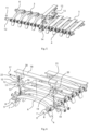
FIGURE 4 illustrates a track assembly in accordance with at least some embodiments of the present invention; -
FIGURE 5 is a partially exploded view of a track assembly ofFIGURE 4 ; -
FIGURE 6 is an enlarged partially exploded view of a track assembly shown inFIGURE 4 ; and -
FIGURE 7 illustrates an embodiment of a track assembly in accordance with at least some embodiments of the present invention. -
FIGURE 8 illustrates an embodiment of a track assembly in accordance with at least some embodiments of the present invention. -
Figures 9 and 10 illustrate flotation bars shown inFIGURE 8 . - In the present context, the term track assembly comprises full closed tracks and partial lengths of such tracks.
- Lengthwise direction of the track assembly is the direction of the centreline of the longitudinal direction of the track.
- Crosswise direction of the track assembly is crosswise to the lengthwise direction and same as length wise direction of the traction bars.
- Forestry machines are usually equipped with wide rubber tires. In some circumstances tracks are needed to provide better traction and climbing ability. Different types of tracks are needed for different terrain conditions. One aspect of this invention is to provide a track assembly that can be accommodated to different terrain conditions simply by attaching accessories to the basic track. These parts may be designed to provide better flotation in marshy or snowy condition or better traction when it is needed or a combination of these properties. The idea of changing the properties of the track assembly by adding or removing accessories allows high flexibility and reduces cost as only one track with suitable accessories is needed instead of two or more tracks. Another feature of the invention is use of links and locking pins for making the track chain. By locking the rotation of the pins wear can be focused on easily changeable parts. Thus maintenance and repair of the track assembly is cost effective and fast compared to earlier methods.
-
FIGURE 1 illustrates a set of tires equipped with a track assembly not in accordance with at least some embodiments of the present invention. The set of tires has in this example twotires 1, which are in forestry machines usually rubber terrain tires set on metal spokes. Thetrack assembly 2 comprisestraction bars 3 that are perpendicular to length direction of thetrack assembly 1. The purpose of thetraction bars 3 is to provide good grip on the ground or any surface the vehicle is moving. Thetraction bars 3 are usually made of steel and various manufacturers have own specifications for the shape of the bar. The length of thetraction bar 3 is set so that it extends over the width of a tire and depends thus of the dimension of the tires. Thetraction bars 3 haveguide plates 4 at each end of thetraction bar 3. The purpose of theguide plates 4 is to keep thetrack assembly 1 on thetires 1. Astires 1 don't have guide surfaces or grooves as wheels used with caterpillar tracks, the track assembly suitable for tires has to be guided at the edges of thetires 1 in order to keep thetrack assembly 2 on the tires even in difficult terrain conditions. -
FIGURES 2 and3 illustrate the same track as inFIGURE 1 but equipped withflotation bars 5, in accordance with at least some embodiments of the present invention. Theflotation bars 5 are set between twoparallel traction bars 3. Usually theflotation bars 5 are used in every gap between twoparallel traction bars 3 but it can be contemplated that smaller number of flotation bars are used and some gaps are left empty. This way the balance between traction ability and surface pressure can be adjusted, if needed or desired. - The structure of the
track assembly 2 is described in the following with reference toFIGURES 4 - 6 . Atrack assembly 2 for a terrain goingvehicle having tires 1 according to example in these figures comprises at least twotraction bars 3, each having abody 6 that is dimensioned to extend over the width of atire 1. Thebody 6 is curved so that it accommodates the outer shape of thetire 1 and provides an extension in crosswise direction of the rotation direction of the wheel. The crosswise extension and detailed shape of thebody 6 may vary according to design preferences of the manufacturer. Thebody 6 hasguide plates 4 extending from thebody 6 so that they can be set to reach over the edge of thetire 1 and to the sides of thetires 1. Theguide plates 7 are flat plates that extend in an obtuse angle from the distal ends of thebody 6 so that thebody 6 and theguide plates 4 form an opening U-shape to accommodate thetire 1. The shape of theguide plates 4 can be varied. - The
body 6 comprises a set of fourears traction bar 3 extending crosswise on relation to the length of thetraction bar 3. The ears are set on both sides of thebody 6 of thetraction bar 3 so that a pair ofears body 6. Theears inner ears 7 set opposite each other on thebody 6 andouter ears 8 set at a distance from theinner ears 7 towards the ends of thebody 6. The pair ofinner ear 7 and outer ear form aslot 9 that is directed in the lengthwise direction of thetrack assembly 1. Theguide plates 4 may be joined withinner ears 7 or made as a separate structure. - The
ears hole 10 for connecting tolinks 11 that join the traction bars 3 together to form a complete track assembly. The link11 has alink body 12 with a length and one connectinghole 13 at each opposite end of thelink body 12. Thetrack assembly 2 is constructed by connectingtraction bars 3 withlinks 11 and pins 14. Thepins 14 are set to run through a pair of one connectinghole 13 of thelink body 12 and ahole 10 ininner ear 7 andouter ear 8 of thetraction bar 3 in order to form a track chain. Thepins 14 are locked in relation to theholes 10 of theears pins 14 in theholes 14 is prevented. The locking of thepins 14 can be accomplishes simply by welding the pins to at least one of theears pin 14 in thehole 10. - The
link 11 or more precisely the link body is made of single piece of material, for example steel. Thelink 11 is very simple an easy to manufacture. As can be seen fromFIGURE 6 , thelink body 12 has twogrooves link body 12 in the middle of it length. Larger of the grooves is apositioning groove 15 and smaller isgroove 16 for lockingpin 17. This shape facilitates mounting offlotation bars 5 on thelinks 11. - The flotation bars 5 comprise a
longitudinal body part 18 and anattachment fork 19 with at least one lockinghole 20 at each end of thelongitudinal body part 18. The lockingpin 17 is set through to the locking holes 20 to connect theattachment fork 19 to thelink 11 between two parallel traction bars 3. Usually at least at least oneflotation bar 5 is placed between two parallel traction bars 3. Thelongitudinal body part 18 can have various shapes depending of what kind of traction or flotation properties are needed. The opening v-shape shown in FIGURES provides good flotation and resists clogging of the track assembly. Protruding sawtooth shapes, spikes or gripping scoops may be used in circumstances where extreme traction and gripping power is needed. The possibility to use various shapes of flotation bars high flexibility without need of several specialized tracks. - One embodiment of the
attachment fork 19 comprises twoparallel extensions 21 having the locking holes 20 at their respective ends, theextensions 21 being placed at a distance from each other so that there is agap 22 between theextensions 21. Thegap 22 is dimensioned to accommodate thelink 11 so that a link placed in thegap 22 sets between lockingpin 17 set in lockingholes 20 and bottom of thegap 22. Now the bottom of thegap 22 is on thepositioning groove 15 that holds theattachment fork 19 andwhole flotation bar 5 in place. The groove for lockingpin 16 accommodates the lockingpin 17. Instead of a groove the link may comprise a hole for the lockingpin 17. -
FIGURE 7 illustrates a track assembly wherein the links are formed of chain links 24. The ears of the traction bars 3 areloops 23 that are compatible to traditional chain links 24. The chain links 24 are set to run through the holes of theloops 23 to form a chain with the traction bars 3. Flotation bars 5 are mounted on the chain links 24 throughattachment forks 19 and secured with locking pins 17. - A method for repairing a track assembly comprises steps of removing locking of the
pins 9. For example, ifpins 9 are secured by welding, welding is cut open, whereafter removing thepins 17 and links 11can be done simply by pulling the pins off from the holes. After this, the whole track assembly is disassembled. Assembly is done in opposite order by replacing the pins and links and securing the pins so that the rotation of the pins in the holes is prevented, for example by welding. If other securing system than welding is used, disassembly and assembly may involve opening bolts and nuts, securing rings or pins and such. - The assembly in
FIGURE 8 shows a track assembly with an alternative type of aflotation bar 5. Thisflotation bar 5 comprises alongitudinal body part 18 and asimilar attachment fork 19 as described above in one end. At the opposite end to theattachment fork 19 is ahook 25 formed of ahook body 26 and anotch 27 facing towards theattachment fork 19. Thenotch 27 forms thehook 25 at the end of thehook body 26. - The idea of the
hook 25 is to simplify the structure and assembling of the track. Now thehook 25 can be placed around alink 11 or achain link 24 ina tracxk assembly and theattachment fork 19 over thelink 11 or achain link 24 on the other side of the track assembly. Only onelocking pin 17 is needed when this type of flotation bar is used. InFIGURE 8 this type offlotation bar 5 is shown in a track assembly ofFIGURE 6 but would be suitable for track assemblies ofFIGURE 7 also or other type of track assemblies having links connecting the traction bars 3. - It is to be understood that the embodiments of the invention disclosed are not limited to the particular structures, process steps, or materials disclosed herein, but are extended to equivalents thereof as would be recognized by those ordinarily skilled in the relevant arts. It should also be understood that terminology employed herein is used for the purpose of describing particular embodiments only and is not intended to be limiting.
- Reference throughout this specification to "one embodiment" or "an embodiment" means that a particular feature, structure, or characteristic described in connection with the embodiment is included in at least one embodiment of the present invention. Thus, appearances of the phrases "in one embodiment" or "in an embodiment" in various places throughout this specification are not necessarily all referring to the same embodiment.
- As used herein, a plurality of items, structural elements, compositional elements, and/or materials may be presented in a common list for convenience. However, these lists should be construed as though each member of the list is individually identified as a separate and unique member. Thus, no individual member of such list should be construed as a de facto equivalent of any other member of the same list solely based on their presentation in a common group without indications to the contrary. In addition, various embodiments and example of the present invention may be referred to herein along with alternatives for the various components thereof. It is understood that such embodiments, examples, and alternatives are not to be construed as de facto equivalents of one another, but are to be considered as separate and autonomous representations of the present invention.
- While the forgoing examples are illustrative of the principles of the present invention in one or more particular applications, it will be apparent to those of ordinary skill in the art that numerous modifications in form, usage and details of implementation can be made without the exercise of inventive faculty, and without departing from the principles and concepts of the invention. Accordingly, it is not intended that the invention be limited, except as by the claims set forth below.
- The verbs "to comprise" and "to include" are used in this document as open limitations that neither exclude nor require the existence of also un-recited features. The features recited in depending claims are mutually freely combinable unless otherwise explicitly stated. Furthermore, it is to be understood that the use of "a" or "an", i.e. a singular form, throughout this document does not exclude a plurality.
- The invention has industrial applicability in forestry and manufacture, maintenance and repair of equipment for forestry.
-
- 1
- tire
- 2
- track assembly
- 3
- traction bar
- 4
- guide plate
- 5
- flotation bar
- 6
- body
- 7
- inner ear
- 8
- outer ear
- 9
- slot
- 10
- hole
- 11
- link
- 12
- link body
- 13
- connecting hole
- 14
- pin
- 15
- positioning groove
- 16
- groove for locking pin
- 17
- locking pin
- 18
- longitudinal body part
- 19
- attachment fork
- 20
- locking hole
- 21
- extension
- 22
- gap
- 23
- loop
- 24
- chain link
- 25
- hook
- 26
- hook body
- 27
- notch
-
Claims (10)
- A track assembly (2) for a terrain going vehicle having tires (1), the track assembly (2) comprising:- at least two traction bars (3), each having a body (6) that is dimensioned to extend over the width of a tire (1) and guide plates (4) extending from the body (6) so that they can be set to reach over the edge of the tire (1) and to the sides of the tires (1),- ears (7, 8) at each end of each traction bar (3), extending crosswise on relation to the length of the traction bar (3) and on both sides of the body (3) of the traction bar (3), the ears (7, 8) having each at least one hole (10),- at least one link (11) having a link body (12) with a length and one connecting hole (13) at each opposite end of the link body (12), and- pins (14) set to run through a pair of one hole of the link body (12) and at least one hole of an ear (7, 8) of the traction bar (3) in order to form a chain, wherein the pins (14) are locked in relation to the holes (10) of the ears (7, 8) so that rotation of the pins (14) in the holes (10) is prevented,characterized of- at least one flotation bar (5) placed between two parallel traction bars (3), the flotation bar (5) having a longitudinal body part (18) and an attachment fork (19) with at least one locking hole (20) at least at one end of the longitudinal body part (18) and an attachment element in the opposite end of the longitudinal body part (18), and- a locking pin (17) set through at least one of of the locking holes (20) and connecting the attachment fork (19) to the link (11) between the two parallel traction bars (3).
- A track assembly (2) according to the claim 1, wherein the link body (12) is made of single piece of material.
- A track assembly (2) according to the claim 1, wherein the flotation bar (5) has a longitudinal body part (18) and an attachment fork (19) with at least one locking hole (20) at each end of the longitudinal body part (18), and a locking pin (17) set through each of the locking holes (20) and connecting the attachment fork (19) to the link (11) between the two parallel traction bars (3).
- A track assembly (2) according to the claim 1, wherein the flotation bar (5) has a longitudinal body (18) and an attachment fork (19) with at least one locking hole (20) at one end of the longitudinal body part (18), and a hook (25) at the opposite end of the longitudinal body part (18), and a locking pin (17) set through each of the locking holes (20) and connecting the attachment fork (19) to the link (11) between the two parallel traction bars (3).
- A track assembly (2) according to claim 1 or 3, wherein the attachment fork (19) comprises two parallel extensions (21) having the locking holes (20) at their respective ends, the extensions (21) being placed at a distance from each other so that there is a gap (22) between the extensions (21) and the gap (22) is dimensioned to accommodate the link (11) so that a link (11) placed in the gap (22) sets between locking pin (17) set in locking holes (20) and bottom of the gap (22).
- A track assembly (2) according to claim 5, wherein the link body (12) comprises a groove (16) for the locking pin (17).
- A track assembly (2) according to claim 5, wherein the link body (12) comprises a hole for the locking pin (17).
- A track assembly (2) according to the claim 4, wherein the hook (25) comprises a hook body (26) extending from one end of a longitudinal body part (18) and a notch (27) facing the opposite end of the longitudinal body part (18) and forming the hook (25).
- A track assembly (2) for a terrain going vehicle having tires (1), the track assembly (2) comprising:- at least two traction bars (3), each having a body (6) that is dimensioned to extend over the width of the tire (1) and have guide plates (4) extending from the body (6) so that they can be set to reach over the edge of the tire (1) and to the sides of the tires (1),- ears (7, 8) at each end of each traction bar (3), extending crosswise on relation to the length of the traction bar (39 and on both sides of the body (6) of the traction bar (3), the ears (7, 8) having each at least one hole (10),- at least one link (11) formed of a chain link (24) and set to run through the holes (10) of the ears (7, 8) to form a chain with the traction bars (3), characterized of- at least one flotation bar (5) placed between two parallel traction bars (3), the flotation bar (5) having a longitudinal body part (18) and an attachment fork (19) with at least one locking hole (20) at each end of the longitudinal body part (18), and- a locking pin (17) set through to each of the locking holes (20) and connecting the attachment fork (19) to the chain link (24) between the two parallel traction bars (3).
- A track assembly (2) according to claim 9 wherein the attachment fork (19) comprises two parallel extensions (21) having the locking holes (20) at their respective ends, the extensions (21) being placed at a distance from each other so that there is a gap (22) between the extensions (21) and gap (22) is dimensioned to accommodate the chain link (24) so that the chain link (22) placed in the gap (22) sets between locking pin (17) set in locking holes (20) and bottom of the gap (22).
Priority Applications (1)
| Application Number | Priority Date | Filing Date | Title |
|---|---|---|---|
| EP20197761.8A EP3789277B1 (en) | 2017-07-21 | 2017-09-26 | Track assemblies for terrain going vehicles and method for repairing the tracks |
Applications Claiming Priority (3)
| Application Number | Priority Date | Filing Date | Title |
|---|---|---|---|
| FIU20174189U FI11847U1 (en) | 2017-07-21 | 2017-07-21 | Tire assembly for off-road vehicles |
| PCT/FI2017/050551 WO2019016430A1 (en) | 2017-07-21 | 2017-07-21 | Track assemblies for terrain going vehicles and method for repairing the tracks |
| PCT/FI2017/050676 WO2019016431A1 (en) | 2017-07-21 | 2017-09-26 | Track assemblies for terrain going vehicles and method for repairing the tracks |
Related Child Applications (2)
| Application Number | Title | Priority Date | Filing Date |
|---|---|---|---|
| EP20197761.8A Division-Into EP3789277B1 (en) | 2017-07-21 | 2017-09-26 | Track assemblies for terrain going vehicles and method for repairing the tracks |
| EP20197761.8A Division EP3789277B1 (en) | 2017-07-21 | 2017-09-26 | Track assemblies for terrain going vehicles and method for repairing the tracks |
Publications (4)
| Publication Number | Publication Date |
|---|---|
| EP3655312A1 EP3655312A1 (en) | 2020-05-27 |
| EP3655312A4 EP3655312A4 (en) | 2021-04-21 |
| EP3655312B1 true EP3655312B1 (en) | 2025-07-09 |
| EP3655312C0 EP3655312C0 (en) | 2025-07-09 |
Family
ID=65015630
Family Applications (2)
| Application Number | Title | Priority Date | Filing Date |
|---|---|---|---|
| EP20197761.8A Active EP3789277B1 (en) | 2017-07-21 | 2017-09-26 | Track assemblies for terrain going vehicles and method for repairing the tracks |
| EP17918117.7A Active EP3655312B1 (en) | 2017-07-21 | 2017-09-26 | Track assemblies for terrain going vehicles and method for repairing the tracks |
Family Applications Before (1)
| Application Number | Title | Priority Date | Filing Date |
|---|---|---|---|
| EP20197761.8A Active EP3789277B1 (en) | 2017-07-21 | 2017-09-26 | Track assemblies for terrain going vehicles and method for repairing the tracks |
Country Status (6)
| Country | Link |
|---|---|
| US (1) | US11524730B2 (en) |
| EP (2) | EP3789277B1 (en) |
| BR (1) | BR112020001267A2 (en) |
| CA (1) | CA3078448A1 (en) |
| RU (1) | RU2020107538A (en) |
| WO (1) | WO2019016431A1 (en) |
Families Citing this family (7)
| Publication number | Priority date | Publication date | Assignee | Title |
|---|---|---|---|---|
| US11702158B2 (en) | 2020-05-27 | 2023-07-18 | Epiroc Drilling Solutions, Llc | Track shoe and track assembly for tracked vehicles |
| CN111634163A (en) * | 2020-05-27 | 2020-09-08 | 秦皇岛市大象轮胎有限公司 | Tire anti-skid chain mounting device |
| DE102020133201A1 (en) | 2020-12-11 | 2022-06-15 | Rud Ketten Rieger & Dietz Gmbh U. Co. Kg | Slat conveyor with deferred flotation plate |
| CN115610540A (en) * | 2022-06-20 | 2023-01-17 | 吉林大学 | Track assembly and device with same |
| USD1046926S1 (en) * | 2022-06-23 | 2024-10-15 | Olofsfors Ab | Crossbar member to be included in a track belt for vehicle tires |
| EP4461627A1 (en) * | 2023-05-11 | 2024-11-13 | Nordic Traction Oy | Forest machine track |
| EP4703243A1 (en) * | 2024-08-28 | 2026-03-04 | Nordic Traction Oy | Forest machine track |
Family Cites Families (26)
| Publication number | Priority date | Publication date | Assignee | Title |
|---|---|---|---|---|
| US1942338A (en) * | 1931-12-04 | 1934-01-02 | Kennedy Donald Stuart | Traction belt |
| US2726904A (en) | 1953-10-15 | 1955-12-13 | Mieczyslaw G Bekker | Endless track |
| US3738715A (en) * | 1971-05-24 | 1973-06-12 | Overum Bruk Ab | Cleat plate structures for caterpillar belts |
| US4089565A (en) * | 1975-11-03 | 1978-05-16 | Loegering George A | Removable track structure for wheeled vehicles |
| US5429429A (en) * | 1992-08-28 | 1995-07-04 | Loegering; George A. | Track bolster for a track section of a removable flexible track belt |
| JP3325422B2 (en) | 1994-06-13 | 2002-09-17 | 三菱製鋼株式会社 | Iron track with rubber pad |
| US5951124A (en) * | 1997-12-10 | 1999-09-14 | Hoffart; Ronald J. | Self-cleaning track |
| SE513659C2 (en) * | 1998-01-07 | 2000-10-16 | Olofsfors Ab | belt assembly |
| US6203127B1 (en) | 1999-11-04 | 2001-03-20 | Henry Chapman | Track assembly for a wheeled vehicle |
| US6447077B1 (en) * | 2000-08-08 | 2002-09-10 | Loegering Mfg. Inc. | Lift link flexible track |
| CN1527775A (en) | 2000-12-22 | 2004-09-08 | ���ɭ��J�������� | Low ground pressure snow chain for skid steer loaders and other construction machines |
| US6464309B2 (en) | 2000-12-22 | 2002-10-15 | Richardson J. Doyle | Low ground pressure tire chains for skid-steer loaders and other construction machinery |
| CA2395168C (en) | 2002-07-25 | 2008-09-16 | Soucy International Inc. | Tire engaging track |
| US20060232130A1 (en) * | 2005-04-19 | 2006-10-19 | Christian Hansen | Traction apparatus for wheeled vehicles |
| FI121111B (en) | 2007-09-25 | 2010-07-15 | Ponsse Oyj | Arrangement on forest machine and forest machine |
| US9630663B1 (en) * | 2010-01-15 | 2017-04-25 | Ward Equipment, LLC | Track system and method for use with rubber tire equipment |
| BR112012028845B1 (en) | 2010-05-12 | 2020-06-30 | Olofsfors Ab | belt section with two lateral support members and method for producing a support member for such a belt section |
| RU128596U1 (en) | 2012-11-28 | 2013-05-27 | Андрей Юрьевич Козин | VEHICLE CRAWLER CHAIN |
| RU133087U1 (en) | 2013-04-01 | 2013-10-10 | Андрей Юрьевич Козин | CRAWLER CHAIN OF WHEEL VEHICLE |
| SE537571C2 (en) | 2013-10-10 | 2015-06-23 | Komatsu Forest Ab | Apparatus for adjusting the ground pressure of an off-road motor vehicle and an off-road motor vehicle equipped with such a device |
| DE202014103179U1 (en) | 2014-07-10 | 2014-07-30 | Erlau Ag | Plate band element for serving as a traction aid, plate-band-shaped track for twin axes |
| RU170810U1 (en) | 2016-06-15 | 2017-05-11 | Юрий Алексеевич Коваль | CRAWLER ENGINE FOR VEHICLE |
| CA3075960A1 (en) * | 2017-07-21 | 2019-01-24 | Fomatec Oy | Track assemblies for terrain going vehicles and method for repairing the tracks |
| FI20185137A1 (en) * | 2018-02-16 | 2019-08-17 | Saramoto Oy | Machine band system and method for increasing the bearing surface of a machine band of a forest machine or forest tractor |
| WO2019162558A1 (en) * | 2018-02-23 | 2019-08-29 | Fomatec Oy | Track assembly for terrain going vehicles and a link for the track assembly |
| FI20185710A1 (en) * | 2018-08-29 | 2020-03-01 | Fomatec Oy | Wheel track and method for manufacturing the same |
-
2017
- 2017-09-26 BR BR112020001267-0A patent/BR112020001267A2/en not_active Application Discontinuation
- 2017-09-26 CA CA3078448A patent/CA3078448A1/en active Pending
- 2017-09-26 RU RU2020107538A patent/RU2020107538A/en not_active Application Discontinuation
- 2017-09-26 EP EP20197761.8A patent/EP3789277B1/en active Active
- 2017-09-26 EP EP17918117.7A patent/EP3655312B1/en active Active
- 2017-09-26 WO PCT/FI2017/050676 patent/WO2019016431A1/en not_active Ceased
- 2017-09-26 US US16/632,551 patent/US11524730B2/en active Active
Also Published As
| Publication number | Publication date |
|---|---|
| RU2020107538A3 (en) | 2021-08-23 |
| RU2020107538A (en) | 2021-08-23 |
| WO2019016431A1 (en) | 2019-01-24 |
| CA3078448A1 (en) | 2019-01-24 |
| EP3789277C0 (en) | 2025-10-15 |
| US11524730B2 (en) | 2022-12-13 |
| US20200156719A1 (en) | 2020-05-21 |
| EP3655312C0 (en) | 2025-07-09 |
| BR112020001267A2 (en) | 2020-07-21 |
| EP3655312A1 (en) | 2020-05-27 |
| EP3655312A4 (en) | 2021-04-21 |
| EP3789277A1 (en) | 2021-03-10 |
| EP3789277B1 (en) | 2025-10-15 |
Similar Documents
| Publication | Publication Date | Title |
|---|---|---|
| EP3655312B1 (en) | Track assemblies for terrain going vehicles and method for repairing the tracks | |
| WO2019016430A1 (en) | Track assemblies for terrain going vehicles and method for repairing the tracks | |
| EP1984233B1 (en) | Tracks for track laying vehicles and vehicles carrying such tracks | |
| CN110603210B (en) | Drive shafts and sprockets for chain conveyors | |
| US20100072813A1 (en) | Crawler Tracks and Idlers for Crawler Tracks | |
| WO2019162558A1 (en) | Track assembly for terrain going vehicles and a link for the track assembly | |
| EP3680154B1 (en) | Undercarriage clamping master track link | |
| EP1880932A1 (en) | Rubberized segmented track | |
| KR20120106884A (en) | Tyre anti-skid device | |
| AU2020425311B2 (en) | Track shoe with wear resistant grouser | |
| AU2019320843B2 (en) | Flexible plate for endless tracks used on large machines and method for manufacturing the flexible plate | |
| CA2141239C (en) | Track device having wheel widening effect | |
| FI20185710A1 (en) | Wheel track and method for manufacturing the same | |
| US20060232130A1 (en) | Traction apparatus for wheeled vehicles | |
| US7658455B2 (en) | Traction enhancement device | |
| EP1864891A1 (en) | Track shoe assembly for tracked vehicle | |
| JP3483674B2 (en) | Elastic crawler | |
| US20050067897A1 (en) | Vehicle track chain and link therefor | |
| EP4703243A1 (en) | Forest machine track | |
| CA2433911C (en) | Endless loop track for a track vehicle | |
| EP1951566B1 (en) | Track chain assembly | |
| AU2004100594A4 (en) | Plastic track for a skid steer loader | |
| US6817682B1 (en) | Skid steer track | |
| WO2025171473A1 (en) | Repair assembly for a damaged elastomeric endless track | |
| WO2010089625A1 (en) | Traction enhancement device |
Legal Events
| Date | Code | Title | Description |
|---|---|---|---|
| STAA | Information on the status of an ep patent application or granted ep patent |
Free format text: STATUS: THE INTERNATIONAL PUBLICATION HAS BEEN MADE |
|
| PUAI | Public reference made under article 153(3) epc to a published international application that has entered the european phase |
Free format text: ORIGINAL CODE: 0009012 |
|
| STAA | Information on the status of an ep patent application or granted ep patent |
Free format text: STATUS: REQUEST FOR EXAMINATION WAS MADE |
|
| 17P | Request for examination filed |
Effective date: 20200220 |
|
| AK | Designated contracting states |
Kind code of ref document: A1 Designated state(s): AL AT BE BG CH CY CZ DE DK EE ES FI FR GB GR HR HU IE IS IT LI LT LU LV MC MK MT NL NO PL PT RO RS SE SI SK SM TR |
|
| AX | Request for extension of the european patent |
Extension state: BA ME |
|
| DAV | Request for validation of the european patent (deleted) | ||
| DAX | Request for extension of the european patent (deleted) | ||
| A4 | Supplementary search report drawn up and despatched |
Effective date: 20210322 |
|
| RIC1 | Information provided on ipc code assigned before grant |
Ipc: B62D 55/205 20060101AFI20210316BHEP Ipc: B62D 55/28 20060101ALI20210316BHEP Ipc: B62D 55/04 20060101ALI20210316BHEP Ipc: B60C 27/20 20060101ALI20210316BHEP |
|
| 19U | Interruption of proceedings before grant |
Effective date: 20210924 |
|
| 19W | Proceedings resumed before grant after interruption of proceedings |
Effective date: 20221201 |
|
| RAP3 | Party data changed (applicant data changed or rights of an application transferred) |
Owner name: RUD KETTEN RIEGER & DIETZ GMBH U. CO. KG |
|
| GRAP | Despatch of communication of intention to grant a patent |
Free format text: ORIGINAL CODE: EPIDOSNIGR1 |
|
| STAA | Information on the status of an ep patent application or granted ep patent |
Free format text: STATUS: GRANT OF PATENT IS INTENDED |
|
| INTG | Intention to grant announced |
Effective date: 20250314 |
|
| GRAS | Grant fee paid |
Free format text: ORIGINAL CODE: EPIDOSNIGR3 |
|
| GRAA | (expected) grant |
Free format text: ORIGINAL CODE: 0009210 |
|
| STAA | Information on the status of an ep patent application or granted ep patent |
Free format text: STATUS: THE PATENT HAS BEEN GRANTED |
|
| AK | Designated contracting states |
Kind code of ref document: B1 Designated state(s): AL AT BE BG CH CY CZ DE DK EE ES FI FR GB GR HR HU IE IS IT LI LT LU LV MC MK MT NL NO PL PT RO RS SE SI SK SM TR |
|
| REG | Reference to a national code |
Ref country code: GB Ref legal event code: FG4D |
|
| REG | Reference to a national code |
Ref country code: CH Ref legal event code: EP |
|
| REG | Reference to a national code |
Ref country code: IE Ref legal event code: FG4D |
|
| REG | Reference to a national code |
Ref country code: DE Ref legal event code: R096 Ref document number: 602017090525 Country of ref document: DE |
|
| U01 | Request for unitary effect filed |
Effective date: 20250721 |
|
| U07 | Unitary effect registered |
Designated state(s): AT BE BG DE DK EE FI FR IT LT LU LV MT NL PT RO SE SI Effective date: 20250728 |
|
| PGFP | Annual fee paid to national office [announced via postgrant information from national office to epo] |
Ref country code: NO Payment date: 20250923 Year of fee payment: 9 |
|
| PGFP | Annual fee paid to national office [announced via postgrant information from national office to epo] |
Ref country code: TR Payment date: 20250925 Year of fee payment: 9 |
|
| U20 | Renewal fee for the european patent with unitary effect paid |
Year of fee payment: 9 Effective date: 20251001 |
|
| PG25 | Lapsed in a contracting state [announced via postgrant information from national office to epo] |
Ref country code: IS Free format text: LAPSE BECAUSE OF FAILURE TO SUBMIT A TRANSLATION OF THE DESCRIPTION OR TO PAY THE FEE WITHIN THE PRESCRIBED TIME-LIMIT Effective date: 20251109 |
|
| PG25 | Lapsed in a contracting state [announced via postgrant information from national office to epo] |
Ref country code: HR Free format text: LAPSE BECAUSE OF FAILURE TO SUBMIT A TRANSLATION OF THE DESCRIPTION OR TO PAY THE FEE WITHIN THE PRESCRIBED TIME-LIMIT Effective date: 20250709 |
|
| PG25 | Lapsed in a contracting state [announced via postgrant information from national office to epo] |
Ref country code: GR Free format text: LAPSE BECAUSE OF FAILURE TO SUBMIT A TRANSLATION OF THE DESCRIPTION OR TO PAY THE FEE WITHIN THE PRESCRIBED TIME-LIMIT Effective date: 20251010 |
|
| PG25 | Lapsed in a contracting state [announced via postgrant information from national office to epo] |
Ref country code: PL Free format text: LAPSE BECAUSE OF FAILURE TO SUBMIT A TRANSLATION OF THE DESCRIPTION OR TO PAY THE FEE WITHIN THE PRESCRIBED TIME-LIMIT Effective date: 20250709 |
|
| PG25 | Lapsed in a contracting state [announced via postgrant information from national office to epo] |
Ref country code: RS Free format text: LAPSE BECAUSE OF FAILURE TO SUBMIT A TRANSLATION OF THE DESCRIPTION OR TO PAY THE FEE WITHIN THE PRESCRIBED TIME-LIMIT Effective date: 20251009 |
|
| PG25 | Lapsed in a contracting state [announced via postgrant information from national office to epo] |
Ref country code: ES Free format text: LAPSE BECAUSE OF FAILURE TO SUBMIT A TRANSLATION OF THE DESCRIPTION OR TO PAY THE FEE WITHIN THE PRESCRIBED TIME-LIMIT Effective date: 20250709 |
|
| PG25 | Lapsed in a contracting state [announced via postgrant information from national office to epo] |
Ref country code: SM Free format text: LAPSE BECAUSE OF FAILURE TO SUBMIT A TRANSLATION OF THE DESCRIPTION OR TO PAY THE FEE WITHIN THE PRESCRIBED TIME-LIMIT Effective date: 20250709 |
|
| PG25 | Lapsed in a contracting state [announced via postgrant information from national office to epo] |
Ref country code: CZ Free format text: LAPSE BECAUSE OF FAILURE TO SUBMIT A TRANSLATION OF THE DESCRIPTION OR TO PAY THE FEE WITHIN THE PRESCRIBED TIME-LIMIT Effective date: 20250709 |
|
| PG25 | Lapsed in a contracting state [announced via postgrant information from national office to epo] |
Ref country code: SK Free format text: LAPSE BECAUSE OF FAILURE TO SUBMIT A TRANSLATION OF THE DESCRIPTION OR TO PAY THE FEE WITHIN THE PRESCRIBED TIME-LIMIT Effective date: 20250709 |