EP3655129B1 - Dewatering systems and methods - Google Patents
Dewatering systems and methods Download PDFInfo
- Publication number
- EP3655129B1 EP3655129B1 EP18755350.8A EP18755350A EP3655129B1 EP 3655129 B1 EP3655129 B1 EP 3655129B1 EP 18755350 A EP18755350 A EP 18755350A EP 3655129 B1 EP3655129 B1 EP 3655129B1
- Authority
- EP
- European Patent Office
- Prior art keywords
- influent
- sensor
- operatively connected
- filtration assembly
- solids
- Prior art date
- Legal status (The legal status is an assumption and is not a legal conclusion. Google has not performed a legal analysis and makes no representation as to the accuracy of the status listed.)
- Active
Links
Images


Classifications
-
- C—CHEMISTRY; METALLURGY
- C02—TREATMENT OF WATER, WASTE WATER, SEWAGE, OR SLUDGE
- C02F—TREATMENT OF WATER, WASTE WATER, SEWAGE, OR SLUDGE
- C02F11/00—Treatment of sludge; Devices therefor
- C02F11/12—Treatment of sludge; Devices therefor by de-watering, drying or thickening
- C02F11/121—Treatment of sludge; Devices therefor by de-watering, drying or thickening by mechanical de-watering
-
- B—PERFORMING OPERATIONS; TRANSPORTING
- B01—PHYSICAL OR CHEMICAL PROCESSES OR APPARATUS IN GENERAL
- B01D—SEPARATION
- B01D29/00—Filters with filtering elements stationary during filtration, e.g. pressure or suction filters, not covered by groups B01D24/00 - B01D27/00; Filtering elements therefor
- B01D29/11—Filters with filtering elements stationary during filtration, e.g. pressure or suction filters, not covered by groups B01D24/00 - B01D27/00; Filtering elements therefor with bag, cage, hose, tube, sleeve or like filtering elements
- B01D29/31—Self-supporting filtering elements
- B01D29/35—Self-supporting filtering elements arranged for outward flow filtration
- B01D29/356—Self-supporting filtering elements arranged for outward flow filtration open-ended, the arrival of the mixture to be filtered and the discharge of the concentrated mixture are situated on both opposite sides of the filtering element
-
- B—PERFORMING OPERATIONS; TRANSPORTING
- B01—PHYSICAL OR CHEMICAL PROCESSES OR APPARATUS IN GENERAL
- B01D—SEPARATION
- B01D29/00—Filters with filtering elements stationary during filtration, e.g. pressure or suction filters, not covered by groups B01D24/00 - B01D27/00; Filtering elements therefor
- B01D29/60—Filters with filtering elements stationary during filtration, e.g. pressure or suction filters, not covered by groups B01D24/00 - B01D27/00; Filtering elements therefor integrally combined with devices for controlling the filtration
-
- B—PERFORMING OPERATIONS; TRANSPORTING
- B01—PHYSICAL OR CHEMICAL PROCESSES OR APPARATUS IN GENERAL
- B01D—SEPARATION
- B01D29/00—Filters with filtering elements stationary during filtration, e.g. pressure or suction filters, not covered by groups B01D24/00 - B01D27/00; Filtering elements therefor
- B01D29/76—Handling the filter cake in the filter for purposes other than for regenerating
- B01D29/80—Handling the filter cake in the filter for purposes other than for regenerating for drying
- B01D29/82—Handling the filter cake in the filter for purposes other than for regenerating for drying by compression
- B01D29/828—Handling the filter cake in the filter for purposes other than for regenerating for drying by compression using screws
-
- B—PERFORMING OPERATIONS; TRANSPORTING
- B01—PHYSICAL OR CHEMICAL PROCESSES OR APPARATUS IN GENERAL
- B01D—SEPARATION
- B01D33/00—Filters with filtering elements which move during the filtering operation
- B01D33/29—Filters with filtering elements which move during the filtering operation the movement of the filter elements being a combination of movements
-
- B—PERFORMING OPERATIONS; TRANSPORTING
- B01—PHYSICAL OR CHEMICAL PROCESSES OR APPARATUS IN GENERAL
- B01D—SEPARATION
- B01D33/00—Filters with filtering elements which move during the filtering operation
- B01D33/44—Regenerating the filter material in the filter
- B01D33/46—Regenerating the filter material in the filter by scrapers, brushes nozzles or the like acting on the cake-side of the filtering element
- B01D33/466—Regenerating the filter material in the filter by scrapers, brushes nozzles or the like acting on the cake-side of the filtering element scrapers
-
- B—PERFORMING OPERATIONS; TRANSPORTING
- B30—PRESSES
- B30B—PRESSES IN GENERAL
- B30B9/00—Presses specially adapted for particular purposes
- B30B9/02—Presses specially adapted for particular purposes for squeezing-out liquid from liquid-containing material, e.g. juice from fruits, oil from oil-containing material
- B30B9/12—Presses specially adapted for particular purposes for squeezing-out liquid from liquid-containing material, e.g. juice from fruits, oil from oil-containing material using pressing worms or screws co-operating with a permeable casing
- B30B9/125—Control arrangements
-
- B—PERFORMING OPERATIONS; TRANSPORTING
- B30—PRESSES
- B30B—PRESSES IN GENERAL
- B30B9/00—Presses specially adapted for particular purposes
- B30B9/02—Presses specially adapted for particular purposes for squeezing-out liquid from liquid-containing material, e.g. juice from fruits, oil from oil-containing material
- B30B9/26—Permeable casings or strainers
-
- C—CHEMISTRY; METALLURGY
- C02—TREATMENT OF WATER, WASTE WATER, SEWAGE, OR SLUDGE
- C02F—TREATMENT OF WATER, WASTE WATER, SEWAGE, OR SLUDGE
- C02F11/00—Treatment of sludge; Devices therefor
- C02F11/12—Treatment of sludge; Devices therefor by de-watering, drying or thickening
- C02F11/121—Treatment of sludge; Devices therefor by de-watering, drying or thickening by mechanical de-watering
- C02F11/125—Treatment of sludge; Devices therefor by de-watering, drying or thickening by mechanical de-watering using screw filters
-
- C—CHEMISTRY; METALLURGY
- C02—TREATMENT OF WATER, WASTE WATER, SEWAGE, OR SLUDGE
- C02F—TREATMENT OF WATER, WASTE WATER, SEWAGE, OR SLUDGE
- C02F1/00—Treatment of water, waste water, or sewage
- C02F1/52—Treatment of water, waste water, or sewage by flocculation or precipitation of suspended impurities
- C02F1/5209—Regulation methods for flocculation or precipitation
-
- C—CHEMISTRY; METALLURGY
- C02—TREATMENT OF WATER, WASTE WATER, SEWAGE, OR SLUDGE
- C02F—TREATMENT OF WATER, WASTE WATER, SEWAGE, OR SLUDGE
- C02F11/00—Treatment of sludge; Devices therefor
- C02F11/12—Treatment of sludge; Devices therefor by de-watering, drying or thickening
- C02F11/14—Treatment of sludge; Devices therefor by de-watering, drying or thickening with addition of chemical agents
-
- C—CHEMISTRY; METALLURGY
- C02—TREATMENT OF WATER, WASTE WATER, SEWAGE, OR SLUDGE
- C02F—TREATMENT OF WATER, WASTE WATER, SEWAGE, OR SLUDGE
- C02F2209/00—Controlling or monitoring parameters in water treatment
- C02F2209/001—Upstream control, i.e. monitoring for predictive control
-
- C—CHEMISTRY; METALLURGY
- C02—TREATMENT OF WATER, WASTE WATER, SEWAGE, OR SLUDGE
- C02F—TREATMENT OF WATER, WASTE WATER, SEWAGE, OR SLUDGE
- C02F2209/00—Controlling or monitoring parameters in water treatment
- C02F2209/003—Downstream control, i.e. outlet monitoring, e.g. to check the treating agents, such as halogens or ozone, leaving the process
-
- C—CHEMISTRY; METALLURGY
- C02—TREATMENT OF WATER, WASTE WATER, SEWAGE, OR SLUDGE
- C02F—TREATMENT OF WATER, WASTE WATER, SEWAGE, OR SLUDGE
- C02F2209/00—Controlling or monitoring parameters in water treatment
- C02F2209/005—Processes using a programmable logic controller [PLC]
-
- C—CHEMISTRY; METALLURGY
- C02—TREATMENT OF WATER, WASTE WATER, SEWAGE, OR SLUDGE
- C02F—TREATMENT OF WATER, WASTE WATER, SEWAGE, OR SLUDGE
- C02F2209/00—Controlling or monitoring parameters in water treatment
- C02F2209/03—Pressure
-
- C—CHEMISTRY; METALLURGY
- C02—TREATMENT OF WATER, WASTE WATER, SEWAGE, OR SLUDGE
- C02F—TREATMENT OF WATER, WASTE WATER, SEWAGE, OR SLUDGE
- C02F2209/00—Controlling or monitoring parameters in water treatment
- C02F2209/10—Solids, e.g. total solids [TS], total suspended solids [TSS] or volatile solids [VS]
-
- C—CHEMISTRY; METALLURGY
- C02—TREATMENT OF WATER, WASTE WATER, SEWAGE, OR SLUDGE
- C02F—TREATMENT OF WATER, WASTE WATER, SEWAGE, OR SLUDGE
- C02F2209/00—Controlling or monitoring parameters in water treatment
- C02F2209/11—Turbidity
-
- C—CHEMISTRY; METALLURGY
- C02—TREATMENT OF WATER, WASTE WATER, SEWAGE, OR SLUDGE
- C02F—TREATMENT OF WATER, WASTE WATER, SEWAGE, OR SLUDGE
- C02F2209/00—Controlling or monitoring parameters in water treatment
- C02F2209/40—Liquid flow rate
-
- C—CHEMISTRY; METALLURGY
- C02—TREATMENT OF WATER, WASTE WATER, SEWAGE, OR SLUDGE
- C02F—TREATMENT OF WATER, WASTE WATER, SEWAGE, OR SLUDGE
- C02F2209/00—Controlling or monitoring parameters in water treatment
- C02F2209/42—Liquid level
Definitions
- the invention relates to dewatering systems, and more particularly to sludge dewatering systems.
- a dewatering system for wastewater acts to separate solids and liquids from one another in order to prepare both the solids and liquids for further processing.
- Dewatering apparatuses typically include a mechanical or mechanical/electrical filtration system that drives influent through a filter to separate the solids and liquids from one another.
- These mechanical or mechanical/electrical filtration systems include, but are not limited to screw presses, centrifuges, ring presses, filter presses, plate and frame presses, rotary presses, or the like.
- JP 2014-226619 A discloses a multiple plate type screw press dehydrator with a sensor attached to a hole of a holed annular plate for detecting the state of a sludge.
- US 6,615,710 B1 , JP 2008-229678 A and JP 2004-090049 A disclose further screw press dewatering systems with sensors upstream and downstream the filtration assembly.
- the present invention is directed to a screw press dewatering system for removing solids from an influent, as defined in the independent claim 1.
- a July 5, 2024 preferred embodiment is defined in the dependent claim 2.
- the dewatering system includes a filtration assembly and a feed pipe upstream thereof.
- the dewatering system includes a solids receptacle downstream of the filtration assembly, and an effluent collector adjacent to the filtration assembly and in fluid communication with the filtration assembly.
- the dewatering system includes an influent storage receptacle upstream from the filtration assembly and downstream of the feed pipe.
- the dewatering system also includes a conduit upstream from the filtration assembly and downstream from the feed pipe, extending between an outlet of the influent storage receptacle and an inlet of filtration assembly.
- the dewatering system includes sensors to sense a characteristic of an influent, an effluent and a solid.
- a control system is operatively connected to the sensors to receive sensor signals therefrom and to generate an adjustment signal based on the sensor signals to improve the efficiency of the dewatering system.
- the dewatering system can include a feed pump, a valve, and/or a weir operatively connected to the feed pipe to draw influent into the influent storage receptacle.
- a first sensor is operatively connected to the conduit.
- the sensor is a light sensor used to measure an amount of suspended solids in the influent, a degree of homogeneity in the influent, a degree of flocculation of the solids in the influent, and/or a size of flocculated solid nodules in the influent.
- a second sensor is operatively connected to the feed pipe and measures a density, an amount of suspended solids, turbidity, and/or a flow rate of an influent.
- a third sensor is operatively connected to the influent storage receptacle.
- the sensor is a level sensor, a turbidity sensor and/or a reflectivity sensor.
- a fourth sensor is operatively connected to the filtration assembly to measure either pressure and/or strain.
- the filtration assembly includes a drum, an auger positioned within the drum, and a series of spaced apart plates.
- the fourth sensor measures pressure and/or strain of the drum, one or more of the spaced apart plates or the auger.
- a fifth sensor is operatively connected to the solids receptacle.
- the fifth sensor measures solid content, moisture content, density, and/or permissivity to energy of solids in the solids receptacle.
- a sixth sensor is operatively connected between the filtration assembly and the solids receptacle.
- the sixth sensor measures solid content, moisture content, density, and/or permissivity to energy.
- a seventh sensor is operatively connected to the effluent collector.
- the seventh sensor measures an amount of suspended solids, turbidity, color, density, and/or interruption of a light or laser beam in the effluent discharged from the filtration assembly.
- the dewatering system includes a motor operatively connected to the filtration assembly.
- An eighth sensor is operatively connected to the motor. The eighth sensor measures torque, amperage draw, rotational speed, temperature and/or power factor of the motor.
- system can include multiple additional sensors in one embodiment such that additional sensors can be positioned in more than one of the locations described above.
- the present invention is directed to a method for adjusting the previously described dewatering system that removes liquid from an influent.
- the method according to the invention is defined in the independent claim 3.
- Preferred embodiments are defined in the dependent claims 4-7.
- the method includes determining a characteristic of at least one of an influent, an effluent or a solid in a dewatering system.
- the method includes adjusting an operating parameter of the dewatering system based on the characteristic of at least one of the influent, the effluent or the solid in the dewatering system.
- adjusting a chemical dosing provided to the dewatering system and/or adjusting an influent feed rate from an influent storage receptacle to the filtration assembly downstream from the influent storage receptacle.
- Adjusting the operating parameter of the dewatering system can also include adjusting the speed of an element in a filtration assembly downstream from an influent storage receptacle.
- Adjusting the operating parameter of the dewatering system can include adjusting the feed rate of an influent to the dewatering system through an influent feed pipe by adjusting (i) the speed of a feed pump operatively connected to the influent feed pipe, (ii) the opening or closing of a valve operatively connected to the influent feed pipe, and/or (iii) the raising or lowering of a weir operatively connected to the influent feed pipe.
- the method determines the characteristic of an influent includes receiving a signal from a first, second or third sensor operatively connected to an influent feed pipe, an influent storage receptacle, and a conduit.
- the method includes determining a characteristic of a filtration assembly downstream from a conduit by receiving signal from a fourth sensor operatively connected to a filtration assembly.
- the signal can be indicative of pressure and/or strain.
- Adjusting the operating parameter of the dewatering system can include adjusting an operating parameter based on the characteristic of the filtration assembly.
- the method is determining a characteristic of the solid includes determining a characteristic of the solid in a solids receptacle downstream from the conduit.
- the fifth sensor can measure at least one of solid content, moisture content, density, or permissivity to energy, of the solid in the solids receptacle.
- Adjusting the operating parameter of the dewatering system can include adjusting the operating parameter based on the characteristic of the solid in the solids receptacle.
- the method is determining a characteristic of the influent, which includes measuring torque, amperage draw, rotational speed, temperature and/or power factor of a motor operatively connected to the dewatering system.
- FIG. 3 is a graphical illustration of an embodiment of a traditional dewatering system 10 constructed without use of the automatically adjustable control, as described in the embodiments of the present invention.
- System 10 includes an influent storage receptacle 2 having a feed pipe 4 upstream thereof, and a filtration assembly 6 downstream of influent storage receptacle 2.
- Dewatering system 10 includes a feed pump 3 operatively connected to feed pipe 4 to draw influent into influent storage receptacle 2.
- Filtration assembly 6 is in fluid communication with influent storage receptacle 2 via a conduit 8 extending between an outlet 11 of influent storage receptacle 2 and an inlet 12 of filtration assembly 6.
- a motor 22 drives filtration assembly 6.
- a solids receptacle 14 is downstream of filtration assembly 6.
- An effluent collector 16 is adjacent to and downstream of filtration assembly 6 in fluid communication with filtration assembly 6.
- a control system 20 is connected to system 10.
- a flow rate sensor 18 is connected to feed pipe 4.
- Dewatering system 100 for removing solids from an influent.
- Dewatering system 100 includes an influent storage receptacle 102 having a feed pipe 104 upstream thereof, and a filtration assembly 106 downstream of influent storage receptacle 102.
- Dewatering system 100 includes a feed pump 103 operatively connected to feed pipe 104 to draw influent into influent storage receptacle 102. It is also contemplated that a valve 105, and/or a weir 107 can be operatively connected to feed pipe 104 to draw influent into the influent storage receptacle 102.
- Filtration assembly 106 is in fluid communication with influent storage receptacle 102 via a conduit 108 extending between an outlet 110 of influent storage receptacle 102 and an inlet 112 of filtration assembly 106. It is contemplated that conduit 108 can be a hose, pipe, tube, pump, or other means of transporting the influent directly into the mechanical or chemical/mechanical filtration assembly 106. It is also contemplated that the influent can be stored in a location removed from the aforementioned filtration assembly 106. The influent may be gravity fed, pumped or otherwise conveyed into the mechanical or chemical/mechanical filtration assembly 106. Filtration assembly 106 acts to remove solids from the influent and generates a solid output and a filtrate or effluent output 117.
- a solids receptacle 114 is downstream of filtration assembly 106.
- An effluent collector 116 is adjacent to and downstream of filtration assembly 106 in fluid communication with filtration assembly 106.
- Sensors 118a-h are operatively connected to components of dewatering system 100 to sense various characteristics of the system 100. Sensors 118a-c are used to determine the quantity of liquids, solids, combined liquids and solids, or liquids and solids separately, all of which are also referred to as influent, that are awaiting filtration by filtration assembly 106.
- Sensors 118 may include but are not limited to contact or noncontact level sensors, pressure sensors, infrared, ultrasonic or microwave solids meters, turbidity or light sensors, or some combination thereof. Sensors 118a-h allow for continuous automatic control over dewatering system 100, which, in turn, assists in making the system 100 more efficient.
- a control system 120 is operatively connected to sensors 118a-h to receive at least one sensor signal therefrom and to generate an adjustment signal based on the sensor signal to improve the efficiency of the dewatering system.
- Control system 120 is also connected to one or more elements of dewatering system 100 to send the adjustment signal thereto.
- control system 120 is operatively connected to at least one of feed pump 103 and a motor 122, described below, to adjust power of motor 122 or the speed of feed pump 103.
- Control system 120 can be physically separate from filtration system 106 and receptacle 102 and can be in wireless communication with sensors 118a-h and other components of system 100.
- dewatering system 100 may accept regularly shifting flow rates from a feed pump not under control of control system 120 and compensate for them, may accept an outside requirement to increase or decrease overall system throughput and adjust system running parameters to compensate, or it may alter the feed rate to produce better performance.
- Control panel 120 will contain one Programmable Logic Controller (PLC), industrial computer, microprocessor/microcontroller device such as a Raspberry Pi or iOS, or other computing device that will be used to execute all decision-making functions to interpret the signals from sensors 118a-h, operate the dewatering system 100, and make all adjustments to operating system 100 based on the signals from sensors 118a-h.
- PLC Programmable Logic Controller
- Sensor 118a is operatively connected to the conduit 108 and is a light sensor used to measure an amount of suspended solids in the influent; this includes a turbidity sensor, an interruption of light sensor, or laser beam sensor.
- Sensor 118b is operatively connected to feed pipe 104 and measures a density, turbidity, an amount of suspended solids, and/or a flow rate.
- Sensor 118c is operatively connected to influent storage receptacle 102.
- Sensor 118c is a level sensor, turbidity sensor and/or reflectivity sensor.
- conduit 108, feed pipe 104 and storage receptacle 102 can include multiple sensors 118a, 118b, and 118c, respectively, where each measures a respective parameter, e.g. density, an amount of suspended solids, or a flow rate.
- a respective parameter e.g. density, an amount of suspended solids, or a flow rate.
- filtration assembly 106 comprises a dewatering drum 124 (e.g. cylinder) made up of an auger 126 positioned within the drum 124, and a series of spaced apart rotating and static plates, 133 and 135, respectively. Rotating and static plates 133 and 135 make up a filter screen.
- dewatering drum 124 e.g. cylinder
- Sensor 118d measures pressure or strain of drum 124, one or more of the spaced apart plates 133 and 135 and/or auger 126.
- Filtration assembly 106 also includes a pressure plate 127, and/or a support frame 129, all of which can include one or more sensors 118d. It is contemplated that in some embodiments, instead of plates 133 and 135, a fixed screen made of wire mesh, stamped or cut metal, or similar arrangement of plastic material may be substituted. A sensor similar to sensor 118d can measure pressure and/or strain of the fixed screen made of wire mesh, stamped or cut metal, and/or other similar arrangement of plastic material may be substituted.
- dewatering system includes a motor 122 operatively connected to filtration assembly 106.
- a sensor 118g is operatively connected to motor 122.
- Sensor 118g measures torque, amperage draw, rotational speed, e.g. of the motor and/or shaft, motor temperature, winding temperature, and/or power factor of motor 122.
- Sensors 118g can also measure filter mechanism rotational speed, velocity, color, ability to pass light, heat, sound or other energy through it.
- Control system 120 determines whether drum 124 can turn safely based on signals from sensors 118d and 118g, and will send an adjustment signal or modify the performance characteristics of drum 124 so that it can operate safely.
- the adjustment signal can include an automatic jam clearing command or can temporarily and/or permanently command adjustments to running parameters of motor 122 and/or other elements of the dewatering system in response to predictive indicators that a jam is likely to occur, allowing the system to continue running without interruption.
- a sensor 118e is operatively connected to solids receptacle 114 or between the solids receptacle 114 and the filtration assembly 106.
- this can be accomplished by sensor 118h that includes a device for mid-air physical capture of solids falling from filtration assembly 106 for measurement by sensor 118h. It is also contemplated that sensor 118h can conduct measurement and analysis as the solids are falling past sensor 118h from filtration assembly 106 to solids receptacle 114.
- Sensors 118e and 118h measure at least one of solid content, moisture content, density, or permissivity to energy of solids that have been removed from the influent stream by filtration system 106.
- a sensor 118f is operatively connected to the effluent collector 116.
- Sensor 118f measures, directly or indirectly, an amount of suspended solids in the filtrate/effluent, or the amount of liquid or solids removed from the influent stream.
- Sensors 118f include, but are not limited to, contact or noncontact level sensors, pressure sensors, infrared, ultrasonic or microwave solids meters, turbidity or light sensors, color sensors, or some combination thereof, effects on a secondary filtration system, or fill rate of a container or containers for filtered solids or liquids.
- dewatering system 100 will adjust running parameters via control system 120 based on the various measurements received via sensor signals from one or more sensors 118a-h and/or analysis performed on the measurements. These adjustments are made in real-time automatically to avoid potential jams, to increase processing quantity and efficiency, or the like.
- the real-time automatic adjustment of control system 120 means that shut down of system 100 tends not to be required. Adjustments to system 100 are made without requiring any input or guidance from the equipment operator or any outside sensors, control panels, facility systems or aftermarket/add-on control systems beyond control signals originating from control panel 120 and sensors 118a-h that supply inputs to control panel 120.
- These running parameters include, but are not limited to, the influent feed rate to filtration system 106, chemical dosing rate of one or more chemicals provided to system 100, speed of various mechanical filtration mechanisms, such as, drums, augers, plates, or other mechanisms. These parameters also include, but are not limited to, the mixing energy or velocity via impellers, blades or other mechanisms, amount of filtrate recycled, amount, temperature or pressure of wash water, or other parameters of operation of dewatering system 100.
- Control system 120 may include continuous process improvement or learning sub-systems that record alarm conditions causing system shutdown, such as excessive power draw or overflow of influent storage receptacle. If such an alarm condition is recorded, these sub-systems may modify operating parameters to take preventative actions that grow in magnitude as the shutdown condition is approached, and if additional system shutdowns are recorded. If the preventative action is successful, these sub-systems may experimentally reduce the magnitude of preventative actions to what is required to maintain an acceptable safety margin.
- alarm conditions causing system shutdown such as excessive power draw or overflow of influent storage receptacle. If such an alarm condition is recorded, these sub-systems may modify operating parameters to take preventative actions that grow in magnitude as the shutdown condition is approached, and if additional system shutdowns are recorded. If the preventative action is successful, these sub-systems may experimentally reduce the magnitude of preventative actions to what is required to maintain an acceptable safety margin.
- the present invention is directed to a method for adjusting a dewatering system, e.g. dewatering system 100, that removes liquid from an influent.
- the method includes determining a characteristic of an influent in at least one of an influent feed pipe, e.g. influent feed pipe 104, an influent storage receptacle, e.g. influent storage receptacle 102, or a conduit of a dewatering system, e.g. conduit 108.
- the method includes adjusting an operating parameter of the dewatering system based on the characteristic of the influent.
- Adjusting the operating parameter of the dewatering system includes adjusting the speed of a feed pump, e.g. feed pump 103, operatively connected to the influent feed pipe, adjusting a chemical dosing provided to the system 100, e.g. to feed pipe 104, receptacle 102 or solids receptacle 114, downstream from the influent storage receptacle, and/or adjusting an influent feed rate from the influent storage receptacle to the filtration assembly. Determining characteristics of the influent, an effluent/filtrate in an effluent collector, e.g. effluent collector 116, solids in a solids receptacle, e.g.
- Adjusting the operating parameter of the dewatering system includes adjusting an operating parameter based on one or more characteristics of the filtration assembly, the solids in the solids receptacle or filtrate/effluent in the effluent collector. Adjusting the operating parameter of the dewatering system can include adjusting the speed of an element, e.g. auger 126, in a filtration assembly downstream from the influent storage receptacle.
- Control system 120 may include continuous process improvement or learning sub-systems. These subsystems will modify operating parameters such as filtration assembly rotation speed, flow rate or chemical dosing rate experimentally to determine if a more efficient configuration is possible. If successful, these subsystems will adopt the new configuration. If unsuccessful, these subsystems will revert to the previous configuration and take further corrective action if required. When enabled, these subsystems may replace or augment the onsite calibration process that involves significant time and effort with an automated 'goal seeking' process that requires dewatering system 100 to meet specified performance criteria, or that assigns weighted values to performance characteristics such as throughput, chemical dosage levels, filtrate clarity, or dewatered solids dryness.
Landscapes
- Chemical & Material Sciences (AREA)
- Engineering & Computer Science (AREA)
- Chemical Kinetics & Catalysis (AREA)
- Mechanical Engineering (AREA)
- Life Sciences & Earth Sciences (AREA)
- Hydrology & Water Resources (AREA)
- Environmental & Geological Engineering (AREA)
- Water Supply & Treatment (AREA)
- Organic Chemistry (AREA)
- Filtration Of Liquid (AREA)
- Treatment Of Sludge (AREA)
Description
- The invention relates to dewatering systems, and more particularly to sludge dewatering systems.
- In general, a dewatering system for wastewater acts to separate solids and liquids from one another in order to prepare both the solids and liquids for further processing. Dewatering apparatuses typically include a mechanical or mechanical/electrical filtration system that drives influent through a filter to separate the solids and liquids from one another. These mechanical or mechanical/electrical filtration systems include, but are not limited to screw presses, centrifuges, ring presses, filter presses, plate and frame presses, rotary presses, or the like. One example of these dewatering systems is described in
U.S. Patent No. 9,387,641 JP 2014-226619 A US 6,615,710 B1 ,JP 2008-229678 A JP 2004-090049 A - Traditional dewatering systems have been considered satisfactory for their intended purpose. However, there is an ongoing need for dewatering systems that are more efficient.
- As will be discussed in greater detail below in the Detailed Description section of this disclosure, the present invention is directed to a screw press dewatering system for removing solids from an influent, as defined in the independent claim 1. A July 5, 2024 preferred embodiment is defined in the
dependent claim 2. The dewatering system includes a filtration assembly and a feed pipe upstream thereof. The dewatering system includes a solids receptacle downstream of the filtration assembly, and an effluent collector adjacent to the filtration assembly and in fluid communication with the filtration assembly. The dewatering system includes an influent storage receptacle upstream from the filtration assembly and downstream of the feed pipe. The dewatering system also includes a conduit upstream from the filtration assembly and downstream from the feed pipe, extending between an outlet of the influent storage receptacle and an inlet of filtration assembly. The dewatering system includes sensors to sense a characteristic of an influent, an effluent and a solid. A control system is operatively connected to the sensors to receive sensor signals therefrom and to generate an adjustment signal based on the sensor signals to improve the efficiency of the dewatering system. - It is envisioned that the dewatering system can include a feed pump, a valve, and/or a weir operatively connected to the feed pipe to draw influent into the influent storage receptacle.
- A first sensor is operatively connected to the conduit. The sensor is a light sensor used to measure an amount of suspended solids in the influent, a degree of homogeneity in the influent, a degree of flocculation of the solids in the influent, and/or a size of flocculated solid nodules in the influent.
- A second sensor is operatively connected to the feed pipe and measures a density, an amount of suspended solids, turbidity, and/or a flow rate of an influent.
- A third sensor is operatively connected to the influent storage receptacle. The sensor is a level sensor, a turbidity sensor and/or a reflectivity sensor.
- A fourth sensor is operatively connected to the filtration assembly to measure either pressure and/or strain.
- The filtration assembly includes a drum, an auger positioned within the drum, and a series of spaced apart plates. The fourth sensor measures pressure and/or strain of the drum, one or more of the spaced apart plates or the auger.
- A fifth sensor is operatively connected to the solids receptacle. The fifth sensor measures solid content, moisture content, density, and/or permissivity to energy of solids in the solids receptacle.
- A sixth sensor is operatively connected between the filtration assembly and the solids receptacle. The sixth sensor measures solid content, moisture content, density, and/or permissivity to energy.
- A seventh sensor is operatively connected to the effluent collector. The seventh sensor measures an amount of suspended solids, turbidity, color, density, and/or interruption of a light or laser beam in the effluent discharged from the filtration assembly.
- The dewatering system includes a motor operatively connected to the filtration assembly. An eighth sensor is operatively connected to the motor. The eighth sensor measures torque, amperage draw, rotational speed, temperature and/or power factor of the motor.
- It is contemplated that the system can include multiple additional sensors in one embodiment such that additional sensors can be positioned in more than one of the locations described above.
- In accordance with another aspect, the present invention is directed to a method for adjusting the previously described dewatering system that removes liquid from an influent. The method according to the invention is defined in the
independent claim 3. Preferred embodiments are defined in the dependent claims 4-7. The method includes determining a characteristic of at least one of an influent, an effluent or a solid in a dewatering system. The method includes adjusting an operating parameter of the dewatering system based on the characteristic of at least one of the influent, the effluent or the solid in the dewatering system. - In accordance with some embodiments, adjusting a chemical dosing provided to the dewatering system, and/or adjusting an influent feed rate from an influent storage receptacle to the filtration assembly downstream from the influent storage receptacle.
- Adjusting the operating parameter of the dewatering system can also include adjusting the speed of an element in a filtration assembly downstream from an influent storage receptacle.
- Adjusting the operating parameter of the dewatering system can include adjusting the feed rate of an influent to the dewatering system through an influent feed pipe by adjusting (i) the speed of a feed pump operatively connected to the influent feed pipe, (ii) the opening or closing of a valve operatively connected to the influent feed pipe, and/or (iii) the raising or lowering of a weir operatively connected to the influent feed pipe.
- The method determines the characteristic of an influent includes receiving a signal from a first, second or third sensor operatively connected to an influent feed pipe, an influent storage receptacle, and a conduit.
- The method includes determining a characteristic of a filtration assembly downstream from a conduit by receiving signal from a fourth sensor operatively connected to a filtration assembly. The signal can be indicative of pressure and/or strain. Adjusting the operating parameter of the dewatering system can include adjusting an operating parameter based on the characteristic of the filtration assembly.
- The method is determining a characteristic of the solid includes determining a characteristic of the solid in a solids receptacle downstream from the conduit. The fifth sensor can measure at least one of solid content, moisture content, density, or permissivity to energy, of the solid in the solids receptacle. Adjusting the operating parameter of the dewatering system can include adjusting the operating parameter based on the characteristic of the solid in the solids receptacle.
- The method is determining a characteristic of the influent, which includes measuring torque, amperage draw, rotational speed, temperature and/or power factor of a motor operatively connected to the dewatering system.
- These and other features of the systems and methods of the invention will become more readily apparent to those skilled in the art from the following detailed description of the preferred embodiments taken in conjunction with the drawings.
- So that those having ordinary skill in the art to which the present disclosure pertains will more readily understand how to employ the systems and methods of the present invention, embodiments thereof will be described in detail below with reference to the drawings, wherein:
-
FIG. 1 is a graphical illustration of an embodiment of a dewatering system constructed in accordance with the present invention, showing the influent storage receptacle and the filtration assembly; and -
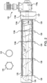
FIG. 2 provides a graphical illustration of an embodiment of the filtration assembly of the dewatering system ofFIG. 1 ; and -
FIG. 3 is a graphical illustration of an embodiment of a traditional dewatering system constructed without use of the automatically adjustable controls described in the present disclosure, showing an influent storage receptacle and filtration assembly. - Disclosed herein are detailed descriptions of specific embodiments of the dewatering systems of the present invention. It will be understood that the disclosed embodiments are merely examples of the way in which certain aspects of the invention can be implemented and do not represent an exhaustive list of all of the ways the invention may be embodied. Indeed, it will be understood that the systems, devices and methods described herein may be embodied in various and alternative forms. Moreover, the figures are not necessarily to scale and some features may be exaggerated or minimized to show details of particular components.
- Well-known components, materials or methods are not necessarily described in great detail in order to avoid obscuring the present disclosure. Any specific structural and functional details disclosed herein are not to be interpreted as limiting, but merely as a basis for the claims and as a representative basis for teaching one skilled in the art to variously employ the invention.
-
FIG. 3 is a graphical illustration of an embodiment of atraditional dewatering system 10 constructed without use of the automatically adjustable control, as described in the embodiments of the present invention.System 10 includes aninfluent storage receptacle 2 having a feed pipe 4 upstream thereof, and a filtration assembly 6 downstream ofinfluent storage receptacle 2.Dewatering system 10 includes afeed pump 3 operatively connected to feed pipe 4 to draw influent intoinfluent storage receptacle 2. Filtration assembly 6 is in fluid communication withinfluent storage receptacle 2 via a conduit 8 extending between anoutlet 11 ofinfluent storage receptacle 2 and aninlet 12 of filtration assembly 6. Amotor 22 drives filtration assembly 6. Asolids receptacle 14 is downstream of filtration assembly 6. Aneffluent collector 16 is adjacent to and downstream of filtration assembly 6 in fluid communication with filtration assembly 6. Acontrol system 20 is connected tosystem 10. Aflow rate sensor 18 is connected to feed pipe 4. - Referring now to
FIG. 1 , there is illustrated an automatically adjustable screwpress dewatering system 100 for removing solids from an influent.Dewatering system 100 includes aninfluent storage receptacle 102 having afeed pipe 104 upstream thereof, and afiltration assembly 106 downstream ofinfluent storage receptacle 102.Dewatering system 100 includes afeed pump 103 operatively connected to feedpipe 104 to draw influent intoinfluent storage receptacle 102. It is also contemplated that avalve 105, and/or aweir 107 can be operatively connected to feedpipe 104 to draw influent into theinfluent storage receptacle 102.Filtration assembly 106 is in fluid communication withinfluent storage receptacle 102 via aconduit 108 extending between anoutlet 110 ofinfluent storage receptacle 102 and aninlet 112 offiltration assembly 106. It is contemplated thatconduit 108 can be a hose, pipe, tube, pump, or other means of transporting the influent directly into the mechanical or chemical/mechanical filtration assembly 106. It is also contemplated that the influent can be stored in a location removed from theaforementioned filtration assembly 106. The influent may be gravity fed, pumped or otherwise conveyed into the mechanical or chemical/mechanical filtration assembly 106.Filtration assembly 106 acts to remove solids from the influent and generates a solid output and a filtrate oreffluent output 117. - With continued reference to
FIG. 1 , asolids receptacle 114 is downstream offiltration assembly 106. Aneffluent collector 116 is adjacent to and downstream offiltration assembly 106 in fluid communication withfiltration assembly 106.Sensors 118a-h are operatively connected to components ofdewatering system 100 to sense various characteristics of thesystem 100.Sensors 118a-c are used to determine the quantity of liquids, solids, combined liquids and solids, or liquids and solids separately, all of which are also referred to as influent, that are awaiting filtration byfiltration assembly 106. Sensors 118 may include but are not limited to contact or noncontact level sensors, pressure sensors, infrared, ultrasonic or microwave solids meters, turbidity or light sensors, or some combination thereof.Sensors 118a-h allow for continuous automatic control overdewatering system 100, which, in turn, assists in making thesystem 100 more efficient. - A
control system 120 is operatively connected tosensors 118a-h to receive at least one sensor signal therefrom and to generate an adjustment signal based on the sensor signal to improve the efficiency of the dewatering system.Control system 120 is also connected to one or more elements ofdewatering system 100 to send the adjustment signal thereto. For example,control system 120 is operatively connected to at least one offeed pump 103 and amotor 122, described below, to adjust power ofmotor 122 or the speed offeed pump 103.Control system 120 can be physically separate fromfiltration system 106 andreceptacle 102 and can be in wireless communication withsensors 118a-h and other components ofsystem 100. Moreover, in some embodiments,dewatering system 100 may accept regularly shifting flow rates from a feed pump not under control ofcontrol system 120 and compensate for them, may accept an outside requirement to increase or decrease overall system throughput and adjust system running parameters to compensate, or it may alter the feed rate to produce better performance. -
Control panel 120 will contain one Programmable Logic Controller (PLC), industrial computer, microprocessor/microcontroller device such as a Raspberry Pi or Arduino, or other computing device that will be used to execute all decision-making functions to interpret the signals fromsensors 118a-h, operate thedewatering system 100, and make all adjustments tooperating system 100 based on the signals fromsensors 118a-h. By having everything contained within asingle control panel 120 the cost of implementation can be reduced by up to an order of magnitude and reduces or eliminates entirely the typical errors caused by requiring two dissimilar computing devices to share control of one dewatering system. -
Sensor 118a is operatively connected to theconduit 108 and is a light sensor used to measure an amount of suspended solids in the influent; this includes a turbidity sensor, an interruption of light sensor, or laser beam sensor.Sensor 118b is operatively connected to feedpipe 104 and measures a density, turbidity, an amount of suspended solids, and/or a flow rate.Sensor 118c is operatively connected toinfluent storage receptacle 102.Sensor 118c is a level sensor, turbidity sensor and/or reflectivity sensor. It is also contemplated thatconduit 108,feed pipe 104 andstorage receptacle 102, can includemultiple sensors - As shown in
FIGS. 1 and2 ,sensors 118d are operatively connected tofiltration assembly 106 and measure the hydraulic and/or solids loading offiltration assembly 106. This can be done directly, e.g. with stress and/or strain sensors on the filtration assembly components, but also indirectly, e.g. by measuring characteristics of amotor 122 that drivesfiltration assembly 106, described in more detail below. In accordance with the invention,filtration assembly 106 comprises a dewatering drum 124 (e.g. cylinder) made up of anauger 126 positioned within thedrum 124, and a series of spaced apart rotating and static plates, 133 and 135, respectively. Rotating andstatic plates Sensor 118d measures pressure or strain ofdrum 124, one or more of the spaced apartplates auger 126.Filtration assembly 106 also includes apressure plate 127, and/or asupport frame 129, all of which can include one ormore sensors 118d. It is contemplated that in some embodiments, instead ofplates sensor 118d can measure pressure and/or strain of the fixed screen made of wire mesh, stamped or cut metal, and/or other similar arrangement of plastic material may be substituted. - With continued reference to
FIGS. 1 and2 , dewatering system includes amotor 122 operatively connected tofiltration assembly 106. Asensor 118g is operatively connected tomotor 122.Sensor 118g measures torque, amperage draw, rotational speed, e.g. of the motor and/or shaft, motor temperature, winding temperature, and/or power factor ofmotor 122.Sensors 118g can also measure filter mechanism rotational speed, velocity, color, ability to pass light, heat, sound or other energy through it.Control system 120 determines whetherdrum 124 can turn safely based on signals fromsensors drum 124 so that it can operate safely. If a sensor signal from any part offiltration assembly 106 ormotor 122 indicates a jam or indicates that a jam is likely to occur, the adjustment signal can include an automatic jam clearing command or can temporarily and/or permanently command adjustments to running parameters ofmotor 122 and/or other elements of the dewatering system in response to predictive indicators that a jam is likely to occur, allowing the system to continue running without interruption. - With reference now to
FIG. 1 , asensor 118e is operatively connected to solids receptacle 114 or between thesolids receptacle 114 and thefiltration assembly 106. For example, this can be accomplished bysensor 118h that includes a device for mid-air physical capture of solids falling fromfiltration assembly 106 for measurement bysensor 118h. It is also contemplated thatsensor 118h can conduct measurement and analysis as the solids are fallingpast sensor 118h fromfiltration assembly 106 tosolids receptacle 114.Sensors filtration system 106. Asensor 118f is operatively connected to theeffluent collector 116.Sensor 118f measures, directly or indirectly, an amount of suspended solids in the filtrate/effluent, or the amount of liquid or solids removed from the influent stream.Sensors 118f include, but are not limited to, contact or noncontact level sensors, pressure sensors, infrared, ultrasonic or microwave solids meters, turbidity or light sensors, color sensors, or some combination thereof, effects on a secondary filtration system, or fill rate of a container or containers for filtered solids or liquids. - With continued reference to
FIG. 1 ,dewatering system 100 will adjust running parameters viacontrol system 120 based on the various measurements received via sensor signals from one ormore sensors 118a-h and/or analysis performed on the measurements. These adjustments are made in real-time automatically to avoid potential jams, to increase processing quantity and efficiency, or the like. The real-time automatic adjustment ofcontrol system 120 means that shut down ofsystem 100 tends not to be required. Adjustments tosystem 100 are made without requiring any input or guidance from the equipment operator or any outside sensors, control panels, facility systems or aftermarket/add-on control systems beyond control signals originating fromcontrol panel 120 andsensors 118a-h that supply inputs to controlpanel 120. These running parameters include, but are not limited to, the influent feed rate tofiltration system 106, chemical dosing rate of one or more chemicals provided tosystem 100, speed of various mechanical filtration mechanisms, such as, drums, augers, plates, or other mechanisms. These parameters also include, but are not limited to, the mixing energy or velocity via impellers, blades or other mechanisms, amount of filtrate recycled, amount, temperature or pressure of wash water, or other parameters of operation ofdewatering system 100. -
Control system 120 may include continuous process improvement or learning sub-systems that record alarm conditions causing system shutdown, such as excessive power draw or overflow of influent storage receptacle. If such an alarm condition is recorded, these sub-systems may modify operating parameters to take preventative actions that grow in magnitude as the shutdown condition is approached, and if additional system shutdowns are recorded. If the preventative action is successful, these sub-systems may experimentally reduce the magnitude of preventative actions to what is required to maintain an acceptable safety margin. - In accordance with another aspect, the present invention is directed to a method for adjusting a dewatering system,
e.g. dewatering system 100, that removes liquid from an influent. The method includes determining a characteristic of an influent in at least one of an influent feed pipe, e.g.influent feed pipe 104, an influent storage receptacle, e.g.influent storage receptacle 102, or a conduit of a dewatering system,e.g. conduit 108. The method includes adjusting an operating parameter of the dewatering system based on the characteristic of the influent. - Adjusting the operating parameter of the dewatering system includes adjusting the speed of a feed pump,
e.g. feed pump 103, operatively connected to the influent feed pipe, adjusting a chemical dosing provided to thesystem 100, e.g. to feedpipe 104,receptacle 102 orsolids receptacle 114, downstream from the influent storage receptacle, and/or adjusting an influent feed rate from the influent storage receptacle to the filtration assembly. Determining characteristics of the influent, an effluent/filtrate in an effluent collector,e.g. effluent collector 116, solids in a solids receptacle, e.g. solids receptacle 114, and/or the filtration assembly includes receiving a signal from a sensor, e.g. at least one ofsensors 118a-118g, operatively connected to the dewatering system. Adjusting the operating parameter of the dewatering system includes adjusting an operating parameter based on one or more characteristics of the filtration assembly, the solids in the solids receptacle or filtrate/effluent in the effluent collector. Adjusting the operating parameter of the dewatering system can include adjusting the speed of an element,e.g. auger 126, in a filtration assembly downstream from the influent storage receptacle. -
Control system 120 may include continuous process improvement or learning sub-systems. These subsystems will modify operating parameters such as filtration assembly rotation speed, flow rate or chemical dosing rate experimentally to determine if a more efficient configuration is possible. If successful, these subsystems will adopt the new configuration. If unsuccessful, these subsystems will revert to the previous configuration and take further corrective action if required. When enabled, these subsystems may replace or augment the onsite calibration process that involves significant time and effort with an automated 'goal seeking' process that requiresdewatering system 100 to meet specified performance criteria, or that assigns weighted values to performance characteristics such as throughput, chemical dosage levels, filtrate clarity, or dewatered solids dryness. - It is believed that the present invention includes many other embodiments that may not be herein described in detail, but would nonetheless be appreciated by those skilled in the art from the disclosures made. Accordingly, the invention should not be read as being limited only to the foregoing examples or only to the designated embodiments. The invention is defined by the appended claims.
Claims (7)
- A screw press dewatering system (100) for removing solids from an influent comprising:a filtration assembly (106), which comprises a dewatering drum (124) made up of an auger (126) positioned within the drum (124) and of a series of spaced apart rotating and static plates (133, 135), which make up a filter screen;a motor (112) operatively connected to the filtration assembly (106);a feed pipe (104) upstream from the filtration assembly (106);a solids receptacle (114) downstream of the filtration assembly (106);an effluent collector (116) adjacent to the filtration assembly (106) in fluid communication with the filtration assembly (106);an influent storage receptacle (102) upstream from the filtration assembly (106) and downstream of the feed pipe (104);a conduit (108) upstream from the filtration assembly (106) and downstream from the feed pipe (104), extending between an outlet (11) of the influent storage receptacle (102) and an inlet (112) of filtration assembly (106);sensors operatively connected to components of the screw press dewatering system (100) and configured to sense various characteristics of said system, including characteristics of an influent, an effluent and a solid, so as to allow continuous automatic control of said system; anda control system (120) operatively connected to the sensors (118a - 118h) to receive a sensor signal therefrom and to generate an adjustment signal based on the sensor signal to improve the efficiency of the dewatering system,wherein said sensors comprise:a first sensor (118a) operatively connected to the conduit (108), wherein the first sensor (118a) is a light sensor used to measure at least one of an amount of suspended solids in an influent, a degree of homogeneity in an influent, a degree of flocculation of solids in an influent, or a size of flocculated solid nodules in an influent,a second sensor (118b) operatively connected to the feed pipe (104) which measures at least one of a density, an amount of suspended solids, turbidity, or a flow rate of an influent,a third sensor (118c) operatively connected to the influent storage receptacle (102), wherein the third sensor (118c) is at least one of a level sensor, turbidity sensor or reflectivity sensor, a fourth sensor (118d) operatively connected to the filtration assembly (106) which measures at least one of pressure or strain of the drum, one or more of the spaced apart plates or the auger,a fifth sensor (118e) operatively connected to the solids receptacle (114), wherein the fifth sensor (118e) measures at least one of solid content, moisture content, density, or permissivity to energy,a sixth sensor (118h) operatively connected between the filtration assembly (106) and the solids receptacle (114), wherein the sixth sensor (118h) measures at least one of solid content, moisture content, density, or permissivity to energy,a seventh sensor (118f) operatively connected to the effluent collector (116), wherein the seventh sensor (118f) measures at least one of an amount of suspended solids, turbidity, color, density, or interruption of a light or laser beam in effluent discharged from the filtration assembly (106),an eighth sensor (118g) operatively connected to the motor (112), wherein the eighth sensor (118g) measures at least one of torque, amperage draw, rotational speed, temperature or power factor of the motor (112).
- The system as recited in Claim 1, further comprising at least one of a feed pump (103), a valve (105) or a weir (107) operatively connected to the feed pipe (104) to draw influent into the influent storage receptacle (102).
- A method for adjusting a screw press dewatering system (100) according to claim 1, the method comprising:determining a characteristic of an influent, an effluent and a solid in the dewatering system; andadjusting an operating parameter of the dewatering system (100) based on the characteristic of at least one of the influent, the effluent or the solid in the dewatering system,wherein determining a characteristic of the influent includes receiving a signal from the first sensor (118a) operatively connected to the conduit (108), the second sensor (118b) operatively connected to the influent feed pipe (104), the third sensor (118c) operatively connected to the influent storage receptacle (102), and the eighth sensor (118g) operatively connected to the motor (112),further comprising determining a characteristic of the filtration assembly (106) downstream from the conduit (108) by receiving signal from the fourth sensor (118d) operatively connected to the filtration assembly (106), wherein the signal is indicative of pressure or strain, or both, wherein adjusting the operating parameter of the screw press dewatering (100) system includes adjusting the operating parameter based on the characteristic of the filtration assembly (106),wherein determining a characteristic of the solid includes determining a characteristic of the solid in the solids receptacle (114) downstream from the conduit (108) and of the solid between the filtration assembly (106) and the solids receptacle (114), wherein the fifth and the sixth sensors (118e, 118h) measure at least one of solid content, moisture content, density, or permissivity to energy, wherein adjusting the operating parameter of the screw press dewatering system (100) includes adjusting the operating parameter based on the characteristic of the solid,wherein determining a characteristic of the effluent includes receiving a signal from the seventh sensor (118f), operatively connected to the effluent collector, wherein the seventh sensor (118f) measures directly or indirectly, an amount of suspended solids in the effluent, or the amount of liquid or solids removed from the influent stream.
- The method as recited in Claim 3, wherein adjusting the operating parameter of the dewatering system (100) includes adjusting a chemical dosing provided to the dewatering system (100).
- The method as recited in Claims 3 or 4, wherein adjusting the operating parameter of the dewatering system (100) includes adjusting an influent feed rate from an influent storage receptacle (102) to a filtration assembly (106) downstream from the influent storage receptacle (102).
- The method as recited in Claims 3 to 5, wherein adjusting the operating parameter of the dewatering system (100) includes adjusting the speed of an element in a filtration assembly (106) downstream from an influent storage receptacle (102).
- The method as recited in Claims 3 to 6, wherein adjusting the operating parameter of the dewatering system includes adjusting the feed rate of an influent to the dewatering system (100) through an influent feed pipe (104) by adjusting at least one of (i) the speed of a feed pump (103) operatively connected to the influent feed pipe (104), (ii) the opening or closing of a valve (105) operatively connected to the influent feed pipe (104), or (iii) the raising or lowering of a weir (107) operatively connected to the influent feed pipe (104).
Applications Claiming Priority (2)
| Application Number | Priority Date | Filing Date | Title |
|---|---|---|---|
| US201762534582P | 2017-07-19 | 2017-07-19 | |
| PCT/US2018/042851 WO2019018616A1 (en) | 2017-07-19 | 2018-07-19 | Dewatering systems and methods |
Publications (2)
| Publication Number | Publication Date |
|---|---|
| EP3655129A1 EP3655129A1 (en) | 2020-05-27 |
| EP3655129B1 true EP3655129B1 (en) | 2025-02-12 |
Family
ID=63207871
Family Applications (1)
| Application Number | Title | Priority Date | Filing Date |
|---|---|---|---|
| EP18755350.8A Active EP3655129B1 (en) | 2017-07-19 | 2018-07-19 | Dewatering systems and methods |
Country Status (5)
| Country | Link |
|---|---|
| US (1) | US10745310B2 (en) |
| EP (1) | EP3655129B1 (en) |
| AU (2) | AU2018304302A1 (en) |
| CA (1) | CA3070426A1 (en) |
| WO (1) | WO2019018616A1 (en) |
Families Citing this family (6)
| Publication number | Priority date | Publication date | Assignee | Title |
|---|---|---|---|---|
| GB2586200A (en) * | 2019-04-25 | 2021-02-17 | Sem Energy Ltd | Apparatus and method |
| US11584660B2 (en) * | 2020-03-31 | 2023-02-21 | Hall Labs Llc | Systems and methods for dewatering, extruding, and combusting blackwater |
| AT524067B1 (en) * | 2020-07-21 | 2023-08-15 | Andritz Ag Maschf | METHOD AND DEVICE FOR MEASURING THE FILTRATE CONTENT ON A SCREW PRESS |
| BR112023024589A2 (en) * | 2021-06-01 | 2024-02-15 | Kemira Oyj | REAL-TIME DETECTION OF SOLIDS CONTENT IN AQUEOUS COLLOID DISPERSIONS SUCH AS OIL SANDS TAILINGS USING MICROWAVE SENSORS |
| CN216155724U (en) * | 2021-09-02 | 2022-04-01 | 吴云萍 | Non-abrasion lamination spiral dewatering equipment with detachable driving device |
| DE102022110244A1 (en) * | 2022-04-27 | 2023-11-02 | Johannes Biegel | Device and method for thickening a suspension which has flowable substances of different densities |
Citations (9)
| Publication number | Priority date | Publication date | Assignee | Title |
|---|---|---|---|---|
| US5037559A (en) * | 1986-12-22 | 1991-08-06 | Passavant-Werke Ag | Process for conditioning and dewatering sludges |
| US5948271A (en) * | 1995-12-01 | 1999-09-07 | Baker Hughes Incorporated | Method and apparatus for controlling and monitoring continuous feed centrifuge |
| EP1256384A2 (en) * | 1997-07-18 | 2002-11-13 | Baker Hughes Incorporated | Method and apparatus for controlling vertical and horizontal basket centrifuges |
| US6615710B1 (en) * | 1999-11-30 | 2003-09-09 | Ishigaki Company Limited | Screw press apparatus |
| JP2004090049A (en) * | 2002-08-30 | 2004-03-25 | Kubota Corp | Solid-liquid separation device |
| JP2008229678A (en) * | 2007-03-22 | 2008-10-02 | Ishigaki Co Ltd | Operation control method for multiple screw press |
| DE202012008077U1 (en) * | 2012-08-23 | 2012-09-17 | Röhren- und Pumpenwerk Bauer Gesellschaft m.b.H. | Press screw separator for separating solids from a solid-liquid mixture |
| JP2014226619A (en) * | 2013-05-23 | 2014-12-08 | 新明和工業株式会社 | Multiple plate type screw press dehydrator |
| JP2016068022A (en) * | 2014-09-30 | 2016-05-09 | 信和エンジニアリング株式会社 | Dehydrator |
Family Cites Families (19)
| Publication number | Priority date | Publication date | Assignee | Title |
|---|---|---|---|---|
| FR2322205A1 (en) * | 1975-08-26 | 1977-03-25 | Centre Rech Metallurgique | PROCESS FOR CONTROL OF THE AGGLOMERATION OF IRON ORE |
| JP3159353B2 (en) * | 1994-07-06 | 2001-04-23 | 株式会社石垣 | Control method of sludge supply pressure in screw press |
| DE19643938A1 (en) | 1996-10-31 | 1998-05-07 | Grundig Ag | Method and device for processing overspray |
| GB9701093D0 (en) | 1997-01-20 | 1997-03-12 | Tj Brent Limited | Raked bar screen |
| AUPQ758200A0 (en) | 2000-05-18 | 2000-06-08 | Cds Pty Ltd | A fine solids separator |
| DE10115179B4 (en) | 2001-03-27 | 2005-12-15 | Clausthaler Umwelttechnikinstitut Gmbh, (Cutec-Institut) | Method and measuring arrangement for automatically determining the concentration factor of conditioned sewage sludge |
| GB0122074D0 (en) | 2001-09-12 | 2001-10-31 | Copa Ltd | Filtering apparatus |
| US6849190B2 (en) * | 2001-12-19 | 2005-02-01 | Usfilter Corporation | Methods for polymer addition control for water treatment |
| US20050263448A1 (en) | 2003-05-18 | 2005-12-01 | Cds Technologies, Inc. | Systems for the removal of solids from fluids and methods of using the same |
| WO2004103916A1 (en) | 2003-05-18 | 2004-12-02 | Cds Technologies, Inc. | Systems for the removal of solids from fluids and methods of using the same |
| US20060162887A1 (en) * | 2005-01-26 | 2006-07-27 | Weinstein David I | System and method to control press section dewatering on paper and pulp drying machines using chemical dewatering agents |
| US7465391B2 (en) | 2005-09-09 | 2008-12-16 | Cds Technologies, Inc. | Apparatus for separating solids from flowing liquids |
| CA2677226C (en) * | 2007-02-02 | 2015-06-02 | Infilco Degremont Inc. | Apparatus and methods for incinerating sludge in a combustor |
| CA2629593A1 (en) * | 2008-04-11 | 2009-10-11 | James Michael Dunbar | Feedback control scheme for optimizing dewatering processes |
| FI123789B (en) | 2010-11-30 | 2013-10-31 | Metso Automation Oy | Measurement of the amount of solid in a suspension |
| JP4871437B1 (en) | 2011-01-24 | 2012-02-08 | アムコン株式会社 | Solid-liquid separator |
| CA2847959A1 (en) * | 2011-09-06 | 2013-03-14 | Anaeco Limited | Dewatering method and apparatus |
| US20130330707A1 (en) * | 2011-10-17 | 2013-12-12 | Afs Biooil Co. | Method and apparatus for dosing and supply of nutrients derived from dewatering processes |
| WO2015066275A1 (en) * | 2013-10-30 | 2015-05-07 | Flsmidth A/S | Feed conditioning automation |
-
2018
- 2018-07-19 US US16/040,001 patent/US10745310B2/en active Active
- 2018-07-19 CA CA3070426A patent/CA3070426A1/en active Pending
- 2018-07-19 EP EP18755350.8A patent/EP3655129B1/en active Active
- 2018-07-19 WO PCT/US2018/042851 patent/WO2019018616A1/en not_active Ceased
- 2018-07-19 AU AU2018304302A patent/AU2018304302A1/en not_active Abandoned
-
2023
- 2023-07-13 AU AU2023204665A patent/AU2023204665B2/en active Active
Patent Citations (9)
| Publication number | Priority date | Publication date | Assignee | Title |
|---|---|---|---|---|
| US5037559A (en) * | 1986-12-22 | 1991-08-06 | Passavant-Werke Ag | Process for conditioning and dewatering sludges |
| US5948271A (en) * | 1995-12-01 | 1999-09-07 | Baker Hughes Incorporated | Method and apparatus for controlling and monitoring continuous feed centrifuge |
| EP1256384A2 (en) * | 1997-07-18 | 2002-11-13 | Baker Hughes Incorporated | Method and apparatus for controlling vertical and horizontal basket centrifuges |
| US6615710B1 (en) * | 1999-11-30 | 2003-09-09 | Ishigaki Company Limited | Screw press apparatus |
| JP2004090049A (en) * | 2002-08-30 | 2004-03-25 | Kubota Corp | Solid-liquid separation device |
| JP2008229678A (en) * | 2007-03-22 | 2008-10-02 | Ishigaki Co Ltd | Operation control method for multiple screw press |
| DE202012008077U1 (en) * | 2012-08-23 | 2012-09-17 | Röhren- und Pumpenwerk Bauer Gesellschaft m.b.H. | Press screw separator for separating solids from a solid-liquid mixture |
| JP2014226619A (en) * | 2013-05-23 | 2014-12-08 | 新明和工業株式会社 | Multiple plate type screw press dehydrator |
| JP2016068022A (en) * | 2014-09-30 | 2016-05-09 | 信和エンジニアリング株式会社 | Dehydrator |
Also Published As
| Publication number | Publication date |
|---|---|
| WO2019018616A1 (en) | 2019-01-24 |
| EP3655129A1 (en) | 2020-05-27 |
| US10745310B2 (en) | 2020-08-18 |
| AU2018304302A1 (en) | 2020-02-13 |
| AU2023204665A1 (en) | 2023-08-03 |
| CA3070426A1 (en) | 2019-01-24 |
| AU2023204665B2 (en) | 2025-08-14 |
| US20190023598A1 (en) | 2019-01-24 |
Similar Documents
| Publication | Publication Date | Title |
|---|---|---|
| AU2023204665B2 (en) | Dewatering systems and methods | |
| AU2018102111A4 (en) | Method and arrangement for controlling a dewatering process | |
| US6143183A (en) | Method and apparatus for controlling and monitoring continuous feed centrifuge | |
| US6328897B1 (en) | Method and apparatus for controlling vertical and horizontal basket centrifuges | |
| AU2005330884B2 (en) | Sludge thickening device and sludge thickening method | |
| CA2911948C (en) | Automated dump system for solid separator | |
| JP2019051458A (en) | Dehydration system | |
| US10974176B2 (en) | Automatic control of biochemical oxygen demand content (BOD) of sludge and other products of a waste water treatment system | |
| JP4321876B1 (en) | Solid-liquid separator | |
| CN101264395B (en) | Intelligent pipeline type automatic dewaterer for oil tank and pressure tank | |
| US9725348B2 (en) | Method to provide an optimized organic load to a downstream-wastewater treatment process | |
| JP7845953B2 (en) | System for determining operating conditions of a dewatering device and method for operating a dewatering device | |
| JP3006871B2 (en) | Sludge dewatering operation control device for screw decanter centrifuge | |
| CN222922932U (en) | New sewage regulation-accident automatic control system | |
| US11389754B2 (en) | Controlling a separation device | |
| US5308504A (en) | Viscosity based tank level and flow control systems | |
| CN207119173U (en) | Subsider mud layer automatic control system | |
| JP2021159877A (en) | Screw press and how to operate the screw press | |
| CN121107645A (en) | A wastewater treatment device for lead metal smelting | |
| CN121573734A (en) | A method, system, medium, and product for treating low-turbidity water | |
| CN121494155A (en) | An integrated super magnetic separation water purification system for wastewater treatment | |
| SU929152A1 (en) | Apparatus for automatic control of pulp preparation process | |
| NL4000466A (en) | An automatic water-cutting system for industrial largescale crude oil storage tanks | |
| WO2007046050A1 (en) | Spiral separator and control system | |
| HK1147712B (en) | Method and system for particle reduction |
Legal Events
| Date | Code | Title | Description |
|---|---|---|---|
| STAA | Information on the status of an ep patent application or granted ep patent |
Free format text: STATUS: UNKNOWN |
|
| STAA | Information on the status of an ep patent application or granted ep patent |
Free format text: STATUS: THE INTERNATIONAL PUBLICATION HAS BEEN MADE |
|
| PUAI | Public reference made under article 153(3) epc to a published international application that has entered the european phase |
Free format text: ORIGINAL CODE: 0009012 |
|
| STAA | Information on the status of an ep patent application or granted ep patent |
Free format text: STATUS: REQUEST FOR EXAMINATION WAS MADE |
|
| 17P | Request for examination filed |
Effective date: 20200130 |
|
| AK | Designated contracting states |
Kind code of ref document: A1 Designated state(s): AL AT BE BG CH CY CZ DE DK EE ES FI FR GB GR HR HU IE IS IT LI LT LU LV MC MK MT NL NO PL PT RO RS SE SI SK SM TR |
|
| AX | Request for extension of the european patent |
Extension state: BA ME |
|
| DAV | Request for validation of the european patent (deleted) | ||
| DAX | Request for extension of the european patent (deleted) | ||
| STAA | Information on the status of an ep patent application or granted ep patent |
Free format text: STATUS: EXAMINATION IS IN PROGRESS |
|
| 17Q | First examination report despatched |
Effective date: 20201126 |
|
| PUAG | Search results despatched under rule 164(2) epc together with communication from examining division |
Free format text: ORIGINAL CODE: 0009017 |
|
| 17Q | First examination report despatched |
Effective date: 20210330 |
|
| B565 | Issuance of search results under rule 164(2) epc |
Effective date: 20210330 |
|
| RIC1 | Information provided on ipc code assigned before grant |
Ipc: B01D 33/00 20060101AFI20210325BHEP Ipc: B01D 37/04 20060101ALI20210325BHEP Ipc: C02F 11/125 20190101ALI20210325BHEP Ipc: C02F 11/14 20190101ALI20210325BHEP Ipc: C02F 1/52 20060101ALI20210325BHEP |
|
| GRAP | Despatch of communication of intention to grant a patent |
Free format text: ORIGINAL CODE: EPIDOSNIGR1 |
|
| STAA | Information on the status of an ep patent application or granted ep patent |
Free format text: STATUS: GRANT OF PATENT IS INTENDED |
|
| RIC1 | Information provided on ipc code assigned before grant |
Ipc: B30B 9/26 20060101ALI20240812BHEP Ipc: B30B 9/12 20060101ALI20240812BHEP Ipc: C02F 1/52 20060101ALI20240812BHEP Ipc: C02F 11/14 20190101ALI20240812BHEP Ipc: C02F 11/125 20190101ALI20240812BHEP Ipc: B01D 37/04 20060101ALI20240812BHEP Ipc: B01D 33/00 20060101AFI20240812BHEP |
|
| INTG | Intention to grant announced |
Effective date: 20240829 |
|
| GRAS | Grant fee paid |
Free format text: ORIGINAL CODE: EPIDOSNIGR3 |
|
| GRAA | (expected) grant |
Free format text: ORIGINAL CODE: 0009210 |
|
| STAA | Information on the status of an ep patent application or granted ep patent |
Free format text: STATUS: THE PATENT HAS BEEN GRANTED |
|
| AK | Designated contracting states |
Kind code of ref document: B1 Designated state(s): AL AT BE BG CH CY CZ DE DK EE ES FI FR GB GR HR HU IE IS IT LI LT LU LV MC MK MT NL NO PL PT RO RS SE SI SK SM TR |
|
| REG | Reference to a national code |
Ref country code: GB Ref legal event code: FG4D |
|
| REG | Reference to a national code |
Ref country code: CH Ref legal event code: EP |
|
| REG | Reference to a national code |
Ref country code: DE Ref legal event code: R096 Ref document number: 602018079081 Country of ref document: DE |
|
| REG | Reference to a national code |
Ref country code: IE Ref legal event code: FG4D |
|
| REG | Reference to a national code |
Ref country code: NL Ref legal event code: FP |
|
| PG25 | Lapsed in a contracting state [announced via postgrant information from national office to epo] |
Ref country code: RS Free format text: LAPSE BECAUSE OF FAILURE TO SUBMIT A TRANSLATION OF THE DESCRIPTION OR TO PAY THE FEE WITHIN THE PRESCRIBED TIME-LIMIT Effective date: 20250512 |
|
| PG25 | Lapsed in a contracting state [announced via postgrant information from national office to epo] |
Ref country code: FI Free format text: LAPSE BECAUSE OF FAILURE TO SUBMIT A TRANSLATION OF THE DESCRIPTION OR TO PAY THE FEE WITHIN THE PRESCRIBED TIME-LIMIT Effective date: 20250212 |
|
| PG25 | Lapsed in a contracting state [announced via postgrant information from national office to epo] |
Ref country code: PL Free format text: LAPSE BECAUSE OF FAILURE TO SUBMIT A TRANSLATION OF THE DESCRIPTION OR TO PAY THE FEE WITHIN THE PRESCRIBED TIME-LIMIT Effective date: 20250212 |
|
| PG25 | Lapsed in a contracting state [announced via postgrant information from national office to epo] |
Ref country code: ES Free format text: LAPSE BECAUSE OF FAILURE TO SUBMIT A TRANSLATION OF THE DESCRIPTION OR TO PAY THE FEE WITHIN THE PRESCRIBED TIME-LIMIT Effective date: 20250212 |
|
| REG | Reference to a national code |
Ref country code: LT Ref legal event code: MG9D |
|
| PG25 | Lapsed in a contracting state [announced via postgrant information from national office to epo] |
Ref country code: IS Free format text: LAPSE BECAUSE OF FAILURE TO SUBMIT A TRANSLATION OF THE DESCRIPTION OR TO PAY THE FEE WITHIN THE PRESCRIBED TIME-LIMIT Effective date: 20250612 Ref country code: NO Free format text: LAPSE BECAUSE OF FAILURE TO SUBMIT A TRANSLATION OF THE DESCRIPTION OR TO PAY THE FEE WITHIN THE PRESCRIBED TIME-LIMIT Effective date: 20250512 |
|
| PG25 | Lapsed in a contracting state [announced via postgrant information from national office to epo] |
Ref country code: HR Free format text: LAPSE BECAUSE OF FAILURE TO SUBMIT A TRANSLATION OF THE DESCRIPTION OR TO PAY THE FEE WITHIN THE PRESCRIBED TIME-LIMIT Effective date: 20250212 |
|
| PG25 | Lapsed in a contracting state [announced via postgrant information from national office to epo] |
Ref country code: PT Free format text: LAPSE BECAUSE OF FAILURE TO SUBMIT A TRANSLATION OF THE DESCRIPTION OR TO PAY THE FEE WITHIN THE PRESCRIBED TIME-LIMIT Effective date: 20250612 Ref country code: LV Free format text: LAPSE BECAUSE OF FAILURE TO SUBMIT A TRANSLATION OF THE DESCRIPTION OR TO PAY THE FEE WITHIN THE PRESCRIBED TIME-LIMIT Effective date: 20250212 |
|
| PG25 | Lapsed in a contracting state [announced via postgrant information from national office to epo] |
Ref country code: GR Free format text: LAPSE BECAUSE OF FAILURE TO SUBMIT A TRANSLATION OF THE DESCRIPTION OR TO PAY THE FEE WITHIN THE PRESCRIBED TIME-LIMIT Effective date: 20250513 Ref country code: BG Free format text: LAPSE BECAUSE OF FAILURE TO SUBMIT A TRANSLATION OF THE DESCRIPTION OR TO PAY THE FEE WITHIN THE PRESCRIBED TIME-LIMIT Effective date: 20250212 |
|
| REG | Reference to a national code |
Ref country code: AT Ref legal event code: MK05 Ref document number: 1765562 Country of ref document: AT Kind code of ref document: T Effective date: 20250212 |
|
| PGFP | Annual fee paid to national office [announced via postgrant information from national office to epo] |
Ref country code: NL Payment date: 20250726 Year of fee payment: 8 |
|
| PG25 | Lapsed in a contracting state [announced via postgrant information from national office to epo] |
Ref country code: SE Free format text: LAPSE BECAUSE OF FAILURE TO SUBMIT A TRANSLATION OF THE DESCRIPTION OR TO PAY THE FEE WITHIN THE PRESCRIBED TIME-LIMIT Effective date: 20250212 |
|
| PG25 | Lapsed in a contracting state [announced via postgrant information from national office to epo] |
Ref country code: SM Free format text: LAPSE BECAUSE OF FAILURE TO SUBMIT A TRANSLATION OF THE DESCRIPTION OR TO PAY THE FEE WITHIN THE PRESCRIBED TIME-LIMIT Effective date: 20250212 |
|
| PG25 | Lapsed in a contracting state [announced via postgrant information from national office to epo] |
Ref country code: DK Free format text: LAPSE BECAUSE OF FAILURE TO SUBMIT A TRANSLATION OF THE DESCRIPTION OR TO PAY THE FEE WITHIN THE PRESCRIBED TIME-LIMIT Effective date: 20250212 |
|
| PGFP | Annual fee paid to national office [announced via postgrant information from national office to epo] |
Ref country code: IT Payment date: 20250721 Year of fee payment: 8 |
|
| PGFP | Annual fee paid to national office [announced via postgrant information from national office to epo] |
Ref country code: GB Payment date: 20250728 Year of fee payment: 8 |
|
| PG25 | Lapsed in a contracting state [announced via postgrant information from national office to epo] |
Ref country code: AT Free format text: LAPSE BECAUSE OF FAILURE TO SUBMIT A TRANSLATION OF THE DESCRIPTION OR TO PAY THE FEE WITHIN THE PRESCRIBED TIME-LIMIT Effective date: 20250212 |
|
| PGFP | Annual fee paid to national office [announced via postgrant information from national office to epo] |
Ref country code: FR Payment date: 20250725 Year of fee payment: 8 |
|
| PG25 | Lapsed in a contracting state [announced via postgrant information from national office to epo] |
Ref country code: CZ Free format text: LAPSE BECAUSE OF FAILURE TO SUBMIT A TRANSLATION OF THE DESCRIPTION OR TO PAY THE FEE WITHIN THE PRESCRIBED TIME-LIMIT Effective date: 20250212 Ref country code: EE Free format text: LAPSE BECAUSE OF FAILURE TO SUBMIT A TRANSLATION OF THE DESCRIPTION OR TO PAY THE FEE WITHIN THE PRESCRIBED TIME-LIMIT Effective date: 20250212 |
|
| PG25 | Lapsed in a contracting state [announced via postgrant information from national office to epo] |
Ref country code: RO Free format text: LAPSE BECAUSE OF FAILURE TO SUBMIT A TRANSLATION OF THE DESCRIPTION OR TO PAY THE FEE WITHIN THE PRESCRIBED TIME-LIMIT Effective date: 20250212 |
|
| PG25 | Lapsed in a contracting state [announced via postgrant information from national office to epo] |
Ref country code: SK Free format text: LAPSE BECAUSE OF FAILURE TO SUBMIT A TRANSLATION OF THE DESCRIPTION OR TO PAY THE FEE WITHIN THE PRESCRIBED TIME-LIMIT Effective date: 20250212 |
|
| REG | Reference to a national code |
Ref country code: DE Ref legal event code: R097 Ref document number: 602018079081 Country of ref document: DE |
|
| PLBE | No opposition filed within time limit |
Free format text: ORIGINAL CODE: 0009261 |
|
| STAA | Information on the status of an ep patent application or granted ep patent |
Free format text: STATUS: NO OPPOSITION FILED WITHIN TIME LIMIT |
|
| REG | Reference to a national code |
Ref country code: CH Ref legal event code: L10 Free format text: ST27 STATUS EVENT CODE: U-0-0-L10-L00 (AS PROVIDED BY THE NATIONAL OFFICE) Effective date: 20251224 |
|
| 26N | No opposition filed |
Effective date: 20251113 |
|
| REG | Reference to a national code |
Ref country code: DE Ref legal event code: R119 Ref document number: 602018079081 Country of ref document: DE |
|
| REG | Reference to a national code |
Ref country code: CH Ref legal event code: H13 Free format text: ST27 STATUS EVENT CODE: U-0-0-H10-H13 (AS PROVIDED BY THE NATIONAL OFFICE) Effective date: 20260224 |
|
| PG25 | Lapsed in a contracting state [announced via postgrant information from national office to epo] |
Ref country code: LU Free format text: LAPSE BECAUSE OF NON-PAYMENT OF DUE FEES Effective date: 20250719 |
|
| REG | Reference to a national code |
Ref country code: BE Ref legal event code: MM Effective date: 20250731 |
|
| PG25 | Lapsed in a contracting state [announced via postgrant information from national office to epo] |
Ref country code: DE Free format text: LAPSE BECAUSE OF NON-PAYMENT OF DUE FEES Effective date: 20260203 |
|
| PG25 | Lapsed in a contracting state [announced via postgrant information from national office to epo] |
Ref country code: BE Free format text: LAPSE BECAUSE OF NON-PAYMENT OF DUE FEES Effective date: 20250731 |
|
| PG25 | Lapsed in a contracting state [announced via postgrant information from national office to epo] |
Ref country code: CH Free format text: LAPSE BECAUSE OF NON-PAYMENT OF DUE FEES Effective date: 20250731 |