EP3654875B1 - Joint arthrodesis system - Google Patents
Joint arthrodesis system Download PDFInfo
- Publication number
- EP3654875B1 EP3654875B1 EP18835779.2A EP18835779A EP3654875B1 EP 3654875 B1 EP3654875 B1 EP 3654875B1 EP 18835779 A EP18835779 A EP 18835779A EP 3654875 B1 EP3654875 B1 EP 3654875B1
- Authority
- EP
- European Patent Office
- Prior art keywords
- implant
- shaft
- framework
- joint
- blades
- Prior art date
- Legal status (The legal status is an assumption and is not a legal conclusion. Google has not performed a legal analysis and makes no representation as to the accuracy of the status listed.)
- Active
Links
Images


Classifications
-
- A—HUMAN NECESSITIES
- A61—MEDICAL OR VETERINARY SCIENCE; HYGIENE
- A61B—DIAGNOSIS; SURGERY; IDENTIFICATION
- A61B17/00—Surgical instruments, devices or methods
- A61B17/56—Surgical instruments or methods for treatment of bones or joints; Devices specially adapted therefor
- A61B17/58—Surgical instruments or methods for treatment of bones or joints; Devices specially adapted therefor for osteosynthesis, e.g. bone plates, screws or setting implements
- A61B17/68—Internal fixation devices, including fasteners and spinal fixators, even if a part thereof projects from the skin
- A61B17/70—Spinal positioners or stabilisers, e.g. stabilisers comprising fluid filler in an implant
- A61B17/7001—Screws or hooks combined with longitudinal elements which do not contact vertebrae
- A61B17/7002—Longitudinal elements, e.g. rods
- A61B17/7019—Longitudinal elements having flexible parts, or parts connected together, such that after implantation the elements can move relative to each other
- A61B17/7022—Tethers, i.e. longitudinal elements capable of transmitting tension only, e.g. straps, sutures or cables
-
- A—HUMAN NECESSITIES
- A61—MEDICAL OR VETERINARY SCIENCE; HYGIENE
- A61B—DIAGNOSIS; SURGERY; IDENTIFICATION
- A61B17/00—Surgical instruments, devices or methods
- A61B17/56—Surgical instruments or methods for treatment of bones or joints; Devices specially adapted therefor
- A61B17/58—Surgical instruments or methods for treatment of bones or joints; Devices specially adapted therefor for osteosynthesis, e.g. bone plates, screws or setting implements
- A61B17/68—Internal fixation devices, including fasteners and spinal fixators, even if a part thereof projects from the skin
- A61B17/70—Spinal positioners or stabilisers, e.g. stabilisers comprising fluid filler in an implant
- A61B17/7001—Screws or hooks combined with longitudinal elements which do not contact vertebrae
- A61B17/7032—Screws or hooks with U-shaped head or back through which longitudinal rods pass
-
- A—HUMAN NECESSITIES
- A61—MEDICAL OR VETERINARY SCIENCE; HYGIENE
- A61B—DIAGNOSIS; SURGERY; IDENTIFICATION
- A61B17/00—Surgical instruments, devices or methods
- A61B17/56—Surgical instruments or methods for treatment of bones or joints; Devices specially adapted therefor
- A61B17/58—Surgical instruments or methods for treatment of bones or joints; Devices specially adapted therefor for osteosynthesis, e.g. bone plates, screws or setting implements
- A61B17/68—Internal fixation devices, including fasteners and spinal fixators, even if a part thereof projects from the skin
- A61B17/70—Spinal positioners or stabilisers, e.g. stabilisers comprising fluid filler in an implant
- A61B17/7001—Screws or hooks combined with longitudinal elements which do not contact vertebrae
- A61B17/7044—Screws or hooks combined with longitudinal elements which do not contact vertebrae also having plates, staples or washers bearing on the vertebrae
-
- A—HUMAN NECESSITIES
- A61—MEDICAL OR VETERINARY SCIENCE; HYGIENE
- A61B—DIAGNOSIS; SURGERY; IDENTIFICATION
- A61B17/00—Surgical instruments, devices or methods
- A61B17/56—Surgical instruments or methods for treatment of bones or joints; Devices specially adapted therefor
- A61B17/58—Surgical instruments or methods for treatment of bones or joints; Devices specially adapted therefor for osteosynthesis, e.g. bone plates, screws or setting implements
- A61B17/68—Internal fixation devices, including fasteners and spinal fixators, even if a part thereof projects from the skin
- A61B17/70—Spinal positioners or stabilisers, e.g. stabilisers comprising fluid filler in an implant
- A61B17/7053—Spinal positioners or stabilisers, e.g. stabilisers comprising fluid filler in an implant with parts attached to bones or to each other by flexible wires, straps, sutures or cables
-
- A—HUMAN NECESSITIES
- A61—MEDICAL OR VETERINARY SCIENCE; HYGIENE
- A61B—DIAGNOSIS; SURGERY; IDENTIFICATION
- A61B17/00—Surgical instruments, devices or methods
- A61B17/56—Surgical instruments or methods for treatment of bones or joints; Devices specially adapted therefor
- A61B17/58—Surgical instruments or methods for treatment of bones or joints; Devices specially adapted therefor for osteosynthesis, e.g. bone plates, screws or setting implements
- A61B17/68—Internal fixation devices, including fasteners and spinal fixators, even if a part thereof projects from the skin
- A61B17/70—Spinal positioners or stabilisers, e.g. stabilisers comprising fluid filler in an implant
- A61B17/7059—Cortical plates
-
- A—HUMAN NECESSITIES
- A61—MEDICAL OR VETERINARY SCIENCE; HYGIENE
- A61B—DIAGNOSIS; SURGERY; IDENTIFICATION
- A61B17/00—Surgical instruments, devices or methods
- A61B17/56—Surgical instruments or methods for treatment of bones or joints; Devices specially adapted therefor
- A61B17/58—Surgical instruments or methods for treatment of bones or joints; Devices specially adapted therefor for osteosynthesis, e.g. bone plates, screws or setting implements
- A61B17/68—Internal fixation devices, including fasteners and spinal fixators, even if a part thereof projects from the skin
- A61B17/70—Spinal positioners or stabilisers, e.g. stabilisers comprising fluid filler in an implant
- A61B17/7062—Devices acting on, attached to, or simulating the effect of, vertebral processes, vertebral facets or ribs ; Tools for such devices
- A61B17/707—Devices acting on, or attached to, a transverse process or rib; Tools therefor
-
- A—HUMAN NECESSITIES
- A61—MEDICAL OR VETERINARY SCIENCE; HYGIENE
- A61B—DIAGNOSIS; SURGERY; IDENTIFICATION
- A61B17/00—Surgical instruments, devices or methods
- A61B17/56—Surgical instruments or methods for treatment of bones or joints; Devices specially adapted therefor
- A61B17/58—Surgical instruments or methods for treatment of bones or joints; Devices specially adapted therefor for osteosynthesis, e.g. bone plates, screws or setting implements
- A61B17/68—Internal fixation devices, including fasteners and spinal fixators, even if a part thereof projects from the skin
- A61B17/70—Spinal positioners or stabilisers, e.g. stabilisers comprising fluid filler in an implant
- A61B17/7071—Implants for expanding or repairing the vertebral arch or wedged between laminae or pedicles; Tools therefor
-
- A—HUMAN NECESSITIES
- A61—MEDICAL OR VETERINARY SCIENCE; HYGIENE
- A61B—DIAGNOSIS; SURGERY; IDENTIFICATION
- A61B17/00—Surgical instruments, devices or methods
- A61B17/56—Surgical instruments or methods for treatment of bones or joints; Devices specially adapted therefor
- A61B17/58—Surgical instruments or methods for treatment of bones or joints; Devices specially adapted therefor for osteosynthesis, e.g. bone plates, screws or setting implements
- A61B17/68—Internal fixation devices, including fasteners and spinal fixators, even if a part thereof projects from the skin
- A61B17/80—Cortical plates, i.e. bone plates; Instruments for holding or positioning cortical plates, or for compressing bones attached to cortical plates
- A61B17/809—Cortical plates, i.e. bone plates; Instruments for holding or positioning cortical plates, or for compressing bones attached to cortical plates with bone-penetrating elements, e.g. blades or prongs
-
- A—HUMAN NECESSITIES
- A61—MEDICAL OR VETERINARY SCIENCE; HYGIENE
- A61B—DIAGNOSIS; SURGERY; IDENTIFICATION
- A61B17/00—Surgical instruments, devices or methods
- A61B17/56—Surgical instruments or methods for treatment of bones or joints; Devices specially adapted therefor
- A61B17/58—Surgical instruments or methods for treatment of bones or joints; Devices specially adapted therefor for osteosynthesis, e.g. bone plates, screws or setting implements
- A61B17/68—Internal fixation devices, including fasteners and spinal fixators, even if a part thereof projects from the skin
- A61B17/84—Fasteners therefor or fasteners being internal fixation devices
- A61B17/86—Pins or screws or threaded wires; nuts therefor
- A61B17/8685—Pins or screws or threaded wires; nuts therefor comprising multiple separate parts
-
- A—HUMAN NECESSITIES
- A61—MEDICAL OR VETERINARY SCIENCE; HYGIENE
- A61F—FILTERS IMPLANTABLE INTO BLOOD VESSELS; PROSTHESES; DEVICES PROVIDING PATENCY TO, OR PREVENTING COLLAPSING OF, TUBULAR STRUCTURES OF THE BODY, e.g. STENTS; ORTHOPAEDIC, NURSING OR CONTRACEPTIVE DEVICES; FOMENTATION; TREATMENT OR PROTECTION OF EYES OR EARS; BANDAGES, DRESSINGS OR ABSORBENT PADS; FIRST-AID KITS
- A61F2/00—Filters implantable into blood vessels; Prostheses, i.e. artificial substitutes or replacements for parts of the body; Appliances for connecting them with the body; Devices providing patency to, or preventing collapsing of, tubular structures of the body, e.g. stents
- A61F2/02—Prostheses implantable into the body
- A61F2/30—Joints
- A61F2/44—Joints for the spine, e.g. vertebrae, spinal discs
- A61F2/4405—Joints for the spine, e.g. vertebrae, spinal discs for apophyseal or facet joints, i.e. between adjacent spinous or transverse processes
-
- A—HUMAN NECESSITIES
- A61—MEDICAL OR VETERINARY SCIENCE; HYGIENE
- A61F—FILTERS IMPLANTABLE INTO BLOOD VESSELS; PROSTHESES; DEVICES PROVIDING PATENCY TO, OR PREVENTING COLLAPSING OF, TUBULAR STRUCTURES OF THE BODY, e.g. STENTS; ORTHOPAEDIC, NURSING OR CONTRACEPTIVE DEVICES; FOMENTATION; TREATMENT OR PROTECTION OF EYES OR EARS; BANDAGES, DRESSINGS OR ABSORBENT PADS; FIRST-AID KITS
- A61F2/00—Filters implantable into blood vessels; Prostheses, i.e. artificial substitutes or replacements for parts of the body; Appliances for connecting them with the body; Devices providing patency to, or preventing collapsing of, tubular structures of the body, e.g. stents
- A61F2/02—Prostheses implantable into the body
- A61F2/30—Joints
- A61F2/44—Joints for the spine, e.g. vertebrae, spinal discs
- A61F2/4455—Joints for the spine, e.g. vertebrae, spinal discs for the fusion of spinal bodies, e.g. intervertebral fusion of adjacent spinal bodies, e.g. fusion cages
- A61F2/447—Joints for the spine, e.g. vertebrae, spinal discs for the fusion of spinal bodies, e.g. intervertebral fusion of adjacent spinal bodies, e.g. fusion cages substantially parallelepipedal, e.g. having a rectangular or trapezoidal cross-section
-
- A—HUMAN NECESSITIES
- A61—MEDICAL OR VETERINARY SCIENCE; HYGIENE
- A61F—FILTERS IMPLANTABLE INTO BLOOD VESSELS; PROSTHESES; DEVICES PROVIDING PATENCY TO, OR PREVENTING COLLAPSING OF, TUBULAR STRUCTURES OF THE BODY, e.g. STENTS; ORTHOPAEDIC, NURSING OR CONTRACEPTIVE DEVICES; FOMENTATION; TREATMENT OR PROTECTION OF EYES OR EARS; BANDAGES, DRESSINGS OR ABSORBENT PADS; FIRST-AID KITS
- A61F2/00—Filters implantable into blood vessels; Prostheses, i.e. artificial substitutes or replacements for parts of the body; Appliances for connecting them with the body; Devices providing patency to, or preventing collapsing of, tubular structures of the body, e.g. stents
- A61F2/02—Prostheses implantable into the body
- A61F2/30—Joints
- A61F2/46—Special tools for implanting artificial joints
- A61F2/4603—Special tools for implanting artificial joints for insertion or extraction of endoprosthetic joints or of accessories thereof
- A61F2/4611—Special tools for implanting artificial joints for insertion or extraction of endoprosthetic joints or of accessories thereof of spinal prostheses
-
- A—HUMAN NECESSITIES
- A61—MEDICAL OR VETERINARY SCIENCE; HYGIENE
- A61B—DIAGNOSIS; SURGERY; IDENTIFICATION
- A61B17/00—Surgical instruments, devices or methods
- A61B17/16—Instruments for performing osteoclasis; Drills or chisels for bones; Trepans
- A61B17/1662—Instruments for performing osteoclasis; Drills or chisels for bones; Trepans for particular parts of the body
- A61B17/1671—Instruments for performing osteoclasis; Drills or chisels for bones; Trepans for particular parts of the body for the spine
-
- A—HUMAN NECESSITIES
- A61—MEDICAL OR VETERINARY SCIENCE; HYGIENE
- A61B—DIAGNOSIS; SURGERY; IDENTIFICATION
- A61B17/00—Surgical instruments, devices or methods
- A61B2017/00831—Material properties
- A61B2017/00884—Material properties enhancing wound closure
-
- A—HUMAN NECESSITIES
- A61—MEDICAL OR VETERINARY SCIENCE; HYGIENE
- A61F—FILTERS IMPLANTABLE INTO BLOOD VESSELS; PROSTHESES; DEVICES PROVIDING PATENCY TO, OR PREVENTING COLLAPSING OF, TUBULAR STRUCTURES OF THE BODY, e.g. STENTS; ORTHOPAEDIC, NURSING OR CONTRACEPTIVE DEVICES; FOMENTATION; TREATMENT OR PROTECTION OF EYES OR EARS; BANDAGES, DRESSINGS OR ABSORBENT PADS; FIRST-AID KITS
- A61F2/00—Filters implantable into blood vessels; Prostheses, i.e. artificial substitutes or replacements for parts of the body; Appliances for connecting them with the body; Devices providing patency to, or preventing collapsing of, tubular structures of the body, e.g. stents
- A61F2/02—Prostheses implantable into the body
- A61F2/30—Joints
- A61F2/42—Joints for wrists or ankles; for hands, e.g. fingers; for feet, e.g. toes
-
- A—HUMAN NECESSITIES
- A61—MEDICAL OR VETERINARY SCIENCE; HYGIENE
- A61F—FILTERS IMPLANTABLE INTO BLOOD VESSELS; PROSTHESES; DEVICES PROVIDING PATENCY TO, OR PREVENTING COLLAPSING OF, TUBULAR STRUCTURES OF THE BODY, e.g. STENTS; ORTHOPAEDIC, NURSING OR CONTRACEPTIVE DEVICES; FOMENTATION; TREATMENT OR PROTECTION OF EYES OR EARS; BANDAGES, DRESSINGS OR ABSORBENT PADS; FIRST-AID KITS
- A61F2/00—Filters implantable into blood vessels; Prostheses, i.e. artificial substitutes or replacements for parts of the body; Appliances for connecting them with the body; Devices providing patency to, or preventing collapsing of, tubular structures of the body, e.g. stents
- A61F2/02—Prostheses implantable into the body
- A61F2/30—Joints
- A61F2/46—Special tools for implanting artificial joints
- A61F2/4603—Special tools for implanting artificial joints for insertion or extraction of endoprosthetic joints or of accessories thereof
- A61F2/4606—Special tools for implanting artificial joints for insertion or extraction of endoprosthetic joints or of accessories thereof of wrists or ankles; of hands, e.g. fingers; of feet, e.g. toes
-
- A—HUMAN NECESSITIES
- A61—MEDICAL OR VETERINARY SCIENCE; HYGIENE
- A61F—FILTERS IMPLANTABLE INTO BLOOD VESSELS; PROSTHESES; DEVICES PROVIDING PATENCY TO, OR PREVENTING COLLAPSING OF, TUBULAR STRUCTURES OF THE BODY, e.g. STENTS; ORTHOPAEDIC, NURSING OR CONTRACEPTIVE DEVICES; FOMENTATION; TREATMENT OR PROTECTION OF EYES OR EARS; BANDAGES, DRESSINGS OR ABSORBENT PADS; FIRST-AID KITS
- A61F2/00—Filters implantable into blood vessels; Prostheses, i.e. artificial substitutes or replacements for parts of the body; Appliances for connecting them with the body; Devices providing patency to, or preventing collapsing of, tubular structures of the body, e.g. stents
- A61F2/02—Prostheses implantable into the body
- A61F2/30—Joints
- A61F2002/30001—Additional features of subject-matter classified in A61F2/28, A61F2/30 and subgroups thereof
- A61F2002/30108—Shapes
- A61F2002/3011—Cross-sections or two-dimensional shapes
- A61F2002/30138—Convex polygonal shapes
- A61F2002/30158—Convex polygonal shapes trapezoidal
-
- A—HUMAN NECESSITIES
- A61—MEDICAL OR VETERINARY SCIENCE; HYGIENE
- A61F—FILTERS IMPLANTABLE INTO BLOOD VESSELS; PROSTHESES; DEVICES PROVIDING PATENCY TO, OR PREVENTING COLLAPSING OF, TUBULAR STRUCTURES OF THE BODY, e.g. STENTS; ORTHOPAEDIC, NURSING OR CONTRACEPTIVE DEVICES; FOMENTATION; TREATMENT OR PROTECTION OF EYES OR EARS; BANDAGES, DRESSINGS OR ABSORBENT PADS; FIRST-AID KITS
- A61F2/00—Filters implantable into blood vessels; Prostheses, i.e. artificial substitutes or replacements for parts of the body; Appliances for connecting them with the body; Devices providing patency to, or preventing collapsing of, tubular structures of the body, e.g. stents
- A61F2/02—Prostheses implantable into the body
- A61F2/30—Joints
- A61F2002/30001—Additional features of subject-matter classified in A61F2/28, A61F2/30 and subgroups thereof
- A61F2002/30108—Shapes
- A61F2002/3011—Cross-sections or two-dimensional shapes
- A61F2002/30159—Concave polygonal shapes
- A61F2002/30179—X-shaped
-
- A—HUMAN NECESSITIES
- A61—MEDICAL OR VETERINARY SCIENCE; HYGIENE
- A61F—FILTERS IMPLANTABLE INTO BLOOD VESSELS; PROSTHESES; DEVICES PROVIDING PATENCY TO, OR PREVENTING COLLAPSING OF, TUBULAR STRUCTURES OF THE BODY, e.g. STENTS; ORTHOPAEDIC, NURSING OR CONTRACEPTIVE DEVICES; FOMENTATION; TREATMENT OR PROTECTION OF EYES OR EARS; BANDAGES, DRESSINGS OR ABSORBENT PADS; FIRST-AID KITS
- A61F2/00—Filters implantable into blood vessels; Prostheses, i.e. artificial substitutes or replacements for parts of the body; Appliances for connecting them with the body; Devices providing patency to, or preventing collapsing of, tubular structures of the body, e.g. stents
- A61F2/02—Prostheses implantable into the body
- A61F2/30—Joints
- A61F2002/30001—Additional features of subject-matter classified in A61F2/28, A61F2/30 and subgroups thereof
- A61F2002/30108—Shapes
- A61F2002/30199—Three-dimensional shapes
- A61F2002/30261—Three-dimensional shapes parallelepipedal
- A61F2002/30266—Three-dimensional shapes parallelepipedal wedge-shaped parallelepipeds
-
- A—HUMAN NECESSITIES
- A61—MEDICAL OR VETERINARY SCIENCE; HYGIENE
- A61F—FILTERS IMPLANTABLE INTO BLOOD VESSELS; PROSTHESES; DEVICES PROVIDING PATENCY TO, OR PREVENTING COLLAPSING OF, TUBULAR STRUCTURES OF THE BODY, e.g. STENTS; ORTHOPAEDIC, NURSING OR CONTRACEPTIVE DEVICES; FOMENTATION; TREATMENT OR PROTECTION OF EYES OR EARS; BANDAGES, DRESSINGS OR ABSORBENT PADS; FIRST-AID KITS
- A61F2/00—Filters implantable into blood vessels; Prostheses, i.e. artificial substitutes or replacements for parts of the body; Appliances for connecting them with the body; Devices providing patency to, or preventing collapsing of, tubular structures of the body, e.g. stents
- A61F2/02—Prostheses implantable into the body
- A61F2/30—Joints
- A61F2002/30001—Additional features of subject-matter classified in A61F2/28, A61F2/30 and subgroups thereof
- A61F2002/30108—Shapes
- A61F2002/30199—Three-dimensional shapes
- A61F2002/3028—Three-dimensional shapes polyhedral different from parallelepipedal and pyramidal
- A61F2002/30281—Three-dimensional shapes polyhedral different from parallelepipedal and pyramidal wedge-shaped
-
- A—HUMAN NECESSITIES
- A61—MEDICAL OR VETERINARY SCIENCE; HYGIENE
- A61F—FILTERS IMPLANTABLE INTO BLOOD VESSELS; PROSTHESES; DEVICES PROVIDING PATENCY TO, OR PREVENTING COLLAPSING OF, TUBULAR STRUCTURES OF THE BODY, e.g. STENTS; ORTHOPAEDIC, NURSING OR CONTRACEPTIVE DEVICES; FOMENTATION; TREATMENT OR PROTECTION OF EYES OR EARS; BANDAGES, DRESSINGS OR ABSORBENT PADS; FIRST-AID KITS
- A61F2/00—Filters implantable into blood vessels; Prostheses, i.e. artificial substitutes or replacements for parts of the body; Appliances for connecting them with the body; Devices providing patency to, or preventing collapsing of, tubular structures of the body, e.g. stents
- A61F2/02—Prostheses implantable into the body
- A61F2/30—Joints
- A61F2002/30001—Additional features of subject-matter classified in A61F2/28, A61F2/30 and subgroups thereof
- A61F2002/30316—The prosthesis having different structural features at different locations within the same prosthesis; Connections between prosthetic parts; Special structural features of bone or joint prostheses not otherwise provided for
- A61F2002/30329—Connections or couplings between prosthetic parts, e.g. between modular parts; Connecting elements
- A61F2002/30331—Connections or couplings between prosthetic parts, e.g. between modular parts; Connecting elements made by longitudinally pushing a protrusion into a complementarily-shaped recess, e.g. held by friction fit
- A61F2002/30362—Connections or couplings between prosthetic parts, e.g. between modular parts; Connecting elements made by longitudinally pushing a protrusion into a complementarily-shaped recess, e.g. held by friction fit with possibility of relative movement between the protrusion and the recess
- A61F2002/30364—Rotation about the common longitudinal axis
- A61F2002/30365—Rotation about the common longitudinal axis with additional means for limiting said rotation
-
- A—HUMAN NECESSITIES
- A61—MEDICAL OR VETERINARY SCIENCE; HYGIENE
- A61F—FILTERS IMPLANTABLE INTO BLOOD VESSELS; PROSTHESES; DEVICES PROVIDING PATENCY TO, OR PREVENTING COLLAPSING OF, TUBULAR STRUCTURES OF THE BODY, e.g. STENTS; ORTHOPAEDIC, NURSING OR CONTRACEPTIVE DEVICES; FOMENTATION; TREATMENT OR PROTECTION OF EYES OR EARS; BANDAGES, DRESSINGS OR ABSORBENT PADS; FIRST-AID KITS
- A61F2/00—Filters implantable into blood vessels; Prostheses, i.e. artificial substitutes or replacements for parts of the body; Appliances for connecting them with the body; Devices providing patency to, or preventing collapsing of, tubular structures of the body, e.g. stents
- A61F2/02—Prostheses implantable into the body
- A61F2/30—Joints
- A61F2002/30001—Additional features of subject-matter classified in A61F2/28, A61F2/30 and subgroups thereof
- A61F2002/30316—The prosthesis having different structural features at different locations within the same prosthesis; Connections between prosthetic parts; Special structural features of bone or joint prostheses not otherwise provided for
- A61F2002/30535—Special structural features of bone or joint prostheses not otherwise provided for
- A61F2002/30537—Special structural features of bone or joint prostheses not otherwise provided for adjustable
- A61F2002/30538—Special structural features of bone or joint prostheses not otherwise provided for adjustable for adjusting angular orientation
-
- A—HUMAN NECESSITIES
- A61—MEDICAL OR VETERINARY SCIENCE; HYGIENE
- A61F—FILTERS IMPLANTABLE INTO BLOOD VESSELS; PROSTHESES; DEVICES PROVIDING PATENCY TO, OR PREVENTING COLLAPSING OF, TUBULAR STRUCTURES OF THE BODY, e.g. STENTS; ORTHOPAEDIC, NURSING OR CONTRACEPTIVE DEVICES; FOMENTATION; TREATMENT OR PROTECTION OF EYES OR EARS; BANDAGES, DRESSINGS OR ABSORBENT PADS; FIRST-AID KITS
- A61F2/00—Filters implantable into blood vessels; Prostheses, i.e. artificial substitutes or replacements for parts of the body; Appliances for connecting them with the body; Devices providing patency to, or preventing collapsing of, tubular structures of the body, e.g. stents
- A61F2/02—Prostheses implantable into the body
- A61F2/30—Joints
- A61F2002/30001—Additional features of subject-matter classified in A61F2/28, A61F2/30 and subgroups thereof
- A61F2002/30316—The prosthesis having different structural features at different locations within the same prosthesis; Connections between prosthetic parts; Special structural features of bone or joint prostheses not otherwise provided for
- A61F2002/30535—Special structural features of bone or joint prostheses not otherwise provided for
- A61F2002/30579—Special structural features of bone or joint prostheses not otherwise provided for with mechanically expandable devices, e.g. fixation devices
-
- A—HUMAN NECESSITIES
- A61—MEDICAL OR VETERINARY SCIENCE; HYGIENE
- A61F—FILTERS IMPLANTABLE INTO BLOOD VESSELS; PROSTHESES; DEVICES PROVIDING PATENCY TO, OR PREVENTING COLLAPSING OF, TUBULAR STRUCTURES OF THE BODY, e.g. STENTS; ORTHOPAEDIC, NURSING OR CONTRACEPTIVE DEVICES; FOMENTATION; TREATMENT OR PROTECTION OF EYES OR EARS; BANDAGES, DRESSINGS OR ABSORBENT PADS; FIRST-AID KITS
- A61F2/00—Filters implantable into blood vessels; Prostheses, i.e. artificial substitutes or replacements for parts of the body; Appliances for connecting them with the body; Devices providing patency to, or preventing collapsing of, tubular structures of the body, e.g. stents
- A61F2/02—Prostheses implantable into the body
- A61F2/30—Joints
- A61F2002/30001—Additional features of subject-matter classified in A61F2/28, A61F2/30 and subgroups thereof
- A61F2002/30316—The prosthesis having different structural features at different locations within the same prosthesis; Connections between prosthetic parts; Special structural features of bone or joint prostheses not otherwise provided for
- A61F2002/30535—Special structural features of bone or joint prostheses not otherwise provided for
- A61F2002/30593—Special structural features of bone or joint prostheses not otherwise provided for hollow
-
- A—HUMAN NECESSITIES
- A61—MEDICAL OR VETERINARY SCIENCE; HYGIENE
- A61F—FILTERS IMPLANTABLE INTO BLOOD VESSELS; PROSTHESES; DEVICES PROVIDING PATENCY TO, OR PREVENTING COLLAPSING OF, TUBULAR STRUCTURES OF THE BODY, e.g. STENTS; ORTHOPAEDIC, NURSING OR CONTRACEPTIVE DEVICES; FOMENTATION; TREATMENT OR PROTECTION OF EYES OR EARS; BANDAGES, DRESSINGS OR ABSORBENT PADS; FIRST-AID KITS
- A61F2/00—Filters implantable into blood vessels; Prostheses, i.e. artificial substitutes or replacements for parts of the body; Appliances for connecting them with the body; Devices providing patency to, or preventing collapsing of, tubular structures of the body, e.g. stents
- A61F2/02—Prostheses implantable into the body
- A61F2/30—Joints
- A61F2002/30001—Additional features of subject-matter classified in A61F2/28, A61F2/30 and subgroups thereof
- A61F2002/30621—Features concerning the anatomical functioning or articulation of the prosthetic joint
- A61F2002/30622—Implant for fusing a joint or bone material
-
- A—HUMAN NECESSITIES
- A61—MEDICAL OR VETERINARY SCIENCE; HYGIENE
- A61F—FILTERS IMPLANTABLE INTO BLOOD VESSELS; PROSTHESES; DEVICES PROVIDING PATENCY TO, OR PREVENTING COLLAPSING OF, TUBULAR STRUCTURES OF THE BODY, e.g. STENTS; ORTHOPAEDIC, NURSING OR CONTRACEPTIVE DEVICES; FOMENTATION; TREATMENT OR PROTECTION OF EYES OR EARS; BANDAGES, DRESSINGS OR ABSORBENT PADS; FIRST-AID KITS
- A61F2/00—Filters implantable into blood vessels; Prostheses, i.e. artificial substitutes or replacements for parts of the body; Appliances for connecting them with the body; Devices providing patency to, or preventing collapsing of, tubular structures of the body, e.g. stents
- A61F2/02—Prostheses implantable into the body
- A61F2/30—Joints
- A61F2/30721—Accessories
- A61F2/30734—Modular inserts, sleeves or augments, e.g. placed on proximal part of stem for fixation purposes or wedges for bridging a bone defect
- A61F2002/30736—Augments or augmentation pieces, e.g. wedges or blocks for bridging a bone defect
-
- A—HUMAN NECESSITIES
- A61—MEDICAL OR VETERINARY SCIENCE; HYGIENE
- A61F—FILTERS IMPLANTABLE INTO BLOOD VESSELS; PROSTHESES; DEVICES PROVIDING PATENCY TO, OR PREVENTING COLLAPSING OF, TUBULAR STRUCTURES OF THE BODY, e.g. STENTS; ORTHOPAEDIC, NURSING OR CONTRACEPTIVE DEVICES; FOMENTATION; TREATMENT OR PROTECTION OF EYES OR EARS; BANDAGES, DRESSINGS OR ABSORBENT PADS; FIRST-AID KITS
- A61F2/00—Filters implantable into blood vessels; Prostheses, i.e. artificial substitutes or replacements for parts of the body; Appliances for connecting them with the body; Devices providing patency to, or preventing collapsing of, tubular structures of the body, e.g. stents
- A61F2/02—Prostheses implantable into the body
- A61F2/30—Joints
- A61F2/30767—Special external or bone-contacting surface, e.g. coating for improving bone ingrowth
- A61F2/30771—Special external or bone-contacting surface, e.g. coating for improving bone ingrowth applied in original prostheses, e.g. holes or grooves
- A61F2002/30841—Sharp anchoring protrusions for impaction into the bone, e.g. sharp pins, spikes
- A61F2002/30845—Sharp anchoring protrusions for impaction into the bone, e.g. sharp pins, spikes with cutting edges
-
- A—HUMAN NECESSITIES
- A61—MEDICAL OR VETERINARY SCIENCE; HYGIENE
- A61F—FILTERS IMPLANTABLE INTO BLOOD VESSELS; PROSTHESES; DEVICES PROVIDING PATENCY TO, OR PREVENTING COLLAPSING OF, TUBULAR STRUCTURES OF THE BODY, e.g. STENTS; ORTHOPAEDIC, NURSING OR CONTRACEPTIVE DEVICES; FOMENTATION; TREATMENT OR PROTECTION OF EYES OR EARS; BANDAGES, DRESSINGS OR ABSORBENT PADS; FIRST-AID KITS
- A61F2/00—Filters implantable into blood vessels; Prostheses, i.e. artificial substitutes or replacements for parts of the body; Appliances for connecting them with the body; Devices providing patency to, or preventing collapsing of, tubular structures of the body, e.g. stents
- A61F2/02—Prostheses implantable into the body
- A61F2/30—Joints
- A61F2/30767—Special external or bone-contacting surface, e.g. coating for improving bone ingrowth
- A61F2/30771—Special external or bone-contacting surface, e.g. coating for improving bone ingrowth applied in original prostheses, e.g. holes or grooves
- A61F2002/30904—Special external or bone-contacting surface, e.g. coating for improving bone ingrowth applied in original prostheses, e.g. holes or grooves serrated profile, i.e. saw-toothed
-
- A—HUMAN NECESSITIES
- A61—MEDICAL OR VETERINARY SCIENCE; HYGIENE
- A61F—FILTERS IMPLANTABLE INTO BLOOD VESSELS; PROSTHESES; DEVICES PROVIDING PATENCY TO, OR PREVENTING COLLAPSING OF, TUBULAR STRUCTURES OF THE BODY, e.g. STENTS; ORTHOPAEDIC, NURSING OR CONTRACEPTIVE DEVICES; FOMENTATION; TREATMENT OR PROTECTION OF EYES OR EARS; BANDAGES, DRESSINGS OR ABSORBENT PADS; FIRST-AID KITS
- A61F2/00—Filters implantable into blood vessels; Prostheses, i.e. artificial substitutes or replacements for parts of the body; Appliances for connecting them with the body; Devices providing patency to, or preventing collapsing of, tubular structures of the body, e.g. stents
- A61F2/02—Prostheses implantable into the body
- A61F2/30—Joints
- A61F2/30988—Other joints not covered by any of the groups A61F2/32 - A61F2/4425
- A61F2002/30995—Other joints not covered by any of the groups A61F2/32 - A61F2/4425 for sacro-iliac joints
-
- A—HUMAN NECESSITIES
- A61—MEDICAL OR VETERINARY SCIENCE; HYGIENE
- A61F—FILTERS IMPLANTABLE INTO BLOOD VESSELS; PROSTHESES; DEVICES PROVIDING PATENCY TO, OR PREVENTING COLLAPSING OF, TUBULAR STRUCTURES OF THE BODY, e.g. STENTS; ORTHOPAEDIC, NURSING OR CONTRACEPTIVE DEVICES; FOMENTATION; TREATMENT OR PROTECTION OF EYES OR EARS; BANDAGES, DRESSINGS OR ABSORBENT PADS; FIRST-AID KITS
- A61F2/00—Filters implantable into blood vessels; Prostheses, i.e. artificial substitutes or replacements for parts of the body; Appliances for connecting them with the body; Devices providing patency to, or preventing collapsing of, tubular structures of the body, e.g. stents
- A61F2/02—Prostheses implantable into the body
- A61F2/30—Joints
- A61F2/44—Joints for the spine, e.g. vertebrae, spinal discs
- A61F2002/449—Joints for the spine, e.g. vertebrae, spinal discs comprising multiple spinal implants located in different intervertebral spaces or in different vertebrae
-
- A—HUMAN NECESSITIES
- A61—MEDICAL OR VETERINARY SCIENCE; HYGIENE
- A61F—FILTERS IMPLANTABLE INTO BLOOD VESSELS; PROSTHESES; DEVICES PROVIDING PATENCY TO, OR PREVENTING COLLAPSING OF, TUBULAR STRUCTURES OF THE BODY, e.g. STENTS; ORTHOPAEDIC, NURSING OR CONTRACEPTIVE DEVICES; FOMENTATION; TREATMENT OR PROTECTION OF EYES OR EARS; BANDAGES, DRESSINGS OR ABSORBENT PADS; FIRST-AID KITS
- A61F2/00—Filters implantable into blood vessels; Prostheses, i.e. artificial substitutes or replacements for parts of the body; Appliances for connecting them with the body; Devices providing patency to, or preventing collapsing of, tubular structures of the body, e.g. stents
- A61F2/02—Prostheses implantable into the body
- A61F2/30—Joints
- A61F2/46—Special tools for implanting artificial joints
- A61F2/4603—Special tools for implanting artificial joints for insertion or extraction of endoprosthetic joints or of accessories thereof
- A61F2002/4625—Special tools for implanting artificial joints for insertion or extraction of endoprosthetic joints or of accessories thereof with relative movement between parts of the instrument during use
- A61F2002/4627—Special tools for implanting artificial joints for insertion or extraction of endoprosthetic joints or of accessories thereof with relative movement between parts of the instrument during use with linear motion along or rotating motion about the instrument axis or the implantation direction, e.g. telescopic, along a guiding rod, screwing inside the instrument
-
- A—HUMAN NECESSITIES
- A61—MEDICAL OR VETERINARY SCIENCE; HYGIENE
- A61F—FILTERS IMPLANTABLE INTO BLOOD VESSELS; PROSTHESES; DEVICES PROVIDING PATENCY TO, OR PREVENTING COLLAPSING OF, TUBULAR STRUCTURES OF THE BODY, e.g. STENTS; ORTHOPAEDIC, NURSING OR CONTRACEPTIVE DEVICES; FOMENTATION; TREATMENT OR PROTECTION OF EYES OR EARS; BANDAGES, DRESSINGS OR ABSORBENT PADS; FIRST-AID KITS
- A61F2/00—Filters implantable into blood vessels; Prostheses, i.e. artificial substitutes or replacements for parts of the body; Appliances for connecting them with the body; Devices providing patency to, or preventing collapsing of, tubular structures of the body, e.g. stents
- A61F2/02—Prostheses implantable into the body
- A61F2/30—Joints
- A61F2/46—Special tools for implanting artificial joints
- A61F2002/4677—Special tools for implanting artificial joints using a guide wire
-
- A—HUMAN NECESSITIES
- A61—MEDICAL OR VETERINARY SCIENCE; HYGIENE
- A61F—FILTERS IMPLANTABLE INTO BLOOD VESSELS; PROSTHESES; DEVICES PROVIDING PATENCY TO, OR PREVENTING COLLAPSING OF, TUBULAR STRUCTURES OF THE BODY, e.g. STENTS; ORTHOPAEDIC, NURSING OR CONTRACEPTIVE DEVICES; FOMENTATION; TREATMENT OR PROTECTION OF EYES OR EARS; BANDAGES, DRESSINGS OR ABSORBENT PADS; FIRST-AID KITS
- A61F2310/00—Prostheses classified in A61F2/28 or A61F2/30 - A61F2/44 being constructed from or coated with a particular material
- A61F2310/00005—The prosthesis being constructed from a particular material
- A61F2310/00011—Metals or alloys
- A61F2310/00017—Iron- or Fe-based alloys, e.g. stainless steel
-
- A—HUMAN NECESSITIES
- A61—MEDICAL OR VETERINARY SCIENCE; HYGIENE
- A61F—FILTERS IMPLANTABLE INTO BLOOD VESSELS; PROSTHESES; DEVICES PROVIDING PATENCY TO, OR PREVENTING COLLAPSING OF, TUBULAR STRUCTURES OF THE BODY, e.g. STENTS; ORTHOPAEDIC, NURSING OR CONTRACEPTIVE DEVICES; FOMENTATION; TREATMENT OR PROTECTION OF EYES OR EARS; BANDAGES, DRESSINGS OR ABSORBENT PADS; FIRST-AID KITS
- A61F2310/00—Prostheses classified in A61F2/28 or A61F2/30 - A61F2/44 being constructed from or coated with a particular material
- A61F2310/00005—The prosthesis being constructed from a particular material
- A61F2310/00011—Metals or alloys
- A61F2310/00023—Titanium or titanium-based alloys, e.g. Ti-Ni alloys
Definitions
- the present invention is a joint arthrodesis system.
- the implant of the current system has a cutting edge as well as a rotatable cutter.
- arthrodesis procedures can be performed in the cervical spine, sacroiliac joint, ankle, hand or other similar joints.
- the DTRAX spinal system uses five instruments, a working cannula, and numerous steps.
- a working cannula with a chisel is used to breach the desired posterior facet joint. Once in position, the chisel is removed and a broach is inserted through the working cannula. The broach is advanced and retracted several times in order to remove the cartilaginous end-plates.
- a drill is inserted. After drilling is completed, a second rasp is placed to decorticate the posterior cortex. After the use of the second rasp is completed, the fixation device (filled with graft material) is inserted through the working cannula into the joint. Additional graft material is then impacted behind the implant.
- the present system's joint arthrodesis implant includes a cutting edge and one or more rotatable cutters including one or more blades.
- the cutters can assist with the postoperative stabilization of the joint implant.
- rotation of a blade about 90 degrees allows the blade to extend beyond the joint implant's framework and penetrate adjacent cartilage and bone.
- the present invention relates to a joint implant device as claimed hereafter.
- Preferred embodiments of the invention are set forth in the dependent claims
- An aspect of the present invention is to provide a joint implant with an anterior side having a cutting edge.
- Still another aspect of the present invention is to provide a joint implant with a rotatable shaft extending from the surgeon facing side having to anterior side.
- Yet still another aspect of the present invention is to provide a joint implant where rotation of the rotatable cutter causes one or more of the cutters to extend beyond the framework.
- Still another aspect of the present invention is to provide a joint implant with rotatable cutters for cutting in the clockwise or counterclockwise directions.
- Yet another aspect of the present invention is to provide a joint implant with one or more recesses capable of receiving one or more cutters, for example, when the implant is utilized in its insertion mode.
- joint implant where near the completion of the surgical procedure, the joint implant's rotating blades can be rotated to extend beyond the joint implant's framework.
- Still another aspect of the present invention is to provide edges on the cutting arms that can assist with the morselization of bone.
- a preferred embodiment of the current invention can be described as: a joint arthrodesis system comprising: a) a framework comprising: i) a longitudinal axis, openings outward from the longitudinal axis and a length greater than a width; ii) an anterior side comprising a cutting edge integral with the anterior side; iii) a surgeon facing side at an end opposite the anterior side; the anterior side having a lesser cross-sectional area than a cross-sectional area of the surgeon facing side, wherein the cross-sectional areas are determined perpendicular to the longitudinal axis; iv) a plate seated within the cross-sectional area of the surgeon facing side and affixed to the framework, wherein the plate is perpendicular to the longitudinal axis and comprises one or more apertures capable of reciprocating with one or more instruments; v) a shaft aligned with the longitudinal axis and extending between an inner side of the plate and the cutting edge; and vi) arms connected with the shaft; the arms supporting cutters comprising
- a joint implant comprising: a) a framework comprising: i) a longitudinal axis, openings outward from the longitudinal axis and a length greater than a width; ii) an anterior side comprising a cutting edge; iii) a surgeon facing side at an end opposite the anterior side, wherein the surgeon facing side is perpendicular to the longitudinal axis and comprises one or more apertures capable of reciprocating with one or more instruments; iv) a shaft aligned with the longitudinal axis and extending between an inner side of the surgeon facing side and the cutting edge; and v) one or more arms connected with the shaft; the one or more arms supporting one or more cutters comprising one or more blades, wherein on rotation of the shaft, one or more blades cut in a clockwise or counterclockwise direction.
- a joint implant comprising: a) a framework comprising: i) a longitudinal axis and openings outward from the longitudinal axis; ii) an anterior side comprising a cutting edge; iii) a surgeon facing side at an end opposite the anterior side; the surgeon facing side comprising one or more apertures; iv) a rotatable shaft extending between the cutting edge and the surgeon facing side; and v) a first arm connected with the shaft; the first arm supporting a first cutter comprising one or more blades, wherein on rotation of the shaft, the blades cut in a clockwise or counterclockwise direction.
- anterior of the joint implant means the side of the implant most distant from the surgeon and 2) "posterior or surgeon-facing side” of the joint implant means the side of the implant nearest the surgeon.
- the present invention is a joint arthrodesis system where an implant is surgically inserted into a joint space.
- the current implant can be useful for surgeries that can assist in stabilizing injured, deformed and or degenerative joints.
- Preferred embodiments of the current invention can be employed with ankle, cervical, hand, sacroiliac or other orthopaedic procedures. It appears that the present system is particularly useful for posterior cervical fusions and sacroiliac joint fusions.
- the current invention can also be used to fuse the tibia to the talus, the talus to the calcaneus, and metacarpals to the phalanges.
- Preferred embodiments of the current joint implants can be manufactured of titanium alloys, stainless steel, resorbable polymers, non-resorbable polymers or any other composition acceptable in the art. Meeting a long felt but unfilled need in the orthopaedic surgical arts, the novel and unique structures of the present combinations allow the surgical team to, among other things, simplify previous procedures.
- the present invention has a cutting edge and a rotatable cutter including one or more blades.
- the cutting edge of the implant's framework is capable of dissecting through adipose, muscle and/or joint capsule tissues.
- the rotatable cutter of the implant is capable of cutting cartilage and bone and can be associated with the creation of the surgical cavity. Further, the rotatable cutter can morselize bone in preparation for fusion.
- the combination of the cutting edge(s) and rotatable cutter of the current joint implant system meet long felt but unfilled needs in the orthopedic surgical arts: among other things, these novel and unique structures allow the surgeon to simplify the previous operating procedures utilized for posterior cervical, sacroiliac, and other joint fusions.
- the current joint arthrodesis system is also compatible with flexible drills, fiber optics, vacuums, one or more cannulas and one or more devices for inserting the joint implant. Combinations of one or more of the before identified ancillary devices and the current joint arthrodesis system can assist with the creation and healing of the surgical wound.
- Openings of the current joint implant increase the probability of the osteogenic materials and/or arthrodesis accelerating substances procuring a blood supply. And it is believed that increasing the blood supply to the osteogenic materials held by the joint implant or implant increases the probability of successful fusion. Introduction of osteogenic and other substances into the implant can hasten the healing of the surgical wound.
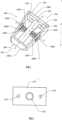
- FIG. 1 is a perspective of a preferred embodiment of the joint implant (100) utilized in the present system.
- Joint implant or implant (100) has a framework that includes an anterior side (102), surgeon facing or posterior side (104) and a plurality of lengthwise sides (108A-D) extending between anterior side (102) and surgeon facing or posterior side (104).
- Lengthwise sides (108A, 108C) are provided with opening (110) that, among other things, allows the implant's blades to rotate.
- opening (110) that, among other things, allows the implant's blades to rotate.
- the longitudinal axis of joint implant (100) is measured along axis X-X.
- Axis X-X can correspond with shaft (240) or in some preferred examples (not claimed) shaft (240) can be offset from axis X-X.
- Width of implant (100) is measured along axis Y-Y or an axis parallel to axis Y-Y shown in FIG. 1 .
- Height of joint implant is measured along axis Z-Z or an axis parallel to axis Z-Z of the joint implant's framework.
- select embodiments of implant (100) have a length greater than a width.
- the width of implant (100) is greater than the height of implant (100).
- the height of implant (100) is greater than the width of implant (100).
- Lengthwise or lateral sides (108A-108D) are positioned outward from joint implant's (100) longitudinal axis X-X.
- Select preferred embodiments of implant (100) are provided with a cross-section distant from anterior side (102) that has a greater cross-sectional area than the anterior side (102). As disclosed herein, cross-sections are determined perpendicular to the longitudinal axis X-X of the implant's framework.
- Anterior side (102) of implant (100) is provided with cutting edge (300) as will be more specifically enabled below. In some preferred embodiments, cutting edge (300) can be integral with anterior side (102) of joint implant (100).
- Attached to shaft (240) are arms (262F, 262S) supporting cutters (260F, 260S).
- cutters (260F, 260S) are supported by two arms (262F, 262S), in select preferred embodiments, cutters (260F, 260S) can be supported by a single arm (262F, 262S). Additionally, some preferred embodiments of cutters (260F, 260S) can be provided with one or more sharp edges (264F, 264S) that can assist cutters (260F, 260S) with the morselization of bone.
- Posterior side (104) of implant (100) includes cross-sectional area (120).
- Preferred embodiments of joint implant (100) are provided with plate (210) where at least a portion the plate (210) is perpendicular to longitudinal axis X-X. Plate (210) is seated within cross-sectional area (120) of surgeon facing side (104) and affixed to implant (100).
- Preferred embodiments of plate (210) are provided with one or more apertures (220) that can be utilized with one or more tools associated with the surgery.
- FIG. 2 is a frontal view of plate (210) seated in cross-sectional area (120) of surgeon facing side (104) of implant (100). As shown, cross-sectional area is provided with a plurality of openings (220).
- FIG. 3 is a top view of implant (100), where implant is shown in its subcutaneous surgical wound creation mode.
- Shaft (240) is connected with anterior end (102) and surgeon posterior side (104) in any manner acceptable in the art.
- Proximate shaft (240) is opening (110) and lateral sides (108A-108D).
- First arms (262F) attach first cutter (260F) to shaft (240).
- Second arms (262S) attach second cutter (260S) to shaft (240).
- Cutters (260F and 260S) can be provided with blades that cut in both the clockwise and counterclockwise directions when shaft (240) is rotated.
- Lateral side (108B) is provided with recess (266F) capable of receiving cutter (260F).
- Lateral side (108D) is provided with recess (266S) capable of receiving cutter (260S). As shown in FIG. 3 , recess (266F) is located on the superior side of lengthwise side (108B) and recess (266S) is positioned on the inferior side of lengthwise side (108D).
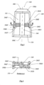
- FIG. 4 is a frontal view cross-section of implant (100) along section A-A as seen from the posterior side (104).
- Cutter (260F) is received in recess (266F) of lateral side (108B) and arms (262F) attach cutter (260F) to shaft (240).
- Cutter (260S) is received in recess (266S) of lateral side (108D) and arms (262S) attach cutter (260S) to shaft (240).
- cutters (260F, 260S) can be supported by a single arm (262F, 262S). And when surgical parameters require, implant (100) is engineered with only a single cutter (260F).
- FIG. 5 is a perspective of a preferred embodiment of implant (100).
- Shaft (240) extends from cutting edge (300) toward surgeon facing side (104) of implant (100).
- shaft (240) has rotatable arms (262F, 262S) carrying cutters (260F, 260S) such that rotation of shaft (240) extends cutter (260F) beyond lateral side (108C) and cutter (260S) beyond lateral side (108A) of implant (100).
- FIG. 6 is a frontal view of a preferred embodiment of cutter (260F) shown in FIG. 5 as seen from the anterior side of implant (100).
- Cutter (260F) is provided with first and second cutting blades (268F, 268S) that allow cutter (260F) to cut in both the clockwise and counterclockwise directions.
- cutters (260F, 260S) can be equipped with one or more cutting blades.
- cutting blades (268F, 268S) can be rotated to cut into bone so that cutters (260F, 260S) further anchor the implant (100) within the joint space.
- FIG. 7 is a perspective of cutting edge (300) of implant (100).
- Cutting edge (300) can be integral with implant (100) or cutting edge (300) can be manufactured as an interchangeable fitting for implant (100).
- cutting edges (300) are capable of dissecting through adipose, muscle and/or joint capsule tissues.
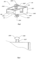
- FIG. 8 is a lateral view as seen from side (108B) with lateral sides (108A-D) of implant (100) cut away.
- Plate (210) includes aperture (220) capable of receiving hand tool (360).
- Hand tool (360) includes handle (362) and stem (364) that extends from handle (362).
- Shaft (240) includes receptacle (244) for reciprocating with stem (364) of hand tool (360). Interaction between stem (364) and receptacle (244) allows hand tool (360) to rotate cutters (260F, 260S) in both clockwise and counterclockwise directions.
- receptacle (244) can extend the entire length of (240) for allowing ingress and egress of surgical appliances and instruments from the surgical field, e.g., wires, cannulas, vacuum tubes, fiber optics, etc.
- FIG. 9 is a perspective of a preferred embodiment of implant (100) that depicts cutting edge (300), rotatable cutters (260F, 260S) and opening (110) of implant (100). As shown, barbs (280) extend away from surfaces of lengthwise sides (108B, 108C, 108D). It is believed that barbs (280) can assist in deterring movement of implant (100) within the joint space.
- FIG. 10 is a perspective of a preferred embodiment of implant (100) that depicts cutting edge (300), rotatable cutters (260F, 260S) and opening (110) of implant (100).
- surfaces of lengthwise sides (108B, 108C, 108D) are provided with micropores (290) of various volumes. It is believed that surface micropores (290) can assist with long term fixation of the implant by allowing more bone ingrowth into the implant.
- micropores (290) are generated by surface treatments to at least a portion of surfaces of lengthwise sides (108B, 108C, 108D). Micropores (290) can be created by abrasive, chemical or laser means.
- FIG. 11 is a perspective of a preferred embodiment of implant (100) where cutters (260F, 260S) are capable of being rotated 360 degrees about longitudinal axis X-X.
- FIG. 12 is another perspective of a preferred embodiment of implant (100) where cutters (260F, 260S) are capable of being rotated 360 degrees about longitudinal axis X-X.
- cutting edge (300) As measured along longitudinal axis X-X of implant's (100) framework, preferred embodiments are provided with cutting edge (300) that can be up to about 3 millimeters in length.
- the length of implant (100), including cutting edge (300) can be from about 50 millimeters to about 6 millimeters.
- Cross-sectional widths of cutting edge (300) can range from about 2 millimeters 2 to about 18 millimeters 2 .
- Cross-sectional widths of implant (100), other than cutting edge (300) can range from about 8 millimeters 2 to about 45 millimeters 2 .
Landscapes
- Health & Medical Sciences (AREA)
- Orthopedic Medicine & Surgery (AREA)
- Engineering & Computer Science (AREA)
- Biomedical Technology (AREA)
- Neurology (AREA)
- Life Sciences & Earth Sciences (AREA)
- Surgery (AREA)
- Public Health (AREA)
- Heart & Thoracic Surgery (AREA)
- Veterinary Medicine (AREA)
- Animal Behavior & Ethology (AREA)
- General Health & Medical Sciences (AREA)
- Transplantation (AREA)
- Nuclear Medicine, Radiotherapy & Molecular Imaging (AREA)
- Medical Informatics (AREA)
- Molecular Biology (AREA)
- Vascular Medicine (AREA)
- Oral & Maxillofacial Surgery (AREA)
- Cardiology (AREA)
- Physical Education & Sports Medicine (AREA)
- Prostheses (AREA)
- Surgical Instruments (AREA)
Description
- Priority to
US Provisional Patent Application, Serial No. 62/534,155 entitled - Joint Arthrodesis System - filed on July 18, 2017 - The present invention is a joint arthrodesis system. Among other things, the implant of the current system has a cutting edge as well as a rotatable cutter.
- Any discussion of references cited in this Description of the Previous Art merely summarizes the disclosures of the cited references and Applicant makes no admission that any cited reference or portion thereof is relevant prior art. Applicant reserves the right to challenge the accuracy, relevancy and veracity of the cited references.
- 1)
US Patent No. 6770096-Bolger, et al. discloses an interbody spinal stabilization cage and spinal stabilization method. Among other things, Bolger does not disclose a framework comprising: an anterior side comprising a cutting edge; a rotatable shaft extending between the cutting edge and the surgeon facing side; and a first arm connected with the shaft; the first arm supporting a first cutter comprising one or more blades, wherein on rotation of the shaft, the blades cut in a clockwise or counterclockwise direction. - 2)
US Patent No. 6824564 -Crozet discloses a two-part intersomatic implant. Among other things, Crozet does not disclose a framework comprising: an anterior side comprising a cutting edge; a rotatable shaft extending between the cutting edge and the surgeon facing side; and a first arm connected with the shaft; the first arm supporting a first cutter comprising one or more blades, wherein on rotation of the shaft, the blades cut in a clockwise or counterclockwise direction. - 3)
US Patent No. 6981975 -Michelson discloses a method for inserting a spinal fusion implant having deployable bone engaging projections. Among other things, Michelson does not disclose a framework comprising: an anterior side comprising a cutting edge; a rotatable shaft extending between the cutting edge and the surgeon facing side; and a first arm connected with the shaft; the first arm supporting a first cutter comprising one or more blades, wherein on rotation of the shaft, the blades cut in a clockwise or counterclockwise direction. - 4)
US Patent No. 7594932-Aferzon, et al . enables an apparatus for anterior intervertebral spinal fixation and fusion. Among other things, Aferzon does not disclose a framework comprising: an anterior side comprising a cutting edge; a rotatable shaft extending between the cutting edge and the surgeon facing side; and a first arm connected with the shaft; the first arm supporting a first cutter comprising one or more blades, wherein on rotation of the shaft, the blades cut in a clockwise or counterclockwise direction. - 5)
US Patent No. 8366774-Bruffey, et al. discloses an apparatus for anterior intervertebral spinal fixation and fusion. Among other things, Bruffey does not disclose a framework comprising: an anterior side comprising a cutting edge; a rotatable shaft extending between the cutting edge and the surgeon facing side; and a first arm connected with the shaft; the first arm supporting a first cutter comprising one or more blades, wherein on rotation of the shaft, the blades cut in a clockwise or counterclockwise direction. - 6)
US Patent No. 8382843-Laurence, et al. discloses an intervertebral implant with blades for connecting to adjacent vertebral bodies. Among other things, Laurence does not disclose a framework comprising: an anterior side comprising a cutting edge; a rotatable shaft extending between the cutting edge and the surgeon facing side; and a first arm connected with the shaft; the first arm supporting a first cutter comprising one or more blades, wherein on rotation of the shaft, the blades cut in a clockwise or counterclockwise direction. - 7)
US Patent No. 9539110-Bergey - 8)
US Published Patent Application No. 20070270961 -Ferguson discloses a spinal implant deployable with retractable barbs. Among other things, Ferguson does not disclose a framework comprising: an anterior side comprising a cutting edge; a rotatable shaft extending between the cutting edge and the surgeon facing side; and a first arm connected with the shaft; the first arm supporting a first cutter comprising one or more blades, wherein on rotation of the shaft, the blades cut in a clockwise or counterclockwise direction. - 9)
US Published Patent Application No. 20080027550-Link, et al. discloses a cervical intervertebral disc prosthesis comprising an anti-dislocation device and instruments. Among other things, Link does not disclose a framework comprising: an anterior side comprising a cutting edge; a rotatable shaft extending between the cutting edge and the surgeon facing side; and a first arm connected with the shaft; the first arm supporting a first cutter comprising one or more blades, wherein on rotation of the shaft, the blades cut in a clockwise or counterclockwise direction. - 10)
US Published Patent Application No. 20140121773-Patel, et al. discloses a stand-alone interbody fixation system. Among other things, Patel does not disclose a framework comprising: an anterior side comprising a cutting edge; a rotatable shaft extending between the cutting edge and the surgeon facing side; and a first arm connected with the shaft; the first arm supporting a first cutter comprising one or more blades, wherein on rotation of the shaft, the blades cut in a clockwise or counterclockwise direction. - 11)
US Published Patent Application No. 20160374831-Duffield, et al. discloses an interbody fusion device and system for implantation. Among other things, Duffield does not disclose a framework comprising: an anterior side comprising a cutting edge; a rotatable shaft extending between the cutting edge and the surgeon facing side; and a first arm connected with the shaft; the first arm supporting a first cutter comprising one or more blades, wherein on rotation of the shaft, the blades cut in a clockwise or counterclockwise direction. - 12) WIPO Published Patent Application No.
2007/079021-Aferzon, et al. discloses an apparatus for anterior intervertebral spinal fixation and fusion. The Specification of WIPO Published Patent Application No.2007/079021-Aferzon, et al. is similar toUS Patent No. 7594932-Aferzon, et al. Therefore, among other things, Aferzon does not disclose a framework comprising: an anterior side comprising a cutting edge; a rotatable shaft extending between the cutting edge and the surgeon facing side; and a first arm connected with the shaft; the first arm supporting a first cutter comprising one or more blades, wherein on rotation of the shaft, the blades cut in a clockwise or counterclockwise direction. - 13)
US Published PAtent Applications No. 2014/094918 and2015/265416 disclose further joint implants in the form of intervbody fusion devices, forming a framework and comprising a rotatable shaft, coaxial with said central axis, extending between the cage anterior side and posterior, surgeon facing side; these implants further disclose arms connected with said shaft, each supporting a cutter comprising one or more blades, wherein on rotation of said shaft, said blades rotate in a clockwise or counterclockwise direction and anchor the cage in the neighbouring vertebrae. - The more tools or instruments inserted into a surgical field, the greater the possibility of an error or patient injury may occur. Due to the simplicity of the current joint arthrodesis system, a number of surgical tools required and steps associated with performing prior state-of-the-art fusions can be eliminated. The arthrodesis procedures, among other uses, can be performed in the cervical spine, sacroiliac joint, ankle, hand or other similar joints.
- One of the currently available state-of-the art techniques for cervical fusions is the DTRAX system. The DTRAX spinal system uses five instruments, a working cannula, and numerous steps. A working cannula with a chisel is used to breach the desired posterior facet joint. Once in position, the chisel is removed and a broach is inserted through the working cannula. The broach is advanced and retracted several times in order to remove the cartilaginous end-plates. After the broach is removed from the working cannula, a drill is inserted. After drilling is completed, a second rasp is placed to decorticate the posterior cortex. After the use of the second rasp is completed, the fixation device (filled with graft material) is inserted through the working cannula into the joint. Additional graft material is then impacted behind the implant.
- Current state-of-the-art sacroiliac surgical procedures require a fusion device that is either inserted from a posterior or lateral approach. Applicant's understanding is: there are fusion devices for use with either the posterior approach or the lateral approach, but the same fusion device is incapable for use with both the posterior and the lateral approaches. Many of the current sacroiliac fusion procedures require the use of working cannulas, numerous broaches, rasps, drills and other devices that tend to complicate the surgical procedure. Applicant's current joint arthrodesis system can accomplish sacroiliac fusions through either a posterior or lateral approach with fewer surgical tools and steps.
- Unlike other joint arthrodesis systems, the present system's joint arthrodesis implant includes a cutting edge and one or more rotatable cutters including one or more blades. Among other things, it is believed that the cutters can assist with the postoperative stabilization of the joint implant. In accordance with the current invention, rotation of a blade about 90 degrees allows the blade to extend beyond the joint implant's framework and penetrate adjacent cartilage and bone.
- The present invention relates to a joint implant device as claimed hereafter. Preferred embodiments of the invention are set forth in the dependent claims
- An aspect of the present invention is to provide a joint implant with an anterior side having a cutting edge.
- Still another aspect of the present invention is to provide a joint implant with a rotatable shaft extending from the surgeon facing side having to anterior side.
- It is still another aspect of the present invention to provide a joint implant with one or more rotatable cutters affixed to the shaft, where each cutter includes one or more blades.
- Yet still another aspect of the present invention is to provide a joint implant where rotation of the rotatable cutter causes one or more of the cutters to extend beyond the framework.
- Still another aspect of the present invention is to provide a joint implant with rotatable cutters for cutting in the clockwise or counterclockwise directions.
- Yet another aspect of the present invention is to provide a joint implant with one or more recesses capable of receiving one or more cutters, for example, when the implant is utilized in its insertion mode.
- It is still another aspect of the present invention to provide a joint implant where near the completion of the surgical procedure, the joint implant's rotating blades can be rotated to extend beyond the joint implant's framework.
- Still another aspect of the present invention is to provide edges on the cutting arms that can assist with the morselization of bone.
- A preferred embodiment of the current invention can be described as: a joint arthrodesis system comprising: a) a framework comprising: i) a longitudinal axis, openings outward from the longitudinal axis and a length greater than a width; ii) an anterior side comprising a cutting edge integral with the anterior side; iii) a surgeon facing side at an end opposite the anterior side; the anterior side having a lesser cross-sectional area than a cross-sectional area of the surgeon facing side, wherein the cross-sectional areas are determined perpendicular to the longitudinal axis; iv) a plate seated within the cross-sectional area of the surgeon facing side and affixed to the framework, wherein the plate is perpendicular to the longitudinal axis and comprises one or more apertures capable of reciprocating with one or more instruments; v) a shaft aligned with the longitudinal axis and extending between an inner side of the plate and the cutting edge; and vi) arms connected with the shaft; the arms supporting cutters comprising one or more blades, wherein on rotation of the shaft, the one or more blades cut in a clockwise or counterclockwise direction; and b) a tool capable of rotating the shaft.
- Another preferred embodiment of the current invention can be described as: a joint implant comprising: a) a framework comprising: i) a longitudinal axis, openings outward from the longitudinal axis and a length greater than a width; ii) an anterior side comprising a cutting edge; iii) a surgeon facing side at an end opposite the anterior side, wherein the surgeon facing side is perpendicular to the longitudinal axis and comprises one or more apertures capable of reciprocating with one or more instruments; iv) a shaft aligned with the longitudinal axis and extending between an inner side of the surgeon facing side and the cutting edge; and v) one or more arms connected with the shaft; the one or more arms supporting one or more cutters comprising one or more blades, wherein on rotation of the shaft, one or more blades cut in a clockwise or counterclockwise direction.
- Still another preferred embodiment of the current invention can be described as: a joint implant comprising: a) a framework comprising: i) a longitudinal axis and openings outward from the longitudinal axis; ii) an anterior side comprising a cutting edge; iii) a surgeon facing side at an end opposite the anterior side; the surgeon facing side comprising one or more apertures; iv) a rotatable shaft extending between the cutting edge and the surgeon facing side; and v) a first arm connected with the shaft; the first arm supporting a first cutter comprising one or more blades, wherein on rotation of the shaft, the blades cut in a clockwise or counterclockwise direction.
- It is the novel and unique interaction of these simple elements which creates the system within the ambit of the present invention. However, it is to be understood that the descriptions of the preferred embodiments do not limit the scope of the present invention.
-
-
FIG. 1 is a perspective of a preferred embodiment of the joint implant (100) utilized in the present system. -
FIG. 2 is a frontal view of plate (210) seated in cross-sectional area (120) of surgeon facing side (104) of implant (100). -
FIG. 3 is a top view of implant (100). -
FIG. 4 is a frontal view cross-section of implant (100) along section A-A as seen from the posterior side (104). -
FIG. 5 is a perspective of implant (100). -
FIG. 6 is a frontal view of a preferred embodiment of cutter (260F) shown inFIG. 5 as seen from the anterior side of implant (100). -
FIG. 7 is a perspective of cutting edge (300) of implant (100). -
FIG. 8 is a lateral view as seen from side (108B) with lateral sides (108A-D) of implant (100) cut away. -
FIG. 9 is a perspective of a preferred embodiment of implant (100). -
FIG. 10 is a perspective of a preferred embodiment of implant (100). -
FIG. 11 is a perspective of a preferred embodiment of implant (100) where cutters (260F, 260S) are capable of being rotated 360 degrees about longitudinal axis X-X. -
FIG. 12 is another perspective of a preferred embodiment of implant (100) where cutters (260F, 260S) are capable of being rotated 360 degrees about longitudinal axis X-X. - Although the disclosure hereof is detailed to enable those skilled in the art to practice the invention, the embodiments published herein merely exemplify the present invention.
- As used herein, with respect to the joint arthrodesis system's implant: 1) "anterior" of the joint implant means the side of the implant most distant from the surgeon and 2) "posterior or surgeon-facing side" of the joint implant means the side of the implant nearest the surgeon.
- In the most general sense, the present invention is a joint arthrodesis system where an implant is surgically inserted into a joint space. The current implant can be useful for surgeries that can assist in stabilizing injured, deformed and or degenerative joints. Preferred embodiments of the current invention can be employed with ankle, cervical, hand, sacroiliac or other orthopaedic procedures. It appears that the present system is particularly useful for posterior cervical fusions and sacroiliac joint fusions. However, the current invention can also be used to fuse the tibia to the talus, the talus to the calcaneus, and metacarpals to the phalanges.
- Preferred embodiments of the current joint implants can be manufactured of titanium alloys, stainless steel, resorbable polymers, non-resorbable polymers or any other composition acceptable in the art. Meeting a long felt but unfilled need in the orthopaedic surgical arts, the novel and unique structures of the present combinations allow the surgical team to, among other things, simplify previous procedures.
- The present invention has a cutting edge and a rotatable cutter including one or more blades. The cutting edge of the implant's framework is capable of dissecting through adipose, muscle and/or joint capsule tissues. The rotatable cutter of the implant is capable of cutting cartilage and bone and can be associated with the creation of the surgical cavity. Further, the rotatable cutter can morselize bone in preparation for fusion. The combination of the cutting edge(s) and rotatable cutter of the current joint implant system meet long felt but unfilled needs in the orthopedic surgical arts: among other things, these novel and unique structures allow the surgeon to simplify the previous operating procedures utilized for posterior cervical, sacroiliac, and other joint fusions.
- Devices that insert osteogenic and/or other substances into the interior volume of the implant can be used with the present invention. The current joint arthrodesis system is also compatible with flexible drills, fiber optics, vacuums, one or more cannulas and one or more devices for inserting the joint implant. Combinations of one or more of the before identified ancillary devices and the current joint arthrodesis system can assist with the creation and healing of the surgical wound.
- Openings of the current joint implant increase the probability of the osteogenic materials and/or arthrodesis accelerating substances procuring a blood supply. And it is believed that increasing the blood supply to the osteogenic materials held by the joint implant or implant increases the probability of successful fusion. Introduction of osteogenic and other substances into the implant can hasten the healing of the surgical wound.
-
FIG. 1 is a perspective of a preferred embodiment of the joint implant (100) utilized in the present system. Joint implant or implant (100) has a framework that includes an anterior side (102), surgeon facing or posterior side (104) and a plurality of lengthwise sides (108A-D) extending between anterior side (102) and surgeon facing or posterior side (104). Lengthwise sides (108A, 108C) are provided with opening (110) that, among other things, allows the implant's blades to rotate. When surgical parameters require, osteogenic and/or other substances can also be placed into the internal volume of implant (100). - With respect to this application, the longitudinal axis of joint implant (100) is measured along axis X-X. Axis X-X can correspond with shaft (240) or in some preferred examples (not claimed) shaft (240) can be offset from axis X-X. Width of implant (100) is measured along axis Y-Y or an axis parallel to axis Y-Y shown in
FIG. 1 . Height of joint implant is measured along axis Z-Z or an axis parallel to axis Z-Z of the joint implant's framework. - Within the scope of the current invention, select embodiments of implant (100) have a length greater than a width. In select preferred embodiments, the width of implant (100) is greater than the height of implant (100). In other preferred embodiments of implant (100), the height of implant (100) is greater than the width of implant (100). The inward sides of anterior side (102), posterior side (104) and lengthwise sides (108A-D) facing longitudinal axis X-X create an available inner volume of implant (100) which can receive osteogenic as well as other substances.
- Lengthwise or lateral sides (108A-108D) are positioned outward from joint implant's (100) longitudinal axis X-X. Select preferred embodiments of implant (100) are provided with a cross-section distant from anterior side (102) that has a greater cross-sectional area than the anterior side (102). As disclosed herein, cross-sections are determined perpendicular to the longitudinal axis X-X of the implant's framework. Anterior side (102) of implant (100) is provided with cutting edge (300) as will be more specifically enabled below. In some preferred embodiments, cutting edge (300) can be integral with anterior side (102) of joint implant (100). Attached to shaft (240) are arms (262F, 262S) supporting cutters (260F, 260S). Although as shown in
FIG. 1 , cutters (260F, 260S) are supported by two arms (262F, 262S), in select preferred embodiments, cutters (260F, 260S) can be supported by a single arm (262F, 262S). Additionally, some preferred embodiments of cutters (260F, 260S) can be provided with one or more sharp edges (264F, 264S) that can assist cutters (260F, 260S) with the morselization of bone. - Posterior side (104) of implant (100) includes cross-sectional area (120). Preferred embodiments of joint implant (100) are provided with plate (210) where at least a portion the plate (210) is perpendicular to longitudinal axis X-X. Plate (210) is seated within cross-sectional area (120) of surgeon facing side (104) and affixed to implant (100). Preferred embodiments of plate (210) are provided with one or more apertures (220) that can be utilized with one or more tools associated with the surgery.
-
FIG. 2 is a frontal view of plate (210) seated in cross-sectional area (120) of surgeon facing side (104) of implant (100). As shown, cross-sectional area is provided with a plurality of openings (220). -
FIG. 3 is a top view of implant (100), where implant is shown in its subcutaneous surgical wound creation mode. Shaft (240) is connected with anterior end (102) and surgeon posterior side (104) in any manner acceptable in the art. Proximate shaft (240) is opening (110) and lateral sides (108A-108D). First arms (262F) attach first cutter (260F) to shaft (240). Second arms (262S) attach second cutter (260S) to shaft (240). Cutters (260F and 260S) can be provided with blades that cut in both the clockwise and counterclockwise directions when shaft (240) is rotated. Lateral side (108B) is provided with recess (266F) capable of receiving cutter (260F). Lateral side (108D) is provided with recess (266S) capable of receiving cutter (260S). As shown inFIG. 3 , recess (266F) is located on the superior side of lengthwise side (108B) and recess (266S) is positioned on the inferior side of lengthwise side (108D). -
FIG. 4 is a frontal view cross-section of implant (100) along section A-A as seen from the posterior side (104). Cutter (260F) is received in recess (266F) of lateral side (108B) and arms (262F) attach cutter (260F) to shaft (240). Cutter (260S) is received in recess (266S) of lateral side (108D) and arms (262S) attach cutter (260S) to shaft (240). Within the scope of the current invention, cutters (260F, 260S) can be supported by a single arm (262F, 262S). And when surgical parameters require, implant (100) is engineered with only a single cutter (260F). -
FIG. 5 is a perspective of a preferred embodiment of implant (100). Shaft (240) extends from cutting edge (300) toward surgeon facing side (104) of implant (100). As shown inFIG. 5 , shaft (240) has rotatable arms (262F, 262S) carrying cutters (260F, 260S) such that rotation of shaft (240) extends cutter (260F) beyond lateral side (108C) and cutter (260S) beyond lateral side (108A) of implant (100). -
FIG. 6 is a frontal view of a preferred embodiment of cutter (260F) shown inFIG. 5 as seen from the anterior side of implant (100). Cutter (260F) is provided with first and second cutting blades (268F, 268S) that allow cutter (260F) to cut in both the clockwise and counterclockwise directions. Depending on engineering parameters cutters (260F, 260S) can be equipped with one or more cutting blades. Along with the cutting function of cutters (260F, 260S), near the conclusion of the surgical procedure, cutting blades (268F, 268S) can be rotated to cut into bone so that cutters (260F, 260S) further anchor the implant (100) within the joint space. -
FIG. 7 is a perspective of cutting edge (300) of implant (100). Cutting edge (300) can be integral with implant (100) or cutting edge (300) can be manufactured as an interchangeable fitting for implant (100). Within the ambit of the current joint arthrodesis system, cutting edges (300) are capable of dissecting through adipose, muscle and/or joint capsule tissues. -
FIG. 8 is a lateral view as seen from side (108B) with lateral sides (108A-D) of implant (100) cut away. Plate (210) includes aperture (220) capable of receiving hand tool (360). Hand tool (360) includes handle (362) and stem (364) that extends from handle (362). Shaft (240) includes receptacle (244) for reciprocating with stem (364) of hand tool (360). Interaction between stem (364) and receptacle (244) allows hand tool (360) to rotate cutters (260F, 260S) in both clockwise and counterclockwise directions. In select preferred embodiments receptacle (244) can extend the entire length of (240) for allowing ingress and egress of surgical appliances and instruments from the surgical field, e.g., wires, cannulas, vacuum tubes, fiber optics, etc. -
FIG. 9 is a perspective of a preferred embodiment of implant (100) that depicts cutting edge (300), rotatable cutters (260F, 260S) and opening (110) of implant (100). As shown, barbs (280) extend away from surfaces of lengthwise sides (108B, 108C, 108D). It is believed that barbs (280) can assist in deterring movement of implant (100) within the joint space. -
FIG. 10 is a perspective of a preferred embodiment of implant (100) that depicts cutting edge (300), rotatable cutters (260F, 260S) and opening (110) of implant (100). In theFIG. 10 embodiment, surfaces of lengthwise sides (108B, 108C, 108D) are provided with micropores (290) of various volumes. It is believed that surface micropores (290) can assist with long term fixation of the implant by allowing more bone ingrowth into the implant. In accordance with theFIG. 10 preferred embodiment of spinal implant (100), micropores (290) are generated by surface treatments to at least a portion of surfaces of lengthwise sides (108B, 108C, 108D). Micropores (290) can be created by abrasive, chemical or laser means. -
FIG. 11 is a perspective of a preferred embodiment of implant (100) where cutters (260F, 260S) are capable of being rotated 360 degrees about longitudinal axis X-X. -
FIG. 12 is another perspective of a preferred embodiment of implant (100) where cutters (260F, 260S) are capable of being rotated 360 degrees about longitudinal axis X-X. - As measured along longitudinal axis X-X of implant's (100) framework, preferred embodiments are provided with cutting edge (300) that can be up to about 3 millimeters in length. The length of implant (100), including cutting edge (300) can be from about 50 millimeters to about 6 millimeters. Cross-sectional widths of cutting edge (300) can range from about 2 millimeters2 to about 18 millimeters2. Cross-sectional widths of implant (100), other than cutting edge (300) can range from about 8 millimeters2 to about 45 millimeters2.
Claims (11)
- A joint implant comprising:a) a framework (100) comprising:i) a central longitudinal axis measured in a direction of a longest dimension of said framework (100) and openings (110) outward from said central longitudinal axis;ii) an anterior side (102) comprising a cutting edge (300) fixed to said anterior side (102), wherein the cutting edge (300) is adapted to dissect through adipose, muscle and/or joint capsule tissues;iii) a surgeon facing side (104) at an end opposite said anterior side (102); said surgeon facing side (104) comprising one or more apertures (220);iv) a rotatable shaft (240), coaxial with said central axis, extending between said cutting edge (300) and said surgeon facing side (104); andv) a first arm (262F) connected with said shaft (240); said first arm (262F) supporting a first cutter (260F) comprising one or more blades (268F, 268S), wherein on rotation of said shaft (240), said blades (268F, 268S) rotate in a clockwise or counterclockwise direction.
- The joint implant of claim 1: said framework (100) comprising four lateral sides (108A-108D) and a length greater than a width.
- The joint implant of claim 2: said shaft (240) comprising a receptacle (244) for interacting with a tool (360) capable of rotating said shaft (240).
- The joint implant of claim 2, wherein one or more surfaces of said framework (100) comprises barbs (280) and/or micropores (290).
- The joint implant of claim 3, wherein said first arm (262F) comprises one or more sharp edges (264F, 264S) adapted to morselize bone.
- The joint implant of claim 3: said framework (100) further comprising a second arm (262S) connected with said shaft (240); said second arm (262S) supporting a second cutter (260S) comprising one or more blades (268F, 268S), wherein on rotation of said shaft (240), said blades (268F, 268S) rotate in a clockwise or counterclockwise direction.
- The joint implant of claim 6: said framework's anterior side (102) having a lesser cross-sectional area than a cross-sectional area of said surgeon facing side (104).
- The joint implant of claim 7: said framework (100) comprising recesses (266F, 266S) adapted to receive said cutters (260F, 260S).
- The joint arthrodesis system of claim 7, wherein said framework (100) comprises recesses (266F, 266S) adapted to receive said cutters (260F, 260S), said recesses (266F, 266S) positioned diagonally from each other relative to two opposed lateral sides (108A, 108D) said framework.
- The joint arthrodesis system of claim 9, wherein outermost ends of said blades (268F, 268S) extend to outward edges of said recesses (266F, 266S).
- A joint implant comprising:
a framework (100) comprising a central axis of said framework (100) including openings (110) outward from said central axis; a surgeon facing side (104) at an end opposite anterior side (102); said surgeon facing side (104) comprising one or more apertures (220); a rotatable shaft (240), coaxial with said central axis, extending between said anterior side (102) and a cutting edge (300) and said surgeon facing side (104); and a first arm (262F) connected with said shaft (240); said first arm (262F) supporting a first cutter (260F) comprising one or more blades (268F, 268S), wherein on rotation of said shaft (240), said blades (268F, 268S) rotate in a clockwise or counterclockwise direction;
the implant characterized by:a) said central axis measured in a direction of a longest dimension of said framework (100); andb) said anterior side (102) comprising a cutting edge (300) fixed to said anterior side (102), wherein said cutting edge (300) is adapted to dissect through adipose, muscle and/or joint capsule tissues.
Applications Claiming Priority (2)
| Application Number | Priority Date | Filing Date | Title |
|---|---|---|---|
| US201762534155P | 2017-07-18 | 2017-07-18 | |
| PCT/US2018/025785 WO2019018014A1 (en) | 2017-07-18 | 2018-04-03 | Joint arthrodesis system |
Publications (4)
| Publication Number | Publication Date |
|---|---|
| EP3654875A1 EP3654875A1 (en) | 2020-05-27 |
| EP3654875A4 EP3654875A4 (en) | 2021-04-14 |
| EP3654875C0 EP3654875C0 (en) | 2024-08-28 |
| EP3654875B1 true EP3654875B1 (en) | 2024-08-28 |
Family
ID=65015497
Family Applications (2)
| Application Number | Title | Priority Date | Filing Date |
|---|---|---|---|
| EP18835779.2A Active EP3654875B1 (en) | 2017-07-18 | 2018-04-03 | Joint arthrodesis system |
| EP18835192.8A Withdrawn EP3654888A4 (en) | 2017-07-18 | 2018-04-03 | SPINAL IMPLANT SYSTEM |
Family Applications After (1)
| Application Number | Title | Priority Date | Filing Date |
|---|---|---|---|
| EP18835192.8A Withdrawn EP3654888A4 (en) | 2017-07-18 | 2018-04-03 | SPINAL IMPLANT SYSTEM |
Country Status (3)
| Country | Link |
|---|---|
| US (3) | US10932919B2 (en) |
| EP (2) | EP3654875B1 (en) |
| WO (2) | WO2019018013A1 (en) |
Families Citing this family (13)
| Publication number | Priority date | Publication date | Assignee | Title |
|---|---|---|---|---|
| US11419736B2 (en) * | 2017-07-18 | 2022-08-23 | Blue Sky Technologies, LLC | Joint implant |
| EP3654875B1 (en) * | 2017-07-18 | 2024-08-28 | Blue Sky Technologies, LLC | Joint arthrodesis system |
| US11432943B2 (en) | 2018-03-14 | 2022-09-06 | Carlsmed, Inc. | Systems and methods for orthopedic implant fixation |
| US11439514B2 (en) | 2018-04-16 | 2022-09-13 | Carlsmed, Inc. | Systems and methods for orthopedic implant fixation |
| USD958990S1 (en) * | 2018-06-29 | 2022-07-26 | Choice Spine, Llc | Laminoplasty spacer |
| US12036131B2 (en) | 2019-05-24 | 2024-07-16 | Blue Sky Technologies, LLC | Joint implant |
| US11246631B2 (en) | 2020-02-12 | 2022-02-15 | Blue Sky Technologies, LLC | Surgical fastener |
| US12036135B2 (en) * | 2020-02-12 | 2024-07-16 | Blue Sky Technologies, LLC | Biocompatible construction for implantation into a joint |
| AU2021204642B2 (en) | 2020-07-08 | 2023-08-31 | Nextremity Solutions, Inc. | Bone wedge device and method |
| US20220160518A1 (en) * | 2020-11-20 | 2022-05-26 | Carlsmed, Inc. | Patient-specific vertebral implants with positioning features |
| AU2022289375A1 (en) | 2021-06-08 | 2024-01-18 | Carlsmed, Inc. | Patient-specific expandable spinal implants and associated systems and methods |
| US11992410B1 (en) | 2022-12-13 | 2024-05-28 | Spinal Simplicity, Llc | Sacroiliac joint fusion implants, insertion instruments, and methods |
| US12514644B1 (en) | 2025-01-09 | 2026-01-06 | Carlsmed, Inc. | Posterior fixation systems for spinal treatments |
Family Cites Families (127)
| Publication number | Priority date | Publication date | Assignee | Title |
|---|---|---|---|---|
| US5980522A (en) * | 1994-07-22 | 1999-11-09 | Koros; Tibor | Expandable spinal implants |
| DE9413471U1 (en) * | 1994-08-20 | 1995-12-21 | Schäfer micomed GmbH, 73614 Schorndorf | Ventral intervertebral implant |
| US5683394A (en) * | 1995-09-29 | 1997-11-04 | Advanced Spine Fixation Systems, Inc. | Fusion mass constrainer |
| CA2229734C (en) * | 1995-10-20 | 2004-02-03 | Synthes Usa, Llc | Intervertebral implant with cage and rotating element |
| US5800550A (en) * | 1996-03-13 | 1998-09-01 | Sertich; Mario M. | Interbody fusion cage |
| DE977527T1 (en) | 1997-04-25 | 2001-07-05 | Stryker France S.A., Tremblay-En-France | TWO-PIECE INTERMEDIATE IMPLANTS |
| DE19818143A1 (en) * | 1998-04-23 | 1999-10-28 | Medinorm Ag | Device for connecting vertebrae of the spine |
| US6090143A (en) * | 1998-09-21 | 2000-07-18 | Meriwether; Michael W. | Box cage for intervertebral body fusion |
| US6770096B2 (en) * | 1999-07-01 | 2004-08-03 | Spinevision S.A. | Interbody spinal stabilization cage and spinal stabilization method |
| US7169183B2 (en) * | 2000-03-14 | 2007-01-30 | Warsaw Orthopedic, Inc. | Vertebral implant for promoting arthrodesis of the spine |
| FR2808673B1 (en) * | 2000-05-11 | 2002-12-06 | Scient X | INTERSOMATIC IMPLANT FORE LUMBAR |
| US6923830B2 (en) * | 2002-02-02 | 2005-08-02 | Gary K. Michelson | Spinal fusion implant having deployable bone engaging projections |
| US6723126B1 (en) * | 2002-11-01 | 2004-04-20 | Sdgi Holdings, Inc. | Laterally expandable cage |
| US20050049590A1 (en) * | 2003-03-07 | 2005-03-03 | Neville Alleyne | Spinal implant with securement spikes |
| IL155146A0 (en) | 2003-03-30 | 2003-10-31 | Expandis Ltd | Minimally invasive distraction device and method |
| US7811329B2 (en) * | 2003-07-31 | 2010-10-12 | Globus Medical | Transforaminal prosthetic spinal disc replacement and methods thereof |
| US20050033429A1 (en) * | 2003-08-05 | 2005-02-10 | Kuo Robert W. H. | Spinal expansion apparatus |
| US7137997B2 (en) * | 2003-12-29 | 2006-11-21 | Globus Medical, Inc. | Spinal fusion implant |
| EP1570813A1 (en) * | 2004-03-05 | 2005-09-07 | Cervitech, Inc. | Cervical intervertebral disc prosthesis with anti-luxation means, and instrument |
| US20050277934A1 (en) | 2004-06-10 | 2005-12-15 | Vardiman Arnold B | Rod delivery device and method |
| US9949843B2 (en) * | 2004-08-09 | 2018-04-24 | Si-Bone Inc. | Apparatus, systems, and methods for the fixation or fusion of bone |
| US20060095136A1 (en) * | 2004-11-03 | 2006-05-04 | Mcluen Design, Inc. | Bone fusion device |
| US8597360B2 (en) * | 2004-11-03 | 2013-12-03 | Neuropro Technologies, Inc. | Bone fusion device |
| US7988709B2 (en) * | 2005-02-17 | 2011-08-02 | Kyphon Sarl | Percutaneous spinal implants and methods |
| US20070088358A1 (en) * | 2005-03-22 | 2007-04-19 | Hansen Yuan | Minimally Invasive Spine Restoration Systems, Devices, Methods and Kits |
| US9034041B2 (en) * | 2005-03-31 | 2015-05-19 | Life Spine, Inc. | Expandable spinal interbody and intravertebral body devices |
| US7731751B2 (en) * | 2005-03-31 | 2010-06-08 | Life Spine, Inc. | Expandable spinal devices and method of insertion |
| US8992622B2 (en) * | 2005-05-06 | 2015-03-31 | Titan Spine, Llc | Interbody spinal implant having a roughened surface topography |
| US8147521B1 (en) * | 2005-07-20 | 2012-04-03 | Nuvasive, Inc. | Systems and methods for treating spinal deformities |
| FR2893838B1 (en) * | 2005-11-30 | 2008-08-08 | Ldr Medical Soc Par Actions Si | PROSTHESIS OF INTERVERTEBRAL DISC AND INSTRUMENTATION OF INSERTION OF THE PROSTHESIS BETWEEN VERTEBRATES |
| US7594932B2 (en) | 2005-12-29 | 2009-09-29 | International Spinal Innovations, Llc | Apparatus for anterior intervertebral spinal fixation and fusion |
| WO2007098288A2 (en) * | 2006-02-27 | 2007-08-30 | Synthes (U.S.A.) | Intervertebral implant with fixation geometry |
| US20070270961A1 (en) | 2006-04-25 | 2007-11-22 | Sdgi Holdings, Inc. | Spinal implant with deployable and retractable barbs |
| US8979903B2 (en) | 2006-04-26 | 2015-03-17 | Warsaw Orthopedic, Inc. | Revision fixation plate and method of use |
| US8702733B2 (en) * | 2006-05-26 | 2014-04-22 | Anova Corporation | Fastening assemblies for disc herniation repair and methods of use |
| US8715350B2 (en) * | 2006-09-15 | 2014-05-06 | Pioneer Surgical Technology, Inc. | Systems and methods for securing an implant in intervertebral space |
| US20080255501A1 (en) * | 2007-04-10 | 2008-10-16 | Michael Hogendijk | Percutaneous delivery and retrieval systems for shape-changing orthopedic joint devices |
| US8197513B2 (en) * | 2007-04-13 | 2012-06-12 | Depuy Spine, Inc. | Facet fixation and fusion wedge and method of use |
| EP2142146A4 (en) * | 2007-05-01 | 2010-12-01 | Spinal Simplicity Llc | INTERLEPINE IMPLANTS AND METHODS OF IMPLANTATION |
| US7744649B2 (en) * | 2007-06-25 | 2010-06-29 | Moore Mark R | Spondylolisthesis correction apparatus and method |
| US8545562B1 (en) * | 2007-07-02 | 2013-10-01 | Theken Spine, Llc | Deployable member for use with an intervertebral cage |
| US8142508B1 (en) * | 2007-07-02 | 2012-03-27 | Theken Spine, Llc | Spinal cage having deployable member which is removable |
| US10342674B2 (en) * | 2007-07-02 | 2019-07-09 | Theken Spine, Llc | Spinal cage having deployable member |
| US8864829B1 (en) * | 2007-07-02 | 2014-10-21 | Theken Spine, Llc | Spinal cage having deployable member |
| US8292958B1 (en) * | 2007-07-02 | 2012-10-23 | Theken Spine, Llc | Spinal cage having deployable member |
| WO2009039430A1 (en) * | 2007-09-19 | 2009-03-26 | Stout Medical Group, L.P. | Implantable support device and method of use |
| US8167950B2 (en) * | 2007-10-11 | 2012-05-01 | International Spinal Innovations, Llc | Minimally invasive lateral intervertbral fixation system, device and method |
| US8267997B2 (en) * | 2007-11-12 | 2012-09-18 | Theken Spine, Llc | Vertebral interbody compression implant |
| US20090164020A1 (en) * | 2007-11-28 | 2009-06-25 | Pioneer Surgical Technology, Inc. | Device for Securing an Implant to Tissue |
| US8540769B2 (en) * | 2007-11-28 | 2013-09-24 | Pioneer Surgical Technology, Inc. | Device for securing an implant to tissue |
| US9301788B2 (en) * | 2008-04-10 | 2016-04-05 | Life Spine, Inc. | Adjustable spine distraction implant |
| WO2009137506A1 (en) * | 2008-05-05 | 2009-11-12 | Pioneer Surgical Technology, Inc | Motion preserving artificial intervertebral disc device |
| KR20110060916A (en) * | 2008-09-02 | 2011-06-08 | 신세스 게엠바하 | Implants with Spiral Anchors |
| CN102137638A (en) | 2008-09-02 | 2011-07-27 | 斯恩蒂斯有限公司 | Intervertebral implant with blades for connecting to adjacent vertebral bodies |
| US20100069960A1 (en) * | 2008-09-17 | 2010-03-18 | Chaput Christopher D | Spinous Process Based Laminoplasty |
| US8163022B2 (en) * | 2008-10-14 | 2012-04-24 | Anulex Technologies, Inc. | Method and apparatus for the treatment of the intervertebral disc annulus |
| US8080062B2 (en) * | 2008-12-02 | 2011-12-20 | Warsaw Orthopedic, Inc. | Intervertebral implant with fixation mechanism |
| US8114135B2 (en) * | 2009-01-16 | 2012-02-14 | Kyphon Sarl | Adjustable surgical cables and methods for treating spinal stenosis |
| US8968405B2 (en) * | 2009-01-20 | 2015-03-03 | Incite Innovation Llc | Interbody fusion device and method of operation |
| US8287572B2 (en) * | 2009-02-11 | 2012-10-16 | Howmedica Osteonics Corp. | Intervertebral implant with integrated fixation |
| US8491658B1 (en) * | 2009-07-12 | 2013-07-23 | Mohammad Etminan | Interbody fusion implant and related methods |
| US10441433B2 (en) * | 2009-08-06 | 2019-10-15 | Alphatec Spine, Inc. | Stand-alone interbody fixation system |
| US8979933B2 (en) | 2009-08-06 | 2015-03-17 | Alphatec Spine, Inc. | Stand-alone interbody fixation system |
| US8328870B2 (en) * | 2009-08-06 | 2012-12-11 | Alphatec Spine, Inc. | Stand-alone interbody fixation system |
| EP3011934B1 (en) * | 2009-09-17 | 2017-12-13 | LDR Holding Corporation | Intervertebral implant having extendable bone fixation members |
| US8454623B2 (en) * | 2009-11-11 | 2013-06-04 | Alphatec Spine, Inc | Instrument for insertion and deployment of features on an implant |
| US8394145B2 (en) * | 2010-02-24 | 2013-03-12 | Globus Medical | Expandable intervertebral spacer and method of posterior insertion thereof |
| US20120150300A1 (en) * | 2010-12-08 | 2012-06-14 | Raj Nihalani | Inter-vertebral-body spacer |
| WO2012094647A2 (en) | 2011-01-06 | 2012-07-12 | Bergey Darren L | Interbody vertebral prosthetic device with blade anchor |
| US20120277864A1 (en) * | 2011-04-26 | 2012-11-01 | Warsaw Orthopedic, Inc. | Cannula assembly with non-circular profile and method of use |
| JP5994191B2 (en) * | 2011-04-26 | 2016-09-21 | アルファテック スパイン, インコーポレイテッド | Independent interbody fusion system |
| US8795368B2 (en) * | 2011-04-27 | 2014-08-05 | Warsaw Orthopedic, Inc. | Expandable implant system and methods of use |
| EP2760376A1 (en) * | 2011-07-14 | 2014-08-06 | Bal, Kamil | Fixation system for spinal cages |
| US8641763B2 (en) * | 2011-07-14 | 2014-02-04 | James J. Yue | Spinal fusion devices and a method of performing spinal fusion |
| US20130018465A1 (en) * | 2011-07-14 | 2013-01-17 | Yue James J | Spinal fusion devices and a method of performing spinal fusion |
| US9248028B2 (en) * | 2011-09-16 | 2016-02-02 | DePuy Synthes Products, Inc. | Removable, bone-securing cover plate for intervertebral fusion cage |
| US20170056179A1 (en) * | 2011-09-29 | 2017-03-02 | Morgan Packard Lorio | Expandable intervertebral cage with living hinges apparatus, systems and methods of manufacture thereof |
| US9198764B2 (en) * | 2012-01-31 | 2015-12-01 | Blackstone Medical, Inc. | Intervertebral disc prosthesis and method |
| US9717603B2 (en) * | 2012-02-17 | 2017-08-01 | Timothy T. DAVIS | Implantable facet fusion devices |
| US9566165B2 (en) * | 2012-03-19 | 2017-02-14 | Amicus Design Group, Llc | Interbody vertebral prosthetic and orthopedic fusion device with self-deploying anchors |
| US20130261746A1 (en) * | 2012-03-28 | 2013-10-03 | Linares Medical Devices, Llc | Implantable inter-vertebral disk having upper and lower layers of a metal exhibiting bone fusing characteristics and which sandwich therebetween a soft plastic cushioning disc for providing dynamic properties mimicking that of a natural inter-vertebral disc |
| US20130261747A1 (en) * | 2012-03-30 | 2013-10-03 | Christophe Geisert | ALIF Spinal Implant |
| US9693876B1 (en) * | 2012-03-30 | 2017-07-04 | Ali H. MESIWALA | Spinal fusion implant and related methods |
| US8900310B2 (en) * | 2012-04-05 | 2014-12-02 | Zimmer Spine, Inc. | Interbody spacer |
| US20130338776A1 (en) * | 2012-06-13 | 2013-12-19 | David Bradley JONES | Deployable intervertebral prosthesis |
| US9283084B1 (en) | 2012-07-24 | 2016-03-15 | Thomas E. O'Hara | Spinal fusion cage and vertebral body clamp |
| US9259246B2 (en) | 2012-08-10 | 2016-02-16 | William A. Brennan | Spinal stabilization system and method |
| US9241808B2 (en) * | 2012-08-27 | 2016-01-26 | Anthony Sabatino | Auxetic prosthetic implant |
| US9987142B2 (en) * | 2012-08-31 | 2018-06-05 | Institute for Musculoskeletal Science and Education, Ltd. | Fixation devices for anterior lumbar or cervical interbody fusion |
| US20140094917A1 (en) * | 2012-10-02 | 2014-04-03 | Anthony A. Salerni | Expandable fusion cage with cam adjuster |
| EP2716261A1 (en) * | 2012-10-02 | 2014-04-09 | Titan Spine, LLC | Implants with self-deploying anchors |
| US9452059B2 (en) * | 2012-10-19 | 2016-09-27 | Christian G. Zimmerman | Intervertibral disc cap and method of use |
| US20140172104A1 (en) * | 2012-12-18 | 2014-06-19 | Alphatec Spine, Inc. | Instrument for insertion and deployment of an implant |
| EP4000565A1 (en) * | 2013-03-15 | 2022-05-25 | Lifenet Health | Medical implant for fixation and integration with hard tissue |
| FR3005569B1 (en) * | 2013-05-16 | 2021-09-03 | Ldr Medical | VERTEBRAL IMPLANT, VERTEBRAL IMPLANT FIXATION DEVICE AND IMPLANTATION INSTRUMENTATION |
| KR101555317B1 (en) * | 2013-09-11 | 2015-10-06 | 주식회사 솔고 바이오메디칼 | Cage having the spike |
| US9198774B2 (en) * | 2013-11-21 | 2015-12-01 | Perumala Corporation | Intervertebral disk cage and stabilizer |
| US9642720B2 (en) * | 2013-12-19 | 2017-05-09 | Amendia, Inc. | Expandable spinal implant |
| US9968464B2 (en) | 2014-01-17 | 2018-05-15 | Spine Wave, Inc. | Spinal fusion system |
| US9603718B2 (en) * | 2014-02-27 | 2017-03-28 | Alphatec Spine, Inc. | Spacer with temporary fixation plate |
| KR101444638B1 (en) * | 2014-04-24 | 2014-09-26 | 김현성 | Percutaneous intervertebral artificial disc replacement for minimal invasive surgery |
| US10398565B2 (en) * | 2014-04-24 | 2019-09-03 | Choice Spine, Llc | Limited profile intervertebral implant with incorporated fastening and locking mechanism |
| US9517144B2 (en) * | 2014-04-24 | 2016-12-13 | Exactech, Inc. | Limited profile intervertebral implant with incorporated fastening mechanism |
| JP2017516627A (en) * | 2014-05-27 | 2017-06-22 | プロビデンス メディカル テクノロジー インコーポレイテッド | Lateral mass fixation implant |
| US20160045326A1 (en) * | 2014-08-18 | 2016-02-18 | Eric Hansen | Interbody spacer system |
| US20160106478A1 (en) | 2014-10-20 | 2016-04-21 | Warsaw Orthopedic, Inc. | Surgical system and method |
| KR101647446B1 (en) * | 2014-10-20 | 2016-08-10 | 주식회사 메드릭스 | Interspinous fusion implant |
| CA2917503A1 (en) * | 2015-01-14 | 2016-07-14 | Stryker European Holdings I, Llc | Spinal implant with fluid delivery capabilities |
| USD742517S1 (en) * | 2015-03-25 | 2015-11-03 | Orthocision Inc. | Surgical implant |
| US9848919B2 (en) | 2015-05-05 | 2017-12-26 | Warsaw Orthopedic, Inc. | Spinal construct and methods of use |
| US20160324547A1 (en) | 2015-05-05 | 2016-11-10 | Warsaw Orthopedic, Inc. | Spinal correction system and method |
| CN108282997B (en) * | 2015-06-25 | 2020-12-25 | 肌肉骨骼科学教育研究所有限公司 | Intervertebral fusion device and system for implantation |
| US10188524B2 (en) * | 2015-08-28 | 2019-01-29 | Aesculap Implant Systems, Llc | Rotational drive mechanism, tool and methods for using same |
| US20170165082A1 (en) * | 2015-12-15 | 2017-06-15 | Globus Medical, Inc. | Stabilized expandable intervertebral spacer |
| US10874524B2 (en) * | 2015-12-28 | 2020-12-29 | Spineology Inc. | Expandable interbody device |
| CN105596070B (en) * | 2016-01-22 | 2019-07-09 | 赵海生 | Posterior cervical open-door laminoplasty Plastic operation fixed system |
| EP3463201B1 (en) * | 2016-05-25 | 2023-12-06 | Genesys Spine | Stand alone interbody spinal system |
| US10307265B2 (en) * | 2016-10-18 | 2019-06-04 | Institute for Musculoskeletal Science and Education, Ltd. | Implant with deployable blades |
| US10744000B1 (en) * | 2016-10-25 | 2020-08-18 | Samy Abdou | Devices and methods for vertebral bone realignment |
| US10449060B2 (en) * | 2016-10-25 | 2019-10-22 | Institute for Musculoskeletal Science and Education, Ltd. | Spinal fusion implant |
| US10405992B2 (en) * | 2016-10-25 | 2019-09-10 | Institute for Musculoskeletal Science and Education, Ltd. | Spinal fusion implant |
| US11419736B2 (en) * | 2017-07-18 | 2022-08-23 | Blue Sky Technologies, LLC | Joint implant |
| EP3654875B1 (en) * | 2017-07-18 | 2024-08-28 | Blue Sky Technologies, LLC | Joint arthrodesis system |
| US10925748B2 (en) * | 2018-01-25 | 2021-02-23 | Alliance Partners, Llc | Medical implant having an anchoring system and method of use thereof |
| US10524927B2 (en) * | 2018-05-08 | 2020-01-07 | Globus Medical, Inc. | Intervertebral spinal implant |
| US10993816B2 (en) * | 2018-05-18 | 2021-05-04 | Brian Kieser | In vivo rotatable PLIF additively manufactured and reading system therefor |
| US10517651B1 (en) * | 2018-11-12 | 2019-12-31 | Medlastics Llc | Facet joint compression system for spinal stabilization |
-
2018
- 2018-04-03 EP EP18835779.2A patent/EP3654875B1/en active Active
- 2018-04-03 WO PCT/US2018/025782 patent/WO2019018013A1/en not_active Ceased
- 2018-04-03 US US16/097,243 patent/US10932919B2/en active Active
- 2018-04-03 EP EP18835192.8A patent/EP3654888A4/en not_active Withdrawn
- 2018-04-03 WO PCT/US2018/025785 patent/WO2019018014A1/en not_active Ceased
- 2018-04-03 US US16/097,245 patent/US10772738B2/en active Active
-
2019
- 2019-05-24 US US16/421,737 patent/US10980643B2/en active Active
Also Published As
| Publication number | Publication date |
|---|---|
| US10980643B2 (en) | 2021-04-20 |
| EP3654875A4 (en) | 2021-04-14 |
| US20200179127A1 (en) | 2020-06-11 |
| EP3654888A1 (en) | 2020-05-27 |
| WO2019018014A1 (en) | 2019-01-24 |
| EP3654888A4 (en) | 2021-04-21 |
| US20200046513A1 (en) | 2020-02-13 |
| EP3654875C0 (en) | 2024-08-28 |
| US10932919B2 (en) | 2021-03-02 |
| EP3654875A1 (en) | 2020-05-27 |
| US20190314171A1 (en) | 2019-10-17 |
| US10772738B2 (en) | 2020-09-15 |
| WO2019018013A1 (en) | 2019-01-24 |
Similar Documents
| Publication | Publication Date | Title |
|---|---|---|
| EP3654875B1 (en) | Joint arthrodesis system | |
| US11419736B2 (en) | Joint implant | |
| US11980552B2 (en) | Biocompatible construction for implantation into a joint | |
| EP1585457B1 (en) | Stabilizing device for intervertebral disc, and methods thereof | |
| US6896680B2 (en) | Arcuate dynamic lordotic guard with movable extensions for creating an implantation space posteriorly in the lumbar spine | |
| AU2013260048B2 (en) | Porous spacers, instruments, and methods for foot and ankle fusion | |
| US6923811B1 (en) | Systems and methods for spinal fixation | |
| US6749636B2 (en) | Contoured spinal fusion implants made of bone or a bone composite material | |
| US20010031967A1 (en) | Dovetail tome for implanting spinal fusion devices | |
| US12036131B2 (en) | Joint implant | |
| EP1418851A2 (en) | Dynamic lordotic guard with movable extensions for creating an implantation space posteriorly in the lumbar spine and method for use thereof | |
| AU2002338239B2 (en) | Contoured spinal fusion implants | |
| MXPA00010777A (en) | Apparatus and method for spinal fusion using implanted devices |
Legal Events
| Date | Code | Title | Description |
|---|---|---|---|
| STAA | Information on the status of an ep patent application or granted ep patent |
Free format text: STATUS: THE INTERNATIONAL PUBLICATION HAS BEEN MADE |
|
| PUAI | Public reference made under article 153(3) epc to a published international application that has entered the european phase |
Free format text: ORIGINAL CODE: 0009012 |
|
| STAA | Information on the status of an ep patent application or granted ep patent |
Free format text: STATUS: REQUEST FOR EXAMINATION WAS MADE |
|
| 17P | Request for examination filed |
Effective date: 20191014 |
|
| AK | Designated contracting states |
Kind code of ref document: A1 Designated state(s): AL AT BE BG CH CY CZ DE DK EE ES FI FR GB GR HR HU IE IS IT LI LT LU LV MC MK MT NL NO PL PT RO RS SE SI SK SM TR |
|
| AX | Request for extension of the european patent |
Extension state: BA ME |
|
| DAV | Request for validation of the european patent (deleted) | ||
| DAX | Request for extension of the european patent (deleted) | ||
| A4 | Supplementary search report drawn up and despatched |
Effective date: 20210317 |
|
| RIC1 | Information provided on ipc code assigned before grant |
Ipc: A61F 2/00 20060101AFI20210311BHEP Ipc: A61F 2/02 20060101ALI20210311BHEP Ipc: A61F 2/30 20060101ALI20210311BHEP Ipc: A61F 2/44 20060101ALI20210311BHEP Ipc: A61B 17/86 20060101ALI20210311BHEP |
|
| GRAP | Despatch of communication of intention to grant a patent |
Free format text: ORIGINAL CODE: EPIDOSNIGR1 |
|
| STAA | Information on the status of an ep patent application or granted ep patent |
Free format text: STATUS: GRANT OF PATENT IS INTENDED |
|
| INTG | Intention to grant announced |
Effective date: 20240411 |
|
| GRAS | Grant fee paid |
Free format text: ORIGINAL CODE: EPIDOSNIGR3 |
|
| GRAA | (expected) grant |
Free format text: ORIGINAL CODE: 0009210 |
|
| STAA | Information on the status of an ep patent application or granted ep patent |
Free format text: STATUS: THE PATENT HAS BEEN GRANTED |
|
| AK | Designated contracting states |
Kind code of ref document: B1 Designated state(s): AL AT BE BG CH CY CZ DE DK EE ES FI FR GB GR HR HU IE IS IT LI LT LU LV MC MK MT NL NO PL PT RO RS SE SI SK SM TR |
|
| REG | Reference to a national code |
Ref country code: GB Ref legal event code: FG4D |
|
| REG | Reference to a national code |
Ref country code: CH Ref legal event code: EP |
|
| REG | Reference to a national code |
Ref country code: DE Ref legal event code: R096 Ref document number: 602018073733 Country of ref document: DE |
|
| REG | Reference to a national code |
Ref country code: IE Ref legal event code: FG4D |
|
| U01 | Request for unitary effect filed |
Effective date: 20240926 |
|
| U07 | Unitary effect registered |
Designated state(s): AT BE BG DE DK EE FI FR IT LT LU LV MT NL PT RO SE SI Effective date: 20241023 |
|
| PG25 | Lapsed in a contracting state [announced via postgrant information from national office to epo] |
Ref country code: NO Free format text: LAPSE BECAUSE OF FAILURE TO SUBMIT A TRANSLATION OF THE DESCRIPTION OR TO PAY THE FEE WITHIN THE PRESCRIBED TIME-LIMIT Effective date: 20241128 |
|
| PG25 | Lapsed in a contracting state [announced via postgrant information from national office to epo] |
Ref country code: GR Free format text: LAPSE BECAUSE OF FAILURE TO SUBMIT A TRANSLATION OF THE DESCRIPTION OR TO PAY THE FEE WITHIN THE PRESCRIBED TIME-LIMIT Effective date: 20241129 Ref country code: PL Free format text: LAPSE BECAUSE OF FAILURE TO SUBMIT A TRANSLATION OF THE DESCRIPTION OR TO PAY THE FEE WITHIN THE PRESCRIBED TIME-LIMIT Effective date: 20240828 |
|
| PG25 | Lapsed in a contracting state [announced via postgrant information from national office to epo] |
Ref country code: IS Free format text: LAPSE BECAUSE OF FAILURE TO SUBMIT A TRANSLATION OF THE DESCRIPTION OR TO PAY THE FEE WITHIN THE PRESCRIBED TIME-LIMIT Effective date: 20241228 |
|
| PG25 | Lapsed in a contracting state [announced via postgrant information from national office to epo] |
Ref country code: HR Free format text: LAPSE BECAUSE OF FAILURE TO SUBMIT A TRANSLATION OF THE DESCRIPTION OR TO PAY THE FEE WITHIN THE PRESCRIBED TIME-LIMIT Effective date: 20240828 |
|
| PG25 | Lapsed in a contracting state [announced via postgrant information from national office to epo] |
Ref country code: RS Free format text: LAPSE BECAUSE OF FAILURE TO SUBMIT A TRANSLATION OF THE DESCRIPTION OR TO PAY THE FEE WITHIN THE PRESCRIBED TIME-LIMIT Effective date: 20241128 Ref country code: ES Free format text: LAPSE BECAUSE OF FAILURE TO SUBMIT A TRANSLATION OF THE DESCRIPTION OR TO PAY THE FEE WITHIN THE PRESCRIBED TIME-LIMIT Effective date: 20240828 |
|
| PG25 | Lapsed in a contracting state [announced via postgrant information from national office to epo] |
Ref country code: RS Free format text: LAPSE BECAUSE OF FAILURE TO SUBMIT A TRANSLATION OF THE DESCRIPTION OR TO PAY THE FEE WITHIN THE PRESCRIBED TIME-LIMIT Effective date: 20241128 Ref country code: PL Free format text: LAPSE BECAUSE OF FAILURE TO SUBMIT A TRANSLATION OF THE DESCRIPTION OR TO PAY THE FEE WITHIN THE PRESCRIBED TIME-LIMIT Effective date: 20240828 Ref country code: NO Free format text: LAPSE BECAUSE OF FAILURE TO SUBMIT A TRANSLATION OF THE DESCRIPTION OR TO PAY THE FEE WITHIN THE PRESCRIBED TIME-LIMIT Effective date: 20241128 Ref country code: IS Free format text: LAPSE BECAUSE OF FAILURE TO SUBMIT A TRANSLATION OF THE DESCRIPTION OR TO PAY THE FEE WITHIN THE PRESCRIBED TIME-LIMIT Effective date: 20241228 Ref country code: HR Free format text: LAPSE BECAUSE OF FAILURE TO SUBMIT A TRANSLATION OF THE DESCRIPTION OR TO PAY THE FEE WITHIN THE PRESCRIBED TIME-LIMIT Effective date: 20240828 Ref country code: GR Free format text: LAPSE BECAUSE OF FAILURE TO SUBMIT A TRANSLATION OF THE DESCRIPTION OR TO PAY THE FEE WITHIN THE PRESCRIBED TIME-LIMIT Effective date: 20241129 Ref country code: ES Free format text: LAPSE BECAUSE OF FAILURE TO SUBMIT A TRANSLATION OF THE DESCRIPTION OR TO PAY THE FEE WITHIN THE PRESCRIBED TIME-LIMIT Effective date: 20240828 |
|
| PG25 | Lapsed in a contracting state [announced via postgrant information from national office to epo] |
Ref country code: SM Free format text: LAPSE BECAUSE OF FAILURE TO SUBMIT A TRANSLATION OF THE DESCRIPTION OR TO PAY THE FEE WITHIN THE PRESCRIBED TIME-LIMIT Effective date: 20240828 |
|
| PG25 | Lapsed in a contracting state [announced via postgrant information from national office to epo] |
Ref country code: CZ Free format text: LAPSE BECAUSE OF FAILURE TO SUBMIT A TRANSLATION OF THE DESCRIPTION OR TO PAY THE FEE WITHIN THE PRESCRIBED TIME-LIMIT Effective date: 20240828 |
|
| PG25 | Lapsed in a contracting state [announced via postgrant information from national office to epo] |
Ref country code: SK Free format text: LAPSE BECAUSE OF FAILURE TO SUBMIT A TRANSLATION OF THE DESCRIPTION OR TO PAY THE FEE WITHIN THE PRESCRIBED TIME-LIMIT Effective date: 20240828 |
|
| U20 | Renewal fee for the european patent with unitary effect paid |
Year of fee payment: 8 Effective date: 20250402 |
|
| PLBE | No opposition filed within time limit |
Free format text: ORIGINAL CODE: 0009261 |
|
| STAA | Information on the status of an ep patent application or granted ep patent |
Free format text: STATUS: NO OPPOSITION FILED WITHIN TIME LIMIT |
|
| 26N | No opposition filed |
Effective date: 20250530 |
|
| REG | Reference to a national code |
Ref country code: CH Ref legal event code: H13 Free format text: ST27 STATUS EVENT CODE: U-0-0-H10-H13 (AS PROVIDED BY THE NATIONAL OFFICE) Effective date: 20251125 |
|
| PG25 | Lapsed in a contracting state [announced via postgrant information from national office to epo] |
Ref country code: MC Free format text: LAPSE BECAUSE OF FAILURE TO SUBMIT A TRANSLATION OF THE DESCRIPTION OR TO PAY THE FEE WITHIN THE PRESCRIBED TIME-LIMIT Effective date: 20240828 |
|
| GBPC | Gb: european patent ceased through non-payment of renewal fee |
Effective date: 20250403 |
|
| PG25 | Lapsed in a contracting state [announced via postgrant information from national office to epo] |
Ref country code: GB Free format text: LAPSE BECAUSE OF NON-PAYMENT OF DUE FEES Effective date: 20250403 |
|
| PG25 | Lapsed in a contracting state [announced via postgrant information from national office to epo] |
Ref country code: CH Free format text: LAPSE BECAUSE OF NON-PAYMENT OF DUE FEES Effective date: 20250430 |