EP3654703A1 - Method and apparatus for link enablement and disablement during multi-link operation in a wireless network - Google Patents
Method and apparatus for link enablement and disablement during multi-link operation in a wireless network Download PDFInfo
- Publication number
- EP3654703A1 EP3654703A1 EP19209781.4A EP19209781A EP3654703A1 EP 3654703 A1 EP3654703 A1 EP 3654703A1 EP 19209781 A EP19209781 A EP 19209781A EP 3654703 A1 EP3654703 A1 EP 3654703A1
- Authority
- EP
- European Patent Office
- Prior art keywords
- link
- wireless
- wireless device
- target
- request
- Prior art date
- Legal status (The legal status is an assumption and is not a legal conclusion. Google has not performed a legal analysis and makes no representation as to the accuracy of the status listed.)
- Pending
Links
- 238000000034 method Methods 0.000 title claims abstract description 38
- 238000004891 communication Methods 0.000 claims abstract description 20
- 230000005540 biological transmission Effects 0.000 claims abstract description 8
- 230000004044 response Effects 0.000 claims description 50
- 230000000977 initiatory effect Effects 0.000 claims 1
- 238000010586 diagram Methods 0.000 description 11
- 238000007726 management method Methods 0.000 description 7
- 230000008569 process Effects 0.000 description 5
- 230000015654 memory Effects 0.000 description 4
- 238000013459 approach Methods 0.000 description 3
- 238000012545 processing Methods 0.000 description 3
- 238000013500 data storage Methods 0.000 description 2
- 230000009977 dual effect Effects 0.000 description 2
- 238000012163 sequencing technique Methods 0.000 description 2
- 241000699670 Mus sp. Species 0.000 description 1
- 230000009471 action Effects 0.000 description 1
- 230000008901 benefit Effects 0.000 description 1
- 238000005265 energy consumption Methods 0.000 description 1
- 230000006870 function Effects 0.000 description 1
- 238000012986 modification Methods 0.000 description 1
- 230000004048 modification Effects 0.000 description 1
- 230000003287 optical effect Effects 0.000 description 1
- 239000000126 substance Substances 0.000 description 1
- 230000000007 visual effect Effects 0.000 description 1
Images


Classifications
-
- H—ELECTRICITY
- H04—ELECTRIC COMMUNICATION TECHNIQUE
- H04W—WIRELESS COMMUNICATION NETWORKS
- H04W52/00—Power management, e.g. TPC [Transmission Power Control], power saving or power classes
- H04W52/02—Power saving arrangements
- H04W52/0209—Power saving arrangements in terminal devices
-
- H—ELECTRICITY
- H04—ELECTRIC COMMUNICATION TECHNIQUE
- H04W—WIRELESS COMMUNICATION NETWORKS
- H04W76/00—Connection management
- H04W76/10—Connection setup
- H04W76/15—Setup of multiple wireless link connections
-
- H—ELECTRICITY
- H04—ELECTRIC COMMUNICATION TECHNIQUE
- H04W—WIRELESS COMMUNICATION NETWORKS
- H04W28/00—Network traffic management; Network resource management
- H04W28/02—Traffic management, e.g. flow control or congestion control
- H04W28/10—Flow control between communication endpoints
-
- H—ELECTRICITY
- H04—ELECTRIC COMMUNICATION TECHNIQUE
- H04W—WIRELESS COMMUNICATION NETWORKS
- H04W36/00—Hand-off or reselection arrangements
- H04W36/0005—Control or signalling for completing the hand-off
- H04W36/0055—Transmission or use of information for re-establishing the radio link
- H04W36/0069—Transmission or use of information for re-establishing the radio link in case of dual connectivity, e.g. decoupled uplink/downlink
-
- H—ELECTRICITY
- H04—ELECTRIC COMMUNICATION TECHNIQUE
- H04W—WIRELESS COMMUNICATION NETWORKS
- H04W52/00—Power management, e.g. TPC [Transmission Power Control], power saving or power classes
- H04W52/02—Power saving arrangements
- H04W52/0203—Power saving arrangements in the radio access network or backbone network of wireless communication networks
-
- H—ELECTRICITY
- H04—ELECTRIC COMMUNICATION TECHNIQUE
- H04W—WIRELESS COMMUNICATION NETWORKS
- H04W52/00—Power management, e.g. TPC [Transmission Power Control], power saving or power classes
- H04W52/02—Power saving arrangements
- H04W52/0209—Power saving arrangements in terminal devices
- H04W52/0225—Power saving arrangements in terminal devices using monitoring of external events, e.g. the presence of a signal
- H04W52/0229—Power saving arrangements in terminal devices using monitoring of external events, e.g. the presence of a signal where the received signal is a wanted signal
-
- H—ELECTRICITY
- H04—ELECTRIC COMMUNICATION TECHNIQUE
- H04W—WIRELESS COMMUNICATION NETWORKS
- H04W76/00—Connection management
- H04W76/10—Connection setup
- H04W76/11—Allocation or use of connection identifiers
-
- H—ELECTRICITY
- H04—ELECTRIC COMMUNICATION TECHNIQUE
- H04W—WIRELESS COMMUNICATION NETWORKS
- H04W84/00—Network topologies
- H04W84/02—Hierarchically pre-organised networks, e.g. paging networks, cellular networks, WLAN [Wireless Local Area Network] or WLL [Wireless Local Loop]
- H04W84/10—Small scale networks; Flat hierarchical networks
- H04W84/12—WLAN [Wireless Local Area Networks]
-
- H—ELECTRICITY
- H04—ELECTRIC COMMUNICATION TECHNIQUE
- H04W—WIRELESS COMMUNICATION NETWORKS
- H04W88/00—Devices specially adapted for wireless communication networks, e.g. terminals, base stations or access point devices
- H04W88/02—Terminal devices
- H04W88/06—Terminal devices adapted for operation in multiple networks or having at least two operational modes, e.g. multi-mode terminals
-
- Y—GENERAL TAGGING OF NEW TECHNOLOGICAL DEVELOPMENTS; GENERAL TAGGING OF CROSS-SECTIONAL TECHNOLOGIES SPANNING OVER SEVERAL SECTIONS OF THE IPC; TECHNICAL SUBJECTS COVERED BY FORMER USPC CROSS-REFERENCE ART COLLECTIONS [XRACs] AND DIGESTS
- Y02—TECHNOLOGIES OR APPLICATIONS FOR MITIGATION OR ADAPTATION AGAINST CLIMATE CHANGE
- Y02D—CLIMATE CHANGE MITIGATION TECHNOLOGIES IN INFORMATION AND COMMUNICATION TECHNOLOGIES [ICT], I.E. INFORMATION AND COMMUNICATION TECHNOLOGIES AIMING AT THE REDUCTION OF THEIR OWN ENERGY USE
- Y02D30/00—Reducing energy consumption in communication networks
- Y02D30/70—Reducing energy consumption in communication networks in wireless communication networks
Definitions
- Embodiments of the present invention generally relate to the field of wireless communications. More specifically, embodiments of the present invention relate to systems and methods for managing the operation of wireless devices for multi-link communication over a wireless network.
- Modem electronic devices typically send and receive data with other electronic devices wirelessly using Wi-Fi, and many of these devices are "dual band" devices that include at least two wireless transceivers capable of operating in different frequency bands e.g., 2.4 GHz and 5 GHz.
- a wireless device will communicate over only a single band at a time. For example, older and low-power devices e.g., battery powered devices, often operate on the 2.4 GHz band. Newer devices and devices that require greater bandwidth often operate on the 5 GHz band.
- MLO Multi-link Operation
- the present invention provides a method and apparatus for simultaneous transmission and reception of data wirelessly using different wireless bands.
- the multi-link operations described herein can provide higher network throughput and improved network flexibility compared to traditional techniques to wireless communication.
- Link management operations such as enabling and disabling of a link may be performed by an AP or STA by sending a frame over a link that is currently active.
- an AP may request a switch to a different link available on the AP side for MLO, for example, when a link is occupied by interference and is not available when AP needs to use the link, and the operating parameters of a target link can be updated.
- EHT Extremely High Throughput
- STA station
- AP access point
- Embodiments of the present invention provide a method and apparatus for simultaneous transmission and reception of data wirelessly using different wireless bands.
- the multi-link operations described herein can provide higher network throughput and improved network flexibility compared to traditional techniques to wireless communication.
- Link management operations such as enabling and disabling of a link may be performed by an AP or STA by sending a frame over a link that is currently active.
- an AP may request a switch to a different link available on the AP side for MLO, for example, when a link is occupied by interference and is not available when AP needs to use the link, and the operating parameters of a target link can be updated.
- both the AP and STA may be aware of the link's enabled status.
- the link can be active, in a power-save mode, or following target wake time (TWT) operations for a doze/service period.
- An enabled link can be disabled through a frame exchange initiated by the AP or STA over an enabled link.
- the AP and STA both are aware of the link's disabled status. In this case, the AP shall not send frames to the STA in the link and the STA shall not send frames to AP in the link.
- a disabled link can be enabled through a frame exchange initiated by the AP or STA over an enabled link.
- N links may operate over different RF bands.
- Links can be selectively enabled or disabled via a frame exchange over an active link.
- the frame exchange for enabling a link can include operation parameters for configuring the link.
- An STA's power save operations, such as TWT, for a specific link can be negotiated through a frame exchange over an enabled link.
- a link can be switched to a different RF band via the frame exchange over the enabled link.
- the specific capabilities and operational parameters of each link are negotiated during association, and the parameters can be updated through a frame exchange when the link is enabled. For example, when an STA associates with an AP, the capabilities and operational parameters of each link are negotiated and are configured accordingly after successful association.
- the capabilities may include, for example, RF bands (2.4G, 5G, 6G), Number of Spatial Streams (NSS), bandwidth (e.g., 20 MHz, 40 MHz, etc.), and a station type (EHT, HE, VHT, or HT STA).
- the operational parameters can include, for example, Link ID, primary band and operation BW of the link, a required delay from disabled status to enabled status, and a required delay for switching channels.
- an exemplary wireless communication system 100 including a multi-band cooperative AP 105 and a multi-band cooperative STA 155 is depicted according to embodiments of the present invention.
- the multi-band cooperative AP 105 includes a 5 GHz transceiver 110 and a 2.4 GHz transceiver 115.
- Other types of transceivers that operate on different bands, such as 6 GHz and above, can also be used by the multi-band cooperative AP 105 according to embodiments of the present invention.
- the transceivers 110 and 115 of AP 105 exchange data and information with cooperative management unit 120 that coordinates information sent and/or received by transceivers 110 and 115.
- the multi-band cooperative ST 155 includes a 5 GHz transceiver 160 and a 2.4 GHz transceiver 165.
- Other types of transceivers that operate on different bands, such as 6 GHz and above, can also be used by the multi-band cooperative STA 155 according to some embodiments of the present invention.
- the transceivers 160 and 165 of STA 155 exchange data and information with cooperative management unit 170 that coordinates information sent and received by transceivers 160 and 165 using 5 GHz band wireless communication and 2.4 GHz band wireless communication, respectively.
- the multi-band cooperative AP 105 and the multi-band cooperative STA 155 have simultaneous transmission and reception capability for communicating using different wireless bands.
- the transmitters operating on the different bands can perform independent clear channel assessments (CCAs) using joint or intendent transmissions.
- CCAs clear channel assessments
- full duplex communication can be enabled by independent multi-band operation using FDD mode.
- the STA 155 can access channels in multiple bands independently. For example, after receiving an enhanced distributed channel access (EDCA) transmission opportunity (TXOP) frame, the STA 155 can begin transmitting frames over the respective band during the window of time provided in the EDCA TXOP frame. When the STA 155 receives EDCA TXOP frames in multiple bands simultaneously, the STA 155 can transmit frames using multiple bands simultaneously during the provided window of time.
- EDCA enhanced distributed channel access
- TXOP transmission opportunity
- the STA 155 transmitting frames using multiple bands simultaneously can mitigate delay and improve peak throughput of the STA 155.
- transmitting frames using multiple bands simultaneously can degrade the performance of the basic service set (BSS) comprising the STA 155.
- BSS basic service set
- the performance of the BSS can be degraded when the STA 155 operating on multiple bands simultaneously uses a substantial amount of the bandwidth available to the BSS due to the increased traffic. Therefore, the AP 105 can control which STAs are granted multi-band channel access, and the access can be terminated by the AP at any time, for example, based on changing network conditions or requirements, or to conserve power when the amount of traffic to be transmitted is relatively low. In other words, depending on certain conditions, such as traffic load, a non-AP STA may use fewer than all supported/available links in order to reduce energy consumption.
- an AP and an associated STA may both be aware of the availability of every link.
- the AP can send a request to the STA to enable links that are currently disabled.
- the STA can agree to enable the link or links, partially agree, or disagree with the request.
- the AP can send a request to STA to disable links if the AP will no longer use the links for downstream traffic.
- the STA can agree to disable the link or links, partially agree, or disagree with the request.
- the STA can enable disabled links and sends a notice to the AP indicating that the links have been enabled.
- the STA can also disable enabled links send a notice to the AP indicating that the links have been disabled.
- the frame exchange 200 for enabling or disabling a link or links is transmitted over a currently enabled link associated with the AP and the STA.
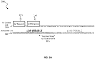
- FIG. 2A depicts an exemplary frame exchange timing diagram 200 initiated by an AP for enabling a disabled link 210 according to embodiments of the present invention.
- the frame exchange 200 includes a request 215 to enable the disabled link 210 carried over an enabled link 205.
- the enabled link 205 and the disabled link 210 transmit over different bands (e.g., 2.4 GHz, 5 GHz, 6 GHz, etc.)
- the AP sends request frame 215 carrying link IDs and an ENABLE flags to the STA to enable one or more disabled links.
- the frame can also carry operational parameter update information for the links.
- the STA can follow AP's request to enable some or all of the identified links.
- the STA determines operational parameter updates for the link or links to be enabled (if any).
- the STA sends a response frame 220 to the AP to indicate which link or links will be enabled (if any), and for each link, the frame can include a new delay defining the required delay 225 for enabling a respective link.
- the STA shall enable the link after a certain delay.
- An initial delay for the link may be negotiated between the AP and the STA and defined in the operating parameters of the link. If the response frame 220 does not carry delay information for the link, the AP and the STA can use the link after the negotiated delay of the operational parameters. If the response frame 220 indicates a new delay for the link, the AP and the STA can use the link after the new delay indicated in the response frame 220.
- the STA sends response frame 220 to the AP indicating that the AP's request has been denied.
- the frame exchange described above is implemented via an enabled link, and the AP and the STA update the status (enabled/disabled) of the links accordingly.
- the exemplary frame exchange 200 can be initiated by an AP to disable one or more enabled links according to embodiments of the present invention.
- the request frame 215 transmitted by the AP includes link IDs and DISABLE flags for requesting disablement of an enabled link or links.
- the STA can agree to disable all or some of the identified links, and the STA sends a response frame 220 carrying link IDs of the links to be disabled to the AP. Accordingly, the AP stops transmitting to the STA over the links indicated in the response frame 220, and the STA stops transmitting to the AP over the links indicated in the response frame 220 after sending the response frame 220 to AP. If the STA disagrees to disable the links identified in the request frame 215, the STA sends a response frame 220 to the AP denying the request. In this case, the STA and the AP can continue transmitting over the identified links.
- the information of the frame exchange timing diagram 200 described above for disabling a link or links is transmitted over an enabled link.
- the AP and the STA update the status (enabled/disabled) of each link accordingly.
- Link enablement and disablement initiated by an AP can be implemented in the same request frame (e.g., request frame 215) and the response frame (e.g., response frame 220) can also agree/disagree with both the enablement request and the disablement request at the same time.
- Link enablement and/or disablement frame exchange can also be initiated by an STA associated with an AP.
- Figure 2B depicts an exemplary frame exchange timing diagram timing diagram 250 initiated by an STA for enabling a disabled link 260 according to embodiments of the present invention.
- the STA sends a request frame 265 carrying link IDs and ENABLE flags to the AP to request enablement of a disabled link or links (e.g., disabled link 260).
- the request frame 265 may also carry operational parameter update information of each link.
- the AP sends a response frame 270 to the STA to confirm which requested links will be enabled. After receiving the response frame 270, for each link to be enabled, the STA enables the link using the updated operational parameters carried in the request frame 265, if any.
- the AP updates the operational parameters of the link and after a delay 275, AP and STA can transmit over the enabled link.
- the delay 275 can be the delay initially negotiated between the AP and the STA, or a new delay identified in the updated operational parameters carried in the request frame 265.
- the frame exchange 250 described above is transmitted over an enabled link 255 associated with the AP and the STA.
- the exemplary frame exchange 250 can also be used by the STA to initiate disablement of an enabled link or links according to embodiments of the present invention.
- the STA sends a request frame 265 carrying link IDs and DISABLE flags to the AP to request disablement of an enabled link or links.
- the AP sends a response frame to the STA to confirm which links will be disabled (if any), and for each link to be disabled, the AP stops transmitting to the STA over the respective link after sending the response frame 270 to the STA.
- the above frame exchange 250 is transmitted over the enabled link 255.
- Link enablement and disablement initiated by an STA can be implemented using a single request frame (e.g., request frame 265), and the response frame (e.g., response frame 270) can confirm both the enablement request and the disablement request at the same time.
- FIG 3 is a block diagram that depicts an exemplary link switch operation between an AP 305 and an STA 350 for MLO according to embodiments of the present invention.
- the AP 305 can communicate wirelessly over 3 wireless links (Link 0 (310), Link 1 (315), and Link 2 (320)), and the STA 350 can communicate wirelessly over 2 wireless links (Link 3 (355) and Link 4 (360)).
- a link e.g., between the AP's Link 1 (315) and the STA's Link 4 (360)
- the AP can request to switch to another link that is available on the AP side and then begin MLO.
- the AP can request to switch to a link between the AP's Link 2 (320) and the STA's Link 4 (360).
- the AP transmits a request frame 415 that carries the link ID and an enable FLAG as well as information regarding the target link 425 to switch to, such as the link ID and Operation BW of the target link to perform link switching frame exchange 400.
- the STA can agree or disagree with the request. If the STA agrees it sends a response frame 420 to the AP carrying a required delay 430 of the link switch and switches from the specified link 410 to the target link 425 identified in the request frame 415. Enabled link 410 is disabled and the identified link 425 is enabled after a delay 430.
- the frame exchange 400 is transmitted over an enabled link (e.g., link 405).
- an exemplary link TWT element frame exchange 500 for configuring the TWT operation of a target link 510 using an enabled link 505 is depicted according to embodiments of the present invention.
- TWT negotiation is performed between the AP and the STA. Specifically, a TWT Element 515 including the target link ID is transmitted from the AP to the STA, and the STA transmits a TWT Element 520 confirming or denying the AP's request. If the negotiation is successful, the TWT element for the target link is updated to include the link ID of target link 510. The target link then operates using the updated TWT.
- the TWT Wake time interval 540 for the target link 510 defines active and inactive period for the target link 510.
- the target link 510 is active during TWT Service Periods 530 and 535, and the target link 510 is inactive outside of the TWT Service Periods 530 and 535.
- the TWT element may carry operation parameters for multiple links, including the link that carries the frame exchange including the TWT element.
- an STA in non-AP Multi-Link Logical Entity (MLLE) capable of multi-link operation negotiates TWT parameters with the AP in AP MLLE for the current link and for other link at the same time.
- An STA in non-AP MLLE can negotiate TWT parameters for other links at the same time via a single TWT negotiation. It is assumed that the APs can maintain timing synchronization across the links.
- all enable, disable, link switch, and power save mode setup frame exchanges may be transmitted over a dedicated control link that always remains enabled.
- Other available links are used as assistant links that can be dynamically enabled and disabled.
- the control link traffic is not limited to frames of link enable, disable, link switch, and power save mode setup. In other words, regular data traffic can also be transmitted over the control link.
- Figure 6 depicts an exemplary data format element 600 for providing response or request information for selectively enabling and disabling links according to embodiments of the present invention.
- Serial ID field 605 has a length of 5 bits and indicates the ID of the request as assigned by the requester.
- the response frame transmitted in response to the request includes the same ID in Serial ID field 605.
- Control field 610 has a length of 3 bits and indicates if the element 600 is:
- Sub-elements fields 700, 710, and 720 of Figure 7 each include a sub-element ID field 750 having a length of 4 bits that indicates the type/function of the sub-element.
- data format sub-element field 700 enables/disables a target link
- sub-element field 710 enables/disables a target link and updates operating parameters of the target link
- sub-element field 720 switches a target link to a target channel and updates operating parameters of the target link.
- the link ID field 755 has a length of 4 and indicates the target link for enabling, disabling, and/or configuring the operating parameters of the target link.
- the target channel field 760 has a length of 8 bits and indicates the target channel for performing a channel switch for the target link.
- Required delay field 765 has a length of 16 bits and indicates the delay required before enabling the target link.
- Operational BW field 770 has a length of 4 bits and indicates the operating bandwidths of the target link.
- Primary band field 775 has a length of 4 bits and indicates the primary operating band of the target link.
- Supported NSS field 780 has a length of 4 bits and indicates the number of spatial streams supported by the target link.
- FIG. 8 a flow chart of an exemplary sequence of computer implemented steps of a process 800 for selectively enabling a wireless link is depicted according to embodiments of the present invention.
- a request frame is transmitted from a first wireless device to a second wireless device with a link ID and enable flag indicating a request to enable the target wireless link.
- a response frame is received from the second wireless device at the first wireless device.
- the target wireless link is enabled when the response frame confirms the request to enable the target wireless link.
- the operating parameters of the target link are updated using updated operating parameters carried in the request frame.
- FIG. 9 a flow chart depicting an exemplary sequence of computer implemented steps of a process 900 for selectively disabling a wireless link is depicted according to embodiments of the present invention.
- a request frame is transmitted from a first wireless device to a second wireless device with a link ID and disable flag indicating a request to disable the target wireless link.
- a response frame is received from the second wireless device at the first wireless device.
- the target wireless link is disabled when the response frame confirms the request to disable the target wireless link.
- FIG. 10 a flow chart of an exemplary sequence of computer implemented steps of a process 1000 for switching from a first wireless link to a second wireless link for performing MLO between a first wireless device and a second wireless device are shown according to embodiments of the present invention.
- a request frame is transmitted from a first wireless device to a second wireless device with a first link ID, a second link ID, and an enable flag indicating a request to enable the second wireless link.
- a response frame is received from the second wireless device at the first wireless device.
- the second wireless link is enabled when the response frame confirms the request to enable the second wireless link.
- the operating parameters of the second wireless link are updated using updated operating parameters carried in the request frame.
- step 1025 data is transmitted between the first wireless device and the second wireless device using the second wireless link for MLO after a required delay.
- the present invention may be drawn to electronic systems for performing power management for cooperative multi-band operations in a wireless network.
- the following discussion describes one such exemplary electronic system or computer system can be used as a platform for implementing embodiments of the present invention.
- the exemplary computer system 1112 (e.g., a multi-band cooperative wireless access point AP or a multi-band cooperative wireless station STA) includes a central processing unit (CPU) 1101 for running software applications and optionally an operating system.
- Random access memory 1102 and read-only memory 1103 store applications and data for use by the CPU 1101.
- Data storage device 1104 provides non-volatile storage for applications and data and may include fixed disk drives, removable disk drives, flash memory devices, and CD-ROM, DVD-ROM or other optical storage devices.
- the optional user inputs 1106 and 1107 comprise devices that communicate inputs from one or more users to the computer system 1112 (e.g., mice, joysticks, cameras, touch screens, and/or microphones).
- a communication or network interface 1108 includes a plurality of transceivers and allows the computer system 1112 to communicate with other computer systems, networks, or devices via an electronic communications network, including wired and/or wireless communication and including an Intranet or the Internet (e.g., 802.11 wireless standard).
- the communication or network interface 1108 can operate multiple transceivers simultaneously e.g., Transceiver 1 and Transceiver 2.
- the communication or network interface 1108 can further include a cooperative management unit for coordinating the data sent and/or received by the transceivers.
- the communication or network interface 1108 and can include a dual band interface that can operate in multiple bands simultaneously, such as 2.4 GHz, 5 GHz, and/or 6 GHz. Link management operations are performed by an AP or non-AP STA to control the status (e.g., active or doze) of specific links/bands, for example, to conserve power or increase peak throughput between devices.
- the optional display device 1110 may be any device capable of displaying visual information in response to a signal from the computer system 1112 and may include a flat panel touch sensitive display, for example.
- the components of the computer system 1112, including the CPU 1101, memory 1102/1103, data storage 1104, user input devices 1106, and graphics subsystem 1105 may be coupled via one or more data buses 1100.
- program modules include routines, programs, objects, components, data structures, etc. that perform particular tasks or implement particular abstract data types.
- functionality of the program modules may be combined or distributed as desired in various embodiments.
Landscapes
- Engineering & Computer Science (AREA)
- Computer Networks & Wireless Communication (AREA)
- Signal Processing (AREA)
- Mobile Radio Communication Systems (AREA)
- Radio Relay Systems (AREA)
Abstract
Description
- This application claims the benefit of and priority to provisional patent application Serial Number
62/769,023 - Embodiments of the present invention generally relate to the field of wireless communications. More specifically, embodiments of the present invention relate to systems and methods for managing the operation of wireless devices for multi-link communication over a wireless network.
- Modem electronic devices typically send and receive data with other electronic devices wirelessly using Wi-Fi, and many of these devices are "dual band" devices that include at least two wireless transceivers capable of operating in different frequency bands e.g., 2.4 GHz and 5 GHz. In most cases, a wireless device will communicate over only a single band at a time. For example, older and low-power devices e.g., battery powered devices, often operate on the 2.4 GHz band. Newer devices and devices that require greater bandwidth often operate on the 5 GHz band.
- However, in some cases, the use of a single band may not satisfy the bandwidth needs of certain devices. Therefore, some developing approaches to wireless communication increase communication bandwidth by operating on multiple bands concurrently, and can control which wireless device or devices can use the multiple bands, for example, based on current network traffic. This approach may be referred to as Multi-link Operation (MLO). What is needed is an approach to MLO for wireless networks that can selectively enable and disable links, for example, to reduce power consumption when there is no urgent data to exchange or the amount of traffic in the network is little, or to improve peak throughput and connection stability between wireless devices.
- Accordingly, the present invention provides a method and apparatus for simultaneous transmission and reception of data wirelessly using different wireless bands. The multi-link operations described herein can provide higher network throughput and improved network flexibility compared to traditional techniques to wireless communication. Link management operations such as enabling and disabling of a link may be performed by an AP or STA by sending a frame over a link that is currently active. Moreover, an AP may request a switch to a different link available on the AP side for MLO, for example, when a link is occupied by interference and is not available when AP needs to use the link, and the operating parameters of a target link can be updated.
- The accompanying drawings, which are incorporated in and form a part of this specification, illustrate embodiments of the invention and, together with the description, serve to explain the principles of the invention:
-
Figure 1 is a block diagram of an exemplary wireless communication system or network including a multi-band cooperative AP and a multi-band cooperative STA depicted according to embodiments of the present invention. -
Figure 2A depicts an exemplary frame exchange initiated by an AP for enabling a disabled link according to embodiments of the present invention. -
Figure 2B depicts an exemplary frame exchange initiated by an STA for enabling a disabled link according to embodiments of the present invention. -
Figure 3 depicts an exemplary link switch operation between an AP and an STA for MLO according to embodiments of the present invention. -
Figure 4 depicts an exemplary timing diagram of a frame exchange initiated by an AP for enabling a link and switching to the link according to embodiments of the present invention. -
Figure 5 depicts a timing diagram of an exemplary link TWT element frame exchange for configuring the TWT operation of a target link using an enabled link according to embodiments of the present invention. -
Figure 6 depicts an exemplary element for providing response or request information for selectively enabling and disabling links according to embodiments of the present invention. -
Figure 7 depicts exemplary sub-element fields of an element to provide information for selectively enabling and disabling links and optionally configuring operational parameters of a link according to embodiments of the present invention. -
Figure 8 is a flow chart depicting an exemplary sequence of computer implemented steps for selectively enabling a wireless link according to embodiments of the present invention. -
Figure 9 is a flow chart depicting an exemplary sequence of computer implemented steps for selectively disabling a wireless link according to embodiments of the present invention. -
Figure 10 is a flow chart depicting an exemplary sequence of computer implemented steps for selectively enabling a wireless link and switching to the link according to embodiments of the present invention. -
Figure 11 is a block diagram of an exemplary computer system platform upon which embodiments of the present invention may be implemented. - Reference will now be made in detail to several embodiments. While the subject matter will be described in conjunction with the alternative embodiments, it will be understood that they are not intended to limit the claimed subject matter to these embodiments. On the contrary, the claimed subject matter is intended to cover alternative, modifications, and equivalents, which may be included within the spirit and scope of the claimed subject matter as defined by the appended claims.
- Furthermore, in the following detailed description, numerous specific details are set forth in order to provide a thorough understanding of the claimed subject matter. However, it will be recognized by one skilled in the art that embodiments may be practiced without these specific details or with equivalents thereof. In other instances, well-known methods, procedures, components, and circuits have not been described in detail as not to unnecessarily obscure aspects and features of the subject matter.
- Portions of the detailed description that follows are presented and discussed in terms of a method. Although steps and sequencing thereof are disclosed in a figure herein (e.g.,
Figures 8 ,9 , and10 ) describing the operations of this method, such steps and sequencing are exemplary. Embodiments are well suited to performing various other steps or variations of the steps recited in the flowchart of the figure herein, and in a sequence other than that depicted and described herein. - Some portions of the detailed description are presented in terms of procedures, steps, logic blocks, processing, and other symbolic representations of operations on data bits that can be performed on computer memory. These descriptions and representations are the means used by those skilled in the data processing arts to most effectively convey the substance of their work to others skilled in the art. A procedure, computer-executed step, logic block, process, etc., is here, and generally, conceived to be a self-consistent sequence of steps or instructions leading to a desired result. The steps are those requiring physical manipulations of physical quantities. Usually, though not necessarily, these quantities take the form of electrical or magnetic signals capable of being stored, transferred, combined, compared, and otherwise manipulated in a computer system. It has proven convenient at times, principally for reasons of common usage, to refer to these signals as bits, values, elements, symbols, characters, terms, numbers, or the like.
- It should be borne in mind, however, that all of these and similar terms are to be associated with the appropriate physical quantities and are merely convenient labels applied to these quantities. Unless specifically stated otherwise as apparent from the following discussions, it is appreciated that throughout, discussions utilizing terms such as "accessing," "writing," "including," "storing," "transmitting," "associating," "identifying," "encoding," or the like, refer to the action and processes of a computer system, or similar electronic computing device, that manipulates and transforms data represented as physical (electronic) quantities within the computer system's registers and memories into other data similarly represented as physical quantities within the computer system memories or registers or other such information storage, transmission or display devices.
- As used herein, the term "EHT" may refer to a recent generation of wireless communication (Wi-Fi) known as Extremely High Throughput (EHT) and is defined according to the IEEE 802.11be standards. The term station (STA) may refer to an electronic device capable of sending and receiving data over Wi-Fi that is not operating as an access point (AP).
- Embodiments of the present invention provide a method and apparatus for simultaneous transmission and reception of data wirelessly using different wireless bands. The multi-link operations described herein can provide higher network throughput and improved network flexibility compared to traditional techniques to wireless communication. Link management operations such as enabling and disabling of a link may be performed by an AP or STA by sending a frame over a link that is currently active. Moreover, an AP may request a switch to a different link available on the AP side for MLO, for example, when a link is occupied by interference and is not available when AP needs to use the link, and the operating parameters of a target link can be updated.
- According to the present invention, when a link is enabled, both the AP and STA may be aware of the link's enabled status. The link can be active, in a power-save mode, or following target wake time (TWT) operations for a doze/service period. An enabled link can be disabled through a frame exchange initiated by the AP or STA over an enabled link. When a link is disabled, the AP and STA both are aware of the link's disabled status. In this case, the AP shall not send frames to the STA in the link and the STA shall not send frames to AP in the link. A disabled link can be enabled through a frame exchange initiated by the AP or STA over an enabled link.
- In general, according to the present invention, N links may operate over different RF bands. Links can be selectively enabled or disabled via a frame exchange over an active link. The frame exchange for enabling a link can include operation parameters for configuring the link. An STA's power save operations, such as TWT, for a specific link can be negotiated through a frame exchange over an enabled link. Moreover, a link can be switched to a different RF band via the frame exchange over the enabled link.
- The specific capabilities and operational parameters of each link are negotiated during association, and the parameters can be updated through a frame exchange when the link is enabled. For example, when an STA associates with an AP, the capabilities and operational parameters of each link are negotiated and are configured accordingly after successful association. The capabilities may include, for example, RF bands (2.4G, 5G, 6G), Number of Spatial Streams (NSS), bandwidth (e.g., 20 MHz, 40 MHz, etc.), and a station type (EHT, HE, VHT, or HT STA). The operational parameters can include, for example, Link ID, primary band and operation BW of the link, a required delay from disabled status to enabled status, and a required delay for switching channels.
- With regard to
Figure 1 , an exemplarywireless communication system 100 including a multi-bandcooperative AP 105 and a multi-bandcooperative STA 155 is depicted according to embodiments of the present invention. The multi-bandcooperative AP 105 includes a 5 GHz transceiver 110 and a 2.4GHz transceiver 115. Other types of transceivers that operate on different bands, such as 6 GHz and above, can also be used by the multi-bandcooperative AP 105 according to embodiments of the present invention. Thetransceivers 110 and 115 ofAP 105 exchange data and information withcooperative management unit 120 that coordinates information sent and/or received bytransceivers 110 and 115. - The multi-band
cooperative ST 155 includes a 5GHz transceiver 160 and a 2.4GHz transceiver 165. Other types of transceivers that operate on different bands, such as 6 GHz and above, can also be used by the multi-bandcooperative STA 155 according to some embodiments of the present invention. Thetransceivers STA 155 exchange data and information withcooperative management unit 170 that coordinates information sent and received bytransceivers - The multi-band
cooperative AP 105 and the multi-bandcooperative STA 155 have simultaneous transmission and reception capability for communicating using different wireless bands. The transmitters operating on the different bands can perform independent clear channel assessments (CCAs) using joint or intendent transmissions. Moreover, full duplex communication can be enabled by independent multi-band operation using FDD mode. - The
STA 155 can access channels in multiple bands independently. For example, after receiving an enhanced distributed channel access (EDCA) transmission opportunity (TXOP) frame, theSTA 155 can begin transmitting frames over the respective band during the window of time provided in the EDCA TXOP frame. When theSTA 155 receives EDCA TXOP frames in multiple bands simultaneously, theSTA 155 can transmit frames using multiple bands simultaneously during the provided window of time. - The
STA 155 transmitting frames using multiple bands simultaneously can mitigate delay and improve peak throughput of theSTA 155. However, in some cases, transmitting frames using multiple bands simultaneously can degrade the performance of the basic service set (BSS) comprising theSTA 155. For example, the performance of the BSS can be degraded when theSTA 155 operating on multiple bands simultaneously uses a substantial amount of the bandwidth available to the BSS due to the increased traffic. Therefore, theAP 105 can control which STAs are granted multi-band channel access, and the access can be terminated by the AP at any time, for example, based on changing network conditions or requirements, or to conserve power when the amount of traffic to be transmitted is relatively low. In other words, depending on certain conditions, such as traffic load, a non-AP STA may use fewer than all supported/available links in order to reduce energy consumption. - According to the present invention, an AP and an associated STA may both be aware of the availability of every link. The AP can send a request to the STA to enable links that are currently disabled. The STA can agree to enable the link or links, partially agree, or disagree with the request. The AP can send a request to STA to disable links if the AP will no longer use the links for downstream traffic. The STA can agree to disable the link or links, partially agree, or disagree with the request. The STA can enable disabled links and sends a notice to the AP indicating that the links have been enabled. The STA can also disable enabled links send a notice to the AP indicating that the links have been disabled. The
frame exchange 200 for enabling or disabling a link or links is transmitted over a currently enabled link associated with the AP and the STA. -
Figure 2A depicts an exemplary frame exchange timing diagram 200 initiated by an AP for enabling adisabled link 210 according to embodiments of the present invention. Theframe exchange 200 includes arequest 215 to enable thedisabled link 210 carried over anenabled link 205. Theenabled link 205 and thedisabled link 210 transmit over different bands (e.g., 2.4 GHz, 5 GHz, 6 GHz, etc.) Specifically, the AP sendsrequest frame 215 carrying link IDs and an ENABLE flags to the STA to enable one or more disabled links. The frame can also carry operational parameter update information for the links. In response to therequest frame 215, the STA can follow AP's request to enable some or all of the identified links. In this case, the STA determines operational parameter updates for the link or links to be enabled (if any). The STA sends aresponse frame 220 to the AP to indicate which link or links will be enabled (if any), and for each link, the frame can include a new delay defining the requireddelay 225 for enabling a respective link. - As indicated above, for each link that is to be enabled, the STA shall enable the link after a certain delay. An initial delay for the link may be negotiated between the AP and the STA and defined in the operating parameters of the link. If the
response frame 220 does not carry delay information for the link, the AP and the STA can use the link after the negotiated delay of the operational parameters. If theresponse frame 220 indicates a new delay for the link, the AP and the STA can use the link after the new delay indicated in theresponse frame 220. - Otherwise, if the STA does not agree to enable the identified link or links, the STA sends
response frame 220 to the AP indicating that the AP's request has been denied. In either case, the frame exchange described above is implemented via an enabled link, and the AP and the STA update the status (enabled/disabled) of the links accordingly. - Still with regard to
Figure 2A , theexemplary frame exchange 200 can be initiated by an AP to disable one or more enabled links according to embodiments of the present invention. In this case, therequest frame 215 transmitted by the AP includes link IDs and DISABLE flags for requesting disablement of an enabled link or links. The STA can agree to disable all or some of the identified links, and the STA sends aresponse frame 220 carrying link IDs of the links to be disabled to the AP. Accordingly, the AP stops transmitting to the STA over the links indicated in theresponse frame 220, and the STA stops transmitting to the AP over the links indicated in theresponse frame 220 after sending theresponse frame 220 to AP. If the STA disagrees to disable the links identified in therequest frame 215, the STA sends aresponse frame 220 to the AP denying the request. In this case, the STA and the AP can continue transmitting over the identified links. - The information of the frame exchange timing diagram 200 described above for disabling a link or links is transmitted over an enabled link. The AP and the STA update the status (enabled/disabled) of each link accordingly. Link enablement and disablement initiated by an AP can be implemented in the same request frame (e.g., request frame 215) and the response frame (e.g., response frame 220) can also agree/disagree with both the enablement request and the disablement request at the same time.
- Link enablement and/or disablement frame exchange can also be initiated by an STA associated with an AP.
Figure 2B depicts an exemplary frame exchange timing diagram timing diagram 250 initiated by an STA for enabling adisabled link 260 according to embodiments of the present invention. For instance, the STA sends arequest frame 265 carrying link IDs and ENABLE flags to the AP to request enablement of a disabled link or links (e.g., disabled link 260). Therequest frame 265 may also carry operational parameter update information of each link. The AP sends aresponse frame 270 to the STA to confirm which requested links will be enabled. After receiving theresponse frame 270, for each link to be enabled, the STA enables the link using the updated operational parameters carried in therequest frame 265, if any. The AP updates the operational parameters of the link and after adelay 275, AP and STA can transmit over the enabled link. Thedelay 275 can be the delay initially negotiated between the AP and the STA, or a new delay identified in the updated operational parameters carried in therequest frame 265. Theframe exchange 250 described above is transmitted over anenabled link 255 associated with the AP and the STA. - Still with regard to
Figure 2B , theexemplary frame exchange 250 can also be used by the STA to initiate disablement of an enabled link or links according to embodiments of the present invention. The STA sends arequest frame 265 carrying link IDs and DISABLE flags to the AP to request disablement of an enabled link or links. The AP sends a response frame to the STA to confirm which links will be disabled (if any), and for each link to be disabled, the AP stops transmitting to the STA over the respective link after sending theresponse frame 270 to the STA. The STA stops transmitting to the AP over the disabled link or links after receiving theresponse frame 270 from the AP. Theabove frame exchange 250 is transmitted over theenabled link 255. Link enablement and disablement initiated by an STA can be implemented using a single request frame (e.g., request frame 265), and the response frame (e.g., response frame 270) can confirm both the enablement request and the disablement request at the same time. -
Figure 3 is a block diagram that depicts an exemplary link switch operation between anAP 305 and anSTA 350 for MLO according to embodiments of the present invention. As depicted inFigure 3 , theAP 305 can communicate wirelessly over 3 wireless links (Link 0 (310), Link 1 (315), and Link 2 (320)), and theSTA 350 can communicate wirelessly over 2 wireless links (Link 3 (355) and Link 4 (360)). When a link, e.g., between the AP's Link 1 (315) and the STA's Link 4 (360), is occupied by interference or is otherwise unavailable when an AP needs to use the link, the AP can request to switch to another link that is available on the AP side and then begin MLO. For example, as depicted inFigure 3 , the AP can request to switch to a link between the AP's Link 2 (320) and the STA's Link 4 (360). - As depicted in the timing diagram of
Figure 4 , according to embodiments of the present invention, the AP transmits arequest frame 415 that carries the link ID and an enable FLAG as well as information regarding thetarget link 425 to switch to, such as the link ID and Operation BW of the target link to perform link switchingframe exchange 400. The STA can agree or disagree with the request. If the STA agrees it sends aresponse frame 420 to the AP carrying a required delay 430 of the link switch and switches from the specifiedlink 410 to thetarget link 425 identified in therequest frame 415.Enabled link 410 is disabled and the identifiedlink 425 is enabled after a delay 430. If the STA disagrees, it sends a response frame denying the AP's request, and the STA waits for another request from the AP. In this case, the identified link remains disabled. Theframe exchange 400 is transmitted over an enabled link (e.g., link 405). - With regard to the timing diagram of
Figure 5 , an exemplary link TWTelement frame exchange 500 for configuring the TWT operation of atarget link 510 using anenabled link 505 is depicted according to embodiments of the present invention. TWT negotiation is performed between the AP and the STA. Specifically, aTWT Element 515 including the target link ID is transmitted from the AP to the STA, and the STA transmits aTWT Element 520 confirming or denying the AP's request. If the negotiation is successful, the TWT element for the target link is updated to include the link ID oftarget link 510. The target link then operates using the updated TWT. For example, as depicted inFigure 5 , the TWTWake time interval 540 for thetarget link 510 defines active and inactive period for thetarget link 510. Specifically, thetarget link 510 is active duringTWT Service Periods target link 510 is inactive outside of theTWT Service Periods - According to the present invention, the TWT element may carry operation parameters for multiple links, including the link that carries the frame exchange including the TWT element.
- According to embodiments of the present invention, an STA in non-AP Multi-Link Logical Entity (MLLE) capable of multi-link operation negotiates TWT parameters with the AP in AP MLLE for the current link and for other link at the same time. An STA in non-AP MLLE can negotiate TWT parameters for other links at the same time via a single TWT negotiation. It is assumed that the APs can maintain timing synchronization across the links.
- According to the present invention, all enable, disable, link switch, and power save mode setup frame exchanges may be transmitted over a dedicated control link that always remains enabled. Other available links are used as assistant links that can be dynamically enabled and disabled. The control link traffic is not limited to frames of link enable, disable, link switch, and power save mode setup. In other words, regular data traffic can also be transmitted over the control link.
-
Figure 6 depicts an exemplarydata format element 600 for providing response or request information for selectively enabling and disabling links according to embodiments of the present invention.Serial ID field 605 has a length of 5 bits and indicates the ID of the request as assigned by the requester. The response frame transmitted in response to the request includes the same ID inSerial ID field 605.Control field 610 has a length of 3 bits and indicates if theelement 600 is: - A Request;
- A response with rejection that rejects all link enable/disable requests in the corresponding request frame;
- A response with acceptance that accepts all link enable/disable requests in the corresponding request frame; or
- A response with partial acceptance accepting some requests in the corresponding request frame.
- With regard to
Sub-elements fields Figure 7 , each include asub-element ID field 750 having a length of 4 bits that indicates the type/function of the sub-element. For example, data formatsub-element field 700 enables/disables a target link,sub-element field 710 enables/disables a target link and updates operating parameters of the target link, andsub-element field 720 switches a target link to a target channel and updates operating parameters of the target link. - The
link ID field 755 has a length of 4 and indicates the target link for enabling, disabling, and/or configuring the operating parameters of the target link. Thetarget channel field 760 has a length of 8 bits and indicates the target channel for performing a channel switch for the target link. Requireddelay field 765 has a length of 16 bits and indicates the delay required before enabling the target link.Operational BW field 770 has a length of 4 bits and indicates the operating bandwidths of the target link.Primary band field 775 has a length of 4 bits and indicates the primary operating band of the target link. SupportedNSS field 780 has a length of 4 bits and indicates the number of spatial streams supported by the target link. - With regard to
Figure 8 , a flow chart of an exemplary sequence of computer implemented steps of aprocess 800 for selectively enabling a wireless link is depicted according to embodiments of the present invention. - At
step 805, a request frame is transmitted from a first wireless device to a second wireless device with a link ID and enable flag indicating a request to enable the target wireless link. - At
step 810, a response frame is received from the second wireless device at the first wireless device. - At
step 815, the target wireless link is enabled when the response frame confirms the request to enable the target wireless link. - Optionally, at
step 820, the operating parameters of the target link are updated using updated operating parameters carried in the request frame. - With regard to
Figure 9 , a flow chart depicting an exemplary sequence of computer implemented steps of aprocess 900 for selectively disabling a wireless link is depicted according to embodiments of the present invention. - At
step 905, a request frame is transmitted from a first wireless device to a second wireless device with a link ID and disable flag indicating a request to disable the target wireless link. - At
step 910, a response frame is received from the second wireless device at the first wireless device. - At
step 915, the target wireless link is disabled when the response frame confirms the request to disable the target wireless link. - With regard to
Figure 10 , a flow chart of an exemplary sequence of computer implemented steps of aprocess 1000 for switching from a first wireless link to a second wireless link for performing MLO between a first wireless device and a second wireless device are shown according to embodiments of the present invention. - At
step 1005, a request frame is transmitted from a first wireless device to a second wireless device with a first link ID, a second link ID, and an enable flag indicating a request to enable the second wireless link. - At
step 1010, a response frame is received from the second wireless device at the first wireless device. - At
step 1015, the second wireless link is enabled when the response frame confirms the request to enable the second wireless link. - Optionally, at
step 1020, the operating parameters of the second wireless link are updated using updated operating parameters carried in the request frame. - At
step 1025, data is transmitted between the first wireless device and the second wireless device using the second wireless link for MLO after a required delay. - The present invention may be drawn to electronic systems for performing power management for cooperative multi-band operations in a wireless network. The following discussion describes one such exemplary electronic system or computer system can be used as a platform for implementing embodiments of the present invention.
- In the example of
Figure 11 , the exemplary computer system 1112 (e.g., a multi-band cooperative wireless access point AP or a multi-band cooperative wireless station STA) includes a central processing unit (CPU) 1101 for running software applications and optionally an operating system.Random access memory 1102 and read-only memory 1103 store applications and data for use by theCPU 1101.Data storage device 1104 provides non-volatile storage for applications and data and may include fixed disk drives, removable disk drives, flash memory devices, and CD-ROM, DVD-ROM or other optical storage devices. Theoptional user inputs - A communication or
network interface 1108 includes a plurality of transceivers and allows thecomputer system 1112 to communicate with other computer systems, networks, or devices via an electronic communications network, including wired and/or wireless communication and including an Intranet or the Internet (e.g., 802.11 wireless standard). The communication ornetwork interface 1108 can operate multiple transceivers simultaneously e.g.,Transceiver 1 andTransceiver 2. The communication ornetwork interface 1108 can further include a cooperative management unit for coordinating the data sent and/or received by the transceivers. The communication ornetwork interface 1108 and can include a dual band interface that can operate in multiple bands simultaneously, such as 2.4 GHz, 5 GHz, and/or 6 GHz. Link management operations are performed by an AP or non-AP STA to control the status (e.g., active or doze) of specific links/bands, for example, to conserve power or increase peak throughput between devices. - The
optional display device 1110 may be any device capable of displaying visual information in response to a signal from thecomputer system 1112 and may include a flat panel touch sensitive display, for example. The components of thecomputer system 1112, including theCPU 1101,memory 1102/1103,data storage 1104,user input devices 1106, and graphics subsystem 1105 may be coupled via one ormore data buses 1100. - Some embodiments may be described in the general context of computer-executable instructions, such as program modules, executed by one or more computers or other devices. Generally, program modules include routines, programs, objects, components, data structures, etc. that perform particular tasks or implement particular abstract data types. Typically the functionality of the program modules may be combined or distributed as desired in various embodiments.
- Embodiments of the present invention are thus described. While the present invention has been described in particular embodiments, it should be appreciated that the present invention should not be construed as limited by such embodiments, but rather construed according to the following claims.
Claims (15)
- A method of selectively enabling a target wireless link operable to provide communication between a first wireless device and a second wireless device during multi-link operation (MLO), the method comprising:transmitting a request frame from the first wireless device to the second wireless device, the request frame comprising a link ID of the target wireless link and an enable flag indicating a request to enable the target wireless link;receiving a response frame from the second wireless device at the first wireless device; andenabling the target wireless link by using the first wireless device when the response frame confirms the request to enable the target wireless link.
- The method of Claim 1, wherein the first wireless device comprises a wireless access point (AP) and the second wireless device comprises a wireless station (STA).
- The method of Claim 2, wherein the request frame comprises link IDs of a plurality of target wireless links, and wherein the response frame indicates link IDs of a subset of the plurality of target wireless links that will be enabled.
- The method of Claim 2, wherein the response frame denies the request to enable the target wireless link.
- The method of Claim 1, wherein the request frame comprises updated operating parameters for the target link and further comprising updating the operating parameters of the target link using the updated operating parameters.
- The method of Claim 1, wherein the request frame and the response frame are both transmitted over a currently enabled link,
wherein in particular the currently enabled link comprises a dedicated control link that remains enabled. - The method of Claim 1, wherein the first wireless device comprises a wireless station (STA) and the second wireless device comprises a wireless access point (AP).
- A method of selectively disabling a target wireless link between a first wireless device and a second wireless device during multi-link operation (MLO), the method comprising:transmitting a request frame from the first wireless device to the second wireless device, the request frame comprising a link ID of the target wireless link and a disable flag indicating a request to disable the target wireless link;receiving a response frame from the second wireless device at the first wireless device; anddisabling the target wireless link by using the first wireless device when the response frame confirms the request to disable the target wireless link.
- The method of Claim 8, wherein the first wireless device comprises a wireless access point (AP) and the second wireless device comprises a wireless station (STA).
- The method of Claim 9, wherein the request frame comprises link IDs of a plurality of target wireless links, and wherein the response frame indicates link IDs of a subset of the plurality of target wireless links that will be disabled.
- The method of Claim 8, wherein the response frame denies the request to disable the target wireless link, and/or
wherein the disabling the target wireless link comprises ceasing transmission over the target wireless link after receiving the response frame, and/or
wherein the request frame and the response frame are transmitted over a currently enabled link,
wherein the currently enabled link in particular comprises a dedicated control link that remains enabled. - A method of setting up a target wake time (TWT) operation for a target wireless link between a first wireless device and a second wireless device during multi-link operation (MLO), the method comprising:transmitting a request frame from the first wireless device to the second wireless device, the request frame comprising a TWT element and a link ID of the target wireless link for initiating a TWT negotiation;receiving a response frame from the second wireless device at the first wireless device for completing the TWT negotiation; andconfiguring the target wireless link by using the first wireless device based on the TWT negotiation.
- The method of Claim 12, wherein the TWT negotiation comprises performing TWT negotiation for multiple links at the same time.
- The method of Claim 12, wherein the target wireless link comprises the wireless link that carries the request frame and the response frame.
- The method of Claim 12, wherein the TWT element comprises operational parameters for the target link and further comprising updating the TWT element to include the link ID of the target link, and/or
wherein the first wireless device comprises a wireless access point (AP) and the second wireless device comprises a wireless station (STA).
Applications Claiming Priority (2)
| Application Number | Priority Date | Filing Date | Title |
|---|---|---|---|
| US201862769023P | 2018-11-19 | 2018-11-19 | |
| US16/685,917 US11153921B2 (en) | 2018-11-19 | 2019-11-15 | Method and apparatus for link enablement and disablement during multi-link operation in a wireless network |
Publications (1)
| Publication Number | Publication Date |
|---|---|
| EP3654703A1 true EP3654703A1 (en) | 2020-05-20 |
Family
ID=68610020
Family Applications (1)
| Application Number | Title | Priority Date | Filing Date |
|---|---|---|---|
| EP19209781.4A Pending EP3654703A1 (en) | 2018-11-19 | 2019-11-18 | Method and apparatus for link enablement and disablement during multi-link operation in a wireless network |
Country Status (3)
| Country | Link |
|---|---|
| US (1) | US11153921B2 (en) |
| EP (1) | EP3654703A1 (en) |
| TW (2) | TWI761727B (en) |
Cited By (8)
| Publication number | Priority date | Publication date | Assignee | Title |
|---|---|---|---|---|
| WO2022008079A1 (en) * | 2020-07-10 | 2022-01-13 | Telefonaktiebolaget Lm Ericsson (Publ) | Multi-link communication in a wireless communication network |
| WO2022028967A1 (en) * | 2020-08-04 | 2022-02-10 | Sony Group Corporation | Communication devices and methods for wireless communication in a multi link environment |
| WO2022040888A1 (en) * | 2020-08-24 | 2022-03-03 | 北京小米移动软件有限公司 | Sub-channel request method, sub-channel indication method and device |
| WO2023110796A1 (en) * | 2021-12-13 | 2023-06-22 | Canon Kabushiki Kaisha | Communication methods and device to manage eligible enhanced multi-link multi-radio links |
| EP4203601A1 (en) * | 2021-12-23 | 2023-06-28 | INTEL Corporation | Methods and arrangements for channel operation |
| GB2617367A (en) * | 2022-04-06 | 2023-10-11 | Canon Kk | Improved EMLSR mode in non-AP MLDs not triggered by the AP MLD |
| EP4149197A4 (en) * | 2020-06-05 | 2023-11-01 | Huawei Technologies Co., Ltd. | Link selection method and apparatus, and computer readable storage medium |
| EP4199600A4 (en) * | 2020-08-14 | 2024-05-08 | Beijing Xiaomi Mobile Software Co Ltd | Multi-connectivity communication method and device |
Families Citing this family (29)
| Publication number | Priority date | Publication date | Assignee | Title |
|---|---|---|---|---|
| WO2020246708A1 (en) * | 2019-06-03 | 2020-12-10 | 엘지전자 주식회사 | Method and apparatus for transmitting or receiving information relating to link in wireless lan system |
| US11665780B2 (en) * | 2019-06-07 | 2023-05-30 | Intel Corporation | Multi-link policy signaling for extremely high throughput (EHT) |
| US11510269B2 (en) * | 2019-07-01 | 2022-11-22 | Qualcomm Incorporated | Signaling for multi-link communication in a wireless local area network (WLAN) |
| US11723113B2 (en) * | 2020-01-04 | 2023-08-08 | Nxp Usa, Inc. | Apparatus and method for enabling and disabling links in multi-link communication systems |
| US11690012B2 (en) * | 2020-03-13 | 2023-06-27 | Samsung Electronics Co., Ltd. | Systems and methods for managing power usage of a multi-link device equipped with a plurality of radio interfaces |
| EP4158997A1 (en) * | 2020-05-27 | 2023-04-05 | Qualcomm Incorporated | Transitioning between multi-link and single-link mode on a transmission opportunity (txop) basis |
| US20230224814A1 (en) * | 2020-05-29 | 2023-07-13 | Lg Electronics Inc. | Power saving in nstr environment |
| CN113938983B (en) * | 2020-06-29 | 2023-02-28 | 成都极米科技股份有限公司 | Multi-link terminal, method and device for performing link exchange and storage medium |
| CN113938912A (en) * | 2020-07-13 | 2022-01-14 | 华为技术有限公司 | Data transmission method and device |
| CN116114310A (en) * | 2020-07-27 | 2023-05-12 | 日本电信电话株式会社 | Base station and terminal |
| CN114342481B (en) * | 2020-08-11 | 2024-04-09 | 北京小米移动软件有限公司 | Channel switching method and communication equipment |
| CN116233886B (en) * | 2020-08-14 | 2024-04-23 | 华为技术有限公司 | Key BSS parameter management method and related device suitable for multiple links |
| CN116234069B (en) * | 2021-01-15 | 2023-12-08 | 华为技术有限公司 | Multilink reconfiguration method and device |
| CN116566568B (en) * | 2021-04-07 | 2023-11-03 | 华为技术有限公司 | Information indication method and communication device |
| CN113141674A (en) * | 2021-04-08 | 2021-07-20 | 成都极米科技股份有限公司 | Link configuration method, device, system and storage medium in multi-link system |
| CN113141672B (en) * | 2021-04-08 | 2023-03-17 | 成都极米科技股份有限公司 | Link configuration method, device, system and storage medium in multi-link system |
| US11936473B2 (en) | 2021-04-16 | 2024-03-19 | Qualcomm Incorporated | Station performance enhancement with multi-link operations (MLO) |
| CN117528731A (en) * | 2021-05-04 | 2024-02-06 | 华为技术有限公司 | Apparatus and method for power-saving multi-link communication in wireless networks |
| WO2022236711A1 (en) * | 2021-05-11 | 2022-11-17 | 北京小米移动软件有限公司 | Communication method and communication apparatus under multiple links |
| CN115442918B (en) * | 2021-06-04 | 2024-04-30 | 成都极米科技股份有限公司 | Link switching method, device, system and storage medium in multi-link system |
| WO2022270886A1 (en) * | 2021-06-22 | 2022-12-29 | 엘지전자 주식회사 | Method and device for performing tid-to-link mapping in wireless lan system |
| US20230113355A1 (en) * | 2021-10-12 | 2023-04-13 | Mediatek Singapore Pte. Ltd. | Link Availability Indication For Non-Primary Link In Wireless Communications |
| KR20230089740A (en) * | 2021-12-14 | 2023-06-21 | 삼성전자주식회사 | Method for determining link of hub device for wireless communication and electronic device performing the method |
| CN114765901B (en) * | 2021-12-20 | 2023-05-02 | 极米科技股份有限公司 | Method, device, equipment and storage medium for managing multi-link equipment connection |
| TWI828494B (en) * | 2021-12-27 | 2024-01-01 | 日商宜麗客股份有限公司 | Repeaters for wireless LAN, routers for wireless LAN, and wireless LAN systems |
| CN116419328A (en) * | 2021-12-30 | 2023-07-11 | 中兴通讯股份有限公司 | Data transmission method and device, storage medium and electronic device |
| WO2023145006A1 (en) * | 2022-01-28 | 2023-08-03 | 日本電信電話株式会社 | Wireless device and wireless communication method |
| US11700191B1 (en) * | 2022-03-11 | 2023-07-11 | Dell Products L.P. | Packet replication for delay-sensitive traffic |
| WO2024063323A1 (en) * | 2022-09-23 | 2024-03-28 | 삼성전자주식회사 | Electronic device for supporting multi-link operation, and operation method thereof |
Citations (3)
| Publication number | Priority date | Publication date | Assignee | Title |
|---|---|---|---|---|
| US20180092039A1 (en) * | 2016-09-29 | 2018-03-29 | Laurent Cariou | Multi-band link-aggregation pre-negotiated power save modes |
| US20180206174A1 (en) * | 2017-01-19 | 2018-07-19 | Qualcomm Incorporated | Packet based link aggregation architectures |
| US20190335454A1 (en) * | 2018-07-11 | 2019-10-31 | Po-Kai Huang | Methods for multi-link setup between a multi-link access point (ap) logical entity and a multi-link non-ap logical entity |
Family Cites Families (12)
| Publication number | Priority date | Publication date | Assignee | Title |
|---|---|---|---|---|
| KR100705578B1 (en) * | 2005-07-11 | 2007-04-10 | 삼성전자주식회사 | Wireless Distribution System Repeater apparatus and method in wireless LAN system |
| US9088859B2 (en) * | 2012-09-06 | 2015-07-21 | Dell Products, Lp | Method and apparatus for connection context aware radio communication management |
| US9544782B2 (en) * | 2012-11-02 | 2017-01-10 | Qualcomm Incorporated | Systems, apparatus, and methods for range extension of wireless communication |
| US9775116B2 (en) * | 2014-05-05 | 2017-09-26 | Isco International, Llc | Method and apparatus for increasing performance of communication links of cooperative communication nodes |
| EP3035728A1 (en) * | 2014-12-16 | 2016-06-22 | Thomson Licensing | Method of selectively enabling a wireless access point or repeater |
| US20160359572A1 (en) * | 2015-03-03 | 2016-12-08 | Qualcomm Incorporated | Enabling hidden node protection procedure |
| EP3651386B1 (en) * | 2015-05-04 | 2023-08-23 | ISCO International, LLC | Method and apparatus for increasing the performance of communication paths for communication nodes |
| US10412769B2 (en) * | 2017-01-17 | 2019-09-10 | Qualcomm Incorporated | Methods and systems for cross BSS sounding |
| US10298279B2 (en) * | 2017-04-05 | 2019-05-21 | Isco International, Llc | Method and apparatus for increasing performance of communication paths for communication nodes |
| CN111316732B (en) * | 2017-09-06 | 2023-10-20 | 皇家飞利浦有限公司 | User equipment using dual beams to support multiple connections in a wireless communication network |
| CN107995184B (en) * | 2017-11-28 | 2020-10-30 | 航信德利信息系统(上海)有限公司 | Connector and communication method using same |
| US11343064B2 (en) * | 2018-05-03 | 2022-05-24 | Samsung Electronics Co., Ltd. | Systems and methods to improve co-existence between fixed wireless access and short range devices in 802.11ay |
-
2019
- 2019-11-15 US US16/685,917 patent/US11153921B2/en active Active
- 2019-11-18 EP EP19209781.4A patent/EP3654703A1/en active Pending
- 2019-11-19 TW TW108141904A patent/TWI761727B/en active
- 2019-11-19 TW TW111108696A patent/TWI777901B/en active
Patent Citations (3)
| Publication number | Priority date | Publication date | Assignee | Title |
|---|---|---|---|---|
| US20180092039A1 (en) * | 2016-09-29 | 2018-03-29 | Laurent Cariou | Multi-band link-aggregation pre-negotiated power save modes |
| US20180206174A1 (en) * | 2017-01-19 | 2018-07-19 | Qualcomm Incorporated | Packet based link aggregation architectures |
| US20190335454A1 (en) * | 2018-07-11 | 2019-10-31 | Po-Kai Huang | Methods for multi-link setup between a multi-link access point (ap) logical entity and a multi-link non-ap logical entity |
Cited By (8)
| Publication number | Priority date | Publication date | Assignee | Title |
|---|---|---|---|---|
| EP4149197A4 (en) * | 2020-06-05 | 2023-11-01 | Huawei Technologies Co., Ltd. | Link selection method and apparatus, and computer readable storage medium |
| WO2022008079A1 (en) * | 2020-07-10 | 2022-01-13 | Telefonaktiebolaget Lm Ericsson (Publ) | Multi-link communication in a wireless communication network |
| WO2022028967A1 (en) * | 2020-08-04 | 2022-02-10 | Sony Group Corporation | Communication devices and methods for wireless communication in a multi link environment |
| EP4199600A4 (en) * | 2020-08-14 | 2024-05-08 | Beijing Xiaomi Mobile Software Co Ltd | Multi-connectivity communication method and device |
| WO2022040888A1 (en) * | 2020-08-24 | 2022-03-03 | 北京小米移动软件有限公司 | Sub-channel request method, sub-channel indication method and device |
| WO2023110796A1 (en) * | 2021-12-13 | 2023-06-22 | Canon Kabushiki Kaisha | Communication methods and device to manage eligible enhanced multi-link multi-radio links |
| EP4203601A1 (en) * | 2021-12-23 | 2023-06-28 | INTEL Corporation | Methods and arrangements for channel operation |
| GB2617367A (en) * | 2022-04-06 | 2023-10-11 | Canon Kk | Improved EMLSR mode in non-AP MLDs not triggered by the AP MLD |
Also Published As
| Publication number | Publication date |
|---|---|
| US20200163141A1 (en) | 2020-05-21 |
| TW202226884A (en) | 2022-07-01 |
| TW202025848A (en) | 2020-07-01 |
| TWI777901B (en) | 2022-09-11 |
| US11153921B2 (en) | 2021-10-19 |
| TWI761727B (en) | 2022-04-21 |
Similar Documents
| Publication | Publication Date | Title |
|---|---|---|
| US11153921B2 (en) | Method and apparatus for link enablement and disablement during multi-link operation in a wireless network | |
| US11272536B2 (en) | Multi-link operation setup and channel access control | |
| US10779215B2 (en) | RF power control for dual connectivity | |
| US11751134B2 (en) | Power save and group-addressed frames in WLAN using multiple communication links | |
| US11963100B2 (en) | Method and apparatus for multi-band power management in a wireless network | |
| US11172523B2 (en) | Communication apparatus for executing service, control method and storage medium therefor, and communication system | |
| US7610018B2 (en) | Channel change procedures in a wireless communications network | |
| US20230164693A1 (en) | Configurable Power Saving Signal with Multiple Functionalities in 5G NR | |
| CN115226199A (en) | 5G New radio NAS Notification procedure | |
| US20160353470A1 (en) | Neighbor Awareness Networking Datapath - Scheduling, Scheduler Rank, and Pre-Datapath Operation Triggering | |
| CN110267330B (en) | Apparatus, system, and method for scheduling power profiles for UE power savings | |
| CN114079952B (en) | Method for transmitting small data under non-starting state and user device | |
| JP2024020535A (en) | Common analog beam steering for band group | |
| WO2014044171A1 (en) | Channel negotiation method, device, and system | |
| US20210144630A1 (en) | Base station and data transmission method thereof for mobile communication system | |
| CN105991711B (en) | Communication method, terminal and related equipment | |
| WO2019062784A1 (en) | Resource configuration method and apparatus | |
| WO2022228360A1 (en) | Communication method and apparatus | |
| WO2019095783A1 (en) | Association method, instruction method, and device for synchronization block and paging-scheduling signaling message | |
| CN114270980A (en) | Setting up different BWPs earlier by a UE in connection establishment to a wireless network when transitioning from an idle state or an inactive state | |
| US20230051808A1 (en) | Prioritized service period for time sensitive transmissions | |
| JP2002112324A (en) | Wireless communication system, connection device for the wireless communication system and wireless communication connection method | |
| WO2009056899A1 (en) | Channel change decision based on connection priority | |
| WO2023131741A1 (en) | Method for overhead reduction in nr sidelink inter-ue coordination (iuc) | |
| WO2020052309A1 (en) | Method and apparatus for determining radio access technology used by direct communication interface |
Legal Events
| Date | Code | Title | Description |
|---|---|---|---|
| PUAI | Public reference made under article 153(3) epc to a published international application that has entered the european phase |
Free format text: ORIGINAL CODE: 0009012 |
|
| STAA | Information on the status of an ep patent application or granted ep patent |
Free format text: STATUS: THE APPLICATION HAS BEEN PUBLISHED |
|
| AK | Designated contracting states |
Kind code of ref document: A1 Designated state(s): AL AT BE BG CH CY CZ DE DK EE ES FI FR GB GR HR HU IE IS IT LI LT LU LV MC MK MT NL NO PL PT RO RS SE SI SK SM TR |
|
| AX | Request for extension of the european patent |
Extension state: BA ME |
|
| STAA | Information on the status of an ep patent application or granted ep patent |
Free format text: STATUS: REQUEST FOR EXAMINATION WAS MADE |
|
| 17P | Request for examination filed |
Effective date: 20201111 |
|
| RBV | Designated contracting states (corrected) |
Designated state(s): AL AT BE BG CH CY CZ DE DK EE ES FI FR GB GR HR HU IE IS IT LI LT LU LV MC MK MT NL NO PL PT RO RS SE SI SK SM TR |
|
| STAA | Information on the status of an ep patent application or granted ep patent |
Free format text: STATUS: EXAMINATION IS IN PROGRESS |
|
| 17Q | First examination report despatched |
Effective date: 20210517 |
|
| P01 | Opt-out of the competence of the unified patent court (upc) registered |
Effective date: 20230607 |