EP3654693A1 - Inter-cell signal interference control method and apparatus, user equipment, and base station - Google Patents
Inter-cell signal interference control method and apparatus, user equipment, and base station Download PDFInfo
- Publication number
- EP3654693A1 EP3654693A1 EP17917810.8A EP17917810A EP3654693A1 EP 3654693 A1 EP3654693 A1 EP 3654693A1 EP 17917810 A EP17917810 A EP 17917810A EP 3654693 A1 EP3654693 A1 EP 3654693A1
- Authority
- EP
- European Patent Office
- Prior art keywords
- cell
- dmrs
- synchronization block
- pbch
- resource element
- Prior art date
- Legal status (The legal status is an assumption and is not a legal conclusion. Google has not performed a legal analysis and makes no representation as to the accuracy of the status listed.)
- Granted
Links
Images






Classifications
-
- H—ELECTRICITY
- H04—ELECTRIC COMMUNICATION TECHNIQUE
- H04J—MULTIPLEX COMMUNICATION
- H04J11/00—Orthogonal multiplex systems, e.g. using WALSH codes
- H04J11/0023—Interference mitigation or co-ordination
- H04J11/005—Interference mitigation or co-ordination of intercell interference
-
- H—ELECTRICITY
- H04—ELECTRIC COMMUNICATION TECHNIQUE
- H04L—TRANSMISSION OF DIGITAL INFORMATION, e.g. TELEGRAPHIC COMMUNICATION
- H04L5/00—Arrangements affording multiple use of the transmission path
- H04L5/003—Arrangements for allocating sub-channels of the transmission path
- H04L5/0058—Allocation criteria
- H04L5/0073—Allocation arrangements that take into account other cell interferences
-
- H—ELECTRICITY
- H04—ELECTRIC COMMUNICATION TECHNIQUE
- H04L—TRANSMISSION OF DIGITAL INFORMATION, e.g. TELEGRAPHIC COMMUNICATION
- H04L5/00—Arrangements affording multiple use of the transmission path
- H04L5/0001—Arrangements for dividing the transmission path
- H04L5/0003—Two-dimensional division
- H04L5/0005—Time-frequency
- H04L5/0007—Time-frequency the frequencies being orthogonal, e.g. OFDM(A) or DMT
- H04L5/001—Time-frequency the frequencies being orthogonal, e.g. OFDM(A) or DMT the frequencies being arranged in component carriers
-
- H—ELECTRICITY
- H04—ELECTRIC COMMUNICATION TECHNIQUE
- H04L—TRANSMISSION OF DIGITAL INFORMATION, e.g. TELEGRAPHIC COMMUNICATION
- H04L5/00—Arrangements affording multiple use of the transmission path
- H04L5/003—Arrangements for allocating sub-channels of the transmission path
- H04L5/0048—Allocation of pilot signals, i.e. of signals known to the receiver
-
- H—ELECTRICITY
- H04—ELECTRIC COMMUNICATION TECHNIQUE
- H04L—TRANSMISSION OF DIGITAL INFORMATION, e.g. TELEGRAPHIC COMMUNICATION
- H04L5/00—Arrangements affording multiple use of the transmission path
- H04L5/003—Arrangements for allocating sub-channels of the transmission path
- H04L5/0048—Allocation of pilot signals, i.e. of signals known to the receiver
- H04L5/0051—Allocation of pilot signals, i.e. of signals known to the receiver of dedicated pilots, i.e. pilots destined for a single user or terminal
-
- H—ELECTRICITY
- H04—ELECTRIC COMMUNICATION TECHNIQUE
- H04L—TRANSMISSION OF DIGITAL INFORMATION, e.g. TELEGRAPHIC COMMUNICATION
- H04L5/00—Arrangements affording multiple use of the transmission path
- H04L5/02—Channels characterised by the type of signal
- H04L5/06—Channels characterised by the type of signal the signals being represented by different frequencies
- H04L5/10—Channels characterised by the type of signal the signals being represented by different frequencies with dynamo-electric generation of carriers; with mechanical filters or demodulators
-
- H—ELECTRICITY
- H04—ELECTRIC COMMUNICATION TECHNIQUE
- H04W—WIRELESS COMMUNICATION NETWORKS
- H04W16/00—Network planning, e.g. coverage or traffic planning tools; Network deployment, e.g. resource partitioning or cells structures
- H04W16/24—Cell structures
- H04W16/28—Cell structures using beam steering
-
- H—ELECTRICITY
- H04—ELECTRIC COMMUNICATION TECHNIQUE
- H04W—WIRELESS COMMUNICATION NETWORKS
- H04W24/00—Supervisory, monitoring or testing arrangements
- H04W24/04—Arrangements for maintaining operational condition
-
- H—ELECTRICITY
- H04—ELECTRIC COMMUNICATION TECHNIQUE
- H04W—WIRELESS COMMUNICATION NETWORKS
- H04W28/00—Network traffic management; Network resource management
- H04W28/16—Central resource management; Negotiation of resources or communication parameters, e.g. negotiating bandwidth or QoS [Quality of Service]
-
- H—ELECTRICITY
- H04—ELECTRIC COMMUNICATION TECHNIQUE
- H04W—WIRELESS COMMUNICATION NETWORKS
- H04W56/00—Synchronisation arrangements
- H04W56/001—Synchronization between nodes
-
- H—ELECTRICITY
- H04—ELECTRIC COMMUNICATION TECHNIQUE
- H04W—WIRELESS COMMUNICATION NETWORKS
- H04W72/00—Local resource management
- H04W72/30—Resource management for broadcast services
Definitions
- PBCH Physical Broadcast Channel
- DMRS Demodulation Reference Signal
- the apparatus further includes:
- the determining module includes: a fourth determining sub-module configured to, when the synchronization block is a synchronization block from a hotspot cell, determine the position of the starting resource element of the DMRS based on configuration information of a cell reference signal for the hotspot cell.
- the apparatus further includes:
- user equipment includes:
- a structure of a synchronization block which includes a primary synchronization signal (PSS), a secondary synchronization signal (SSS), a PBCH, and a DMRS interspersed in a frequency domain.
- the DMRS may generally be a cyclic shift sequence, which is generated by a ZC (Zadoff-Chu) sequence generation algorithm.
- a subcarrier pattern of PBCH symbols for a present cell is generated based on an agreed DMRS configuration mode, every N resource elements in the subcarrier pattern of the PBCH symbols including one resource element for a DMRS and (N-1) resource elements for a PBCH, where N is a natural number greater than 2.
- the agreed DMRS configuration mode may be understood as a DMRS design mode.
- the DMRS can be designed according to modulo N, where N is a natural number greater than 2. For example, if the DMRS is designed according to modulo 6, it means that the subcarrier pattern of the PBCH symbols includes a DMRS occupying one resource element and a PBCH occupying 5 resource elements. If it is designed according to modulo 4, it means that the subcarrier pattern of the PBCH symbols includes the DMRS occupying one resource element and the PBCH occupying 3 resource elements.
- the base station may preset a transmission window corresponding to the synchronization block of the present cell to be different from a transmission window corresponding to a synchronization block of a neighboring cell; and/or, preset a position of the starting resource element of the DMRS in the synchronization block of the present cell to be different from a position of a starting resource element of a DMRS carried in the synchronization block of the neighboring cell. That is, it ensured that the DMRSs for the cells cannot be the same in both of the time domain and the frequency domain, to further avoid the interference problem between DMRSs for the present cell and the neighboring cell.
- the scenario shown in FIG. 1B includes base station 11, base station 12, ..., base station 1N, and UE (such as a smartphone, a tablet, etc.) 20.
- Base station 11, base station 12, ..., and base station IN can be understood as base stations of neighboring cells.
- UE 20 can monitor synchronization blocks sent by base station 11, base station 12, ..., and base station 1N.
- the base station can generate the subcarrier pattern of the PBCH symbols for the present cell based on the agreed DMRS configuration mode, and then generate the synchronization block of the present cell, which is sent directionally by beam sweeping.
- the density of the DMRS in the subcarrier pattern can be reduced, thereby solving the interference problem caused by increased power due to improper configuration of cell reference signals in the synchronization block, and avoiding signal interference between neighboring cells.
- every N resource elements in the subcarrier pattern of the PBCH symbols includes one resource element for a DMRS and (N-1) resource elements for a PBCH, where N is a natural number greater than 2.
- step 203 the base station sends the synchronization block, and step 205 is performed.
- a transmission window corresponding to the synchronization block of the present cell is different from a transmission window corresponding to a synchronization block of a neighboring cell, and/or a position of a starting resource element of a DMRS carried in the synchronization block of the present cell is different from a position of a starting resource element of a DMRS carried in the synchronization block of the neighboring cell.
- the base station sends the UE system information carrying configuration information of a cell reference signal for a neighboring cell, and the configuration information of the cell reference signal for the neighboring cell includes a position of a starting resource element of a DMRS carried in a synchronization block of the neighboring cell, and step 206 is performed.
- the base station of the present cell to which the UE accesses may send the UE the system information carrying the configuration information of the cell reference signal for the neighboring cell, so that when receiving the synchronization block from the neighboring cell, the UE can determine the position of the DMRS in the synchronization block based on the corresponding configuration information of the cell reference signal, so as to demodulate the PBCH symbols.
- the UE determines the position of the starting resource element of the DMRS for demodulating the PBCH carried in the synchronization block.
- the UE may determine the position of the starting resource element of the DMRS through a blind decoding manner. For example, if the DMRS configuration mode is designed according to modulo 6, and the position of the starting resource element can be determined through no more than 6 times of blind decoding.
- the position of the starting resource element of the DMRS may be determined based on the configuration information of the cell reference signal configured in the system information. For example, for a hotspot cell or a neighboring cell, the position of the starting resource element of the DMRS for the hotspot cell or the neighboring cell may be determined based on the configuration information of the cell reference signal in the system information from the present cell.
- the time domain resource and the frequency domain resource conflict between the cell reference signals in the synchronization blocks for the present cell and the neighboring cell may be avoid, and the interference problem caused by increased power due to improper configuration of cell reference signals in the 5G system may be solved.
- a position of a starting resource element of a DMRS is determined, which is carried in the synchronization block and used for demodulating a PBCH.
- Manner 1 When the UE does not determine in advance the position of the starting resource element of the DMRS in the synchronization block of any cell, reference can be made to the examples shown in FIG. 4A and FIG. 4B to determine the position of the starting resource element of the DMCH signal for demodulating the PBCH carried in the synchronization block, which will not be described here.
- unique configuration modes can be designed for the DMRSs to ensure that the transmission windows corresponding to the synchronization blocks broadcast by different base stations are different and/or the positions of the starting resource elements of the DMRSs carried in the synchronization blocks are different.
- the method of controlling inter-cell signal interference may further include:
- determining the position of the starting resource element of the DMRS for demodulating the PBCH carried in the synchronization block includes: when the synchronization block is a synchronization block from a macro cell, determining the position of the starting resource element of the DMRS based on a system agreement.
- determining the position of the starting resource element of the DMRS for demodulating the PBCH carried in the synchronization block includes: when the synchronization block is a synchronization block from a hotspot cell, determining the position of the starting resource element of the DMRS based on configuration information of a cell reference signal for the hotspot cell.
- FIG. 4A is a first flowchart of another method of controlling inter-cell signal interference according to an example.
- FIG. 4B is a second flowchart of another method of controlling inter-cell signal interference according to an example.
- FIG. 4C is a flowchart of acquiring configuration information of a cell reference signal according to an example. This example takes, with the above method provided by the example of the present disclosure, determining a position of a starting resource element of a DMRS when the UE does not determine in advance the position of the starting resource element of the DMRS in the synchronization block of any cell as an example for illustrative description. As shown in FIG.
- a PBCH is demodulated based on the DMRS to obtain PBCH content of the PBCH.
- a PBCH is demodulated based on the DMRS to obtain PBCH content of the PBCH.
- the DMRS is acquired based on the position of the starting resource element.
- a transmission window corresponding to the synchronization block of the present cell and/or a position of a starting resource element of a DMRS carried in the synchronization block of the present cell is different from a transmission window corresponding to a synchronization block of a neighboring cell and/or a position of a starting resource element of the DMRS carried in the synchronization block of the neighboring cell.
- FIG. 7 is a block diagram illustrating another apparatus for controlling inter-cell signal interference according to an example. As shown in FIG. 7 , based on the example of FIG. 6 , in an example, the apparatus also includes:
- FIG. 8 is a block diagram illustrating an apparatus for controlling inter-cell signal interference according to an example, and the apparatus is applied to UE. As shown in FIG. 6 , the apparatus for controlling inter-cell signal interference includes:
- the sensor component 1114 includes one or more sensors to provide status assessments of various aspects of the apparatus 1100. For instance, the sensor component 1114 may detect an on/off status of the apparatus 1100, relative positioning of components, e.g., the display and the keypad, of the apparatus 1100, a change in position of the apparatus 1100 or a component of the apparatus 1100, a presence or absence of user contact with the apparatus 1100, an orientation or an acceleration/deceleration of the apparatus 1100, and a change in temperature of the apparatus 1100.
- the sensor component 1114 may include an optical sensor, such as a Complementary Metal-Oxide-Semiconductor (CMOS) or Charged Coupled Device (CCD) image sensor which is used in imaging applications.
- CMOS Complementary Metal-Oxide-Semiconductor
- CCD Charged Coupled Device
- the sensor component 1114 may also include an accelerometer sensor, a gyroscope sensor, a magnetic sensor, a pressure sensor, or a temperature sensor
- non-transitory computer-readable storage medium including instructions, such as included in the memory 1104, executable by the processor 1120 in the apparatus 1100 to perform the above method described in the second aspect.
- the non-transitory computer-readable storage medium may be a ROM, a RAM, a CD-ROM, a magnetic tape, a floppy disc, an optical data storage device, and the like.
Landscapes
- Engineering & Computer Science (AREA)
- Signal Processing (AREA)
- Computer Networks & Wireless Communication (AREA)
- Quality & Reliability (AREA)
- Mobile Radio Communication Systems (AREA)
Abstract
Description
- The present disclosure relates to the field of wireless communication technology, and in particular, to a method and an apparatus for controlling inter-cell signal interference, user equipment, and a base station.
- In a Long Term Evolution (LTE) omnidirectional transmission system, User Equipment (UE) can measure a Reference Signal Receiving Power (RSRP) of a Cell-specific Reference Signal (CRS) to measure quality of signals in a cell.
- In related art, in the research and discussion of the 5th Generation (5G) project, there is no full-bandwidth CRS which is designed in the LTE, so a new measurement configuration scheme has to be proposed in a 5G system. For example, taking a secondary synchronization signal in a synchronization block and a Demodulation Reference Signal (DMRS) interspersed in a time domain of a Physical Broadcast Channel (PBCH) as a reference signal for a cell. However, a neighboring cell may use the same reference signal configuration in the frequency domain and the time domain, so the reference signal of the neighboring cell may cause an interference problem. In order to better avoid the problem of inter-cell interference, a new solution is to be proposed for the 5G system, to solve the problem of interference caused by increased power due to improper configuration of cell reference signals in the 5G system.
- In order to overcome problems in the related art, examples of the present disclosure provide a method and an apparatus for controlling inter-cell signal interference, user equipment, and a base station, which are used to solve an interference problem caused by increased power due to improper configuration of cell reference signals in a 5G system.
- According to a first aspect of the examples of the present disclosure, a method of controlling inter-cell signal interference is provided, the method is applied to a base station and includes:
- generating a subcarrier pattern of Physical Broadcast Channel (PBCH) symbols for a present cell based on an agreed Demodulation Reference Signal (DMRS) configuration mode, every N resource elements in the subcarrier pattern of the PBCH symbols including one resource element for a DMRS and (N-1) resource elements for a PBCH, wherein N is a natural number greater than 2;
- generating a synchronization block of the present cell based on the subcarrier pattern of the PBCH symbols for the present cell; and
- sending the synchronization block of the present cell directionally by beam sweeping.
- In an example, the method further includes:
- s setting a transmission window corresponding to the synchronization block of the present cell to be different from a transmission window corresponding to a synchronization block of a neighboring cell; and/or
- setting a position of a starting resource element of a DMRS in the synchronization block of the present cell to be different from a position of a starting resource element of the DMRS carried in the synchronization block of the neighboring cell.
- In an example, the method further includes:
sending system information carrying configuration information of a cell reference signal for a neighboring cell to User Equipment (UE), where the configuration information includes a position of a starting resource element of a DMRS in a synchronization block of the neighboring cell. - In an example, the agreed DMRS configuration mode includes:
- the DMRSs being evenly interspersed across a full bandwidth of the PBCH; or
- the DMRSs being interspersed across the bandwidth of the PBCH except a portion coincident with a bandwidth of a secondary synchronization signal in the synchronization block.
- According to a second aspect of the examples of the present disclosure, a method of controlling inter-cell signal interference is provided, the method is applied to user equipment and includes:
- monitoring a synchronization block;
- determining a position of a starting resource element of a DMRS for demodulating a PBCH carried in the synchronization block;
- acquiring the DMRS based on the position of the starting resource element; and
- demodulating the PBCH based on the DMRS to obtain PBCH content of the PBCH.
- In an example, determining the position of the starting resource element of the DMRS for demodulating the PBCH carried in the synchronization block includes:
when the synchronization block is a synchronization block from a cell where the UE is to reside or a present cell associated with the UE, determining the position of the starting resource element of the DMRS by position blind decoding. - In an example, determining the position of the starting resource element of the DMRS for demodulating the PBCH carried in the synchronization block includes:
when the synchronization block is a synchronization block from a neighboring cell of the present cell where the UE resides, determining the position of the starting resource element of the DMRS based on configuration information of a cell reference signal for the neighboring cell. - In an example, the method further includes:
- receiving system information sent by a base station and carrying the configuration information of the cell reference signal for the neighboring cell, where the configuration information of the cell reference signal for the neighboring cell includes a position of a starting resource element of a DMRS carried in the synchronization block of the neighboring cell; and
- analyzing the system information to obtain the configuration information of the cell reference signal for the neighboring cell.
- In an example, determining the position of the starting resource element of the DMRS for demodulating the PBCH carried in the synchronization block includes:
when the synchronization block is a synchronization block from a macro cell, determining the position of the starting resource element of the DMRS based on a system agreement. - In an example, determining the position of the starting resource element of the DMRS for demodulating the PBCH carried in the synchronization block includes:
when the synchronization block is a synchronization block from a hotspot cell, determining the position of the starting resource element of the DMRS based on configuration information of a cell reference signal for the hotspot cell. - In an example, the method further includes:
- receiving system information sent by a base station of the macro cell and carrying the configuration information of the cell reference signal for the hotspot cell, where the configuration information of the cell reference signal for the hotspot cell includes a position of a starting resource element of a DMRS carried in the synchronization block of the hotspot cell; and
- analyzing the system information to obtain the configuration information of the cell reference signal for the hotspot cell.
- According to a third aspect of the examples of the present disclosure, an apparatus for controlling inter-cell signal interference is provided, and the apparatus includes:
- a first generating module configured to generate a subcarrier pattern of PBCH symbols for a present cell based on an agreed DMRS configuration mode, every N resource elements in the subcarrier pattern of the PBCH symbols including one resource element for a DMRS and (N-1) resource elements for a PBCH, where N is a natural number greater than 2;
- a second generating module configured to generate a synchronization block of the present cell based on the subcarrier pattern of the PBCH symbols for the present cell, generated by the first generating module; and
- a first sending module configured to send the synchronization block of the present cell, generated by the second generating module, directionally by beam sweeping.
- In an example, the apparatus further includes:
a setting module configured to set a transmission window corresponding to the synchronization block of the present cell to be different from a transmission window corresponding to a synchronization block of a neighboring cell, and/or set a position of a starting resource element of a DMRS in the synchronization block of the present cell to be different from a position of a starting resource element of the DMRS carried in the synchronization block of the neighboring cell. - In an example, the apparatus further includes:
a second sending module configured to send system information carrying configuration information of a cell reference signal for a neighboring cell to UE, where the configuration information includes a position of a starting resource element of a DMRS in a synchronization block of the neighboring cell. - In an example, the agreed DMRS configuration mode includes:
- the DMRSs being evenly interspersed across a full bandwidth of the PBCH; or
- the DMRSs being interspersed across the bandwidth of the PBCH except a portion coincident with a bandwidth of a secondary synchronization signal in the synchronization block.
- In an example, the first sending module is configured to send the synchronization block in each direction on a transmission window agreed on in a system.
- According to a fourth aspect of the examples of the present disclosure, an apparatus for controlling inter-cell signal interference is provided, the apparatus is applied to user equipment and includes:
- a monitoring module configured to monitor a synchronization block;
- a determining module configured to determine a position of a starting resource element of a DMRS for demodulating a PBCH carried in the synchronization block, which is monitored by the monitoring module;
- an acquiring module configured to acquire the DMRS based on the position of the starting resource element, which is determined by the determining module; and
- a demodulating module configured to demodulate the PBCH based on the DMRS, which is acquired by the acquiring module, to obtain PBCH content of the PBCH.
- In an example, the determining module includes:
a first determining sub-module configured to, when the synchronization block is a synchronization block from a cell where the UE is to reside or a present cell associated with the UE, determine the position of the starting resource element of the DMRS by position blind decoding. - In an example, the determining module includes:
a second determining sub-module configured to, when the synchronization block is a synchronization block from a neighboring cell of the present cell where the UE resides, determine the position of the starting resource element of the DMRS based on configuration information of a cell reference signal for the neighboring cell. - In an example, the apparatus further includes:
- a first receiving module configured to receive system information sent by a base station and carrying the configuration information of the cell reference signal for the neighboring cell, where the configuration information of the cell reference signal for the neighboring cell includes a position of a starting resource element of a DMRS carried in the synchronization block of the neighboring cell; and
- a first analyzing module configured to analyze the system information, received by the first receiving module, to obtain the configuration information of the cell reference signal for the neighboring cell.
- In an example, the determining module includes:
a third determining sub-module configured to, when the synchronization block is a synchronization block from a macro cell, determine the position of the starting resource element of the DMRS based on a system agreement. - In an example, the determining module includes:
a fourth determining sub-module configured to, when the synchronization block is a synchronization block from a hotspot cell, determine the position of the starting resource element of the DMRS based on configuration information of a cell reference signal for the hotspot cell. - In an example, the apparatus further includes:
- a second receiving module configured to receive system information sent by a base station of the macro cell and carrying the configuration information of the cell reference signal for the hotspot cell, where the configuration information of the cell reference signal for the hotspot cell includes a position of a starting resource element of a DMRS carried in the synchronization block of the hotspot cell; and
- a second analyzing module configured to analyze the system information, received by the second receiving module, to obtain the configuration information of the cell reference signal for the hotspot cell.
- According to a fifth aspect of the examples of the present disclosure, a base station is provided, and the base station includes:
- a processor; and
- a memory for storing instructions executable by the processor,
- where the processor is configured to:
- generate a subcarrier pattern of PBCH symbols for a present cell based on an agreed DMRS configuration mode, every N resource elements in the subcarrier pattern of the PBCH symbols including one resource element for a DMRS and (N-1) resource elements for a PBCH, where N is a natural number greater than 2;
- generate a synchronization block of the present cell based on the subcarrier pattern of the PBCH symbols for the present cell; and
- send the synchronization block of the present cell directionally by beam sweeping.
- According to a sixth aspect of the examples of the present disclosure, user equipment is provided, the user equipment includes:
- a processor; and
- a memory for storing instructions executable by the processor,
- where the processor is configured to:
- monitor a synchronization block;
- determine a position of a starting resource element of a DMRS for demodulating a PBCH carried in the synchronization block;
- acquire the DMRS based on the position of the starting resource element; and
- demodulate the PBCH based on the DMRS to obtain PBCH content of the PBCH.
- According to a seventh aspect of the examples of the present disclosure, a non-transitory computer-readable storage medium storing computer instructions is provided, when the instructions are executed by a processor, cause the processor to:
- generate a subcarrier pattern of PBCH symbols for a present cell based on an agreed DMRS configuration mode, every N resource elements in the subcarrier pattern of the PBCH symbols including one resource element for a DMRS and (N-1) resource elements for a PBCH, where N is a natural number greater than 2;
- generate a synchronization block of the present cell based on the subcarrier pattern of the PBCH symbols for the present cell; and
- send the synchronization block of the present cell directionally by beam sweeping.
- According to an eighth aspect of the examples of the present disclosure, a non-transitory computer-readable storage medium storing computer instructions is provided, when the instructions are executed by a processor, cause the processor to:
- monitor a synchronization block;
- determine a position of a starting resource element of a DMRS for demodulating a PBCH carried in the synchronization block;
- acquire the DMRS based on the position of the starting resource element; and
- demodulate the PBCH based on the DMRS to obtain PBCH content of the PBCH.
- The technical solutions provided by the examples of the present disclosure may include the following beneficial effects.
- The base station can generate the subcarrier pattern of the PBCH symbols for the present cell based on the agreed DMRS configuration mode, and then generate the synchronization block of the present cell, which is sent directionally by beam sweeping. By generating the subcarrier pattern for the present cell based on the agreed DMRS configuration mode, the density of the DMRS in the subcarrier pattern can be reduced, thereby solving the interference problem caused by increased power due to improper configuration of cell reference signals in the synchronization block, and avoiding signal interference between neighboring cells.
- It is to be understood that the above general descriptions and the below detailed descriptions are merely exemplary and explanatory, and are not intended to limit the present disclosure.
- The accompanying drawings, which are incorporated in and constitute a part of this specification, illustrate examples consistent with the present disclosure and, together with the description, serve to explain the principles of the disclosure.
-
FIG. 1A is a flowchart illustrating a method of controlling inter-cell signal interference according to an example. -
FIG. 1B is a scenario diagram illustrating a method of controlling inter-cell signal interference according to an example. -
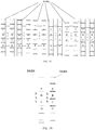
FIG. 1C is a schematic structural diagram illustrating synchronization blocks for a present cell and a neighboring cell used in a method of controlling inter-cell signal interference according to an example. -
FIG. 1D is a first schematic structural diagram illustrating a synchronization block according to an example. -
FIG. 1E is a second schematic structural diagram illustrating a synchronization block according to an example. -
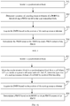
FIG. 2 is a flowchart illustrating another method of controlling inter-cell signal interference according to an example. -
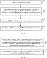
FIG. 3 is a flowchart illustrating a method of controlling inter-cell signal interference according to an example. -
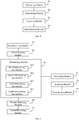
FIG. 4A is a first flowchart illustrating another method of controlling inter-cell signal interference according to an example. -
FIG. 4B is a second flowchart illustrating another method of controlling inter-cell signal interference according to an example. -
FIG. 4C is a flowchart illustrating acquiring configuration information of a cell reference signal according to an example. -
FIG. 5A is a first flowchart illustrating another method of controlling inter-cell signal interference according to an example. -
FIG. 5B is a second flowchart illustrating another method of controlling inter-cell signal interference according to an example. -
FIG. 5C is a flowchart illustrating acquiring configuration information of a cell reference signal according to an example. -
FIG. 6 is a block diagram illustrating an apparatus for controlling inter-cell signal interference according to an example. -
FIG. 7 is a block diagram illustrating another apparatus for controlling inter-cell signal interference according to an example. -
FIG. 8 is a block diagram illustrating an apparatus for controlling inter-cell signal interference according to an example. -
FIG. 9 is a block diagram illustrating another apparatus for controlling inter-cell signal interference according to an example. -
FIG. 10 is a block diagram illustrating an apparatus suitable for controlling inter-cell signal interference according to an example. -
Fig. 11 is a block diagram illustrating an apparatus suitable for controlling inter-cell signal interference according to an example. - Examples will be described in detail herein, with the illustrations thereof represented in the drawings. When the following descriptions involve the drawings, like numerals in different drawings refer to like or similar elements unless otherwise indicated. The embodiments described in the following examples do not represent all embodiments consistent with the present disclosure. Rather, they are merely examples of apparatuses and methods consistent with some aspects of the present disclosure as detailed in the appended claims.
- In an example, referring to
FIG. 1D andFIG. 1E for a structure of a synchronization block, which includes a primary synchronization signal (PSS), a secondary synchronization signal (SSS), a PBCH, and a DMRS interspersed in a frequency domain. In an example, the DMRS may generally be a cyclic shift sequence, which is generated by a ZC (Zadoff-Chu) sequence generation algorithm. -
FIG. 1A is a flowchart illustrating a method of controlling inter-cell signal interference according to an example.FIG. 1B is a scenario diagram illustrating a method of controlling inter-cell signal interference according to an example.FIG. 1C is a schematic structural diagram illustrating synchronization blocks for a present cell and a neighboring cell used in a method of controlling inter-cell signal interference according to an example.FIG. 1D is a first schematic structural diagram illustrating a synchronization block according to an example.FIG. 1E is a second schematic structural diagram illustrating a synchronization block according to an example. The method of controlling inter-cell signal interference can be applied to a base station, and as shown inFIG. 1A , the method of controlling inter-cell signal interference includes the following steps 101-103. - At
step 101, a subcarrier pattern of PBCH symbols for a present cell is generated based on an agreed DMRS configuration mode, every N resource elements in the subcarrier pattern of the PBCH symbols including one resource element for a DMRS and (N-1) resource elements for a PBCH, where N is a natural number greater than 2. - In an example, the agreed DMRS configuration mode may be understood as a DMRS design mode. The DMRS can be designed according to modulo N, where N is a natural number greater than 2. For example, if the DMRS is designed according to modulo 6, it means that the subcarrier pattern of the PBCH symbols includes a DMRS occupying one resource element and a PBCH occupying 5 resource elements. If it is designed according to modulo 4, it means that the subcarrier pattern of the PBCH symbols includes the DMRS occupying one resource element and the PBCH occupying 3 resource elements.
- In an example, the agreed DMRS configuration mode may be understood as a distribution mode of DMRSs across a full bandwidth of the PBCH, in which the DMRSs are evenly interspersed across the full bandwidth of the PBCH, as shown in
FIG. 1D . Or, the DMRSs are interspersed across the bandwidth of the PBCH except a portion coincident with a bandwidth of the secondary synchronization signal in the synchronization block, as shown inFIG. 1E . - In an example, there may be N positions as a starting resource element of the DMRS, and the positions of the starting resource element for neighboring cells can be different, thereby reducing the interference between DMRSs for the neighboring cells. As shown in
FIG. 1C , a DMRS configuration mode with N being 6 is shown. When N is 6, there are 6 positions that can be the position of the starting resource element of the DMRS, for example, the positions of the first, second, third, fourth, fifth, and sixth resource elements from the top may be used as the position of the starting resource element, thus forming 6 kinds of subcarrier patterns, and neighboring cells can use different subcarrier patterns, thereby reducing the interference between DMRSs for neighboring cells. - In an example, the position of the starting resource element of the DMRS for each cell may be agreed on, and the base station does not indicate it to UE through system information. For example, for each macro cell, the system may agree on the position of the starting resource element of the DMRS corresponding to the macro cell. In an example, the position of the starting resource element of the DMRS of each cell may be indicated by the base station to the UE through system information. For example, a position of a starting resource element of a DMRS for a hotspot cell can be indicated by the base station of the macro cell through system information to the hotspot cell base station, or a present cell base station indicates a position of the starting resource element of the DMRS for the neighboring cell to the UE through system information.
- At
step 102, a synchronization block of the present cell is generated based on the subcarrier pattern of the PBCH symbols for the present cell. - In an example, the subcarrier pattern generated at
step 101 may be used to generate a PBCH and a DMRS, which is used for demodulating the PBCH, so that a synchronization block can be generated. - At
step 103, the synchronization block of the present cell is sent directionally by beam sweeping. - In an example, the base station may send the synchronization block in each direction by beam sweeping on a transmission window agreed on in a system.
- In an example, the base station may preset a transmission window corresponding to the synchronization block of the present cell to be different from a transmission window corresponding to a synchronization block of a neighboring cell; and/or, preset a position of the starting resource element of the DMRS in the synchronization block of the present cell to be different from a position of a starting resource element of a DMRS carried in the synchronization block of the neighboring cell. That is, it ensured that the DMRSs for the cells cannot be the same in both of the time domain and the frequency domain, to further avoid the interference problem between DMRSs for the present cell and the neighboring cell.
- In an exemplary scenario, as shown in
FIG. 1B , the scenario shown inFIG. 1B includesbase station 11,base station 12, ...,base station 1N, and UE (such as a smartphone, a tablet, etc.) 20.Base station 11,base station 12, ..., and base station IN can be understood as base stations of neighboring cells.UE 20 can monitor synchronization blocks sent bybase station 11,base station 12, ..., andbase station 1N. In order to avoid interference generated among DMRSs in the synchronization blocks sent bybase station 11,base station 12, ..., andbase station 1N, unique configuration modes can be designed for the DMRSs to ensure that the transmission windows corresponding to the synchronization blocks broadcast by different base stations are different and/or the positions of the starting resource elements of the DMRSs carried in the synchronization blocks are different. - In this example, through the
above steps 101 to 103, the base station can generate the subcarrier pattern of the PBCH symbols for the present cell based on the agreed DMRS configuration mode, and then generate the synchronization block of the present cell, which is sent directionally by beam sweeping. By generating the subcarrier pattern for the present cell based on the agreed DMRS configuration mode, the density of the DMRS in the subcarrier pattern can be reduced, thereby solving the interference problem caused by increased power due to improper configuration of cell reference signals in the synchronization block, and avoiding signal interference between neighboring cells. - In an example, the method of controlling inter-cell signal interference may further include:
- setting a transmission window corresponding to the synchronization block of the present cell to be different from a transmission window corresponding to a synchronization block of a neighboring cell; and/or
- setting a position of a starting resource element of a DMRS in the synchronization block of the present cell to be different from a position of a starting resource element of the DMRS carried in the synchronization block of the neighboring cell.
- In an example, the method of controlling inter-cell signal interference may further include:
- sending system information carrying configuration information of a cell reference signal for a neighboring cell to User Equipment (UE), where the configuration information includes a position of a starting resource element of a DMRS in a synchronization block of the neighboring cell.
- In an example, the agreed DMRS configuration mode includes:
- the DMRSs being evenly interspersed across a full bandwidth of the PBCH; or
- the DMRSs being interspersed across the bandwidth of the PBCH except a portion coincident with a bandwidth of a secondary synchronization signal in the synchronization block.
- For details about how to control the inter-cell signal interference, reference can be made to the subsequent examples.
- The following describes the technical solutions provided by the examples of the present disclosure with specific examples.
-
FIG. 2 is a flowchart illustrating another method of controlling inter-cell signal interference according to an example. This example takes, with the above-mentioned method provided in the example of the present disclosure, interaction between a base station and UE to implement controlling the inter-cell measurement signal interference as an example for illustrative description. As shown inFIG. 2 , the method includes the following steps. - At step 201, the base station generates a subcarrier pattern of PBCH symbols for a present cell based on an agreed DMRS configuration mode.
- In an example, every N resource elements in the subcarrier pattern of the PBCH symbols includes one resource element for a DMRS and (N-1) resource elements for a PBCH, where N is a natural number greater than 2.
- At
step 202, the base station generates a synchronization block of the present cell based on the subcarrier pattern of the PBCH symbols for the present cell. - At
step 203, the base station sends the synchronization block, and step 205 is performed. - In an example, a transmission window corresponding to the synchronization block of the present cell is different from a transmission window corresponding to a synchronization block of a neighboring cell, and/or a position of a starting resource element of a DMRS carried in the synchronization block of the present cell is different from a position of a starting resource element of a DMRS carried in the synchronization block of the neighboring cell.
- In an example, for the details of
steps 201 and 202, reference may be made to the descriptions ofsteps FIG. 1A , which will not be described here. - At step 204, the base station sends the UE system information carrying configuration information of a cell reference signal for a neighboring cell, and the configuration information of the cell reference signal for the neighboring cell includes a position of a starting resource element of a DMRS carried in a synchronization block of the neighboring cell, and step 206 is performed.
- In an example, the base station of the present cell to which the UE accesses may send the UE the system information carrying the configuration information of the cell reference signal for the neighboring cell, so that when receiving the synchronization block from the neighboring cell, the UE can determine the position of the DMRS in the synchronization block based on the corresponding configuration information of the cell reference signal, so as to demodulate the PBCH symbols.
- In an example, the configuration information of the cell reference signal can be understood as the subcarrier pattern of the PBCH symbols for the neighboring cell, such as the position of the starting resource element of the DMRS and the density of the DMRS. The density of the DMRS can be understood as a ratio of the number of resource elements occupied by the DMRS against that occupied by the PBCH in the PBCH symbols.
- At
step 205, the UE monitors the synchronization block. - At
step 206, the UE determines the position of the starting resource element of the DMRS for demodulating the PBCH carried in the synchronization block. - In an example, when the UE does not obtain the position of the starting resource element of the DMRS in advance, the UE may determine the position of the starting resource element of the DMRS through a blind decoding manner. For example, if the DMRS configuration mode is designed according to modulo 6, and the position of the starting resource element can be determined through no more than 6 times of blind decoding.
- In an example, the position of the starting resource element of the DMRS may be determined based on system agreement. For example, for a macro cell, the position of the starting resource element of the DMRS may be determined based on the system agreement, such as the position of the starting resource element of the DMRS corresponding to the macro cell is the first resource element.
- In an example, the position of the starting resource element of the DMRS may be determined based on the configuration information of the cell reference signal configured in the system information. For example, for a hotspot cell or a neighboring cell, the position of the starting resource element of the DMRS for the hotspot cell or the neighboring cell may be determined based on the configuration information of the cell reference signal in the system information from the present cell.
- In an example, a procedure for the UE to determine the position of the starting resource element of the DMRS carried in the synchronization block for demodulating the PBCH can be referred to the descriptions shown in
FIG. 4A ,FIG. 4B ,FIG. 5A, and FIG. 5B , and will not be described in detail here. - At
step 207, the UE acquires the DMRS based on the position of the starting resource element. - At
step 208, the UE demodulates the PBCH based on the DMRS to obtain PBCH content of the PBCH. - In an example, a sequence of blind decoding may be performed on the acquired DMRS, and then the DMRS is determined, and then the PBCH is demodulated to obtain PBCH content of the PBCH.
- In this example, through the above steps 201 to 208, the base station can generate the subcarrier pattern of the PBCH symbols for the present cell based on the agreed DMRS configuration mode, and send the synchronization block carrying the PBCH of the present cell and the DMRS for demodulating the PBCH in the transmission window of the synchronization block corresponding to the present cell. Upon monitoring the synchronization block, the UE may first determine the position of the starting resource element of the DMRS, and then can successfully demodulate the PBCH. Therefore, by configuring the DMRS, the time domain resource and the frequency domain resource conflict between the cell reference signals in the synchronization blocks for the present cell and the neighboring cell may be avoid, and the interference problem caused by increased power due to improper configuration of cell reference signals in the 5G system may be solved.
-
FIG. 3 is a flowchart illustrating a method of controlling inter-cell signal interference according to an example. The method of controlling inter-cell signal interference may be applied to UE. As shown inFIG. 3 , the method of controlling inter-cell signal interference includes the following steps 301-304. - At
step 301, a synchronization block is monitored. - At
step 302, a position of a starting resource element of a DMRS is determined, which is carried in the synchronization block and used for demodulating a PBCH. - In an example, the position of the starting resource element of the DMRS in the synchronization block can be determined based on two manners.
- Manner 1. When the UE does not determine in advance the position of the starting resource element of the DMRS in the synchronization block of any cell, reference can be made to the examples shown in
FIG. 4A andFIG. 4B to determine the position of the starting resource element of the DMCH signal for demodulating the PBCH carried in the synchronization block, which will not be described here. -
Manner 2. When a system previously agrees on a position of the starting resource element of the DMRS for each macro cell, and while a position of the starting resource element of the DMRS for the hotspot cell is not previously agreed on in the system, reference can be made to the examples shown inFIG. 5A and FIG. 5B to determine the position of the starting resource element of the DMRS for demodulating the PBCH carried in the synchronization block, which will not be described here. - At
step 303, the DMRS is acquired based on the position of the starting resource element. - At
step 304, the PBCH is demodulated based on the DMRS to obtain PBCH content of the PBCH. - In an exemplary scenario, as shown in
FIG. 1B , the scenario shown inFIG. 1B includesbase station 11,base station 12, ...,base station 1N, and UE (such as a smartphone, a tablet, etc.) 20.Base station 11,base station 12, ..., and base station IN can be understood as base stations of neighboring cells.UE 20 can monitor synchronization blocks sent bybase station 11,base station 12, ..., andbase station 1N. In order to avoid interference generated among DMRSs in the synchronization blocks sent bybase station 11,base station 12, ..., andbase station 1N, unique configuration modes can be designed for the DMRSs to ensure that the transmission windows corresponding to the synchronization blocks broadcast by different base stations are different and/or the positions of the starting resource elements of the DMRSs carried in the synchronization blocks are different. Upon monitoring a synchronization block,UE 20 can first determine the cell to which the synchronization block belongs, and then determine a position of a starting resource element of a corresponding DMRS, thereby avoiding the time domain resource and the frequency domain resource conflict between cell reference signals in the synchronization blocks for a present cell and a neighboring cell, and solving the interference problem caused by increased power due to improper configuration of cell reference signals in the 5G system. - In this example, through the
above steps 301 to 304, upon monitoring the synchronization block, the UE can first determine the position of the starting resource element of the DMRS, and then can obtain the PBCH through analyzing. Therefore, by configuring different subcarrier patterns of PBCH symbols for neighboring cells, it can avoid the time domain resource and the frequency domain resource conflict between the cell reference signals in the synchronization blocks for the present cell and the neighboring cell, and solve t the interference problem caused by increased power due to improper configuration of cell reference signals in the 5G system. - In an example, determining the position of the starting resource element of the DMRS for demodulating the PBCH carried in the synchronization block includes:
when the synchronization block is a synchronization block from a cell where the UE is to reside or a present cell associated with the UE, determining the position of the starting resource element of the DMRS by position blind decoding. - In an example, determining the position of the starting resource element of the DMRS for demodulating the PBCH carried in the synchronization block includes:
when the synchronization block is a synchronization block from a neighboring cell of the present cell where the UE resides, determining the position of the starting resource element of the DMRS based on configuration information of a cell reference signal for the neighboring cell. - In an example, the method of controlling inter-cell signal interference may further include:
- receiving system information sent by a base station and carrying the configuration information of the cell reference signal for the neighboring cell, where the configuration information of the cell reference signal for the neighboring cell includes a position of a starting resource element of a DMRS carried in the synchronization block of the neighboring cell; and
- analyzing the system information to obtain the configuration information of the cell reference signal for the neighboring cell.
- In an example, determining the position of the starting resource element of the DMRS for demodulating the PBCH carried in the synchronization block includes:
when the synchronization block is a synchronization block from a macro cell, determining the position of the starting resource element of the DMRS based on a system agreement. - In an example, determining the position of the starting resource element of the DMRS for demodulating the PBCH carried in the synchronization block includes:
when the synchronization block is a synchronization block from a hotspot cell, determining the position of the starting resource element of the DMRS based on configuration information of a cell reference signal for the hotspot cell. - In an example, the method of controlling inter-cell signal interference may further include:
- receiving system information sent by a base station of the macro cell and carrying the configuration information of the cell reference signal for the hotspot cell, where the configuration information of the cell reference signal for the hotspot cell includes a position of a starting resource element of a DMRS carried in the synchronization block of the hotspot cell; and
- analyzing the system information to obtain the configuration information of the cell reference signal for the hotspot cell.
- For details about the inter-cell signal interference control, reference can be made to the subsequent examples.
- The following describes the technical solutions provided by the examples of the present disclosure with specific examples.
-
FIG. 4A is a first flowchart of another method of controlling inter-cell signal interference according to an example.FIG. 4B is a second flowchart of another method of controlling inter-cell signal interference according to an example.FIG. 4C is a flowchart of acquiring configuration information of a cell reference signal according to an example. This example takes, with the above method provided by the example of the present disclosure, determining a position of a starting resource element of a DMRS when the UE does not determine in advance the position of the starting resource element of the DMRS in the synchronization block of any cell as an example for illustrative description. As shown inFIG. 4A , when the synchronization block is a synchronization block from a cell where the UE is to reside or a synchronization block from a present cell where the UE resides, a procedure of determining the position of the starting resource element of the DMRS includes following steps. - At
step 401, a synchronization block is monitored. - At
step 402, when the synchronization block is a synchronization block from a cell where the UE is to reside or a synchronization block from a present cell where the UE resides, a position of a starting resource element of a DMRS is determined by position blind decoding. - In an example, when the UE is not currently resided in any cell, and a cell to be resided is selected by monitoring a synchronization block, since the UE is not sure about a position of a starting resource element of a DMRS for the cell to be resided, the position of the starting resource element of the DMRS can be determined by performing position blind decoding for the DMRS in the synchronization block.
- In an example, when the UE has resided in a certain cell, if the UE monitors a synchronization block from the present cell in which the UE resides, a position of a starting resource element of a DMRS in a synchronization block may be determined by performing position blind decoding for the DMRS in the synchronization block.
- At
step 403, the DMRS is acquired based on the position of the starting resource element. - At
step 404, a PBCH is demodulated based on the DMRS to obtain PBCH content of the PBCH. - As shown in
FIG. 4B , when the synchronization block is a synchronization block from a cell neighboring with the present cell where the UE resides, a procedure of determining a position of a starting resource element of a DMRS includes following steps. - At
step 411, a synchronization block is monitored. - At
step 412, when the synchronization block is a synchronization block from a cell neighboring with the present cell where the UE resides, a position of a starting resource element of a DMRS is determined based on configuration information of a cell reference signal for the neighboring cell. - In an example, when UE residing in the present cell monitors a synchronization block from a neighboring cell, the UE may determine the position of the starting resource element of the DMRS based on the configuration information of the cell reference signal for the neighboring cell.
- In an example, the configuration information of the cell reference signal for the neighboring cell may be obtained as shown in the example in
FIG. 4C . As shown inFIG. 4C , the obtaining includes the following steps. - At
step 421, system information sent by a base station and carrying configuration information of a cell reference signal for a neighboring cell is received, and the configuration information of the cell reference signal for the neighboring cell includes a position of a starting resource element of a DMRS carried in the synchronization block of the neighboring cell. - In an example, an information unit can be defined in the system information to configure configuration information of a cell reference signal for a neighboring cell. For example, if there are 6 positions of the starting resource element of the DMRS, the position of the starting resource element of the DMRS for each cell may be indicated by a 3-bit information unit.
- At
step 422, the system information is analyzed to obtain the configuration information of the cell reference signal for the neighboring cell. - At
step 413, the DMRS is acquired based on the position of the starting resource element. - At
step 414, a PBCH is demodulated based on the DMRS to obtain PBCH content of the PBCH. - In this example, upon monitoring a synchronization block, the UE may determine the position of the starting resource element of the DMRS in the synchronization block from the present cell or the cell to be resided through blind decoding, or determine the position of the starting resource element of the DMRS for the neighboring cell from configuration information of the cell reference signal. Then, a PBCH is demodulated to obtain PBCH content. By configuring different subcarrier patterns of PBCH symbols for neighboring cells respectively, it can avoid the time domain resource and the frequency domain resource conflict between cell reference signals in the synchronization blocks for the present cell and the neighboring cell, and solve the interference problem caused by increased power due to improper configuration of cell reference signals in the 5G system.
-
FIG. 5A is a first flowchart illustrating another method of controlling inter-cell signal interference according to an example.FIG. 5B is a second flowchart illustrating another method of controlling inter-cell signal interference according to an example.FIG. 5C is a flowchart illustrating acquiring configuration information of a cell reference signal according to an example. This example takes, with the above method provided by the example of the present disclosure, determining a position of a starting resource element of a DMRS when a system previously agrees on the position of the starting resource element of the DMRS for each macro cell, while a position of the starting resource element of the DMRS for the hotspot cell is not previously agreed on in the system as an example for illustrative description. As shown inFIG. 5A , when the synchronization block is a synchronization block from a cell where the UE is to reside or a present cell of the UE, a procedure of determining the position of the starting resource element of the DMRS includes following steps. - At
step 501, a synchronization block is monitored. - At
step 502, when the synchronization block is a synchronization block from a macro cell, a position of a starting resource element of a DMRS is determined based on system agreement. - At
step 503, the DMRS is acquired based on the position of the starting resource element. - At
step 504, a PBCH is demodulated based on the DMRS to obtain PBCH content of the PBCH. - As shown in
FIG. 5B , when the synchronization block is a synchronization block from a hotspot cell, a procedure of determining a position of a starting resource element of a DMRS includes following steps. - At
step 511, a synchronization block is monitored. - At
step 512, when the synchronization block is a synchronization block from a hotspot cell, a position of a starting resource element of a DMRS is determined based on configuration information of a cell reference signal for the hotspot cell. - In an example, since the UE generally does not know the configuration of the hotspot cell by default, the base station of the macro cell generally is to perform configuration for each hotspot cell within its coverage area in the system information, so that the UE monitors and searches for the hotspot cell and resides in the hotspot cell.
- In an example, the base station of the macro cell may configure the configuration information of the cell reference signal for the hotspot cell in the system information.
- In an example, the configuration information of the cell reference signal for the hotspot cell may be obtained as shown in the example in
FIG. 5C . As shown inFIG. 5C , the obtaining includes the following steps. - At
step 521, system information sent by a base station of a macro cell and carrying configuration information of the cell reference signal for a hotspot cell is received, and the configuration information of the cell reference signal for the hotspot cell includes a position of a starting resource element of a DMRS carried in the synchronization block of the hotspot cell. - In an example, when a user resides in a hotspot cell, system information may also be used to indicate to the UE configuration information of a cell reference signal for a neighboring hotspot cell.
- At
step 522, the system information is analyzed to obtain the configuration information of the cell reference signal for the hotspot cell. - At
step 513, the DMRS is acquired based on the position of the starting resource element. - At
step 514, a PBCH is demodulated based on the DMRS to obtain PBCH content of the PBCH. - In this example, upon monitoring a synchronization block from a macro cell, the UE may determine the position of the starting resource element of the DMRS in the synchronization block from the macro cell based on the system agreement. Upon monitoring a synchronization block from a hotspot cell, the UE may determine the position of the starting resource element of the DMRS for the hotspot cell through the configuration information of the cell reference signal. Since the UE does not determine the position of the starting resource element of the DMRS through blind decoding, a calculation amount by the UE can be reduced. By configuring different subcarrier patterns of PBCH symbols for neighboring cells respectively, it can avoid the time domain resource and the frequency domain resource conflict between cell reference signals in the synchronization blocks for the present cell and the neighboring cell, and solve the interference problem caused by increased power due to improper configuration of cell reference signals in the 5G system.
-
FIG. 6 is a block diagram illustrating an apparatus for controlling inter-cell signal interference according to an example, and the apparatus is applied to a base station. As shown inFIG. 6 , the apparatus for controlling inter-cell signal interference includes: - a
first generating module 61 configured to generate a subcarrier pattern of PBCH symbols for a present cell based on an agreed DMRS configuration mode, every N resource elements in the subcarrier pattern of the PBCH symbols including one resource element for a DMRS and (N-1) resource elements for a PBCH, where N is a natural number greater than 2; - a
second generating module 62 configured to generate a synchronization block of the present cell based on the subcarrier pattern of the PBCH symbols for the present cell, generated by thefirst generating module 61; and - a
first sending module 63 configured to send the synchronization block of the present cell, generated by thesecond generating module 62, directionally by beam sweeping. - A transmission window corresponding to the synchronization block of the present cell and/or a position of a starting resource element of a DMRS carried in the synchronization block of the present cell is different from a transmission window corresponding to a synchronization block of a neighboring cell and/or a position of a starting resource element of the DMRS carried in the synchronization block of the neighboring cell.
-
FIG. 7 is a block diagram illustrating another apparatus for controlling inter-cell signal interference according to an example. As shown inFIG. 7 , based on the example ofFIG. 6 , in an example, the apparatus also includes: - a
setting module 64 configured to set a transmission window corresponding to the synchronization block of the present cell to be different from a transmission window corresponding to a synchronization block of a neighboring cell, and/or set a position of a starting resource element of a DMRS in the synchronization block of the present cell to be different from a position of a starting resource element of the DMRS carried in the synchronization block of the neighboring cell. - In an example, the apparatus also includes:
- a
second sending module 65 configured to send system information carrying configuration information of a cell reference signal for a neighboring cell to UE, where the configuration information includes a position of a starting resource element of a DMRS in a synchronization block of the neighboring cell. - In an example, the agreed DMRS configuration mode includes:
- the DMRSs being evenly interspersed across a full bandwidth of the PBCH; or
- the DMRSs being interspersed across the bandwidth of the PBCH except a portion coincident with a bandwidth of a secondary synchronization signal in the synchronization block.
-
FIG. 8 is a block diagram illustrating an apparatus for controlling inter-cell signal interference according to an example, and the apparatus is applied to UE. As shown inFIG. 6 , the apparatus for controlling inter-cell signal interference includes: - a
monitoring module 81 configured to monitor a synchronization block; - a determining
module 82 configured to determine a position of a starting resource element of a DMRS for demodulating a PBCH carried in the synchronization block, which is monitored by themonitoring module 81; - an acquiring
module 83 configured to acquire the DMRS based on the position of the starting resource element, which is determined by the determiningmodule 82; and - a
demodulating module 84 configured to demodulate the PBCH based on the DMRS, which is acquired by the acquiringmodule 83, to obtain PBCH content of the PBCH. -
FIG. 9 is a block diagram illustrating another apparatus for controlling inter-cell signal interference according to an example. As shown inFIG. 9 , based on the example ofFIG. 8 , in an example, the determiningmodule 82 includes:
a first determining sub-module 821 configured to, when the synchronization block is a synchronization block from a cell where the UE is to reside or a present cell associated with the UE, determine the position of the starting resource element of the DMRS by position blind decoding. - In an example, the determining
module 82 includes:
a second determining sub-module 822 configured to, when the synchronization block is a synchronization block from a neighboring cell of the present cell where the UE resides, determine the position of the starting resource element of the DMRS based on configuration information of a cell reference signal for the neighboring cell. - In an example, the apparatus also includes:
- a
first receiving module 85 configured to receive system information sent by a base station and carrying the configuration information of the cell reference signal for the neighboring cell, where the configuration information of the cell reference signal for the neighboring cell includes a position of a starting resource element of a DMRS carried in the synchronization block of the neighboring cell; and - a
first analyzing module 86 configured to analyze the system information, received by thefirst receiving module 85, to obtain the configuration information of the cell reference signal for the neighboring cell. - In an example, the determining
module 82 includes:
a third determining sub-module 823 configured to, when the synchronization block is a synchronization block from a macro cell, determine the position of the starting resource element of the DMRS based on a system agreement. - In an example, the determining
module 82 includes:
a fourth determining sub-module 824 configured to, when the synchronization block is a synchronization block from a hotspot cell, determine the position of the starting resource element of the DMRS based on configuration information of a cell reference signal for the hotspot cell. - In an example, the apparatus also includes:
- a
second receiving module 87 configured to receive system information sent by a base station of the macro cell and carrying the configuration information of the cell reference signal for the hotspot cell, where the configuration information of the cell reference signal for the hotspot cell includes a position of a starting resource element of a DMRS carried in the synchronization block of the hotspot cell; and - a
second analyzing module 88 configured to analyze the system information, received by thesecond receiving module 87, to obtain the configuration information of the cell reference signal for the hotspot cell. - Regarding the apparatuses in the above examples, the specific manner in which each module performs operations has been described in detail in the examples of the methods, and will not be described in detail here.
-
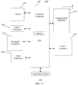
FIG. 10 is a block diagram illustrating an apparatus suitable for controlling inter-cell signal interference according to an example. Anapparatus 1000 may be provided as a base station. Referring toFIG. 10 , theapparatus 1000 includes aprocessing component 1022, a wireless transmitting /receiving component 1024, anantenna component 1026, and a signal processing portion dedicated to a wireless interface. Theprocessing component 1022 may further include one or more processors. - One of the processors in the
processing component 1022 may be configured to perform the above method for controlling inter-cell signal interference. - In an example, there is also provided a non-transitory computer-readable storage medium including instructions, which may be executed by the
processing component 1022 of theapparatus 1000 to complete the method described in the first aspect above. For example, the non-transitory computer-readable storage medium may be a ROM, a random access memory (RAM), a CD-ROM, a magnetic tape, a floppy disk, an optical data storage device, and the like. -
FIG. 11 is a block diagram illustrating an apparatus suitable for controlling inter-cell signal interference according to an example. For example, anapparatus 1100 may be UE, for example, a smart phone. - Referring to
FIG. 11 , theapparatus 1100 may include one or more of the following components: aprocessing component 1102, amemory 1104, apower component 1106, amultimedia component 1108, anaudio component 1110, an input/output (I/O)interface 1112, asensor component 1114, and acommunication component 1116. - The
processing component 1102 typically controls overall operations of theapparatus 1100, such as the operations associated with display, phone call, data communications, camera operations, and recording operations. Theprocessing component 1102 may include one ormore processors 1120 to execute instructions, to perform all or part of the steps of the above method. Moreover, theprocessing component 1102 may include one or more modules which facilitate the interaction between theprocessing component 1102 and other components. For instance, theprocessing component 1102 may include a multimedia module to facilitate the interaction between themultimedia component 1108 and theprocessing component 1102. - The
memory 1104 is configured to store various types of data to support the operation of theapparatus 1100. Examples of such data include instructions for any applications or methods operated on theapparatus 1100, messages, pictures, etc. Thememory 1104 may be implemented using any type of volatile or non-volatile memory devices, or a combination thereof, such as a static random access memory (SRAM), an electrically erasable programmable read-only memory (EEPROM), an erasable programmable read-only memory (EPROM), a programmable read-only memory (PROM), a read-only memory (ROM), a magnetic memory, a flash memory, a magnetic or optical disk. - The
power component 1106 provides power to various components of theapparatus 1100. Thepower component 1106 may include a power management system, one or more power sources, and any other components associated with the generation, management, and distribution of power in theapparatus 1100. - The
multimedia component 1108 includes a screen providing an output interface between theapparatus 1100 and the user. In some embodiments, the screen may include a liquid crystal display (LCD) and a touch panel (TP). If the screen includes the touch panel, the screen may be implemented as a touch screen to receive input signals from the user. The touch panel includes one or more touch sensors to sense touches, swipes, and gestures on the touch panel. The touch sensors may not only sense a boundary of a touch or swipe action, but also sense a period of time and a pressure associated with the touch or swipe action. In some embodiments, themultimedia component 1108 includes a front camera and/or a rear camera. When theapparatus 1100 is in an operation mode, such as a shooting mode or a video mode, the front camera and/or the rear camera can receive external multimedia data. Each front and rear camera can be a fixed optical lens system or have focal length and optical zoom capability. - The
audio component 1110 is configured to output and/or input audio signals. For example, theaudio component 1110 includes a microphone (MIC) configured to receive an external audio signal when theapparatus 1100 is in an operation mode, such as a call mode, a recording mode, and a voice recognition mode. The received audio signal may be further stored in thememory 1104 or transmitted via thecommunication component 1116. In some examples, theaudio component 1110 further includes a speaker to output audio signals. - The I/
O interface 1112 provides an interface between theprocessing component 1102 and peripheral interface modules, such as a keyboard, a click wheel, buttons, and the like. These buttons may include, but are not limited to, a home button, a volume button, a start button, and a lock button. - The
sensor component 1114 includes one or more sensors to provide status assessments of various aspects of theapparatus 1100. For instance, thesensor component 1114 may detect an on/off status of theapparatus 1100, relative positioning of components, e.g., the display and the keypad, of theapparatus 1100, a change in position of theapparatus 1100 or a component of theapparatus 1100, a presence or absence of user contact with theapparatus 1100, an orientation or an acceleration/deceleration of theapparatus 1100, and a change in temperature of theapparatus 1100. Thesensor component 1114 may include an optical sensor, such as a Complementary Metal-Oxide-Semiconductor (CMOS) or Charged Coupled Device (CCD) image sensor which is used in imaging applications. In some embodiments, thesensor component 1114 may also include an accelerometer sensor, a gyroscope sensor, a magnetic sensor, a pressure sensor, or a temperature sensor. - The
communication component 1116 is configured to facilitate communication, wired or wirelessly, between theapparatus 1100 and other devices. Theapparatus 1100 can access a wireless network based on a communication standard, such as Wi-Fi, 2G, or 3G, or a combination thereof. In one exemplary embodiment, thecommunication component 1116 receives a broadcast signal or broadcast associated information from an external broadcast management system via a broadcast channel. In one exemplary embodiment, thecommunication component 1116 further includes a near field communication (NFC) module to facilitate short-range communications. For example, the NFC module may be implemented based on a radio frequency identification (RFID) technology, an infrared data association (IrDA) technology, an ultra-wideband (UWB) technology, a Bluetooth (BT) technology, and other technologies. - In exemplary embodiments, the
apparatus 1100 may be implemented with one or more application specific integrated circuits (ASICs), digital signal processors (DSPs), digital signal processing devices (DSPDs), programmable logic devices (PLDs), field programmable gate arrays (FPGAs), controllers, micro-controllers, microprocessors, or other electronic components, to perform the above method of controlling inter-cell signal interference described in the second aspect. - In exemplary embodiments, there is also provided a non-transitory computer-readable storage medium including instructions, such as included in the
memory 1104, executable by theprocessor 1120 in theapparatus 1100 to perform the above method described in the second aspect. For example, the non-transitory computer-readable storage medium may be a ROM, a RAM, a CD-ROM, a magnetic tape, a floppy disc, an optical data storage device, and the like. - Other embodiments of the disclosure will be apparent to those skilled in the art from consideration of the specification and practice of the disclosure disclosed here. This application is intended to cover any variations, uses, or adaptations of the disclosure following the general principles thereof and including such departures from the present disclosure as come within known or customary practice in the art. It is intended that the specification and examples be considered as exemplary only, with a true scope and spirit of the disclosure being indicated by the following claims.
- It will be appreciated that the present disclosure is not limited to the exact construction that has been described above and illustrated in the accompanying drawings, and that various modifications and changes may be made without departing from the scope thereof. It is intended that the scope of the disclosure only be limited by the appended claims.
Claims (26)
- A method of controlling inter-cell signal interference, the method being applied to a base station and comprising:generating a subcarrier pattern of Physical Broadcast Channel (PBCH) symbols for a present cell based on an agreed Demodulation Reference Signal (DMRS) configuration mode, every N resource elements in the subcarrier pattern of the PBCH symbols comprising one resource element for a DMRS and (N-1) resource elements for a PBCH, wherein N is a natural number greater than 2;generating a synchronization block of the present cell based on the subcarrier pattern of the PBCH symbols for the present cell; andsending the synchronization block of the present cell directionally by beam sweeping.
- The method according to claim 1, further comprising:setting a transmission window corresponding to the synchronization block of the present cell to be different from a transmission window corresponding to a synchronization block of a neighboring cell; and/orsetting a position of a starting resource element of a DMRS in the synchronization block of the present cell to be different from a position of a starting resource element of the DMRS carried in the synchronization block of the neighboring cell.
- The method according to claim 1, further comprising:
sending system information carrying configuration information of a cell reference signal for a neighboring cell to User Equipment (UE), wherein the configuration information comprises a position of a starting resource element of a DMRS in a synchronization block of the neighboring cell. - The method according to claim 1, wherein the agreed DMRS configuration mode comprises:the DMRSs being evenly interspersed across a full bandwidth of the PBCH; orthe DMRSs being interspersed across the bandwidth of the PBCH except a portion coincident with a bandwidth of a secondary synchronization signal in the synchronization block.
- A method of controlling inter-cell signal interference, the method being applied to UE and comprising:monitoring a synchronization block;determining a position of a starting resource element of a DMRS for demodulating a PBCH carried in the synchronization block;acquiring the DMRS based on the position of the starting resource element; anddemodulating the PBCH based on the DMRS to obtain PBCH content of the PBCH.
- The method according to claim 5, wherein determining the position of the starting resource element of the DMRS for demodulating the PBCH carried in the synchronization block comprises:
when the synchronization block is a synchronization block from a cell where the UE is to reside or a present cell associated with the UE, determining the position of the starting resource element of the DMRS by position blind decoding. - The method according to claim 5, wherein determining the position of the starting resource element of the DMRS for demodulating the PBCH carried in the synchronization block comprises:
when the synchronization block is a synchronization block from a neighboring cell of the present cell where the UE resides, determining the position of the starting resource element of the DMRS based on configuration information of a cell reference signal for the neighboring cell. - The method according to claim 7, further comprising:receiving system information sent by a base station and carrying the configuration information of the cell reference signal for the neighboring cell, wherein the configuration information of the cell reference signal for the neighboring cell comprises a position of a starting resource element of a DMRS carried in the synchronization block of the neighboring cell; andanalyzing the system information to obtain the configuration information of the cell reference signal for the neighboring cell.
- The method according to claim 5, wherein determining the position of the starting resource element of the DMRS for demodulating the PBCH carried in the synchronization block comprises:
when the synchronization block is a synchronization block from a macro cell, determining the position of the starting resource element of the DMRS based on a system agreement. - The method according to claim 9, wherein determining the position of the starting resource element of the DMRS for demodulating the PBCH carried in the synchronization block comprises:
when the synchronization block is a synchronization block from a hotspot cell, determining the position of the starting resource element of the DMRS based on configuration information of a cell reference signal for the hotspot cell. - The method according to claim 10, further comprising:receiving system information sent by a base station of the macro cell and carrying the configuration information of the cell reference signal for the hotspot cell, wherein the configuration information of the cell reference signal for the hotspot cell comprises a position of a starting resource element of a DMRS carried in the synchronization block of the hotspot cell; andanalyzing the system information to obtain the configuration information of the cell reference signal for the hotspot cell.
- An apparatus for controlling inter-cell signal interference, comprising:a first generating module configured to generate a subcarrier pattern of PBCH symbols for a present cell based on an agreed DMRS configuration mode, every N resource elements in the subcarrier pattern of the PBCH symbols comprising one resource element for a DMRS and (N-1) resource elements for a PBCH, wherein N is a natural number greater than 2;a second generating module configured to generate a synchronization block of the present cell based on the subcarrier pattern of the PBCH symbols for the present cell, generated by the first generating module; anda first sending module configured to send the synchronization block of the present cell, generated by the second generating module, directionally by beam sweeping.
- The apparatus according to claim 12, further comprising:
a setting module configured to set a transmission window corresponding to the synchronization block of the present cell to be different from a transmission window corresponding to a synchronization block of a neighboring cell, and/or set a position of a starting resource element of a DMRS in the synchronization block of the present cell to be different from a position of a starting resource element of the DMRS carried in the synchronization block of the neighboring cell. - The apparatus according to claim 12, further comprising:
a second sending module configured to send system information carrying configuration information of a cell reference signal for a neighboring cell to UE, wherein the configuration information comprises a position of a starting resource element of a DMRS in a synchronization block of the neighboring cell. - The apparatus according to claim 12, wherein the agreed DMRS configuration mode comprises:the DMRSs being evenly interspersed across a full bandwidth of the PBCH; orthe DMRSs being interspersed across the bandwidth of the PBCH except a portion coincident with a bandwidth of a secondary synchronization signal in the synchronization block.
- An apparatus for controlling inter-cell signal interference, the apparatus being applied to UE and comprising:a monitoring module configured to monitor a synchronization block;a determining module configured to determine a position of a starting resource element of a DMRS for demodulating a PBCH carried in the synchronization block, which is monitored by the monitoring module;an acquiring module configured to acquire the DMRS based on the position of the starting resource element, which is determined by the determining module; anda demodulating module configured to demodulate the PBCH based on the DMRS, which is acquired by the acquiring module, to obtain PBCH content of the PBCH.
- The apparatus according to claim 16, wherein the determining module comprises:
a first determining sub-module configured to, when the synchronization block is a synchronization block from a cell where the UE is to reside or a present cell associated with the UE, determine the position of the starting resource element of the DMRS by position blind decoding. - The apparatus according to claim 16, wherein the determining module comprises:
a second determining sub-module configured to, when the synchronization block is a synchronization block from a neighboring cell of the present cell where the UE resides, determine the position of the starting resource element of the DMRS based on configuration information of a cell reference signal for the neighboring cell. - The apparatus according to claim 18, further comprising:a first receiving module configured to receive system information sent by a base station and carrying the configuration information of the cell reference signal for the neighboring cell, wherein the configuration information of the cell reference signal for the neighboring cell comprises a position of a starting resource element of a DMRS carried in the synchronization block of the neighboring cell; anda first analyzing module configured to analyze the system information, received by the first receiving module, to obtain the configuration information of the cell reference signal for the neighboring cell.
- The apparatus according to claim 16, wherein the determining module comprises:
a third determining sub-module configured to, when the synchronization block is a synchronization block from a macro cell, determine the position of the starting resource element of the DMRS based on a system agreement. - The apparatus according to claim 20, wherein the determining module comprises:
a fourth determining sub-module configured to, when the synchronization block is a synchronization block from a hotspot cell, determine the position of the starting resource element of the DMRS based on configuration information of a cell reference signal for the hotspot cell. - The apparatus according to claim 21, further comprising:a second receiving module configured to receive system information sent by a base station of the macro cell and carrying the configuration information of the cell reference signal for the hotspot cell, wherein the configuration information of the cell reference signal for the hotspot cell comprises a position of a starting resource element of a DMRS carried in the synchronization block of the hotspot cell; anda second analyzing module configured to analyze the system information, received by the second receiving module, to obtain the configuration information of the cell reference signal for the hotspot cell.
- Abase station, comprising:a processor; anda memory for storing instructions executable by the processor,wherein the processor is configured to:generate a subcarrier pattern of PBCH symbols for a present cell based on an agreed DMRS configuration mode, every N resource elements in the subcarrier pattern of the PBCH symbols comprising one resource element for a DMRS and (N-1) resource elements for a PBCH, wherein N is a natural number greater than 2;generate a synchronization block of the present cell based on the subcarrier pattern of the PBCH symbols for the present cell; andsend the synchronization block of the present cell directionally by beam sweeping.
- User Equipment (UE), comprising:a processor; anda memory for storing instructions executable by the processor,wherein the processor is configured to:monitor a synchronization block;determine a position of a starting resource element of a DMRS for demodulating a PBCH carried in the synchronization block;acquire the DMRS based on the position of the starting resource element; anddemodulate the PBCH based on the DMRS to obtain PBCH content of the PBCH.
- Anon-transitory computer-readable storage medium storing computer instructions that, when executed by a processor, cause the processor to:generate a subcarrier pattern of PBCH symbols for a present cell based on an agreed DMRS configuration mode, every N resource elements in the subcarrier pattern of the PBCH symbols comprising one resource element for a DMRS and (N-1) resource elements for a PBCH, wherein N is a natural number greater than 2;generate a synchronization block of the present cell based on the subcarrier pattern of the PBCH symbols for the present cell; andsend the synchronization block of the present cell directionally by beam sweeping.
- A non-transitory computer-readable storage medium storing computer instructions that, when executed by a processor, cause the processor to:monitor a synchronization block;determine a position of a starting resource element of a DMRS for demodulating a PBCH carried in the synchronization block;acquire the DMRS based on the position of the starting resource element; anddemodulate the PBCH based on the DMRS to obtain PBCH content of the PBCH.
Applications Claiming Priority (1)
| Application Number | Priority Date | Filing Date | Title |
|---|---|---|---|
| PCT/CN2017/092501 WO2019010632A1 (en) | 2017-07-11 | 2017-07-11 | Inter-cell signal interference control method and apparatus, user equipment, and base station |
Publications (3)
| Publication Number | Publication Date |
|---|---|
| EP3654693A1 true EP3654693A1 (en) | 2020-05-20 |
| EP3654693A4 EP3654693A4 (en) | 2020-10-28 |
| EP3654693B1 EP3654693B1 (en) | 2025-04-16 |
Family
ID=65001002
Family Applications (1)
| Application Number | Title | Priority Date | Filing Date |
|---|---|---|---|
| EP17917810.8A Active EP3654693B1 (en) | 2017-07-11 | 2017-07-11 | Inter-cell signal interference control method and apparatus, user equipment, and base station |
Country Status (4)
| Country | Link |
|---|---|
| US (1) | US11283578B2 (en) |
| EP (1) | EP3654693B1 (en) |
| CN (1) | CN109451787B (en) |
| WO (1) | WO2019010632A1 (en) |
Families Citing this family (5)
| Publication number | Priority date | Publication date | Assignee | Title |
|---|---|---|---|---|
| KR20190016767A (en) * | 2017-08-09 | 2019-02-19 | 삼성전자주식회사 | Method and apparatus for transmitting a physical downlink shared channel in a wirelss communication system |
| US11917563B2 (en) * | 2019-01-11 | 2024-02-27 | Lg Electronics Inc. | Method for acquiring time information about synchronization signal block in unlicensed band, and device for same |
| CN111491385B (en) * | 2019-01-28 | 2023-07-25 | 中国移动通信有限公司研究院 | Method and device for reducing synchronization signal block interference |
| US11924828B2 (en) * | 2020-07-10 | 2024-03-05 | Qualcomm Incorporated | Adaptive demodulation reference signal density for physical downlink control channel |
| US20220329374A1 (en) * | 2021-04-13 | 2022-10-13 | At&T Intellectual Property I, L.P. | Cell reference signal interference reduction |
Family Cites Families (21)
| Publication number | Priority date | Publication date | Assignee | Title |
|---|---|---|---|---|
| CN103813468A (en) * | 2012-11-09 | 2014-05-21 | 北京三星通信技术研究有限公司 | Downlink data transmission method and equipment |
| CN103906139B (en) | 2012-12-27 | 2018-10-30 | 夏普株式会社 | The method of sending and receiving of system information and base station and user equipment |
| US9420476B2 (en) | 2013-02-20 | 2016-08-16 | Telefonaktiebolaget L M Ericsson (Publ) | Systems and methods of triggering interference mitigation without resource partitioning |
| US9723497B2 (en) * | 2013-04-04 | 2017-08-01 | Qualcomm Incorporated | Network assisted interference cancellation/suppression for multiple services |
| CN104144468B (en) * | 2013-05-10 | 2017-12-19 | 上海贝尔股份有限公司 | Method and apparatus for strengthening PBCH in NCT networks |
| WO2015042176A1 (en) * | 2013-09-17 | 2015-03-26 | Futurewei Technologies Inc. | Device and method of enhancing downlink ue-specific demodulation reference signal to facilitate inter -cell interference supression |
| US9749144B2 (en) * | 2014-01-30 | 2017-08-29 | Qualcomm Incorporated | MBSFN and RS considerations in bundled transmission design |
| WO2015194830A1 (en) * | 2014-06-16 | 2015-12-23 | 엘지전자 주식회사 | Method and apparatus for transmitting and receiving signal of device to device terminal in wireless communication system |
| US10893520B2 (en) * | 2015-08-26 | 2021-01-12 | Qualcomm Incorporated | Downlink and synchronization techniques for narrowband wireless communications |
| EP3384709A1 (en) * | 2015-12-01 | 2018-10-10 | Nokia Solutions and Networks Oy | Transmission of synchronization information |
| KR20230128391A (en) * | 2016-03-03 | 2023-09-04 | 인터디지탈 패튼 홀딩스, 인크 | Methods and apparatus for beam control in beamformed systems |
| US10924232B2 (en) * | 2016-03-30 | 2021-02-16 | Qualcomm Incorporated | Beam reference signal for broadcast decoding |
| KR102153077B1 (en) * | 2016-04-20 | 2020-09-07 | 콘비다 와이어리스, 엘엘씨 | Downlink synchronization |
| US10615897B2 (en) * | 2016-06-01 | 2020-04-07 | Qualcomm Incorporated | Time division multiplexing of synchronization channels |
| US10447517B2 (en) * | 2016-09-27 | 2019-10-15 | Qualcomm Incorporated | Methods and apparatus for using synchronization signals as reference for demodulating multi-port broadcast channel |
| CN108092930B (en) * | 2016-11-17 | 2024-01-16 | 华为技术有限公司 | A communication method and terminal equipment |
| US10966271B2 (en) * | 2016-12-28 | 2021-03-30 | Nokia Technologies Oy | Connection setup recovery for wireless networks |
| CN106793125B (en) | 2017-01-06 | 2022-10-21 | 宇龙计算机通信科技(深圳)有限公司 | Beam configuration method and beam configuration device |
| WO2018229952A1 (en) * | 2017-06-15 | 2018-12-20 | 株式会社Nttドコモ | User equipment and wireless communication method |
| MX2019014881A (en) * | 2017-06-15 | 2020-02-13 | Sharp Kk | Method and apparatus for generating and using reference signal for broadcast channel for radio system. |
| US20190013917A1 (en) * | 2017-07-10 | 2019-01-10 | Qualcomm Incorporated | Demodulation reference signal (dmrs) sequence generation and resource mapping for physical broadcast channel (pbch) transmissions |
-
2017
- 2017-07-11 US US16/630,237 patent/US11283578B2/en active Active
- 2017-07-11 EP EP17917810.8A patent/EP3654693B1/en active Active
- 2017-07-11 CN CN201780000770.8A patent/CN109451787B/en active Active
- 2017-07-11 WO PCT/CN2017/092501 patent/WO2019010632A1/en not_active Ceased
Also Published As
| Publication number | Publication date |
|---|---|
| CN109451787B (en) | 2021-02-09 |
| US11283578B2 (en) | 2022-03-22 |
| WO2019010632A1 (en) | 2019-01-17 |
| EP3654693A4 (en) | 2020-10-28 |
| US20200136788A1 (en) | 2020-04-30 |
| EP3654693B1 (en) | 2025-04-16 |
| CN109451787A (en) | 2019-03-08 |
Similar Documents
| Publication | Publication Date | Title |
|---|---|---|
| CN108401527B (en) | Method for obtaining time-frequency resource position of public control resource set of residual key system information | |
| US12439337B2 (en) | Wake-up method, wake-up apparatus, electronic device, and computer-readable storage medium | |
| US11178637B2 (en) | Paging message receiving method and device, and paging configuration method and device | |
| US12127139B2 (en) | Methods and devices for configuring, sending and receiving discovery reference signal (DRS) | |
| US11283578B2 (en) | Method and apparatus for controlling inter-cell signal interference, User Equipment and base station | |
| US12082130B2 (en) | Method and apparatus for sending synchronization signal | |
| EP4250849B1 (en) | Method and apparatus for determining uplink transmission resource, and communication device and medium | |
| EP3681068B1 (en) | Signal transmission method and device | |
| CN109863810B (en) | Reference signal transmission method and device | |
| US11206627B2 (en) | System information transmission method and device | |
| US11076311B2 (en) | Methods and devices for measuring cell signal quality | |
| US10348540B2 (en) | Communication method and apparatus, and storage medium | |
| US11910445B2 (en) | Random access method and device | |
| CN108781425B (en) | Method and device for transmitting synchronous signal | |
| EP3634028A1 (en) | Mobility measurement method and device, and computer readable storage medium | |
| US11218940B2 (en) | Cell reselection method and device, and storage medium | |
| US20240235784A1 (en) | Method and apparatus for transmitting or receiving system message, and communication device | |
| US11382009B2 (en) | Synchronization block receiving method and apparatus, and system information transmission method and apparatus | |
| CN109429567B (en) | Signal transmission method and signal transmission device | |
| US20250374276A1 (en) | Scheduling determination method and apparatus and downlink control information sending method and apparatus | |
| US11871430B2 (en) | Downlink control channel receiving and transmitting method and device | |
| WO2019104507A1 (en) | Network configuration method and apparatus, and network measurement method and apparatus | |
| EP3735059B1 (en) | Method and device for determining transmission direction information | |
| CN116058062B (en) | Random access method and device, storage medium | |
| RU2821962C1 (en) | Method and apparatus for determining base beam and communication device |
Legal Events
| Date | Code | Title | Description |
|---|---|---|---|
| STAA | Information on the status of an ep patent application or granted ep patent |
Free format text: STATUS: THE INTERNATIONAL PUBLICATION HAS BEEN MADE |
|
| PUAI | Public reference made under article 153(3) epc to a published international application that has entered the european phase |
Free format text: ORIGINAL CODE: 0009012 |
|
| STAA | Information on the status of an ep patent application or granted ep patent |
Free format text: STATUS: REQUEST FOR EXAMINATION WAS MADE |
|
| 17P | Request for examination filed |
Effective date: 20200207 |
|
| AK | Designated contracting states |
Kind code of ref document: A1 Designated state(s): AL AT BE BG CH CY CZ DE DK EE ES FI FR GB GR HR HU IE IS IT LI LT LU LV MC MK MT NL NO PL PT RO RS SE SI SK SM TR |
|
| AX | Request for extension of the european patent |
Extension state: BA ME |
|
| RIC1 | Information provided on ipc code assigned before grant |
Ipc: H04W 28/16 20090101AFI20200616BHEP Ipc: H04L 5/00 20060101ALI20200616BHEP |
|
| RAP1 | Party data changed (applicant data changed or rights of an application transferred) |
Owner name: BEIJING XIAOMI MOBILE SOFTWARE CO., LTD. |
|
| RIN1 | Information on inventor provided before grant (corrected) |
Inventor name: LIU, YANG |
|
| DAV | Request for validation of the european patent (deleted) | ||
| DAX | Request for extension of the european patent (deleted) | ||
| A4 | Supplementary search report drawn up and despatched |
Effective date: 20200924 |
|
| RIC1 | Information provided on ipc code assigned before grant |
Ipc: H04W 28/16 20090101AFI20200918BHEP Ipc: H04L 5/00 20060101ALI20200918BHEP |
|
| GRAP | Despatch of communication of intention to grant a patent |
Free format text: ORIGINAL CODE: EPIDOSNIGR1 |
|
| STAA | Information on the status of an ep patent application or granted ep patent |
Free format text: STATUS: GRANT OF PATENT IS INTENDED |
|
| INTG | Intention to grant announced |
Effective date: 20220510 |
|
| GRAJ | Information related to disapproval of communication of intention to grant by the applicant or resumption of examination proceedings by the epo deleted |
Free format text: ORIGINAL CODE: EPIDOSDIGR1 |
|
| STAA | Information on the status of an ep patent application or granted ep patent |
Free format text: STATUS: REQUEST FOR EXAMINATION WAS MADE |
|
| STAA | Information on the status of an ep patent application or granted ep patent |
Free format text: STATUS: EXAMINATION IS IN PROGRESS |
|
| INTC | Intention to grant announced (deleted) | ||
| 17Q | First examination report despatched |
Effective date: 20221018 |
|
| P01 | Opt-out of the competence of the unified patent court (upc) registered |
Effective date: 20230711 |
|
| GRAP | Despatch of communication of intention to grant a patent |
Free format text: ORIGINAL CODE: EPIDOSNIGR1 |
|
| STAA | Information on the status of an ep patent application or granted ep patent |
Free format text: STATUS: GRANT OF PATENT IS INTENDED |
|
| INTG | Intention to grant announced |
Effective date: 20250122 |
|
| GRAS | Grant fee paid |
Free format text: ORIGINAL CODE: EPIDOSNIGR3 |
|
| GRAA | (expected) grant |
Free format text: ORIGINAL CODE: 0009210 |
|
| STAA | Information on the status of an ep patent application or granted ep patent |
Free format text: STATUS: THE PATENT HAS BEEN GRANTED |
|
| AK | Designated contracting states |
Kind code of ref document: B1 Designated state(s): AL AT BE BG CH CY CZ DE DK EE ES FI FR GB GR HR HU IE IS IT LI LT LU LV MC MK MT NL NO PL PT RO RS SE SI SK SM TR |
|
| REG | Reference to a national code |
Ref country code: GB Ref legal event code: FG4D |
|
| REG | Reference to a national code |
Ref country code: CH Ref legal event code: EP Ref country code: DE Ref legal event code: R096 Ref document number: 602017089001 Country of ref document: DE |
|
| REG | Reference to a national code |
Ref country code: IE Ref legal event code: FG4D |
|
| REG | Reference to a national code |
Ref country code: NL Ref legal event code: FP |
|
| PGFP | Annual fee paid to national office [announced via postgrant information from national office to epo] |
Ref country code: NL Payment date: 20250721 Year of fee payment: 9 |
|
| REG | Reference to a national code |
Ref country code: AT Ref legal event code: MK05 Ref document number: 1786707 Country of ref document: AT Kind code of ref document: T Effective date: 20250416 |
|
| PG25 | Lapsed in a contracting state [announced via postgrant information from national office to epo] |
Ref country code: PT Free format text: LAPSE BECAUSE OF FAILURE TO SUBMIT A TRANSLATION OF THE DESCRIPTION OR TO PAY THE FEE WITHIN THE PRESCRIBED TIME-LIMIT Effective date: 20250818 Ref country code: FI Free format text: LAPSE BECAUSE OF FAILURE TO SUBMIT A TRANSLATION OF THE DESCRIPTION OR TO PAY THE FEE WITHIN THE PRESCRIBED TIME-LIMIT Effective date: 20250416 Ref country code: ES Free format text: LAPSE BECAUSE OF FAILURE TO SUBMIT A TRANSLATION OF THE DESCRIPTION OR TO PAY THE FEE WITHIN THE PRESCRIBED TIME-LIMIT Effective date: 20250416 |
|
| PGFP | Annual fee paid to national office [announced via postgrant information from national office to epo] |
Ref country code: DE Payment date: 20250722 Year of fee payment: 9 |
|
| REG | Reference to a national code |
Ref country code: LT Ref legal event code: MG9D |
|
| PG25 | Lapsed in a contracting state [announced via postgrant information from national office to epo] |
Ref country code: GR Free format text: LAPSE BECAUSE OF FAILURE TO SUBMIT A TRANSLATION OF THE DESCRIPTION OR TO PAY THE FEE WITHIN THE PRESCRIBED TIME-LIMIT Effective date: 20250717 Ref country code: NO Free format text: LAPSE BECAUSE OF FAILURE TO SUBMIT A TRANSLATION OF THE DESCRIPTION OR TO PAY THE FEE WITHIN THE PRESCRIBED TIME-LIMIT Effective date: 20250716 |
|
| PG25 | Lapsed in a contracting state [announced via postgrant information from national office to epo] |
Ref country code: PL Free format text: LAPSE BECAUSE OF FAILURE TO SUBMIT A TRANSLATION OF THE DESCRIPTION OR TO PAY THE FEE WITHIN THE PRESCRIBED TIME-LIMIT Effective date: 20250416 |
|
| PGFP | Annual fee paid to national office [announced via postgrant information from national office to epo] |
Ref country code: IT Payment date: 20250730 Year of fee payment: 9 |
|
| PG25 | Lapsed in a contracting state [announced via postgrant information from national office to epo] |
Ref country code: BG Free format text: LAPSE BECAUSE OF FAILURE TO SUBMIT A TRANSLATION OF THE DESCRIPTION OR TO PAY THE FEE WITHIN THE PRESCRIBED TIME-LIMIT Effective date: 20250416 |
|
| PGFP | Annual fee paid to national office [announced via postgrant information from national office to epo] |
Ref country code: GB Payment date: 20250722 Year of fee payment: 9 |
|
| PG25 | Lapsed in a contracting state [announced via postgrant information from national office to epo] |
Ref country code: HR Free format text: LAPSE BECAUSE OF FAILURE TO SUBMIT A TRANSLATION OF THE DESCRIPTION OR TO PAY THE FEE WITHIN THE PRESCRIBED TIME-LIMIT Effective date: 20250416 |
|
| PG25 | Lapsed in a contracting state [announced via postgrant information from national office to epo] |
Ref country code: AT Free format text: LAPSE BECAUSE OF FAILURE TO SUBMIT A TRANSLATION OF THE DESCRIPTION OR TO PAY THE FEE WITHIN THE PRESCRIBED TIME-LIMIT Effective date: 20250416 |
|
| PGFP | Annual fee paid to national office [announced via postgrant information from national office to epo] |
Ref country code: FR Payment date: 20250725 Year of fee payment: 9 |
|
| PG25 | Lapsed in a contracting state [announced via postgrant information from national office to epo] |
Ref country code: RS Free format text: LAPSE BECAUSE OF FAILURE TO SUBMIT A TRANSLATION OF THE DESCRIPTION OR TO PAY THE FEE WITHIN THE PRESCRIBED TIME-LIMIT Effective date: 20250716 |
|
| PG25 | Lapsed in a contracting state [announced via postgrant information from national office to epo] |
Ref country code: IS Free format text: LAPSE BECAUSE OF FAILURE TO SUBMIT A TRANSLATION OF THE DESCRIPTION OR TO PAY THE FEE WITHIN THE PRESCRIBED TIME-LIMIT Effective date: 20250816 |
|
| PG25 | Lapsed in a contracting state [announced via postgrant information from national office to epo] |
Ref country code: LV Free format text: LAPSE BECAUSE OF FAILURE TO SUBMIT A TRANSLATION OF THE DESCRIPTION OR TO PAY THE FEE WITHIN THE PRESCRIBED TIME-LIMIT Effective date: 20250416 |
|
| PG25 | Lapsed in a contracting state [announced via postgrant information from national office to epo] |
Ref country code: DK Free format text: LAPSE BECAUSE OF FAILURE TO SUBMIT A TRANSLATION OF THE DESCRIPTION OR TO PAY THE FEE WITHIN THE PRESCRIBED TIME-LIMIT Effective date: 20250416 Ref country code: SM Free format text: LAPSE BECAUSE OF FAILURE TO SUBMIT A TRANSLATION OF THE DESCRIPTION OR TO PAY THE FEE WITHIN THE PRESCRIBED TIME-LIMIT Effective date: 20250416 |
|
| REG | Reference to a national code |
Ref country code: DE Ref legal event code: R097 Ref document number: 602017089001 Country of ref document: DE |
|
| PG25 | Lapsed in a contracting state [announced via postgrant information from national office to epo] |
Ref country code: CZ Free format text: LAPSE BECAUSE OF FAILURE TO SUBMIT A TRANSLATION OF THE DESCRIPTION OR TO PAY THE FEE WITHIN THE PRESCRIBED TIME-LIMIT Effective date: 20250416 |
|
| PG25 | Lapsed in a contracting state [announced via postgrant information from national office to epo] |
Ref country code: EE Free format text: LAPSE BECAUSE OF FAILURE TO SUBMIT A TRANSLATION OF THE DESCRIPTION OR TO PAY THE FEE WITHIN THE PRESCRIBED TIME-LIMIT Effective date: 20250416 |
|
| PG25 | Lapsed in a contracting state [announced via postgrant information from national office to epo] |
Ref country code: SK Free format text: LAPSE BECAUSE OF FAILURE TO SUBMIT A TRANSLATION OF THE DESCRIPTION OR TO PAY THE FEE WITHIN THE PRESCRIBED TIME-LIMIT Effective date: 20250416 Ref country code: RO Free format text: LAPSE BECAUSE OF FAILURE TO SUBMIT A TRANSLATION OF THE DESCRIPTION OR TO PAY THE FEE WITHIN THE PRESCRIBED TIME-LIMIT Effective date: 20250416 |
|
| PLBE | No opposition filed within time limit |
Free format text: ORIGINAL CODE: 0009261 |
|
| STAA | Information on the status of an ep patent application or granted ep patent |
Free format text: STATUS: NO OPPOSITION FILED WITHIN TIME LIMIT |
|
| REG | Reference to a national code |
Ref country code: CH Ref legal event code: H13 Free format text: ST27 STATUS EVENT CODE: U-0-0-H10-H13 (AS PROVIDED BY THE NATIONAL OFFICE) Effective date: 20260224 |
|
| REG | Reference to a national code |
Ref country code: CH Ref legal event code: L10 Free format text: ST27 STATUS EVENT CODE: U-0-0-L10-L00 (AS PROVIDED BY THE NATIONAL OFFICE) Effective date: 20260225 |
|
| PG25 | Lapsed in a contracting state [announced via postgrant information from national office to epo] |
Ref country code: LU Free format text: LAPSE BECAUSE OF NON-PAYMENT OF DUE FEES Effective date: 20250711 |
|
| 26N | No opposition filed |
Effective date: 20260119 |
|
| REG | Reference to a national code |
Ref country code: BE Ref legal event code: MM Effective date: 20250731 |
|
| PG25 | Lapsed in a contracting state [announced via postgrant information from national office to epo] |
Ref country code: BE Free format text: LAPSE BECAUSE OF NON-PAYMENT OF DUE FEES Effective date: 20250731 |
|
| PG25 | Lapsed in a contracting state [announced via postgrant information from national office to epo] |
Ref country code: CH Free format text: LAPSE BECAUSE OF NON-PAYMENT OF DUE FEES Effective date: 20250731 |