EP3654513A1 - Conditioning system for a triboelectric nanogenerator or an electrostatic kinetic energy harvester - Google Patents
Conditioning system for a triboelectric nanogenerator or an electrostatic kinetic energy harvester Download PDFInfo
- Publication number
- EP3654513A1 EP3654513A1 EP18020610.4A EP18020610A EP3654513A1 EP 3654513 A1 EP3654513 A1 EP 3654513A1 EP 18020610 A EP18020610 A EP 18020610A EP 3654513 A1 EP3654513 A1 EP 3654513A1
- Authority
- EP
- European Patent Office
- Prior art keywords
- voltage
- input
- electrodes
- conditioning system
- output
- Prior art date
- Legal status (The legal status is an assumption and is not a legal conclusion. Google has not performed a legal analysis and makes no representation as to the accuracy of the status listed.)
- Withdrawn
Links
- 230000003750 conditioning effect Effects 0.000 title claims abstract description 30
- 239000003990 capacitor Substances 0.000 claims abstract description 39
- 238000003306 harvesting Methods 0.000 claims abstract description 6
- 230000015556 catabolic process Effects 0.000 claims description 17
- 239000000463 material Substances 0.000 claims description 2
- 230000007423 decrease Effects 0.000 description 12
- 230000010355 oscillation Effects 0.000 description 4
- 238000012546 transfer Methods 0.000 description 4
- 241001124569 Lycaenidae Species 0.000 description 3
- 238000005516 engineering process Methods 0.000 description 3
- 238000002474 experimental method Methods 0.000 description 3
- 238000000034 method Methods 0.000 description 3
- 230000001960 triggered effect Effects 0.000 description 3
- 230000000694 effects Effects 0.000 description 2
- 230000001105 regulatory effect Effects 0.000 description 2
- RYGMFSIKBFXOCR-UHFFFAOYSA-N Copper Chemical compound [Cu] RYGMFSIKBFXOCR-UHFFFAOYSA-N 0.000 description 1
- XUIMIQQOPSSXEZ-UHFFFAOYSA-N Silicon Chemical compound [Si] XUIMIQQOPSSXEZ-UHFFFAOYSA-N 0.000 description 1
- 238000009825 accumulation Methods 0.000 description 1
- 230000004913 activation Effects 0.000 description 1
- 238000013459 approach Methods 0.000 description 1
- 238000006243 chemical reaction Methods 0.000 description 1
- 230000003247 decreasing effect Effects 0.000 description 1
- 238000013461 design Methods 0.000 description 1
- 230000005684 electric field Effects 0.000 description 1
- 238000004146 energy storage Methods 0.000 description 1
- 230000005284 excitation Effects 0.000 description 1
- 239000000523 sample Substances 0.000 description 1
- 229920006395 saturated elastomer Polymers 0.000 description 1
- 229910052710 silicon Inorganic materials 0.000 description 1
- 239000010703 silicon Substances 0.000 description 1
- 230000002459 sustained effect Effects 0.000 description 1
- 238000012360 testing method Methods 0.000 description 1
Images



Classifications
-
- H—ELECTRICITY
- H02—GENERATION; CONVERSION OR DISTRIBUTION OF ELECTRIC POWER
- H02M—APPARATUS FOR CONVERSION BETWEEN AC AND AC, BETWEEN AC AND DC, OR BETWEEN DC AND DC, AND FOR USE WITH MAINS OR SIMILAR POWER SUPPLY SYSTEMS; CONVERSION OF DC OR AC INPUT POWER INTO SURGE OUTPUT POWER; CONTROL OR REGULATION THEREOF
- H02M7/00—Conversion of AC power input into DC power output; Conversion of DC power input into AC power output
- H02M7/02—Conversion of AC power input into DC power output without possibility of reversal
- H02M7/04—Conversion of AC power input into DC power output without possibility of reversal by static converters
- H02M7/12—Conversion of AC power input into DC power output without possibility of reversal by static converters using discharge tubes with control electrode or semiconductor devices with control electrode
- H02M7/21—Conversion of AC power input into DC power output without possibility of reversal by static converters using discharge tubes with control electrode or semiconductor devices with control electrode using devices of a triode or transistor type requiring continuous application of a control signal
- H02M7/217—Conversion of AC power input into DC power output without possibility of reversal by static converters using discharge tubes with control electrode or semiconductor devices with control electrode using devices of a triode or transistor type requiring continuous application of a control signal using semiconductor devices only
- H02M7/2176—Conversion of AC power input into DC power output without possibility of reversal by static converters using discharge tubes with control electrode or semiconductor devices with control electrode using devices of a triode or transistor type requiring continuous application of a control signal using semiconductor devices only comprising a passive stage to generate a rectified sinusoidal voltage and a controlled switching element in series between such stage and the output
-
- H—ELECTRICITY
- H02—GENERATION; CONVERSION OR DISTRIBUTION OF ELECTRIC POWER
- H02M—APPARATUS FOR CONVERSION BETWEEN AC AND AC, BETWEEN AC AND DC, OR BETWEEN DC AND DC, AND FOR USE WITH MAINS OR SIMILAR POWER SUPPLY SYSTEMS; CONVERSION OF DC OR AC INPUT POWER INTO SURGE OUTPUT POWER; CONTROL OR REGULATION THEREOF
- H02M3/00—Conversion of DC power input into DC power output
- H02M3/02—Conversion of DC power input into DC power output without intermediate conversion into AC
- H02M3/04—Conversion of DC power input into DC power output without intermediate conversion into AC by static converters
- H02M3/10—Conversion of DC power input into DC power output without intermediate conversion into AC by static converters using discharge tubes with control electrode or semiconductor devices with control electrode
- H02M3/145—Conversion of DC power input into DC power output without intermediate conversion into AC by static converters using discharge tubes with control electrode or semiconductor devices with control electrode using devices of a triode or transistor type requiring continuous application of a control signal
- H02M3/155—Conversion of DC power input into DC power output without intermediate conversion into AC by static converters using discharge tubes with control electrode or semiconductor devices with control electrode using devices of a triode or transistor type requiring continuous application of a control signal using semiconductor devices only
- H02M3/156—Conversion of DC power input into DC power output without intermediate conversion into AC by static converters using discharge tubes with control electrode or semiconductor devices with control electrode using devices of a triode or transistor type requiring continuous application of a control signal using semiconductor devices only with automatic control of output voltage or current, e.g. switching regulators
- H02M3/1563—Conversion of DC power input into DC power output without intermediate conversion into AC by static converters using discharge tubes with control electrode or semiconductor devices with control electrode using devices of a triode or transistor type requiring continuous application of a control signal using semiconductor devices only with automatic control of output voltage or current, e.g. switching regulators without using an external clock
Definitions
- the invention concerns a conditioning system for triboelectric a nanogenerator or any other kind of electrostatic kinetic energy harvesters.
- a classical technic to manage low-power electrostatic kinetic energy harvesters (e-KEHs) or triboelectric energy harvesters (TENGs) is to accumulate the harvested electrical energy into a reservoir capacitor before opening a self-actuated electrical-triggered switch in order to transfer a sufficient amount of energy toward the load [1].
- Another approach is to use a motion-triggered switch directly connected to the transducer [2]. With this motion-triggered switch, the QV (charge-voltage) cycle of the storage capacitor (that indicates the stored energy at every mechanical cycle) can be enlarged by creating an instantaneous short-circuit condition, but the switch has to be a specific part of the energy harvester, which increase its complexity. In addition, the switching occurs at each high-voltage oscillation of the transducer. Knowing that each switching event spent some energy, this is not an optimal process.
- a two-stage charging system has also been reported in [4].
- the principle is to firstly charge a small buffer capacitor and then to transfer the energy to a larger reservoir in order to improve the impedance matching with a TENG.
- Two electrical switches and a dissipative transformer were employed in that system. The switches are not necessarily activated at each high-voltage oscillation. However the switches were not self-actuated (an external control is needed, which is power consuming), and the voltage across the buffer capacitor oscillates between the peak voltage and zero, which is quite inefficient because of the wasted recharging time from 0 to the peak voltage.
- the invention presents a conditioning system for a triboelectric nanogenerator or an electrostatic kinetic energy harvester, with:
- the self-actuated electrostatic switch can have an actuation voltage only driven by the high-voltage terminal of the input capacitor C input and the converter input terminal.
- the conditioning system can present:
- the present invention concerns also a device with a triboelectric nanogenerator or an electrostatic kinetic energy harvester connected to a conditioning system as defined in previous pages.
- Node M voltage across the TENG in figure 2b for an excitation force of 10 N at 5 Hz. The voltage maxima occur at each input mechanical cycle.
- Node N1/N2 voltages across C input for circuits in fig. 1a (i,ii)) showing the high-voltage hysteresis induced by the self-actuated electrostatic mechanical switch connected in series with the DC-DC converter. The converted electrical energy is accumulated into C input during a few tens of mechanical cycles before it is transfered to C output .
- Node O voltage between the switch output / the input of the DC-DC step-down converter (here a Buck circuit) and the ground.
- the switch is configured such as the maximum voltage is compatible with the DC-DC step-down voltage ratio.
- Node P voltage between the DC-DC converter output / the input of the commercial low-voltage regulator (LTC3558-1) and the ground.
- the DC-DC converter is configured such as its output voltage is compatible with the input of the regulator.
- Node Q regulated voltage across a 1 M ⁇ load. A delay is necessary to initially charge C output to a sufficient voltage.
- FIG 4 The electrical performance of the full 2-stage energy storage system with the stable charge-pump in fig. 2 (1a+2) and a self-actuated electrostatic mechanical switch having a full hysteresis (the OFF input voltage equals 0V).
- the voltage across C input (Node M) (a) and its detailed view (b) versus time.
- Figure 5 The electrical performance of a classical 1-stage stable charge pump (a half-wave rectifier) without switch and step-down DC-DC converter to drive the regulator in similar experimental conditions than in figure 4 .
- the energy stored in C output cannot supply the regulator in order to obtain a constant voltage across the 1 M ⁇ load.
- FIG. 6 The effect of the OFF input voltage in a 2-stage system without load and regulator and with the stable charge-pump as in fig. 2 (1a+2).
- FIG. 7 The voltage across C output and voltage across C input when using a 2-stage system without load and regulator, and with the unstable charge-pump (1b+2) as the rectifier and a narrow self-actuated electrostatic mechanical switch having an ON actuation voltage around 450 V.
- the unstable charge-pump allows reaching higher voltages across the transducer for better efficiency.
- the OFF actuation voltage could be optimized (here increased) by using a MEMS switch.
- Figure 8 Example of implementations of the full-hysteresis switch and below the narrow hysteresis switch.
- the present invention concerns a conditioning system for a triboelectric nanogenerator (TENG) or an electrostatic kinetic energy harvester called E on figure 1 , with two stages.
- TMG triboelectric nanogenerator
- E electrostatic kinetic energy harvester
- a first stage comprises:
- a second stage comprises:
- the self-actuated electrostatic switch 3 creating a hysteresis of the input voltage by realizing:
- the preferentially hysteresis is called “narrow” and is different from the full-hysteresis of the state of the art [3], the ON input voltage V ON and the OFF input voltage V OFF being close together and being non-zero and superior to zero volt, as represented on figures 6a, 6c, 6d . Only a full-hysteresis is represented on figure 6b .
- the conditioning system presents also an output capacitor 5 C output , with an output voltage between a high-voltage terminal P and a ground terminal, and whose high-voltage terminal is connected to the converter output terminal.
- the input capacitor 2 C input can be 10 to 100 times higher than a minimum capacitance of the energy harvester.
- the output capacitor 5 C output can be 1000 to 10000 times higher than the input capacitor 2 C input .
- the DC-DC converter can be a buck converter 4+5.
- the DC-DC converter can be a transformer [3].
- the AC-DC voltage rectifier 1 is an unstable charge-pump, for instance from the family of the Bennet doubler.
- the AC-DC voltage rectifier 1 is a stable charge pump.
- the AC-to-DC voltage rectifier 1 circuit can be made of diodes and/or capacitors.
- the voltage (V ON +V OFF )/2 can be equal (or close to; for instance about 80%-90% at least) the half of the saturation voltage of the stable-charge pump (it corresponds to the middle of the narrow-hysteresis) for maximum efficiency.
- the saturation voltage considered here is the input voltage when the switch 3 remains OFF for a while.
- the system presents a low-voltage output regulator 8, connected to the output capacitor 5 C output and intended to be connected to an electrical load, with an output voltage inferior to the OFF input voltage V OFF .
- a first electrode 6 is connected to the high-voltage terminal N, N1, N2 of the input capacitor 2 C input .
- a second electrode 7 is connected to the converter input terminal O.
- At least one of the electrodes 6, 7 is moveable and an elastic restoring force acts on the moveable electrode 6, 7.
- the electrode is configured to be flexible.
- the moveable electrode is clamped-free and is maintained at an initial gap regarding the other electrode without voltage.
- the electrode can be movable and rigid, but is attached to a mechanical spring.
- the self-actuated electrostatic switch 3 presents two electrodes 6, 7 which are moveable.
- the electrode can be realized using silicon-based MEMS technologies
- the fixed or movable electrode 6, 7 can be connected to the high-voltage terminal N, N1, N2 of the input capacitor 2 C input .
- the OFF input voltage V OFF is at least 80% of the ON input voltage V ON .
- the ON and OFF input voltages V ON and V OFF can be superior to 50V.
- the ON input voltage V ON and/or the OFF input voltage V OFF can be variable values. As represented on figure 6a , the ON input voltage V ON decreases slightly with time.
- the contact actuation voltage between the two electrodes 6, 7, in the case where at least one of the electrode is moveable, is mainly configured by:
- the ambient gas breakdown voltage between the two electrodes 6, 7 is mainly configured by:
- the inventors adjust these parameters to realize three differents embodiments of the conditioning system of the invention, which works with hysteresis.
- the electrodes 6, 7 are configured so that at least one of the electrodes 6, 7 is moveable and the contact actuation voltage is higher than the gas breakdown voltage.
- the moveable electrode When the input voltage increases between the terminal N1 (or N2) and the ground terminal, the moveable electrode progressively moves towards the other one, which decreases the ambient gas breakdown voltage according to the Pashen law.
- the input voltage between the terminals N1 (or N2) and the ground terminal decreases, and the gap between the electrodes 6, 7 increases because of the elastic restoring force which becomes superior to the electrostatic force (whose value is proportional to the square of the actuation voltage), the conditions of the Pashen law being not filled and the micro plasma being stopped: the OFF input voltage V OFF between the terminals N1 (or N2) and the ground terminal has been reached and the switch 3 is OFF (no current).
- the electrodes 6, 7 are configured so that the contact actuation voltage is smaller than the gas breakdown voltage, and at least one of the electrode 6 is moveable.
- the two electrodes 6, 7 are fixed.
- the energy harvester output is an AC voltage that has to be rectified using a charge pump (stable one like full or half-wave diode bridges or unstable one like a Bennet doubler) to charge a capacitor that drives the electronics.
- a charge pump stable one like full or half-wave diode bridges or unstable one like a Bennet doubler
- Fig. 1 shows the schematic view of the invention.
- the output of the TENG is a high voltage (HV) impulse, with a peak around 100 V (as a typical example).
- the voltage across C input is DC, with a saturated voltage for stable rectifiers (in case of a half-wave diode bridge, V Cinput can be much higher than VTENG_max if there is a high TENG capacitance variation), or a voltage without limitation for unstable rectifiers like the Bennet doubler (until the electrostatic air breakdown given by the Pashen law or any practical limits due to the electrical components) .
- the objective of the switch 3 is to keep V Cinput around its optimal value, which is typically half of the saturation voltage.
- the objective of the switch 3 is to keep V Cinput as high as possible because a higher voltage leads to a higher harvested energy per cycle, according to HV capability of the rest of the conditioning circuit.
- the objective of the DC-DC step down converter 4+5 is to bring back the HV voltage across C input to the input span of the commercial regulator 8 (20 V for the device used in our experiments).
- the DC-DC step down converter 4+5 is here a Buck converter with a diode, an inductance and an output capacitor 5 C output .
- the voltage across C output increases each time the switch 3 turns ON and slightly decreases when the switch 3 is OFF (demonstrating the following load does not dissipate more energy than the harvested one). So the load is continually powered at 3.3V through the commercial regulator 8 (or any low voltage that suits the power supply of the electrical load).
- Fig. 2 shows a schematic of such a demonstrated system with a TENG and a Buck converter.
- Fig. 4 shows the experimental results with a half-wave rectifier 1 and a self-actuated electrostatic switch 3 with full-hysteresis (i.e. V Cinput re-reaches zero volt at each activation).
- the voltage across C input is shown in Fig. 4a , with the oscillating between -200V and 0V.
- the oscillating voltage across C output and the output of the regulator 8 are shown in Fig. 4c .
- the increase of V Coutput is due to the charge accumulation transferred from C input when the switch 3 is ON, while the voltage decrease is caused by the power consumption of the commercial regulator 8 and the output load (the testing probe) when the switch 3 is OFF.
- FIG. 5 shows the same experiments but only with stage 1 to directly charge the storage capacitor C output . It is seen that the commercial regulator 8 cannot be sustained by the energy stored in C output , as the output of the regulator 8 is quickly dropping to 0V once it reaches 3.3 V. In this example, only our invention allows to power the commercial regulator 8.
- the charging efficiency and output power can be improved with a switch 3 having an hysteresis, as shown in Fig. 6 (here C output is not connected to the regulator 8, this is why there is no decrease and oscillation for the voltage across C output ).
- FIG. 8 A schematic implementations of the two switches are indicated in Fig. 8 .
- the extremity of the copper wire is cut with a sharp extremity. It induces the well-known "sharp-edge" effect in electrostatic, corresponding to a large increase of the electric field at the extremity of the electrode for a given bias. This results in a decrease of the ambient gas breakdown voltages, allowing to shift from embodiment 2 to embodiment 1, i.e. to introduce a narrow hysteresis in the switch 3.
- a more precise design can be done with MEMS technologies.
- the inventors aim at optimizing the charge transfer from the energy harvester to the load (the sensor) using a 2-stage charging conditioning system with:
Landscapes
- Engineering & Computer Science (AREA)
- Power Engineering (AREA)
- Dc-Dc Converters (AREA)
- Rectifiers (AREA)
Abstract
The present invention concerns a conditioning system for a triboelectric nanogenerator or an electrostatic kinetic energy harvester, with:- a first stage comprising: an AC-to-DC voltage rectifier (1), intended to be connected to the energy harvesting device; an input capacitor (2) C<sub>input</sub>, charged by the AC-to-DC voltage rectifier 1; with an input voltage between a high voltage terminal N, N1, N2 and a ground terminal; -a second stage comprising: a step-down DC-DC converter (4), with a converter input terminal O and a converter output terminal P, a self-actuated electrostatic switch (3), having an actuation voltage driven by the high-voltage terminal N, N1, N2 of the input capacitor (2) C<sub>input</sub>and the converter input terminal O, the self-actuated electrostatic switch (3) creating an hysteresis of the input voltage by realizing : a current between the two electrodes when the input voltage evolves from a ON input voltage V<sub>ON</sub>until a OFF input voltage V<sub>OFF</sub>, no current between the two electrodes when the input voltage evolves from the OFF input voltage V<sub>OFF</sub>until the ON input voltage V<sub>ON</sub>, the ON input voltage V<sub>ON</sub>being higher than the OFF input voltage V<sub>OFF</sub>, and the OFF input voltage V<sub>OFF</sub>being preferentially superior to 0V.
Description
- The invention concerns a conditioning system for triboelectric a nanogenerator or any other kind of electrostatic kinetic energy harvesters.
- A classical technic to manage low-power electrostatic kinetic energy harvesters (e-KEHs) or triboelectric energy harvesters (TENGs) is to accumulate the harvested electrical energy into a reservoir capacitor before opening a self-actuated electrical-triggered switch in order to transfer a sufficient amount of energy toward the load [1]. Another approach is to use a motion-triggered switch directly connected to the transducer [2]. With this motion-triggered switch, the QV (charge-voltage) cycle of the storage capacitor (that indicates the stored energy at every mechanical cycle) can be enlarged by creating an instantaneous short-circuit condition, but the switch has to be a specific part of the energy harvester, which increase its complexity. In addition, the switching occurs at each high-voltage oscillation of the transducer. Knowing that each switching event spent some energy, this is not an optimal process.
- Researchers also tried electronically-controlled self-actuated switches [3], combined with a diode bridge and a buck converter to manage the high output voltage and to improve the matching of the impedances. However the ac signal is rectified only after the buck converter, resulting as previously in a switching event at the same frequency that the transducer's high-voltage. In addition, the electronic used to control the switch also consumes some power, making this method not self-sustained.
- A two-stage charging system has also been reported in [4]. The principle is to firstly charge a small buffer capacitor and then to transfer the energy to a larger reservoir in order to improve the impedance matching with a TENG. Two electrical switches and a dissipative transformer were employed in that system. The switches are not necessarily activated at each high-voltage oscillation. However the switches were not self-actuated (an external control is needed, which is power consuming), and the voltage across the buffer capacitor oscillates between the peak voltage and zero, which is quite inefficient because of the wasted recharging time from 0 to the peak voltage.
- Here, the invention presents a conditioning system for a triboelectric nanogenerator or an electrostatic kinetic energy harvester, with:
- a first stage comprising:
- an AC-to-DC voltage rectifier, intended to be connected to the energy harvesting device;
- an input capacitor Cinput, connected to the output of the AC-to-DC voltage rectifier; with an input voltage across Cinput between a high voltage terminal and a ground terminal,
- a second stage comprising:
- a step-down DC-DC converter, with a converter input terminal and a converter output terminal,
- a self-actuated electrostatic switch,
- a current between the two electrodes when the input voltage evolves from a ON input voltage until a OFF input voltage,
- no current between the two electrodes when the input voltage evolves from the OFF input voltage until the ON input voltage,
- an output capacitor Coutput, with an output voltage between a high-voltage terminal and a ground terminal, and whose high-voltage terminal is connected to the converter output terminal.
- Advantageously, the self-actuated electrostatic switch can have an actuation voltage only driven by the high-voltage terminal of the input capacitor Cinput and the converter input terminal.
- Advantageously, but not in a limited way, the conditioning system can present:
- at least one of the electrodes having a sharp extremity;
- at least one of the electrodes being moveable and is configured so that an elastic restoring force acts on the moveable electrode due to its flexibility and / or a spring attached to the electrode ;
- the electrodes are configured so that the contact actuation voltage is higher than the gas breakdown voltage.
- the electrodes are configured so that the contact actuation voltage is smaller than the gas breakdown voltage.
- the two electrodes are fixed.
- The present invention concerns also a device with a triboelectric nanogenerator or an electrostatic kinetic energy harvester connected to a conditioning system as defined in previous pages.
- Other advantages and characteristics of the disclosed devices and methods will become apparent from reading the description, illustrated by the following figures, where:
-
Figure 1 . General view of the invented energy harvester conditioning circuit. "m-switch" in the figure represents the self-actuated electrostatic mechanical switch. -
Figure 2 . Description of the system used in the experiments. (a) Schematic of the self-sustained energy harvesting system with two different AC-to-DC voltage rectifiers: a(i) example with a stable charge pump, a(ii) example with an unstable charge-pump, (b) Photo (side view) of the energy harvester, (c) Principle and setup of the electrostatic switch. -
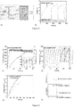
Figure 3 . Representation of the voltages at each node (terminal) of the invented energy harvester conditioning circuit. - Node M: voltage across the TENG in
figure 2b for an excitation force of 10 N at 5 Hz. The voltage maxima occur at each input mechanical cycle. - Node N1/N2: voltages across Cinput for circuits in
fig. 1a (i,ii)) showing the high-voltage hysteresis induced by the self-actuated electrostatic mechanical switch connected in series with the DC-DC converter. The converted electrical energy is accumulated into Cinput during a few tens of mechanical cycles before it is transfered to Coutput. - Node O: voltage between the switch output / the input of the DC-DC step-down converter (here a Buck circuit) and the ground. The switch is configured such as the maximum voltage is compatible with the DC-DC step-down voltage ratio.
- Node P: voltage between the DC-DC converter output / the input of the commercial low-voltage regulator (LTC3558-1) and the ground. The DC-DC converter is configured such as its output voltage is compatible with the input of the regulator.
- Node Q: regulated voltage across a 1 MΩ load. A delay is necessary to initially charge Coutput to a sufficient voltage.
-
Figure 4 . The electrical performance of the full 2-stage energy storage system with the stable charge-pump infig. 2 (1a+2) and a self-actuated electrostatic mechanical switch having a full hysteresis (the OFF input voltage equals 0V). The voltage across Cinput (Node M) (a) and its detailed view (b) versus time. The voltage across Coutput (Node P) and the 1MΩ load (Node Q) (c), and the calculated energy per input mechanical cycle in Coutput (d). -
Figure 5 . The electrical performance of a classical 1-stage stable charge pump (a half-wave rectifier) without switch and step-down DC-DC converter to drive the regulator in similar experimental conditions than infigure 4 . The experimental setup (a), and the voltage across Coutput as well as the output of the regulator (b). The energy stored in Coutput cannot supply the regulator in order to obtain a constant voltage across the 1 MΩ load. -
Figure 6 . The effect of the OFF input voltage in a 2-stage system without load and regulator and with the stable charge-pump as infig. 2 (1a+2). (a) The voltage across Cinput and voltage Coutput with a narrow hysteresis switch, (b) The voltage across Cinput and voltage across Coutput with a full-hysteresis switch (the OFF input voltage is higher than 0V) in similar experimental conditions. (c) The comparison of the 2 voltages across Coutput. The higher slope of the voltage with the switch having a narrow hysteresis demonstrates its better performance. -
Figure 7 . The voltage across Coutput and voltage across Cinput when using a 2-stage system without load and regulator, and with the unstable charge-pump (1b+2) as the rectifier and a narrow self-actuated electrostatic mechanical switch having an ON actuation voltage around 450 V. The unstable charge-pump allows reaching higher voltages across the transducer for better efficiency. The OFF actuation voltage could be optimized (here increased) by using a MEMS switch. -
Figure 8 . Example of implementations of the full-hysteresis switch and below the narrow hysteresis switch. - As represented in
figures 1 and 2 , the present invention concerns a conditioning system for a triboelectric nanogenerator (TENG) or an electrostatic kinetic energy harvester called E onfigure 1 , with two stages. - A first stage comprises:
- an AC-to-
DC voltage rectifier 1, intended to be connected to the energy harvesting device; - an input capacitor 2 Cinput, connected to the output of the AC-to-
DC voltage rectifier 1, with an input voltage across Cinput between a high-voltage terminal N, N1, N2 and a ground terminal. - A second stage comprises:
- a step-down DC-
DC converter 4, with a converter input terminal O and a converter output terminal P, - a self-actuated
electrostatic switch 3, - As represented in
figure 3 , the self-actuatedelectrostatic switch 3 creating a hysteresis of the input voltage by realizing: - a current between the two electrodes when the input voltage evolves from a ON input voltage (VON) until a OFF input voltage (VOFF),
- no current between the two electrodes when the input voltage evolves from the OFF input voltage (VOFF) until the ON input voltage (VON),
- In the invention, the preferentially hysteresis is called "narrow" and is different from the full-hysteresis of the state of the art [3], the ON input voltage VON and the OFF input voltage VOFF being close together and being non-zero and superior to zero volt, as represented on
figures 6a, 6c, 6d . Only a full-hysteresis is represented onfigure 6b . - The conditioning system presents also an output capacitor 5 Coutput, with an output voltage between a high-voltage terminal P and a ground terminal, and whose high-voltage terminal is connected to the converter output terminal.
- The input capacitor 2 Cinput can be 10 to 100 times higher than a minimum capacitance of the energy harvester.
- The output capacitor 5 Coutput can be 1000 to 10000 times higher than the input capacitor 2 Cinput.
- For instance, here in the example of the
figure 2 : - the input capacitor 2 Cinput has few nF;
- the output capacitor 5 Coutput has a few tens µF;
- the minimum capacitance of the energy harvester has a few tens Picofarad and its maximum has a few hundred of pF.
- The DC-DC converter can be a
buck converter 4+5.
In another technical realization, the DC-DC converter can be a transformer [3]. - In a technical realization, the AC-
DC voltage rectifier 1 is an unstable charge-pump, for instance from the family of the Bennet doubler. - In another technical realization, the AC-
DC voltage rectifier 1 is a stable charge pump. - The AC-to-
DC voltage rectifier 1 circuit can be made of diodes and/or capacitors. - The voltage (VON+VOFF)/2 can be equal (or close to; for instance about 80%-90% at least) the half of the saturation voltage of the stable-charge pump (it corresponds to the middle of the narrow-hysteresis) for maximum efficiency. The saturation voltage considered here is the input voltage when the
switch 3 remains OFF for a while. - The system presents a low-
voltage output regulator 8, connected to the output capacitor 5 Coutput and intended to be connected to an electrical load, with an output voltage inferior to the OFF input voltage VOFF. - At least one of the
electrodes - A
first electrode 6 is connected to the high-voltage terminal N, N1, N2 of the input capacitor 2 Cinput. - A
second electrode 7 is connected to the converter input terminal O. - Advantageously, at least one of the electrodes here the
electrode 6 infigure 8 having asharp extremity 6a, for the narrow-hysteresis switch. - Advantageously, at least one of the
electrodes moveable electrode - In a technical realization, the electrode is configured to be flexible. For instance, the moveable electrode is clamped-free and is maintained at an initial gap regarding the other electrode without voltage.
- In another technical realization, the electrode can be movable and rigid, but is attached to a mechanical spring.
- In variant not represented, the self-actuated
electrostatic switch 3 presents twoelectrodes - The electrode can be realized using silicon-based MEMS technologies
- The fixed or
movable electrode - In a technical realization, the OFF input voltage VOFF is at least 80% of the ON input voltage VON.
- The ON and OFF input voltages VON and VOFF can be superior to 50V.
- The ON input voltage VON and/or the OFF input voltage VOFF can be variable values. As represented on
figure 6a , the ON input voltage VON decreases slightly with time. - The contact actuation voltage between the two
electrodes - the initial gap between the two
electrodes - the shape of the
electrodes - the stiffness of the
movable electrode - The ambient gas breakdown voltage between the two
electrodes - the initial gap between the two
electrodes - the shape of the
electrodes - the composition and the pressure of the ambient gas;
- the material of the
electrodes 6, 7 (especially the nature and the conductivity). - The inventors adjust these parameters to realize three differents embodiments of the conditioning system of the invention, which works with hysteresis.
- In a first embodiment, the
electrodes electrodes - When the input voltage increases between the terminal N1 (or N2) and the ground terminal, the moveable electrode progressively moves towards the other one, which decreases the ambient gas breakdown voltage according to the Pashen law.
- At some moment a micro plasma occurs due to the actuation voltage and a current flow being created between the two
electrodes switch 3 is ON and the contact actuation voltage is not reached by the actuation voltage. - Then, the input voltage between the terminals N1 (or N2) and the ground terminal decreases, and the gap between the
electrodes switch 3 is OFF (no current). - In a second embodiment, the
electrodes electrode 6 is moveable. - When the input voltage between the terminals N1 (or N2) and the ground terminal increases, the actuation voltage reaches the contact actuation voltage of the
switch 3, the movable electrode comes into contact with the other one and a current flows between theelectrodes switch 3 is ON, and the gas breakdown voltage is not reached by the actuation voltage. - Then, the input voltage between the two electrodes decreases abruptly, decreasing the actuation voltage, the OFF input voltage VOFF being equal to 0V, the electrostatic force almost disappeared and the restoring spring force makes the movable electrode to separate from the fixed electrode, the contact is lost, the OFF input voltage VOFF is reached; the
switch 3 is OFF (no current). - In a third embodiment of the invention, the two
electrodes - In this case, there is no contact between the switch electrodes. When the input voltage increases, and the actuation voltage between the terminals N1 (or N2) and the input terminal O of the step-down DC-
DC converter 4 reaches the ambient gas breakdown voltage, a micro plasma occurs and a current flows between theelectrodes 6, 7: the ON input voltage VON is reached and theswitch 3 is ON. - Then, the input voltage decreases, and the actuation voltage decreases between the electrodes and at some point the plasma stopped: the OFF input voltage VOFF is reached and the
switch 3 is OFF (no current). - The energy harvester output is an AC voltage that has to be rectified using a charge pump (stable one like full or half-wave diode bridges or unstable one like a Bennet doubler) to charge a capacitor that drives the electronics. To avoid the great energy loss in the energy transfer from the transducer (harvester) to the storage capacitor due to the impedance mismatch (for instance the internal impedance of a triboelectric nanogenerator (TENG) is much higher than that of the external storage capacitor), we propose the following novel two-stage system. It can considerably increase the charging efficiency compared to other solutions that can be found in the literatures.
- The 1st stage is made of the voltage rectifying module charging a small buffer capacitor Cinput. Due to its small value (typically a few nF), it is quickly charged by the transducer to a high voltage (typically few tens to few hundreds of volts).
- The 2nd stage includes a self-actuated electrostatic mechanical switch 3 (SAEMS) and possibly a step-down DC-DC converter like a
LC buck converter 4+5. Here in the preliminary demonstrations, the SAEMS is manually made of a fixed and a moving electrodes. The initial gap between the electrodes is a key parameter defining the contact actuation voltage of the SAEMS and the micro-plasma creation (switching ON according to first embodiment) and can be controlled by a 3-axis micro-positioning platform. The switching OFF can be adjusted with the shape of the electrodes ofswitch 3. The moving electrode is connected to the high-voltage of Cinput, and the fixed one is connected to the input of a (optional)buck converter 4+5 having a large output capacitor 5 Coutput (typ. a few tens µF). This combination (SAEMS+Buck) allows to decrease the high voltage across Cinput to a reasonable value (a few volts) that can be regulated with acommercial regulator 8 in order to provide a constant low voltage to the device to be powered 9. -
Fig. 1 shows the schematic view of the invention. The output of the TENG is a high voltage (HV) impulse, with a peak around 100 V (as a typical example). The voltage across Cinput is DC, with a saturated voltage for stable rectifiers (in case of a half-wave diode bridge, VCinput can be much higher than VTENG_max if there is a high TENG capacitance variation), or a voltage without limitation for unstable rectifiers like the Bennet doubler (until the electrostatic air breakdown given by the Pashen law or any practical limits due to the electrical components) . - In case of a
stable rectifier 1, the objective of theswitch 3 is to keep VCinput around its optimal value, which is typically half of the saturation voltage. In case of anunstable rectifier 1, the objective of theswitch 3 is to keep VCinput as high as possible because a higher voltage leads to a higher harvested energy per cycle, according to HV capability of the rest of the conditioning circuit. - The objective of the DC-DC step down
converter 4+5 is to bring back the HV voltage across Cinput to the input span of the commercial regulator 8 (20 V for the device used in our experiments). - The DC-DC step down
converter 4+5 is here a Buck converter with a diode, an inductance and an output capacitor 5 Coutput. - The voltage across Coutput increases each time the
switch 3 turns ON and slightly decreases when theswitch 3 is OFF (demonstrating the following load does not dissipate more energy than the harvested one). So the load is continually powered at 3.3V through the commercial regulator 8 (or any low voltage that suits the power supply of the electrical load). -
Fig. 2 shows a schematic of such a demonstrated system with a TENG and a Buck converter.Fig. 4 shows the experimental results with a half-wave rectifier 1 and a self-actuatedelectrostatic switch 3 with full-hysteresis (i.e. VCinput re-reaches zero volt at each activation). - The voltage across Cinput is shown in
Fig. 4a , with the oscillating between -200V and 0V. The oscillating voltage across Coutput and the output of theregulator 8 are shown inFig. 4c . As explained before, the increase of VCoutput is due to the charge accumulation transferred from Cinput when theswitch 3 is ON, while the voltage decrease is caused by the power consumption of thecommercial regulator 8 and the output load (the testing probe) when theswitch 3 is OFF. - As a comparison,
Fig. 5 shows the same experiments but only withstage 1 to directly charge the storage capacitor Coutput. It is seen that thecommercial regulator 8 cannot be sustained by the energy stored in Coutput, as the output of theregulator 8 is quickly dropping to 0V once it reaches 3.3 V. In this example, only our invention allows to power thecommercial regulator 8. - Furthermore, the charging efficiency and output power can be improved with a
switch 3 having an hysteresis, as shown inFig. 6 (here Coutput is not connected to theregulator 8, this is why there is no decrease and oscillation for the voltage across Coutput). - When replacing the previous stable charge pump (the half-
wave rectifier 1a) with an unstable charge pump (aBennet doubler 1b), the charging rate and then the output power are further improved, as shown inFig. 7 (here Coutput is not connected to theregulator 8, and because the OFF input voltage VOFF of theswitch 3 is not well optimized, the oscillation of the voltage across Cinput is too large for the best efficiency). - A schematic implementations of the two switches are indicated in
Fig. 8 . For thehysteresis switch 3, the extremity of the copper wire is cut with a sharp extremity. It induces the well-known "sharp-edge" effect in electrostatic, corresponding to a large increase of the electric field at the extremity of the electrode for a given bias. This results in a decrease of the ambient gas breakdown voltages, allowing to shift fromembodiment 2 toembodiment 1, i.e. to introduce a narrow hysteresis in theswitch 3. A more precise design can be done with MEMS technologies. - To conclude, the inventors aim at optimizing the charge transfer from the energy harvester to the load (the sensor) using a 2-stage charging conditioning system with:
- a high-voltage self-actuated
electrostatic switch 3 to avoid any external control that is power consuming; in a preferred embodiment with an narrow hysteresis at high voltage, i.e. that do not bring the transducer's voltage to zero volt at each actuation, to always work around the optimized voltage; theswitch 3 can be obtained using MEMS technologies; - in a preferred embodiment an unstable charge pump to rectify the signal without (almost) any limitation in the voltage value across the transducer (except the air breakdown) to maximize the conversion efficiency; in addition it would make sure that the ON actuation voltage VON of the
electrostatic switch 3 will always be reached, even in case of the decrease in the external mechanical force of the energy harvesting device; - avoiding the use of a transformer that dissipates energy and is bulky,
- a
Buck converter 4+5 in a 2-stage architecture. -
- [1] Y. Lu, E O'Riordan, F. Cottone, S. Boisseau, F. Marty, D. Galayko, E. Blokhina and P. Basset, "A batch-fabricated electret-biased wideband MEMS vibration energy harvester with frequency-up conversion behavior powering a UHF wireless sensor node", J. Micromech. Microeng., 26 (2016) 124004
- [2] Y. Zi, J. Wang, S. Wang, S. Li, Z. Wen, H. Guo, Z. L. Wang, "Effective energy storage from a triboelectric nanogenerator."Nature communications. 2016 .
- [3] F. Xi, Y. Pang, W. Li, T. Jiang, L. Zhang, T. Guo, G. Liu, C. Zhang and Z. L. Wang, "Universal power management strategy for triboelectric nanogenerator", Nano Energy 37 (2017) 168-76
- [4] S. Niu, X. Wang, F. Yi, Y. S. Zhou, Z. L. Wang, "A universal self-charging system driven by random biomechanical energy for sustainable operation of mobile electronics." Nature communications. 2015 .
a first electrode being connected to the high-voltage terminal of the input capacitor Cinput, and a second electrode being connected to the converter input terminal,
the self-actuated electrostatic switch creating an hysteresis of the input voltage by realizing :
at least one of the electrodes having an extremity configured for generating an ambient gas breakdown voltage which is superior or inferior to the contact actuation voltage between the two electrodes,
Claims (17)
- Conditioning system for a triboelectric nanogenerator or an electrostatic kinetic energy harvester, with:• a first stage comprising:- an AC-to-DC voltage rectifier (1), intended to be connected to the energy harvesting device (E);- an input capacitor (2) Cinput, connected to the output of the AC-to-DC voltage rectifier (1); with an input voltage across Cinput between a high voltage terminal (N, N1, N2) and a ground terminal,• a second stage comprising:- a self-actuated electrostatic switch (3),- a step-down DC-DC converter (4), with a converter input terminal (O) and a converter output terminal (P),the self-actuated electrostatic switch (3) having an actuation voltage driven by the high-voltage terminal (N, N1, N2) of the input capacitor (2) Cinput and the converter input terminal (O),
a first electrode (5) being connected to the high-voltage terminal (N, N1, N2) of the input capacitor (2) Cinput, and a second electrode (6) being connected to the converter input terminal O,
the self-actuated electrostatic switch (3) creating an hysteresis of the input voltage by realizing :- a current between the two electrodes (6, 7) when the input voltage evolves from a ON input voltage VON until a OFF input voltage VOFF,- no current between the two electrodes (6, 7) when the input voltage evolves from the OFF input voltage VOFF until the ON input voltage VON,the ON input voltage VON being higher than the OFF input voltage VOFF, the OFF input voltage VOFF being preferentially superior to 0V,
at least one of the electrodes (6, 7) having an extremity configured for generating an ambient gas breakdown voltage which is superior or inferior to the contact actuation voltage between the two electrodes (6, 7),- an output capacitor (5) Coutput, with an output voltage between a high-voltage terminal and a ground terminal, and whose high-voltage terminal is connected to the converter output terminal P. - Conditioning system according to claim 1, wherein at least one of the electrodes (6, 7) is moveable and an elastic restoring force acts on the moveable electrode (6, 7) which is flexible and / or is attached to a spring.
- Conditioning system according to claim 2, wherein the contact actuation voltage between the two electrodes (6, 7) is configured at least by:- the initial gap between the two electrodes (6, 7);- the shape of the electrodes (6, 7) ;- the stiffness of the movable electrode (6, 7).
- Conditioning system according to claims 1-2, wherein the ambient gas breakdown voltage between the two electrodes (6, 7) is configured at least by:- the initial gap between the two electrodes (6, 7) ;- the shape of the electrodes (6, 7) ;- the composition and the pressure of the ambient gas;- the material of the electrodes (6, 7).
- Conditioning system according to claims 3- 4, wherein the electrodes (6, 7) are configured so that the contact actuation voltage is higher than the gas breakdown voltage.
- Conditioning system according to claims 3-4, wherein the electrodes (6, 7) are configured so that the contact actuation voltage is smaller than the gas breakdown voltage.
- Conditioning system according to claims 1-6, wherein at least one of the electrodes (6, 7) having a sharp extremity (6a).
- Conditioning system according to one of claims 1, 1 with 4, or 1 with 7, wherein the two electrodes (6, 7) are fixed.
- Conditioning system according to claims 1-8, wherein:- the input capacitor (2) Cinput is 10 to 100 times higher than a minimum capacitance of the triboelectric nanogenerator or an electrostatic kinetic energy harvester,- the output capacitor (5) Coutput is 1000 to 10000 times higher than the input capacitor (2) Cinput.
- Conditioning system according to claims 1-9, wherein a DC-DC converter (4, 5) is a buck converter.
- Conditioning system according to claims 1-10, wherein the AC-DC voltage rectifier (1) is an unstable charge-pump (1b), for instance from the family of the Bennet doubler.
- Conditioning system according to claims 1-10, wherein the AC-DC voltage rectifier (1) is a stable charge pump (1a), for instance a half or full-wave diode bridge.
- Conditioning system according to claim 12, wherein half of the sum of the ON input voltage VON and the OFF input voltage VOFF is equal or close to the half of the saturation voltage of the stable-charge pump (1a).
- Conditioning system according to claims 1-13, wherein the system presents a low-voltage output regulator (8), connected to the output capacitor (5) Coutput and intended to be connected to an electrical load, with a regulator output voltage inferior to the OFF input voltage VOFF.
- Conditioning system according to claims 1-14, wherein the OFF input voltage VOFF is at least 80% of the ON input voltage VON.
- Conditioning system according to claims 1-15, wherein The ON and OFF input voltages VON and VOFF can be superior to 50V.
- Device with triboelectric nanogenerator or an electrostatic kinetic energy harvester connected to a conditioning system according to claims 1-16.
Priority Applications (3)
| Application Number | Priority Date | Filing Date | Title |
|---|---|---|---|
| EP18020610.4A EP3654513A1 (en) | 2018-11-15 | 2018-11-15 | Conditioning system for a triboelectric nanogenerator or an electrostatic kinetic energy harvester |
| EP19780269.7A EP3881419A1 (en) | 2018-11-15 | 2019-10-08 | Conditioning system for a triboelectric nanogenerator or an electrostatic kinetic energy harvestersystem for a triboelectric nanogenerator or an electrostatic kinetic energy harvester |
| PCT/EP2019/077251 WO2020099030A1 (en) | 2018-11-15 | 2019-10-08 | Conditioning system for a triboelectric nanogenerator or an electrostatic kinetic energy harvestersystem for a triboelectric nanogenerator or an electrostatic kinetic energy harvester |
Applications Claiming Priority (1)
| Application Number | Priority Date | Filing Date | Title |
|---|---|---|---|
| EP18020610.4A EP3654513A1 (en) | 2018-11-15 | 2018-11-15 | Conditioning system for a triboelectric nanogenerator or an electrostatic kinetic energy harvester |
Publications (1)
| Publication Number | Publication Date |
|---|---|
| EP3654513A1 true EP3654513A1 (en) | 2020-05-20 |
Family
ID=64401957
Family Applications (2)
| Application Number | Title | Priority Date | Filing Date |
|---|---|---|---|
| EP18020610.4A Withdrawn EP3654513A1 (en) | 2018-11-15 | 2018-11-15 | Conditioning system for a triboelectric nanogenerator or an electrostatic kinetic energy harvester |
| EP19780269.7A Pending EP3881419A1 (en) | 2018-11-15 | 2019-10-08 | Conditioning system for a triboelectric nanogenerator or an electrostatic kinetic energy harvestersystem for a triboelectric nanogenerator or an electrostatic kinetic energy harvester |
Family Applications After (1)
| Application Number | Title | Priority Date | Filing Date |
|---|---|---|---|
| EP19780269.7A Pending EP3881419A1 (en) | 2018-11-15 | 2019-10-08 | Conditioning system for a triboelectric nanogenerator or an electrostatic kinetic energy harvestersystem for a triboelectric nanogenerator or an electrostatic kinetic energy harvester |
Country Status (2)
| Country | Link |
|---|---|
| EP (2) | EP3654513A1 (en) |
| WO (1) | WO2020099030A1 (en) |
Families Citing this family (1)
| Publication number | Priority date | Publication date | Assignee | Title |
|---|---|---|---|---|
| CN113938050B (en) * | 2021-09-13 | 2024-06-11 | 浙江大学 | A triboelectric nanogenerator with high sensitivity and instantaneous self-powered wireless sensing system |
Citations (1)
| Publication number | Priority date | Publication date | Assignee | Title |
|---|---|---|---|---|
| WO2013055238A1 (en) * | 2011-10-14 | 2013-04-18 | Auckland Uniservices Limited | Passively switched converter and circuits including same |
Family Cites Families (2)
| Publication number | Priority date | Publication date | Assignee | Title |
|---|---|---|---|---|
| WO2014117161A1 (en) * | 2013-01-28 | 2014-07-31 | Massachusetts Institute Of Technology | Electromechanical device |
| CN106602687A (en) * | 2015-10-19 | 2017-04-26 | 北京纳米能源与系统研究所 | Energy management method, circuit and device for friction nano-generators |
-
2018
- 2018-11-15 EP EP18020610.4A patent/EP3654513A1/en not_active Withdrawn
-
2019
- 2019-10-08 EP EP19780269.7A patent/EP3881419A1/en active Pending
- 2019-10-08 WO PCT/EP2019/077251 patent/WO2020099030A1/en not_active Ceased
Patent Citations (1)
| Publication number | Priority date | Publication date | Assignee | Title |
|---|---|---|---|---|
| WO2013055238A1 (en) * | 2011-10-14 | 2013-04-18 | Auckland Uniservices Limited | Passively switched converter and circuits including same |
Non-Patent Citations (5)
| Title |
|---|
| F. XI; Y. PANG; W. LI; T. JIANG; L. ZHANG; T. GUO; G. LIU; C. ZHANG; Z. L. WANG: "Universal power management strategy for triboelectric nanogenerator", NANO ENERGY, vol. 37, 2017, pages 168 - 76 |
| LU Y ET AL: "A batch-fabricated electret-biased wideband MEMS vibration energy harvester with frequency-up conversion behavior powering a UHF wireless sensor node", JOURNAL OF MICROMECHANICS & MICROENGINEERING, INSTITUTE OF PHYSICS PUBLISHING, BRISTOL, GB, vol. 26, no. 12, 29 September 2016 (2016-09-29), pages 124004, XP020310877, ISSN: 0960-1317, [retrieved on 20160929], DOI: 10.1088/0960-1317/26/12/124004 * |
| S. NIU; X. WANG; F. YI; Y. S. ZHOU; Z. L. WANG: "A universal self-charging system driven by random biomechanical energy for sustainable operation of mobile electronics", NATURE COMMUNICATIONS, vol. 6, 11 December 2015 (2015-12-11), pages 8975 |
| Y. LU; E O'RIORDAN; F. COTTONE; S. BOISSEAU; F. MARTY; D. GALAYKO; E. BLOKHINA; P. BASSET: "A batch-fabricated electret-biased wideband MEMS vibration energy harvester with frequency-up conversion behavior powering a UHF wireless sensor node", J. MICROMECH. MICROENG., vol. 26, 2016, pages 124004, XP020310877, DOI: doi:10.1088/0960-1317/26/12/124004 |
| Y. ZI; J. WANG; S. WANG; S. LI; Z. WEN; H. GUO; Z. L. WANG: "Effective energy storage from a triboelectric nanogenerator", NATURE COMMUNICATIONS, vol. 7, 11 March 2016 (2016-03-11), pages 10987 |
Also Published As
| Publication number | Publication date |
|---|---|
| WO2020099030A1 (en) | 2020-05-22 |
| EP3881419A1 (en) | 2021-09-22 |
Similar Documents
| Publication | Publication Date | Title |
|---|---|---|
| Szarka et al. | Review of power conditioning for kinetic energy harvesting systems | |
| Rahimi et al. | Fully self-powered electromagnetic energy harvesting system with highly efficient dual rail output | |
| CN103378749B (en) | Power circuit | |
| Liu et al. | An intermittent self-powered energy harvesting system from low-frequency hand shaking | |
| CN110289757B (en) | Single inductance DC-DC converter with regulated output and energy harvesting system | |
| US20100090669A1 (en) | Buck dc-to-dc converter and method | |
| CN101689807A (en) | Multi-output switching power supply device | |
| WO2007149859A2 (en) | Dc-dc converter for low voltage power source | |
| JP2016127656A (en) | Power storage device that stores power generated by energy harvesting elements | |
| Cheng et al. | A voltage-multiplying self-powered AC/DC converter with 0.35-V minimum input voltage for energy harvesting applications | |
| TW201832038A (en) | Variable power capacitor for RF power applications | |
| EP2808975A1 (en) | Inductive power transmission device | |
| Zhang et al. | A conditioning system for high-voltage electrostatic/triboelectric energy harvesters using bennet doubler and self-actuated hysteresis switch | |
| WO2018074144A1 (en) | Power supply circuit | |
| EP3654513A1 (en) | Conditioning system for a triboelectric nanogenerator or an electrostatic kinetic energy harvester | |
| Zhang et al. | A self-sustained energy storage system with an electrostatic automatic switch and a buck converter for triboelectric nanogenerators | |
| JP2019161975A (en) | Power storage device and power storage system | |
| Edla et al. | Self-powered boost-converter for power optimisation and piezo garden lights | |
| CN108879919B (en) | Piezoelectric electromagnetic composite energy harvester energy management circuit for powering wireless sensors | |
| JPWO2020075371A1 (en) | Power supply circuits, start-up circuits, power generators, and electronic devices | |
| Chen et al. | Self-powered multi-PZTs energy harvesting interface based on extensible PSSHI rectification with power region optimization technique | |
| Zhang et al. | High-voltage MEMS plasma switch for boosting the energy transfer efficiency in triboelectric nanogenerators | |
| JP2015195651A (en) | Environmental power generating set | |
| Savarimuthu et al. | Design and implementation of piezoelectric energy harvesting circuit | |
| Lo et al. | Circuit design considerations for regulating energy generated by dielectric elastomer generators |
Legal Events
| Date | Code | Title | Description |
|---|---|---|---|
| PUAI | Public reference made under article 153(3) epc to a published international application that has entered the european phase |
Free format text: ORIGINAL CODE: 0009012 |
|
| STAA | Information on the status of an ep patent application or granted ep patent |
Free format text: STATUS: THE APPLICATION HAS BEEN PUBLISHED |
|
| AK | Designated contracting states |
Kind code of ref document: A1 Designated state(s): AL AT BE BG CH CY CZ DE DK EE ES FI FR GB GR HR HU IE IS IT LI LT LU LV MC MK MT NL NO PL PT RO RS SE SI SK SM TR |
|
| AX | Request for extension of the european patent |
Extension state: BA ME |
|
| STAA | Information on the status of an ep patent application or granted ep patent |
Free format text: STATUS: THE APPLICATION IS DEEMED TO BE WITHDRAWN |
|
| 18D | Application deemed to be withdrawn |
Effective date: 20201121 |