EP3654447A1 - Battery system and moving body - Google Patents
Battery system and moving body Download PDFInfo
- Publication number
- EP3654447A1 EP3654447A1 EP18832707.6A EP18832707A EP3654447A1 EP 3654447 A1 EP3654447 A1 EP 3654447A1 EP 18832707 A EP18832707 A EP 18832707A EP 3654447 A1 EP3654447 A1 EP 3654447A1
- Authority
- EP
- European Patent Office
- Prior art keywords
- oxygen
- enclosure case
- battery
- lithium
- battery system
- Prior art date
- Legal status (The legal status is an assumption and is not a legal conclusion. Google has not performed a legal analysis and makes no representation as to the accuracy of the status listed.)
- Granted
Links
Images


Classifications
-
- H—ELECTRICITY
- H01—ELECTRIC ELEMENTS
- H01M—PROCESSES OR MEANS, e.g. BATTERIES, FOR THE DIRECT CONVERSION OF CHEMICAL ENERGY INTO ELECTRICAL ENERGY
- H01M10/00—Secondary cells; Manufacture thereof
- H01M10/42—Methods or arrangements for servicing or maintenance of secondary cells or secondary half-cells
- H01M10/46—Accumulators structurally combined with charging apparatus
- H01M10/465—Accumulators structurally combined with charging apparatus with solar battery as charging system
-
- B—PERFORMING OPERATIONS; TRANSPORTING
- B60—VEHICLES IN GENERAL
- B60L—PROPULSION OF ELECTRICALLY-PROPELLED VEHICLES; SUPPLYING ELECTRIC POWER FOR AUXILIARY EQUIPMENT OF ELECTRICALLY-PROPELLED VEHICLES; ELECTRODYNAMIC BRAKE SYSTEMS FOR VEHICLES IN GENERAL; MAGNETIC SUSPENSION OR LEVITATION FOR VEHICLES; MONITORING OPERATING VARIABLES OF ELECTRICALLY-PROPELLED VEHICLES; ELECTRIC SAFETY DEVICES FOR ELECTRICALLY-PROPELLED VEHICLES
- B60L50/00—Electric propulsion with power supplied within the vehicle
- B60L50/50—Electric propulsion with power supplied within the vehicle using propulsion power supplied by batteries or fuel cells
- B60L50/60—Electric propulsion with power supplied within the vehicle using propulsion power supplied by batteries or fuel cells using power supplied by batteries
- B60L50/64—Constructional details of batteries specially adapted for electric vehicles
-
- B—PERFORMING OPERATIONS; TRANSPORTING
- B60—VEHICLES IN GENERAL
- B60L—PROPULSION OF ELECTRICALLY-PROPELLED VEHICLES; SUPPLYING ELECTRIC POWER FOR AUXILIARY EQUIPMENT OF ELECTRICALLY-PROPELLED VEHICLES; ELECTRODYNAMIC BRAKE SYSTEMS FOR VEHICLES IN GENERAL; MAGNETIC SUSPENSION OR LEVITATION FOR VEHICLES; MONITORING OPERATING VARIABLES OF ELECTRICALLY-PROPELLED VEHICLES; ELECTRIC SAFETY DEVICES FOR ELECTRICALLY-PROPELLED VEHICLES
- B60L53/00—Methods of charging batteries, specially adapted for electric vehicles; Charging stations or on-board charging equipment therefor; Exchange of energy storage elements in electric vehicles
- B60L53/50—Charging stations characterised by energy-storage or power-generation means
- B60L53/51—Photovoltaic means
-
- B—PERFORMING OPERATIONS; TRANSPORTING
- B60—VEHICLES IN GENERAL
- B60L—PROPULSION OF ELECTRICALLY-PROPELLED VEHICLES; SUPPLYING ELECTRIC POWER FOR AUXILIARY EQUIPMENT OF ELECTRICALLY-PROPELLED VEHICLES; ELECTRODYNAMIC BRAKE SYSTEMS FOR VEHICLES IN GENERAL; MAGNETIC SUSPENSION OR LEVITATION FOR VEHICLES; MONITORING OPERATING VARIABLES OF ELECTRICALLY-PROPELLED VEHICLES; ELECTRIC SAFETY DEVICES FOR ELECTRICALLY-PROPELLED VEHICLES
- B60L58/00—Methods or circuit arrangements for monitoring or controlling batteries or fuel cells, specially adapted for electric vehicles
- B60L58/10—Methods or circuit arrangements for monitoring or controlling batteries or fuel cells, specially adapted for electric vehicles for monitoring or controlling batteries
- B60L58/24—Methods or circuit arrangements for monitoring or controlling batteries or fuel cells, specially adapted for electric vehicles for monitoring or controlling batteries for controlling the temperature of batteries
- B60L58/27—Methods or circuit arrangements for monitoring or controlling batteries or fuel cells, specially adapted for electric vehicles for monitoring or controlling batteries for controlling the temperature of batteries by heating
-
- H—ELECTRICITY
- H01—ELECTRIC ELEMENTS
- H01M—PROCESSES OR MEANS, e.g. BATTERIES, FOR THE DIRECT CONVERSION OF CHEMICAL ENERGY INTO ELECTRICAL ENERGY
- H01M10/00—Secondary cells; Manufacture thereof
- H01M10/42—Methods or arrangements for servicing or maintenance of secondary cells or secondary half-cells
- H01M10/425—Structural combination with electronic components, e.g. electronic circuits integrated to the outside of the casing
-
- H—ELECTRICITY
- H01—ELECTRIC ELEMENTS
- H01M—PROCESSES OR MEANS, e.g. BATTERIES, FOR THE DIRECT CONVERSION OF CHEMICAL ENERGY INTO ELECTRICAL ENERGY
- H01M10/00—Secondary cells; Manufacture thereof
- H01M10/42—Methods or arrangements for servicing or maintenance of secondary cells or secondary half-cells
- H01M10/44—Methods for charging or discharging
-
- H—ELECTRICITY
- H01—ELECTRIC ELEMENTS
- H01M—PROCESSES OR MEANS, e.g. BATTERIES, FOR THE DIRECT CONVERSION OF CHEMICAL ENERGY INTO ELECTRICAL ENERGY
- H01M10/00—Secondary cells; Manufacture thereof
- H01M10/42—Methods or arrangements for servicing or maintenance of secondary cells or secondary half-cells
- H01M10/48—Accumulators combined with arrangements for measuring, testing or indicating the condition of cells, e.g. the level or density of the electrolyte
-
- H—ELECTRICITY
- H01—ELECTRIC ELEMENTS
- H01M—PROCESSES OR MEANS, e.g. BATTERIES, FOR THE DIRECT CONVERSION OF CHEMICAL ENERGY INTO ELECTRICAL ENERGY
- H01M10/00—Secondary cells; Manufacture thereof
- H01M10/42—Methods or arrangements for servicing or maintenance of secondary cells or secondary half-cells
- H01M10/48—Accumulators combined with arrangements for measuring, testing or indicating the condition of cells, e.g. the level or density of the electrolyte
- H01M10/486—Accumulators combined with arrangements for measuring, testing or indicating the condition of cells, e.g. the level or density of the electrolyte for measuring temperature
-
- H—ELECTRICITY
- H01—ELECTRIC ELEMENTS
- H01M—PROCESSES OR MEANS, e.g. BATTERIES, FOR THE DIRECT CONVERSION OF CHEMICAL ENERGY INTO ELECTRICAL ENERGY
- H01M10/00—Secondary cells; Manufacture thereof
- H01M10/60—Heating or cooling; Temperature control
- H01M10/61—Types of temperature control
- H01M10/613—Cooling or keeping cold
-
- H—ELECTRICITY
- H01—ELECTRIC ELEMENTS
- H01M—PROCESSES OR MEANS, e.g. BATTERIES, FOR THE DIRECT CONVERSION OF CHEMICAL ENERGY INTO ELECTRICAL ENERGY
- H01M10/00—Secondary cells; Manufacture thereof
- H01M10/60—Heating or cooling; Temperature control
- H01M10/61—Types of temperature control
- H01M10/615—Heating or keeping warm
-
- H—ELECTRICITY
- H01—ELECTRIC ELEMENTS
- H01M—PROCESSES OR MEANS, e.g. BATTERIES, FOR THE DIRECT CONVERSION OF CHEMICAL ENERGY INTO ELECTRICAL ENERGY
- H01M10/00—Secondary cells; Manufacture thereof
- H01M10/60—Heating or cooling; Temperature control
- H01M10/62—Heating or cooling; Temperature control specially adapted for specific applications
- H01M10/625—Vehicles
-
- H—ELECTRICITY
- H01—ELECTRIC ELEMENTS
- H01M—PROCESSES OR MEANS, e.g. BATTERIES, FOR THE DIRECT CONVERSION OF CHEMICAL ENERGY INTO ELECTRICAL ENERGY
- H01M10/00—Secondary cells; Manufacture thereof
- H01M10/60—Heating or cooling; Temperature control
- H01M10/63—Control systems
- H01M10/633—Control systems characterised by algorithms, flow charts, software details or the like
-
- H—ELECTRICITY
- H01—ELECTRIC ELEMENTS
- H01M—PROCESSES OR MEANS, e.g. BATTERIES, FOR THE DIRECT CONVERSION OF CHEMICAL ENERGY INTO ELECTRICAL ENERGY
- H01M10/00—Secondary cells; Manufacture thereof
- H01M10/60—Heating or cooling; Temperature control
- H01M10/65—Means for temperature control structurally associated with the cells
- H01M10/656—Means for temperature control structurally associated with the cells characterised by the type of heat-exchange fluid
- H01M10/6561—Gases
- H01M10/6563—Gases with forced flow, e.g. by blowers
-
- H—ELECTRICITY
- H01—ELECTRIC ELEMENTS
- H01M—PROCESSES OR MEANS, e.g. BATTERIES, FOR THE DIRECT CONVERSION OF CHEMICAL ENERGY INTO ELECTRICAL ENERGY
- H01M10/00—Secondary cells; Manufacture thereof
- H01M10/60—Heating or cooling; Temperature control
- H01M10/65—Means for temperature control structurally associated with the cells
- H01M10/657—Means for temperature control structurally associated with the cells by electric or electromagnetic means
-
- H—ELECTRICITY
- H01—ELECTRIC ELEMENTS
- H01M—PROCESSES OR MEANS, e.g. BATTERIES, FOR THE DIRECT CONVERSION OF CHEMICAL ENERGY INTO ELECTRICAL ENERGY
- H01M10/00—Secondary cells; Manufacture thereof
- H01M10/60—Heating or cooling; Temperature control
- H01M10/65—Means for temperature control structurally associated with the cells
- H01M10/657—Means for temperature control structurally associated with the cells by electric or electromagnetic means
- H01M10/6571—Resistive heaters
-
- H—ELECTRICITY
- H01—ELECTRIC ELEMENTS
- H01M—PROCESSES OR MEANS, e.g. BATTERIES, FOR THE DIRECT CONVERSION OF CHEMICAL ENERGY INTO ELECTRICAL ENERGY
- H01M10/00—Secondary cells; Manufacture thereof
- H01M10/60—Heating or cooling; Temperature control
- H01M10/65—Means for temperature control structurally associated with the cells
- H01M10/658—Means for temperature control structurally associated with the cells by thermal insulation or shielding
-
- H—ELECTRICITY
- H01—ELECTRIC ELEMENTS
- H01M—PROCESSES OR MEANS, e.g. BATTERIES, FOR THE DIRECT CONVERSION OF CHEMICAL ENERGY INTO ELECTRICAL ENERGY
- H01M12/00—Hybrid cells; Manufacture thereof
- H01M12/02—Details
-
- H—ELECTRICITY
- H01—ELECTRIC ELEMENTS
- H01M—PROCESSES OR MEANS, e.g. BATTERIES, FOR THE DIRECT CONVERSION OF CHEMICAL ENERGY INTO ELECTRICAL ENERGY
- H01M12/00—Hybrid cells; Manufacture thereof
- H01M12/08—Hybrid cells; Manufacture thereof composed of a half-cell of a fuel-cell type and a half-cell of the secondary-cell type
-
- H—ELECTRICITY
- H01—ELECTRIC ELEMENTS
- H01M—PROCESSES OR MEANS, e.g. BATTERIES, FOR THE DIRECT CONVERSION OF CHEMICAL ENERGY INTO ELECTRICAL ENERGY
- H01M4/00—Electrodes
- H01M4/02—Electrodes composed of, or comprising, active material
- H01M4/36—Selection of substances as active materials, active masses, active liquids
- H01M4/38—Selection of substances as active materials, active masses, active liquids of elements or alloys
- H01M4/381—Alkaline or alkaline earth metals elements
- H01M4/382—Lithium
-
- H—ELECTRICITY
- H01—ELECTRIC ELEMENTS
- H01M—PROCESSES OR MEANS, e.g. BATTERIES, FOR THE DIRECT CONVERSION OF CHEMICAL ENERGY INTO ELECTRICAL ENERGY
- H01M50/00—Constructional details or processes of manufacture of the non-active parts of electrochemical cells other than fuel cells, e.g. hybrid cells
- H01M50/10—Primary casings; Jackets or wrappings
- H01M50/138—Primary casings; Jackets or wrappings adapted for specific cells, e.g. electrochemical cells operating at high temperature
- H01M50/1385—Hybrid cells
-
- H—ELECTRICITY
- H01—ELECTRIC ELEMENTS
- H01M—PROCESSES OR MEANS, e.g. BATTERIES, FOR THE DIRECT CONVERSION OF CHEMICAL ENERGY INTO ELECTRICAL ENERGY
- H01M50/00—Constructional details or processes of manufacture of the non-active parts of electrochemical cells other than fuel cells, e.g. hybrid cells
- H01M50/20—Mountings; Secondary casings or frames; Racks, modules or packs; Suspension devices; Shock absorbers; Transport or carrying devices; Holders
- H01M50/249—Mountings; Secondary casings or frames; Racks, modules or packs; Suspension devices; Shock absorbers; Transport or carrying devices; Holders specially adapted for aircraft or vehicles, e.g. cars or trains
-
- H—ELECTRICITY
- H01—ELECTRIC ELEMENTS
- H01M—PROCESSES OR MEANS, e.g. BATTERIES, FOR THE DIRECT CONVERSION OF CHEMICAL ENERGY INTO ELECTRICAL ENERGY
- H01M8/00—Fuel cells; Manufacture thereof
- H01M8/04—Auxiliary arrangements, e.g. for control of pressure or for circulation of fluids
- H01M8/04082—Arrangements for control of reactant parameters, e.g. pressure or concentration
- H01M8/04089—Arrangements for control of reactant parameters, e.g. pressure or concentration of gaseous reactants
-
- H—ELECTRICITY
- H01—ELECTRIC ELEMENTS
- H01M—PROCESSES OR MEANS, e.g. BATTERIES, FOR THE DIRECT CONVERSION OF CHEMICAL ENERGY INTO ELECTRICAL ENERGY
- H01M8/00—Fuel cells; Manufacture thereof
- H01M8/04—Auxiliary arrangements, e.g. for control of pressure or for circulation of fluids
- H01M8/04082—Arrangements for control of reactant parameters, e.g. pressure or concentration
- H01M8/04201—Reactant storage and supply, e.g. means for feeding, pipes
-
- H—ELECTRICITY
- H01—ELECTRIC ELEMENTS
- H01M—PROCESSES OR MEANS, e.g. BATTERIES, FOR THE DIRECT CONVERSION OF CHEMICAL ENERGY INTO ELECTRICAL ENERGY
- H01M8/00—Fuel cells; Manufacture thereof
- H01M8/04—Auxiliary arrangements, e.g. for control of pressure or for circulation of fluids
- H01M8/04298—Processes for controlling fuel cells or fuel cell systems
- H01M8/04694—Processes for controlling fuel cells or fuel cell systems characterised by variables to be controlled
- H01M8/04701—Temperature
- H01M8/04708—Temperature of fuel cell reactants
-
- H—ELECTRICITY
- H01—ELECTRIC ELEMENTS
- H01M—PROCESSES OR MEANS, e.g. BATTERIES, FOR THE DIRECT CONVERSION OF CHEMICAL ENERGY INTO ELECTRICAL ENERGY
- H01M8/00—Fuel cells; Manufacture thereof
- H01M8/04—Auxiliary arrangements, e.g. for control of pressure or for circulation of fluids
- H01M8/04298—Processes for controlling fuel cells or fuel cell systems
- H01M8/04694—Processes for controlling fuel cells or fuel cell systems characterised by variables to be controlled
- H01M8/04746—Pressure; Flow
- H01M8/04753—Pressure; Flow of fuel cell reactants
-
- B—PERFORMING OPERATIONS; TRANSPORTING
- B60—VEHICLES IN GENERAL
- B60L—PROPULSION OF ELECTRICALLY-PROPELLED VEHICLES; SUPPLYING ELECTRIC POWER FOR AUXILIARY EQUIPMENT OF ELECTRICALLY-PROPELLED VEHICLES; ELECTRODYNAMIC BRAKE SYSTEMS FOR VEHICLES IN GENERAL; MAGNETIC SUSPENSION OR LEVITATION FOR VEHICLES; MONITORING OPERATING VARIABLES OF ELECTRICALLY-PROPELLED VEHICLES; ELECTRIC SAFETY DEVICES FOR ELECTRICALLY-PROPELLED VEHICLES
- B60L2200/00—Type of vehicles
- B60L2200/10—Air crafts
-
- H—ELECTRICITY
- H01—ELECTRIC ELEMENTS
- H01M—PROCESSES OR MEANS, e.g. BATTERIES, FOR THE DIRECT CONVERSION OF CHEMICAL ENERGY INTO ELECTRICAL ENERGY
- H01M2220/00—Batteries for particular applications
- H01M2220/20—Batteries in motive systems, e.g. vehicle, ship, plane
-
- Y—GENERAL TAGGING OF NEW TECHNOLOGICAL DEVELOPMENTS; GENERAL TAGGING OF CROSS-SECTIONAL TECHNOLOGIES SPANNING OVER SEVERAL SECTIONS OF THE IPC; TECHNICAL SUBJECTS COVERED BY FORMER USPC CROSS-REFERENCE ART COLLECTIONS [XRACs] AND DIGESTS
- Y02—TECHNOLOGIES OR APPLICATIONS FOR MITIGATION OR ADAPTATION AGAINST CLIMATE CHANGE
- Y02E—REDUCTION OF GREENHOUSE GAS [GHG] EMISSIONS, RELATED TO ENERGY GENERATION, TRANSMISSION OR DISTRIBUTION
- Y02E60/00—Enabling technologies; Technologies with a potential or indirect contribution to GHG emissions mitigation
- Y02E60/10—Energy storage using batteries
-
- Y—GENERAL TAGGING OF NEW TECHNOLOGICAL DEVELOPMENTS; GENERAL TAGGING OF CROSS-SECTIONAL TECHNOLOGIES SPANNING OVER SEVERAL SECTIONS OF THE IPC; TECHNICAL SUBJECTS COVERED BY FORMER USPC CROSS-REFERENCE ART COLLECTIONS [XRACs] AND DIGESTS
- Y02—TECHNOLOGIES OR APPLICATIONS FOR MITIGATION OR ADAPTATION AGAINST CLIMATE CHANGE
- Y02E—REDUCTION OF GREENHOUSE GAS [GHG] EMISSIONS, RELATED TO ENERGY GENERATION, TRANSMISSION OR DISTRIBUTION
- Y02E60/00—Enabling technologies; Technologies with a potential or indirect contribution to GHG emissions mitigation
- Y02E60/30—Hydrogen technology
- Y02E60/50—Fuel cells
-
- Y—GENERAL TAGGING OF NEW TECHNOLOGICAL DEVELOPMENTS; GENERAL TAGGING OF CROSS-SECTIONAL TECHNOLOGIES SPANNING OVER SEVERAL SECTIONS OF THE IPC; TECHNICAL SUBJECTS COVERED BY FORMER USPC CROSS-REFERENCE ART COLLECTIONS [XRACs] AND DIGESTS
- Y02—TECHNOLOGIES OR APPLICATIONS FOR MITIGATION OR ADAPTATION AGAINST CLIMATE CHANGE
- Y02T—CLIMATE CHANGE MITIGATION TECHNOLOGIES RELATED TO TRANSPORTATION
- Y02T10/00—Road transport of goods or passengers
- Y02T10/60—Other road transportation technologies with climate change mitigation effect
- Y02T10/70—Energy storage systems for electromobility, e.g. batteries
-
- Y—GENERAL TAGGING OF NEW TECHNOLOGICAL DEVELOPMENTS; GENERAL TAGGING OF CROSS-SECTIONAL TECHNOLOGIES SPANNING OVER SEVERAL SECTIONS OF THE IPC; TECHNICAL SUBJECTS COVERED BY FORMER USPC CROSS-REFERENCE ART COLLECTIONS [XRACs] AND DIGESTS
- Y02—TECHNOLOGIES OR APPLICATIONS FOR MITIGATION OR ADAPTATION AGAINST CLIMATE CHANGE
- Y02T—CLIMATE CHANGE MITIGATION TECHNOLOGIES RELATED TO TRANSPORTATION
- Y02T10/00—Road transport of goods or passengers
- Y02T10/60—Other road transportation technologies with climate change mitigation effect
- Y02T10/7072—Electromobility specific charging systems or methods for batteries, ultracapacitors, supercapacitors or double-layer capacitors
-
- Y—GENERAL TAGGING OF NEW TECHNOLOGICAL DEVELOPMENTS; GENERAL TAGGING OF CROSS-SECTIONAL TECHNOLOGIES SPANNING OVER SEVERAL SECTIONS OF THE IPC; TECHNICAL SUBJECTS COVERED BY FORMER USPC CROSS-REFERENCE ART COLLECTIONS [XRACs] AND DIGESTS
- Y02—TECHNOLOGIES OR APPLICATIONS FOR MITIGATION OR ADAPTATION AGAINST CLIMATE CHANGE
- Y02T—CLIMATE CHANGE MITIGATION TECHNOLOGIES RELATED TO TRANSPORTATION
- Y02T90/00—Enabling technologies or technologies with a potential or indirect contribution to GHG emissions mitigation
- Y02T90/10—Technologies relating to charging of electric vehicles
- Y02T90/12—Electric charging stations
Definitions
- the present invention relates to a battery system and a moving body.
- Lithium-air batteries have been known, in which oxygen in the air is used as a positive electrode active material and lithium is used as a negative electrode active material (see Patent Document 1, for example).
- Patent Document 1 International Publication WO 2015/115480
- a first aspect of the present invention provides a battery system.
- the battery system may include a lithium-oxygen battery.
- the battery system may include an oxygen compressing unit configured to compress oxygen released from the lithium-oxygen battery.
- the battery system may include a storage unit configured to store oxygen compressed by the oxygen compressing unit.
- the battery system may include an oxygen supplying unit configured to supply oxygen stored in the storage unit to the lithium-oxygen battery.
- the battery system may further include an enclosure case enclosing the lithium-oxygen battery, and the oxygen compressing unit and the oxygen supplying unit may be connected to the enclosure case.
- the oxygen supplying unit may supply oxygen stored in the storage unit to the enclosure case, and the battery system may further include a blowing fan disposed in the enclosure case and configured to blow oxygen supplied by the oxygen supplying unit toward the lithium-oxygen battery.
- the battery system may further include an internal pressure measuring unit configured to measure an internal pressure of the enclosure case; and an internal pressure adjusting unit configured to maintain the internal pressure of the enclosure case within a predetermined range.
- the internal pressure adjusting unit may cause the oxygen compressing unit to compress oxygen contained in the enclosure case if the internal pressure of the enclosure case is higher than a predetermined threshold, and may cause the oxygen supplying unit to supply oxygen stored in the storage unit to the enclosure case if the internal pressure of the enclosure case is lower than the predetermined threshold.
- the oxygen supplying unit may be a compressor, and the internal pressure adjusting unit may maintain the internal pressure of the enclosure case by adjusting a rotation rate of the compressor.
- the internal pressure adjusting unit may maintain the internal pressure of the enclosure case by controlling a valve to adjust an amount of supplying oxygen stored in the storage unit to the enclosure case.
- the battery system may further include a temperature measuring unit configured to measure a temperature in the enclosure case; and a temperature adjusting unit configured to maintain the temperature in the enclosure case within a predetermined range.
- the temperature adjusting unit may adjust the temperature in the enclosure case by heating oxygen supplied from the oxygen supplying unit to the enclosure case.
- the temperature adjusting unit may adjust the temperature in the enclosure case by heating inside the enclosure case with a heater provided in the enclosure case.
- the enclosure case may have a heat retaining property.
- the enclosure case may include a thermal insulation material.
- the oxygen compressing unit may be a compressor.
- the oxygen supplying unit may be the compressor.
- the compressor may compress oxygen using electrical power of the lithium-oxygen battery.
- the compressor may generate electrical power by utilizing expansive pressure of compressed oxygen stored in the storage unit.
- the battery system may include a power supplying unit configured to supply electrical power to the lithium-oxygen battery to charge the lithium-oxygen battery, and the oxygen compressing unit may compress oxygen released from the lithium-oxygen battery as a result of the power supplying unit charging the lithium-oxygen battery.
- the power supplying unit may supply electrical power generated by solar power generation to the lithium-oxygen battery.
- a second aspect of the present invention provides a moving body including: the battery system; and a movement controlling unit configured to perform movement control using electrical power of the lithium-oxygen battery.
- a third aspect of the present invention provides a moving body including: the battery system; and a wireless communication unit configured to perform wireless communication using electrical power of the lithium-oxygen battery.
- a fourth aspect of the present invention provides the the moving body that is capable of flying and serves as a stratospheric platform.
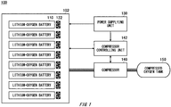
- Fig. 1 schematically shows an example of a battery system 100.
- the battery system 100 includes a lithium-oxygen battery 110, an enclosure case 102 enclosing the lithium-oxygen battery 110, a power supplying unit 130, a compressor 140, a compressor controlling unit 142, and a compressed oxygen tank 150.
- the enclosure case 102 encloses and contains oxygen and at least one lithium-oxygen battery 110.
- Fig. 1 shows an example in which the enclosure case 102 contains eight lithium-oxygen batteries 110.
- the lithium-oxygen battery 110 may be a battery in which oxygen is used as a positive electrode active material and lithium is used as a negative electrode active material.
- the lithium-oxygen battery 110 may be what is referred to as a lithium-air battery in which oxygen in the air is used as a positive electrode active material.
- lithium at the negative electrode dissolves, and lithium peroxide is deposited at the positive electrode side.
- lithium peroxide at the positive electrode decomposes, lithium is deposited on the negative electrode, and oxygen is released.
- the oxygen released from the lithium-oxygen battery 110 during the charging can be reused for the discharging.
- oxygen released from the lithium-oxygen battery 110 is stored in a compressed form. Then, in the battery system 100, the stored oxygen is supplied to the lithium-oxygen battery 110 for discharging the lithium-oxygen battery 110.
- Recycling oxygen contained in the enclosure case 102 in this manner enables efficient utilization of oxygen. Compared to the case of using oxygen in the air, it also enables supplying only oxygen to the lithium-oxygen battery 110 and improving the battery performance. Also, storing the compressed oxygen can significantly reduce the space for storage of oxygen as compared to the case without compressing the oxygen. This can realize miniaturization of the battery system 100. If the battery system 100 is installed in a moving body such as a car or airplane, the miniaturization of the battery system 100 contributes to miniaturization of the moving body, for example.
- the battery system 100 can achieve at least one of the following effects by recycling oxygen in the enclosure case 102: improving the battery performance; enabling its use e.g., even under low air pressure such as in the stratosphere; and yielding sufficient energy even in an environment with a limited space such as in a submarine, aircraft or car.
- an effect of providing a battery system with an increased ratio of power capacity to volume as compared to the conventional case is achieved.
- the power supplying unit 130 supplies electrical power to the lithium-oxygen battery 110 to charge the lithium-oxygen battery 110.
- the power supplying unit 130 may supply electrical power generated by means of any power generation system to the lithium-oxygen battery 110.
- the power supplying unit 130 supplies electrical power generated by solar power generation to the lithium-oxygen battery 110.
- the compressor 140 compresses oxygen released from the lithium-oxygen battery 110.
- the compressor 140 may compress oxygen released from the lithium-oxygen battery 110 as a result of the power supplying unit 130 charging the lithium-oxygen battery 110.
- the compressor 140 may be an example of the oxygen compressing unit.
- the compressor 140 may be connected to the enclosure case 102, and may compress oxygen contained in the enclosure case 102.
- the compressor 140 may be connected to the enclosure case 102 via a pipe.
- the compressor 140 may provide the compressed oxygen to be stored in the compressed oxygen tank 150.
- the compressed oxygen tank 150 may be an example of the storage unit.
- the compressor 140 may supply the oxygen stored in the compressed oxygen tank 150 to the lithium-oxygen battery 110.
- the compressor 140 may be an example of the oxygen supplying unit.
- the compressor 140 may be connected to the enclosure case 102, and may supply the oxygen stored in the compressed oxygen tank 150 to the enclosure case 102.
- the compressor controlling unit 142 controls the compressor 140.
- the compressor controlling unit 142 may use electrical power supplied from the power supplying unit 130 for causing the compressor 140 to compress oxygen or to supply oxygen stored in the compressed oxygen tank 150 to the lithium-oxygen battery 110.
- the compressor controlling unit 142 may also use electrical power provided by the lithium-oxygen battery 110 for causing the compressor 140 to compress oxygen or to supply oxygen stored in the compressed oxygen tank 150 to the lithium-oxygen battery 110.
- the compressor controlling unit 142 may cause the compressor 140 to generate electrical power by utilizing the expansive pressure of compressed oxygen stored in the compressed oxygen tank 150. That is, the compressor 140 may generate electrical power by utilizing the expansive pressure of compressed oxygen stored in the compressed oxygen tank 150.
- the compressor 140 may include a compressing/expanding unit and a driving/power-generating unit.
- the compressing/expanding unit compresses and expands oxygen.
- the driving/power-generating unit drives the compressing/expanding unit to compress oxygen.
- the compressor 140 is a displacement compressor
- the driving/power-generating unit drives a piston or screw rotor with a motor or the like to compress oxygen.
- the driving/power-generating unit expands compressed oxygen stored in the compressed oxygen tank 150 to generate electrical power by utilizing its expansive pressure.
- the compressor 140 is a displacement compressor
- the driving/power-generating unit converts force applied to the piston or screw rotor by the expansive pressure into electrical power.
- the driving/power-generating unit may generate electrical power by utilizing the expansive pressure in any other way.
- the compressor controlling unit 142 may supply electrical power generated by the compressor 140 to the lithium-oxygen battery 110 to charge the lithium-oxygen battery 110.
- the enclosure case 102 may include a blowing fan 122. As shown in Fig. 1 , the enclosure case 102 may include a plurality of blowing fans 122 corresponding to the plurality of respective lithium-oxygen batteries 110. Alternatively, the enclosure case 102 may include blowing fans 122 corresponding to the plurality of lithium-oxygen batteries 110 but fewer than the lithium-oxygen batteries 110.
- the blowing fan 122 may be disposed in the enclosure case 102 and blow oxygen supplied by the compressor 140 to the enclosure case 102 toward the lithium-oxygen battery 110.
- the blowing fan 122 may blow oxygen to reach the positive electrode of the lithium-oxygen battery 110.
- oxygen stored in the compressed oxygen tank 150 is supplied to the enclosure case 102 via the compressor 140, this is not limited.
- Oxygen stored in the compressed oxygen tank 150 may be supplied to the enclosure case 102 not via the compressor 140.
- the compressed oxygen tank 150 and the enclosure case 102 may be connected so that oxygen stored in the compressed oxygen tank 150 is directly supplied to the enclosure case 102.
- a valve may be disposed between the compressed oxygen tank 150 and the enclosure case 102 to control whether or not to supply the oxygen by opening or closing the valve.
- Fig. 2 schematically shows another example of the battery system 100.
- Fig. 2 illustrates a case in which the battery system 100 includes an internal pressure measuring unit 160, an internal pressure adjusting unit 162, a temperature measuring unit 170, a temperature adjusting unit 172, a heater 174, a blow rate adjusting unit 180, and an environment adjusting unit 190, in addition to the components described with reference to Fig. 1 .
- the battery system 100 may not include all of these components and may include only some of them.
- the internal pressure measuring unit 160 measures the internal pressure of the enclosure case 102.
- the internal pressure measuring unit 160 is any pressure sensor disposed in the enclosure case 102 to measure the air pressure in the enclosure case 102.
- the internal pressure adjusting unit 162 adjusts the internal pressure of the enclosure case 102.
- the internal pressure adjusting unit 162 may maintain the internal pressure of the enclosure case 102 within a predetermined range.
- the predetermined range may be experimentally determined. For example, an experiment may be performed for measuring variation in performance of the lithium-oxygen battery 110 while varying the internal pressure of the enclosure case 102, and a range of the internal pressure of the enclosure case 102 in which the performance of the lithium-oxygen battery 110 exceeds a threshold may be determined as the predetermined range.
- the internal pressure adjusting unit 162 may cause the compressor 140 to compress oxygen contained in the enclosure case 102 if the internal pressure of the enclosure case 102 measured by the internal pressure measuring unit 160 is higher than the predetermined threshold.
- the internal pressure adjusting unit 162 may cause the compressor 140 to supply oxygen stored in the compressed oxygen tank 150 to the enclosure case 102 if the internal pressure of the enclosure case 102 measured by the internal pressure measuring unit 160 is lower than the predetermined threshold.
- the internal pressure adjusting unit 162 may adjust the internal pressure of the enclosure case 102 by adjusting the rotation rate of the compressor 140. For example, the internal pressure adjusting unit 162 increases the rotation rate of the compressor 140 to lower the internal pressure of the enclosure case 102.
- the battery system 100 may further include a valve to adjust the amount of supplying oxygen stored in the compressed oxygen tank 150 to the enclosure case 102, and the internal pressure adjusting unit 162 may adjust the internal pressure of the enclosure case 102 by controlling the valve.
- the internal pressure measuring unit 160 and the internal pressure adjusting unit 162 may use electrical power provided by the lithium-oxygen battery 110.
- the internal pressure measuring unit 160 and the internal pressure adjusting unit 162 may also use electrical power supplied by the power supplying unit 130.
- the temperature measuring unit 170 measures the temperature in the enclosure case 102.
- the temperature measuring unit 170 is any temperature sensor disposed in the enclosure case 102 to measure the temperature in the enclosure case 102.
- the temperature adjusting unit 172 adjusts the temperature in the enclosure case 102.
- the temperature adjusting unit 172 may maintain the temperature in the enclosure case 102 within a predetermined range.
- the predetermined range may be experimentally determined. For example, an experiment may be performed for measuring variation in performance of the lithium-oxygen battery 110 while varying the temperature in the enclosure case 102, and a range of the temperature in the enclosure case 102 in which the performance of the lithium-oxygen battery 110 exceeds a threshold may be determined as the predetermined range.
- the temperature adjusting unit 172 may adjust the temperature in the enclosure case 102 by heating oxygen supplied from the compressor 140 to the enclosure case 102 using the heater 174, which is provided to a pipe connecting the enclosure case 102 and the compressor 140.
- the temperature adjusting unit 172 may adjust the temperature in the enclosure case 102 by heating inside the enclosure case 102 using a heater, which is not shown in the figure, provided in the enclosure case 102.
- the enclosure case 102 may be formed of any material capable of maintaining the internal pressure. Also, the enclosure case 102 may have a heat retaining property.
- the enclosure case 102 may include a thermal insulation material.
- the thermal insulation material may be a fiber-based thermal insulation material, foam-based thermal insulation material, vacuum thermal insulation material, etc. Specific examples of the fiber-based thermal insulation material include glass wool, rock wool, cellulose fiber, carbonized cork, wool thermal insulation material, etc.
- Specific examples of the foam-based thermal insulation material include urethane foam, phenolic foam, polystyrene foam, expanded polystyrene foam (EPS), extruded polystyrene foam (XPS), foamed rubber, etc.
- the temperature adjusting unit 172 may adjust the temperature in the enclosure case 102 by cooling oxygen supplied from the compressor 140 to the enclosure case 102 or the inside of the enclosure case 102.
- the temperature adjusting unit 172 adjusts the temperature in the enclosure case 102 by cooling oxygen supplied from the compressor 140 to the enclosure case 102 using a Peltier device or the like, which is not shown in the figure, provided to a pipe connecting the enclosure case 102 and the compressor 140, or by cooling inside the enclosure case 102 using a Peltier device or the like provided in the enclosure case 102.
- the temperature adjusting unit 172 may adjust the temperature in the enclosure case 102 by controlling the heating and cooling of oxygen supplied from the compressor 140 to the enclosure case 102 or the inside of the enclosure case 102.
- the compressor controlling unit 142 may control the compressor 140 according to the operating mode of the battery system 100.
- Operating modes may include a normal mode, a powered mode with a larger amount of electrical power supply than in the normal mode, an eco-mode with a smaller amount of electrical power supply than the normal mode, etc.
- Operating modes may include only two modes with different amounts of electrical power supply, or may include four or more modes.
- the compressor controlling unit 142 increases the amount of supplying oxygen stored in the compressed oxygen tank 150 to the enclosure case 102.
- the compressor controlling unit 142 may reduce the amount of supplying oxygen stored in the compressed oxygen tank 150 to the enclosure case 102.
- the compressor controlling unit 142 may adjust the amount of supplying oxygen stored in the compressed oxygen tank 150 to the enclosure case 102 by controlling the rotation rate of the compressor 140 and a valve to adjust the supply amount.
- the environment adjusting unit 190 adjusts the environment of the lithium-oxygen battery 110.
- the environment adjusting unit 190 may adjust the environment of the lithium-oxygen battery 110 by controlling at least one of: the internal pressure of the enclosure case 102; the temperature in the enclosure case 102; and the blow rate of the blowing fan 122.
- the environment adjusting unit 190 may adjust the environment of the lithium-oxygen battery 110 according to the operating mode of the battery system 100. For example, when the powered mode is selected, the environment adjusting unit 190 causes the internal pressure adjusting unit 162 to raise the internal pressure of the enclosure case 102, causes the temperature adjusting unit 172 to raise the temperature in the enclosure case 102, or causes the blow rate adjusting unit 180 to increase the blow rate of the blowing fan 122, in order to increase the amount of electricity discharged by the lithium-oxygen battery 110.
- the environment adjusting unit 190 may perform only one of the three operations, or may perform two or more of them.
- the environment adjusting unit 190 causes the internal pressure adjusting unit 162 to lower the internal pressure of the enclosure case 102, causes the temperature adjusting unit 172 to lower the temperature in the enclosure case 102, or causes the blow rate adjusting unit 180 to reduce the blow rate of the blowing fan 122, in order to decrease the amount of electricity discharged by the lithium-oxygen battery 110.
- the environment adjusting unit 190 may perform only one of the three operations, or may perform two or more of them.
- the environment adjusting unit 190 may increase the amount of electricity discharged by the lithium-oxygen battery 110 by collectively controlling the internal pressure of the enclosure case 102, the temperature in the enclosure case 102, and the blow rate of the blowing fan 122. That is, the environment adjusting unit 190 may increase the amount of electricity discharged by the lithium-oxygen battery 110 by performing any combination of: raising or lowering the internal pressure of the enclosure case 102; raising or lowering the temperature in the enclosure case 102; and increasing or reducing the blow rate of the blowing fan 122.
- the environment adjusting unit 190 may reduce the amount of electricity discharged by the lithium-oxygen battery 110 by collectively controlling the internal pressure of the enclosure case 102, the temperature in the enclosure case 102, and the blow rate of the blowing fan 122. That is, the environment adjusting unit 190 may decrease the amount of electricity discharged by the lithium-oxygen battery 110 by performing any combination of: raising or lowering the internal pressure of the enclosure case 102; raising or lowering the temperature in the enclosure case 102; and increasing or reducing the blow rate of the blowing fan 122.
- Fig. 3 schematically shows an example of the lithium-oxygen battery 110.
- the lithium-oxygen battery 110 shown in Fig. 3 includes a porous current collector 113, a porous carbon positive electrode 114, a separator 116, and a lithium metal negative electrode 118, which are covered by a package 111.
- Porous carbon positive electrodes 114 are disposed on both sides of a porous current collector 113, which is formed of an oxygen-intaking material, and a separator 116 and a lithium metal negative electrode 118 are disposed in parallel, to form a stack.
- Oxygen in the enclosure case 102 is supplied to the stack via a vent hole 112 formed in the package 111, and the oxygen is supplied to the porous carbon positive electrode 114 via the porous current collector 113, so that a discharge reaction occurs.
- the blowing fan 122 may blow oxygen toward the vent hole 112. This can increase the probability of adsorbing oxygen to the porous carbon positive electrode 114.
- the constitution of the lithium-oxygen battery 110 shown in Fig. 3 is an example, and the lithium-oxygen battery 110 may have another constitution.
- the lithium-oxygen battery 110 does not have a stacked structure, and includes a pair of porous carbon positive electrodes 114, a separator 116 and a lithium metal negative electrode 118.
- the lithium-oxygen battery 110 may also have a stacked structure different from the constitution shown in Fig. 3 .
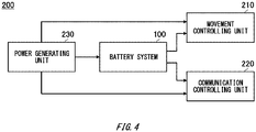
- Fig. 4 schematically shows an example of a moving body 200.
- the moving body 200 includes the battery system 100, a movement controlling unit 210, a communication controlling unit 220, and a power generating unit 230.
- the moving body 200 does not necessarily include all of these components.
- the movement controlling unit 210 performs movement control of the moving body 200 using electrical power of the lithium-oxygen battery 110. If the moving body 200 is a vehicle such as a motor vehicle, the movement controlling unit 210 controls the driving of the moving body 200. For example, the battery system 100 may be used as a battery for an electric motor vehicle. If the moving body 200 is a flying body, the movement controlling unit 210 controls the flight of the moving body 200.
- the communication controlling unit 220 performs wireless communication using electrical power of the lithium-oxygen battery 110.
- the communication controlling unit 220 provides a wireless communication service for a wireless communication terminal such as a mobile phone by relaying the wireless communication terminal and a core network.
- the moving body 200 is a vehicle such as a motor vehicle, the moving body 200 may serve as a mobile base station vehicle. Also, for example, if the moving body 200 is a flying body, the moving body 200 may serve as a stratospheric platform.
- the power generating unit 230 generates electrical power.
- the power generating unit 230 generates electrical power by solar power generation.
- the power generating unit 230 may supply the generated electrical power to the power supplying unit 130 of the battery system 100.
- the power supplying unit 130 may supply the electrical power received from the power generating unit 230 to the lithium-oxygen battery 110, the compressor controlling unit 142, etc.
- the power generating unit 230 may supply the generated electrical power to the movement controlling unit 210.
- the power generating unit 230 may also supply the generated electrical power to the communication controlling unit 220.
- 100 battery system, 102: enclosure case, 110: lithium-oxygen battery, 111: package, 112: vent hole, 113: porous current collector, 114: porous carbon positive electrode, 116: separator, 118: lithium metal negative electrode, 122: blowing fan, 130: power supplying unit, 140: compressor, 142: compressor controlling unit, 150: compressed oxygen tank, 160: internal pressure measuring unit, 162: internal pressure adjusting unit, 170: temperature measuring unit, 172: temperature adjusting unit, 174: heater, 180: blow rate adjusting unit, 190: environment adjusting unit, 200: moving body, 210: movement controlling unit, 220: communication controlling unit, 230: power generating unit
Landscapes
- Engineering & Computer Science (AREA)
- Chemical & Material Sciences (AREA)
- Chemical Kinetics & Catalysis (AREA)
- Electrochemistry (AREA)
- General Chemical & Material Sciences (AREA)
- Manufacturing & Machinery (AREA)
- Life Sciences & Earth Sciences (AREA)
- Sustainable Development (AREA)
- Sustainable Energy (AREA)
- Transportation (AREA)
- Power Engineering (AREA)
- Mechanical Engineering (AREA)
- Physics & Mathematics (AREA)
- Electromagnetism (AREA)
- Aviation & Aerospace Engineering (AREA)
- Automation & Control Theory (AREA)
- Microelectronics & Electronic Packaging (AREA)
- Materials Engineering (AREA)
- Hybrid Cells (AREA)
- Secondary Cells (AREA)
Abstract
Description
- The present invention relates to a battery system and a moving body.
- Lithium-air batteries have been known, in which oxygen in the air is used as a positive electrode active material and lithium is used as a negative electrode active material (see Patent Document 1, for example).
- Patent Document 1: International Publication
WO 2015/115480 - It is desired to provide a battery system capable of efficient utilization of oxygen.
- A first aspect of the present invention provides a battery system. The battery system may include a lithium-oxygen battery. The battery system may include an oxygen compressing unit configured to compress oxygen released from the lithium-oxygen battery. The battery system may include a storage unit configured to store oxygen compressed by the oxygen compressing unit. The battery system may include an oxygen supplying unit configured to supply oxygen stored in the storage unit to the lithium-oxygen battery.
- The battery system may further include an enclosure case enclosing the lithium-oxygen battery, and the oxygen compressing unit and the oxygen supplying unit may be connected to the enclosure case. The oxygen supplying unit may supply oxygen stored in the storage unit to the enclosure case, and the battery system may further include a blowing fan disposed in the enclosure case and configured to blow oxygen supplied by the oxygen supplying unit toward the lithium-oxygen battery.
- The battery system may further include an internal pressure measuring unit configured to measure an internal pressure of the enclosure case; and an internal pressure adjusting unit configured to maintain the internal pressure of the enclosure case within a predetermined range. The internal pressure adjusting unit may cause the oxygen compressing unit to compress oxygen contained in the enclosure case if the internal pressure of the enclosure case is higher than a predetermined threshold, and may cause the oxygen supplying unit to supply oxygen stored in the storage unit to the enclosure case if the internal pressure of the enclosure case is lower than the predetermined threshold. The oxygen supplying unit may be a compressor, and the internal pressure adjusting unit may maintain the internal pressure of the enclosure case by adjusting a rotation rate of the compressor. The internal pressure adjusting unit may maintain the internal pressure of the enclosure case by controlling a valve to adjust an amount of supplying oxygen stored in the storage unit to the enclosure case.
- The battery system may further include a temperature measuring unit configured to measure a temperature in the enclosure case; and a temperature adjusting unit configured to maintain the temperature in the enclosure case within a predetermined range. The temperature adjusting unit may adjust the temperature in the enclosure case by heating oxygen supplied from the oxygen supplying unit to the enclosure case. The temperature adjusting unit may adjust the temperature in the enclosure case by heating inside the enclosure case with a heater provided in the enclosure case. The enclosure case may have a heat retaining property. The enclosure case may include a thermal insulation material.
- The oxygen compressing unit may be a compressor. The oxygen supplying unit may be the compressor. The compressor may compress oxygen using electrical power of the lithium-oxygen battery. The compressor may generate electrical power by utilizing expansive pressure of compressed oxygen stored in the storage unit.
- The battery system may include a power supplying unit configured to supply electrical power to the lithium-oxygen battery to charge the lithium-oxygen battery, and the oxygen compressing unit may compress oxygen released from the lithium-oxygen battery as a result of the power supplying unit charging the lithium-oxygen battery. The power supplying unit may supply electrical power generated by solar power generation to the lithium-oxygen battery.
- A second aspect of the present invention provides a moving body including: the battery system; and a movement controlling unit configured to perform movement control using electrical power of the lithium-oxygen battery.
- A third aspect of the present invention provides a moving body including: the battery system; and a wireless communication unit configured to perform wireless communication using electrical power of the lithium-oxygen battery.
- A fourth aspect of the present invention provides the the moving body that is capable of flying and serves as a stratospheric platform.
- The summary clause does not necessarily describe all necessary features of the embodiments of the present invention. The present invention may also be a sub-combination of the features described above.
-
-
Fig. 1 schematically shows an example of abattery system 100. -
Fig. 2 schematically shows another example of thebattery system 100. -
Fig. 3 schematically shows an example of a lithium-oxygen battery 110. -
Fig. 4 schematically shows an example of a movingbody 200. - Hereinafter, (some) embodiment(s) of the present invention will be described. The embodiment(s) do(es) not limit the invention according to the claims, and all the combinations of the features described in the embodiment(s) are not necessarily essential to means provided by aspects of the invention.
-
Fig. 1 schematically shows an example of abattery system 100. Thebattery system 100 includes a lithium-oxygen battery 110, anenclosure case 102 enclosing the lithium-oxygen battery 110, apower supplying unit 130, acompressor 140, acompressor controlling unit 142, and acompressed oxygen tank 150. - The
enclosure case 102 encloses and contains oxygen and at least one lithium-oxygen battery 110.Fig. 1 shows an example in which theenclosure case 102 contains eight lithium-oxygen batteries 110. - The lithium-
oxygen battery 110 may be a battery in which oxygen is used as a positive electrode active material and lithium is used as a negative electrode active material. The lithium-oxygen battery 110 may be what is referred to as a lithium-air battery in which oxygen in the air is used as a positive electrode active material. - During the discharging of the lithium-
oxygen battery 110, lithium at the negative electrode dissolves, and lithium peroxide is deposited at the positive electrode side. During the charging of the lithium-oxygen battery 110, lithium peroxide at the positive electrode decomposes, lithium is deposited on the negative electrode, and oxygen is released. - Desirably, the oxygen released from the lithium-
oxygen battery 110 during the charging can be reused for the discharging. In thebattery system 100 according to the present embodiment, oxygen released from the lithium-oxygen battery 110 is stored in a compressed form. Then, in thebattery system 100, the stored oxygen is supplied to the lithium-oxygen battery 110 for discharging the lithium-oxygen battery 110. - Recycling oxygen contained in the
enclosure case 102 in this manner enables efficient utilization of oxygen. Compared to the case of using oxygen in the air, it also enables supplying only oxygen to the lithium-oxygen battery 110 and improving the battery performance. Also, storing the compressed oxygen can significantly reduce the space for storage of oxygen as compared to the case without compressing the oxygen. This can realize miniaturization of thebattery system 100. If thebattery system 100 is installed in a moving body such as a car or airplane, the miniaturization of thebattery system 100 contributes to miniaturization of the moving body, for example. - As described above, compared to the conventional case of using oxygen in the environmental air for the discharging and releasing the oxygen into the air during the charging, the
battery system 100 according to the present embodiment can achieve at least one of the following effects by recycling oxygen in the enclosure case 102: improving the battery performance; enabling its use e.g., even under low air pressure such as in the stratosphere; and yielding sufficient energy even in an environment with a limited space such as in a submarine, aircraft or car. Thus, an effect of providing a battery system with an increased ratio of power capacity to volume as compared to the conventional case is achieved. - The
power supplying unit 130 supplies electrical power to the lithium-oxygen battery 110 to charge the lithium-oxygen battery 110. Thepower supplying unit 130 may supply electrical power generated by means of any power generation system to the lithium-oxygen battery 110. For example, thepower supplying unit 130 supplies electrical power generated by solar power generation to the lithium-oxygen battery 110. - The
compressor 140 compresses oxygen released from the lithium-oxygen battery 110. Thecompressor 140 may compress oxygen released from the lithium-oxygen battery 110 as a result of thepower supplying unit 130 charging the lithium-oxygen battery 110. Thecompressor 140 may be an example of the oxygen compressing unit. - The
compressor 140 may be connected to theenclosure case 102, and may compress oxygen contained in theenclosure case 102. Thecompressor 140 may be connected to theenclosure case 102 via a pipe. Thecompressor 140 may provide the compressed oxygen to be stored in thecompressed oxygen tank 150. Thecompressed oxygen tank 150 may be an example of the storage unit. - The
compressor 140 may supply the oxygen stored in thecompressed oxygen tank 150 to the lithium-oxygen battery 110. Thecompressor 140 may be an example of the oxygen supplying unit. Thecompressor 140 may be connected to theenclosure case 102, and may supply the oxygen stored in thecompressed oxygen tank 150 to theenclosure case 102. - The
compressor controlling unit 142 controls thecompressor 140. Thecompressor controlling unit 142 may use electrical power supplied from thepower supplying unit 130 for causing thecompressor 140 to compress oxygen or to supply oxygen stored in thecompressed oxygen tank 150 to the lithium-oxygen battery 110. Thecompressor controlling unit 142 may also use electrical power provided by the lithium-oxygen battery 110 for causing thecompressor 140 to compress oxygen or to supply oxygen stored in thecompressed oxygen tank 150 to the lithium-oxygen battery 110. - The
compressor controlling unit 142 may cause thecompressor 140 to generate electrical power by utilizing the expansive pressure of compressed oxygen stored in thecompressed oxygen tank 150. That is, thecompressor 140 may generate electrical power by utilizing the expansive pressure of compressed oxygen stored in thecompressed oxygen tank 150. - The
compressor 140 may include a compressing/expanding unit and a driving/power-generating unit. The compressing/expanding unit compresses and expands oxygen. The driving/power-generating unit drives the compressing/expanding unit to compress oxygen. For example, if thecompressor 140 is a displacement compressor, the driving/power-generating unit drives a piston or screw rotor with a motor or the like to compress oxygen. Also, the driving/power-generating unit expands compressed oxygen stored in thecompressed oxygen tank 150 to generate electrical power by utilizing its expansive pressure. For example, if thecompressor 140 is a displacement compressor, the driving/power-generating unit converts force applied to the piston or screw rotor by the expansive pressure into electrical power. The driving/power-generating unit may generate electrical power by utilizing the expansive pressure in any other way. Thecompressor controlling unit 142 may supply electrical power generated by thecompressor 140 to the lithium-oxygen battery 110 to charge the lithium-oxygen battery 110. - As shown in
Fig. 1 , theenclosure case 102 may include a blowingfan 122. As shown inFig. 1 , theenclosure case 102 may include a plurality of blowingfans 122 corresponding to the plurality of respective lithium-oxygen batteries 110. Alternatively, theenclosure case 102 may include blowingfans 122 corresponding to the plurality of lithium-oxygen batteries 110 but fewer than the lithium-oxygen batteries 110. - The blowing
fan 122 may be disposed in theenclosure case 102 and blow oxygen supplied by thecompressor 140 to theenclosure case 102 toward the lithium-oxygen battery 110. The blowingfan 122 may blow oxygen to reach the positive electrode of the lithium-oxygen battery 110. - While in the example of
Fig. 1 , oxygen stored in thecompressed oxygen tank 150 is supplied to theenclosure case 102 via thecompressor 140, this is not limited. Oxygen stored in thecompressed oxygen tank 150 may be supplied to theenclosure case 102 not via thecompressor 140. For example, thecompressed oxygen tank 150 and theenclosure case 102 may be connected so that oxygen stored in thecompressed oxygen tank 150 is directly supplied to theenclosure case 102. In this case, for example, a valve may be disposed between thecompressed oxygen tank 150 and theenclosure case 102 to control whether or not to supply the oxygen by opening or closing the valve. -
Fig. 2 schematically shows another example of thebattery system 100.Fig. 2 illustrates a case in which thebattery system 100 includes an internalpressure measuring unit 160, an internalpressure adjusting unit 162, atemperature measuring unit 170, atemperature adjusting unit 172, aheater 174, a blowrate adjusting unit 180, and anenvironment adjusting unit 190, in addition to the components described with reference toFig. 1 . Note that thebattery system 100 may not include all of these components and may include only some of them. - The internal
pressure measuring unit 160 measures the internal pressure of theenclosure case 102. For example, the internalpressure measuring unit 160 is any pressure sensor disposed in theenclosure case 102 to measure the air pressure in theenclosure case 102. - The internal
pressure adjusting unit 162 adjusts the internal pressure of theenclosure case 102. The internalpressure adjusting unit 162 may maintain the internal pressure of theenclosure case 102 within a predetermined range. The predetermined range may be experimentally determined. For example, an experiment may be performed for measuring variation in performance of the lithium-oxygen battery 110 while varying the internal pressure of theenclosure case 102, and a range of the internal pressure of theenclosure case 102 in which the performance of the lithium-oxygen battery 110 exceeds a threshold may be determined as the predetermined range. - The internal
pressure adjusting unit 162 may cause thecompressor 140 to compress oxygen contained in theenclosure case 102 if the internal pressure of theenclosure case 102 measured by the internalpressure measuring unit 160 is higher than the predetermined threshold. The internalpressure adjusting unit 162 may cause thecompressor 140 to supply oxygen stored in thecompressed oxygen tank 150 to theenclosure case 102 if the internal pressure of theenclosure case 102 measured by the internalpressure measuring unit 160 is lower than the predetermined threshold. - The internal
pressure adjusting unit 162 may adjust the internal pressure of theenclosure case 102 by adjusting the rotation rate of thecompressor 140. For example, the internalpressure adjusting unit 162 increases the rotation rate of thecompressor 140 to lower the internal pressure of theenclosure case 102. - The
battery system 100 may further include a valve to adjust the amount of supplying oxygen stored in thecompressed oxygen tank 150 to theenclosure case 102, and the internalpressure adjusting unit 162 may adjust the internal pressure of theenclosure case 102 by controlling the valve. - The internal
pressure measuring unit 160 and the internalpressure adjusting unit 162 may use electrical power provided by the lithium-oxygen battery 110. The internalpressure measuring unit 160 and the internalpressure adjusting unit 162 may also use electrical power supplied by thepower supplying unit 130. - The
temperature measuring unit 170 measures the temperature in theenclosure case 102. For example, thetemperature measuring unit 170 is any temperature sensor disposed in theenclosure case 102 to measure the temperature in theenclosure case 102. - The
temperature adjusting unit 172 adjusts the temperature in theenclosure case 102. Thetemperature adjusting unit 172 may maintain the temperature in theenclosure case 102 within a predetermined range. The predetermined range may be experimentally determined. For example, an experiment may be performed for measuring variation in performance of the lithium-oxygen battery 110 while varying the temperature in theenclosure case 102, and a range of the temperature in theenclosure case 102 in which the performance of the lithium-oxygen battery 110 exceeds a threshold may be determined as the predetermined range. - The
temperature adjusting unit 172 may adjust the temperature in theenclosure case 102 by heating oxygen supplied from thecompressor 140 to theenclosure case 102 using theheater 174, which is provided to a pipe connecting theenclosure case 102 and thecompressor 140. - The
temperature adjusting unit 172 may adjust the temperature in theenclosure case 102 by heating inside theenclosure case 102 using a heater, which is not shown in the figure, provided in theenclosure case 102. - The
enclosure case 102 may be formed of any material capable of maintaining the internal pressure. Also, theenclosure case 102 may have a heat retaining property. Theenclosure case 102 may include a thermal insulation material. The thermal insulation material may be a fiber-based thermal insulation material, foam-based thermal insulation material, vacuum thermal insulation material, etc. Specific examples of the fiber-based thermal insulation material include glass wool, rock wool, cellulose fiber, carbonized cork, wool thermal insulation material, etc. Specific examples of the foam-based thermal insulation material include urethane foam, phenolic foam, polystyrene foam, expanded polystyrene foam (EPS), extruded polystyrene foam (XPS), foamed rubber, etc. - While the use of a heater is described in the present example, this is not limited. The
temperature adjusting unit 172 may adjust the temperature in theenclosure case 102 by cooling oxygen supplied from thecompressor 140 to theenclosure case 102 or the inside of theenclosure case 102. For example, thetemperature adjusting unit 172 adjusts the temperature in theenclosure case 102 by cooling oxygen supplied from thecompressor 140 to theenclosure case 102 using a Peltier device or the like, which is not shown in the figure, provided to a pipe connecting theenclosure case 102 and thecompressor 140, or by cooling inside theenclosure case 102 using a Peltier device or the like provided in theenclosure case 102. Thetemperature adjusting unit 172 may adjust the temperature in theenclosure case 102 by controlling the heating and cooling of oxygen supplied from thecompressor 140 to theenclosure case 102 or the inside of theenclosure case 102. - The
compressor controlling unit 142 may control thecompressor 140 according to the operating mode of thebattery system 100. Operating modes may include a normal mode, a powered mode with a larger amount of electrical power supply than in the normal mode, an eco-mode with a smaller amount of electrical power supply than the normal mode, etc. Operating modes may include only two modes with different amounts of electrical power supply, or may include four or more modes. - For example, when the powered mode is selected, the
compressor controlling unit 142 increases the amount of supplying oxygen stored in thecompressed oxygen tank 150 to theenclosure case 102. When the eco-mode is selected, thecompressor controlling unit 142 may reduce the amount of supplying oxygen stored in thecompressed oxygen tank 150 to theenclosure case 102. For example, thecompressor controlling unit 142 may adjust the amount of supplying oxygen stored in thecompressed oxygen tank 150 to theenclosure case 102 by controlling the rotation rate of thecompressor 140 and a valve to adjust the supply amount. - The
environment adjusting unit 190 adjusts the environment of the lithium-oxygen battery 110. Theenvironment adjusting unit 190 may adjust the environment of the lithium-oxygen battery 110 by controlling at least one of: the internal pressure of theenclosure case 102; the temperature in theenclosure case 102; and the blow rate of the blowingfan 122. - The
environment adjusting unit 190 may adjust the environment of the lithium-oxygen battery 110 according to the operating mode of thebattery system 100. For example, when the powered mode is selected, theenvironment adjusting unit 190 causes the internalpressure adjusting unit 162 to raise the internal pressure of theenclosure case 102, causes thetemperature adjusting unit 172 to raise the temperature in theenclosure case 102, or causes the blowrate adjusting unit 180 to increase the blow rate of the blowingfan 122, in order to increase the amount of electricity discharged by the lithium-oxygen battery 110. Theenvironment adjusting unit 190 may perform only one of the three operations, or may perform two or more of them. - For example, when the eco-mode is selected, the
environment adjusting unit 190 causes the internalpressure adjusting unit 162 to lower the internal pressure of theenclosure case 102, causes thetemperature adjusting unit 172 to lower the temperature in theenclosure case 102, or causes the blowrate adjusting unit 180 to reduce the blow rate of the blowingfan 122, in order to decrease the amount of electricity discharged by the lithium-oxygen battery 110. Theenvironment adjusting unit 190 may perform only one of the three operations, or may perform two or more of them. - When the powered mode is selected, the
environment adjusting unit 190 may increase the amount of electricity discharged by the lithium-oxygen battery 110 by collectively controlling the internal pressure of theenclosure case 102, the temperature in theenclosure case 102, and the blow rate of the blowingfan 122. That is, theenvironment adjusting unit 190 may increase the amount of electricity discharged by the lithium-oxygen battery 110 by performing any combination of: raising or lowering the internal pressure of theenclosure case 102; raising or lowering the temperature in theenclosure case 102; and increasing or reducing the blow rate of the blowingfan 122. - When the eco-mode is selected, the
environment adjusting unit 190 may reduce the amount of electricity discharged by the lithium-oxygen battery 110 by collectively controlling the internal pressure of theenclosure case 102, the temperature in theenclosure case 102, and the blow rate of the blowingfan 122. That is, theenvironment adjusting unit 190 may decrease the amount of electricity discharged by the lithium-oxygen battery 110 by performing any combination of: raising or lowering the internal pressure of theenclosure case 102; raising or lowering the temperature in theenclosure case 102; and increasing or reducing the blow rate of the blowingfan 122. -
Fig. 3 schematically shows an example of the lithium-oxygen battery 110. The lithium-oxygen battery 110 shown inFig. 3 includes a porouscurrent collector 113, a porous carbonpositive electrode 114, aseparator 116, and a lithium metalnegative electrode 118, which are covered by apackage 111. Porous carbonpositive electrodes 114 are disposed on both sides of a porouscurrent collector 113, which is formed of an oxygen-intaking material, and aseparator 116 and a lithium metalnegative electrode 118 are disposed in parallel, to form a stack. Oxygen in theenclosure case 102 is supplied to the stack via avent hole 112 formed in thepackage 111, and the oxygen is supplied to the porous carbonpositive electrode 114 via the porouscurrent collector 113, so that a discharge reaction occurs. - The blowing
fan 122 may blow oxygen toward thevent hole 112. This can increase the probability of adsorbing oxygen to the porous carbonpositive electrode 114. - Note that the constitution of the lithium-
oxygen battery 110 shown inFig. 3 is an example, and the lithium-oxygen battery 110 may have another constitution. For example, the lithium-oxygen battery 110 does not have a stacked structure, and includes a pair of porous carbonpositive electrodes 114, aseparator 116 and a lithium metalnegative electrode 118. The lithium-oxygen battery 110 may also have a stacked structure different from the constitution shown inFig. 3 . -
Fig. 4 schematically shows an example of a movingbody 200. The movingbody 200 includes thebattery system 100, amovement controlling unit 210, acommunication controlling unit 220, and apower generating unit 230. The movingbody 200 does not necessarily include all of these components. - The
movement controlling unit 210 performs movement control of the movingbody 200 using electrical power of the lithium-oxygen battery 110. If the movingbody 200 is a vehicle such as a motor vehicle, themovement controlling unit 210 controls the driving of the movingbody 200. For example, thebattery system 100 may be used as a battery for an electric motor vehicle. If the movingbody 200 is a flying body, themovement controlling unit 210 controls the flight of the movingbody 200. - The
communication controlling unit 220 performs wireless communication using electrical power of the lithium-oxygen battery 110. For example, thecommunication controlling unit 220 provides a wireless communication service for a wireless communication terminal such as a mobile phone by relaying the wireless communication terminal and a core network. For example, if the movingbody 200 is a vehicle such as a motor vehicle, the movingbody 200 may serve as a mobile base station vehicle. Also, for example, if the movingbody 200 is a flying body, the movingbody 200 may serve as a stratospheric platform. - The
power generating unit 230 generates electrical power. For example, thepower generating unit 230 generates electrical power by solar power generation. Thepower generating unit 230 may supply the generated electrical power to thepower supplying unit 130 of thebattery system 100. Thepower supplying unit 130 may supply the electrical power received from thepower generating unit 230 to the lithium-oxygen battery 110, thecompressor controlling unit 142, etc. - The
power generating unit 230 may supply the generated electrical power to themovement controlling unit 210. Thepower generating unit 230 may also supply the generated electrical power to thecommunication controlling unit 220. - While the embodiments of the present invention have been described, the technical scope of the invention is not limited to the above described embodiments. It is apparent to persons skilled in the art that various alterations and improvements can be added to the above-described embodiments. It is also apparent from the scope of the claims that the embodiments added with such alterations or improvements can be included in the technical scope of the invention.
- 100: battery system, 102: enclosure case, 110: lithium-oxygen battery, 111: package, 112: vent hole, 113: porous current collector, 114: porous carbon positive electrode, 116: separator, 118: lithium metal negative electrode, 122: blowing fan, 130: power supplying unit, 140: compressor, 142: compressor controlling unit, 150: compressed oxygen tank, 160: internal pressure measuring unit, 162: internal pressure adjusting unit, 170: temperature measuring unit, 172: temperature adjusting unit, 174: heater, 180: blow rate adjusting unit, 190: environment adjusting unit, 200: moving body, 210: movement controlling unit, 220: communication controlling unit, 230: power generating unit
Claims (24)
- A battery system comprising:a lithium-oxygen battery;an oxygen compressing unit configured to compress oxygen released from the lithium-oxygen battery;a storage unit configured to store oxygen compressed by the oxygen compressing unit; andan oxygen supplying unit configured to supply oxygen stored in the storage unit to the lithium-oxygen battery.
- The battery system according to claim 1,
further comprising an enclosure case enclosing the lithium-oxygen battery, wherein
the oxygen compressing unit and the oxygen supplying unit are connected to the enclosure case. - The battery system according to claim 2, wherein
the oxygen supplying unit supplies oxygen stored in the storage unit to the enclosure case, and
the battery system further comprises a blowing fan disposed in the enclosure case and configured to blow oxygen supplied by the oxygen supplying unit toward the lithium-oxygen battery. - The battery system according to claim 2 or 3, comprising:an internal pressure measuring unit configured to measure an internal pressure of the enclosure case; andan internal pressure adjusting unit configured to maintain the internal pressure of the enclosure case within a predetermined range.
- The battery system according to claim 4, wherein the internal pressure adjusting unit causes the oxygen compressing unit to compress oxygen contained in the enclosure case if the internal pressure of the enclosure case is higher than a predetermined threshold, and causes the oxygen supplying unit to supply oxygen stored in the storage unit to the enclosure case if the internal pressure of the enclosure case is lower than the predetermined threshold.
- The battery system according to claim 4 or 5, wherein
the oxygen supplying unit is a compressor, and
the internal pressure adjusting unit maintains the internal pressure of the enclosure case by adjusting a rotation rate of the compressor. - The battery system according to claim 4 or 5, wherein the internal pressure adjusting unit maintains the internal pressure of the enclosure case by controlling a valve to adjust an amount of supplying oxygen stored in the storage unit to the enclosure case.
- The battery system according to any one of claims 2 to 7, comprising:a temperature measuring unit configured to measure a temperature in the enclosure case; anda temperature adjusting unit configured to maintain the temperature in the enclosure case within a predetermined range.
- The battery system according to claim 8, wherein the temperature adjusting unit adjusts the temperature in the enclosure case by heating oxygen supplied from the oxygen supplying unit to the enclosure case.
- The battery system according to claim 8, wherein the temperature adjusting unit adjusts the temperature in the enclosure case by heating inside the enclosure case with a heater provided in the enclosure case.
- The battery system according to any one of claims 2 to 10, wherein the enclosure case has a heat retaining property.
- The battery system according to claim 11, wherein the enclosure case comprises a thermal insulation material.
- The battery system according to claim 3, further comprising:a blow rate adjusting unit configured to adjust a blow rate of the blowing fan;an internal pressure measuring unit configured to measure an internal pressure of the enclosure case;an internal pressure adjusting unit configured to adjust the internal pressure of the enclosure case;a temperature measuring unit configured to measure a temperature in the enclosure case; anda temperature adjusting unit configured to adjust the temperature in the enclosure case.
- The battery system according to claim 13, further comprising an environment adjusting unit configured to adjust an environment of the lithium-oxygen battery by controlling at least one of: adjustment of the blow rate performed by the blow rate adjusting unit; adjustment of the internal pressure of the enclosure case performed by the internal pressure adjusting unit; and adjustment of the temperature in the enclosure case performed by the temperature adjusting unit.
- The battery system according to claim 14, wherein the environment adjusting unit adjusts the environment of the lithium-oxygen battery according to an operating mode of the battery system.
- The battery system according to any one of claims 1 to 15, wherein the oxygen compressing unit is a compressor.
- The battery system according to claim 16, wherein the oxygen supplying unit is the compressor.
- The battery system according to claim 16 or 17, wherein the compressor compresses oxygen using electrical power of the lithium-oxygen battery.
- The battery system according to any one of claims 16 to 18, wherein the compressor generates electrical power by utilizing expansive pressure of compressed oxygen stored in the storage unit.
- The battery system according to any one of claims 1 to 19,
comprising a power supplying unit configured to supply electrical power to the lithium-oxygen battery to charge the lithium-oxygen battery, wherein
the oxygen compressing unit compresses oxygen released from the lithium-oxygen battery as a result of the power supplying unit charging the lithium-oxygen battery. - The battery system according to claim 20, wherein the power supplying unit supplies electrical power generated by solar power generation to the lithium-oxygen battery.
- A moving body comprising:the battery system according to any one of claims 1 to 21; anda movement controlling unit configured to perform movement control using electrical power of the lithium-oxygen battery.
- A moving body comprising:the battery system according to any one of claims 1 to 21; anda wireless communication unit configured to perform wireless communication using electrical power of the lithium-oxygen battery.
- The moving body according to claim 22 or 23, wherein the moving body is capable of flying and serves as a stratospheric platform.
Applications Claiming Priority (2)
| Application Number | Priority Date | Filing Date | Title |
|---|---|---|---|
| JP2017137226A JP6665135B2 (en) | 2017-07-13 | 2017-07-13 | Battery system and moving object |
| PCT/JP2018/023171 WO2019012922A1 (en) | 2017-07-13 | 2018-06-18 | Battery system and moving body |
Publications (4)
| Publication Number | Publication Date |
|---|---|
| EP3654447A1 true EP3654447A1 (en) | 2020-05-20 |
| EP3654447A4 EP3654447A4 (en) | 2021-04-07 |
| EP3654447C0 EP3654447C0 (en) | 2025-08-27 |
| EP3654447B1 EP3654447B1 (en) | 2025-08-27 |
Family
ID=65002582
Family Applications (1)
| Application Number | Title | Priority Date | Filing Date |
|---|---|---|---|
| EP18832707.6A Active EP3654447B1 (en) | 2017-07-13 | 2018-06-18 | Battery system and moving body |
Country Status (6)
| Country | Link |
|---|---|
| US (1) | US11411270B2 (en) |
| EP (1) | EP3654447B1 (en) |
| JP (1) | JP6665135B2 (en) |
| KR (1) | KR102338245B1 (en) |
| CN (1) | CN110870131B (en) |
| WO (1) | WO2019012922A1 (en) |
Families Citing this family (3)
| Publication number | Priority date | Publication date | Assignee | Title |
|---|---|---|---|---|
| JP7020440B2 (en) * | 2019-02-14 | 2022-02-16 | トヨタ自動車株式会社 | Air batteries, air battery systems, and vehicles equipped with air battery systems |
| US12043126B2 (en) * | 2019-02-21 | 2024-07-23 | The Boeing Company | Structurally integrated energy supply systems for aircraft and methods of forming the structurally integrated energy supply systems |
| JP7447552B2 (en) | 2020-03-02 | 2024-03-12 | 株式会社Gsユアサ | Control method of flying object, flying object, and computer program |
Family Cites Families (14)
| Publication number | Priority date | Publication date | Assignee | Title |
|---|---|---|---|---|
| US5356729A (en) * | 1993-06-15 | 1994-10-18 | Aer Energy Resources, Inc. | Diffusion controlled air manager for metal-air battery |
| JP3867138B2 (en) * | 2002-09-04 | 2007-01-10 | 独立行政法人 宇宙航空研究開発機構 | Propeller distributed soft airship |
| JP2010244729A (en) * | 2009-04-01 | 2010-10-28 | Toyota Motor Corp | Air battery |
| JP5353430B2 (en) * | 2009-05-14 | 2013-11-27 | トヨタ自動車株式会社 | Air battery system |
| JP2011165391A (en) * | 2010-02-05 | 2011-08-25 | Panasonic Corp | Battery unit |
| JP5050065B2 (en) | 2010-02-05 | 2012-10-17 | 株式会社日立製作所 | Metal-air secondary battery |
| US8298692B2 (en) * | 2010-08-10 | 2012-10-30 | Tesla Motors, Inc. | Collection, storage and use of metal-air battery pack effluent |
| JP2013165051A (en) * | 2012-02-11 | 2013-08-22 | Tottori Univ | Battery cathode material and air secondary battery using the same |
| KR20140004454A (en) * | 2012-07-03 | 2014-01-13 | 김정진 | Power generating equipment using pneumatic and hydraulic |
| EP2976802B1 (en) * | 2013-02-21 | 2019-08-14 | Robert Bosch GmbH | Metal/oxygen battery with multistage oxygen compression |
| EP2976804B1 (en) * | 2013-02-21 | 2018-07-04 | Robert Bosch GmbH | Metal/oxygen battery with multistage oxygen compression |
| KR20140111066A (en) * | 2013-02-28 | 2014-09-18 | 에스케이이노베이션 주식회사 | Lithium air battery system and vehicle having the same |
| JP6255423B2 (en) | 2014-01-29 | 2017-12-27 | シャープ株式会社 | Metal air battery |
| KR20160067463A (en) * | 2014-12-04 | 2016-06-14 | 현대자동차주식회사 | Lithium-air battery system |
-
2017
- 2017-07-13 JP JP2017137226A patent/JP6665135B2/en active Active
-
2018
- 2018-06-18 WO PCT/JP2018/023171 patent/WO2019012922A1/en not_active Ceased
- 2018-06-18 EP EP18832707.6A patent/EP3654447B1/en active Active
- 2018-06-18 KR KR1020207001568A patent/KR102338245B1/en active Active
- 2018-06-18 CN CN201880044982.0A patent/CN110870131B/en active Active
-
2020
- 2020-01-10 US US16/739,162 patent/US11411270B2/en active Active
Also Published As
| Publication number | Publication date |
|---|---|
| JP2019021444A (en) | 2019-02-07 |
| US11411270B2 (en) | 2022-08-09 |
| EP3654447C0 (en) | 2025-08-27 |
| WO2019012922A1 (en) | 2019-01-17 |
| CN110870131B (en) | 2023-01-03 |
| CN110870131A (en) | 2020-03-06 |
| JP6665135B2 (en) | 2020-03-13 |
| KR102338245B1 (en) | 2021-12-13 |
| KR20200021081A (en) | 2020-02-27 |
| EP3654447B1 (en) | 2025-08-27 |
| EP3654447A4 (en) | 2021-04-07 |
| US20200153066A1 (en) | 2020-05-14 |
Similar Documents
| Publication | Publication Date | Title |
|---|---|---|
| US11411270B2 (en) | Battery system and moving body | |
| US9537124B2 (en) | Variable insulating battery pack system and method | |
| Kim | NaBH4 (sodium borohydride) hydrogen generator with a volume-exchange fuel tank for small unmanned aerial vehicles powered by a PEM (proton exchange membrane) fuel cell | |
| KR102267120B1 (en) | Metal/oxygen battery with oxygen pressure management | |
| KR101904225B1 (en) | The hydrogen fuel cell drone equipped with the hybrid controller | |
| KR102449646B1 (en) | Hybrid power supply system for unmanned aerial vehicles | |
| US20110195321A1 (en) | Rechargeable metal-air battery | |
| RU2007137018A (en) | FUEL ELEMENT SYSTEM FOR EMERGENCY POWER SUPPLY | |
| EP3993145A1 (en) | Power supply device, and electric vehicle and power storage device that comprise said power supply device | |
| US20220149457A1 (en) | Battery, battery pack, electronic device, electric vehicle, power storage apparatus, and power system | |
| US20130266832A1 (en) | Battery | |
| CN201518329U (en) | Constant-temperature cabinet | |
| CN117157799A (en) | Battery heating system, method, power supply system and power utilization device | |
| WO2014130698A1 (en) | Metal/oxygen battery with multistage oxygen compression | |
| CN105659429B (en) | Batteries for automobiles and automobiles using the same | |
| CN219717070U (en) | Battery and electric equipment | |
| JP2004055373A (en) | Sodium-sulfur battery and temperature adjusting method | |
| Jarvis et al. | Hybrid power source for manportable applications | |
| US8057929B2 (en) | Regenerative compressor motor control for a fuel cell power system | |
| Jarvis et al. | Fuel cell/lithium-ion battery hybrid for manportable applications | |
| KR102151721B1 (en) | Movable energy reversal charge/discharge system | |
| JP2005129342A (en) | Fuel cell system | |
| JP5101793B2 (en) | Gas supply / discharge system | |
| CN110660936A (en) | Lithium titanate energy storage cabin for railway power station | |
| US12395000B2 (en) | Autonomously activated electric energy storage device and control method thereof |
Legal Events
| Date | Code | Title | Description |
|---|---|---|---|
| STAA | Information on the status of an ep patent application or granted ep patent |
Free format text: STATUS: THE INTERNATIONAL PUBLICATION HAS BEEN MADE |
|
| PUAI | Public reference made under article 153(3) epc to a published international application that has entered the european phase |
Free format text: ORIGINAL CODE: 0009012 |
|
| STAA | Information on the status of an ep patent application or granted ep patent |
Free format text: STATUS: REQUEST FOR EXAMINATION WAS MADE |
|
| 17P | Request for examination filed |
Effective date: 20200129 |
|
| AK | Designated contracting states |
Kind code of ref document: A1 Designated state(s): AL AT BE BG CH CY CZ DE DK EE ES FI FR GB GR HR HU IE IS IT LI LT LU LV MC MK MT NL NO PL PT RO RS SE SI SK SM TR |
|
| AX | Request for extension of the european patent |
Extension state: BA ME |
|
| DAV | Request for validation of the european patent (deleted) | ||
| DAX | Request for extension of the european patent (deleted) | ||
| A4 | Supplementary search report drawn up and despatched |
Effective date: 20210311 |
|
| RIC1 | Information provided on ipc code assigned before grant |
Ipc: H01M 10/6571 20140101ALI20210304BHEP Ipc: H01M 10/633 20140101ALI20210304BHEP Ipc: H01M 50/249 20210101ALI20210304BHEP Ipc: H01M 10/615 20140101ALI20210304BHEP Ipc: H01M 10/625 20140101ALI20210304BHEP Ipc: H01M 10/658 20140101ALI20210304BHEP Ipc: H01M 10/48 20060101ALI20210304BHEP Ipc: H01M 12/08 20060101AFI20210304BHEP Ipc: H01M 10/46 20060101ALI20210304BHEP Ipc: H01M 10/6563 20140101ALI20210304BHEP Ipc: H01M 10/44 20060101ALI20210304BHEP Ipc: H01M 4/38 20060101ALI20210304BHEP Ipc: H01M 10/613 20140101ALI20210304BHEP |
|
| GRAP | Despatch of communication of intention to grant a patent |
Free format text: ORIGINAL CODE: EPIDOSNIGR1 |
|
| STAA | Information on the status of an ep patent application or granted ep patent |
Free format text: STATUS: GRANT OF PATENT IS INTENDED |
|
| INTG | Intention to grant announced |
Effective date: 20250414 |
|
| RIN1 | Information on inventor provided before grant (corrected) |
Inventor name: TAJIKA, AKIHIKO |
|
| GRAS | Grant fee paid |
Free format text: ORIGINAL CODE: EPIDOSNIGR3 |
|
| GRAA | (expected) grant |
Free format text: ORIGINAL CODE: 0009210 |
|
| STAA | Information on the status of an ep patent application or granted ep patent |
Free format text: STATUS: THE PATENT HAS BEEN GRANTED |
|
| RAP3 | Party data changed (applicant data changed or rights of an application transferred) |
Owner name: SOFTBANK CORP. |
|
| AK | Designated contracting states |
Kind code of ref document: B1 Designated state(s): AL AT BE BG CH CY CZ DE DK EE ES FI FR GB GR HR HU IE IS IT LI LT LU LV MC MK MT NL NO PL PT RO RS SE SI SK SM TR |
|
| REG | Reference to a national code |
Ref country code: GB Ref legal event code: FG4D |
|
| REG | Reference to a national code |
Ref country code: CH Ref legal event code: EP |
|
| REG | Reference to a national code |
Ref country code: DE Ref legal event code: R096 Ref document number: 602018085031 Country of ref document: DE |
|
| REG | Reference to a national code |
Ref country code: IE Ref legal event code: FG4D |
|
| U01 | Request for unitary effect filed |
Effective date: 20250911 |
|
| U07 | Unitary effect registered |
Designated state(s): AT BE BG DE DK EE FI FR IT LT LU LV MT NL PT RO SE SI Effective date: 20250916 |
|
| PG25 | Lapsed in a contracting state [announced via postgrant information from national office to epo] |
Ref country code: IS Free format text: LAPSE BECAUSE OF FAILURE TO SUBMIT A TRANSLATION OF THE DESCRIPTION OR TO PAY THE FEE WITHIN THE PRESCRIBED TIME-LIMIT Effective date: 20251227 |
|
| PG25 | Lapsed in a contracting state [announced via postgrant information from national office to epo] |
Ref country code: NO Free format text: LAPSE BECAUSE OF FAILURE TO SUBMIT A TRANSLATION OF THE DESCRIPTION OR TO PAY THE FEE WITHIN THE PRESCRIBED TIME-LIMIT Effective date: 20251127 |
|
| PG25 | Lapsed in a contracting state [announced via postgrant information from national office to epo] |
Ref country code: HR Free format text: LAPSE BECAUSE OF FAILURE TO SUBMIT A TRANSLATION OF THE DESCRIPTION OR TO PAY THE FEE WITHIN THE PRESCRIBED TIME-LIMIT Effective date: 20250827 |
|
| PG25 | Lapsed in a contracting state [announced via postgrant information from national office to epo] |
Ref country code: GR Free format text: LAPSE BECAUSE OF FAILURE TO SUBMIT A TRANSLATION OF THE DESCRIPTION OR TO PAY THE FEE WITHIN THE PRESCRIBED TIME-LIMIT Effective date: 20251128 |
|
| PG25 | Lapsed in a contracting state [announced via postgrant information from national office to epo] |
Ref country code: PL Free format text: LAPSE BECAUSE OF FAILURE TO SUBMIT A TRANSLATION OF THE DESCRIPTION OR TO PAY THE FEE WITHIN THE PRESCRIBED TIME-LIMIT Effective date: 20250827 |
|
| PG25 | Lapsed in a contracting state [announced via postgrant information from national office to epo] |
Ref country code: RS Free format text: LAPSE BECAUSE OF FAILURE TO SUBMIT A TRANSLATION OF THE DESCRIPTION OR TO PAY THE FEE WITHIN THE PRESCRIBED TIME-LIMIT Effective date: 20251127 |
|
| PG25 | Lapsed in a contracting state [announced via postgrant information from national office to epo] |
Ref country code: ES Free format text: LAPSE BECAUSE OF FAILURE TO SUBMIT A TRANSLATION OF THE DESCRIPTION OR TO PAY THE FEE WITHIN THE PRESCRIBED TIME-LIMIT Effective date: 20250827 |
|
| PG25 | Lapsed in a contracting state [announced via postgrant information from national office to epo] |
Ref country code: SM Free format text: LAPSE BECAUSE OF FAILURE TO SUBMIT A TRANSLATION OF THE DESCRIPTION OR TO PAY THE FEE WITHIN THE PRESCRIBED TIME-LIMIT Effective date: 20250827 |
|
| PG25 | Lapsed in a contracting state [announced via postgrant information from national office to epo] |
Ref country code: CZ Free format text: LAPSE BECAUSE OF FAILURE TO SUBMIT A TRANSLATION OF THE DESCRIPTION OR TO PAY THE FEE WITHIN THE PRESCRIBED TIME-LIMIT Effective date: 20250827 |
|
| PG25 | Lapsed in a contracting state [announced via postgrant information from national office to epo] |
Ref country code: SK Free format text: LAPSE BECAUSE OF FAILURE TO SUBMIT A TRANSLATION OF THE DESCRIPTION OR TO PAY THE FEE WITHIN THE PRESCRIBED TIME-LIMIT Effective date: 20250827 |