EP3654403A1 - Gasket for secondary battery - Google Patents
Gasket for secondary battery Download PDFInfo
- Publication number
- EP3654403A1 EP3654403A1 EP18832709.2A EP18832709A EP3654403A1 EP 3654403 A1 EP3654403 A1 EP 3654403A1 EP 18832709 A EP18832709 A EP 18832709A EP 3654403 A1 EP3654403 A1 EP 3654403A1
- Authority
- EP
- European Patent Office
- Prior art keywords
- sealing
- secondary battery
- gasket
- sealant
- annular
- Prior art date
- Legal status (The legal status is an assumption and is not a legal conclusion. Google has not performed a legal analysis and makes no representation as to the accuracy of the status listed.)
- Withdrawn
Links
- 238000007789 sealing Methods 0.000 claims abstract description 83
- 239000000565 sealant Substances 0.000 claims abstract description 49
- 239000011324 bead Substances 0.000 claims abstract description 24
- 239000013013 elastic material Substances 0.000 claims abstract description 4
- 229920001971 elastomer Polymers 0.000 description 8
- 239000005060 rubber Substances 0.000 description 8
- 239000000463 material Substances 0.000 description 6
- 238000000465 moulding Methods 0.000 description 4
- 238000004073 vulcanization Methods 0.000 description 4
- 239000011149 active material Substances 0.000 description 3
- 239000002184 metal Substances 0.000 description 2
- 229920003002 synthetic resin Polymers 0.000 description 2
- 239000000057 synthetic resin Substances 0.000 description 2
- 230000000694 effects Effects 0.000 description 1
- 239000000835 fiber Substances 0.000 description 1
- 229920003051 synthetic elastomer Polymers 0.000 description 1
- 239000012209 synthetic fiber Substances 0.000 description 1
- 229920002994 synthetic fiber Polymers 0.000 description 1
- 239000005061 synthetic rubber Substances 0.000 description 1
Images





Classifications
-
- F—MECHANICAL ENGINEERING; LIGHTING; HEATING; WEAPONS; BLASTING
- F16—ENGINEERING ELEMENTS AND UNITS; GENERAL MEASURES FOR PRODUCING AND MAINTAINING EFFECTIVE FUNCTIONING OF MACHINES OR INSTALLATIONS; THERMAL INSULATION IN GENERAL
- F16J—PISTONS; CYLINDERS; SEALINGS
- F16J15/00—Sealings
- F16J15/02—Sealings between relatively-stationary surfaces
- F16J15/06—Sealings between relatively-stationary surfaces with solid packing compressed between sealing surfaces
- F16J15/10—Sealings between relatively-stationary surfaces with solid packing compressed between sealing surfaces with non-metallic packing
- F16J15/104—Sealings between relatively-stationary surfaces with solid packing compressed between sealing surfaces with non-metallic packing characterised by structure
-
- H—ELECTRICITY
- H01—ELECTRIC ELEMENTS
- H01M—PROCESSES OR MEANS, e.g. BATTERIES, FOR THE DIRECT CONVERSION OF CHEMICAL ENERGY INTO ELECTRICAL ENERGY
- H01M50/00—Constructional details or processes of manufacture of the non-active parts of electrochemical cells other than fuel cells, e.g. hybrid cells
- H01M50/10—Primary casings; Jackets or wrappings
- H01M50/183—Sealing members
- H01M50/186—Sealing members characterised by the disposition of the sealing members
-
- F—MECHANICAL ENGINEERING; LIGHTING; HEATING; WEAPONS; BLASTING
- F16—ENGINEERING ELEMENTS AND UNITS; GENERAL MEASURES FOR PRODUCING AND MAINTAINING EFFECTIVE FUNCTIONING OF MACHINES OR INSTALLATIONS; THERMAL INSULATION IN GENERAL
- F16J—PISTONS; CYLINDERS; SEALINGS
- F16J15/00—Sealings
- F16J15/02—Sealings between relatively-stationary surfaces
- F16J15/06—Sealings between relatively-stationary surfaces with solid packing compressed between sealing surfaces
- F16J15/10—Sealings between relatively-stationary surfaces with solid packing compressed between sealing surfaces with non-metallic packing
- F16J15/12—Sealings between relatively-stationary surfaces with solid packing compressed between sealing surfaces with non-metallic packing with metal reinforcement or covering
- F16J15/121—Sealings between relatively-stationary surfaces with solid packing compressed between sealing surfaces with non-metallic packing with metal reinforcement or covering with metal reinforcement
- F16J15/122—Sealings between relatively-stationary surfaces with solid packing compressed between sealing surfaces with non-metallic packing with metal reinforcement or covering with metal reinforcement generally parallel to the surfaces
-
- H—ELECTRICITY
- H01—ELECTRIC ELEMENTS
- H01M—PROCESSES OR MEANS, e.g. BATTERIES, FOR THE DIRECT CONVERSION OF CHEMICAL ENERGY INTO ELECTRICAL ENERGY
- H01M10/00—Secondary cells; Manufacture thereof
- H01M10/04—Construction or manufacture in general
- H01M10/0413—Large-sized flat cells or batteries for motive or stationary systems with plate-like electrodes
-
- H—ELECTRICITY
- H01—ELECTRIC ELEMENTS
- H01M—PROCESSES OR MEANS, e.g. BATTERIES, FOR THE DIRECT CONVERSION OF CHEMICAL ENERGY INTO ELECTRICAL ENERGY
- H01M10/00—Secondary cells; Manufacture thereof
- H01M10/04—Construction or manufacture in general
- H01M10/0486—Frames for plates or membranes
-
- H—ELECTRICITY
- H01—ELECTRIC ELEMENTS
- H01M—PROCESSES OR MEANS, e.g. BATTERIES, FOR THE DIRECT CONVERSION OF CHEMICAL ENERGY INTO ELECTRICAL ENERGY
- H01M50/00—Constructional details or processes of manufacture of the non-active parts of electrochemical cells other than fuel cells, e.g. hybrid cells
- H01M50/10—Primary casings; Jackets or wrappings
- H01M50/183—Sealing members
- H01M50/184—Sealing members characterised by their shape or structure
-
- Y—GENERAL TAGGING OF NEW TECHNOLOGICAL DEVELOPMENTS; GENERAL TAGGING OF CROSS-SECTIONAL TECHNOLOGIES SPANNING OVER SEVERAL SECTIONS OF THE IPC; TECHNICAL SUBJECTS COVERED BY FORMER USPC CROSS-REFERENCE ART COLLECTIONS [XRACs] AND DIGESTS
- Y02—TECHNOLOGIES OR APPLICATIONS FOR MITIGATION OR ADAPTATION AGAINST CLIMATE CHANGE
- Y02E—REDUCTION OF GREENHOUSE GAS [GHG] EMISSIONS, RELATED TO ENERGY GENERATION, TRANSMISSION OR DISTRIBUTION
- Y02E60/00—Enabling technologies; Technologies with a potential or indirect contribution to GHG emissions mitigation
- Y02E60/10—Energy storage using batteries
-
- Y—GENERAL TAGGING OF NEW TECHNOLOGICAL DEVELOPMENTS; GENERAL TAGGING OF CROSS-SECTIONAL TECHNOLOGIES SPANNING OVER SEVERAL SECTIONS OF THE IPC; TECHNICAL SUBJECTS COVERED BY FORMER USPC CROSS-REFERENCE ART COLLECTIONS [XRACs] AND DIGESTS
- Y02—TECHNOLOGIES OR APPLICATIONS FOR MITIGATION OR ADAPTATION AGAINST CLIMATE CHANGE
- Y02P—CLIMATE CHANGE MITIGATION TECHNOLOGIES IN THE PRODUCTION OR PROCESSING OF GOODS
- Y02P70/00—Climate change mitigation technologies in the production process for final industrial or consumer products
- Y02P70/50—Manufacturing or production processes characterised by the final manufactured product
Definitions
- the present invention relates to a gasket for a secondary battery.
- each cell stack includes a positive electrode plate and a negative electrode plate as flat stack members, and a separator placed between the electrode plates. The spaces between the electrode plates and the separator are filled with an active material.
- the stack members are clamped together in the stacking direction with bolts and nuts, for example.
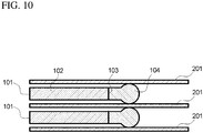
- gaskets 101 are arranged between the stack members 201 at the peripheries of the stack members 201.
- Each gasket 101 includes, for example, a frame 102 and a sealant 104 bonded to a sealing edge (inner periphery) 103 of the frame 102 (refer to, for example, Japanese Patent Application Publication No. 2011-238364 ).
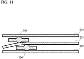
- the sealants 104 between the stack members 201 that are stacked on one another can be misaligned, and the stack members 201 can have misaligned sealing surfaces.
- Such stack members (thin metal films) 201 can bend and have inappropriate tightening margins.
- the gaskets 101 with frames allow sealants 104 to be initially positioned with high accuracy. These gaskets 101 can have sealing surfaces without misalignment when the stack members 201 are stacked on one another and the sealants 104 are compressed, and thus provide appropriate tightening margins without causing the stack members 201 to bend.
- Known framed gaskets 101 used with the stack members 201 stacked on one another at varying intervals (tightening margins) cannot have appropriate sealing surfaces, and thus cannot achieve stable sealing performance.
- Increasing the thickness of the sealants 104 to form sealing surfaces may increase the sealing width when the sealants 104 are compressed, and cause the sealants 104 to enter the area for the active material and decrease the effective areas of the electrode plates.
- One or more aspects of the present invention are directed to a secondary battery gasket for use between stack members stacked on one another at varying intervals (tightening margins) to allow the stack members to have appropriate sealing surfaces and achieve stable sealing performance, and to minimize the increase in the sealing width when a sealant is compressed.
- One or more aspects of the embodiment provides a gasket for a secondary battery placeable between stack members of a secondary battery, the gasket including:
- the gasket for a secondary battery allows stack members stacked on one another at varying intervals (tightening margins) to have appropriate sealing surfaces and to achieve stable sealing performance, and to minimize the increase in the sealing width when a sealant is compressed.
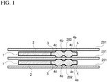
- FIG. 1 is a cross-sectional view of gaskets for a secondary battery according to a first embodiment.
- the figures herein show one to five gaskets 1 for a secondary battery, more gaskets 1 for a secondary battery are actually stacked on one another.
- the middle portions of the stack members 201 and frames 2 are on the right, and the peripheries of the stack members 201 and the frames 2 are on the left.
- a stacked secondary battery including many cell stacks on one another includes gaskets 1 for a secondary battery to seal between the flat stack members 201 in each cell stack at the peripheries of the stack members 201.
- the stack members 201 include a positive electrode plate, a negative electrode plate, and a separator placed between the electrode plates.
- the separator is, for example, a microporous film.
- the spaces between the electrode plates and the separator are filled with an active material.
- Each gasket 1 for a secondary battery includes a flat frame 2 and an annular sealant 4.
- the frame 2 is shaped to extend along a sealing target portion 202 of the stack member 201 at the periphery.
- the sealant 4 is bonded to a sealing edge (inner periphery) 3 of the frame 2.
- the frame 2 is formed from a hard material.
- the frame 2 is preferably formed from a metal, a synthetic resin, a fiber reinforced synthetic resin, or fiber reinforced rubber.
- the sealant 4 is formed from an elastic material, such as rubber, or a synthetic rubber material (a low-hardness material).
- the sealant 4 is bonded to the frame 2 by, for example, integral vulcanization molding.
- the gasket 1 for a secondary battery includes the frame 2, and is easily attachable.
- the frame 2 can hold the sealant 4 at the initial accurate positions, and reduce misalignment of the sealing surfaces of the stack members 201 stacked on one another when the sealant 4 is compressed. This structure allows the stack members 201 to be less likely to bend, and thus can provide appropriate tightening margins.
- the sealant 4 includes an annular sealing bead 4a.
- the sealing bead 4a extends along the entire length of the sealing edge 3, and has a thickness greater than the interval between two adjacent stack members 201.
- the sealing bead 4a is an annular ridge on each of the front and back surfaces of the sealant 4.
- the sealing bead 4a includes at least one annular recess 4b extending along the entire length of the sealing edge 3.
- a single annular recess 4b is formed on each of the front and back surfaces of the sealant 4.
- the annular recesses 4b on the front and back surfaces of the sealant 4 have the same shape and are located opposite to each other across the sealant 4.
- Each annular recess 4b in the sealing bead 4a defines two seal parts 4c with the annular recess 4b between them.
- the sealing bead 4a and the annular recesses 4b are formed integrally with the sealant 4 in a rubber mold when the frame 2 and the sealant 4 are formed by integral vulcanization molding.
- FIGs. 2A and 2B are cross-sectional views showing a comparison between the gasket for a secondary battery according to the first embodiment and a known gasket for a secondary battery.
- the sealing bead 4a is compressed when the frame 2 of the first embodiment is placed between two adjacent stack members 201, thus sealing between the stack members 201 at the sealing target portions 202.
- the compressed sealing bead 4a increases the sealing width as indicated by an arrow E.
- FIG. 3 is a cross-sectional view of the gaskets for a secondary battery according to the first embodiment in use.
- the sealing bead 4a includes the annular recesses 4b. This structure increases the contact area of the seal, allowing the stack members 201 at varying intervals and thus with unstable tightening margins to have appropriate sealing surfaces and to achieve stable sealing performance.
- the structure according to the present embodiment in FIG. 2A including the sealing bead 4a with the annular recesses 4b is filled with less rubber material than the known gasket 101 for a secondary battery shown in FIG. 2B that simply includes a single bead 4a elongated horizontally and having no annular recess 4b.
- the gasket 1 according to the present embodiment minimizes the decrease in the effective areas of the stack members 201 resulting from the increase in the sealing width when the sealing beads 4a are compressed.
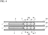
- FIG. 4 is a cross-sectional view of gaskets for a secondary battery with two annular recesses.
- three seal parts 4c may be defined to have each of the two annular recesses 4b between them.
- This structure is filled with less rubber material than the structure including a single annular recess 4b, and thus further reduces the increase in the sealing width when the sealing beads 4a are compressed.
- FIG. 5 is a cross-sectional view of gaskets for a secondary battery with three annular recesses.
- seal parts 4c may be defined to have each of three or more annular recesses 4b between them.
- This structure is filled with less rubber material than the structure including two annular recesses 4b, and thus further reduces the increase in the sealing width when the sealing beads 4a are compressed.
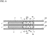
- FIG. 6 is a cross-sectional view of gaskets for a secondary battery with different numbers of annular recesses on the front and back surfaces of the sealants.
- annular recesses 4b When two or more annular recesses 4b are formed, different numbers of annular recesses 4b may be formed on the front and back surfaces of the sealant 4. As shown in FIG. 6 , for example, the front surface of the sealant 4 may have two annular recesses 4b, and the back surface of the sealant 4 may have three annular recesses 4b. When the same number of annular recesses 4b are formed on each of the front and back surfaces of the sealant 4, the annular recesses 4b on the respective surfaces may be at different positions or in different shapes.
- the annular recesses 4b varying in their number, positions, or shapes between the front and back surfaces of the sealant 4 provide the front and back surfaces of the sealant 4 with different appropriate seal pressures.
- This structure accommodates asymmetry (such as curvature) between the front and back surfaces of the stack members 201.
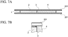
- FIG. 7A is a cross-sectional view of an example compressed gasket for a secondary battery
- FIG. 7B is an enlarged partial cross-sectional view of FIG. 7A .
- a portion of the sealant 4 may deform and be placed between the frame 2 and the stack member 201, as shown in FIG. 7B . In this case, the sealant 4 cannot be compressed to a predetermined thickness.
- FIG. 8 is a cross-sectional view of a gasket for a secondary battery according to a second embodiment. The same components as those described in the first embodiment will not be described.
- a frame 2 in the present embodiment includes a recess 2a on its surface near the sealing edge 3.
- the recess 2a extends along the entire length of the sealing edge 3.
- the frame 2 including the recess 2a has a thickness near the sealing edge 3 smaller than the interval between the adjacent stack members 201 when the sealing beads 4a are compressed.
- the thinner portion near the sealing edge 3 forms a space between the portion near the sealing edge 3 and the stack member 201. This prevents a portion of the sealant 4 from being placed between the frame 2 and the stack member 201. This allows the sealant 4 to be compressed to a predetermined thickness.
- the stack members 201 can thus have appropriate sealing surfaces and achieve stable sealing performance.
- the recess 2a is formed by, for example, squeezing the frame 2 in a rubber mold when the frame 2 and the sealant 4 are formed by integral vulcanization molding. In this manner, the recess 2a can be easily formed on the frame 2.
- FIG. 9 is a cross-sectional view of a gasket for a secondary battery according to a third embodiment. The same components as those described in the first or second embodiment will not be described.
- a frame 2 in the present embodiment includes recesses 2a and 2b formed on each of the front and back surfaces of the frame 2 near the sealing edge 3.
- the frame 2 including the recesses 2a and 2b has a thickness near the sealing edge 3 smaller than the interval between the adjacent stack members 201 when the sealing beads 4a are compressed.
- the thinner portion near the sealing edge 3 forms spaces between the portions near the sealing edge 3 and the stack members 201 on both the front and back surfaces of the frame 2. This prevents a portion of the sealant 4 from being placed between the frame 2 and the stack members 201. This allows the sealant 4 to be compressed to a predetermined thickness.
- the stack members 201 can thus have appropriate sealing surfaces and achieve stable sealing performance.
- the recesses 2a and 2b are formed by, for example, squeezing the frame 2 in a rubber mold when the frame 2 and the sealant 4 are formed by integral vulcanization molding. In this manner, the recesses 2a and 2b can be easily formed on the frame 2.
Landscapes
- Chemical & Material Sciences (AREA)
- Chemical Kinetics & Catalysis (AREA)
- Electrochemistry (AREA)
- General Chemical & Material Sciences (AREA)
- Engineering & Computer Science (AREA)
- General Engineering & Computer Science (AREA)
- Manufacturing & Machinery (AREA)
- Mechanical Engineering (AREA)
- Sealing Battery Cases Or Jackets (AREA)
- Gasket Seals (AREA)
- Secondary Cells (AREA)
Abstract
A secondary battery gasket for use between stack members stacked on one another at varying intervals (tightening margins) allows the stack members to have appropriate sealing surfaces and achieve stable sealing performance, and minimizes the increase in the sealing width when a sealant is compressed. A gasket (1) for a secondary battery placeable between stack members (201) of a secondary battery includes a flat frame (2) shaped to extend along sealing target portions on peripheries of the stack members, and an annular sealant (4) bonded to a sealing edge of the frame and made of elastic material. The annular sealant (4) includes an annular sealing bead (4a) extending along an entire length of the sealing edge (3) and having a thickness greater than an interval between adjacent stack members (201). The sealing bead (4a) has at least one annular recess (4b) along the entire length of the sealing edge (3).
Description
- The present invention relates to a gasket for a secondary battery.
- In a stacked secondary battery including many cell stacks on one another, each cell stack includes a positive electrode plate and a negative electrode plate as flat stack members, and a separator placed between the electrode plates. The spaces between the electrode plates and the separator are filled with an active material. The stack members are clamped together in the stacking direction with bolts and nuts, for example.
- As shown in
FIG. 10 ,gaskets 101 are arranged between thestack members 201 at the peripheries of thestack members 201. Eachgasket 101 includes, for example, aframe 102 and asealant 104 bonded to a sealing edge (inner periphery) 103 of the frame 102 (refer to, for example, Japanese Patent Application Publication No.2011-238364 - As shown in
FIG. 11 , thesealants 104 between thestack members 201 that are stacked on one another can be misaligned, and thestack members 201 can have misaligned sealing surfaces. Such stack members (thin metal films) 201 can bend and have inappropriate tightening margins. Thegaskets 101 with frames allowsealants 104 to be initially positioned with high accuracy. Thesegaskets 101 can have sealing surfaces without misalignment when thestack members 201 are stacked on one another and thesealants 104 are compressed, and thus provide appropriate tightening margins without causing thestack members 201 to bend. - Known framed
gaskets 101 used with thestack members 201 stacked on one another at varying intervals (tightening margins) cannot have appropriate sealing surfaces, and thus cannot achieve stable sealing performance. - Increasing the thickness of the
sealants 104 to form sealing surfaces may increase the sealing width when thesealants 104 are compressed, and cause thesealants 104 to enter the area for the active material and decrease the effective areas of the electrode plates. - One or more aspects of the present invention are directed to a secondary battery gasket for use between stack members stacked on one another at varying intervals (tightening margins) to allow the stack members to have appropriate sealing surfaces and achieve stable sealing performance, and to minimize the increase in the sealing width when a sealant is compressed.
- One or more aspects of the embodiment provides a gasket for a secondary battery placeable between stack members of a secondary battery, the gasket including:
- a flat frame shaped to extend along sealing target portions on peripheries of the stack members; and
- an annular sealant bonded to a sealing edge of the frame, the annular sealant being made of elastic material, the annular sealant including an annular sealing bead extending along an entire length of the sealing edge and having a thickness greater than an interval between adjacent ones of the stack members, the sealing bead having at least one annular recess along the entire length of the sealing edge.
- The gasket for a secondary battery according to the above embodiments of the present invention allows stack members stacked on one another at varying intervals (tightening margins) to have appropriate sealing surfaces and to achieve stable sealing performance, and to minimize the increase in the sealing width when a sealant is compressed.
-
-
FIG. 1 is a cross-sectional view of gaskets for a secondary battery according to a first embodiment. -
FIG. 2A is a cross-sectional view of a gasket for a secondary battery according to the first embodiment, andFIG. 2B is a cross-sectional view of a known gasket for a secondary battery. -
FIG. 3 is a cross-sectional view of the gaskets for a secondary battery according to the first embodiment in use. -
FIG. 4 is a cross-sectional view of gaskets for a secondary battery with two annular recesses. -
FIG. 5 is a cross-sectional view of gaskets for a secondary battery with three annular recesses. -
FIG. 6 is a cross-sectional view of gaskets for a secondary battery with different numbers of annular recesses at the front and back surfaces of the sealants. -
FIG. 7A is a cross-sectional view of an example gasket for a secondary battery when compressed, andFIG. 7B is an enlarged partial cross-sectional view ofFIG. 7A . -
FIG. 8 is a cross-sectional view of a gasket for a secondary battery according to a second embodiment. -
FIG. 9 is a cross-sectional view of a gasket for a secondary battery according to a third embodiment. -
FIG. 10 is a cross-sectional view of known gaskets for a secondary battery. -
FIG. 11 is a cross-sectional view describing an issue with known gaskets for a secondary battery. - Embodiments of the present invention will now be described below with reference to the drawings.
-
FIG. 1 is a cross-sectional view of gaskets for a secondary battery according to a first embodiment. Although the figures herein show one to fivegaskets 1 for a secondary battery,more gaskets 1 for a secondary battery are actually stacked on one another. In the figures, the middle portions of thestack members 201 andframes 2 are on the right, and the peripheries of thestack members 201 and theframes 2 are on the left. - As shown in
FIG. 1 , a stacked secondary battery including many cell stacks on one another includesgaskets 1 for a secondary battery to seal between theflat stack members 201 in each cell stack at the peripheries of thestack members 201. Thestack members 201 include a positive electrode plate, a negative electrode plate, and a separator placed between the electrode plates. The separator is, for example, a microporous film. - The spaces between the electrode plates and the separator are filled with an active material.
- Each
gasket 1 for a secondary battery includes aflat frame 2 and anannular sealant 4. Theframe 2 is shaped to extend along a sealingtarget portion 202 of thestack member 201 at the periphery. Thesealant 4 is bonded to a sealing edge (inner periphery) 3 of theframe 2. Theframe 2 is formed from a hard material. Theframe 2 is preferably formed from a metal, a synthetic resin, a fiber reinforced synthetic resin, or fiber reinforced rubber. Thesealant 4 is formed from an elastic material, such as rubber, or a synthetic rubber material (a low-hardness material). Thesealant 4 is bonded to theframe 2 by, for example, integral vulcanization molding. - The
gasket 1 for a secondary battery includes theframe 2, and is easily attachable. Theframe 2 can hold thesealant 4 at the initial accurate positions, and reduce misalignment of the sealing surfaces of thestack members 201 stacked on one another when thesealant 4 is compressed. This structure allows thestack members 201 to be less likely to bend, and thus can provide appropriate tightening margins. - The
sealant 4 includes anannular sealing bead 4a. Thesealing bead 4a extends along the entire length of the sealingedge 3, and has a thickness greater than the interval between twoadjacent stack members 201. The sealingbead 4a is an annular ridge on each of the front and back surfaces of thesealant 4. - The
sealing bead 4a includes at least oneannular recess 4b extending along the entire length of the sealingedge 3. In the present embodiment, a singleannular recess 4b is formed on each of the front and back surfaces of thesealant 4. Theannular recesses 4b on the front and back surfaces of thesealant 4 have the same shape and are located opposite to each other across thesealant 4. - Each
annular recess 4b in the sealingbead 4a defines twoseal parts 4c with theannular recess 4b between them. - The sealing
bead 4a and theannular recesses 4b are formed integrally with thesealant 4 in a rubber mold when theframe 2 and thesealant 4 are formed by integral vulcanization molding. -
FIGs. 2A and 2B are cross-sectional views showing a comparison between the gasket for a secondary battery according to the first embodiment and a known gasket for a secondary battery. - As shown in
FIG. 2A , the sealingbead 4a is compressed when theframe 2 of the first embodiment is placed between twoadjacent stack members 201, thus sealing between thestack members 201 at the sealingtarget portions 202. Thecompressed sealing bead 4a increases the sealing width as indicated by an arrow E. -
FIG. 3 is a cross-sectional view of the gaskets for a secondary battery according to the first embodiment in use. - As shown in
FIG. 3 , in the present embodiment, the sealingbead 4a includes theannular recesses 4b. This structure increases the contact area of the seal, allowing thestack members 201 at varying intervals and thus with unstable tightening margins to have appropriate sealing surfaces and to achieve stable sealing performance. - The structure according to the present embodiment in
FIG. 2A including the sealingbead 4a with theannular recesses 4b is filled with less rubber material than the knowngasket 101 for a secondary battery shown inFIG. 2B that simply includes asingle bead 4a elongated horizontally and having noannular recess 4b. As indicated by the arrow E, thegasket 1 according to the present embodiment minimizes the decrease in the effective areas of thestack members 201 resulting from the increase in the sealing width when the sealingbeads 4a are compressed. -
FIG. 4 is a cross-sectional view of gaskets for a secondary battery with two annular recesses. - As shown in
FIG. 4 , threeseal parts 4c may be defined to have each of the twoannular recesses 4b between them. This structure is filled with less rubber material than the structure including a singleannular recess 4b, and thus further reduces the increase in the sealing width when the sealingbeads 4a are compressed. -
FIG. 5 is a cross-sectional view of gaskets for a secondary battery with three annular recesses. - As shown in
FIG. 5 , four ormore seal parts 4c may be defined to have each of three or moreannular recesses 4b between them. This structure is filled with less rubber material than the structure including twoannular recesses 4b, and thus further reduces the increase in the sealing width when the sealingbeads 4a are compressed. -
FIG. 6 is a cross-sectional view of gaskets for a secondary battery with different numbers of annular recesses on the front and back surfaces of the sealants. - When two or more
annular recesses 4b are formed, different numbers ofannular recesses 4b may be formed on the front and back surfaces of thesealant 4. As shown inFIG. 6 , for example, the front surface of thesealant 4 may have twoannular recesses 4b, and the back surface of thesealant 4 may have threeannular recesses 4b. When the same number ofannular recesses 4b are formed on each of the front and back surfaces of thesealant 4, theannular recesses 4b on the respective surfaces may be at different positions or in different shapes. - The
annular recesses 4b varying in their number, positions, or shapes between the front and back surfaces of thesealant 4 provide the front and back surfaces of thesealant 4 with different appropriate seal pressures. This structure accommodates asymmetry (such as curvature) between the front and back surfaces of thestack members 201. -
FIG. 7A is a cross-sectional view of an example compressed gasket for a secondary battery, andFIG. 7B is an enlarged partial cross-sectional view ofFIG. 7A . - When a
sealant 4 of agasket 1 for a secondary battery is compressed, a portion of the sealant 4 (near a sealing edge 3) may deform and be placed between theframe 2 and thestack member 201, as shown inFIG. 7B . In this case, thesealant 4 cannot be compressed to a predetermined thickness. -
FIG. 8 is a cross-sectional view of a gasket for a secondary battery according to a second embodiment. The same components as those described in the first embodiment will not be described. - A
frame 2 in the present embodiment includes arecess 2a on its surface near the sealingedge 3. Therecess 2a extends along the entire length of the sealingedge 3. Theframe 2 including therecess 2a has a thickness near the sealingedge 3 smaller than the interval between theadjacent stack members 201 when the sealingbeads 4a are compressed. - The thinner portion near the sealing
edge 3 forms a space between the portion near the sealingedge 3 and thestack member 201. This prevents a portion of thesealant 4 from being placed between theframe 2 and thestack member 201. This allows thesealant 4 to be compressed to a predetermined thickness. Thestack members 201 can thus have appropriate sealing surfaces and achieve stable sealing performance. - The
recess 2a is formed by, for example, squeezing theframe 2 in a rubber mold when theframe 2 and thesealant 4 are formed by integral vulcanization molding. In this manner, therecess 2a can be easily formed on theframe 2. -
FIG. 9 is a cross-sectional view of a gasket for a secondary battery according to a third embodiment. The same components as those described in the first or second embodiment will not be described. - A
frame 2 in the present embodiment includesrecesses frame 2 near the sealingedge 3. Theframe 2 including therecesses edge 3 smaller than the interval between theadjacent stack members 201 when the sealingbeads 4a are compressed. - The thinner portion near the sealing
edge 3 forms spaces between the portions near the sealingedge 3 and thestack members 201 on both the front and back surfaces of theframe 2. This prevents a portion of thesealant 4 from being placed between theframe 2 and thestack members 201. This allows thesealant 4 to be compressed to a predetermined thickness. Thestack members 201 can thus have appropriate sealing surfaces and achieve stable sealing performance. - The
recesses frame 2 in a rubber mold when theframe 2 and thesealant 4 are formed by integral vulcanization molding. In this manner, therecesses frame 2. -
- 1
- gasket for secondary battery
- 2
- frame
- 2a, 2b
- recess
- 3
- sealing edge
- 4
- sealant
- 4a
- sealing bead
- 4b
- annular recess
- 4c
- seal part
- 201
- stack member
- 202
- sealing target portion
Claims (5)
- A gasket for a secondary battery placeable between stack members of a secondary battery, the gasket comprising:a flat frame shaped to extend along sealing target portions on peripheries of the stack members; andan annular sealant bonded to a sealing edge of the frame, the annular sealant being made of elastic material, the annular sealant including an annular sealing bead extending along an entire length of the sealing edge and having a thickness greater than an interval between adjacent ones of the stack members, the sealing bead having at least one annular recess along the entire length of the sealing edge.
- The gasket for a secondary battery according to claim 1, wherein
the sealing bead includes at least two annular recesses. - The gasket for a secondary battery according to claim 1 or claim 2, wherein
the frame includes a recess on one surface of the sealing edge. - The gasket for a secondary battery according to claim 1 or claim 2, wherein
the frame includes a recess on each of two surfaces of the sealing edge. - The gasket for a secondary battery according to any one of claims 1 to 4, w
herein
the frame has a thickness at the sealing edge smaller than the interval between adjacent ones of the stack members.
Applications Claiming Priority (2)
| Application Number | Priority Date | Filing Date | Title |
|---|---|---|---|
| JP2017136589 | 2017-07-12 | ||
| PCT/JP2018/023867 WO2019012961A1 (en) | 2017-07-12 | 2018-06-22 | Gasket for secondary battery |
Publications (1)
| Publication Number | Publication Date |
|---|---|
| EP3654403A1 true EP3654403A1 (en) | 2020-05-20 |
Family
ID=65001590
Family Applications (1)
| Application Number | Title | Priority Date | Filing Date |
|---|---|---|---|
| EP18832709.2A Withdrawn EP3654403A1 (en) | 2017-07-12 | 2018-06-22 | Gasket for secondary battery |
Country Status (5)
| Country | Link |
|---|---|
| US (1) | US20210143502A1 (en) |
| EP (1) | EP3654403A1 (en) |
| JP (1) | JPWO2019012961A1 (en) |
| CN (1) | CN110679000A (en) |
| WO (1) | WO2019012961A1 (en) |
Families Citing this family (5)
| Publication number | Priority date | Publication date | Assignee | Title |
|---|---|---|---|---|
| DE202019102113U1 (en) * | 2019-04-12 | 2020-07-16 | Reinz-Dichtungs-Gmbh | Hinged seal with continuous sealing contour |
| DE202020104066U1 (en) * | 2020-07-14 | 2021-10-18 | Reinz-Dichtungs-Gmbh | Seal and housing with a seal |
| JP2025139389A (en) * | 2024-03-12 | 2025-09-26 | Nok株式会社 | gasket |
| KR20250138589A (en) * | 2024-03-13 | 2025-09-22 | 주식회사 엘지에너지솔루션 | Battery case, battery pack and vehicle comprising the same |
| WO2026088340A1 (en) * | 2024-10-23 | 2026-04-30 | 日産自動車株式会社 | Secondary battery and method for manufacturing same |
Family Cites Families (12)
| Publication number | Priority date | Publication date | Assignee | Title |
|---|---|---|---|---|
| US6596427B1 (en) * | 2000-11-06 | 2003-07-22 | Ballard Power Systems Inc. | Encapsulating seals for electrochemical cell stacks and methods of sealing electrochemical cell stacks |
| JP2002358949A (en) * | 2001-05-30 | 2002-12-13 | Nec Tokin Corp | Battery manufacturing method |
| JP3975940B2 (en) * | 2003-02-21 | 2007-09-12 | トヨタ自動車株式会社 | Electricity storage element |
| JP5142530B2 (en) * | 2004-10-08 | 2013-02-13 | パナソニック株式会社 | Polymer electrolyte fuel cell |
| KR100686827B1 (en) * | 2005-07-11 | 2007-02-26 | 삼성에스디아이 주식회사 | Lithium secondary battery |
| JP4842023B2 (en) * | 2006-06-14 | 2011-12-21 | 日本バルカー工業株式会社 | Serrated gasket |
| WO2010100906A1 (en) * | 2009-03-04 | 2010-09-10 | パナソニック株式会社 | Polymer electrolyte type fuel cell gasket |
| JP5617268B2 (en) * | 2009-05-19 | 2014-11-05 | Nok株式会社 | Fuel cell sealing structure |
| JP5468457B2 (en) | 2010-05-06 | 2014-04-09 | 内山工業株式会社 | Gasket for fuel cell and fuel cell seal structure |
| JP5725277B2 (en) * | 2010-06-14 | 2015-05-27 | Nok株式会社 | gasket |
| KR20130099975A (en) * | 2010-09-21 | 2013-09-06 | 신코베덴키 가부시키가이샤 | Nonaqueous Electrolyte Secondary Battery |
| CN105247263B (en) * | 2013-05-31 | 2017-09-19 | 协和工业株式会社 | Flange connection and the seal for the structure |
-
2018
- 2018-06-22 WO PCT/JP2018/023867 patent/WO2019012961A1/en not_active Ceased
- 2018-06-22 JP JP2019529029A patent/JPWO2019012961A1/en active Pending
- 2018-06-22 CN CN201880034797.3A patent/CN110679000A/en active Pending
- 2018-06-22 US US16/621,719 patent/US20210143502A1/en not_active Abandoned
- 2018-06-22 EP EP18832709.2A patent/EP3654403A1/en not_active Withdrawn
Also Published As
| Publication number | Publication date |
|---|---|
| CN110679000A (en) | 2020-01-10 |
| JPWO2019012961A1 (en) | 2020-02-27 |
| US20210143502A1 (en) | 2021-05-13 |
| WO2019012961A1 (en) | 2019-01-17 |
Similar Documents
| Publication | Publication Date | Title |
|---|---|---|
| US20210143502A1 (en) | Gasket for secondary battery | |
| US10199663B2 (en) | Cell structure for fuel cell stack | |
| CA2369182A1 (en) | Resilient seals between separator plates in a fuel cell stack | |
| US11005121B2 (en) | Gasket and fuel cell stack | |
| US9947910B2 (en) | Energy storage apparatus and spacer | |
| US20170279133A1 (en) | Bipolar plate assembly with integrated seal for fuel cell | |
| KR102532102B1 (en) | Gasket and its manufacturing method | |
| US10340482B2 (en) | Energy storage apparatus | |
| US20230048295A1 (en) | Apparatus and Method for Pressing Secondary Battery | |
| KR20180056219A (en) | Spacer and battery assembly comprising thereof | |
| WO2014080760A1 (en) | Fuel cell stack | |
| US10865881B2 (en) | Gasket and method for mounting same | |
| US10608260B2 (en) | Gasket and method of manufacturing the same | |
| CN111640958A (en) | A fuel cell single cell and fuel cell | |
| JP4337394B2 (en) | Fuel cell | |
| JP2015191802A (en) | fuel cell stack | |
| US12136749B2 (en) | Seal structure for fuel cell separator | |
| JP5293949B2 (en) | gasket | |
| CN221596489U (en) | Electrode frame of flow battery | |
| JP7130610B2 (en) | Metal separators for fuel cells, junction separators and power generation cells | |
| JP6611226B2 (en) | Storage device seal structure | |
| JP2022121879A (en) | Manufacturing method of bead seal structure and bead seal structure | |
| MX2022009322A (en) | ONE FILTER DIAPHRAGM FOR A RECESSED PLATE TYPE FILTER, ONE DIAPHRAGM FILTER PLATE, ONE DIAPHRAGM FILTER PLATE ASSEMBLY, AND ONE RECESSED PLATE TYPE FILTER. | |
| KR20180050416A (en) | Fuel cell stack | |
| JP7111661B2 (en) | Metal separators for fuel cells, junction separators and power generation cells |
Legal Events
| Date | Code | Title | Description |
|---|---|---|---|
| PUAI | Public reference made under article 153(3) epc to a published international application that has entered the european phase |
Free format text: ORIGINAL CODE: 0009012 |
|
| STAA | Information on the status of an ep patent application or granted ep patent |
Free format text: STATUS: REQUEST FOR EXAMINATION WAS MADE |
|
| 17P | Request for examination filed |
Effective date: 20191126 |
|
| AK | Designated contracting states |
Kind code of ref document: A1 Designated state(s): AL AT BE BG CH CY CZ DE DK EE ES FI FR GB GR HR HU IE IS IT LI LT LU LV MC MK MT NL NO PL PT RO RS SE SI SK SM TR |
|
| AX | Request for extension of the european patent |
Extension state: BA ME |
|
| DAV | Request for validation of the european patent (deleted) | ||
| DAX | Request for extension of the european patent (deleted) | ||
| 18W | Application withdrawn |
Effective date: 20210216 |