EP3654119A1 - Force control device, force control method, and force control program - Google Patents
Force control device, force control method, and force control program Download PDFInfo
- Publication number
- EP3654119A1 EP3654119A1 EP18832753.0A EP18832753A EP3654119A1 EP 3654119 A1 EP3654119 A1 EP 3654119A1 EP 18832753 A EP18832753 A EP 18832753A EP 3654119 A1 EP3654119 A1 EP 3654119A1
- Authority
- EP
- European Patent Office
- Prior art keywords
- force
- virtual object
- torque
- target
- control
- Prior art date
- Legal status (The legal status is an assumption and is not a legal conclusion. Google has not performed a legal analysis and makes no representation as to the accuracy of the status listed.)
- Withdrawn
Links
Images




Classifications
-
- B—PERFORMING OPERATIONS; TRANSPORTING
- B25—HAND TOOLS; PORTABLE POWER-DRIVEN TOOLS; MANIPULATORS
- B25J—MANIPULATORS; CHAMBERS PROVIDED WITH MANIPULATION DEVICES
- B25J9/00—Program-controlled manipulators
- B25J9/16—Program controls
- B25J9/1628—Program controls characterised by the control loop
- B25J9/1633—Program controls characterised by the control loop compliant, force, torque control, e.g. combined with position control
-
- B—PERFORMING OPERATIONS; TRANSPORTING
- B25—HAND TOOLS; PORTABLE POWER-DRIVEN TOOLS; MANIPULATORS
- B25J—MANIPULATORS; CHAMBERS PROVIDED WITH MANIPULATION DEVICES
- B25J13/00—Controls for manipulators
- B25J13/08—Controls for manipulators by means of sensing devices, e.g. viewing or touching devices
- B25J13/085—Force or torque sensors
-
- G—PHYSICS
- G05—CONTROLLING; REGULATING
- G05B—CONTROL OR REGULATING SYSTEMS IN GENERAL; FUNCTIONAL ELEMENTS OF SUCH SYSTEMS; MONITORING OR TESTING ARRANGEMENTS FOR SUCH SYSTEMS OR ELEMENTS
- G05B13/00—Adaptive control systems, i.e. systems automatically adjusting themselves to have a performance which is optimum according to some preassigned criterion
- G05B13/02—Adaptive control systems, i.e. systems automatically adjusting themselves to have a performance which is optimum according to some preassigned criterion electric
- G05B13/04—Adaptive control systems, i.e. systems automatically adjusting themselves to have a performance which is optimum according to some preassigned criterion electric involving the use of models or simulators
- G05B13/041—Adaptive control systems, i.e. systems automatically adjusting themselves to have a performance which is optimum according to some preassigned criterion electric involving the use of models or simulators in which a variable is automatically adjusted to optimise the performance
-
- G—PHYSICS
- G06—COMPUTING OR CALCULATING; COUNTING
- G06F—ELECTRIC DIGITAL DATA PROCESSING
- G06F30/00—Computer-aided design [CAD]
- G06F30/20—Design optimisation, verification or simulation
-
- G—PHYSICS
- G05—CONTROLLING; REGULATING
- G05B—CONTROL OR REGULATING SYSTEMS IN GENERAL; FUNCTIONAL ELEMENTS OF SUCH SYSTEMS; MONITORING OR TESTING ARRANGEMENTS FOR SUCH SYSTEMS OR ELEMENTS
- G05B2219/00—Program-control systems
- G05B2219/30—Nc systems
- G05B2219/39—Robotics, robotics to robotics hand
- G05B2219/39323—Force and motion control
-
- G—PHYSICS
- G05—CONTROLLING; REGULATING
- G05B—CONTROL OR REGULATING SYSTEMS IN GENERAL; FUNCTIONAL ELEMENTS OF SUCH SYSTEMS; MONITORING OR TESTING ARRANGEMENTS FOR SUCH SYSTEMS OR ELEMENTS
- G05B2219/00—Program-control systems
- G05B2219/30—Nc systems
- G05B2219/39—Robotics, robotics to robotics hand
- G05B2219/39332—Adaptive force control
-
- G—PHYSICS
- G05—CONTROLLING; REGULATING
- G05B—CONTROL OR REGULATING SYSTEMS IN GENERAL; FUNCTIONAL ELEMENTS OF SUCH SYSTEMS; MONITORING OR TESTING ARRANGEMENTS FOR SUCH SYSTEMS OR ELEMENTS
- G05B2219/00—Program-control systems
- G05B2219/30—Nc systems
- G05B2219/42—Servomotor, servo controller kind till VSS
- G05B2219/42326—Protection servo for saturation of amplifier
-
- G—PHYSICS
- G06—COMPUTING OR CALCULATING; COUNTING
- G06F—ELECTRIC DIGITAL DATA PROCESSING
- G06F17/00—Digital computing or data processing equipment or methods, specially adapted for specific functions
- G06F17/10—Complex mathematical operations
- G06F17/11—Complex mathematical operations for solving equations, e.g. nonlinear equations, general mathematical optimization problems
Definitions
- the present invention relates to a force control device that performs admittance control using a force sensor, and the like.
- Non-Patent Literatures 1 and 2 When a robot manipulator is operating in contact with an external environment, an appropriate controller is needed to control a contact force between an end effector of the robot and the environment.
- This type of controller has been proposed in Non-Patent Literatures 1 and 2.
- a control method called admittance control (Non-Patent Literature 3) is often used (Non-Patent Literatures 3 to 5).
- This type of controller assumes a virtual object having simple dynamic characteristics in a controller, and simulates a motion of the virtual object using information on a force measured by the force sensor. The position of a robot is controlled so as to track the motion of the virtual object.
- Non-Patent Literatures 4 and 5 force sense presentation
- Non-Patent Literature 6 remote control
- rehabilitation Non-Patent Literature 7
- human-machine collaborative work Non-Patent Literature 8
- some kind of manufacturing processes Non-Patent Literature 9
- One of the problems of an actuator force saturation in the admittance control is that the position of a robot tends to move away from that of a virtual object when an actuator force is saturated.
- the actuator force may be saturated and an abrupt change in the speed of the virtual object may occur.
- it will result in sluggish responsiveness to a contact force, which is often inappropriate.
- Non-Patent Literatures 11 to 13 an explicit force controller
- Non-Patent Literatures 14 to 17 an impedance controller
- the former controls the force on an end effector
- the latter controls the apparent mechanical impedance of the end effector.
- Non-Patent Literatures 9 and 18 virtual internal model following control
- Non-Patent Literatures 19 and 20 position control based impedance control
- admittance control Ne-Patent Literatures 4, 5, 7, and 8
- Non-Patent Literatures 12 and 23 The main causes of instability are time delay in the controller (Non-Patent Literatures 12 and 23) and band limitation of an internal position control system (Non-Patent Literatures 24 to 26).
- In order to suppress instability it is known that virtual mass and virtual viscosity should be set high. However, it may degrade the reactivity of the controller, so that high virtual mass or virtual viscosity is not always desirable.
- the minimum feasible virtual mass is also one evaluation index for an admittance-controlled device (Non-Patent Literature 5). In order to improve the stability without increasing the virtual mass and the virtual viscosity, the transfer function from a virtual object position to an actual position needs to be close to 1.
- Non-Patent Literatures 22, 27, and 28 use a position controller including a feedforward term (which can be regarded as a phase lead compensator) to compensate for the effect of dynamic characteristics of a robot.
- Non-Patent Literature 29 the only analytical study on the problem of how to avoid it is the work of Gonzalez and Widmann. This study points out that saturation improves stability of a control target because saturation temporarily makes the system equivalent to an open-loop system. However, this technique does not take into account such a situation where positive and negative saturations occur alternately, which is usually undesirable.
- a control technique that can be used to solve such a problem is the proxy-based sliding mode control (PSMC) proposed by Non-Patent Literature 10 and Non-Patent Literature 1.
- PSMC proxy-based sliding mode control
- This technique comprises not only some kind of discrete-time approximation of a simple sliding mode controller but also an extension of a PID controller in which saturation may occur.
- the PSMC is equivalent to the PID when a torque is unsaturated, so that the current position following characteristic with respect to a target position may be insufficient.
- ⁇ becomes discontinuous at the time of transition from the saturated to the unsaturated, which causes an operator who touches a robot to feel uncomfortable.
- Patent Literature 2 can suppress discontinuous movement even at the time of torque saturation while improving position following capability, but may inevitably cause discomfort when the follow-up processing is performed, because the position of a virtual object and the position of a robot will be separated away from each other.
- the present invention provides a force control device and the like that can, even in the case of torque saturation, reduce positional deviation between a virtual object and a control target by feeding back a position of the virtual object, and improve stability while improving followability.
- a force control device is provided with: a position detector that detects a position of a control target; a force sensor that detects a force by which the control target is in contact with an object; a moving mechanism that movably holds the control target; a driving unit that includes a motor that uses a torque command value as an input to operate the moving mechanism; and a computing unit that determines the torque command value, wherein the computing unit stores a virtual object having predetermined dynamic characteristics, and a position control rule, and is configured to: calculate a position at a next time, the position being calculated by simulating a motion of the virtual object when a target force exerted on the control target and a measured value of the force sensor are given to the virtual object; obtain a torque calculated when the calculated position is given to the position control rule as a target position at the next time; when the obtained torque is within a predetermined range set previously, determine the obtained torque as the torque command value to determine the calculated position as a position of the virtual object at the next time; and when the obtained torque
- the force control device is provided with: a position detector that detects a position of a control target; a force sensor that detects a force by which the control target is in contact with an object; a moving mechanism that movably holds the control target; a driving unit that includes a motor that uses a torque command value as an input to operate the moving mechanism; and a computing unit that determines the torque command value, and when the calculated torque is outside the predetermined range set previously, the position of the virtual object at the next time is determined based on a boundary value of the predetermined range and the calculated torque, so that positional deviation between the virtual object and the control target is reduced, resulting in that it is possible to improve stability while improving followability.
- FIG. 1 is a functional block diagram showing an example of a processing concept of a conventional force control device
- FIG. 2 is a functional block diagram showing an example of a processing concept of a force control device according to the present embodiment.
- an admittance control in the prior art determines a position P d of a virtual object 12 having predetermined dynamic characteristics as a target position based on a measured value f of a force sensor 11 and a target force f d (a force applied to a robot 14 to be controlled).
- a position controller 13 calculates a torque command value ⁇ of a motor of the robot 14 so as to satisfy the target position P d .
- the robot 14 moves to a position P based on a force h applied to the robot 14 from the outside, the measured value f of the force sensor 11, and the torque command value ⁇ .
- the target position P d of the virtual object 12 and the position P of the robot 14 will be deviated from each other when the torque command value ⁇ is outside a torque range (for example, an upper limit value and a lower limit value of a torque set previously according to safety, drive characteristics of the robot 14, environment, and the like).
- a torque range for example, an upper limit value and a lower limit value of a torque set previously according to safety, drive characteristics of the robot 14, environment, and the like.
- the torque command value ⁇ calculated by the position controller 13 is fed back in an algebraic loop, thereby making it possible to match the position q x of the virtual object 12 and the position q s of the robot 14, resulting in that it is possible to eliminate the discomfort in the follow-up processing as conventionally felt.
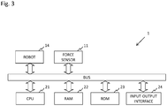
- FIG. 3 is a hardware configuration diagram of the force control device according to the present embodiment.
- a force control device 1 is provided with: the robot 14 to be controlled; the force sensor 11 that is attached to the robot 14 and measures a reaction force from an object in an environment around the robot 14; a ROM 23 that stores a program for performing admittance control, and the like; a CPU 21 that reads the program into a RAM 22 as needed, and executes a processing; and an input-output interface 24 that is an interface for accepting an input from an input device such as a touch panel, a keyboard, or a mouse, and outputting data to a printer, a display, or the like.
- These processing units are connected to each other via a bus and exchange information thereamong.
- the above hardware configuration is merely an example, and may be changed as needed.
- FIG. 4 is a functional block diagram of the force control device according to the present embodiment.
- the force control device 1 is provided with: the robot 14 that applies a predetermined force to an environment; and a computing unit 40 that controls a movement of the robot 14.
- the robot 14 is provided with: the force sensor 11 that measures the reaction force from the object in the surrounding environment; a moving mechanism 41 that moves the robot 14 or a part (such as, for example, an arm) of the robot 14; and a driving unit 42 that includes a motor for driving the moving mechanism 41.
- the computing unit 40 calculates a torque command value of the motor of the driving unit 42 based on a measurement result from the force sensor 11 and position information of the moving mechanism 41 and outputs the torque command value to the driving unit 42. The processing of calculating the torque command value by the computing unit 40 will be described in detail below.
- F be a closed interval on a real number.
- a saturation function and a normal cone therefor are defined as follows. sat F x ⁇ argmin ⁇ ⁇ F ⁇ ⁇ x 2
- the sign function and the normal cone are inversely mapped to each other as described below.
- the position control rule of the robot 14 when the target position is let be q x is given by an appropriate function ⁇ c , as follows.
- ⁇ ⁇ c q x q s q ⁇ x q ⁇ s q ⁇ x ⁇ q x ⁇ q s dt
- ⁇ c q ⁇ x q ⁇ x q x f + f d
- This can be regarded as a simultaneous differential equation in which ⁇ and q x (second order differential) are unknown. Also, this can be represented as a block diagram including an algebraic loop as shown in FIG. 2 .
- N f (.) in the equation (11a) is an argument, ⁇ is not allowed to exist outside F, so that ⁇ must be within F to satisfy the above.
- q x is updated (i.e., q x (second order differential) is determined) such that ⁇ should be within F. If the generated force ⁇ calculated when q x (second order differential) is determined so as to satisfy the expression (10) and is then substituted into the expression (11b) is within F, a value of this ⁇ is adopted as it is. On the other hand, if this ⁇ is outside F, ⁇ saturates at the value closest to ⁇ on the boundary of F, and in this case, q x (second order derivative) is determined so as to satisfy the expression (11b).
- a discrete time expression of the controller (11) will be derived.
- S(k-1) is a set including, for example, an integral term, a measured position q s (k-1) of a preceding step, and a target position p d (k-1) of the preceding step.
- the output value ⁇ (k) of this function is set as a torque command value to a motor.
- S(k) in the next step is determined as follows.
- S k ⁇ S q x k , q s k , S k ⁇ 1
- This S (k) is used as one of input values S(k-1) in the next step.
- the equations (12a) and (12b) can be regarded as simultaneous equations for the unknowns ⁇ (k) and q x (k), which can also be interpreted as the block diagram as shown in FIG. 2 .
- This function ⁇ inv can be called an inverse controller.
- An ordinary controller gives a torque command value to a target position.
- the reverse controller calculates a target position required to output a designated torque command value.
- controller ⁇ (q x , q s , S) is linear with respect to the target value q x , and many typical controllers ⁇ (q x , q s , S) satisfy this assumption.
- the algorithm (22) becomes as follows.
- the controller function ⁇ c in the continuous time domain is given as ⁇ c q x q s q ⁇ x q ⁇ s q ⁇ x ⁇ q x ⁇ q s dt ⁇ M q ⁇ x + K q x ⁇ q s + B q ⁇ x ⁇ q ⁇ s + L ⁇ q x ⁇ q s dt
- Mq x (q x is the second order differential) is the feedforward term of a target acceleration
- K, B, and L are proportional, differential, and integral gains, respectively.
- a k a k ⁇ 1 + T q s k ⁇ q s k
- A K + B/T + LT and the following expression holds.
- q s ⁇ k A ⁇ q s k + B q x k ⁇ 1 ⁇ q s k ⁇ 1 / T ⁇ La k ⁇ 1 A ⁇ + M / T 2 + M 2 q s k ⁇ 1 ⁇ q x k ⁇ 2 A ⁇ T 2 + M
- the function ⁇ becomes as follows. ⁇ q 1 q 2 f ⁇ 2 M v + B v q 1 ⁇ M v q 2 + T 2 f M v + B v T
- FIG. 5 is a flowchart illustrating the operation of the force control device according to the present embodiment.
- the computing unit 40 performs arithmetic processing of the admittance control based on the force applied from the outside to the robot 14 and the measured value of the force sensor 11 (S1). This arithmetic processing is as described above.
- a motor torque command value for driving the robot 14 is outputted and inputted to the robot 14 (S2).
- the robot 14 is driven according to the torque command value (S3).
- the processing is terminated.
- the position of the virtual object at the next time is determined using the algebraic loop based on the boundary value of the predetermined range and the torque command value, so that positional deviation between the virtual object and the control target is reduced, resulting in that it is possible to improve stability while improving followability.
- FIG. 6 is a photograph of the robot 14 used in the experiment.
- the above-mentioned admittance control rule was implemented in the third joint of the robot 14, and the other joints were locked. Then, the behavior when the operation was performed by contacting the force sensor 11 and the behavior when the operation was performed by contacting a link portion (a portion other than the force sensor 11) were observed.
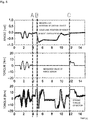
- FIG. 7 is a diagram showing a result of an admittance control when a conventional method was used
- FIG. 8 is a diagram showing a result of an admittance control when the force control device according to the present invention was used.
- measurement results are shown for the respective states as follows:
- the position of the robot 14 follows the position of the virtual object 12 well in any of the methods.
- the state (2) according to the conventional method of FIG. 7 , the position of the robot 14 and the position of the virtual object 12 are deviated from each other. In this case, the position will tend to return to the original position like a spring when the applied force is released, which might be dangerous.
- the position of the virtual object 12 follows the position of the robot 14, so that there would be no such a danger at all even when the applied force is released.
- the state (3) according to the conventional method shown in FIG. 7 , only the position of the virtual object 12 moves.
- the robot 14 will tend to follow the position of the far-away virtual object 12 when the user releases his/her hand, which might be dangerous.
- the position of the virtual object 12 does not move and the position of the robot 14 does not move either, so that there would be no such a danger at all.
- the method of the present invention has significantly improved safety as compared with the conventional method in such a situation where the torque saturation occurs.
Landscapes
- Engineering & Computer Science (AREA)
- Physics & Mathematics (AREA)
- Robotics (AREA)
- Mechanical Engineering (AREA)
- General Physics & Mathematics (AREA)
- Evolutionary Computation (AREA)
- Theoretical Computer Science (AREA)
- Computer Hardware Design (AREA)
- General Engineering & Computer Science (AREA)
- Geometry (AREA)
- Human Computer Interaction (AREA)
- Health & Medical Sciences (AREA)
- Artificial Intelligence (AREA)
- Computer Vision & Pattern Recognition (AREA)
- Medical Informatics (AREA)
- Software Systems (AREA)
- Automation & Control Theory (AREA)
- Feedback Control In General (AREA)
- Manipulator (AREA)
Abstract
Description
- The present invention relates to a force control device that performs admittance control using a force sensor, and the like.
- When a robot manipulator is operating in contact with an external environment, an appropriate controller is needed to control a contact force between an end effector of the robot and the environment. This type of controller has been proposed in
Non-Patent Literatures - One of the problems of an actuator force saturation in the admittance control is that the position of a robot tends to move away from that of a virtual object when an actuator force is saturated. The actuator force may be saturated and an abrupt change in the speed of the virtual object may occur. Setting inertia and viscosity of the virtual object high when there is a possibility that a large external force acts on the robot, contributes to the prevention of the saturation. However, it will result in sluggish responsiveness to a contact force, which is often inappropriate.
- Control methods using an external force feedback loop and an internal position loop can be found in some literatures since the 1970's. Controllers for use in these methods can be classified into an explicit force controller (
Non-Patent Literatures 11 to 13) and an impedance controller (Non-PatentLiteratures 14 to 17). The former controls the force on an end effector, and the latter controls the apparent mechanical impedance of the end effector. These two types can be implemented in a similar framework (the difference is whether a target force command is provided or not). These controllers are referred to as various names such as "virtual internal model following control" (Non-Patent Literatures 9 and 18), "position control based impedance control" (Non-Patent Literatures 19 and 20), and "admittance control" (Non-Patent Literatures 4, 5, 7, and 8). - Stability is a major challenge for an admittance controller. The main causes of instability are time delay in the controller (
Non-Patent Literatures 12 and 23) and band limitation of an internal position control system (Non-PatentLiteratures 24 to 26). In order to suppress instability, it is known that virtual mass and virtual viscosity should be set high. However, it may degrade the reactivity of the controller, so that high virtual mass or virtual viscosity is not always desirable. The minimum feasible virtual mass is also one evaluation index for an admittance-controlled device (Non-Patent Literature 5). In order to improve the stability without increasing the virtual mass and the virtual viscosity, the transfer function from a virtual object position to an actual position needs to be close to 1. In order to achieve this, some of the prior art techniques use a position controller including a feedforward term (which can be regarded as a phase lead compensator) to compensate for the effect of dynamic characteristics of a robot (Non-PatentLiteratures 22, 27, and 28). - With respect to the actuator saturation, the only analytical study on the problem of how to avoid it is the work of Gonzalez and Widmann (Non-Patent Literature 29). This study points out that saturation improves stability of a control target because saturation temporarily makes the system equivalent to an open-loop system. However, this technique does not take into account such a situation where positive and negative saturations occur alternately, which is usually undesirable.
- A control technique that can be used to solve such a problem is the proxy-based sliding mode control (PSMC) proposed by Non-Patent Literature 10 and Non-Patent Literature 1. This technique comprises not only some kind of discrete-time approximation of a simple sliding mode controller but also an extension of a PID controller in which saturation may occur.
- The PSMC is equivalent to the PID when a torque is unsaturated, so that the current position following characteristic with respect to a target position may be insufficient. In the case of PSMC, with respect to the torque saturation, τ becomes discontinuous at the time of transition from the saturated to the unsaturated, which causes an operator who touches a robot to feel uncomfortable. For such a problem, it is disclosed a technique relating to a force control device using the admittance control that is provided with a position controller that can improve position following capability even when a position command changes frequently and suddenly, and can suppress discontinuous movement even when the torque is saturated (Patent Literature 2).
-
- Non-Patent Literature 1 : D. E. Whitney, "Historical perspective and state of the art in robot force control," Int. J. Robotics Research, vol. 6, no. 1, pp. 3-14, 1987.
- Non-Patent Literature 2 : G. Zeng and A. Hemami, "An overview of robot force control," Robotica, vol. 15, pp. 473-482, 1997.
- Non-Patent Literature 3 : C. Ott, R. Mukherjee, and Y. Nakamura, "Unified impedance and admittance control," in Proc. IEEE Int. Conf. Robotics and Automation, 2010, pp. 554-561.
- Non-Patent Literature 4 : M. Ueberle and M. Buss, "Control of kinesthetic haptic interfaces," in Proc. Workshop on Touch and Haptics, IEEE/RSJ Int. Conf. Intelligent Robots and Systems, 2004, pp. 1-14.
- Non-Patent Literature 5 : R. Q. Van Der Linde and P. Lammertse, "HapticMaster - ageneric force controlled robot for human interaction," Industrial Robot, vol. 30, no. 6, pp. 515-524, 2003.
- Non-Patent Literature 6 : A. Peer and M. Buss, "A new admittance-type haptic interface for bimanual manipulations," IEEE/ASME Trans. Mechatronics, vol. 13, no. 4, pp. 416-428, 2008.
- Non-Patent Literature 7 : P. R. Culmer, A. E. Jackson, S. Makower, R. Richardson, J. A. Cozens, M. C. Levesley, and B. B. Bhakta, "A control strategy for upper limb robotic rehabilitation with a dual robot system," IEE E/ASME Trans. Mechatronics, vol. 15, no. 4, pp. 575-585, 2010.
- Non-Patent Literature 8 : N. Takesue, H. Murayama, K. Fujiwara, K. Matsumoto, H. Konosu, and H. Fujimoto, "Kinesthetic assistance for improving task performance - the case of window installation assist -," Int. J. Automation Technology, vol. 3, no. 6, pp. 663-670, 2009.
- Non-Patent Literature 9 : H. Arai, "Force-controlled metal spinning machine using linear motors," in Proc. IEEE Int. Conf. Robotics and Automation, 2006, pp. 4031-4036.
- Non-Patent Literature 10 : R. Kikuuwe, S. Yasukouchi, H. Fujimoto, and M. Yamamoto, "Proxybased sliding mode control: A safer extension of PID position control," IEEE Trans. Robotics, vol. 26, no. 4, pp. 860-873, 2010.
- Non-Patent Literature 11 : J. De Schutter, "A study of active compliant motion control methods for rigid manipulators based on a generic scheme," in Proc. IEEE Int. Conf. Robotics and Automation, vol. 4, 1987, pp. 1060-1065.
- Non-Patent Literature 12 : H. Ishikawa, C. Sawada, K. Kawase, and M. Takata, "Stable compliance control and its implementation for a 6 DOF manipulator," in Proc. IEEE Int. Conf. Robotics and Automation, vol. 1, 1989, pp. 98-103.
- Non-Patent Literature 13 : H. Seraji, "Adaptive admittance control: an approach to explicit force control in compliant motion," in Proc. IEEE Int. Conf. Robotics and Automation, 1994, pp. 2705-2712.
- Non-Patent Literature 14 : D. E. Whitney, "Force feedback control of manipulator fine motions," Trans. ASME: J. Dynamic Systems, Measurement, and Control, vol. 99, no. 2, pp. 91-97, 1977.
- Non-Patent Literature 15 : G. Hirzinger, "Direct digital robot control using a force-torque sensor," in Proc. IFAC Symp. Real Time Digital Control Applications, 1983, pp. 243-255.
- Non-Patent Literature 16 : J. De Schutter and H. Van Brussel, "A methodology for specifying and controlling compliant robot motion," in Proc. 25th Conf. Decision and Control, 1986, pp. 1871-1876.
- Non-Patent Literature 17 : J. A. Maples and J. J. Becker, "Experiments in force control of robotic manipulators," in Proc. IEEE Int. Conf. Robotics and Automation, 1986, pp. 695-702.
- Non-Patent Literature 18 : K. Kosuge, K. Furuta, and T. Yokoyama, "Virtual internal model following control of robot arms," in Proc. 1987 IEEE Int. Conf. Robotics and Automation, 1987, pp. 1549-1554.
- Non-Patent Literature 19 : D. A. Lawrence and R. M. Stoughton, "Position-based impedance control - achieving stability in practice," in Proc. AIAA Guidance, Navigation and Control Conference, 1987, pp. 221-226.
- Non-Patent Literature 20 : D. Surdilovic and J. Kirchhof, "A new position based force/impedance control for industrial robots," in Proc. IEEE Int. Conf. Robotics and Automation, 1996, pp. 629-634.
- Non-Patent Literature 21 : R. Volpe and P. K. Khosla, "A theoretical and experimental investigation of explicit force control strategies for manipulators," IEEE Trans. Automatic Control, vol. 38, no. 11, pp. 1634-1650, 1993.
- Non-Patent Literature 22 : J. J. Gonzalez and G. R. Widmann, "A force commanded impedance control scheme for robots with hard nonlinearities," IEEE Trans. Control Systems Technology, vol. 3, no. 4, pp. 398-408, 1995.
- Non-Patent Literature 23 : D. A. Lawrence, "Impedance control stability properties in common implementation," in Proc. IEEE Int. Conf. Robotics and Automation, 1988, pp. 1185-1190.
- Non-Patent Literature 24 : S. D. Eppinger and W. P. Seering, "Understanding bandwidth limitations in robot force control," Proc. IEEE Int. Conf. Robotics and Automation, vol. 4, pp. 904-909, 1987.
- Non-Patent Literature 25 : T. Valency and M. Zacksenhouse, "Accuracy/robustness dilemma in impedance control," Trans. ASME: J. Dynamic Systems, Measurement, and Control, vol. 125, no. 3, pp. 310-319, 2003.
- Non-Patent Literature 26 : S. H. Kang, M. Jin, and P. H. Chang, "A solution to the accuracy/ robustness dilemma in impedance control," IEEE/ASME Trans. Mechatronics, vol. 14, no. 3, pp. 282-294, 2009.
- Non-Patent Literature 27 : S. Tafazoli, S. E. Salcudean, K. Hashtrudi-Zaad, and P.D. Lawrence, "Impedance control of a teleoperated excavator," IEEE Trans. Control Systems Technology, vol. 10, no. 3, pp. 355-367, 2002.
- Non-Patent Literature 28 : G. Ferretti, G. Magnani, and P. Rocco, "Impedance control for elastic joints industrial manipulators," IEEE Trans. Robotics and Automation, vol. 20, no. 3, pp. 488-498, 2004.
- Non-Patent Literature 29 : J. J. Gonzalez and G. R. Widmann, "Investigation of nonlinearities in the force control of real robots," IEEE Trans. Systems, Man, and Cybernetics, vol. 22, no. 5, pp. 1183-1193, 1992.
-
- Patent Literature 1: Japanese Unexamined Patent Application Publication No.
2007-102748 - Patent Literature 2: Japanese Patent No.
6032811 - The technique disclosed in
Patent Literature 2 can suppress discontinuous movement even at the time of torque saturation while improving position following capability, but may inevitably cause discomfort when the follow-up processing is performed, because the position of a virtual object and the position of a robot will be separated away from each other. - The present invention provides a force control device and the like that can, even in the case of torque saturation, reduce positional deviation between a virtual object and a control target by feeding back a position of the virtual object, and improve stability while improving followability.
- A force control device according to the present invention is provided with: a position detector that detects a position of a control target; a force sensor that detects a force by which the control target is in contact with an object; a moving mechanism that movably holds the control target; a driving unit that includes a motor that uses a torque command value as an input to operate the moving mechanism; and a computing unit that determines the torque command value, wherein the computing unit stores a virtual object having predetermined dynamic characteristics, and a position control rule, and is configured to: calculate a position at a next time, the position being calculated by simulating a motion of the virtual object when a target force exerted on the control target and a measured value of the force sensor are given to the virtual object; obtain a torque calculated when the calculated position is given to the position control rule as a target position at the next time; when the obtained torque is within a predetermined range set previously, determine the obtained torque as the torque command value to determine the calculated position as a position of the virtual object at the next time; and when the obtained torque is outside the predetermined range set previously, determine the position of the virtual object at the next time based on a boundary value of the predetermined range and the obtained torque.
- As described above, the force control device according to the present invention is provided with: a position detector that detects a position of a control target; a force sensor that detects a force by which the control target is in contact with an object; a moving mechanism that movably holds the control target; a driving unit that includes a motor that uses a torque command value as an input to operate the moving mechanism; and a computing unit that determines the torque command value, and when the calculated torque is outside the predetermined range set previously, the position of the virtual object at the next time is determined based on a boundary value of the predetermined range and the calculated torque, so that positional deviation between the virtual object and the control target is reduced, resulting in that it is possible to improve stability while improving followability.
-
-
FIG. 1 is a functional block diagram showing an example of a processing concept of a conventional force control device. -
FIG.2 is a functional block diagram showing an example of a processing concept of a force control device according to a first embodiment. -
FIG. 3 is a hardware configuration diagram of the force control device according to the first embodiment. -
FIG. 4 is a functional block diagram of the force control device according to the first embodiment. -
FIG. 5 is a flowchart illustrating an operation of the force control device according to the first embodiment. -
FIG. 6 is a photograph of a robot used in the Example. -
FIG. 7 is a diagram showing a result of an admittance control when a conventional method was used. -
FIG. 8 is a diagram showing a result of an admittance control when the force control device according to the present invention was used. - Hereinafter, an embodiment of the present invention will be described. The same elements are denoted by the same reference numerals throughout the embodiment.
- A force control device according to the present embodiment will be described with reference to
FIGs. 1 to 5 .FIG. 1 is a functional block diagram showing an example of a processing concept of a conventional force control device, andFIG. 2 is a functional block diagram showing an example of a processing concept of a force control device according to the present embodiment. As shown inFIG. 1 , an admittance control in the prior art determines a position Pd of avirtual object 12 having predetermined dynamic characteristics as a target position based on a measured value f of aforce sensor 11 and a target force fd (a force applied to arobot 14 to be controlled). Aposition controller 13 calculates a torque command value τ of a motor of therobot 14 so as to satisfy the target position Pd. Therobot 14 moves to a position P based on a force h applied to therobot 14 from the outside, the measured value f of theforce sensor 11, and the torque command value τ. - In the case of the prior art of
FIG. 1 , the target position Pd of thevirtual object 12 and the position P of therobot 14 will be deviated from each other when the torque command value τ is outside a torque range (for example, an upper limit value and a lower limit value of a torque set previously according to safety, drive characteristics of therobot 14, environment, and the like). In the prior art, it is necessary to make a transition from such a saturated state to an unsaturated state, which thus inevitably causes discomfort when the follow-up processing is performed. Therefore, in the present embodiment, the processing as shown inFIG. 2 , for example, is performed. - In
FIG. 2 , the torque command value τ calculated by theposition controller 13 is fed back in an algebraic loop, thereby making it possible to match the position qx of thevirtual object 12 and the position qs of therobot 14, resulting in that it is possible to eliminate the discomfort in the follow-up processing as conventionally felt. - Hereinafter, a configuration and an algorithm of the force control device according to the present embodiment will be specifically described.
FIG. 3 is a hardware configuration diagram of the force control device according to the present embodiment. Aforce control device 1 is provided with: therobot 14 to be controlled; theforce sensor 11 that is attached to therobot 14 and measures a reaction force from an object in an environment around therobot 14; aROM 23 that stores a program for performing admittance control, and the like; aCPU 21 that reads the program into aRAM 22 as needed, and executes a processing; and an input-output interface 24 that is an interface for accepting an input from an input device such as a touch panel, a keyboard, or a mouse, and outputting data to a printer, a display, or the like. These processing units are connected to each other via a bus and exchange information thereamong. The above hardware configuration is merely an example, and may be changed as needed. -
FIG. 4 is a functional block diagram of the force control device according to the present embodiment. Theforce control device 1 is provided with: therobot 14 that applies a predetermined force to an environment; and acomputing unit 40 that controls a movement of therobot 14. Therobot 14 is provided with: theforce sensor 11 that measures the reaction force from the object in the surrounding environment; a movingmechanism 41 that moves therobot 14 or a part (such as, for example, an arm) of therobot 14; and a drivingunit 42 that includes a motor for driving the movingmechanism 41. Thecomputing unit 40 calculates a torque command value of the motor of the drivingunit 42 based on a measurement result from theforce sensor 11 and position information of the movingmechanism 41 and outputs the torque command value to the drivingunit 42. The processing of calculating the torque command value by thecomputing unit 40 will be described in detail below. - Let F be a closed interval on a real number. A saturation function and a normal cone therefor are defined as follows.


- The relationship between the saturation function and the normal cone is expressed as follows (Reference: Acary, V., Brogliato, B.: "Numerical Methods Nonsmooth Dynamical Systems", Applications in Mechanics and Electronics, Lecture Notes in Applied and Computational Mechanics, vol. 35. Springer (2008)).

- A sign function is defined as follows.

- With respect to a closed interval [-F, F] defined by a positive constant F, the following holds.


- The sign function and the normal cone are inversely mapped to each other as described below.

- Further, the relationship between the sign function and the saturation function is expressed as follows.

- Let the actual position of the control target (robot 14) be qs, the position of the
virtual object 12 be qx, the generated force in the drivingdevice 42 be τ, the measured value of theforce sensor 11 be f, and the target force given to the admittance controller be fd (which may be fixed as fd = 0). - Further, the position control rule of the
robot 14 when the target position is let be qx is given by an appropriate function Φc, as follows.

- Letting the allowable range of the generated force τ of the driving device 4 be a set F, the continuous time expression of the proposed controller is expressed as follows.


- This can be regarded as a simultaneous differential equation in which τ and qx (second order differential) are unknown. Also, this can be represented as a block diagram including an algebraic loop as shown in
FIG. 2 . Although the normal cone Nf(.) in the equation (11a) is an argument, τ is not allowed to exist outside F, so that τ must be within F to satisfy the above. It can be interpreted that qx is updated (i.e., qx (second order differential) is determined) such that τ should be within F. If the generated force τ calculated when qx (second order differential) is determined so as to satisfy the expression (10) and is then substituted into the expression (11b) is within F, a value of this τ is adopted as it is. On the other hand, if this τ is outside F, τ saturates at the value closest to τ on the boundary of F, and in this case, qx (second order derivative) is determined so as to satisfy the expression (11b). - A discrete time expression of the controller (11) will be derived.
- When the discretization as


- Further, the equation (11b) can be re-written using an appropriate function Φ, as

- Using yet another function Φs, S(k) in the next step is determined as follows.

- The equations (12a) and (12b) can be regarded as simultaneous equations for the unknowns τ(k) and qx(k), which can also be interpreted as the block diagram as shown in
FIG. 2 . Using these, the proposed admittance control algorithm is expressed as follows.


- Since these expressions include a step of solving the algebraic inclusive expression (14b), it is difficult to implement them as they are.
- A method of solving the algebraic inclusive expression (14b) will be considered. Here, the following assumption is made.
Assumption 1: The function Φ(qx, qs, S) is strictly a monotonical increasing with respect to the argument qx.
Many typical controllers satisfy this assumption. - It is clear that the following expression holds under this assumption.

- Further, under this assumption, it is clear that there exists a single-valued function Φinv that satisfies the following.

- This function Φinv can be called an inverse controller. An ordinary controller gives a torque command value to a target position. In contrast, the reverse controller calculates a target position required to output a designated torque command value. The algebraic inclusive expression given by the expression (14b) can be re-written using the expression (15), as


- Here, it is considered that there are only three possible return values of the normal cone NF(τ(k)): (-∞, 0], 0, [0, ∞). From the expression (8), the above expressions become as follows.


- Here, the expression (20) can be re-written using the inverse controller Φinv defined by the expression (16), as follows.

- Therefore, the algorithm of the expression (14) can be re-written as follows.


- The above expression is one form of the proposed admittance control algorithm. This algorithm can be further simplified when the
following assumption 2 is satisfied in addition to theassumption 1.
Assumption 2: There exist a positive constant K̂ and a function Φp(qs, S) that satisfy Φ(qx, qs, S) = K̂ (qx - Φp(qs, S) for all of qx, qs, and S. - This means that the controller Φ(qx, qs, S) is linear with respect to the target value qx, and many typical controllers Φ(qx, qs, S) satisfy this assumption. In this case, the inverse controller function becomes as follows.


- The operation of the expression (22d) in the algorithm (22) is simplified as that of the expression (24e) in the algorithm (24). Therefore, the amount of calculation can be reduced by implementing the type of the algorithm (24), depending on the structure of the function Φ().
- In the case of a PID control with a target acceleration feedforward, the controller function Φc in the continuous time domain is given as

- In this case, the following expression


- Here, a corresponds to a = ∫(qx - qs)dt, and is as follows.


- Considering these, the functions Φ, ΦS, and Φinv that correspond to the above function Φc become as follows.

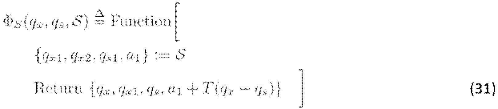

- Further, the above function Φ() clearly satisfies the
assumption 2, so that the function Φp can be determined as follows.
- Therefore, this function can be implemented in a form of the algorithm (24). A result of this implementation is as follows.

- When dynamic characteristics of a virtual object are given by a simple inertial-viscous system, the dynamic characteristics becomes as follows.


- Here, when the expression (35) is discretized, it becomes as follows.

- Solving this expression for qx(k) gives the following.

- That is, the function Γ becomes as follows.

- Next, the operation of the force control device according to the present embodiment will be described.
FIG. 5 is a flowchart illustrating the operation of the force control device according to the present embodiment. First, thecomputing unit 40 performs arithmetic processing of the admittance control based on the force applied from the outside to therobot 14 and the measured value of the force sensor 11 (S1). This arithmetic processing is as described above. As a result of the calculation, a motor torque command value for driving therobot 14 is outputted and inputted to the robot 14 (S2). Therobot 14 is driven according to the torque command value (S3). When the driving of therobot 14 finishes, the processing is terminated. When the driving (including a stopped state) continues, as a result of the driving, the position of therobot 14 and the measured value of theforce sensor 11 are outputted, and the process returns to the arithmetic processing of the admittance control in step S1. Thereafter, the same processing is repeated. - As described above, in the force control device according to the present embodiment, when the calculated torque is outside the predetermined range set previously, the position of the virtual object at the next time is determined using the algebraic loop based on the boundary value of the predetermined range and the torque command value, so that positional deviation between the virtual object and the control target is reduced, resulting in that it is possible to improve stability while improving followability.
- With respect to the force control device according to the present invention, the following experiment was performed.
FIG. 6 is a photograph of therobot 14 used in the experiment. The above-mentioned admittance control rule was implemented in the third joint of therobot 14, and the other joints were locked. Then, the behavior when the operation was performed by contacting theforce sensor 11 and the behavior when the operation was performed by contacting a link portion (a portion other than the force sensor 11) were observed. -
FIG. 7 is a diagram showing a result of an admittance control when a conventional method was used, andFIG. 8 is a diagram showing a result of an admittance control when the force control device according to the present invention was used. InFIGs. 7 and8 , measurement results are shown for the respective states as follows: - (1) to time A: operated with the
force sensor 11 held by hand; - (2) from time B to time C: a state in which a force was applied to a place outside the
force sensor 11; and - (3) From time C: a state in which a force was applied to the
force sensor 11 while the link portion was fixed by hand such that therobot 14 did not move. - As can be seen from
FIGs. 7 and8 , in the state (1), the position of therobot 14 follows the position of thevirtual object 12 well in any of the methods. In the state (2), according to the conventional method ofFIG. 7 , the position of therobot 14 and the position of thevirtual object 12 are deviated from each other. In this case, the position will tend to return to the original position like a spring when the applied force is released, which might be dangerous. On the other hand, according to the method of the present invention inFIG. 8 , the position of thevirtual object 12 follows the position of therobot 14, so that there would be no such a danger at all even when the applied force is released. In the state (3), according to the conventional method shown inFIG. 7 , only the position of thevirtual object 12 moves. In this case, therobot 14 will tend to follow the position of the far-awayvirtual object 12 when the user releases his/her hand, which might be dangerous. On the other hand, according to the method of the present application inFIG. 8 , the position of thevirtual object 12 does not move and the position of therobot 14 does not move either, so that there would be no such a danger at all. - As described above, it has been revealed that the method of the present invention has significantly improved safety as compared with the conventional method in such a situation where the torque saturation occurs.
-
- 1
- Force Control Device
- 11
- Force Sensor
- 12
- Virtual Object
- 13
- Position Controller
- 14
- Robot
- 21
- CPU
- 22
- RAM
- 23
- ROM
- 24
- Input-Output Interface
- 40
- Computing Unit
- 41
- Moving Mechanism
- 42
- Drive Unit
Claims (9)
- A force control device comprising:a position detector that detects a position of a control target;a force sensor that detects a force by which the control target is in contact with an object;a moving mechanism that movably holds the control target;a driving unit that includes a motor that uses a torque command value as an input to operate the moving mechanism; anda computing unit that determines the torque command value, whereinthe computing unit stores a virtual object having predetermined dynamic characteristics, and a position control rule, and is configured to:calculate a position at a next time, the position being calculated by simulating a motion of the virtual object when a target force exerted on the control target and a measured value of the force sensor are given to the virtual object;obtain a torque calculated when the calculated position is given to the position control rule as a target position at the next time;when the obtained torque is within a predetermined range set previously, determine the obtained torque as the torque command value to determine the calculated position as a position of the virtual object at the next time; andwhen the obtained torque is outside the predetermined range set previously, determine the position of the virtual object at the next time based on a boundary value of the predetermined range and the obtained torque.
- The force control device according to claim 1, wherein the computing unit is configured to, when the obtained torque is outside the predetermined range set previously, determine a torque on a boundary of the predetermined range and closest to the obtained torque, as the torque command value, calculate the target position at the next time when a torque command value calculated by the position controller becomes the determined torque command value, and determine the calculated target position as the position of the virtual object at the next time.
- The force control device according to claim 2, wherein the computing unit is configured to determine, in a continuous time, the torque τ by updating the position qx of the virtual object so as to satisfy


- The force control device according to claim 2, wherein the computing unit is configured to determine, at a time k in a discrete time, determine qx(k) and τ(k) so as to satisfy


- The force control device according to claim 4, wherein the function Γ is given by a function having an input-output relation as

- The force control device according to claim 4, wherein the function Φ is a function having a same input-output relation as in an algorithm as

- The force control device according to claim 4, wherein the calculation for determining qx(k) and τ(k) has a same input-output relation as in an algorithm as follows.





- A force control method performed by a computer, the method comprising:a position detecting step of detecting a position of a control target;a force detecting step of detecting a force by which the control target is in contact with an object;a computing step of computing a torque command value for a driving unit that includes a motor that uses the torque command value as an input to operate the moving mechanism; anda moving step of moving the control target based on a computation result of the computing step, wherein the computing step comprises:calculating a position at a next time, the position being calculated by simulating a motion of a virtual object when a target force exerted on the control target and a measured value of the force detecting step are given to the virtual object, using the virtual object and a position control rule that are stored in the computer, the virtual object having predetermined dynamic characteristics;obtaining a torque calculated when the calculated position is given to the position control rule as a target position at the next time;when the obtained torque is within a predetermined range set previously, determining the obtained torque as the torque command value to determine the calculated position as a position of the virtual object at the next time; andwhen the obtained torque is outside the predetermined range set previously, determining the position of the virtual object at the next time based on a boundary value of the predetermined range and the obtained torque.
- A force control program that makes a computer to function as:position detecting means for detecting a position of a control target;force detecting means for detecting a force by which the control target is in contact with an object;computing means for computing a torque command value for a driving unit that includes a motor that uses the torque command value as an input to operate the moving mechanism; andmoving control means for controlling a movement of the control target based on a computation result of the computing means, wherein the computing means:calculates a position at a next time, the position being calculated by simulating a motion of the virtual object when a target force exerted on the control target and a measured value of the force detecting step are given to the virtual object, using the virtual object and a position control rule that are stored in the computer, the virtual object having predetermined dynamic characteristics;obtains a torque calculated when the calculated position is given to the position control rule as a target position at the next time;when the obtained torque is within a predetermined range set previously, determines the obtained torque as the torque command value to determine the calculated position as a position of the virtual object at the next time; andwhen the obtained torque is outside the predetermined range set previously, determines the position of the virtual object at the next time based on a boundary value of the predetermined range and the obtained torque.
Applications Claiming Priority (2)
| Application Number | Priority Date | Filing Date | Title |
|---|---|---|---|
| JP2017136283A JP6934173B2 (en) | 2017-07-12 | 2017-07-12 | Force control device, force control method and force control program |
| PCT/JP2018/025338 WO2019013067A1 (en) | 2017-07-12 | 2018-07-04 | Force control device, force control method, and force control program |
Publications (2)
| Publication Number | Publication Date |
|---|---|
| EP3654119A1 true EP3654119A1 (en) | 2020-05-20 |
| EP3654119A4 EP3654119A4 (en) | 2021-04-07 |
Family
ID=65002553
Family Applications (1)
| Application Number | Title | Priority Date | Filing Date |
|---|---|---|---|
| EP18832753.0A Withdrawn EP3654119A4 (en) | 2017-07-12 | 2018-07-04 | FORCE CONTROL DEVICE, FORCE CONTROL PROCEDURE AND FORCE CONTROL PROGRAM |
Country Status (4)
| Country | Link |
|---|---|
| US (1) | US20200180150A1 (en) |
| EP (1) | EP3654119A4 (en) |
| JP (1) | JP6934173B2 (en) |
| WO (1) | WO2019013067A1 (en) |
Cited By (1)
| Publication number | Priority date | Publication date | Assignee | Title |
|---|---|---|---|---|
| EP4099102A4 (en) * | 2020-01-29 | 2023-06-28 | Man-Machine Synergy Effectors, Inc. | Drive unit adopting admittance control |
Families Citing this family (8)
| Publication number | Priority date | Publication date | Assignee | Title |
|---|---|---|---|---|
| CN110045604B (en) * | 2019-02-27 | 2022-03-01 | 沈阳工业大学 | Voice coil motor driven Lorentz force FTS repetitive sliding mode compound control method |
| CN111897289B (en) * | 2020-08-05 | 2022-02-18 | 上海柏楚电子科技股份有限公司 | Torque information processing method, device, equipment and medium for motor driving mechanism |
| CN112891127B (en) * | 2021-01-14 | 2022-07-26 | 东南大学 | A Mirror Rehabilitation Training Method Based on Adaptive Impedance Control |
| CN112809687B (en) * | 2021-02-08 | 2022-04-12 | 上海电气集团股份有限公司 | Simulation method, device and equipment of robot controller |
| CN113110051B (en) * | 2021-04-14 | 2022-03-04 | 南开大学 | Polishing machine manpower/position hybrid control method and system considering error constraint |
| CN114789444B (en) * | 2022-05-05 | 2022-12-16 | 山东省人工智能研究院 | Compliant human-computer contact method based on deep reinforcement learning and impedance control |
| KR102715466B1 (en) | 2022-06-16 | 2024-10-15 | 한국전자통신연구원 | System and method for precise force control of robot |
| CN115556088B (en) * | 2022-08-26 | 2024-12-06 | 遨博(北京)智能科技股份有限公司 | Control system for contact force of manipulator, manipulator and robot |
Family Cites Families (9)
| Publication number | Priority date | Publication date | Assignee | Title |
|---|---|---|---|---|
| JPS6032811B2 (en) | 1978-06-20 | 1985-07-30 | 東芝テック株式会社 | weight measuring device |
| JP2770982B2 (en) * | 1989-05-25 | 1998-07-02 | 株式会社豊田中央研究所 | Manipulator position and force coordination controller |
| JP4055090B2 (en) * | 1997-07-08 | 2008-03-05 | 株式会社安川電機 | Robot control device |
| JP2007102748A (en) | 2005-09-06 | 2007-04-19 | Nagoya Institute Of Technology | POSITION CONTROL DEVICE, POSITION CONTROL METHOD, AND POSITION CONTROL PROGRAM |
| JP2008073830A (en) * | 2006-09-25 | 2008-04-03 | Fanuc Ltd | Robot control device |
| JP4319232B2 (en) * | 2007-09-12 | 2009-08-26 | トヨタ自動車株式会社 | Power assist device and control method thereof |
| JP4997145B2 (en) * | 2008-02-29 | 2012-08-08 | トヨタ自動車株式会社 | Power assist device and control method thereof |
| JP6032811B2 (en) * | 2013-02-18 | 2016-11-30 | 国立大学法人九州大学 | Force control device and position control device using admittance control |
| US9186795B1 (en) * | 2013-06-24 | 2015-11-17 | Redwood Robotics, Inc. | Programming and execution of force-based tasks with torque-controlled robot arms |
-
2017
- 2017-07-12 JP JP2017136283A patent/JP6934173B2/en active Active
-
2018
- 2018-07-04 WO PCT/JP2018/025338 patent/WO2019013067A1/en not_active Ceased
- 2018-07-04 EP EP18832753.0A patent/EP3654119A4/en not_active Withdrawn
- 2018-07-04 US US16/629,758 patent/US20200180150A1/en not_active Abandoned
Cited By (2)
| Publication number | Priority date | Publication date | Assignee | Title |
|---|---|---|---|---|
| EP4099102A4 (en) * | 2020-01-29 | 2023-06-28 | Man-Machine Synergy Effectors, Inc. | Drive unit adopting admittance control |
| US12097618B2 (en) | 2020-01-29 | 2024-09-24 | Man-Machine Synergy Effectors, Inc. | Drive unit adopting admittance control |
Also Published As
| Publication number | Publication date |
|---|---|
| JP2019020826A (en) | 2019-02-07 |
| WO2019013067A1 (en) | 2019-01-17 |
| US20200180150A1 (en) | 2020-06-11 |
| JP6934173B2 (en) | 2021-09-15 |
| EP3654119A4 (en) | 2021-04-07 |
Similar Documents
| Publication | Publication Date | Title |
|---|---|---|
| JP6934173B2 (en) | Force control device, force control method and force control program | |
| Nemec et al. | Human robot cooperation with compliance adaptation along the motion trajectory | |
| Wu et al. | A survey of learning-based control of robotic visual servoing systems | |
| US10751874B2 (en) | Method of teaching robot and robotic arm control device | |
| Campbell | High-index differential algebraic equations | |
| JP6032811B2 (en) | Force control device and position control device using admittance control | |
| Valency et al. | Accuracy/robustness dilemma in impedance control | |
| Kikuuwe | A sliding-mode-like position controller for admittance control with bounded actuator force | |
| Wang et al. | Incremental model predictive control exploiting time-delay estimation for a robot manipulator | |
| KR102003216B1 (en) | Motor control and / or adjustment for the robot | |
| Nuño et al. | Position tracking for non-linear teleoperators with variable time delay | |
| CN112203811B (en) | Robot system and robot control method | |
| Jin et al. | Review on control strategies for cable-driven parallel robots with model uncertainties | |
| Tan et al. | A singularity-free motion control algorithm for robot manipulators—a hybrid system approach | |
| Likar et al. | Adaptation of bimanual assembly tasks using iterative learning framework | |
| Zhang et al. | Time delay compensation of a robotic arm based on multiple sensors for indirect teaching | |
| Gu et al. | Adaptive robust tracking control for hybrid models of three-dimensional bipedal robotic walking under uncertainties | |
| Sakow et al. | Unilateral hydraulic telemanipulation system for operation in machining work area | |
| Baptista et al. | Fuzzy predictive algorithms applied to real-time force control | |
| JP2004344998A (en) | Robot controller | |
| Yu et al. | Co-carrying an object by robot in cooperation with humans using visual and force sensing | |
| He et al. | Adaptive fuzzy sliding mode control for redundant manipulators with varying payload | |
| JP4587052B2 (en) | POSITION CONTROL DEVICE, POSITION CONTROL METHOD, AND POSITION CONTROL PROGRAM | |
| Zhang et al. | Com shifter and body rotator for step-by-step teleoperation of bipedal robots | |
| Smisek et al. | Naturally-transitioning rate-to-force controller robust to time delay by model-mediated teleoperation |
Legal Events
| Date | Code | Title | Description |
|---|---|---|---|
| STAA | Information on the status of an ep patent application or granted ep patent |
Free format text: STATUS: THE INTERNATIONAL PUBLICATION HAS BEEN MADE |
|
| PUAI | Public reference made under article 153(3) epc to a published international application that has entered the european phase |
Free format text: ORIGINAL CODE: 0009012 |
|
| STAA | Information on the status of an ep patent application or granted ep patent |
Free format text: STATUS: REQUEST FOR EXAMINATION WAS MADE |
|
| 17P | Request for examination filed |
Effective date: 20200110 |
|
| AK | Designated contracting states |
Kind code of ref document: A1 Designated state(s): AL AT BE BG CH CY CZ DE DK EE ES FI FR GB GR HR HU IE IS IT LI LT LU LV MC MK MT NL NO PL PT RO RS SE SI SK SM TR |
|
| AX | Request for extension of the european patent |
Extension state: BA ME |
|
| DAV | Request for validation of the european patent (deleted) | ||
| DAX | Request for extension of the european patent (deleted) | ||
| A4 | Supplementary search report drawn up and despatched |
Effective date: 20210310 |
|
| RIC1 | Information provided on ipc code assigned before grant |
Ipc: B25J 9/16 20060101AFI20210303BHEP Ipc: G05B 17/02 20060101ALI20210303BHEP |
|
| STAA | Information on the status of an ep patent application or granted ep patent |
Free format text: STATUS: THE APPLICATION HAS BEEN WITHDRAWN |
|
| 18W | Application withdrawn |
Effective date: 20220704 |