EP3654008A1 - Method for detecting a water penetration in a housing, electronic circuit for implementing the method, housing with the electronic circuit and vehicle with the housing - Google Patents
Method for detecting a water penetration in a housing, electronic circuit for implementing the method, housing with the electronic circuit and vehicle with the housing Download PDFInfo
- Publication number
- EP3654008A1 EP3654008A1 EP19204791.8A EP19204791A EP3654008A1 EP 3654008 A1 EP3654008 A1 EP 3654008A1 EP 19204791 A EP19204791 A EP 19204791A EP 3654008 A1 EP3654008 A1 EP 3654008A1
- Authority
- EP
- European Patent Office
- Prior art keywords
- housing
- water ingress
- detection
- detected
- water
- Prior art date
- Legal status (The legal status is an assumption and is not a legal conclusion. Google has not performed a legal analysis and makes no representation as to the accuracy of the status listed.)
- Granted
Links
- XLYOFNOQVPJJNP-UHFFFAOYSA-N water Substances O XLYOFNOQVPJJNP-UHFFFAOYSA-N 0.000 title claims abstract description 90
- 238000000034 method Methods 0.000 title claims abstract description 30
- 230000035515 penetration Effects 0.000 title description 2
- 238000001514 detection method Methods 0.000 claims abstract description 22
- 230000006870 function Effects 0.000 claims description 28
- 230000008859 change Effects 0.000 claims description 19
- 239000002274 desiccant Substances 0.000 claims description 6
- 230000003068 static effect Effects 0.000 claims description 6
- 230000006978 adaptation Effects 0.000 claims description 4
- 230000005494 condensation Effects 0.000 description 6
- 238000009833 condensation Methods 0.000 description 6
- 238000010586 diagram Methods 0.000 description 6
- 229920000642 polymer Polymers 0.000 description 6
- 230000008020 evaporation Effects 0.000 description 5
- 238000001704 evaporation Methods 0.000 description 5
- 230000001419 dependent effect Effects 0.000 description 4
- 238000007599 discharging Methods 0.000 description 4
- 230000007774 longterm Effects 0.000 description 4
- 230000008901 benefit Effects 0.000 description 3
- 239000000463 material Substances 0.000 description 3
- 230000008439 repair process Effects 0.000 description 3
- 230000000694 effects Effects 0.000 description 2
- 230000009931 harmful effect Effects 0.000 description 2
- VYPSYNLAJGMNEJ-UHFFFAOYSA-N Silicium dioxide Chemical compound O=[Si]=O VYPSYNLAJGMNEJ-UHFFFAOYSA-N 0.000 description 1
- 229910021536 Zeolite Inorganic materials 0.000 description 1
- 230000015572 biosynthetic process Effects 0.000 description 1
- 238000004140 cleaning Methods 0.000 description 1
- HNPSIPDUKPIQMN-UHFFFAOYSA-N dioxosilane;oxo(oxoalumanyloxy)alumane Chemical compound O=[Si]=O.O=[Al]O[Al]=O HNPSIPDUKPIQMN-UHFFFAOYSA-N 0.000 description 1
- 230000005484 gravity Effects 0.000 description 1
- 238000012423 maintenance Methods 0.000 description 1
- 239000011159 matrix material Substances 0.000 description 1
- 230000008018 melting Effects 0.000 description 1
- 238000002844 melting Methods 0.000 description 1
- 239000012528 membrane Substances 0.000 description 1
- 239000000203 mixture Substances 0.000 description 1
- 230000008569 process Effects 0.000 description 1
- 229920006395 saturated elastomer Polymers 0.000 description 1
- 238000007789 sealing Methods 0.000 description 1
- 230000035939 shock Effects 0.000 description 1
- 239000000741 silica gel Substances 0.000 description 1
- 229910002027 silica gel Inorganic materials 0.000 description 1
- 239000004575 stone Substances 0.000 description 1
- 239000000126 substance Substances 0.000 description 1
- 239000010457 zeolite Substances 0.000 description 1
Images


Classifications
-
- G—PHYSICS
- G01—MEASURING; TESTING
- G01M—TESTING STATIC OR DYNAMIC BALANCE OF MACHINES OR STRUCTURES; TESTING OF STRUCTURES OR APPARATUS, NOT OTHERWISE PROVIDED FOR
- G01M3/00—Investigating fluid-tightness of structures
- G01M3/02—Investigating fluid-tightness of structures by using fluid or vacuum
- G01M3/04—Investigating fluid-tightness of structures by using fluid or vacuum by detecting the presence of fluid at the leakage point
- G01M3/16—Investigating fluid-tightness of structures by using fluid or vacuum by detecting the presence of fluid at the leakage point using electric detection means
- G01M3/18—Investigating fluid-tightness of structures by using fluid or vacuum by detecting the presence of fluid at the leakage point using electric detection means for pipes, cables or tubes; for pipe joints or seals; for valves; for welds; for containers, e.g. radiators
- G01M3/183—Investigating fluid-tightness of structures by using fluid or vacuum by detecting the presence of fluid at the leakage point using electric detection means for pipes, cables or tubes; for pipe joints or seals; for valves; for welds; for containers, e.g. radiators for pipe joints or seals
-
- B—PERFORMING OPERATIONS; TRANSPORTING
- B62—LAND VEHICLES FOR TRAVELLING OTHERWISE THAN ON RAILS
- B62J—CYCLE SADDLES OR SEATS; AUXILIARY DEVICES OR ACCESSORIES SPECIALLY ADAPTED TO CYCLES AND NOT OTHERWISE PROVIDED FOR, e.g. ARTICLE CARRIERS OR CYCLE PROTECTORS
- B62J45/00—Electrical equipment arrangements specially adapted for use as accessories on cycles, not otherwise provided for
- B62J45/40—Sensor arrangements; Mounting thereof
- B62J45/41—Sensor arrangements; Mounting thereof characterised by the type of sensor
-
- B—PERFORMING OPERATIONS; TRANSPORTING
- B62—LAND VEHICLES FOR TRAVELLING OTHERWISE THAN ON RAILS
- B62M—RIDER PROPULSION OF WHEELED VEHICLES OR SLEDGES; POWERED PROPULSION OF SLEDGES OR SINGLE-TRACK CYCLES; TRANSMISSIONS SPECIALLY ADAPTED FOR SUCH VEHICLES
- B62M6/00—Rider propulsion of wheeled vehicles with additional source of power, e.g. combustion engine or electric motor
- B62M6/40—Rider propelled cycles with auxiliary electric motor
- B62M6/45—Control or actuating devices therefor
- B62M6/50—Control or actuating devices therefor characterised by detectors or sensors, or arrangement thereof
-
- G—PHYSICS
- G01—MEASURING; TESTING
- G01M—TESTING STATIC OR DYNAMIC BALANCE OF MACHINES OR STRUCTURES; TESTING OF STRUCTURES OR APPARATUS, NOT OTHERWISE PROVIDED FOR
- G01M3/00—Investigating fluid-tightness of structures
- G01M3/002—Investigating fluid-tightness of structures by using thermal means
-
- G—PHYSICS
- G01—MEASURING; TESTING
- G01M—TESTING STATIC OR DYNAMIC BALANCE OF MACHINES OR STRUCTURES; TESTING OF STRUCTURES OR APPARATUS, NOT OTHERWISE PROVIDED FOR
- G01M3/00—Investigating fluid-tightness of structures
- G01M3/02—Investigating fluid-tightness of structures by using fluid or vacuum
- G01M3/04—Investigating fluid-tightness of structures by using fluid or vacuum by detecting the presence of fluid at the leakage point
- G01M3/16—Investigating fluid-tightness of structures by using fluid or vacuum by detecting the presence of fluid at the leakage point using electric detection means
- G01M3/18—Investigating fluid-tightness of structures by using fluid or vacuum by detecting the presence of fluid at the leakage point using electric detection means for pipes, cables or tubes; for pipe joints or seals; for valves; for welds; for containers, e.g. radiators
- G01M3/186—Investigating fluid-tightness of structures by using fluid or vacuum by detecting the presence of fluid at the leakage point using electric detection means for pipes, cables or tubes; for pipe joints or seals; for valves; for welds; for containers, e.g. radiators for containers, e.g. radiators
-
- H—ELECTRICITY
- H01—ELECTRIC ELEMENTS
- H01M—PROCESSES OR MEANS, e.g. BATTERIES, FOR THE DIRECT CONVERSION OF CHEMICAL ENERGY INTO ELECTRICAL ENERGY
- H01M10/00—Secondary cells; Manufacture thereof
- H01M10/42—Methods or arrangements for servicing or maintenance of secondary cells or secondary half-cells
- H01M10/44—Methods for charging or discharging
-
- H—ELECTRICITY
- H01—ELECTRIC ELEMENTS
- H01M—PROCESSES OR MEANS, e.g. BATTERIES, FOR THE DIRECT CONVERSION OF CHEMICAL ENERGY INTO ELECTRICAL ENERGY
- H01M10/00—Secondary cells; Manufacture thereof
- H01M10/42—Methods or arrangements for servicing or maintenance of secondary cells or secondary half-cells
- H01M10/48—Accumulators combined with arrangements for measuring, testing or indicating the condition of cells, e.g. the level or density of the electrolyte
-
- G—PHYSICS
- G01—MEASURING; TESTING
- G01M—TESTING STATIC OR DYNAMIC BALANCE OF MACHINES OR STRUCTURES; TESTING OF STRUCTURES OR APPARATUS, NOT OTHERWISE PROVIDED FOR
- G01M3/00—Investigating fluid-tightness of structures
- G01M3/02—Investigating fluid-tightness of structures by using fluid or vacuum
- G01M3/26—Investigating fluid-tightness of structures by using fluid or vacuum by measuring rate of loss or gain of fluid, e.g. by pressure-responsive devices, by flow detectors
- G01M3/32—Investigating fluid-tightness of structures by using fluid or vacuum by measuring rate of loss or gain of fluid, e.g. by pressure-responsive devices, by flow detectors for containers, e.g. radiators
- G01M3/3236—Investigating fluid-tightness of structures by using fluid or vacuum by measuring rate of loss or gain of fluid, e.g. by pressure-responsive devices, by flow detectors for containers, e.g. radiators by monitoring the interior space of the containers
-
- G—PHYSICS
- G08—SIGNALLING
- G08B—SIGNALLING OR CALLING SYSTEMS; ORDER TELEGRAPHS; ALARM SYSTEMS
- G08B21/00—Alarms responsive to a single specified undesired or abnormal condition and not otherwise provided for
- G08B21/18—Status alarms
- G08B21/20—Status alarms responsive to moisture
-
- H—ELECTRICITY
- H01—ELECTRIC ELEMENTS
- H01M—PROCESSES OR MEANS, e.g. BATTERIES, FOR THE DIRECT CONVERSION OF CHEMICAL ENERGY INTO ELECTRICAL ENERGY
- H01M2220/00—Batteries for particular applications
- H01M2220/20—Batteries in motive systems, e.g. vehicle, ship, plane
-
- Y—GENERAL TAGGING OF NEW TECHNOLOGICAL DEVELOPMENTS; GENERAL TAGGING OF CROSS-SECTIONAL TECHNOLOGIES SPANNING OVER SEVERAL SECTIONS OF THE IPC; TECHNICAL SUBJECTS COVERED BY FORMER USPC CROSS-REFERENCE ART COLLECTIONS [XRACs] AND DIGESTS
- Y02—TECHNOLOGIES OR APPLICATIONS FOR MITIGATION OR ADAPTATION AGAINST CLIMATE CHANGE
- Y02E—REDUCTION OF GREENHOUSE GAS [GHG] EMISSIONS, RELATED TO ENERGY GENERATION, TRANSMISSION OR DISTRIBUTION
- Y02E60/00—Enabling technologies; Technologies with a potential or indirect contribution to GHG emissions mitigation
- Y02E60/10—Energy storage using batteries
Definitions
- An absolute air humidity ⁇ is the water vapor mass m W contained in an air volume V according to equation (1), which is usually specified in the unit g / m 3 .
- the air humidity ⁇ can alternatively be described as the ratio of the partial pressure of the water vapor e W to the product of the individual gas constant of the water R W and the absolute temperature T.
- a relative air humidity ⁇ is a ratio of the absolute air humidity ⁇ to the maximum possible mass of water vapor ⁇ max in the air or the ratio of the partial pressure of the water vapor e W to its saturation vapor pressure e sat according to equation (2).
- the relative air humidity ⁇ can be detected or measured by means of a moisture sensor, for example by absorbing water within a porous polymer matrix, which changes a dielectric constant.
- the saturation vapor pressure e sat is temperature-dependent and can be determined, for example, using the Magnus formula, see equation (3), where C1, C2 and C3 are temperature-dependent constants.
- the dew point denotes a temperature of a saturated gas mixture in an equilibrium state, that is, at which the condensation and evaporation of the moist component are balanced. At temperatures T less than the dew point ⁇ , condensation forms.
- the dew point ⁇ is dependent on the partial pressure of the water vapor e W according to equation (4), C1, C2 and C3 being the temperature-dependent constants.
- ⁇ e W C. 3rd ⁇ ln e W C. 1 C. 2nd - ln e W C. 1
- Housings for electronic components are normally sealed or sealed by means of polymer seals against water ingress from the surroundings of the housing.
- the air enclosed in an interior of a housing for electronic components is typically dry or has a low absolute atmospheric humidity and typically a temperature between ⁇ 30 ° C. and 80 ° C., in particular between ⁇ 20 ° C. and 50 ° C.
- the trapped air normally has an unsaturated state, which is why water in the interior of the housing is essentially present as water vapor in the entire temperature range of an application, for example Plastic parts of the housing can also absorb or bind water and / or desorb.
- the dew point ⁇ of the atmosphere in an interior of a housing from an electrical circuit is therefore normally low, thereby avoiding condensate formation which is harmful to the electronic components.
- the font DE 102 49 370 A1 discloses a housing of a control device with a moisture sensor for detecting the penetration of moisture.
- the object of the present invention is to improve the detection of water ingress in a housing.
- the present invention relates to a method for detecting water ingress into an interior of a housing which is sealed off from the surroundings.
- the sealed housing advantageously has at least one electrical circuit in the interior, in particular for controlling a vehicle, advantageously an electric bicycle as a vehicle, and / or a power source, in particular for providing energy for driving the vehicle or electric bicycle.
- the sealed housing preferably comprises an electrical interface between the interior and an outside of the housing.
- the method according to the invention has a detection of a temperature in the interior of the housing.
- the temperature is preferably recorded by means of a temperature sensor which is arranged in the interior.
- a relative air humidity is recorded in the interior of the housing.
- the relative air humidity is preferably recorded by means of a humidity sensor, which is also arranged in the interior. Furthermore, a detection of water entry into the housing is then carried out as a function of the detected temperature and the detected relative air humidity.
- the advantage of the method is that an absolute humidity and / or a dew point of the air in the interior is determined, for example, if a threshold value is exceeded, the water ingress is recognized.
- a change over time in the absolute and / or relative humidity and / or the dew point of the air in the interior or the balance between condensation and evaporation of the air in the interior is advantageously determined and compared with a static or advantageously dynamic threshold value, as a result of which the water ingress is recognized quickly .
- This method can also advantageously detect the entry of very small amounts of water, since the equilibrium shift between condensation and evaporation of the air takes place even in the case of small amounts in the interior of a housing.
- the detection of water ingress is advantageously made possible by means of two sensors, that is to say the temperature sensor and the humidity sensor, the two sensors being arranged in a manner protected from, for example, chemical and / or mechanical effects in the interior of the housing.
- the determination of the water entry is carried out as a function of a difference between the detected temperature and a dew point determined as a function of the detected relative air humidity and the detected temperature.
- the equilibrium between condensation and evaporation advantageously changes to determine the water entry, as a result of which, in particular, the dew point rises.
- This difference between the recorded temperature and a dew point determined as a function of the recorded temperature and the recorded relative air humidity represents a current temperature difference until a condensate is formed.
- the difference or this temperature difference has proven empirically to be a reliable measure of quality for the detection of water ingress.
- the water ingress is recognized as a function of a rate of change in the difference between the detected temperature and the determined dew point.
- the consideration of the rate of change of the difference has proven empirically to be a quick and very reliable measure of quality for the detection of water ingress.
- the water ingress is recognized when the difference and / or the rate of change of the difference each exceed a static or dynamic threshold value.
- the threshold value is preferably dynamic.
- water entry information is displayed to a user as a function of the detection of the water entry, in particular by means of a display of an electric bicycle.
- a user is advantageously informed of a detected water ingress.
- an electrical charging or discharging current of a current source is adjusted as a function of the detected water inlet, the current source being arranged in the interior of the housing.
- the power source is in particular a battery, preferably a battery of an electric bicycle. This adaptation can advantageously represent a shutdown of the current flow. By adapting the charging or discharging current, damage to the battery and / or other electrical components and in particular a short circuit are advantageously avoided.
- a fault code is stored in an electronic memory as a function of the water ingress detected.
- a service interval is preferably changed as a function of the detected water ingress, the service interval being advantageously displayed to a driver of a vehicle that has the housing, in particular an electric bicycle.
- the user or driver of the electric bicycle is advantageously stimulated to have the housing repaired by a specialist.
- a service appointment is automatically created as a function of the detected water ingress by means of a radio link to a database of a server device and displayed or suggested to a user of the housing or a driver on a display device, the user advantageously rejecting this service appointment by input using an input device , confirm or move.
- the radio connection to the database of the server device transmits user data and the input data to the server device, the server device preferably sending the service appointment to a repair workshop. This advantageously reacts immediately to water ingress, so that medium-term and long-term damage caused by water ingress is avoided.
- a desiccant is released as a function of the water ingress detected in the interior of the housing, for example a silica gel and / or a zeolite is released.
- the desiccant advantageously at least reduces the possible harmful effects of water entry. This release can take place, for example, by opening a closure device, for example a mechanically prestressed flap and / or a melting membrane that opens when a current flows.
- the invention also relates to an electronic circuit for carrying out the method for detecting the entry of water.
- the invention further relates to a housing with this electronic circuit, the housing being in particular a housing of a display of a battery or a drive unit of a vehicle.
- the invention also relates to a vehicle with at least this housing, the vehicle being in particular an electric bicycle.
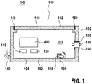
- a housing 100 is shown, for example a drive unit 230 of an electric bicycle.
- the housing 100 has a humidity sensor 110 and a temperature sensor 120 in an interior 101.
- the housing 100 further comprises an electronic circuit 400 for carrying out a method according to the invention.
- the electronic circuit 400 can advantageously also be set up to control an electric motor of an electric bicycle for driving the electric bicycle.
- Electrical interfaces 130 are also shown on an outer wall 102 of the housing 100.
- the housing 100 has display means 140, for example LED elements.
- the housing 100 is sealed against ingress of water from the environment 190 by means of at least one polymer seal 150.
- the housing 100 comprises, for example, a cover 103 and a base housing 104, polymer seals 150, for example, being arranged between the cover 103 and the base housing 104 and at the electrical interfaces 130.
- the housing 100 can show damage or leaks due to a shock load or long-term material fatigue, for example the polymer seals 150, as a result of which short-term or long-term water ingress occurs.
- an additional closed space 198 with a desiccant 199 is optionally provided in the housing 100, the space 198 being opened in the event of water inlet being detected and the desiccant 199 being released.
- the housing 100 comprises a pressure compensation element (in Figure 1 not shown), which balances the atmospheric pressure between the interior 101 of the housing and the environment 190.
- the optional pressure compensation element can advantageously improve a sealing effect of the polymer seals 150.
- FIG. 2 An electric bicycle 200 comprising a battery 220, a display 210 and a drive unit 230, which can comprise, for example, an electronic circuit or a control unit, is shown.
- the battery 220 and / or the display 210 and / or the drive unit 230 have a housing 100 according to the invention.
- the housing 100 can alternatively be used, for example, in other technical applications, for example the housing 100 can comprise a safety-relevant electrical circuit of a vehicle.
- the housing is a housing for power electronics of an electric vehicle Housing 100 of a steering system control of a vehicle, a housing 100 of a battery or a battery management system of a vehicle or a housing of a power tool.
- FIG. 3 A flow chart of the method for detecting 330 water ingress into the housing 100 is shown.
- the method has a step 310 in which a current temperature in the interior 101 of the housing 100 is detected.
- step 320 a relative humidity of the air in the interior 101 of the housing 100 is detected.
- step 330 water ingress is recognized as a function of the detected temperature and the detected relative air humidity.
- Detection 330 of water ingress occurs in particular as a function of a determined difference ⁇ between the detected temperature T and a dew point ⁇ determined as a function of the detected relative atmospheric humidity ⁇ and as a function of the detected temperature T.
- the entry of water occurs, for example, when this determined difference ⁇ falls below or exceeds a threshold value.
- the detection 330 of water ingress occurs as a function of a rate of change ⁇ of the difference ⁇ determined, in particular if the rate of change ⁇ of the difference ⁇ exceeds a static or dynamic threshold value S.
- the threshold value S is preferably dynamic.
- the threshold value S is advantageously determined as a function of one or more statistical indicators of the rate of change ⁇ in time of the difference ⁇ , for example an average value and / or a standard deviation and / or a multiple of the standard deviation.
- the statistical key figures of the rate of change ⁇ in time of the difference ⁇ are determined in a time period before the current point in time or in a sliding manner.
- step 340 water entry information is displayed to a user depending on the detection 330 of the water entry, for example by means of the display means 140.
- an optional adaptation 350 of an electrical charging or discharging current of a current source or battery, which is arranged in the interior of the housing 100 is carried out depending on the detected water ingress.
- the adaptation 350 of an electrical charging or discharging current can be carried out by means of an electrical switch until the current source is switched off.
- an optional storage 360 of an error code in an electronic Storage can be carried out as a function of the detected water entry, the electronic storage advantageously also being arranged in the housing 100 and being able to be read out, for example, by means of the interface 130.
- a change 370 of a service interval of a vehicle is optionally carried out depending on the water ingress detected in step 330.
- a service appointment is created in optional step 380 as a function of the detected water ingress by means of a radio connection to a server device and is displayed in particular to the user.
- a release 390 of a desiccant 199 can also be provided in the interior 101 of the housing 100 as a function of the detected water ingress.
- FIGs 4a and 4b is in each case a diagram of the time profile of the difference ⁇ between the current temperature T determined in step 310 and the function of the relative air humidity Huawei determined in step 320 and as a function of the temperature T determined in step 310 as a function of the temperature T determined in step 310 shown.
- the determined difference ⁇ has the unit [K].
- the time is given in hours or [h].
- the course of the determined difference ⁇ shows natural fluctuations or a noise, but no strong deviations, since there is no water ingress.
- water 401 enters housing 100, as a result of which the determined difference ⁇ drops sharply.
- the entry of water can consequently be reliably identified by this determined difference ⁇ as soon as, for example, the determined difference ⁇ exceeds or falls below a static or dynamic threshold value.
- the determined difference ⁇ drops significantly, for example, even if only a small amount of water enters the housing 100, since even a small amount of water always causes a shift in equilibrium between the evaporation and the condensation.
- FIG. 5a and 5b is a diagram of the time course of the rate of change A of the difference ⁇ between the current temperature T determined in step 310 and the relative air humidity ⁇ determined in step 320 and the current temperature recorded in step 310 T determined dew point ⁇ shown.
- the Figure 5a corresponds to the Figure 4a (ie no water entry) and the Figure 5b corresponds to the Figure 4b (ie with water entry).
- the determined rate of change ⁇ has the unit [K / h].
- the time is given in hours h.
- the course of the determined change rate ⁇ shows in Figure 5a Fluctuations or noise, but no major deviations, since there is no water ingress.
Landscapes
- Engineering & Computer Science (AREA)
- Chemical & Material Sciences (AREA)
- General Physics & Mathematics (AREA)
- Physics & Mathematics (AREA)
- Electrochemistry (AREA)
- Chemical Kinetics & Catalysis (AREA)
- Manufacturing & Machinery (AREA)
- General Chemical & Material Sciences (AREA)
- Mechanical Engineering (AREA)
- Combustion & Propulsion (AREA)
- Transportation (AREA)
- Casings For Electric Apparatus (AREA)
- Electric Propulsion And Braking For Vehicles (AREA)
Abstract
Verfahren zur Erkennung (330) eines Wassereintritts in einem Innenraum (101) eines gegenüber einer Umgebung (190) abgedichteten Gehäuses (100), aufweisend die folgenden Schritte: Erfassung (310) einer Temperatur (T) der Luft in dem Innenraum (101); Erfassung (320) einer relativen Luftfeuchte (ϕ) im Innenraum (101); und Erkennung (330) eines Wassereintritts in Abhängigkeit der erfassten Temperatur (T) und der erfassten relativen Luftfeuchte (ϕ).A method for detecting (330) water ingress in an interior (101) of a housing (100) sealed against an environment (190), comprising the following steps: detecting (310) a temperature (T) of the air in the interior (101); Detection (320) of a relative air humidity (ϕ) in the interior (101); and detection (330) of water ingress as a function of the detected temperature (T) and the detected relative air humidity (ϕ).
Description
Die vorliegende Erfindung betrifft ein Verfahren zur Erkennung eines Wassereintritts in einem Gehäuse in Abhängigkeit einer erfassten Temperatur und einer erfassten relativen Feuchtigkeit. Die Erfindung betrifft auch eine elektronische Schaltung zur Durchführung des Verfahrens sowie ein Gehäuse mit der elektronischen Schaltung und ein Fahrzeug mit dem Gehäuse, insbesondere ein Elektrofahrrad.The present invention relates to a method for detecting water ingress in a housing as a function of a detected temperature and a detected relative humidity. The invention also relates to an electronic circuit for carrying out the method and a housing with the electronic circuit and a vehicle with the housing, in particular an electric bicycle.
Eine absolute Luftfeuchtigkeit ρ ist die in einem Luftvolumen V enthaltene Wasserdampfmasse mW gemäß Gleichung (1), welche üblicherweise in der Einheit g/m3 angegeben wird. Die Luftfeuchtigkeit ρ kann gemäß der idealen Gasgleichung alternativ als Verhältnis des Partialdrucks des Wasserdampfes eW zu dem Produkt aus individueller Gaskonstante des Wassers RW und absoluter Temperatur T beschrieben werden. ![]()
![]()
Eine relative Luftfeuchtigkeit ϕ ist ein Verhältnis der absoluten Luftfeuchtigkeit ρ zur maximal möglichen Masse an Wasserdampf ρ max in der Luft beziehungsweise das Verhältnis des Partialdrucks des Wasserdampfes eW zu dessen Sättigungsdampfdruck esat nach Gleichung (2). Die relative Luftfeuchtigkeit ϕ kann mittels eines Feuchtesensors erfasst beziehungsweise gemessen werden, beispielsweise durch Absorption von Wasser innerhalb einer porösen Polymermatrix, wodurch eine Dielektrizitätskonstante verändert wird. Der Sättigungsdampfdruck esat ist temperaturabhängig und kann beispielsweise mit Hilfe der Magnus-Formel bestimmt werden, siehe Gleichung (3), wobei C1, C2 und C3 temperaturabhängige Konstanten sind. ![]()
![]()
![]()
![]()
Der Taupunkt bezeichnet eine Temperatur eines gesättigten Gasgemisches in einem Gleichgewichtszustand, das heißt bei welchem sich Kondensation und Verdunstung des feuchten Bestandteils ausgleichen. Bei Temperaturen T kleiner dem Taupunkt τ kommt es zur Kondensatbildung. Der Taupunkt τ ist abhängig von dem Partialdruck des Wasserdampfes eW gemäß Gleichung (4), wobei C1, C2 und C3 die temperaturabhängigen Konstanten sind. ![]()
![]()
Gehäuse für elektronische Komponenten, insbesondere elektronische Schaltungen und Batterien, werden normalerweise mittels Polymerdichtungen gegen einen Wassereintritt aus der Umgebung des Gehäuses dicht verschlossen beziehungsweise abgedichtet. Die in einem Innenraum eines Gehäuses für elektronische Komponenten eingeschlossene Luft ist typischerweise trocken beziehungsweise weist eine niedrige absolute Luftfeuchtigkeit und typischerweise eine Temperatur zwischen - 30 °C und 80 °C, insbesondere zwischen -20 °C und 50 °C, auf. Mit anderen Worten weist normalerweise die eingeschlossene Luft einen ungesättigten Zustand auf, weshalb Wasser im Innenraum des Gehäuses im gesamten Temperaturbereich einer Anwendung im Wesentlichen als Wasserdampf vorliegt, wobei beispielsweise Kunststoffanteile des Gehäuses zusätzlich auch Wasser absorbieren bzw. binden und/oder desorbieren können. Der Taupunkt τ der Atmosphäre in einem Innenraum eines Gehäuses von einer elektrischen Schaltung ist normalerweise folglich niedrig, wodurch eine für die elektronischen Komponenten schädliche Kondensatbildung vermieden wird.Housings for electronic components, in particular electronic circuits and batteries, are normally sealed or sealed by means of polymer seals against water ingress from the surroundings of the housing. The air enclosed in an interior of a housing for electronic components is typically dry or has a low absolute atmospheric humidity and typically a temperature between −30 ° C. and 80 ° C., in particular between −20 ° C. and 50 ° C. In other words, the trapped air normally has an unsaturated state, which is why water in the interior of the housing is essentially present as water vapor in the entire temperature range of an application, for example Plastic parts of the housing can also absorb or bind water and / or desorb. The dew point τ of the atmosphere in an interior of a housing from an electrical circuit is therefore normally low, thereby avoiding condensate formation which is harmful to the electronic components.
Durch beispielsweise einen Fehlgebrauch bei der Reinigung, insbesondere durch eine Anwendung von Hochdruck-Reinigern im Bereich der Dichtungen, durch mechanische Beschädigungen und/oder Materialermüdung kann allerdings ein Wassereintritt in den Innenraum des Gehäuses erfolgen.Misuse during cleaning, in particular due to the use of high-pressure cleaners in the area of the seals, mechanical damage and / or material fatigue can, however, cause water to enter the interior of the housing.
Eine elektrische Schaltung zur Steuerung eines Elektromotors eines Elektrofahrrads ist beispielsweise in einem Gehäuse einer Antriebseinheit an der Kurbelwelle des Elektrofahrrads angeordnet, wobei das Gehäuse vorteilhafterweise zusätzlich den Elektromotor umfasst. Die Anordnung des Elektromotors beziehungsweise des Gehäuses im Bereich der Kurbelwelle hat einige technische Vorteile, beispielsweise bezüglich einer Gewichtsverteilung und/oder des Schwerpunktes des Elektrofahrrad beziehungsweise bezüglich des Fahrgefühls für den Fahrer. Allerdings ist ein Wassereintritt in das Gehäuse der Antriebseinheit durch Spritzwasser während der Fahrt und/oder durch eine mechanische Beschädigung des Gehäuses durch Steinschlag, Bodenberührung oder ähnliches an dieser Anbauposition an der Kurbelwelle wahrscheinlicher als beispielsweise bei einer Anordnung des Antriebsmotors an einer Radnabe. Des Weiteren kann eine Materialermüdung durch einen ungünstigen Stellplatz eines Elektrofahrrads beschleunigt werden. Die Dichtigkeitsanforderungen an beispielsweise eine Antriebseinheit eines Elektrofahrrads sind folglich hoch, wobei durch eine Reparatur nach einer schnellen Erkennung eines Wassereintritts mittel- und langfristige Schädigungen der Antriebseinheit vermieden werden.An electrical circuit for controlling an electric motor of an electric bicycle is arranged, for example, in a housing of a drive unit on the crankshaft of the electric bicycle, the housing advantageously additionally comprising the electric motor. The arrangement of the electric motor or the housing in the area of the crankshaft has some technical advantages, for example with regard to a weight distribution and / or the center of gravity of the electric bike or with regard to the driving experience for the driver. However, water ingress into the housing of the drive unit due to splash water while driving and / or due to mechanical damage to the housing due to stone chips, ground contact or the like at this mounting position on the crankshaft is more likely than, for example, if the drive motor is arranged on a wheel hub. Furthermore, material fatigue can be accelerated due to an unfavorable parking space for an electric bicycle. The tightness requirements for, for example, a drive unit of an electric bicycle are consequently high, with medium and long-term damage to the drive unit being avoided by repairs after rapid detection of water ingress.
Die Schrift
Das Dokument
Die Aufgabe der vorliegenden Erfindung ist es eine Erkennung eines Wassereintritts in einem Gehäuse zu verbessern.The object of the present invention is to improve the detection of water ingress in a housing.
Die vorstehende Aufgabe wird gemäß der unabhängigen Ansprüche 1, 11, 12 und 13 gelöst.The above object is achieved according to
Die vorliegende Erfindung betrifft ein Verfahren zur Erkennung eines Wassereintritts in einen Innenraum eines gegenüber einer Umgebung abgedichteten Gehäuses. Das abgedichtete Gehäuse weist vorteilhafterweise in dem Innenraum mindestens eine elektrische Schaltung, insbesondere zur Steuerung eines Fahrzeugs, vorteilhafterweise eines Elektrofahrrads als Fahrzeug, und/oder eine Stromquelle, insbesondere zur Bereitstellung einer Energie zum Antrieb des Fahrzeugs beziehungsweise Elektrofahrrads, auf. Ferner umfasst das abgedichtete Gehäuse vorzugsweise eine elektrische Schnittstelle zwischen dem Innenraum und einer Außenseite des Gehäuses. Das erfindungsgemäße Verfahren weist eine Erfassung einer Temperatur in dem Innenraum des Gehäuses auf. Die Temperaturerfassung erfolgt bevorzugt mittels eines Temperatursensors, welcher in dem Innenraum angeordnet ist. In einem weiteren Schritt wird eine relative Luftfeuchte in dem Innenraum des Gehäuses erfasst. Die Erfassung der relativen Luftfeuchte erfolgt bevorzugt mittels eines Feuchtesensors, welcher ebenfalls in dem Innenraum angeordnet ist. Ferner wird anschließend eine Erkennung eines Wassereintritts in das Gehäuse in Abhängigkeit der erfassten Temperatur und der erfassten relativen Luftfeuchte durchgeführt. Durch das Verfahren entsteht der Vorteil das eine absolute Feuchte und/oder ein Taupunkt der Luft im Innenraum ermittelt wird, wobei beispielsweise bei einer Überschreitung eines Schwellenwertes der Wassereintritt erkannt wird. Vorteilhafterweise wird eine zeitliche Änderung der absoluten und/oder relativen Feuchte und/oder des Taupunktes der Luft im Innenraum beziehungsweise des Gleichgewichts zwischen Kondensation und Verdunstung der Luft im Innenraum ermittelt und mit einem statischen oder vorteilhafterweise dynamischen Schwellenwert verglichen, wodurch eine schnelle Erkennung des Wassereintritts erfolgt. Durch dieses Verfahren kann auch ein Eintritt sehr kleiner Wassermengen vorteilhafterweise erkannt werden, da die Gleichgewichtsverschiebung zwischen Kondensation und Verdunstung der Luft auch bei kleinen Mengen in dem Innenraum eines Gehäuses erfolgt. Durch dieses Verfahren wird vorteilhafterweise die Erkennung eines Wassereintritts mittels zweier Sensoren, das heißt dem Temperatursensor und dem Feuchtesensor, ermöglicht, wobei die zwei Sensoren vor beispielsweise chemischen und/oder mechanischen Einwirkungen im Innenraum des Gehäuses geschützt angeordnet sind.The present invention relates to a method for detecting water ingress into an interior of a housing which is sealed off from the surroundings. The sealed housing advantageously has at least one electrical circuit in the interior, in particular for controlling a vehicle, advantageously an electric bicycle as a vehicle, and / or a power source, in particular for providing energy for driving the vehicle or electric bicycle. Furthermore, the sealed housing preferably comprises an electrical interface between the interior and an outside of the housing. The method according to the invention has a detection of a temperature in the interior of the housing. The temperature is preferably recorded by means of a temperature sensor which is arranged in the interior. In a further step, a relative air humidity is recorded in the interior of the housing. The relative air humidity is preferably recorded by means of a humidity sensor, which is also arranged in the interior. Furthermore, a detection of water entry into the housing is then carried out as a function of the detected temperature and the detected relative air humidity. The advantage of the method is that an absolute humidity and / or a dew point of the air in the interior is determined, for example, if a threshold value is exceeded, the water ingress is recognized. A change over time in the absolute and / or relative humidity and / or the dew point of the air in the interior or the balance between condensation and evaporation of the air in the interior is advantageously determined and compared with a static or advantageously dynamic threshold value, as a result of which the water ingress is recognized quickly . This method can also advantageously detect the entry of very small amounts of water, since the equilibrium shift between condensation and evaporation of the air takes place even in the case of small amounts in the interior of a housing. Through this procedure the detection of water ingress is advantageously made possible by means of two sensors, that is to say the temperature sensor and the humidity sensor, the two sensors being arranged in a manner protected from, for example, chemical and / or mechanical effects in the interior of the housing.
In einer bevorzugten Weiterführung wird die Ermittlung des Wassereintritts in Abhängigkeit einer Differenz zwischen der erfassten Temperatur und eines in Abhängigkeit der erfassten relativen Luftfeuchte und der erfassten Temperatur ermittelten Taupunktes durchgeführt. Bei einem Eintritt von Wasser ändert sich für die Ermittlung des Wassereintritts vorteilhafterweise das Gleichgewicht zwischen Kondensation und Verdunstung, wodurch insbesondere der Taupunkt steigt. Diese Differenz zwischen der erfassten Temperatur und eines in Abhängigkeit der erfassten Temperatur und der erfassten relativen Luftfeuchte ermittelten Taupunktes repräsentiert einen aktuellen Temperaturabstand bis zur Bildung eines Kondensats. Die Differenz beziehungsweise dieser Temperaturabstand hat sich empirisch vorteilhafterweise als zuverlässiges Gütemaß zur Erkennung des Wassereintritts erwiesen.In a preferred development, the determination of the water entry is carried out as a function of a difference between the detected temperature and a dew point determined as a function of the detected relative air humidity and the detected temperature. When water enters, the equilibrium between condensation and evaporation advantageously changes to determine the water entry, as a result of which, in particular, the dew point rises. This difference between the recorded temperature and a dew point determined as a function of the recorded temperature and the recorded relative air humidity represents a current temperature difference until a condensate is formed. The difference or this temperature difference has proven empirically to be a reliable measure of quality for the detection of water ingress.
In einer besonders bevorzugten Ausgestaltung erfolgt die Erkennung des Wassereintritts in Abhängigkeit einer Änderungsrate der Differenz zwischen der erfassten Temperatur und des ermittelten Taupunktes. Die Berücksichtigung der Änderungsrate der Differenz hat sich empirisch vorteilhafterweise als schnelles und sehr zuverlässiges Gütemaß zur Erkennung des Wassereintritts erwiesen.In a particularly preferred embodiment, the water ingress is recognized as a function of a rate of change in the difference between the detected temperature and the determined dew point. The consideration of the rate of change of the difference has proven empirically to be a quick and very reliable measure of quality for the detection of water ingress.
In einer Weiterführung erfolgt die Erkennung des Wassereintritts erfolgt, wenn die Differenz und/oder die Änderungsrate der Differenz jeweils einen statischen oder dynamischen Schwellenwert überschreitet. Der Schwellenwert ist bevorzugt dynamisch. Durch diese Weiterführung erfolgt die Erkennung des Wassereintritts besonders schnell und besonders zuverlässig.In a continuation, the water ingress is recognized when the difference and / or the rate of change of the difference each exceed a static or dynamic threshold value. The threshold value is preferably dynamic. As a result of this continuation, the water ingress is detected particularly quickly and particularly reliably.
In einer Ausführung des Verfahrens wird einem Nutzer eine Wassereintrittsinformation in Abhängigkeit der Erkennung des Wassereintritts angezeigt, insbesondere mittels einem Display eines Elektrofahrrads. Durch diese Ausführung wird ein Nutzer vorteilhafterweise über einen erkannten Wassereintritt informiert.In one embodiment of the method, water entry information is displayed to a user as a function of the detection of the water entry, in particular by means of a display of an electric bicycle. With this embodiment, a user is advantageously informed of a detected water ingress.
In einer vorteilhaften Ausführung des Verfahrens erfolgt als ein weiterer Schritt im Verfahren eine Anpassung eines elektrischen Lade- oder Entladestroms einer Stromquelle in Abhängigkeit des erkannten Wassereintritts, wobei die Stromquelle in dem Innenraum des Gehäuses angeordnet ist. Die Stromquelle ist insbesondere eine Batterie, bevorzugt eine Batterie eines Elektrofahrrads. Diese Anpassung kann vorteilhafterweise ein Abschalten des Stromflusses repräsentieren. Durch die Anpassung des Lade- oder Entladestroms wird vorteilhafterweisen eine Schädigung der Batterie und/oder anderer elektrischer Komponenten und insbesondere ein Kurzschluss vermieden.In an advantageous embodiment of the method, as a further step in the method, an electrical charging or discharging current of a current source is adjusted as a function of the detected water inlet, the current source being arranged in the interior of the housing. The power source is in particular a battery, preferably a battery of an electric bicycle. This adaptation can advantageously represent a shutdown of the current flow. By adapting the charging or discharging current, damage to the battery and / or other electrical components and in particular a short circuit are advantageously avoided.
In einer weiteren Ausgestaltung wird nach einer Erkennung des Wassereintritts eine Speicherung eines Fehlercodes in einen elektronischen Speicher in Abhängigkeit des erkannten Wassereintritts durchgeführt. Dadurch wird vorteilhafterweise bei einer späteren Wartung ein ermittelter Wassereintritt erkannt, wodurch dieser als Fehlerursache zu beispielsweise Reparaturzwecken berücksichtigt werden kann.In a further embodiment, after the water ingress has been detected, a fault code is stored in an electronic memory as a function of the water ingress detected. As a result, a determined water ingress is advantageously recognized during later maintenance, as a result of which this can be taken into account as the cause of the error, for example for repair purposes.
Ferner erfolgt vorzugsweise eine Änderung eines Serviceintervalls in Abhängigkeit des erkannten Wassereintritts, wobei das Serviceintervall einem Fahrer eines Fahrzeugs, welches das Gehäuse aufweist, insbesondere eines Elektrofahrrads, vorteilhafterweise angezeigt wird. Dadurch wird der Nutzer beziehungsweise Fahrer des Elektrofahrrads vorteilhafterweise dazu angeregt, das Gehäuse von einem Fachmann reparieren zu lassen.Furthermore, a service interval is preferably changed as a function of the detected water ingress, the service interval being advantageously displayed to a driver of a vehicle that has the housing, in particular an electric bicycle. As a result, the user or driver of the electric bicycle is advantageously stimulated to have the housing repaired by a specialist.
In einer anderen Weiterführung wird ein Servicetermin in Abhängigkeit des erkannten Wassereintritts mittels einer Funkverbindung zu einer Datenbank einer Servervorrichtung automatisch erstellt und einem Nutzer des Gehäuses beziehungsweise einem Fahrer auf einer Anzeigevorrichtung angezeigt beziehungsweise vorgeschlagen, wobei der Nutzer diesen Servicetermin vorteilhafterweise durch eine Eingabe mittels einer Eingabevorrichtung ablehnen, bestätigen oder verschieben kann. Durch die Funkverbindung zu der Datenbank der Servervorrichtung werden Nutzerdaten und die Eingabedaten an die Servervorrichtung übertragen, wobei die Servervorrichtung den Servicetermin bevorzugt an eine Reparaturwerkstatt sendet. Dadurch wird auf einen Wassereintritt vorteilhafterweise sofort reagiert, so dass mittelfristige und langfristige Schädigungen durch den Wassereintritt vermieden werden.In another development, a service appointment is automatically created as a function of the detected water ingress by means of a radio link to a database of a server device and displayed or suggested to a user of the housing or a driver on a display device, the user advantageously rejecting this service appointment by input using an input device , confirm or move. The radio connection to the database of the server device transmits user data and the input data to the server device, the server device preferably sending the service appointment to a repair workshop. This advantageously reacts immediately to water ingress, so that medium-term and long-term damage caused by water ingress is avoided.
In einer anderen Weiterführung des Verfahrens erfolgt eine Freisetzung eines Trockenmittels in Abhängigkeit des erkannten Wassereintritts in dem Innenraum des Gehäuses, beispielsweise wird ein Silicagel und/oder ein Zeolith freigesetzt. Durch das Trockenmittel wird vorteilhafterweise die mögliche schädliche Auswirkung des Wassereintritts zumindest reduziert. Diese Freisetzung kann beispielsweise durch Öffnung einer Verschlusseinrichtung erfolgen, beispielsweise einer mechanisch vorgespannten Klappe und/oder einer sich bei einem Stromfluss öffnenden Schmelzmembran.In another development of the method, a desiccant is released as a function of the water ingress detected in the interior of the housing, for example a silica gel and / or a zeolite is released. The desiccant advantageously at least reduces the possible harmful effects of water entry. This release can take place, for example, by opening a closure device, for example a mechanically prestressed flap and / or a melting membrane that opens when a current flows.
Die Erfindung betrifft auch eine elektronische Schaltung zur Durchführung des Verfahrens zur Erkennung des Wassereintritts.The invention also relates to an electronic circuit for carrying out the method for detecting the entry of water.
Die Erfindung betrifft ferner ein Gehäuse mit dieser elektronischen Schaltung, wobei das Gehäuse insbesondere ein Gehäuse eines Displays einer Batterie oder einer Antriebseinheit eines Fahrzeugs ist.The invention further relates to a housing with this electronic circuit, the housing being in particular a housing of a display of a battery or a drive unit of a vehicle.
Die Erfindung betrifft darüber hinaus ein Fahrzeug mit mindestens diesem Gehäuse, wobei das Fahrzeug insbesondere ein Elektrofahrrad ist.The invention also relates to a vehicle with at least this housing, the vehicle being in particular an electric bicycle.
Weitere Vorteile ergeben sich aus der nachfolgenden Beschreibung von Ausführungsbeispielen mit Bezug zu den Figuren.
-
Figur 1 : Gehäuse -
Figur 2 : Elektrofahrrad mit dem Gehäuse -
Figur 3 : Ablaufdiagramm des Verfahrens zur Erkennung des Wassereintritts -
Figur 4a : Diagramm zum Verlauf der ermittelten Differenz ohne Wassereintritt -
Figur 4b : Diagramm zum Verlauf der ermittelten Differenz bei einem Wassereintritt -
Figur 5a : Diagramm zum Verlauf der Änderungsrate ohne Wassereintritt -
Figur 5b : Diagramm zum Verlauf der Änderungsrate bei einem Wassereintritt
-
Figure 1 : Casing -
Figure 2 : Electric bike with the housing -
Figure 3 : Flow chart of the process for the detection of water ingress -
Figure 4a : Diagram of the course of the determined difference without water ingress -
Figure 4b : Diagram of the course of the determined difference when water enters -
Figure 5a : Diagram of the change rate without water entry -
Figure 5b : Diagram of the course of the change rate when water enters
In
In
Das Gehäuse 100 kann alternativ beispielsweise in anderen technischen Anwendungen zum Einsatz kommen, beispielsweise kann das Gehäuse 100 eine sicherheitsrelevante elektrische Schaltung eines Fahrzeugs umfassen. Beispielsweise ist das Gehäuse ein Gehäuse einer Leistungselektronik eines Elektrofahrzeugs, ein Gehäuse 100 einer Steuerung eines Lenksystems eines Fahrzeugs, ein Gehäuse 100 einer Batterie oder eines Batteriemanagementsystems eines Fahrzeugs oder ein Gehäuse eines Elektrowerkzeugs.The
In
In den
In den
Claims (13)
Applications Claiming Priority (1)
| Application Number | Priority Date | Filing Date | Title |
|---|---|---|---|
| DE102018219370.3A DE102018219370B3 (en) | 2018-11-13 | 2018-11-13 | Method for detecting a water ingress in a housing, electronic circuit for carrying out the method, housing with the electronic circuit and vehicle with the housing |
Publications (2)
| Publication Number | Publication Date |
|---|---|
| EP3654008A1 true EP3654008A1 (en) | 2020-05-20 |
| EP3654008B1 EP3654008B1 (en) | 2021-10-06 |
Family
ID=68105466
Family Applications (1)
| Application Number | Title | Priority Date | Filing Date |
|---|---|---|---|
| EP19204791.8A Active EP3654008B1 (en) | 2018-11-13 | 2019-10-23 | Method for detecting a water penetration in a housing, electronic circuit for implementing the method, housing with the electronic circuit and vehicle with the housing |
Country Status (3)
| Country | Link |
|---|---|
| US (1) | US11495841B2 (en) |
| EP (1) | EP3654008B1 (en) |
| DE (1) | DE102018219370B3 (en) |
Families Citing this family (6)
| Publication number | Priority date | Publication date | Assignee | Title |
|---|---|---|---|---|
| US20210214037A1 (en) * | 2018-04-17 | 2021-07-15 | Vanmoof B.V. | Bicycle with Connector Function, Bicycle Connector and Bicycle Cassette |
| DE102018219371A1 (en) | 2018-11-13 | 2020-05-14 | Vega Grieshaber Kg | Method and device for adapting the signaling of a field device |
| DE102020201555A1 (en) * | 2020-02-07 | 2021-08-12 | Zf Automotive Germany Gmbh | Method for detecting penetration of a viscous medium in an electronic arrangement for a vehicle |
| DE102020210359A1 (en) | 2020-08-14 | 2022-02-17 | Robert Bosch Gesellschaft mit beschränkter Haftung | Battery cell with humidity sensor |
| JP7283454B2 (en) * | 2020-08-25 | 2023-05-30 | 日新電機株式会社 | Moisture intrusion detection method and detection device |
| DE102020213235A1 (en) | 2020-10-20 | 2022-04-21 | Volkswagen Aktiengesellschaft | Method for detecting moisture in a battery housing, in particular in a high-voltage battery system in motor vehicles, and battery system with an arrangement for detecting moisture |
Citations (4)
| Publication number | Priority date | Publication date | Assignee | Title |
|---|---|---|---|---|
| DE10249370A1 (en) | 2002-10-23 | 2004-05-06 | Volkswagen Ag | Control device for motor vehicle component, e.g. engine or power steering, has moisture sensor in housing that detects degree of moisture in housing, generates corresponding degree of moisture signal |
| DE102012023073A1 (en) | 2011-11-24 | 2013-05-29 | Mando Corp. | Power steering device that can measure humidity |
| DE102013212593A1 (en) * | 2013-06-28 | 2014-12-31 | Robert Bosch Gmbh | Apparatus and method for monitoring humidity in an electrical system, battery case and battery system |
| US20170003229A1 (en) * | 2015-07-02 | 2017-01-05 | William N. Yunker | Detecting Moisture Proximate To Insulation |
Family Cites Families (30)
| Publication number | Priority date | Publication date | Assignee | Title |
|---|---|---|---|---|
| DE2945445A1 (en) * | 1978-11-22 | 1980-06-04 | Protimeter Ltd | METHOD AND DEVICE FOR DETERMINING THE DEW POINT |
| DE3621309A1 (en) * | 1986-06-25 | 1988-01-14 | Bbc Reaktor Gmbh | Method for determining water vapour-releasing leaks in a pipeline system arranged in an enclosed room |
| JPH03177724A (en) * | 1989-12-07 | 1991-08-01 | Toshiba Corp | Closed circulating air cooling device |
| US20080065290A1 (en) * | 2000-09-08 | 2008-03-13 | Automotive Technologies International, Inc. | Component Monitoring System |
| US5798702A (en) * | 1996-04-18 | 1998-08-25 | Suzuki Motor Corporation | Residual battery capacity display device for electric vehicle |
| JP4542278B2 (en) * | 2001-03-07 | 2010-09-08 | 日新製鋼株式会社 | Method for determining the occurrence of condensation on indoor metal objects |
| US6965818B2 (en) * | 2001-11-28 | 2005-11-15 | Onan Corporation | Mobile energy management system |
| US7148796B2 (en) * | 2003-04-14 | 2006-12-12 | American Power Conversion Corporation | Environmental monitoring device |
| FI116098B (en) * | 2003-04-17 | 2005-09-15 | Polar Electro Oy | Portable personal data processing device |
| US7089781B2 (en) * | 2003-11-04 | 2006-08-15 | Honeywell International, Inc. | Detector with condenser |
| FR2913496B1 (en) * | 2007-03-09 | 2009-08-21 | Eads Europ Aeronautic Defence | ELECTRONIC DEVICE FOR MEASURING HEALING |
| US20080310112A1 (en) * | 2007-06-13 | 2008-12-18 | Johnson Controls Technology Company | System and Method for Providing Dewpoint Control in an Electrical Enclosure |
| JP5073733B2 (en) * | 2009-11-30 | 2012-11-14 | シャープ株式会社 | Storage battery forced discharge mechanism and safety switch device |
| JP2012132872A (en) * | 2010-12-24 | 2012-07-12 | Kyocera Corp | Water intrusion detection structure for electronic device |
| US8952809B2 (en) * | 2013-01-08 | 2015-02-10 | At&T Intellectual Property I, L.P. | Methods and apparatus to perform self-protection procedures on electronic devices |
| US20150286994A1 (en) * | 2014-04-08 | 2015-10-08 | Ramon Elder | "Method of Tracking and Reporting Vehicle Maintenance" |
| CA2945993C (en) * | 2014-05-21 | 2021-12-14 | Cooper Technologies Company | Enclosure diagnostic and control systems |
| JP2015230742A (en) * | 2014-06-03 | 2015-12-21 | トヨタ自動車株式会社 | Lithium ion battery system |
| DE102014223359A1 (en) * | 2014-11-17 | 2016-05-19 | Robert Bosch Gmbh | Apparatus and method for leak testing a battery cell and computer program, computer program product, battery cell, battery module, battery, battery system and vehicle |
| US9656201B2 (en) * | 2014-12-24 | 2017-05-23 | Northern Technologies International Corporation | Smart, on-demand controlled release corrosion protection and/or prevention of metals in an enclosure |
| WO2016143399A1 (en) * | 2015-03-12 | 2016-09-15 | オムロン株式会社 | Battery, system, battery management method, battery management program, and recording medium |
| JP6285404B2 (en) * | 2015-12-04 | 2018-02-28 | ファナック株式会社 | Laser device having dew condensation prevention function |
| JP6378217B2 (en) * | 2016-01-06 | 2018-08-22 | ファナック株式会社 | Machine tool with control panel sealing monitoring function |
| US10393298B2 (en) * | 2016-02-01 | 2019-08-27 | Deublin Company | Rotary union with expanding ring |
| JP6526253B2 (en) * | 2016-02-10 | 2019-06-05 | 三菱電機株式会社 | Power converter and air conditioner |
| US10739292B1 (en) * | 2016-08-24 | 2020-08-11 | Apple Inc. | Systems for detecting cracks in windows |
| US10471831B2 (en) * | 2016-12-30 | 2019-11-12 | Textron Innovations Inc. | Handling a fault condition on a lithium-battery-powered utility vehicle |
| FR3064722B1 (en) * | 2017-03-28 | 2020-10-23 | Aml Systems | DEVICE SUITABLE TO BE USED TO DEHUMIDIFY A CLOSED VEHICLE HEADLIGHT HOUSING OR TO PREVENT THE APPEARANCE OF MOISTURE IN SUCH CLOSED HOUSING. |
| JP6629801B2 (en) * | 2017-09-05 | 2020-01-15 | ファナック株式会社 | Water leak detection system for laser equipment |
| US20190299152A1 (en) * | 2018-03-27 | 2019-10-03 | GM Global Technology Operations LLC | Drying assembly with shape memory alloy actuator |
-
2018
- 2018-11-13 DE DE102018219370.3A patent/DE102018219370B3/en not_active Expired - Fee Related
-
2019
- 2019-10-23 EP EP19204791.8A patent/EP3654008B1/en active Active
- 2019-11-12 US US16/680,614 patent/US11495841B2/en active Active
Patent Citations (4)
| Publication number | Priority date | Publication date | Assignee | Title |
|---|---|---|---|---|
| DE10249370A1 (en) | 2002-10-23 | 2004-05-06 | Volkswagen Ag | Control device for motor vehicle component, e.g. engine or power steering, has moisture sensor in housing that detects degree of moisture in housing, generates corresponding degree of moisture signal |
| DE102012023073A1 (en) | 2011-11-24 | 2013-05-29 | Mando Corp. | Power steering device that can measure humidity |
| DE102013212593A1 (en) * | 2013-06-28 | 2014-12-31 | Robert Bosch Gmbh | Apparatus and method for monitoring humidity in an electrical system, battery case and battery system |
| US20170003229A1 (en) * | 2015-07-02 | 2017-01-05 | William N. Yunker | Detecting Moisture Proximate To Insulation |
Also Published As
| Publication number | Publication date |
|---|---|
| DE102018219370B3 (en) | 2019-10-24 |
| US20200149989A1 (en) | 2020-05-14 |
| US11495841B2 (en) | 2022-11-08 |
| EP3654008B1 (en) | 2021-10-06 |
Similar Documents
| Publication | Publication Date | Title |
|---|---|---|
| EP3654008B1 (en) | Method for detecting a water penetration in a housing, electronic circuit for implementing the method, housing with the electronic circuit and vehicle with the housing | |
| DE102014015910B4 (en) | Mobile gas meter with improved reliability and reliability | |
| DE102011089977B4 (en) | Vehicle with high-voltage battery | |
| DE102011016527A1 (en) | Apparatus and method for leak detection of an electrochemical energy storage device | |
| EP1928675B1 (en) | Method and device for detecting leaks in an air spring arrangement in a motor vehicle | |
| DE102010048950A1 (en) | Diagnostic system and diagnostic procedure, housing component of a lubricant reservoir | |
| DE102015222795A1 (en) | Display unit for displaying a remaining range in a motor vehicle | |
| DE102012218572A1 (en) | Method for operating proton exchange membrane fuel cell in vehicle, involves determining whether measured parameter value is lower than threshold value, and limiting oxygen content of ambient air when measured value exceeds threshold value | |
| DE102021211043A1 (en) | Method for monitoring the tightness of a battery housing of a battery module for a vehicle, battery module and vehicle | |
| DE19818697A1 (en) | Method for determining leaks in the fuel supply system of a motor vehicle | |
| WO2001069073A1 (en) | Method and device for conducting a leakage test of a tank system of a vehicle | |
| DE10318504B3 (en) | Monitoring leakage from vehicle air conditioners employing carbon dioxide working fluid, warns driver of rising concentration in passenger compartment and initiates safety precautions | |
| DE102015200549A1 (en) | Circuit device and method for monitoring a circuit device | |
| DE102014010713A1 (en) | "Gas sensor arrangement for measuring a target gas concentration" | |
| DE102015002573A1 (en) | Method and device for checking the tightness of a housing of an electrical component | |
| DE102017003581A1 (en) | Sensor for ventilation in a building | |
| DE102015209621A1 (en) | Motor vehicle with a cryogenic pressure vessel and method for increasing an air exchange rate | |
| DE102008042518A1 (en) | Method for selecting security measures to be taken to increase the safety of vehicle occupants | |
| DE102016216525A1 (en) | Method for operating a vehicle with a cryogenic pressure vessel | |
| EP3160617B1 (en) | Method and device for reducing humidity in a housing | |
| DE102020213235A1 (en) | Method for detecting moisture in a battery housing, in particular in a high-voltage battery system in motor vehicles, and battery system with an arrangement for detecting moisture | |
| DE102017004990A1 (en) | Motor vehicle battery, in particular with means for dehumidification, for leak detection and safe operation | |
| DE102012218588A1 (en) | Method for detecting defects of polymer electrolyte membrane of fuel cell for motor car, involves acquiring hydrogen and nitrogen partial pressures during variation of difference in pressure between anode and cathode systems | |
| DE102021214009B3 (en) | Method for assessing the moisture tightness of an interior of a vehicle, vehicle interior moisture tightness testing system and vehicle | |
| DE102018217474A1 (en) | Method for protecting an electrically assisted steering system, in particular against a malfunction and / or an at least partial failure |
Legal Events
| Date | Code | Title | Description |
|---|---|---|---|
| PUAI | Public reference made under article 153(3) epc to a published international application that has entered the european phase |
Free format text: ORIGINAL CODE: 0009012 |
|
| STAA | Information on the status of an ep patent application or granted ep patent |
Free format text: STATUS: THE APPLICATION HAS BEEN PUBLISHED |
|
| AK | Designated contracting states |
Kind code of ref document: A1 Designated state(s): AL AT BE BG CH CY CZ DE DK EE ES FI FR GB GR HR HU IE IS IT LI LT LU LV MC MK MT NL NO PL PT RO RS SE SI SK SM TR |
|
| AX | Request for extension of the european patent |
Extension state: BA ME |
|
| STAA | Information on the status of an ep patent application or granted ep patent |
Free format text: STATUS: REQUEST FOR EXAMINATION WAS MADE |
|
| 17P | Request for examination filed |
Effective date: 20201120 |
|
| RBV | Designated contracting states (corrected) |
Designated state(s): AL AT BE BG CH CY CZ DE DK EE ES FI FR GB GR HR HU IE IS IT LI LT LU LV MC MK MT NL NO PL PT RO RS SE SI SK SM TR |
|
| REG | Reference to a national code |
Ref country code: DE Ref legal event code: R079 Ref document number: 502019002446 Country of ref document: DE Free format text: PREVIOUS MAIN CLASS: G01M0003000000 Ipc: H01M0050200000 |
|
| RIC1 | Information provided on ipc code assigned before grant |
Ipc: H01M 50/20 20210101AFI20210401BHEP |
|
| GRAP | Despatch of communication of intention to grant a patent |
Free format text: ORIGINAL CODE: EPIDOSNIGR1 |
|
| STAA | Information on the status of an ep patent application or granted ep patent |
Free format text: STATUS: GRANT OF PATENT IS INTENDED |
|
| RIN1 | Information on inventor provided before grant (corrected) |
Inventor name: GRONBACH, WALTER Inventor name: JOST, THOMAS |
|
| INTG | Intention to grant announced |
Effective date: 20210512 |
|
| GRAS | Grant fee paid |
Free format text: ORIGINAL CODE: EPIDOSNIGR3 |
|
| GRAA | (expected) grant |
Free format text: ORIGINAL CODE: 0009210 |
|
| STAA | Information on the status of an ep patent application or granted ep patent |
Free format text: STATUS: THE PATENT HAS BEEN GRANTED |
|
| AK | Designated contracting states |
Kind code of ref document: B1 Designated state(s): AL AT BE BG CH CY CZ DE DK EE ES FI FR GB GR HR HU IE IS IT LI LT LU LV MC MK MT NL NO PL PT RO RS SE SI SK SM TR |
|
| REG | Reference to a national code |
Ref country code: GB Ref legal event code: FG4D Free format text: NOT ENGLISH |
|
| REG | Reference to a national code |
Ref country code: CH Ref legal event code: EP Ref country code: AT Ref legal event code: REF Ref document number: 1436987 Country of ref document: AT Kind code of ref document: T Effective date: 20211015 |
|
| REG | Reference to a national code |
Ref country code: DE Ref legal event code: R096 Ref document number: 502019002446 Country of ref document: DE |
|
| REG | Reference to a national code |
Ref country code: IE Ref legal event code: FG4D Free format text: LANGUAGE OF EP DOCUMENT: GERMAN |
|
| REG | Reference to a national code |
Ref country code: LT Ref legal event code: MG9D |
|
| REG | Reference to a national code |
Ref country code: NL Ref legal event code: MP Effective date: 20211006 |
|
| PG25 | Lapsed in a contracting state [announced via postgrant information from national office to epo] |
Ref country code: RS Free format text: LAPSE BECAUSE OF FAILURE TO SUBMIT A TRANSLATION OF THE DESCRIPTION OR TO PAY THE FEE WITHIN THE PRESCRIBED TIME-LIMIT Effective date: 20211006 Ref country code: LT Free format text: LAPSE BECAUSE OF FAILURE TO SUBMIT A TRANSLATION OF THE DESCRIPTION OR TO PAY THE FEE WITHIN THE PRESCRIBED TIME-LIMIT Effective date: 20211006 Ref country code: FI Free format text: LAPSE BECAUSE OF FAILURE TO SUBMIT A TRANSLATION OF THE DESCRIPTION OR TO PAY THE FEE WITHIN THE PRESCRIBED TIME-LIMIT Effective date: 20211006 Ref country code: BG Free format text: LAPSE BECAUSE OF FAILURE TO SUBMIT A TRANSLATION OF THE DESCRIPTION OR TO PAY THE FEE WITHIN THE PRESCRIBED TIME-LIMIT Effective date: 20220106 |
|
| PG25 | Lapsed in a contracting state [announced via postgrant information from national office to epo] |
Ref country code: IS Free format text: LAPSE BECAUSE OF FAILURE TO SUBMIT A TRANSLATION OF THE DESCRIPTION OR TO PAY THE FEE WITHIN THE PRESCRIBED TIME-LIMIT Effective date: 20220206 Ref country code: SE Free format text: LAPSE BECAUSE OF FAILURE TO SUBMIT A TRANSLATION OF THE DESCRIPTION OR TO PAY THE FEE WITHIN THE PRESCRIBED TIME-LIMIT Effective date: 20211006 Ref country code: PT Free format text: LAPSE BECAUSE OF FAILURE TO SUBMIT A TRANSLATION OF THE DESCRIPTION OR TO PAY THE FEE WITHIN THE PRESCRIBED TIME-LIMIT Effective date: 20220207 Ref country code: PL Free format text: LAPSE BECAUSE OF FAILURE TO SUBMIT A TRANSLATION OF THE DESCRIPTION OR TO PAY THE FEE WITHIN THE PRESCRIBED TIME-LIMIT Effective date: 20211006 Ref country code: NO Free format text: LAPSE BECAUSE OF FAILURE TO SUBMIT A TRANSLATION OF THE DESCRIPTION OR TO PAY THE FEE WITHIN THE PRESCRIBED TIME-LIMIT Effective date: 20220106 Ref country code: NL Free format text: LAPSE BECAUSE OF FAILURE TO SUBMIT A TRANSLATION OF THE DESCRIPTION OR TO PAY THE FEE WITHIN THE PRESCRIBED TIME-LIMIT Effective date: 20211006 Ref country code: LV Free format text: LAPSE BECAUSE OF FAILURE TO SUBMIT A TRANSLATION OF THE DESCRIPTION OR TO PAY THE FEE WITHIN THE PRESCRIBED TIME-LIMIT Effective date: 20211006 Ref country code: HR Free format text: LAPSE BECAUSE OF FAILURE TO SUBMIT A TRANSLATION OF THE DESCRIPTION OR TO PAY THE FEE WITHIN THE PRESCRIBED TIME-LIMIT Effective date: 20211006 Ref country code: GR Free format text: LAPSE BECAUSE OF FAILURE TO SUBMIT A TRANSLATION OF THE DESCRIPTION OR TO PAY THE FEE WITHIN THE PRESCRIBED TIME-LIMIT Effective date: 20220107 Ref country code: ES Free format text: LAPSE BECAUSE OF FAILURE TO SUBMIT A TRANSLATION OF THE DESCRIPTION OR TO PAY THE FEE WITHIN THE PRESCRIBED TIME-LIMIT Effective date: 20211006 |
|
| REG | Reference to a national code |
Ref country code: BE Ref legal event code: MM Effective date: 20211031 |
|
| REG | Reference to a national code |
Ref country code: DE Ref legal event code: R097 Ref document number: 502019002446 Country of ref document: DE |
|
| PG25 | Lapsed in a contracting state [announced via postgrant information from national office to epo] |
Ref country code: SM Free format text: LAPSE BECAUSE OF FAILURE TO SUBMIT A TRANSLATION OF THE DESCRIPTION OR TO PAY THE FEE WITHIN THE PRESCRIBED TIME-LIMIT Effective date: 20211006 Ref country code: SK Free format text: LAPSE BECAUSE OF FAILURE TO SUBMIT A TRANSLATION OF THE DESCRIPTION OR TO PAY THE FEE WITHIN THE PRESCRIBED TIME-LIMIT Effective date: 20211006 Ref country code: RO Free format text: LAPSE BECAUSE OF FAILURE TO SUBMIT A TRANSLATION OF THE DESCRIPTION OR TO PAY THE FEE WITHIN THE PRESCRIBED TIME-LIMIT Effective date: 20211006 Ref country code: MC Free format text: LAPSE BECAUSE OF FAILURE TO SUBMIT A TRANSLATION OF THE DESCRIPTION OR TO PAY THE FEE WITHIN THE PRESCRIBED TIME-LIMIT Effective date: 20211006 Ref country code: LU Free format text: LAPSE BECAUSE OF NON-PAYMENT OF DUE FEES Effective date: 20211023 Ref country code: EE Free format text: LAPSE BECAUSE OF FAILURE TO SUBMIT A TRANSLATION OF THE DESCRIPTION OR TO PAY THE FEE WITHIN THE PRESCRIBED TIME-LIMIT Effective date: 20211006 Ref country code: DK Free format text: LAPSE BECAUSE OF FAILURE TO SUBMIT A TRANSLATION OF THE DESCRIPTION OR TO PAY THE FEE WITHIN THE PRESCRIBED TIME-LIMIT Effective date: 20211006 Ref country code: CZ Free format text: LAPSE BECAUSE OF FAILURE TO SUBMIT A TRANSLATION OF THE DESCRIPTION OR TO PAY THE FEE WITHIN THE PRESCRIBED TIME-LIMIT Effective date: 20211006 Ref country code: BE Free format text: LAPSE BECAUSE OF NON-PAYMENT OF DUE FEES Effective date: 20211031 |
|
| PLBE | No opposition filed within time limit |
Free format text: ORIGINAL CODE: 0009261 |
|
| STAA | Information on the status of an ep patent application or granted ep patent |
Free format text: STATUS: NO OPPOSITION FILED WITHIN TIME LIMIT |
|
| 26N | No opposition filed |
Effective date: 20220707 |
|
| PG25 | Lapsed in a contracting state [announced via postgrant information from national office to epo] |
Ref country code: IE Free format text: LAPSE BECAUSE OF NON-PAYMENT OF DUE FEES Effective date: 20211023 Ref country code: AL Free format text: LAPSE BECAUSE OF FAILURE TO SUBMIT A TRANSLATION OF THE DESCRIPTION OR TO PAY THE FEE WITHIN THE PRESCRIBED TIME-LIMIT Effective date: 20211006 |
|
| PG25 | Lapsed in a contracting state [announced via postgrant information from national office to epo] |
Ref country code: SI Free format text: LAPSE BECAUSE OF FAILURE TO SUBMIT A TRANSLATION OF THE DESCRIPTION OR TO PAY THE FEE WITHIN THE PRESCRIBED TIME-LIMIT Effective date: 20211006 |
|
| PGFP | Annual fee paid to national office [announced via postgrant information from national office to epo] |
Ref country code: DE Payment date: 20221215 Year of fee payment: 4 |
|
| PG25 | Lapsed in a contracting state [announced via postgrant information from national office to epo] |
Ref country code: IT Free format text: LAPSE BECAUSE OF FAILURE TO SUBMIT A TRANSLATION OF THE DESCRIPTION OR TO PAY THE FEE WITHIN THE PRESCRIBED TIME-LIMIT Effective date: 20211006 |
|
| REG | Reference to a national code |
Ref country code: CH Ref legal event code: PL |
|
| PG25 | Lapsed in a contracting state [announced via postgrant information from national office to epo] |
Ref country code: CY Free format text: LAPSE BECAUSE OF FAILURE TO SUBMIT A TRANSLATION OF THE DESCRIPTION OR TO PAY THE FEE WITHIN THE PRESCRIBED TIME-LIMIT Effective date: 20211006 |
|
| PG25 | Lapsed in a contracting state [announced via postgrant information from national office to epo] |
Ref country code: LI Free format text: LAPSE BECAUSE OF NON-PAYMENT OF DUE FEES Effective date: 20221031 Ref country code: HU Free format text: LAPSE BECAUSE OF FAILURE TO SUBMIT A TRANSLATION OF THE DESCRIPTION OR TO PAY THE FEE WITHIN THE PRESCRIBED TIME-LIMIT; INVALID AB INITIO Effective date: 20191023 Ref country code: CH Free format text: LAPSE BECAUSE OF NON-PAYMENT OF DUE FEES Effective date: 20221031 |
|
| PGFP | Annual fee paid to national office [announced via postgrant information from national office to epo] |
Ref country code: FR Payment date: 20231023 Year of fee payment: 5 |