EP3653853A1 - Nox slip detection - Google Patents
Nox slip detection Download PDFInfo
- Publication number
- EP3653853A1 EP3653853A1 EP19205303.1A EP19205303A EP3653853A1 EP 3653853 A1 EP3653853 A1 EP 3653853A1 EP 19205303 A EP19205303 A EP 19205303A EP 3653853 A1 EP3653853 A1 EP 3653853A1
- Authority
- EP
- European Patent Office
- Prior art keywords
- nox
- catalyst
- exhaust system
- sensor
- exhaust
- Prior art date
- Legal status (The legal status is an assumption and is not a legal conclusion. Google has not performed a legal analysis and makes no representation as to the accuracy of the status listed.)
- Granted
Links
Images
Classifications
-
- F—MECHANICAL ENGINEERING; LIGHTING; HEATING; WEAPONS; BLASTING
- F01—MACHINES OR ENGINES IN GENERAL; ENGINE PLANTS IN GENERAL; STEAM ENGINES
- F01N—GAS-FLOW SILENCERS OR EXHAUST APPARATUS FOR MACHINES OR ENGINES IN GENERAL; GAS-FLOW SILENCERS OR EXHAUST APPARATUS FOR INTERNAL-COMBUSTION ENGINES
- F01N11/00—Monitoring or diagnostic devices for exhaust-gas treatment apparatus
-
- F—MECHANICAL ENGINEERING; LIGHTING; HEATING; WEAPONS; BLASTING
- F01—MACHINES OR ENGINES IN GENERAL; ENGINE PLANTS IN GENERAL; STEAM ENGINES
- F01N—GAS-FLOW SILENCERS OR EXHAUST APPARATUS FOR MACHINES OR ENGINES IN GENERAL; GAS-FLOW SILENCERS OR EXHAUST APPARATUS FOR INTERNAL-COMBUSTION ENGINES
- F01N3/00—Exhaust or silencing apparatus having means for purifying, rendering innocuous, or otherwise treating exhaust
- F01N3/08—Exhaust or silencing apparatus having means for purifying, rendering innocuous, or otherwise treating exhaust for rendering innocuous
- F01N3/10—Exhaust or silencing apparatus having means for purifying, rendering innocuous, or otherwise treating exhaust for rendering innocuous by thermal or catalytic conversion of noxious components of exhaust
- F01N3/18—Exhaust or silencing apparatus having means for purifying, rendering innocuous, or otherwise treating exhaust for rendering innocuous by thermal or catalytic conversion of noxious components of exhaust characterised by methods of operation; Control
- F01N3/20—Exhaust or silencing apparatus having means for purifying, rendering innocuous, or otherwise treating exhaust for rendering innocuous by thermal or catalytic conversion of noxious components of exhaust characterised by methods of operation; Control specially adapted for catalytic conversion
- F01N3/206—Adding periodically or continuously substances to exhaust gases for promoting purification, e.g. catalytic material in liquid form, NOx reducing agents
- F01N3/2066—Selective catalytic reduction [SCR]
-
- F—MECHANICAL ENGINEERING; LIGHTING; HEATING; WEAPONS; BLASTING
- F01—MACHINES OR ENGINES IN GENERAL; ENGINE PLANTS IN GENERAL; STEAM ENGINES
- F01N—GAS-FLOW SILENCERS OR EXHAUST APPARATUS FOR MACHINES OR ENGINES IN GENERAL; GAS-FLOW SILENCERS OR EXHAUST APPARATUS FOR INTERNAL-COMBUSTION ENGINES
- F01N2560/00—Exhaust systems with means for detecting or measuring exhaust gas components or characteristics
- F01N2560/02—Exhaust systems with means for detecting or measuring exhaust gas components or characteristics the means being an exhaust gas sensor
- F01N2560/026—Exhaust systems with means for detecting or measuring exhaust gas components or characteristics the means being an exhaust gas sensor for measuring or detecting NOx
-
- F—MECHANICAL ENGINEERING; LIGHTING; HEATING; WEAPONS; BLASTING
- F01—MACHINES OR ENGINES IN GENERAL; ENGINE PLANTS IN GENERAL; STEAM ENGINES
- F01N—GAS-FLOW SILENCERS OR EXHAUST APPARATUS FOR MACHINES OR ENGINES IN GENERAL; GAS-FLOW SILENCERS OR EXHAUST APPARATUS FOR INTERNAL-COMBUSTION ENGINES
- F01N2560/00—Exhaust systems with means for detecting or measuring exhaust gas components or characteristics
- F01N2560/14—Exhaust systems with means for detecting or measuring exhaust gas components or characteristics having more than one sensor of one kind
-
- F—MECHANICAL ENGINEERING; LIGHTING; HEATING; WEAPONS; BLASTING
- F01—MACHINES OR ENGINES IN GENERAL; ENGINE PLANTS IN GENERAL; STEAM ENGINES
- F01N—GAS-FLOW SILENCERS OR EXHAUST APPARATUS FOR MACHINES OR ENGINES IN GENERAL; GAS-FLOW SILENCERS OR EXHAUST APPARATUS FOR INTERNAL-COMBUSTION ENGINES
- F01N2590/00—Exhaust or silencing apparatus adapted to particular use, e.g. for military applications, airplanes, submarines
- F01N2590/08—Exhaust or silencing apparatus adapted to particular use, e.g. for military applications, airplanes, submarines for heavy duty applications, e.g. trucks, buses, tractors, locomotives
-
- F—MECHANICAL ENGINEERING; LIGHTING; HEATING; WEAPONS; BLASTING
- F01—MACHINES OR ENGINES IN GENERAL; ENGINE PLANTS IN GENERAL; STEAM ENGINES
- F01N—GAS-FLOW SILENCERS OR EXHAUST APPARATUS FOR MACHINES OR ENGINES IN GENERAL; GAS-FLOW SILENCERS OR EXHAUST APPARATUS FOR INTERNAL-COMBUSTION ENGINES
- F01N2610/00—Adding substances to exhaust gases
- F01N2610/02—Adding substances to exhaust gases the substance being ammonia or urea
-
- F—MECHANICAL ENGINEERING; LIGHTING; HEATING; WEAPONS; BLASTING
- F01—MACHINES OR ENGINES IN GENERAL; ENGINE PLANTS IN GENERAL; STEAM ENGINES
- F01N—GAS-FLOW SILENCERS OR EXHAUST APPARATUS FOR MACHINES OR ENGINES IN GENERAL; GAS-FLOW SILENCERS OR EXHAUST APPARATUS FOR INTERNAL-COMBUSTION ENGINES
- F01N2900/00—Details of electrical control or of the monitoring of the exhaust gas treating apparatus
- F01N2900/06—Parameters used for exhaust control or diagnosing
- F01N2900/14—Parameters used for exhaust control or diagnosing said parameters being related to the exhaust gas
- F01N2900/1402—Exhaust gas composition
-
- F—MECHANICAL ENGINEERING; LIGHTING; HEATING; WEAPONS; BLASTING
- F01—MACHINES OR ENGINES IN GENERAL; ENGINE PLANTS IN GENERAL; STEAM ENGINES
- F01N—GAS-FLOW SILENCERS OR EXHAUST APPARATUS FOR MACHINES OR ENGINES IN GENERAL; GAS-FLOW SILENCERS OR EXHAUST APPARATUS FOR INTERNAL-COMBUSTION ENGINES
- F01N2900/00—Details of electrical control or of the monitoring of the exhaust gas treating apparatus
- F01N2900/06—Parameters used for exhaust control or diagnosing
- F01N2900/14—Parameters used for exhaust control or diagnosing said parameters being related to the exhaust gas
- F01N2900/1404—Exhaust gas temperature
-
- F—MECHANICAL ENGINEERING; LIGHTING; HEATING; WEAPONS; BLASTING
- F01—MACHINES OR ENGINES IN GENERAL; ENGINE PLANTS IN GENERAL; STEAM ENGINES
- F01N—GAS-FLOW SILENCERS OR EXHAUST APPARATUS FOR MACHINES OR ENGINES IN GENERAL; GAS-FLOW SILENCERS OR EXHAUST APPARATUS FOR INTERNAL-COMBUSTION ENGINES
- F01N2900/00—Details of electrical control or of the monitoring of the exhaust gas treating apparatus
- F01N2900/06—Parameters used for exhaust control or diagnosing
- F01N2900/16—Parameters used for exhaust control or diagnosing said parameters being related to the exhaust apparatus, e.g. particulate filter or catalyst
- F01N2900/1616—NH3-slip from catalyst
-
- Y—GENERAL TAGGING OF NEW TECHNOLOGICAL DEVELOPMENTS; GENERAL TAGGING OF CROSS-SECTIONAL TECHNOLOGIES SPANNING OVER SEVERAL SECTIONS OF THE IPC; TECHNICAL SUBJECTS COVERED BY FORMER USPC CROSS-REFERENCE ART COLLECTIONS [XRACs] AND DIGESTS
- Y02—TECHNOLOGIES OR APPLICATIONS FOR MITIGATION OR ADAPTATION AGAINST CLIMATE CHANGE
- Y02A—TECHNOLOGIES FOR ADAPTATION TO CLIMATE CHANGE
- Y02A50/00—TECHNOLOGIES FOR ADAPTATION TO CLIMATE CHANGE in human health protection, e.g. against extreme weather
- Y02A50/20—Air quality improvement or preservation, e.g. vehicle emission control or emission reduction by using catalytic converters
-
- Y—GENERAL TAGGING OF NEW TECHNOLOGICAL DEVELOPMENTS; GENERAL TAGGING OF CROSS-SECTIONAL TECHNOLOGIES SPANNING OVER SEVERAL SECTIONS OF THE IPC; TECHNICAL SUBJECTS COVERED BY FORMER USPC CROSS-REFERENCE ART COLLECTIONS [XRACs] AND DIGESTS
- Y02—TECHNOLOGIES OR APPLICATIONS FOR MITIGATION OR ADAPTATION AGAINST CLIMATE CHANGE
- Y02T—CLIMATE CHANGE MITIGATION TECHNOLOGIES RELATED TO TRANSPORTATION
- Y02T10/00—Road transport of goods or passengers
- Y02T10/10—Internal combustion engine [ICE] based vehicles
- Y02T10/12—Improving ICE efficiencies
-
- Y—GENERAL TAGGING OF NEW TECHNOLOGICAL DEVELOPMENTS; GENERAL TAGGING OF CROSS-SECTIONAL TECHNOLOGIES SPANNING OVER SEVERAL SECTIONS OF THE IPC; TECHNICAL SUBJECTS COVERED BY FORMER USPC CROSS-REFERENCE ART COLLECTIONS [XRACs] AND DIGESTS
- Y02—TECHNOLOGIES OR APPLICATIONS FOR MITIGATION OR ADAPTATION AGAINST CLIMATE CHANGE
- Y02T—CLIMATE CHANGE MITIGATION TECHNOLOGIES RELATED TO TRANSPORTATION
- Y02T10/00—Road transport of goods or passengers
- Y02T10/10—Internal combustion engine [ICE] based vehicles
- Y02T10/40—Engine management systems
Definitions
- the present invention relates to a method of determining the ratio of NH 3 to NOx in exhaust gases of an internal combustion engine.
- Diesel engines output particulate matter as well as nitrogen oxides from the exhaust systems.
- the exhaust systems of working vehicles such as tractors often include diesel oxidation catalyst (DOC), diesel particulate filter (DPF) for PM treatment, SCR and downstream ammonia oxidation catalyst.
- DOC diesel oxidation catalyst
- DPF diesel particulate filter
- a urea also known as diesel emission fluid (DEF) is often used to dose exhaust gases, and then a chemical reaction in the catalysts causes the decomposition of NOx, NH3 (ammonia) and water, in reaction with catalytic coatings in a catalyst convert NOx into Nitrogen and water.
- the correlation between the urea dose and NOx reduction efficiency can be generally interpreted as that the larger the dose of urea delivered to exhaust gas, the greater the reduction in NOx that is released to the atmosphere.
- a method of determining relative ratio of NOx to NH 3 in exhaust gases comprising the steps of: a) Providing an exhaust system for an agricultural vehicle, the exhaust system comprising: an upstream NOx Sensor; a downstream NOx sensor; a first catalyst; an urea injector; and an exhaust control unit; b) Measuring a first NOx level at the upstream NOx sensor; c) Administering a first predetermined dose of NH 3 to the exhaust system; d) Measuring a second NOx level at the downstream NOx sensor; e) Administering a second predetermined dose of NH 3 to the exhaust system; f) Measuring a third NOx level at the downstream NOx sensor; g) Calculating the difference between the second NOx level and the third NOx level; h) Comparing the difference to a lookup table to determine the relative ratio of NH 3 and NOx.
- the second predetermined dose of NH 3 may be larger than the first predetermined dose of NH 3 .
- Using a larger dose makes the relative differences of the second and third dose levels easier to detect since the normal dosage levels are much smaller, this means less accurate sensors may be used which are generally cheaper than those that are more accurate.
- the exhaust system may further comprise a second catalyst. Including a second catalyst helps to further reduce NOx levels and therefore the chemical efficiency of the exhaust system.
- the first catalyst may be a selective catalytic reduction catalyst.
- the first catalyst is a ammonia oxidation catalyst.
- the exhaust system may further comprise a temperature sensor.
- a temperature sensor means that the temperature of the exhaust gases is known and thus further improves the accuracy of estimations and predicted chemical reactions.
- the exhaust system may further comprise a diesel particulate filter.
- Including a diesel particulate helps reduce particulate matter that passes to the atmosphere from the internal combustion engine thereby reducing pollutants from the exhaust system.
- an agricultural vehicle may include an exhaust system configured to carry out the method.
- An agricultural vehicle including the system would be more efficient and have reduced pollutant output from the exhaust system at a lower cost than traditional known methods, i.e. Using a plurality of NH 3 sensors.
- an exhaust system 10 is shown.
- the exhaust system 10 in this particular example is for an agriculture vehicle specifically a tractor (not shown).
- the arrow X indicates the direction of flow of gases through the exhaust system 10.
- the arrow X indicates a direction from upstream to downstream. It will be understood that throughout the following description the terms urea and NH3 such as anhydrous ammonia can be used interchangeably.
- the exhaust system 10 comprises an internal combustion engine 12, a catalyst 14, a urea tank 16, a urea injector 18, an upstream NOx sensor 20, a downstream temperature sensor 22, a temperature sensor 24 and an engine control unit 26.
- the internal combustion engine 12 in this example is specifically a diesel engine.
- the internal combustion engine 12 is configured to drive a transmission (not shown) of the tractor.
- the internal combustion engine 12 burns diesel fuel with atmospheric air and produces power and waste gases, the waste gases commonly being known as exhaust gases.
- the exhaust gases are rich in particulates and nitrous oxides.
- the internal combustion engine 12 is in fluid communication with the catalyst 14 via conduit 28.
- the exhaust gases from the internal combustion engine 12 exit the internal combustion engine 12 at A pass via conduit 28 and enter the catalyst 14 at B.
- the conduit 28 between the internal combustion engine 12 and the catalyst 14 being formed by any suitable means for example a tube or conventional exhaust pipe constructed from for example mild steel or stainless steel and may be ceramic coated to provide better thermodynamic properties of the fluid connection.
- the catalyst 14 is a selective catalytic reduction catalyst but may be of another catalyst type for example a diesel oxidation catalyst, an ammonia oxidation catalyst or a hybrid of different catalyst types.
- the conduit 30 may be of any conventional design.
- the urea tank 16 is provided as a reservoir for urea NH 3 .
- the urea is used as a dosing agent for the exhaust system 10.
- the urea tank 16 is in fluid communication with the urea injector 18 via line 32.
- the urea injector 18 is of suitable type and is provided to dose the exhaust gases in the exhaust system 10 with urea from the urea tank 16.
- the urea injector 18 is provided in conduit 28 between A and B such that urea may be administered to the exhausts prior to them entering the catalyst 14.
- the upstream NOx sensor (UNS) 20 is provided in the conduit 28 upstream of the urea injector 18 and is configured to provide readings/measurements of the NOx levels in the exhaust gases leaving the internal combustion engine 12.
- the downstream NOx sensor (DNS) 22 is provided in the conduit 30 between C and D.
- the downstream NOx sensor is thus situated downstream of the catalyst 14, the urea injector 18 and the upstream NOx sensor 20.
- the downstream NOx sensor 22 is configured to measure the levels of NOx in exhaust gases in the conduit 30, i.e. downstream of the catalyst 14.
- the temperature sensor (TS) 24 in this example is situated in the conduit 28 between A and B. In other examples the temperature sensor 24 may be omitted. The temperature sensor 24 is also situated between the urea injector 18 and the catalyst 14. The temperature sensor 24 is of any suitable type. The temperature sensor 24 is configured to measure the temperature of exhaust gases flowing in the conduit 28. That is, the temperature sensor is used to measure the temperature of exhaust gases as they exit the internal combustion engine 12 and before they enter the catalyst 14. In alternative embodiments it will be understood that the temperature sensor 24 may be upstream of the urea sensor 18 and/or further temperature sensors may be positioned throughout the exhaust system 10.
- the engine control unit (ECU) 26 is provided as part of the exhaust system 10. However, it will be understood that the engine control unit 26 may be a main or auxiliary control unit provided as a standalone control unit on a vehicle or in data communication with a main/further control unit on the vehicle.
- the engine control unit 26 is a main engine control unit for the vehicle and is configured to receive measurements/reading from vehicle sensors and send messages to various vehicle components and devices.
- the engine control unit 26 is in data communication with each of the internal combustion engine 12, the urea injector 18, the upstream NOx sensor 20, the downstream NOx sensor 22 and the temperature sensor 24.
- exhaust gases containing NOx are expelled from the internal combustion engine 12 and are vented to the atmosphere at D.
- the exhaust gases are dosed with urea (NH 3 ) at the urea injector 18 before entering the catalyst 14.
- urea NH 3
- This process is well known and is called Selective Catalytic Reduction.
- the addition of a further sensor to measure the levels of NH 3 in the exhaust gases increases the system cost and complexity. As such it is preferential to utilise the sensors provided in the exhaust system 10 to calculate the relative ratios of NOx and NH 3 in the exhaust gases.
- the exhaust system 10 when the exhaust system 10 is in use, firstly a datum reading of NOx level is measured by the upstream NOx sensor 20 (first NOx level) and communicated to the ECU 26.
- the exhaust gases are next dosed with a known quantity i.e. first predetermined dose of NH3 at the urea injector 18 which is downstream of the downstream NOx sensor 20.
- the exhaust gases, now enriched with NH 3 pass into the catalyst 14.
- a chemical reduction reaction takes place whereby the NH 3 reacts with the NOx to convert some of the NOx to H2o and O2.
- the preceding process occurs continually when the exhaust system is in use in a conventional manner when NOx reduction is required.
- the reaction generally produces stable results and conversion ratios.
- the dose of NH 3 applied to the exhaust gases at the urea injector 18 is spiked to a second predetermined dose. That is, the dosing of urea is normally stable and relative to the measured NOx levels and is applied at a first predetermined level which is appropriate to the measured NOx levels at the upstream NOx sensor 20 and is set according to a predetermined dosing map.
- the second predetermined dose or spiked level is significantly higher than what would be required according to the aforementioned dosing map.
- the NOx levels are then measured in the exhaust gases in the conduit 30 by the downstream NOx sensor 22 (third NOx level).
- the difference between the second and third NOx levels can then be computed by the engine control unit 26 and compared to a stored map to lookup the relative ratio of NH 3 and NOx.
- the stored map being constructed from results acquired from testing.
- the temperature sensor 24 can be used to provide further data and more precisely estimate the reading since the temperature of the exhaust gases entering the catalyst 14 would be known.
- a further catalyst may be provided in the exhaust system 10.
- this further catalyst is a DOC catalyst and is positioned upstream of the upstream NOx sensor 20.
- the exhaust system 10 may include a diesel particulate filter.
- This diesel particulate filter may for instance be situated downstream of the catalyst 14.
Landscapes
- Engineering & Computer Science (AREA)
- Chemical & Material Sciences (AREA)
- Chemical Kinetics & Catalysis (AREA)
- Combustion & Propulsion (AREA)
- Mechanical Engineering (AREA)
- General Engineering & Computer Science (AREA)
- Health & Medical Sciences (AREA)
- Toxicology (AREA)
- Exhaust Gas After Treatment (AREA)
Abstract
Description
- The present invention relates to a method of determining the ratio of NH3 to NOx in exhaust gases of an internal combustion engine.
- There is a rising demand for cleaner and more efficient internal combustion engines, especially diesel engines. Diesel engines output particulate matter as well as nitrogen oxides from the exhaust systems.
- The exhaust systems of working vehicles such as tractors often include diesel oxidation catalyst (DOC), diesel particulate filter (DPF) for PM treatment, SCR and downstream ammonia oxidation catalyst. A urea, also known as diesel emission fluid (DEF) is often used to dose exhaust gases, and then a chemical reaction in the catalysts causes the decomposition of NOx, NH3 (ammonia) and water, in reaction with catalytic coatings in a catalyst convert NOx into Nitrogen and water.
- The correlation between the urea dose and NOx reduction efficiency, can be generally interpreted as that the larger the dose of urea delivered to exhaust gas, the greater the reduction in NOx that is released to the atmosphere.
- However, under varying engine conditions unutilized NH3 can pass through the catalyst. As such, NH3 variation occurs and detection of this slip is required as part of the system control strategy. This allows the urea to be correctly dosed for the engine operating conditions.
- It is an object of the present invention to provide a method for detecting NH3 slip using NOx sensors.
- Accordingly, there is provided a method of determining relative ratio of NOx to NH3 in exhaust gases, the method comprising the steps of: a) Providing an exhaust system for an agricultural vehicle, the exhaust system comprising: an upstream NOx Sensor; a downstream NOx sensor; a first catalyst; an urea injector; and an exhaust control unit; b) Measuring a first NOx level at the upstream NOx sensor; c) Administering a first predetermined dose of NH3 to the exhaust system; d) Measuring a second NOx level at the downstream NOx sensor; e) Administering a second predetermined dose of NH3 to the exhaust system; f) Measuring a third NOx level at the downstream NOx sensor; g) Calculating the difference between the second NOx level and the third NOx level; h) Comparing the difference to a lookup table to determine the relative ratio of NH3 and NOx.
- Advantageously, the second predetermined dose of NH3 may be larger than the first predetermined dose of NH3. Using a larger dose makes the relative differences of the second and third dose levels easier to detect since the normal dosage levels are much smaller, this means less accurate sensors may be used which are generally cheaper than those that are more accurate.
- Advantageously, the exhaust system may further comprise a second catalyst. Including a second catalyst helps to further reduce NOx levels and therefore the chemical efficiency of the exhaust system.
- Advantageously, the first catalyst may be a selective catalytic reduction catalyst. In alternative embodiments the first catalyst is a ammonia oxidation catalyst.
- Advantageously, the exhaust system may further comprise a temperature sensor. The inclusion of a temperature sensor means that the temperature of the exhaust gases is known and thus further improves the accuracy of estimations and predicted chemical reactions.
- Advantageously, the exhaust system may further comprise a diesel particulate filter. Including a diesel particulate helps reduce particulate matter that passes to the atmosphere from the internal combustion engine thereby reducing pollutants from the exhaust system.
- Advantageously, an agricultural vehicle may include an exhaust system configured to carry out the method. An agricultural vehicle including the system would be more efficient and have reduced pollutant output from the exhaust system at a lower cost than traditional known methods, i.e. Using a plurality of NH3 sensors.
- Embodiments of the invention will now be described, by way of example only, with reference to the accompanying drawings, in which:
-
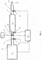
Fig. 1 is a schematic of an exhaust system configured to carry out the method according to the invention; - The drawings are provided by way of reference only, and will be acknowledged as not necessarily to scale.
- With reference to
Fig. 1 , an exhaust system 10 is shown. The exhaust system 10 in this particular example is for an agriculture vehicle specifically a tractor (not shown). The arrow X indicates the direction of flow of gases through the exhaust system 10. The arrow X indicates a direction from upstream to downstream. It will be understood that throughout the following description the terms urea and NH3 such as anhydrous ammonia can be used interchangeably. - The exhaust system 10 comprises an
internal combustion engine 12, acatalyst 14, aurea tank 16, aurea injector 18, anupstream NOx sensor 20, adownstream temperature sensor 22, atemperature sensor 24 and anengine control unit 26. - The
internal combustion engine 12 in this example is specifically a diesel engine. Theinternal combustion engine 12 is configured to drive a transmission (not shown) of the tractor. Theinternal combustion engine 12 burns diesel fuel with atmospheric air and produces power and waste gases, the waste gases commonly being known as exhaust gases. The exhaust gases are rich in particulates and nitrous oxides. - The
internal combustion engine 12 is in fluid communication with thecatalyst 14 viaconduit 28. The exhaust gases from theinternal combustion engine 12 exit theinternal combustion engine 12 at A pass viaconduit 28 and enter thecatalyst 14 at B. Theconduit 28 between theinternal combustion engine 12 and thecatalyst 14 being formed by any suitable means for example a tube or conventional exhaust pipe constructed from for example mild steel or stainless steel and may be ceramic coated to provide better thermodynamic properties of the fluid connection. - The
catalyst 14 is a selective catalytic reduction catalyst but may be of another catalyst type for example a diesel oxidation catalyst, an ammonia oxidation catalyst or a hybrid of different catalyst types. - Exhaust gases exit the
catalyst 14 at C and enter afurther conduit 30 known as a tail pipe or stack. The exhaust gases exit theconduit 30 at D. D being open to the atmosphere. Theconduit 30 may be of any conventional design. - The
urea tank 16 is provided as a reservoir for urea NH3. The urea is used as a dosing agent for the exhaust system 10. The ureatank 16 is in fluid communication with theurea injector 18 vialine 32. - The
urea injector 18 is of suitable type and is provided to dose the exhaust gases in the exhaust system 10 with urea from theurea tank 16. In this example theurea injector 18 is provided inconduit 28 between A and B such that urea may be administered to the exhausts prior to them entering thecatalyst 14. - The upstream NOx sensor (UNS) 20 is provided in the
conduit 28 upstream of theurea injector 18 and is configured to provide readings/measurements of the NOx levels in the exhaust gases leaving theinternal combustion engine 12. - The downstream NOx sensor (DNS) 22 is provided in the
conduit 30 between C and D. The downstream NOx sensor is thus situated downstream of thecatalyst 14, theurea injector 18 and theupstream NOx sensor 20. Thedownstream NOx sensor 22 is configured to measure the levels of NOx in exhaust gases in theconduit 30, i.e. downstream of thecatalyst 14. - The temperature sensor (TS) 24 in this example is situated in the
conduit 28 between A and B. In other examples thetemperature sensor 24 may be omitted. Thetemperature sensor 24 is also situated between theurea injector 18 and thecatalyst 14. Thetemperature sensor 24 is of any suitable type. Thetemperature sensor 24 is configured to measure the temperature of exhaust gases flowing in theconduit 28. That is, the temperature sensor is used to measure the temperature of exhaust gases as they exit theinternal combustion engine 12 and before they enter thecatalyst 14. In alternative embodiments it will be understood that thetemperature sensor 24 may be upstream of theurea sensor 18 and/or further temperature sensors may be positioned throughout the exhaust system 10. - The engine control unit (ECU) 26 is provided as part of the exhaust system 10. However, it will be understood that the
engine control unit 26 may be a main or auxiliary control unit provided as a standalone control unit on a vehicle or in data communication with a main/further control unit on the vehicle. - In this specific example, the
engine control unit 26 is a main engine control unit for the vehicle and is configured to receive measurements/reading from vehicle sensors and send messages to various vehicle components and devices. - The
engine control unit 26 is in data communication with each of theinternal combustion engine 12, theurea injector 18, theupstream NOx sensor 20, thedownstream NOx sensor 22 and thetemperature sensor 24. - When the exhaust system 10 is in use exhaust gases containing NOx are expelled from the
internal combustion engine 12 and are vented to the atmosphere at D. - To reduce the NOx content in the exhaust gases, the exhaust gases are dosed with urea (NH3) at the
urea injector 18 before entering thecatalyst 14. This process is well known and is called Selective Catalytic Reduction. - During the SCR process, not all the urea which is dosed to the exhaust gases to react with the NOx is consumed.
- As such, it is useful to know the ratio of NOx to NH3 in the exhaust gases at D.
- It would be possible to introduce a further sensor into the system in the
conduit 30 between C and D and to use this sensor to measure NH3 content in the exhaust gases at this stage, combined with the data measured from thedownstream NOx sensor 22 it would then be possible to calculate the relative ratios of NOx and NH3 in the exhaust gases. - Disadvantageously, the addition of a further sensor to measure the levels of NH3 in the exhaust gases increases the system cost and complexity. As such it is preferential to utilise the sensors provided in the exhaust system 10 to calculate the relative ratios of NOx and NH3 in the exhaust gases.
- Thus to calculate the relative ratios of NOx and NH3 in the exhaust gases, when the exhaust system 10 is in use, firstly a datum reading of NOx level is measured by the upstream NOx sensor 20 (first NOx level) and communicated to the
ECU 26. The exhaust gases are next dosed with a known quantity i.e. first predetermined dose of NH3 at theurea injector 18 which is downstream of thedownstream NOx sensor 20. The exhaust gases, now enriched with NH3 pass into thecatalyst 14. In thecatalyst 14, in general terms, a chemical reduction reaction takes place whereby the NH3 reacts with the NOx to convert some of the NOx to H2o and O2. However, not all the NOx and NH3 react to create H20 and O2 and as such the exhaust gases exiting thecatalyst 14 at C contain amongst other gases and particles, H2O, O2, NH3 and NOx. The remaining level of NOx (second NOx level) is then measured by thedownstream NOx sensor 22. - The preceding process occurs continually when the exhaust system is in use in a conventional manner when NOx reduction is required. The reaction generally produces stable results and conversion ratios.
- To calculate the relative ratios of NH3 the NOx and thereby check that the process is running correctly, the dose of NH3 applied to the exhaust gases at the
urea injector 18 is spiked to a second predetermined dose. That is, the dosing of urea is normally stable and relative to the measured NOx levels and is applied at a first predetermined level which is appropriate to the measured NOx levels at theupstream NOx sensor 20 and is set according to a predetermined dosing map. The second predetermined dose or spiked level is significantly higher than what would be required according to the aforementioned dosing map. The NOx levels are then measured in the exhaust gases in theconduit 30 by the downstream NOx sensor 22 (third NOx level). - The difference between the second and third NOx levels can then be computed by the
engine control unit 26 and compared to a stored map to lookup the relative ratio of NH3 and NOx. The stored map being constructed from results acquired from testing. - The
temperature sensor 24 can be used to provide further data and more precisely estimate the reading since the temperature of the exhaust gases entering thecatalyst 14 would be known. - In alternative embodiments a further catalyst may be provided in the exhaust system 10. In a specific embodiment this further catalyst is a DOC catalyst and is positioned upstream of the
upstream NOx sensor 20. - Furthermore the exhaust system 10 may include a diesel particulate filter. This diesel particulate filter may for instance be situated downstream of the
catalyst 14. - The invention is not limited to the embodiments or examples described herein, and may be modified or adapted without departing from the scope of the present invention.
Claims (8)
- A method of determining relative ratio of NOx to NH3 in exhaust gases, the method comprising the steps of:a) Providing an exhaust system for an agricultural vehicle, the exhaust system comprising:an upstream NOx Sensor;a downstream NOx sensor;a first catalyst;an urea injector; andan exhaust control unit;b) Measuring a first NOx level at the upstream NOx sensor;c) Administering a first predetermined dose of NH3 to the exhaust system;d) Measuring a second NOx level at the downstream NOx sensor;e) Administering a second predetermined dose of NH3 to the exhaust system;f) Measuring a third NOx level at the downstream NOx sensor;g) Calculating the difference between the second NOx level and the third NOx level;h) Comparing the difference to a lookup table to determine the relative ratio of NH3 and NOx.
- The method according to claim 1 wherein the second predetermined dose of NH3 is a larger than the first predetermined dose of NH3.
- The method according to claim 1 or 2 wherein the exhaust system further comprises a second catalyst.
- The method according to any preceding claim wherein the first catalyst is a selective catalytic reduction catalyst.
- The method according to claims 3 to 4 wherein the first catalyst is an ammonia oxidation catalyst.
- The method according to any preceding claim wherein the exhaust system further comprises a temperature sensor.
- The method according to any preceding claim wherein the exhaust system further comprises a diesel particulate filter.
- An agricultural vehicle including an exhaust system configured to carry out the method of according to any preceding claim.
Applications Claiming Priority (1)
| Application Number | Priority Date | Filing Date | Title |
|---|---|---|---|
| GBGB1818633.8A GB201818633D0 (en) | 2018-11-15 | 2018-11-15 | Nox slip detection |
Publications (2)
| Publication Number | Publication Date |
|---|---|
| EP3653853A1 true EP3653853A1 (en) | 2020-05-20 |
| EP3653853B1 EP3653853B1 (en) | 2021-03-24 |
Family
ID=64739915
Family Applications (1)
| Application Number | Title | Priority Date | Filing Date |
|---|---|---|---|
| EP19205303.1A Active EP3653853B1 (en) | 2018-11-15 | 2019-10-25 | Nox slip detection |
Country Status (2)
| Country | Link |
|---|---|
| EP (1) | EP3653853B1 (en) |
| GB (1) | GB201818633D0 (en) |
Cited By (1)
| Publication number | Priority date | Publication date | Assignee | Title |
|---|---|---|---|---|
| EP4056820A1 (en) * | 2021-03-11 | 2022-09-14 | Renault s.a.s | Method and system for detecting leaks of ammonia in a catalyst for selective reduction of nitrogen oxides |
Citations (6)
| Publication number | Priority date | Publication date | Assignee | Title |
|---|---|---|---|---|
| EP2226482A1 (en) * | 2009-03-06 | 2010-09-08 | MAN Nutzfahrzeuge AG | Method for adjusting the dosage amount of a reducing agent for selective catalytic reduction |
| US20110005203A1 (en) * | 2009-07-09 | 2011-01-13 | Gm Global Technology Operations, Inc. | Identifying ammonia non-slip conditions in a selective catlytic reduction application |
| US20110138779A1 (en) * | 2009-12-12 | 2011-06-16 | Bayerische Motoren Werke Aktiengesellschaft | Determination of the Linear Correlation Between Signals, Which are Determined by Means of NOx Sensors, in an SCR Exhaust Gas Aftertreatment System |
| WO2011075015A1 (en) * | 2009-12-18 | 2011-06-23 | Volvo Lastvagnar Ab | Method for controlling the reductant buffer level in an exhaust gas aftertreatment device |
| EP2439386A1 (en) * | 2010-10-06 | 2012-04-11 | Nicholas Michael Zayan | SCR ammonia slip detection |
| WO2015095332A1 (en) * | 2013-12-18 | 2015-06-25 | Cummins Inc. | Techniques for control of an scr aftertreatment system in response to nh3 slip conditions |
-
2018
- 2018-11-15 GB GBGB1818633.8A patent/GB201818633D0/en not_active Ceased
-
2019
- 2019-10-25 EP EP19205303.1A patent/EP3653853B1/en active Active
Patent Citations (6)
| Publication number | Priority date | Publication date | Assignee | Title |
|---|---|---|---|---|
| EP2226482A1 (en) * | 2009-03-06 | 2010-09-08 | MAN Nutzfahrzeuge AG | Method for adjusting the dosage amount of a reducing agent for selective catalytic reduction |
| US20110005203A1 (en) * | 2009-07-09 | 2011-01-13 | Gm Global Technology Operations, Inc. | Identifying ammonia non-slip conditions in a selective catlytic reduction application |
| US20110138779A1 (en) * | 2009-12-12 | 2011-06-16 | Bayerische Motoren Werke Aktiengesellschaft | Determination of the Linear Correlation Between Signals, Which are Determined by Means of NOx Sensors, in an SCR Exhaust Gas Aftertreatment System |
| WO2011075015A1 (en) * | 2009-12-18 | 2011-06-23 | Volvo Lastvagnar Ab | Method for controlling the reductant buffer level in an exhaust gas aftertreatment device |
| EP2439386A1 (en) * | 2010-10-06 | 2012-04-11 | Nicholas Michael Zayan | SCR ammonia slip detection |
| WO2015095332A1 (en) * | 2013-12-18 | 2015-06-25 | Cummins Inc. | Techniques for control of an scr aftertreatment system in response to nh3 slip conditions |
Cited By (2)
| Publication number | Priority date | Publication date | Assignee | Title |
|---|---|---|---|---|
| EP4056820A1 (en) * | 2021-03-11 | 2022-09-14 | Renault s.a.s | Method and system for detecting leaks of ammonia in a catalyst for selective reduction of nitrogen oxides |
| FR3120653A1 (en) * | 2021-03-11 | 2022-09-16 | Renault S.A.S | Method and system for detecting ammonia leaks in a catalyst for the selective reduction of nitrogen oxides |
Also Published As
| Publication number | Publication date |
|---|---|
| EP3653853B1 (en) | 2021-03-24 |
| GB201818633D0 (en) | 2019-01-02 |
Similar Documents
| Publication | Publication Date | Title |
|---|---|---|
| US9657630B2 (en) | Diagnostic systems and methods for selective catalytic reduction (SCR) systems based on NOx sensor feedback | |
| EP2376750B1 (en) | Scr closed loop control system | |
| CN101285414B (en) | Reductant injection control strategy | |
| US7736595B2 (en) | Dosing agent injection control for selective catalytic reduction catalysts | |
| US8061126B2 (en) | Nitrogen oxide estimation downstream of a selective catalytic reduction catalyst | |
| US9347356B2 (en) | Exhaust gas processing system independent to engine controls | |
| RU2623003C2 (en) | Detection method of sulphur poisoning within exhaustion cleaning system | |
| CN101660456B (en) | Lean nitrogen oxide emission control system and method | |
| US20090049899A1 (en) | Diagnostic method for an exhaust aftertreatment system | |
| US20170350291A1 (en) | SCR Conversion Efficiency Diagnostics | |
| US20150315951A1 (en) | Method for diagnosing an exhaust gas catalytic converter, diagnosis device and motor vehicle having such a device | |
| US9181845B2 (en) | Method for calculating the NO2 content at the inlet of a selective reduction catalyst and device for the implementation of this method | |
| US8024921B2 (en) | Method for operating an internal combustion engine and device for carrying out the method | |
| CN105308282A (en) | System and method for diagnosing the selective catalytic reduction system of a motor vehicle | |
| CN108915827A (en) | Improve the method for engine NOx emission amount based on SCR chemical reaction mathematical model | |
| US8549836B2 (en) | Method for operating an exhaust system, exhaust system and vehicle having an exhaust system | |
| US8682595B2 (en) | Method to estimate NO2 concentration in an exhaust gas of an internal combustion engine | |
| CN120265865A (en) | System including a hydrogen internal combustion engine and an aftertreatment system | |
| CN106150626A (en) | A kind of mechanical pump electromotor SCR device, control method and control device | |
| CN111911271A (en) | Method for zero calibration of a NOx sensor | |
| CN108625950A (en) | For monitoring and/or the method for the performance of control selections catalytic reduction device | |
| EP3653853B1 (en) | Nox slip detection | |
| US20200157994A1 (en) | Exhaust gas detection and treatment, and related systems | |
| CN113692481A (en) | Exhaust gas aftertreatment system | |
| EP4610474A1 (en) | Exhaust gas aftertreatment system for an ammonia fueled internal combustion engine |
Legal Events
| Date | Code | Title | Description |
|---|---|---|---|
| PUAI | Public reference made under article 153(3) epc to a published international application that has entered the european phase |
Free format text: ORIGINAL CODE: 0009012 |
|
| STAA | Information on the status of an ep patent application or granted ep patent |
Free format text: STATUS: THE APPLICATION HAS BEEN PUBLISHED |
|
| AK | Designated contracting states |
Kind code of ref document: A1 Designated state(s): AL AT BE BG CH CY CZ DE DK EE ES FI FR GB GR HR HU IE IS IT LI LT LU LV MC MK MT NL NO PL PT RO RS SE SI SK SM TR |
|
| AX | Request for extension of the european patent |
Extension state: BA ME |
|
| RIN1 | Information on inventor provided before grant (corrected) |
Inventor name: PESOLA, MIKKO Inventor name: HEIKKILA, JUHA Inventor name: WIHERSAARI, HUGO |
|
| STAA | Information on the status of an ep patent application or granted ep patent |
Free format text: STATUS: REQUEST FOR EXAMINATION WAS MADE |
|
| 17P | Request for examination filed |
Effective date: 20201120 |
|
| RBV | Designated contracting states (corrected) |
Designated state(s): AL AT BE BG CH CY CZ DE DK EE ES FI FR GB GR HR HU IE IS IT LI LT LU LV MC MK MT NL NO PL PT RO RS SE SI SK SM TR |
|
| RIC1 | Information provided on ipc code assigned before grant |
Ipc: F01N 3/20 20060101AFI20201202BHEP Ipc: F01N 11/00 20060101ALI20201202BHEP |
|
| GRAP | Despatch of communication of intention to grant a patent |
Free format text: ORIGINAL CODE: EPIDOSNIGR1 |
|
| STAA | Information on the status of an ep patent application or granted ep patent |
Free format text: STATUS: GRANT OF PATENT IS INTENDED |
|
| INTG | Intention to grant announced |
Effective date: 20210112 |
|
| GRAS | Grant fee paid |
Free format text: ORIGINAL CODE: EPIDOSNIGR3 |
|
| GRAA | (expected) grant |
Free format text: ORIGINAL CODE: 0009210 |
|
| STAA | Information on the status of an ep patent application or granted ep patent |
Free format text: STATUS: THE PATENT HAS BEEN GRANTED |
|
| AK | Designated contracting states |
Kind code of ref document: B1 Designated state(s): AL AT BE BG CH CY CZ DE DK EE ES FI FR GB GR HR HU IE IS IT LI LT LU LV MC MK MT NL NO PL PT RO RS SE SI SK SM TR |
|
| REG | Reference to a national code |
Ref country code: GB Ref legal event code: FG4D |
|
| REG | Reference to a national code |
Ref country code: CH Ref legal event code: EP |
|
| REG | Reference to a national code |
Ref country code: IE Ref legal event code: FG4D |
|
| REG | Reference to a national code |
Ref country code: DE Ref legal event code: R096 Ref document number: 602019003425 Country of ref document: DE Ref country code: AT Ref legal event code: REF Ref document number: 1374709 Country of ref document: AT Kind code of ref document: T Effective date: 20210415 |
|
| REG | Reference to a national code |
Ref country code: LT Ref legal event code: MG9D |
|
| PG25 | Lapsed in a contracting state [announced via postgrant information from national office to epo] |
Ref country code: NO Free format text: LAPSE BECAUSE OF FAILURE TO SUBMIT A TRANSLATION OF THE DESCRIPTION OR TO PAY THE FEE WITHIN THE PRESCRIBED TIME-LIMIT Effective date: 20210624 Ref country code: BG Free format text: LAPSE BECAUSE OF FAILURE TO SUBMIT A TRANSLATION OF THE DESCRIPTION OR TO PAY THE FEE WITHIN THE PRESCRIBED TIME-LIMIT Effective date: 20210624 Ref country code: HR Free format text: LAPSE BECAUSE OF FAILURE TO SUBMIT A TRANSLATION OF THE DESCRIPTION OR TO PAY THE FEE WITHIN THE PRESCRIBED TIME-LIMIT Effective date: 20210324 Ref country code: FI Free format text: LAPSE BECAUSE OF FAILURE TO SUBMIT A TRANSLATION OF THE DESCRIPTION OR TO PAY THE FEE WITHIN THE PRESCRIBED TIME-LIMIT Effective date: 20210324 Ref country code: GR Free format text: LAPSE BECAUSE OF FAILURE TO SUBMIT A TRANSLATION OF THE DESCRIPTION OR TO PAY THE FEE WITHIN THE PRESCRIBED TIME-LIMIT Effective date: 20210625 |
|
| PG25 | Lapsed in a contracting state [announced via postgrant information from national office to epo] |
Ref country code: LV Free format text: LAPSE BECAUSE OF FAILURE TO SUBMIT A TRANSLATION OF THE DESCRIPTION OR TO PAY THE FEE WITHIN THE PRESCRIBED TIME-LIMIT Effective date: 20210324 Ref country code: RS Free format text: LAPSE BECAUSE OF FAILURE TO SUBMIT A TRANSLATION OF THE DESCRIPTION OR TO PAY THE FEE WITHIN THE PRESCRIBED TIME-LIMIT Effective date: 20210324 Ref country code: SE Free format text: LAPSE BECAUSE OF FAILURE TO SUBMIT A TRANSLATION OF THE DESCRIPTION OR TO PAY THE FEE WITHIN THE PRESCRIBED TIME-LIMIT Effective date: 20210324 |
|
| REG | Reference to a national code |
Ref country code: NL Ref legal event code: MP Effective date: 20210324 |
|
| REG | Reference to a national code |
Ref country code: AT Ref legal event code: MK05 Ref document number: 1374709 Country of ref document: AT Kind code of ref document: T Effective date: 20210324 |
|
| PG25 | Lapsed in a contracting state [announced via postgrant information from national office to epo] |
Ref country code: NL Free format text: LAPSE BECAUSE OF FAILURE TO SUBMIT A TRANSLATION OF THE DESCRIPTION OR TO PAY THE FEE WITHIN THE PRESCRIBED TIME-LIMIT Effective date: 20210324 |
|
| PG25 | Lapsed in a contracting state [announced via postgrant information from national office to epo] |
Ref country code: EE Free format text: LAPSE BECAUSE OF FAILURE TO SUBMIT A TRANSLATION OF THE DESCRIPTION OR TO PAY THE FEE WITHIN THE PRESCRIBED TIME-LIMIT Effective date: 20210324 Ref country code: CZ Free format text: LAPSE BECAUSE OF FAILURE TO SUBMIT A TRANSLATION OF THE DESCRIPTION OR TO PAY THE FEE WITHIN THE PRESCRIBED TIME-LIMIT Effective date: 20210324 Ref country code: LT Free format text: LAPSE BECAUSE OF FAILURE TO SUBMIT A TRANSLATION OF THE DESCRIPTION OR TO PAY THE FEE WITHIN THE PRESCRIBED TIME-LIMIT Effective date: 20210324 Ref country code: SM Free format text: LAPSE BECAUSE OF FAILURE TO SUBMIT A TRANSLATION OF THE DESCRIPTION OR TO PAY THE FEE WITHIN THE PRESCRIBED TIME-LIMIT Effective date: 20210324 Ref country code: AT Free format text: LAPSE BECAUSE OF FAILURE TO SUBMIT A TRANSLATION OF THE DESCRIPTION OR TO PAY THE FEE WITHIN THE PRESCRIBED TIME-LIMIT Effective date: 20210324 |
|
| PG25 | Lapsed in a contracting state [announced via postgrant information from national office to epo] |
Ref country code: IS Free format text: LAPSE BECAUSE OF FAILURE TO SUBMIT A TRANSLATION OF THE DESCRIPTION OR TO PAY THE FEE WITHIN THE PRESCRIBED TIME-LIMIT Effective date: 20210724 Ref country code: PL Free format text: LAPSE BECAUSE OF FAILURE TO SUBMIT A TRANSLATION OF THE DESCRIPTION OR TO PAY THE FEE WITHIN THE PRESCRIBED TIME-LIMIT Effective date: 20210324 Ref country code: PT Free format text: LAPSE BECAUSE OF FAILURE TO SUBMIT A TRANSLATION OF THE DESCRIPTION OR TO PAY THE FEE WITHIN THE PRESCRIBED TIME-LIMIT Effective date: 20210726 Ref country code: RO Free format text: LAPSE BECAUSE OF FAILURE TO SUBMIT A TRANSLATION OF THE DESCRIPTION OR TO PAY THE FEE WITHIN THE PRESCRIBED TIME-LIMIT Effective date: 20210324 Ref country code: SK Free format text: LAPSE BECAUSE OF FAILURE TO SUBMIT A TRANSLATION OF THE DESCRIPTION OR TO PAY THE FEE WITHIN THE PRESCRIBED TIME-LIMIT Effective date: 20210324 |
|
| REG | Reference to a national code |
Ref country code: DE Ref legal event code: R097 Ref document number: 602019003425 Country of ref document: DE |
|
| PG25 | Lapsed in a contracting state [announced via postgrant information from national office to epo] |
Ref country code: ES Free format text: LAPSE BECAUSE OF FAILURE TO SUBMIT A TRANSLATION OF THE DESCRIPTION OR TO PAY THE FEE WITHIN THE PRESCRIBED TIME-LIMIT Effective date: 20210324 Ref country code: DK Free format text: LAPSE BECAUSE OF FAILURE TO SUBMIT A TRANSLATION OF THE DESCRIPTION OR TO PAY THE FEE WITHIN THE PRESCRIBED TIME-LIMIT Effective date: 20210324 Ref country code: AL Free format text: LAPSE BECAUSE OF FAILURE TO SUBMIT A TRANSLATION OF THE DESCRIPTION OR TO PAY THE FEE WITHIN THE PRESCRIBED TIME-LIMIT Effective date: 20210324 |
|
| PLBE | No opposition filed within time limit |
Free format text: ORIGINAL CODE: 0009261 |
|
| STAA | Information on the status of an ep patent application or granted ep patent |
Free format text: STATUS: NO OPPOSITION FILED WITHIN TIME LIMIT |
|
| 26N | No opposition filed |
Effective date: 20220104 |
|
| PG25 | Lapsed in a contracting state [announced via postgrant information from national office to epo] |
Ref country code: IS Free format text: LAPSE BECAUSE OF FAILURE TO SUBMIT A TRANSLATION OF THE DESCRIPTION OR TO PAY THE FEE WITHIN THE PRESCRIBED TIME-LIMIT Effective date: 20210724 |
|
| REG | Reference to a national code |
Ref country code: BE Ref legal event code: MM Effective date: 20211031 |
|
| PG25 | Lapsed in a contracting state [announced via postgrant information from national office to epo] |
Ref country code: MC Free format text: LAPSE BECAUSE OF FAILURE TO SUBMIT A TRANSLATION OF THE DESCRIPTION OR TO PAY THE FEE WITHIN THE PRESCRIBED TIME-LIMIT Effective date: 20210324 |
|
| PG25 | Lapsed in a contracting state [announced via postgrant information from national office to epo] |
Ref country code: LU Free format text: LAPSE BECAUSE OF NON-PAYMENT OF DUE FEES Effective date: 20211025 Ref country code: BE Free format text: LAPSE BECAUSE OF NON-PAYMENT OF DUE FEES Effective date: 20211031 |
|
| PG25 | Lapsed in a contracting state [announced via postgrant information from national office to epo] |
Ref country code: IE Free format text: LAPSE BECAUSE OF NON-PAYMENT OF DUE FEES Effective date: 20211025 |
|
| REG | Reference to a national code |
Ref country code: CH Ref legal event code: PL |
|
| P01 | Opt-out of the competence of the unified patent court (upc) registered |
Effective date: 20230518 |
|
| PG25 | Lapsed in a contracting state [announced via postgrant information from national office to epo] |
Ref country code: CY Free format text: LAPSE BECAUSE OF FAILURE TO SUBMIT A TRANSLATION OF THE DESCRIPTION OR TO PAY THE FEE WITHIN THE PRESCRIBED TIME-LIMIT Effective date: 20210324 |
|
| PG25 | Lapsed in a contracting state [announced via postgrant information from national office to epo] |
Ref country code: LI Free format text: LAPSE BECAUSE OF NON-PAYMENT OF DUE FEES Effective date: 20221031 Ref country code: HU Free format text: LAPSE BECAUSE OF FAILURE TO SUBMIT A TRANSLATION OF THE DESCRIPTION OR TO PAY THE FEE WITHIN THE PRESCRIBED TIME-LIMIT; INVALID AB INITIO Effective date: 20191025 Ref country code: CH Free format text: LAPSE BECAUSE OF NON-PAYMENT OF DUE FEES Effective date: 20221031 |
|
| PG25 | Lapsed in a contracting state [announced via postgrant information from national office to epo] |
Ref country code: SI Free format text: LAPSE BECAUSE OF FAILURE TO SUBMIT A TRANSLATION OF THE DESCRIPTION OR TO PAY THE FEE WITHIN THE PRESCRIBED TIME-LIMIT Effective date: 20210324 |
|
| PG25 | Lapsed in a contracting state [announced via postgrant information from national office to epo] |
Ref country code: MK Free format text: LAPSE BECAUSE OF FAILURE TO SUBMIT A TRANSLATION OF THE DESCRIPTION OR TO PAY THE FEE WITHIN THE PRESCRIBED TIME-LIMIT Effective date: 20210324 |
|
| PG25 | Lapsed in a contracting state [announced via postgrant information from national office to epo] |
Ref country code: MT Free format text: LAPSE BECAUSE OF FAILURE TO SUBMIT A TRANSLATION OF THE DESCRIPTION OR TO PAY THE FEE WITHIN THE PRESCRIBED TIME-LIMIT Effective date: 20210324 |
|
| REG | Reference to a national code |
Ref country code: GB Ref legal event code: 732E Free format text: REGISTERED BETWEEN 20241205 AND 20241211 |
|
| REG | Reference to a national code |
Ref country code: DE Ref legal event code: R081 Ref document number: 602019003425 Country of ref document: DE Owner name: AGCO POWER OY, FI Free format text: FORMER OWNER: AGCO INTERNATIONAL GMBH, NEUHAUSEN AM RHEINFALL, CH |
|
| PG25 | Lapsed in a contracting state [announced via postgrant information from national office to epo] |
Ref country code: TR Free format text: LAPSE BECAUSE OF FAILURE TO SUBMIT A TRANSLATION OF THE DESCRIPTION OR TO PAY THE FEE WITHIN THE PRESCRIBED TIME-LIMIT Effective date: 20210324 |
|
| PGFP | Annual fee paid to national office [announced via postgrant information from national office to epo] |
Ref country code: DE Payment date: 20251021 Year of fee payment: 7 |
|
| PGFP | Annual fee paid to national office [announced via postgrant information from national office to epo] |
Ref country code: GB Payment date: 20251022 Year of fee payment: 7 |
|
| PGFP | Annual fee paid to national office [announced via postgrant information from national office to epo] |
Ref country code: IT Payment date: 20251021 Year of fee payment: 7 |
|
| PGFP | Annual fee paid to national office [announced via postgrant information from national office to epo] |
Ref country code: FR Payment date: 20251030 Year of fee payment: 7 |