EP3653576A2 - Anode material of nano-silicon having multilayer-graphene as carrier and coated with silicon suboxide and with amorphous carbon layer and method for fabricating the same - Google Patents
Anode material of nano-silicon having multilayer-graphene as carrier and coated with silicon suboxide and with amorphous carbon layer and method for fabricating the same Download PDFInfo
- Publication number
- EP3653576A2 EP3653576A2 EP19185627.7A EP19185627A EP3653576A2 EP 3653576 A2 EP3653576 A2 EP 3653576A2 EP 19185627 A EP19185627 A EP 19185627A EP 3653576 A2 EP3653576 A2 EP 3653576A2
- Authority
- EP
- European Patent Office
- Prior art keywords
- silicon
- graphene
- multilayer
- anode material
- carrier
- Prior art date
- Legal status (The legal status is an assumption and is not a legal conclusion. Google has not performed a legal analysis and makes no representation as to the accuracy of the status listed.)
- Withdrawn
Links
- 229910052710 silicon Inorganic materials 0.000 title claims abstract description 85
- XUIMIQQOPSSXEZ-UHFFFAOYSA-N Silicon Chemical compound [Si] XUIMIQQOPSSXEZ-UHFFFAOYSA-N 0.000 title claims abstract description 71
- 239000010405 anode material Substances 0.000 title claims abstract description 64
- 239000010703 silicon Substances 0.000 title claims abstract description 64
- 229910021389 graphene Inorganic materials 0.000 title claims abstract description 62
- 239000005543 nano-size silicon particle Substances 0.000 title claims abstract description 51
- 229910003481 amorphous carbon Inorganic materials 0.000 title claims abstract description 44
- 238000000034 method Methods 0.000 title claims description 46
- 230000003139 buffering effect Effects 0.000 claims abstract description 13
- HEMHJVSKTPXQMS-UHFFFAOYSA-M Sodium hydroxide Chemical compound [OH-].[Na+] HEMHJVSKTPXQMS-UHFFFAOYSA-M 0.000 claims description 33
- OKTJSMMVPCPJKN-UHFFFAOYSA-N Carbon Chemical compound [C] OKTJSMMVPCPJKN-UHFFFAOYSA-N 0.000 claims description 31
- 229910052799 carbon Inorganic materials 0.000 claims description 28
- 239000000203 mixture Substances 0.000 claims description 20
- KRKNYBCHXYNGOX-UHFFFAOYSA-N citric acid Chemical compound OC(=O)CC(O)(C(O)=O)CC(O)=O KRKNYBCHXYNGOX-UHFFFAOYSA-N 0.000 claims description 18
- 238000002156 mixing Methods 0.000 claims description 17
- 239000011258 core-shell material Substances 0.000 claims description 12
- 239000006258 conductive agent Substances 0.000 claims description 10
- 239000002904 solvent Substances 0.000 claims description 9
- 238000001354 calcination Methods 0.000 claims description 8
- 238000010298 pulverizing process Methods 0.000 claims description 7
- 238000007873 sieving Methods 0.000 claims description 5
- 239000011863 silicon-based powder Substances 0.000 claims description 5
- 239000002245 particle Substances 0.000 claims description 4
- 239000007858 starting material Substances 0.000 claims description 4
- 239000011230 binding agent Substances 0.000 claims description 3
- 230000007935 neutral effect Effects 0.000 claims description 3
- 239000000843 powder Substances 0.000 claims description 3
- 238000000197 pyrolysis Methods 0.000 claims description 3
- 239000008367 deionised water Substances 0.000 claims description 2
- 229910021641 deionized water Inorganic materials 0.000 claims description 2
- XLYOFNOQVPJJNP-UHFFFAOYSA-N water Chemical compound O XLYOFNOQVPJJNP-UHFFFAOYSA-N 0.000 claims description 2
- VEXZGXHMUGYJMC-UHFFFAOYSA-N Hydrochloric acid Chemical compound Cl VEXZGXHMUGYJMC-UHFFFAOYSA-N 0.000 claims 4
- QTBSBXVTEAMEQO-UHFFFAOYSA-N Acetic acid Chemical compound CC(O)=O QTBSBXVTEAMEQO-UHFFFAOYSA-N 0.000 claims 3
- LFQSCWFLJHTTHZ-UHFFFAOYSA-N Ethanol Chemical compound CCO LFQSCWFLJHTTHZ-UHFFFAOYSA-N 0.000 claims 3
- PEDCQBHIVMGVHV-UHFFFAOYSA-N Glycerine Chemical compound OCC(O)CO PEDCQBHIVMGVHV-UHFFFAOYSA-N 0.000 claims 3
- QAOWNCQODCNURD-UHFFFAOYSA-N Sulfuric acid Chemical compound OS(O)(=O)=O QAOWNCQODCNURD-UHFFFAOYSA-N 0.000 claims 3
- KXGFMDJXCMQABM-UHFFFAOYSA-N 2-methoxy-6-methylphenol Chemical compound [CH]OC1=CC=CC([CH])=C1O KXGFMDJXCMQABM-UHFFFAOYSA-N 0.000 claims 2
- WQZGKKKJIJFFOK-GASJEMHNSA-N Glucose Natural products OC[C@H]1OC(O)[C@H](O)[C@@H](O)[C@@H]1O WQZGKKKJIJFFOK-GASJEMHNSA-N 0.000 claims 2
- GRYLNZFGIOXLOG-UHFFFAOYSA-N Nitric acid Chemical compound O[N+]([O-])=O GRYLNZFGIOXLOG-UHFFFAOYSA-N 0.000 claims 2
- 239000002202 Polyethylene glycol Substances 0.000 claims 2
- 239000004372 Polyvinyl alcohol Substances 0.000 claims 2
- CZMRCDWAGMRECN-UGDNZRGBSA-N Sucrose Chemical compound O[C@H]1[C@H](O)[C@@H](CO)O[C@@]1(CO)O[C@@H]1[C@H](O)[C@@H](O)[C@H](O)[C@@H](CO)O1 CZMRCDWAGMRECN-UGDNZRGBSA-N 0.000 claims 2
- 229930006000 Sucrose Natural products 0.000 claims 2
- 239000010426 asphalt Substances 0.000 claims 2
- WQZGKKKJIJFFOK-VFUOTHLCSA-N beta-D-glucose Chemical compound OC[C@H]1O[C@@H](O)[C@H](O)[C@@H](O)[C@@H]1O WQZGKKKJIJFFOK-VFUOTHLCSA-N 0.000 claims 2
- 239000003822 epoxy resin Substances 0.000 claims 2
- 239000008103 glucose Substances 0.000 claims 2
- 229910017604 nitric acid Inorganic materials 0.000 claims 2
- 229920001568 phenolic resin Polymers 0.000 claims 2
- 239000005011 phenolic resin Substances 0.000 claims 2
- 229920002239 polyacrylonitrile Polymers 0.000 claims 2
- 229920000767 polyaniline Polymers 0.000 claims 2
- 229920000647 polyepoxide Polymers 0.000 claims 2
- 229920001223 polyethylene glycol Polymers 0.000 claims 2
- 229920002451 polyvinyl alcohol Polymers 0.000 claims 2
- 229920000036 polyvinylpyrrolidone Polymers 0.000 claims 2
- 239000001267 polyvinylpyrrolidone Substances 0.000 claims 2
- 235000013855 polyvinylpyrrolidone Nutrition 0.000 claims 2
- 239000005720 sucrose Substances 0.000 claims 2
- 229930195735 unsaturated hydrocarbon Natural products 0.000 claims 2
- FHVDTGUDJYJELY-UHFFFAOYSA-N 6-{[2-carboxy-4,5-dihydroxy-6-(phosphanyloxy)oxan-3-yl]oxy}-4,5-dihydroxy-3-phosphanyloxane-2-carboxylic acid Chemical compound O1C(C(O)=O)C(P)C(O)C(O)C1OC1C(C(O)=O)OC(OP)C(O)C1O FHVDTGUDJYJELY-UHFFFAOYSA-N 0.000 claims 1
- 229920002134 Carboxymethyl cellulose Polymers 0.000 claims 1
- 229920001661 Chitosan Polymers 0.000 claims 1
- 239000002033 PVDF binder Substances 0.000 claims 1
- 229940072056 alginate Drugs 0.000 claims 1
- 229920000615 alginic acid Polymers 0.000 claims 1
- 235000010443 alginic acid Nutrition 0.000 claims 1
- 238000000498 ball milling Methods 0.000 claims 1
- 229920006184 cellulose methylcellulose Polymers 0.000 claims 1
- 239000011888 foil Substances 0.000 claims 1
- 238000000227 grinding Methods 0.000 claims 1
- 125000002887 hydroxy group Chemical group [H]O* 0.000 claims 1
- 238000003754 machining Methods 0.000 claims 1
- 239000002184 metal Substances 0.000 claims 1
- 229920002981 polyvinylidene fluoride Polymers 0.000 claims 1
- 229920003048 styrene butadiene rubber Polymers 0.000 claims 1
- 239000011248 coating agent Substances 0.000 abstract description 3
- 238000000576 coating method Methods 0.000 abstract description 3
- VYPSYNLAJGMNEJ-UHFFFAOYSA-N Silicium dioxide Chemical compound O=[Si]=O VYPSYNLAJGMNEJ-UHFFFAOYSA-N 0.000 description 129
- 229910052814 silicon oxide Inorganic materials 0.000 description 111
- 239000000463 material Substances 0.000 description 32
- 239000002931 mesocarbon microbead Substances 0.000 description 27
- 238000007599 discharging Methods 0.000 description 17
- 238000012360 testing method Methods 0.000 description 17
- 230000000052 comparative effect Effects 0.000 description 15
- 229910052760 oxygen Inorganic materials 0.000 description 14
- 239000002002 slurry Substances 0.000 description 13
- 229910052681 coesite Inorganic materials 0.000 description 9
- 229910052906 cristobalite Inorganic materials 0.000 description 9
- 239000000377 silicon dioxide Substances 0.000 description 9
- 229910052682 stishovite Inorganic materials 0.000 description 9
- 229910052905 tridymite Inorganic materials 0.000 description 9
- HBBGRARXTFLTSG-UHFFFAOYSA-N Lithium ion Chemical compound [Li+] HBBGRARXTFLTSG-UHFFFAOYSA-N 0.000 description 8
- 229910001416 lithium ion Inorganic materials 0.000 description 8
- 238000001878 scanning electron micrograph Methods 0.000 description 8
- 239000011149 active material Substances 0.000 description 7
- 239000003575 carbonaceous material Substances 0.000 description 7
- 229910002804 graphite Inorganic materials 0.000 description 7
- 239000010439 graphite Substances 0.000 description 7
- 239000002131 composite material Substances 0.000 description 6
- 229910052744 lithium Inorganic materials 0.000 description 6
- 238000013507 mapping Methods 0.000 description 6
- 230000002441 reversible effect Effects 0.000 description 6
- 238000002216 synchrotron radiation X-ray diffraction Methods 0.000 description 6
- WHXSMMKQMYFTQS-UHFFFAOYSA-N Lithium Chemical compound [Li] WHXSMMKQMYFTQS-UHFFFAOYSA-N 0.000 description 5
- 238000004458 analytical method Methods 0.000 description 5
- QVGXLLKOCUKJST-UHFFFAOYSA-N atomic oxygen Chemical compound [O] QVGXLLKOCUKJST-UHFFFAOYSA-N 0.000 description 5
- 239000007770 graphite material Substances 0.000 description 5
- 239000001301 oxygen Substances 0.000 description 5
- RYGMFSIKBFXOCR-UHFFFAOYSA-N Copper Chemical compound [Cu] RYGMFSIKBFXOCR-UHFFFAOYSA-N 0.000 description 4
- 239000011889 copper foil Substances 0.000 description 4
- 230000014759 maintenance of location Effects 0.000 description 4
- 238000002360 preparation method Methods 0.000 description 4
- 239000011257 shell material Substances 0.000 description 4
- 238000010183 spectrum analysis Methods 0.000 description 4
- FUJCRWPEOMXPAD-UHFFFAOYSA-N Li2O Inorganic materials [Li+].[Li+].[O-2] FUJCRWPEOMXPAD-UHFFFAOYSA-N 0.000 description 3
- 238000003763 carbonization Methods 0.000 description 3
- 238000006243 chemical reaction Methods 0.000 description 3
- 230000007423 decrease Effects 0.000 description 3
- 230000007547 defect Effects 0.000 description 3
- 238000010586 diagram Methods 0.000 description 3
- XUCJHNOBJLKZNU-UHFFFAOYSA-M dilithium;hydroxide Chemical compound [Li+].[Li+].[OH-] XUCJHNOBJLKZNU-UHFFFAOYSA-M 0.000 description 3
- 238000007606 doctor blade method Methods 0.000 description 3
- 238000003837 high-temperature calcination Methods 0.000 description 3
- 229910052909 inorganic silicate Inorganic materials 0.000 description 3
- 230000036961 partial effect Effects 0.000 description 3
- LIVNPJMFVYWSIS-UHFFFAOYSA-N silicon monoxide Inorganic materials [Si-]#[O+] LIVNPJMFVYWSIS-UHFFFAOYSA-N 0.000 description 3
- 238000001228 spectrum Methods 0.000 description 3
- FSSPGSAQUIYDCN-UHFFFAOYSA-N 1,3-Propane sultone Chemical compound O=S1(=O)CCCO1 FSSPGSAQUIYDCN-UHFFFAOYSA-N 0.000 description 2
- VAYTZRYEBVHVLE-UHFFFAOYSA-N 1,3-dioxol-2-one Chemical compound O=C1OC=CO1 VAYTZRYEBVHVLE-UHFFFAOYSA-N 0.000 description 2
- SBLRHMKNNHXPHG-UHFFFAOYSA-N 4-fluoro-1,3-dioxolan-2-one Chemical compound FC1COC(=O)O1 SBLRHMKNNHXPHG-UHFFFAOYSA-N 0.000 description 2
- KMTRUDSVKNLOMY-UHFFFAOYSA-N Ethylene carbonate Chemical compound O=C1OCCO1 KMTRUDSVKNLOMY-UHFFFAOYSA-N 0.000 description 2
- CDBYLPFSWZWCQE-UHFFFAOYSA-L Sodium Carbonate Chemical compound [Na+].[Na+].[O-]C([O-])=O CDBYLPFSWZWCQE-UHFFFAOYSA-L 0.000 description 2
- 125000004429 atom Chemical group 0.000 description 2
- 238000005229 chemical vapour deposition Methods 0.000 description 2
- 239000013065 commercial product Substances 0.000 description 2
- 238000005336 cracking Methods 0.000 description 2
- 238000011161 development Methods 0.000 description 2
- 230000018109 developmental process Effects 0.000 description 2
- IEJIGPNLZYLLBP-UHFFFAOYSA-N dimethyl carbonate Chemical compound COC(=O)OC IEJIGPNLZYLLBP-UHFFFAOYSA-N 0.000 description 2
- 239000006185 dispersion Substances 0.000 description 2
- 238000009826 distribution Methods 0.000 description 2
- 239000007789 gas Substances 0.000 description 2
- 230000002427 irreversible effect Effects 0.000 description 2
- 238000004519 manufacturing process Methods 0.000 description 2
- 238000012764 semi-quantitative analysis Methods 0.000 description 2
- 239000002210 silicon-based material Substances 0.000 description 2
- 229910001290 LiPF6 Inorganic materials 0.000 description 1
- -1 Na2CO3 Chemical class 0.000 description 1
- 229910018557 Si O Inorganic materials 0.000 description 1
- 229910008045 Si-Si Inorganic materials 0.000 description 1
- BLRPTPMANUNPDV-UHFFFAOYSA-N Silane Chemical compound [SiH4] BLRPTPMANUNPDV-UHFFFAOYSA-N 0.000 description 1
- 229910006411 Si—Si Inorganic materials 0.000 description 1
- OBNDGIHQAIXEAO-UHFFFAOYSA-N [O].[Si] Chemical compound [O].[Si] OBNDGIHQAIXEAO-UHFFFAOYSA-N 0.000 description 1
- 239000000654 additive Substances 0.000 description 1
- 239000003513 alkali Substances 0.000 description 1
- 239000006183 anode active material Substances 0.000 description 1
- 238000013459 approach Methods 0.000 description 1
- 229910021383 artificial graphite Inorganic materials 0.000 description 1
- 230000015572 biosynthetic process Effects 0.000 description 1
- 239000006227 byproduct Substances 0.000 description 1
- 238000004364 calculation method Methods 0.000 description 1
- 239000003990 capacitor Substances 0.000 description 1
- PYTMYKVIJXPNBD-UHFFFAOYSA-N clomiphene citrate Chemical compound [H+].[H+].[H+].[O-]C(=O)CC(O)(CC([O-])=O)C([O-])=O.C1=CC(OCCN(CC)CC)=CC=C1C(C=1C=CC=CC=1)=C(Cl)C1=CC=CC=C1 PYTMYKVIJXPNBD-UHFFFAOYSA-N 0.000 description 1
- 239000013078 crystal Substances 0.000 description 1
- 230000003247 decreasing effect Effects 0.000 description 1
- 230000001419 dependent effect Effects 0.000 description 1
- 230000000694 effects Effects 0.000 description 1
- 238000005516 engineering process Methods 0.000 description 1
- 238000005530 etching Methods 0.000 description 1
- UQOULBWSWCWZJC-UHFFFAOYSA-N ethene;methyl hydrogen carbonate Chemical compound C=C.COC(O)=O UQOULBWSWCWZJC-UHFFFAOYSA-N 0.000 description 1
- 239000011325 microbead Substances 0.000 description 1
- 229910021382 natural graphite Inorganic materials 0.000 description 1
- 230000003647 oxidation Effects 0.000 description 1
- 238000007254 oxidation reaction Methods 0.000 description 1
- 125000004430 oxygen atom Chemical group O* 0.000 description 1
- 238000001420 photoelectron spectroscopy Methods 0.000 description 1
- 239000000047 product Substances 0.000 description 1
- 239000002994 raw material Substances 0.000 description 1
- 230000002829 reductive effect Effects 0.000 description 1
- 239000011369 resultant mixture Substances 0.000 description 1
- 230000000630 rising effect Effects 0.000 description 1
- 150000003839 salts Chemical class 0.000 description 1
- 229910000029 sodium carbonate Inorganic materials 0.000 description 1
- 238000005211 surface analysis Methods 0.000 description 1
- 238000001308 synthesis method Methods 0.000 description 1
- 238000010947 wet-dispersion method Methods 0.000 description 1
Images





Classifications
-
- C—CHEMISTRY; METALLURGY
- C01—INORGANIC CHEMISTRY
- C01B—NON-METALLIC ELEMENTS; COMPOUNDS THEREOF; METALLOIDS OR COMPOUNDS THEREOF NOT COVERED BY SUBCLASS C01C
- C01B33/00—Silicon; Compounds thereof
- C01B33/113—Silicon oxides; Hydrates thereof
-
- C—CHEMISTRY; METALLURGY
- C01—INORGANIC CHEMISTRY
- C01B—NON-METALLIC ELEMENTS; COMPOUNDS THEREOF; METALLOIDS OR COMPOUNDS THEREOF NOT COVERED BY SUBCLASS C01C
- C01B32/00—Carbon; Compounds thereof
- C01B32/15—Nano-sized carbon materials
- C01B32/182—Graphene
- C01B32/194—After-treatment
-
- H—ELECTRICITY
- H01—ELECTRIC ELEMENTS
- H01M—PROCESSES OR MEANS, e.g. BATTERIES, FOR THE DIRECT CONVERSION OF CHEMICAL ENERGY INTO ELECTRICAL ENERGY
- H01M10/00—Secondary cells; Manufacture thereof
- H01M10/05—Accumulators with non-aqueous electrolyte
- H01M10/052—Li-accumulators
- H01M10/0525—Rocking-chair batteries, i.e. batteries with lithium insertion or intercalation in both electrodes; Lithium-ion batteries
-
- H—ELECTRICITY
- H01—ELECTRIC ELEMENTS
- H01M—PROCESSES OR MEANS, e.g. BATTERIES, FOR THE DIRECT CONVERSION OF CHEMICAL ENERGY INTO ELECTRICAL ENERGY
- H01M4/00—Electrodes
- H01M4/02—Electrodes composed of, or comprising, active material
- H01M4/13—Electrodes for accumulators with non-aqueous electrolyte, e.g. for lithium-accumulators; Processes of manufacture thereof
- H01M4/139—Processes of manufacture
- H01M4/1393—Processes of manufacture of electrodes based on carbonaceous material, e.g. graphite-intercalation compounds or CFx
-
- H—ELECTRICITY
- H01—ELECTRIC ELEMENTS
- H01M—PROCESSES OR MEANS, e.g. BATTERIES, FOR THE DIRECT CONVERSION OF CHEMICAL ENERGY INTO ELECTRICAL ENERGY
- H01M4/00—Electrodes
- H01M4/02—Electrodes composed of, or comprising, active material
- H01M4/13—Electrodes for accumulators with non-aqueous electrolyte, e.g. for lithium-accumulators; Processes of manufacture thereof
- H01M4/139—Processes of manufacture
- H01M4/1395—Processes of manufacture of electrodes based on metals, Si or alloys
-
- H—ELECTRICITY
- H01—ELECTRIC ELEMENTS
- H01M—PROCESSES OR MEANS, e.g. BATTERIES, FOR THE DIRECT CONVERSION OF CHEMICAL ENERGY INTO ELECTRICAL ENERGY
- H01M4/00—Electrodes
- H01M4/02—Electrodes composed of, or comprising, active material
- H01M4/36—Selection of substances as active materials, active masses, active liquids
- H01M4/362—Composites
- H01M4/366—Composites as layered products
-
- H—ELECTRICITY
- H01—ELECTRIC ELEMENTS
- H01M—PROCESSES OR MEANS, e.g. BATTERIES, FOR THE DIRECT CONVERSION OF CHEMICAL ENERGY INTO ELECTRICAL ENERGY
- H01M4/00—Electrodes
- H01M4/02—Electrodes composed of, or comprising, active material
- H01M4/36—Selection of substances as active materials, active masses, active liquids
- H01M4/38—Selection of substances as active materials, active masses, active liquids of elements or alloys
- H01M4/386—Silicon or alloys based on silicon
-
- H—ELECTRICITY
- H01—ELECTRIC ELEMENTS
- H01M—PROCESSES OR MEANS, e.g. BATTERIES, FOR THE DIRECT CONVERSION OF CHEMICAL ENERGY INTO ELECTRICAL ENERGY
- H01M4/00—Electrodes
- H01M4/02—Electrodes composed of, or comprising, active material
- H01M4/36—Selection of substances as active materials, active masses, active liquids
- H01M4/48—Selection of substances as active materials, active masses, active liquids of inorganic oxides or hydroxides
- H01M4/483—Selection of substances as active materials, active masses, active liquids of inorganic oxides or hydroxides for non-aqueous cells
-
- H—ELECTRICITY
- H01—ELECTRIC ELEMENTS
- H01M—PROCESSES OR MEANS, e.g. BATTERIES, FOR THE DIRECT CONVERSION OF CHEMICAL ENERGY INTO ELECTRICAL ENERGY
- H01M4/00—Electrodes
- H01M4/02—Electrodes composed of, or comprising, active material
- H01M4/36—Selection of substances as active materials, active masses, active liquids
- H01M4/58—Selection of substances as active materials, active masses, active liquids of inorganic compounds other than oxides or hydroxides, e.g. sulfides, selenides, tellurides, halogenides or LiCoFy; of polyanionic structures, e.g. phosphates, silicates or borates
- H01M4/583—Carbonaceous material, e.g. graphite-intercalation compounds or CFx
- H01M4/587—Carbonaceous material, e.g. graphite-intercalation compounds or CFx for inserting or intercalating light metals
-
- H—ELECTRICITY
- H01—ELECTRIC ELEMENTS
- H01M—PROCESSES OR MEANS, e.g. BATTERIES, FOR THE DIRECT CONVERSION OF CHEMICAL ENERGY INTO ELECTRICAL ENERGY
- H01M4/00—Electrodes
- H01M4/02—Electrodes composed of, or comprising, active material
- H01M4/62—Selection of inactive substances as ingredients for active masses, e.g. binders, fillers
- H01M4/621—Binders
-
- H—ELECTRICITY
- H01—ELECTRIC ELEMENTS
- H01M—PROCESSES OR MEANS, e.g. BATTERIES, FOR THE DIRECT CONVERSION OF CHEMICAL ENERGY INTO ELECTRICAL ENERGY
- H01M4/00—Electrodes
- H01M4/02—Electrodes composed of, or comprising, active material
- H01M4/62—Selection of inactive substances as ingredients for active masses, e.g. binders, fillers
- H01M4/621—Binders
- H01M4/622—Binders being polymers
- H01M4/623—Binders being polymers fluorinated polymers
-
- H—ELECTRICITY
- H01—ELECTRIC ELEMENTS
- H01M—PROCESSES OR MEANS, e.g. BATTERIES, FOR THE DIRECT CONVERSION OF CHEMICAL ENERGY INTO ELECTRICAL ENERGY
- H01M4/00—Electrodes
- H01M4/02—Electrodes composed of, or comprising, active material
- H01M4/62—Selection of inactive substances as ingredients for active masses, e.g. binders, fillers
- H01M4/624—Electric conductive fillers
- H01M4/625—Carbon or graphite
-
- H—ELECTRICITY
- H01—ELECTRIC ELEMENTS
- H01M—PROCESSES OR MEANS, e.g. BATTERIES, FOR THE DIRECT CONVERSION OF CHEMICAL ENERGY INTO ELECTRICAL ENERGY
- H01M4/00—Electrodes
- H01M4/02—Electrodes composed of, or comprising, active material
- H01M4/62—Selection of inactive substances as ingredients for active masses, e.g. binders, fillers
- H01M4/628—Inhibitors, e.g. gassing inhibitors, corrosion inhibitors
-
- H—ELECTRICITY
- H01—ELECTRIC ELEMENTS
- H01M—PROCESSES OR MEANS, e.g. BATTERIES, FOR THE DIRECT CONVERSION OF CHEMICAL ENERGY INTO ELECTRICAL ENERGY
- H01M4/00—Electrodes
- H01M4/02—Electrodes composed of, or comprising, active material
- H01M4/64—Carriers or collectors
- H01M4/66—Selection of materials
- H01M4/663—Selection of materials containing carbon or carbonaceous materials as conductive part, e.g. graphite, carbon fibres
-
- B—PERFORMING OPERATIONS; TRANSPORTING
- B82—NANOTECHNOLOGY
- B82Y—SPECIFIC USES OR APPLICATIONS OF NANOSTRUCTURES; MEASUREMENT OR ANALYSIS OF NANOSTRUCTURES; MANUFACTURE OR TREATMENT OF NANOSTRUCTURES
- B82Y30/00—Nanotechnology for materials or surface science, e.g. nanocomposites
-
- H—ELECTRICITY
- H01—ELECTRIC ELEMENTS
- H01M—PROCESSES OR MEANS, e.g. BATTERIES, FOR THE DIRECT CONVERSION OF CHEMICAL ENERGY INTO ELECTRICAL ENERGY
- H01M4/00—Electrodes
- H01M4/02—Electrodes composed of, or comprising, active material
- H01M2004/021—Physical characteristics, e.g. porosity, surface area
-
- H—ELECTRICITY
- H01—ELECTRIC ELEMENTS
- H01M—PROCESSES OR MEANS, e.g. BATTERIES, FOR THE DIRECT CONVERSION OF CHEMICAL ENERGY INTO ELECTRICAL ENERGY
- H01M4/00—Electrodes
- H01M4/02—Electrodes composed of, or comprising, active material
- H01M2004/026—Electrodes composed of, or comprising, active material characterised by the polarity
- H01M2004/027—Negative electrodes
-
- H—ELECTRICITY
- H01—ELECTRIC ELEMENTS
- H01M—PROCESSES OR MEANS, e.g. BATTERIES, FOR THE DIRECT CONVERSION OF CHEMICAL ENERGY INTO ELECTRICAL ENERGY
- H01M4/00—Electrodes
- H01M4/02—Electrodes composed of, or comprising, active material
- H01M4/04—Processes of manufacture in general
- H01M4/0471—Processes of manufacture in general involving thermal treatment, e.g. firing, sintering, backing particulate active material, thermal decomposition, pyrolysis
-
- Y—GENERAL TAGGING OF NEW TECHNOLOGICAL DEVELOPMENTS; GENERAL TAGGING OF CROSS-SECTIONAL TECHNOLOGIES SPANNING OVER SEVERAL SECTIONS OF THE IPC; TECHNICAL SUBJECTS COVERED BY FORMER USPC CROSS-REFERENCE ART COLLECTIONS [XRACs] AND DIGESTS
- Y02—TECHNOLOGIES OR APPLICATIONS FOR MITIGATION OR ADAPTATION AGAINST CLIMATE CHANGE
- Y02E—REDUCTION OF GREENHOUSE GAS [GHG] EMISSIONS, RELATED TO ENERGY GENERATION, TRANSMISSION OR DISTRIBUTION
- Y02E60/00—Enabling technologies; Technologies with a potential or indirect contribution to GHG emissions mitigation
- Y02E60/10—Energy storage using batteries
Definitions
- This invention generally relates to a method for producing an anode material by using nano-silicon and silicon suboxide and to an anode material of nano-silicon which has multilayer-graphene as a carrier and is coated with silicon suboxide and with an amorphous carbon layer according to the pre-characterizing clauses of claims 1 and 5.
- an anode material of a lithium ion secondary battery may be made of materials such as mesocarbon microbeads, natural graphite, and artificial graphite.
- an anode active material a conductive agent and a mesophase carbon microbead-based carbon material
- the carbon material has excellent charging and discharging capacity, cycle performance and thermal stability, in particular, for use as a power source in a portable device of a lithium-ion batteries, a super-capacitor, and a solar cell.
- graphite serves as the anode material, and it has the advantages of long cycle life, stable voltage, fast charging and discharging ... etc.
- due to lower theoretical capacitance of carbon it limits the increase of the energy density of a lithium ion battery.
- silicon serves as an anode material of a lithium ion battery, it would have higher theoretical capacity than that of the graphite-based carbon material.
- the unit capacity of the anode may be greatly increased to be used in a lithium battery system of the next generation in the future.
- SiH 4 is used by means of chemical vapor deposition so that nano-silicon is uniformly deposited on the porous carbon material, and the capacity can be increased from 330 mAh/g ⁇ 360 mAh/g to approximately 1000 mAh/g ⁇ 2000 mAh/g. This study confirms the practicability of the silicon/carbon material for use in the anode.
- the present invention aims at providing an anode material of nano-silicon with multilayer-graphene as a carrier.
- the nano-silicon and the multilayer-graphene are coated with silicon suboxide (i.e. SiO x ) and with an amorphous carbon layer to integrate the multilayer-graphene, the nano-silicon, the amorphous carbon layer and a plurality of buffering holes ... etc. to prepare an anode electrode of a high quality lithium battery.
- silicon suboxide i.e. SiO x
- the claimed method for fabricating an anode material having multilayer-graphene as a carrier and coated with silicon suboxide and with an amorphous carbon layer includes the following steps. Firstly, an etchant and a silicon-containing starting material are provided to obtain a mixture solution after a mixing process, and a terminator is added to the mixture solution to make the mixture solution become a neutral solution. Then multilayer-graphene is added to the mixture solution for mixing before adding an organic carbon source.
- the resultant mixture solution is subjected to a calcination process to obtain a core shell material, and the core shell material is subjected to a pulverizing and sieving process to obtain an anode material which has a plurality of buffering holes.
- the multilayer-graphene serves as a carrier and is coated with silicon suboxide and with an amorphous carbon layer, before the core shell material is washed with a solvent.
- the claimed anode material of nano-silicon having multilayer-graphene as a carrier and coated with silicon suboxide and with an amorphous carbon layer includes multilayer graphene, nano-silicon, silicon suboxide, and a plurality of buffering holes.
- the multilayer graphene serves as a carrier.
- the nano-silicon is adsorbed on the multilayer-graphene and both the multilayer-graphene and the nano-silicon serve as a core.
- the silicon suboxide and an amorphous carbon layer are coated on the multilayer-graphene and on the nano-silicon.
- the buffering holes are disposed on the anode material to provide buffering space.
- the theoretical capacity of silicon as an anode material is approximately 3500 mAh/g, and partial amount of addition is capable of greatly increasing the overall energy density of the anode of a battery.
- One objective of the invention is to solve the above problems by using a structure containing Si/SiO x /MLG/C, whose outermost structure is SiO x along with amorphous carbon which is obtained from a thermal pyrolysis process of an organic carbon source to wrap Si/graphene inside the structure to form a core-shell structure.
- Such core-shell structure is capable of restricting the drastic volume expansion of silicon during the charging and discharging cycles, so that the silicon powder may not form major defects so as to maintain its conductive paths.
- the capacity of the anode material may be accordingly maintained within a given range.
- the capacity of the composite anode material which has nano-silicon wrapped inside of silicon suboxide and an amorphous carbon layer may be kept in a range of approximately 1600 mAh g -1 ⁇ 1800 mAh g -1 which is comparable with that of a commercial product.
- FIG. 13 is a perspective view of a schematic drawing illustrating a half-cell test chart of the 15 wt% Si/SiO x /MLG/C + 85 wt% MCMB material according to Example 5 of the invention.
- FIG. 14 is a perspective view of a schematic drawing illustrating a half-cell test chart of 15 wt% SiO x (commercial) + 85 wt% MCMB material of the invention.
Landscapes
- Chemical & Material Sciences (AREA)
- Chemical Kinetics & Catalysis (AREA)
- Electrochemistry (AREA)
- General Chemical & Material Sciences (AREA)
- Engineering & Computer Science (AREA)
- Materials Engineering (AREA)
- Manufacturing & Machinery (AREA)
- Inorganic Chemistry (AREA)
- Composite Materials (AREA)
- Organic Chemistry (AREA)
- Nanotechnology (AREA)
- Battery Electrode And Active Subsutance (AREA)
- Carbon And Carbon Compounds (AREA)
- Silicon Compounds (AREA)
Abstract
Description
- This invention generally relates to a method for producing an anode material by using nano-silicon and silicon suboxide and to an anode material of nano-silicon which has multilayer-graphene as a carrier and is coated with silicon suboxide and with an amorphous carbon layer according to the pre-characterizing clauses of
claims 1 and 5. - With the rapid development of the modern technology and of the quality of life, all kinds of 3C high-tech electronic products tend to become light, thin, short, small and multi-functional while high-performance lithium batteries become available when the requirements, such as safe to use, low cost, high quality and friendly to the environment, of a battery are taken into consideration. Among them, an anode material of a lithium ion secondary battery may be made of materials such as mesocarbon microbeads, natural graphite, and artificial graphite.
- At present, the application of an anode active material, a conductive agent and a mesophase carbon microbead-based carbon material is getting more and more useful, and the carbon material has excellent charging and discharging capacity, cycle performance and thermal stability, in particular, for use as a power source in a portable device of a lithium-ion batteries, a super-capacitor, and a solar cell.
- In most of the lithium ion batteries, graphite serves as the anode material, and it has the advantages of long cycle life, stable voltage, fast charging and discharging ... etc. However, due to lower theoretical capacitance of carbon, it limits the increase of the energy density of a lithium ion battery. Nowadays, it is still urgent to find an alternative material to increase the capacity of the batteries. When silicon serves as an anode material of a lithium ion battery, it would have higher theoretical capacity than that of the graphite-based carbon material. When a small amount of silicon is added to be mixed with a carbon material, the unit capacity of the anode may be greatly increased to be used in a lithium battery system of the next generation in the future. As an early approach for silicon/carbon material, SiH4 is used by means of chemical vapor deposition so that nano-silicon is uniformly deposited on the porous carbon material, and the capacity can be increased from 330 mAh/g ∼ 360 mAh/g to approximately 1000 mAh/g ∼ 2000 mAh/g. This study confirms the practicability of the silicon/carbon material for use in the anode.
- However, because the volume of silicon expands up to 4 times in the charging and discharging cycles, it causes irreversible defects on the surface of silicon and results in drawbacks, such as decreased battery capacity and lower Coulombic efficiency. Therefore, it is still needed in the industry to develop silicon suboxide or silicon/carbon anode material to suppress the volume expansion of silicon in the charging and discharging cycles by means of an oxide or a carbon layer. In such a way, the trade-off between the cost and efficiency can be simultaneously balanced so as to prepare an anode electrode of a high quality lithium ion battery.
- The present invention aims at providing an anode material of nano-silicon with multilayer-graphene as a carrier. The nano-silicon and the multilayer-graphene are coated with silicon suboxide (i.e. SiOx) and with an amorphous carbon layer to integrate the multilayer-graphene, the nano-silicon, the amorphous carbon layer and a plurality of buffering holes ... etc. to prepare an anode electrode of a high quality lithium battery.
- This is achieved by an anode material of nano-silicon with multilayer-graphene as a carrier and a method for producing an anode material by using nano-silicon and silicon suboxide according to the pre-characterizing clauses of
claims 1 and 5. The dependent claims pertain to corresponding further developments and improvements. - As will be seen more clearly from the detailed description following below, the claimed method for fabricating an anode material having multilayer-graphene as a carrier and coated with silicon suboxide and with an amorphous carbon layer includes the following steps. Firstly, an etchant and a silicon-containing starting material are provided to obtain a mixture solution after a mixing process, and a terminator is added to the mixture solution to make the mixture solution become a neutral solution. Then multilayer-graphene is added to the mixture solution for mixing before adding an organic carbon source. The resultant mixture solution is subjected to a calcination process to obtain a core shell material, and the core shell material is subjected to a pulverizing and sieving process to obtain an anode material which has a plurality of buffering holes. The multilayer-graphene serves as a carrier and is coated with silicon suboxide and with an amorphous carbon layer, before the core shell material is washed with a solvent.
- As will be seen more clearly from the detailed description following below, the claimed anode material of nano-silicon having multilayer-graphene as a carrier and coated with silicon suboxide and with an amorphous carbon layer includes multilayer graphene, nano-silicon, silicon suboxide, and a plurality of buffering holes. The multilayer graphene serves as a carrier. The nano-silicon is adsorbed on the multilayer-graphene and both the multilayer-graphene and the nano-silicon serve as a core. The silicon suboxide and an amorphous carbon layer are coated on the multilayer-graphene and on the nano-silicon. The buffering holes are disposed on the anode material to provide buffering space.
- These and other objectives of the present invention will no doubt become clear to those of ordinary skill in the art after reading the following detailed description of the preferred embodiment that is illustrated in the various figures and drawings.
- The invention is further illustrated by way of example, taking reference to the accompanying drawings. Thereof
-
FIG. 1 is a perspective view of a schematic drawing illustrating an anode material of nano-silicon which has multilayer-graphene as a carrier and is coated with silicon suboxide and with an amorphous carbon layer of the present invention, -
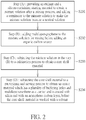
FIG. 2 is a flow chart of a method for fabricating an anode material of nano-silicon which has multilayer-graphene as a carrier and is coated with silicon suboxide and with an amorphous carbon layer of the present invention, -
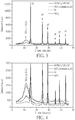
FIG. 3 is a perspective view of a schematic drawing illustrating a synchrotron X-ray diffraction (SXRD) pattern of Si/SiOx/MLG/C, SiOx (commercial), Si and SiO2 of the present invention, -
FIG. 4 is a perspective view of a schematic drawing illustrating a partial enlarged view ofFIG. 3 of the present invention, -
FIG. 5 is a perspective view of a schematic drawing illustrating an SEM image of the Si/SiOx/MLG/C sample of the invention and an EDS mapping image of (Si, C, O) of the present invention, -
FIG. 6 is a perspective view of a schematic drawing illustrating an SEM image of the SiOx (commercial) sample and an EDS mapping image of (Si, C, O) of the present invention, -
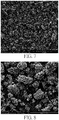
FIG. 7 is a perspective view of a schematic drawing illustrating an SEM image of the Si/SiOx/C sample (Example 2) of the present invention, -
FIG. 8 is a perspective view of a schematic drawing illustrating an SEM image of the Si/SiOx/MLG/C sample (Example 3) of the present invention, -
FIG. 9 is a perspective view of a schematic drawing illustrating a spectrum analysis of the XPS Si2p of the Si/SiOx/MLG/C of the present invention, -
FIG. 10 is a perspective view of a schematic drawing illustrating the spectrum analysis of the XPS Si2p of SiOx (commercial) of the present invention, -
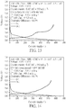
FIG. 11 is a perspective view of a schematic drawing illustrating a charging and discharging curve of a half-cell of the Si/SiOx/MLG/C material according to Example 3 of the present invention, -
FIG. 12 is a perspective view of a schematic drawing illustrating a charging and discharging curve of a half-cell of the comparative example 1 of the SiOx (commercial) material of the present invention, -
FIG. 13 is a schematic diagram illustrating a half-cell test of the 15 wt% Si/SiOx/MLG/C + 85 wt% MCMB material according to Example 5 of the present invention, -
FIG. 14 is a schematic diagram illustrating a half-cell test of 15 wt% SiOx (commercial) + 85 wt% MCMB material of the present invention, -
FIG. 15 is a schematic diagram illustrating a half-cell test chart of long charging and discharging cycle test of the material of Example 5 (15 wt% Si/SiOx/MLG/C + 85wt% MCMB) and the material of Comparative Example 3 (15 wt% SiOx (commercial) + 85 wt% MCMB) of the present invention. - Specific embodiments are provided to elaborate the practice of the invention. The advantages and efficacy thereof would be readily appreciated by persons of ordinary skill in the art from the disclosure of the invention.
- The theoretical capacity of silicon as an anode material is approximately 3500 mAh/g, and partial amount of addition is capable of greatly increasing the overall energy density of the anode of a battery. However, due to the volume expansion of Si as many as 4 times in the charging and discharging cycles, irreversible defects occur on the surface of silicon and result in drawbacks, such as a decrease in battery capacity, or lower Coulombic efficiency ... etc. One objective of the invention is to solve the above problems by using a structure containing Si/SiOx/MLG/C, whose outermost structure is SiOx along with amorphous carbon which is obtained from a thermal pyrolysis process of an organic carbon source to wrap Si/graphene inside the structure to form a core-shell structure. Such core-shell structure is capable of restricting the drastic volume expansion of silicon during the charging and discharging cycles, so that the silicon powder may not form major defects so as to maintain its conductive paths. The capacity of the anode material may be accordingly maintained within a given range. By changing the oxygen content on Si and controlling the graphene and the carbon layer, the capacity of the composite anode material which has nano-silicon wrapped inside of silicon suboxide and an amorphous carbon layer may be kept in a range of approximately 1600 mAh g-1 ∼ 1800 mAh g-1 which is comparable with that of a commercial product.
- Please refer to
FIG. 1. FIG. 1 is a perspective view of a schematic drawing illustrating an anode material of nano-silicon which has multilayer-graphene as a carrier and is coated with silicon suboxide and with an amorphous carbon layer. As shown inFIG. 1 , the invention provides an anode material of nano-silicon with multilayer-graphene to serve as a carrier. Both the nano-silicon and the multilayer-graphene are coated with silicon suboxide and with an amorphous carbon layer. The anode material of nano-silicon includes: multilayer-graphene 11 to serve as a carrier, nano-silicon 12 adsorbed on the multilayer-graphene 11 and both the multilayer-graphene 11 and the nano-silicon 12 serving as a core, a silicon suboxide and anamorphous carbon layer 13 to wrap the multilayer-graphene 11 and the nano-silicon 12, and a plurality of buffering holes 14 disposed on the anode material in order to provide sufficient buffering space. - Please refer to
FIG. 2. FIG. 2 illustrates a flow chart of a method for fabricating an anode material of nano-silicon which has multilayer-graphene as a carrier and is coated with silicon suboxide and with an amorphous carbon layer. As shown inFIG. 2 , the invention provides a method for fabricating an anode material of nano-silicon which has multilayer-graphene as a carrier and is coated with silicon suboxide and with an amorphous carbon layer. The method includes the steps of: - (A) providing an etchant and a silicon-containing starting material to obtain a mixture solution after a mixing process, and adding a terminator to the mixture solution to make the mixture solution become a neutral solution S201;
- (B) adding multilayer-graphene to the mixture solution for mixing before adding an organic carbon source S202;
- (C) subjecting the mixture solution in the step (B) to a calcination process to obtain a core shell material S203; and
- (D) subjecting the core shell material to a pulverizing and sieving process to obtain an anode material which has a plurality of buffering holes and multilayer-graphene as a carrier and is coated with silicon suboxide and with an amorphous carbon layer, before the core shell material is washed with a solvent S204.
- The [nano-silicon or SiOx or (nano-silicon and SiOx)] / multilayer-graphene / (silicon suboxide + amorphous carbon) anode material of the invention is mixed with a binder and with a conductive agent in a certain ratio to form a slurry then it is applied on a 10 µm copper foil. First, the solvent was dried at 80 °C and then it is baked in a vacuum oven at 110 °C for 24 hours to remove the solvent to obtain a finished electrode. The finished electrode is cut to form circular chips of 12 mm in diameter (12ϕ) for making CR2032 button-type lithium ion secondary batteries. The batteries are subjected to a capacity test of a half-cell (lithium metal as the counter electrode (15 mm diameter, 15ϕ)) which uses 1.0 M LiPF6 in an EC (ethylene carbonate) : FEC (fluoroethylene carbonate) : DMC (dimethyl carbonate) : EMC (ethylene methyl carbonate) = 28 : 7 : 10 : 55 composite solvent with additional additives of 1% VC (vinylene carbonate) and 1.5% PS (1,3-propane sultone). The machine model for measuring the capacity is BAT-750B.
- 500 mL of 0.25 mM NaOH solution is prepared and continuously stirred at 200 rpm. 25 g of 200 nm silicon powder is added to the above NaOH solution to undergo a reaction for 0.5 hour, and then citric acid is added and stirred as a terminator. The terminator is added to adjust the pH value to be 7 so that silicon stops reacting with NaOH. High temperature calcination is performed at 900 °C to carry out a carbonization treatment (calcination process). The obtained nano-silicon-based anode material (a structure of nano-silicon / (silicon suboxide + amorphous carbon)) is pulverized, grinded and sieved to mix the active materials: conductive agent: PAA: SBR: CMC at a proportion of 73:12:2.5:5.6:6.9 to form a slurry. In mixing, CMC is first mixed with PAA then the active materials and conductive agents are premixed by means of dry blending before they are added to the solution of CMC and PAA. At last, SBR is added and uniformly mixed. The obtained slurry is applied to a copper foil by doctor blade coating. This sample is called Si/SiOx/C-0.5h.
- 500 mL of 0.25 mM NaOH solution is prepared and continuously stirred at 200 rpm. 25 g of 200 nm silicon powder is added to the above NaOH solution to undergo a reaction for 4 hour, and then citric acid is added and stirred as a terminator. The terminator is added to adjust the pH value to be 7 so that silicon stops reacting with NaOH. High temperature calcination is performed at 900 °C to carry out a carbonization treatment (calcination process). The obtained nano-silicon-based anode material (a structure of nano-silicon / (silicon suboxide + amorphous carbon)) is pulverized, grinded and sieved to mix the active materials: conductive agent: PAA: SBR: CMC at a proportion of 73:12:2.5:5.6:6.9 to form a slurry. In mixing, CMC is first mixed with PAA then the active materials and conductive agents are premixed by means of dry blending before they are added to the solution of CMC and PAA. At last, SBR is added and uniformly mixed. The obtained slurry is applied to a copper foil by doctor blade coating. This sample is called Si/SiOx/C.
- 500 mL of 0.25 mM NaOH solution is prepared and continuously stirred at 200 rpm. 25 g of 200 nm silicon powder is added to the above NaOH solution to undergo a reaction for 4 hour, and then citric acid is added and stirred as a terminator. The terminator is added to adjust the pH value to be 7 so that silicon stops reacting with NaOH. Later 2.5 g of multi-layer graphene (MLG) is added and stirred for 12 hours to allow the nano-silicon powder effectively dispersed on MLG. High temperature calcination is performed at 900 °C to carry out a carbonization treatment (calcination process). The by-products, for example water-soluble salts such as Na2CO3, of the terminator and NaOH after calcination is washed off with deionized water after the obtained nano-silicon-based anode material (a structure of nano-silicon / (silicon suboxide + amorphous carbon)) is pulverized, grinded and sieved. The active materials: conductive agent: PAA: SBR: CMC are mixed at a proportion of 73:12:2.5:5.6:6.9 to form a slurry. In mixing, CMC is first mixed with PAA then the active materials and conductive agents are premixed by means of dry blending before they are added to the solution of CMC and PAA. At last, SBR is added and uniformly mixed. The obtained slurry is applied to a copper foil by doctor blade coating. This sample is called Si/SiOx/MLG/C.
- The anode material Si/SiOx/MLG/C of Example 3 (5%) is mixed with a commercial graphite material, mesocarbon microbeads (MCMB, 95%) to form a slurry (active materials: conductive agent: PAA: SBR: CMC are mixed at a proportion of 93:3:0.67:1.5:1.83), and then subjected to an electrode plate preparation and to a battery assembly process. This sample is called 5 wt% Si/SiOx/MLG/C + 95 wt% mesocarbon microbead (MCMB).
- The anode material Si/SiOx/MLG/C of Example 3 (15%) is mixed with a commercial graphite material, mesocarbon microbeads (MCMB, 85%) at a proportion shown in Example 4 to form a slurry, and then subjected to an electrode plate preparation and to a battery assembly process. This sample is called 15 wt% Si/SiOx/MLG/C + 85 wt% mesocarbon microbead (MCMB).
- Commercially available carbon-coated SiOx powder (0.8 < x < 0.95) is purchased to prepare electrode plates and a half-cell is assembled and subjected to tests in the same mixing process and proportion of Example 1. The results are compared with these of Example 3. This sample is called SiOx (commercial).
- The SiOx anode material of Comparative Example 1 is mixed with 95% of commercially available graphite material mesocarbon microbeads (the same proportion as in Example 4) to form a slurry, and then subjected to an electrode plate preparation and to a battery assembly process. Compared with Example 4, this sample is called 5 wt% SiOx (commercial) + 95 wt% MCMB.
- The SiOx anode material of Comparative Example 1 is mixed with 85% of commercially available graphite material mesocarbon microbeads (the same proportion as in Example 4) to form a slurry, and then subjected to an electrode plate preparation and to a battery assembly process. Compared with Example 5, this sample is called 15 wt% SiOx (commercial) + 85 wt% MCMB.
- Please refer to
FIG. 3. FIG. 3 is a perspective view of a schematic drawing illustrating a synchrotron X-ray diffraction (SXRD) pattern of Si/SiOx/MLG/C, SiOx (commercial), Si and SiO2 of the invention. Please refer toFIG. 4. FIG. 4 is a perspective view of a schematic drawing illustrating a partial enlarged view ofFIG. 3 of the invention. As shown in the drawings, the position at Si peak and intensity of Si/SiOx/MLG/C are very close to those of a standard Si with the difference that ∼120 is the diffraction peak of the amorphous phase of SiOx. The enlarged view ofFIG. 4 clearly shows that a standard Si still has some minor peaks of SiO2 here, which is confirmed by the comparison with a standard SiO2. The reason why there are still some observed signals of SiO2 on the standard Si is because nano-silicon tends to form a thin layer of native silicon oxide easily by oxidation in the atmosphere, and it is observed in the sample of Si/SiOx/MLG/C that the signal of SiO2 is much stronger than that of the Si standard, so it can be confirmed that this synthesis method can indeed turn a nano-silicon into a Si/SiOx composite sample. However, since X-ray is less sensitive to oxygen, the photoelectron spectroscopy (XPS) is instead needed to determine if it is SiO2 or SiOx. For the commercially available SiOx, it is an amorphous phase material composed of Si and SiO2. The current study of the structure of the material suggests that it is a two-phase material in which one Si atom may be simultaneously bonded to four neighbor Si atoms (Si phase) or to four neighbor O atoms (SiO2 phase). But some studies have also pointed out that SiOx is a mono-phase material in which Si-Si bonding and Si-O bonding are randomly distributed throughout the whole structure. It is known from the results of SXRD that the material Si/SiOx/MLG/C is indeed a material composed of amorphous phase SiOx and crystal phase of Si. - Please refer to
FIG. 5. FIG. 5 is a perspective view of a schematic drawing illustrating an SEM image of the Si/SiOx/MLG/C sample of the invention and an EDS mapping image of (Si, C, O) of the invention. Please refer toFIG. 6. FIG. 6 is a perspective view of a schematic drawing illustrating an SEM image of the SiOx (commercial) sample and an EDS mapping image of (Si, C, O). As shown in the drawing,FIG. 5 shows the SEM (scan electron microscope) image of the Si/SiOx/MLG/C and its EDS mapping results which contains the three elements of Si, C and O. With respect to the silicon element, it can be observed that it is evenly distributed on the particles, and further it can be observed that the oxygen element and the carbon element have a higher concentration at the outer periphery of the particles and in the core part the concentration of oxygen element and the carbon element is lower. Hence, it may be inferred along with the results of SXRD that the major material composition of the outer shell is C and SiOx while the major material composition in the inner core is Si, which verifies the concept of the core-shell material which is proposed by the invention. To be compared with the SiOx (commercial) sample inFIG. 6 , the EDS mapping results shows that C, Si, O are uniformly distributed on the particles with a relatively lower content of C because the commercial product is prepared by a high-temperature gas phase method and the composition of the entire material is uniform with the pulverization is finally carried out before the carbon coating is carried out. - Please refer to
FIG. 7. FIG. 7 is a perspective view of a schematic drawing illustrating an SEM image of the Si/SiOx/C sample (Example 2) of the invention. Please refer toFIG. 8. FIG. 8 illustrates an SEM image of the Si/SiOx/MLG/C sample (Example 3) of the invention. As shown in drawing, it can be clearly observed that the addition of MLG as a carrier of Si/SiOx in the process reduces the formation of finer powders, makes the slurry mixing process easier and makes the dispersion more uniform. Once peeling occurs, the electrode's capacity would be drastically reduced and the electrical impedance is increased. It can be observed from the comparison between Example 2 and Example 3 that the Coulombic efficiency in the first circle is improved because of the improvement of the dispersion so that Si/SiOx is less likely to crack or to peel during the charging and discharging process to improve the resultant Coulombic efficiency although the addition of MLG makes the reversible capacity of the Si/SiOx/MLG/C composite material decrease and the capacitance of the MLG itself is lower than that of Si/SiOx. - Please refer to
FIG. 9. FIG. 9 is a perspective view of a schematic drawing illustrating a spectrum analysis of the XPS Si2p of the Si/SiOx/MLG/C of the invention. Please refer toFIG. 10. FIG. 10 is a perspective view of a schematic drawing illustrating the spectrum analysis of the XPS Si2p of SiOx (commercial) of the invention. As shown in the drawing, the valences of Si on the surface of the sample of Si/SiOx/MLG/C are from Si0 to Si4+. The semi-quantitative analysis results of C, O, Si by XPS full spectrum scan of Table 2 show that the percentages in the Si/SiOx/MLG/C sample are 31%, 39%, 30%, but the percentages in the SiOx (commercial) sample are 87%, 10%, 3%. The large difference mainly resides in the XPS analysis mainly on the surface analysis (depth ∼10 nm). Because the SiOx (commercial) sample is prepared by a high-temperature gas phase method before the chemical vapor deposition carbon coating is carried out, more signals of carbon is detected by the analysis of the SiOx (commercial) sample. For the Si/SiOx/MLG/C sample, the contents of the surface composition of C, O, Si are close to one another because the material composition of the shell is SiOx/C. Further to analyze the valence distribution of Si2p individual peaks (Table 3), it is known from the calculated results of the analysis of different Si valences that the parameter x would be 1.56 if the material is averagely represented by an general formula SiOx. However, when reviewing the prior art references, it is estimated that the unit capacity per gram would be lower than 800 mAh g-1 for SiOx with x = 1.56 but the reversible capacity of the Si/SiOx/MLG/C sample from Table 1 is shown to be 1814 mAh g-1 so it is confirmed again that the sample is a composite material with an outer shell of SiOx/C and with an inner core of Si/MLG. On the contrary, for the SiOx (commercial) sample the main valence of Si is 2+ and x is 0.94 from the calculation of the valence analysis, which is pretty close to the oxygen content disclosed in the patent of the supplier.TABLE 1 Semi-quantitative analysis results of C, O, Si by XPS full spectrum scan Atomic % C O Si Si/SiOx/MLG/C 31% 39% 30% SiOx (commercial) 87% 10% 3% TABLE 2 Analysis of individual peaks of the valence distribution of XPS Si2p spectrum Si valence (Area %) Si0 Si1+ Si2+ Si3+ Si4+ SiOx Si/SiOx/MLG/C 7% 3% 9% 33% 48% SiO1.56 SiOx (commercial) 5% 0% 85% 9% 0% SiO0.94 - Please refer to
FIG. 11. FIG. 11 is a perspective view of a schematic drawing illustrating a test chart of a half-cell of the Si/SiOx/MLG/C material according to Example 3 of the invention. Please refer toFIG. 12. FIG. 12 is a perspective view of a schematic drawing illustrating a test chart of a half-cell of the comparative example 1 of the SiOx (commercial) material. As shown inFIG. 11, FIG. 11 consists of the 0.4 V redox characteristic platform of Si and the oblique rising line of SiOx, whileFIG. 10 shows the characteristic charging and discharging curve of SiOx (commercial), but the two materials have problems of low Coulombic efficiency and of poor battery life when used individually so only the first cycle Coulombic efficiency and the reversible capacitance are measured in the tests. A comparison of the two shows that the sample of Si/SiOx/MLG/C has a high reversible capacity (1814 mAh g-1) while the SiOx (commercial) sample has a commercially average capacity up to ∼1600 mAh g-1. The Coulombic efficiency of the Si/SiOx/MLG/C sample is slightly 2% lower. However, it is observed from the graphite-mixed test results in Table 1 that the first cycle Coulombic efficiency of the two samples is close to each other in spite of 5% mixing or of 15% mixing. Accordingly it is inferred that the Coulombic efficiency of the Si/SiOx/MLG/C sample is slightly lower than that of the SiOx (commercial) sample when Si/SiOx/MLG/C is used alone because there is no other graphite material to help suppress its volume expansion. The SiOx (commercial) has slightly higher Coulombic efficiency because there is a large amount of Li2O and Li4SiO4 to be helpful in suppressing its volume expansion when it is activated after the first circle. In accordance with these, from Table 3 it is known that each of the two materials has its own problem of lower first cycle Coulombic efficiency due to respective different reasons. For the SiOx (commercial), it needs addition lithium to form Li2O and Li4SiO4 at its first cycle. But for Si/SiOx/MLG/C, the first cycle Coulombic efficiency is lower owing to the volume expansion of its core Si to result in breaking or cracking. Surely, its outer shell of SiOx still consumes some of the lithium to form Li2O and Li4SiO4 to help suppress the volume expansion. By absorbing its volume expansion along with the mixed graphite, the first cycle Coulombic efficiency of Examples 4 and 5 and Comparative Examples 2 and 3 are similar. Further, the unit gram capacity of the anode material formed by mixing graphite of the same proportion is higher than that of the SiOx (commercial) sample because the Si/SiOx/MLG/C sample has a higher reversible capacity.Table 3 Tests of half-cells of the Si/SiOx/MLG/C materials in examples and of SiOx (commercial) sample. Composition of anode material Charging capacity of the first cycle (mAh g-1) Discharging capacity of the first cycle (mAh g-1) First cycle Coulombic efficiency (%) Residual capacity rate after 100 cycles (%) Example 1 Si/SiOx/C-0.5h 2986 1986 66.5 -* Example 2 Si/SiOx/C 2643 1914 72.4 -* Example 3 Si/SiOx/MLG/C 2329 1814 77.9 -* Example 4 5wt% Si/SiOx/MLG/C + 95 wt. % MCMB 470 427 90.9 93.1 Example 5 15wt% Si/SiOx/MLG/C + 85 wt % MCMB 644 570 88.5 80.3 Comparative Example 1 SiOx (commercial) 1983 1594 80.4 -* Comparative Example 2 5wt% SiOx (commercial) + 95wt% MCMB 450 411 91.3 88.4 Comparative Example 3 15wt% SiOx (commercial) + 85wt% MCMB 605 537 88.7 62.0 - Please refer to
FIG. 13. FIG. 13 is a perspective view of a schematic drawing illustrating a half-cell test chart of the 15 wt% Si/SiOx/MLG/C + 85 wt% MCMB material according to Example 5 of the invention. Please refer toFIG. 14. FIG. 14 is a perspective view of a schematic drawing illustrating a half-cell test chart of 15 wt% SiOx (commercial) + 85 wt% MCMB material of the invention. Please refer toFIG. 15. FIG. 15 is a perspective view of a schematic drawing illustrating a half-cell test chart of long charging and discharging cycle of the material of Example 5 (15 wt% Si/SiOx/MLG/C + 85wt% MCMB) and the material of Comparative Example 3 (15 wt% SiOx (commercial) + 85 wt% MCMB). As shown in drawing, as far as the capacity is concerned, silicon still has higher capacity contribution although only 15% of Si/SiOx/MLG/C or of SiOx (commercial) is mixed so the silicon-oxygen-based materials still dominate the charging-discharging curves. Due to the 85% graphite anode, it shows a better first cycle Coulombic efficiency and cycle life.FIG. 15 illustrates a half-cell test of long charging and discharging cycle of the material of Example 5 (15 wt% Si/SiOx/MLG/C + 85wt% MCMB) and the material of Comparative Example 3 (15 wt% SiOx (commercial) + 85 wt% MCMB) with 0.5 C current (1C = 550 mA g-1). Example 5 has better stability. After 5 cycles of 0.1 C charging and discharging cycles and 100 cycles of a long cycle test of 0.5 C, the capacity retention is still kept over 80%. However, for Comparative Example 3, under the same conditions, the capacity decreases more after 80 cycles at 0.5 C, and the capacity retention drops to only 62% after 100 cycles. - The anode material of the invention uses nano-Si as a raw material to undergo alkali etching and Si/SiOx are dispersed on the surface of the MLG by a wet dispersion method in the presence of a solvent, and finally it is coated with an organic pyrolysis carbon layer so that nano-Si can be uniformly distributed in the composite material. MLG along with SiOx slows down the volume expansion effect and cracking of Si which are caused by the charging and discharging cycles. 15% of the anode material with a commercial graphite anode material is physically mixed to form a slurry, to form an electrode and finally fabricated to be a CR2032 battery. The measured reversible capacity is about ∼570 mAh g-1 after testing, which is ∼1.6 time higher than that of a pure graphite anode material (∼350 mAh g-1) with the first circle Coulombic efficiency up to ∼ 89%, and its capacity retention is 80% after 100 cycles. Compared with commercial SiOx material, it has better capacity retention and advantages of process cost so it is suitable to serve as an anode material for the lithium ion batteries of high energy density.
Claims (15)
- An anode material of nano-silicon (12) having multilayer-graphene (11) as a carrier and coated with silicon suboxide and with an amorphous carbon layer (13), characterized by:multilayer-graphene (11) serving as a carrier;nano-silicon (12) adsorbed on the multilayer-graphene (11), both the multilayer-graphene (11) and the nano-silicon (12) serving as a core;silicon suboxide and an amorphous carbon layer (13) coated on the multilayer-graphene (11) and on the nano-silicon (12); anda plurality of buffering holes (14) disposed on the anode material to provide buffering space.
- The anode material of nano-silicon (12) having multilayer-graphene (11) as a carrier and coated with silicon suboxide and with an amorphous carbon layer (13) of Claim 1, characterized in that the nano-silicon (12) has a particle size in a range of 50 nm ∼ 300 nm.
- The anode material of nano-silicon (12) having multilayer-graphene (11) as a carrier and coated with silicon suboxide and with an amorphous carbon layer (13) of Claim 1, characterized in that the nano-silicon (12) is attached to the multilayer-graphene (11) by means of hydroxyl groups.
- The anode material of nano-silicon (12) having multilayer-graphene (11) as a carrier and coated with silicon suboxide and with an amorphous carbon layer (13) of Claim 1, characterized in that the amorphous carbon layer (13) is obtained from an organic carbon source through an organic pyrolysis process, and the organic carbon source is selected from a group consisting of glucose, sucrose, citric acid, polyvinyl alcohol, polyethylene glycol, polyacrylonitrile, asphalt, a phenolic resin, polyaniline, an epoxy resin, polyvinylpyrrolidone, and an unsaturated hydrocarbon gas.
- A method for fabricating an anode material having multilayer-graphene (11) as a carrier and coated with silicon suboxide and with an amorphous carbon layer (13), characterized by:providing an etchant and a silicon-containing starting material to obtain a mixture solution after a mixing process, and adding a terminator to the mixture solution to make the mixture solution become a neutral solution;adding multilayer-graphene (11) to the mixture solution for mixing before adding an organic carbon source;subjecting the mixture solution with the added multilayer-graphene (11) to a calcination process to obtain a core shell material; andsubjecting the core shell material to a pulverizing and sieving process to obtain an anode material which has a plurality of buffering holes (14) and multilayer-graphene (11) as a carrier and is coated with silicon suboxide and with an amorphous carbon layer (13), before the core shell material is washed with a solvent.
- The method for fabricating an anode material having multilayer-graphene (11) as a carrier and coated with silicon suboxide and with an amorphous carbon layer (13) of Claim 5, characterized in that the etchant is selected from a group consisting of a NaOH solution and a KOH solution.
- The method for fabricating an anode material having multilayer-graphene (11) as a carrier and coated with silicon suboxide and with an amorphous carbon layer (13) of Claim 5, characterized in that the silicon-containing starting material is selected from a group consisting of silicon powder and silicon suboxide powder.
- A method for fabricating an anode material having multilayer-graphene (11) as a carrier and coated with silicon suboxide and with an amorphous carbon layer (13) of Claim 5, characterized in that the solvent is selected from the group consisting of deionized water, glycerol, and ethanol.
- The method for fabricating an anode material having multilayer-graphene (11) as a carrier and coated with silicon suboxide and with an amorphous carbon layer (13) of Claim 5, characterized in that the terminator is selected from a group consisting of hydrochloric acid (HCl), nitric acid (HNO3), sulfuric acid (H2SO4), citric acid and acetic acid.
- The method for fabricating an anode material having multilayer-graphene (11) as a carrier and coated with silicon suboxide and with an amorphous carbon layer (13) of Claim 5, characterized in that the organic carbon source is selected from a group consisting of glucose, sucrose, citric acid, polyvinyl alcohol, polyethylene glycol, polyacrylonitrile, asphalt, a phenolic resin, polyaniline, an epoxy resin, polyvinylpyrrolidone, and an unsaturated hydrocarbon gas.
- The method for fabricating an anode material having multilayer-graphene (11) as a carrier and coated with silicon suboxide and with an amorphous carbon layer (13) of Claim 5, characterized in that a temperature range of the calcination process is 600 °C ∼ 1000 °C.
- The method for fabricating an anode material having multilayer-graphene (11) as a carrier and coated with silicon suboxide and with an amorphous carbon layer (13) of Claim 5, characterized in that a pulverizing procedure in the pulverizing and sieving process is selected from a group consisting of machining, ball milling and grinding.
- The method for fabricating an anode material having multilayer-graphene (11) as a carrier and coated with silicon suboxide and with an amorphous carbon layer (13) of Claim 5, characterized in that a sieve which is used in the pulverizing and sieving process has a mesh number between 80 mesh and 600 mesh.
- A method for fabricating an anode material having multilayer-graphene (11) as a carrier and coated with silicon suboxide and with an amorphous carbon layer (13) of Claim 5, characterized in that a binder, a conductive agent, a solvent and the anode material which has multilayer-graphene (11) as a carrier and is coated with silicon suboxide and with an amorphous carbon layer (13) are applied on a metal foil to prepare an anode electrode after mixed together.
- The method for fabricating an anode material having multilayer-graphene (11) as a carrier and coated with silicon suboxide and with an amorphous carbon layer (13) of Claim 5, characterized in that the binder is selected from a group consisting of PVDF, CMC, SBR, Alginate, Chitosan and LA132.
Applications Claiming Priority (1)
| Application Number | Priority Date | Filing Date | Title |
|---|---|---|---|
| TW107141138A TWI711208B (en) | 2018-11-16 | 2018-11-16 | Negative electrode material of silicon oxide and amorphous carbon layer coated with nanosilicon with multilayer graphene as carrier and preparation method thereof |
Publications (2)
| Publication Number | Publication Date |
|---|---|
| EP3653576A2 true EP3653576A2 (en) | 2020-05-20 |
| EP3653576A3 EP3653576A3 (en) | 2020-09-30 |
Family
ID=67253704
Family Applications (1)
| Application Number | Title | Priority Date | Filing Date |
|---|---|---|---|
| EP19185627.7A Withdrawn EP3653576A3 (en) | 2018-11-16 | 2019-07-11 | Anode material of nano-silicon having multilayer-graphene as carrier and coated with silicon suboxide and with amorphous carbon layer and method for fabricating the same |
Country Status (5)
| Country | Link |
|---|---|
| US (1) | US10879530B2 (en) |
| EP (1) | EP3653576A3 (en) |
| JP (1) | JP7154197B2 (en) |
| CN (1) | CN111200123A (en) |
| TW (1) | TWI711208B (en) |
Cited By (6)
| Publication number | Priority date | Publication date | Assignee | Title |
|---|---|---|---|---|
| CN111816862A (en) * | 2020-07-31 | 2020-10-23 | 广东凯金新能源科技股份有限公司 | A kind of highly stable silicon carbon anode material and preparation method thereof |
| CN115020689A (en) * | 2022-08-08 | 2022-09-06 | 溧阳天目先导电池材料科技有限公司 | Nano silicon-carbon composite material for secondary lithium battery and preparation method and application thereof |
| CN115895023A (en) * | 2022-10-13 | 2023-04-04 | 晋江市亿兴橡塑有限公司 | Organic silicon foamed sheet and preparation method thereof |
| JP2023549506A (en) * | 2020-11-13 | 2023-11-27 | イオノーベル,インコーポレイテッド | Method for manufacturing porous silicon |
| CN119098585A (en) * | 2024-09-06 | 2024-12-10 | 中国石油天然气股份有限公司长庆石化分公司 | A Ge-C composite mesophase carbon microsphere and its preparation method and application |
| EP4411874A4 (en) * | 2021-10-01 | 2026-03-18 | Resonac Corp | COMPOSITE PARTICLES, MANUFACTURING PROCESSES FOR THEM AND USES THEM |
Families Citing this family (16)
| Publication number | Priority date | Publication date | Assignee | Title |
|---|---|---|---|---|
| KR20230034323A (en) * | 2020-07-10 | 2023-03-09 | 가부시키가이샤 한도오따이 에네루기 켄큐쇼 | Electrodes, secondary batteries, mobile bodies, and electronic devices |
| DE112021003746T5 (en) * | 2020-07-14 | 2023-04-27 | Semiconductor Energy Laboratory Co., Ltd. | Electrode, secondary battery, moving object, electronic device, and a manufacturing method of an electrode for a lithium-ion secondary battery |
| TWI749650B (en) * | 2020-07-20 | 2021-12-11 | 中鋼碳素化學股份有限公司 | Electrode plate material of lithium-ion battery |
| CN112467137B (en) * | 2020-09-09 | 2022-07-12 | 珠海中科兆盈丰新材料科技有限公司 | Silicon-based graphene composite material |
| TWI755998B (en) * | 2020-12-28 | 2022-02-21 | 國家中山科學研究院 | Silicon carbon anode material coated with double-layer carbon and preparation method thereof |
| JP7727260B2 (en) * | 2021-03-31 | 2025-08-21 | 戸田工業株式会社 | Silicon-containing amorphous carbon material and its manufacturing method, and lithium-ion secondary battery |
| CN114566639B (en) * | 2022-01-17 | 2024-06-21 | 苏州科技大学 | SiO (silicon dioxide)xComposite material/C, preparation method and application thereof |
| WO2023177078A1 (en) * | 2022-03-17 | 2023-09-21 | 주식회사 엘지에너지솔루션 | Lithium secondary battery |
| CN117730433B (en) * | 2022-04-11 | 2026-01-06 | 宁德新能源科技有限公司 | Silicon-carbon composite materials, methods for preparing silicon-carbon composite materials, negative electrode plates and electrochemical devices |
| CN117239052A (en) * | 2022-06-10 | 2023-12-15 | 清华大学 | Lithium-ion battery anode |
| CN114864909A (en) * | 2022-06-13 | 2022-08-05 | 珠海冠宇电池股份有限公司 | Negative electrode material, negative plate comprising negative electrode material and battery |
| CN114975962A (en) * | 2022-06-24 | 2022-08-30 | 内蒙古瑞盛天然石墨应用技术研究院 | Method for preparing silicon carbon anode material using photovoltaic waste silicon powder and graphene oxide |
| KR20240109492A (en) * | 2023-01-04 | 2024-07-11 | 삼성에스디아이 주식회사 | Negative electrode for rechargeable lithium battery and rechargeable lithium battery including same |
| EP4660133A1 (en) * | 2023-02-02 | 2025-12-10 | Group14 Technologies, Inc. | Si-c composite particles, method for producing same, and use of same |
| CN116314716A (en) * | 2023-04-12 | 2023-06-23 | 安徽工业大学 | Preparation method and application of silicon-carbon anode material with double protective layer synthesized in one step |
| CN119181786A (en) * | 2024-09-10 | 2024-12-24 | 南京航空航天大学 | Graphite-silicon-based composite negative electrode material and preparation method thereof |
Family Cites Families (25)
| Publication number | Priority date | Publication date | Assignee | Title |
|---|---|---|---|---|
| JP4519592B2 (en) * | 2004-09-24 | 2010-08-04 | 株式会社東芝 | Negative electrode active material for non-aqueous electrolyte secondary battery and non-aqueous electrolyte secondary battery |
| GB2470056B (en) | 2009-05-07 | 2013-09-11 | Nexeon Ltd | A method of making silicon anode material for rechargeable cells |
| US10256458B2 (en) * | 2011-04-01 | 2019-04-09 | Georgia Tech Research Corporation | Curved two-dimensional nanocomposites for battery electrodes |
| KR101342601B1 (en) * | 2011-06-30 | 2013-12-19 | 삼성에스디아이 주식회사 | Negative active material, manufacturing method thereof, and lithium battery containing the material |
| US9972836B2 (en) * | 2013-04-27 | 2018-05-15 | Robert Bosch Gmbh | SiOx/Si/C composite material and process of producing thereof, and anode for lithium ion battery comprising said composite material |
| CN103326023A (en) | 2013-06-07 | 2013-09-25 | 浙江瓦力新能源科技有限公司 | High-performance lithium ion battery silicon-carbon cathode material and preparation method thereof |
| US10886526B2 (en) * | 2013-06-13 | 2021-01-05 | Zenlabs Energy, Inc. | Silicon-silicon oxide-carbon composites for lithium battery electrodes and methods for forming the composites |
| US9959947B2 (en) * | 2013-09-30 | 2018-05-01 | Samsung Electronics Co., Ltd. | Composite, carbon composite including the composite, electrode, lithium battery, electroluminescent device, biosensor, semiconductor device, and thermoelectric device including the composite and/or the carbon composite |
| CN104466185A (en) * | 2014-11-12 | 2015-03-25 | 中国科学院深圳先进技术研究院 | Silicon/carbon negative electrode composite material and preparation method thereof as well as lithium ion battery and negative electrode thereof |
| CN104916826B (en) * | 2015-07-03 | 2017-10-20 | 东莞市迈科科技有限公司 | A kind of graphene coated silicium cathode material and preparation method thereof |
| EP3133690A1 (en) | 2015-07-20 | 2017-02-22 | Commissariat A L'energie Atomique Et Aux Energies Alternatives | Silicon-carbon composite particulate material |
| CN106784640B (en) * | 2015-11-25 | 2020-05-26 | 北京有色金属研究总院 | Silicon-based composite negative electrode material for lithium ion battery, preparation method of silicon-based composite negative electrode material and lithium ion battery negative electrode containing silicon-based composite negative electrode material |
| JP6353517B2 (en) | 2015-12-30 | 2018-07-04 | 友達晶材股▲ふん▼有限公司AUO Crystal Corporation | Lithium battery negative electrode material and manufacturing method thereof |
| US20170222219A1 (en) * | 2016-01-28 | 2017-08-03 | Dong Sun | Ordered nano-porous carbon coating on silicon or silicon/graphene composites as lithium ion battery anode materials |
| DE102016202458A1 (en) * | 2016-02-17 | 2017-08-17 | Wacker Chemie Ag | Process for producing Si / C composite particles |
| CN106067547A (en) * | 2016-08-10 | 2016-11-02 | 深圳市贝特瑞新能源材料股份有限公司 | Carbon-coated nano 3 SiC 2/graphite alkene cracks carbon-coating composite, preparation method and the lithium ion battery comprising this composite |
| CN107845785B (en) * | 2016-09-19 | 2022-06-03 | 三星电子株式会社 | Porous silicon composite cluster, method of preparing the same, carbon composite thereof, and electrode, lithium battery and device each including the same |
| CN106848264A (en) | 2017-04-01 | 2017-06-13 | 江苏中天科技股份有限公司 | A kind of porous silicon oxide lithium ion battery negative material and preparation method thereof |
| CN107204445B (en) | 2017-05-26 | 2019-07-19 | 郑州中科新兴产业技术研究院 | A kind of lithium ion battery three-dimensional porous silicon-carbon cathode material and preparation method thereof |
| KR102487626B1 (en) * | 2017-07-12 | 2023-01-12 | 삼성에스디아이 주식회사 | Negative active material for rechargeable lithium battery and rechargeable lithium battery including same |
| CN107611394B (en) * | 2017-09-08 | 2020-04-14 | 成都硅宝科技股份有限公司 | Carbon-coated core-shell structure nano silicon/graphene composite negative electrode material and preparation method thereof |
| CN109638229A (en) | 2017-10-09 | 2019-04-16 | 珠海市三顺纳米新材料有限公司 | Silicon-carbon composite cathode material and preparation method thereof and lithium ion battery |
| CN108336342B (en) * | 2018-02-28 | 2020-10-13 | 宁波富理电池材料科技有限公司 | Si/SiOx/C composite negative electrode material, preparation method thereof and lithium ion battery |
| CN108630919A (en) | 2018-04-04 | 2018-10-09 | 合肥国轩高科动力能源有限公司 | A carbon-coated silicon/graphene composite and its preparation method and application |
| CN108878834A (en) * | 2018-06-28 | 2018-11-23 | 重庆大学 | A kind of preparation method of graphene/silicon/carbon compound cathode materials |
-
2018
- 2018-11-16 TW TW107141138A patent/TWI711208B/en active
- 2018-12-13 US US16/218,486 patent/US10879530B2/en active Active
-
2019
- 2019-07-11 EP EP19185627.7A patent/EP3653576A3/en not_active Withdrawn
- 2019-07-30 CN CN201910693006.4A patent/CN111200123A/en active Pending
- 2019-08-15 JP JP2019149106A patent/JP7154197B2/en active Active
Cited By (8)
| Publication number | Priority date | Publication date | Assignee | Title |
|---|---|---|---|---|
| CN111816862A (en) * | 2020-07-31 | 2020-10-23 | 广东凯金新能源科技股份有限公司 | A kind of highly stable silicon carbon anode material and preparation method thereof |
| JP2023549506A (en) * | 2020-11-13 | 2023-11-27 | イオノーベル,インコーポレイテッド | Method for manufacturing porous silicon |
| EP4411874A4 (en) * | 2021-10-01 | 2026-03-18 | Resonac Corp | COMPOSITE PARTICLES, MANUFACTURING PROCESSES FOR THEM AND USES THEM |
| CN115020689A (en) * | 2022-08-08 | 2022-09-06 | 溧阳天目先导电池材料科技有限公司 | Nano silicon-carbon composite material for secondary lithium battery and preparation method and application thereof |
| CN115895023A (en) * | 2022-10-13 | 2023-04-04 | 晋江市亿兴橡塑有限公司 | Organic silicon foamed sheet and preparation method thereof |
| CN115895023B (en) * | 2022-10-13 | 2023-06-23 | 晋江市亿兴橡塑有限公司 | Organic silicon foaming sheet and preparation method thereof |
| CN119098585A (en) * | 2024-09-06 | 2024-12-10 | 中国石油天然气股份有限公司长庆石化分公司 | A Ge-C composite mesophase carbon microsphere and its preparation method and application |
| CN119098585B (en) * | 2024-09-06 | 2025-10-21 | 中国石油天然气股份有限公司长庆石化分公司 | A Ge-C composite mesophase carbon microsphere and its preparation method and application |
Also Published As
| Publication number | Publication date |
|---|---|
| US10879530B2 (en) | 2020-12-29 |
| CN111200123A (en) | 2020-05-26 |
| TWI711208B (en) | 2020-11-21 |
| TW202021179A (en) | 2020-06-01 |
| JP2020087910A (en) | 2020-06-04 |
| EP3653576A3 (en) | 2020-09-30 |
| JP7154197B2 (en) | 2022-10-17 |
| US20200194787A1 (en) | 2020-06-18 |
Similar Documents
| Publication | Publication Date | Title |
|---|---|---|
| EP3653576A2 (en) | Anode material of nano-silicon having multilayer-graphene as carrier and coated with silicon suboxide and with amorphous carbon layer and method for fabricating the same | |
| CN118630167B (en) | Anode materials and their preparation methods, electrochemical devices and electronic devices | |
| JP7392151B2 (en) | Secondary batteries, battery modules, battery packs, and devices containing the secondary batteries | |
| JP5680191B2 (en) | Composite hard carbon negative electrode material for lithium ion battery and manufacturing method thereof | |
| WO2020187040A1 (en) | Anode material, and electrochemical device and electronic device using the same | |
| KR101368474B1 (en) | Negative active material for rechargeable lithium battery, method of preparing the same, and rechargeable lithium battery including the same | |
| WO2024108771A1 (en) | Hard carbon negative electrode material and preparation method therefor, mixed negative electrode material, and secondary battery | |
| KR101442318B1 (en) | Anode active material for lithium secondary battery using silicon-carbon core-shell and manufacturing method thereof | |
| JP6592603B2 (en) | Negative electrode active material, mixed negative electrode active material, and method for producing negative electrode active material | |
| KR20150063620A (en) | Negative active material for rechargeable lithium battery, method of preparing the same, and rechargeable lithium battery including the same | |
| KR101919524B1 (en) | Negative electrode active material for rechargeable lithium battery, method of preparing of the same and rechargeable lithium battery including the same | |
| JP2016152077A (en) | Negative electrode active material for nonaqueous electrolyte secondary battery, nonaqueous electrolyte secondary battery, and method for manufacturing negative electrode material for nonaqueous electrolyte secondary battery | |
| EP3467912A1 (en) | Negative electrode active material, mixed negative electrode active material, and method for producing negative electrode active material | |
| JP2016526257A (en) | Conductive carbon for lithium-ion batteries | |
| EP3467911A1 (en) | Negative electrode active material, mixed negative electrode active material, and method for producing negative electrode active material | |
| WO2022270539A1 (en) | Composite carbon particles and use thereof | |
| EP3467913A1 (en) | Negative electrode active material, mixed negative electrode active material, and method for producing negative electrode active material | |
| EP3561921A1 (en) | Lithium ion secondary battery | |
| CN102633300A (en) | Carbon-coated lithium titanate cathode material as well as preparation method and applications thereof | |
| CN114026713A (en) | Silicon-carbon composite particle, negative electrode active material, and negative electrode, electrochemical device, and electronic device comprising same | |
| EP4060767A1 (en) | Negative electrode material, electrochemical device including same, and electronic device | |
| KR102176590B1 (en) | Method of preparing anode active material for rechargeable lithium battery and rechargeable lithium battery | |
| KR101660151B1 (en) | Anode for secondary battery, method for producing same, and secondary battery | |
| JP7810050B2 (en) | Transition metal composite oxide powder, electrode for power storage device using same, and power storage device | |
| EP4340088A1 (en) | Silicon-based negative electrode material, preparation method therefor and application thereof |
Legal Events
| Date | Code | Title | Description |
|---|---|---|---|
| PUAI | Public reference made under article 153(3) epc to a published international application that has entered the european phase |
Free format text: ORIGINAL CODE: 0009012 |
|
| STAA | Information on the status of an ep patent application or granted ep patent |
Free format text: STATUS: THE APPLICATION HAS BEEN PUBLISHED |
|
| AK | Designated contracting states |
Kind code of ref document: A2 Designated state(s): AL AT BE BG CH CY CZ DE DK EE ES FI FR GB GR HR HU IE IS IT LI LT LU LV MC MK MT NL NO PL PT RO RS SE SI SK SM TR |
|
| AX | Request for extension of the european patent |
Extension state: BA ME |
|
| PUAL | Search report despatched |
Free format text: ORIGINAL CODE: 0009013 |
|
| AK | Designated contracting states |
Kind code of ref document: A3 Designated state(s): AL AT BE BG CH CY CZ DE DK EE ES FI FR GB GR HR HU IE IS IT LI LT LU LV MC MK MT NL NO PL PT RO RS SE SI SK SM TR |
|
| AX | Request for extension of the european patent |
Extension state: BA ME |
|
| RIC1 | Information provided on ipc code assigned before grant |
Ipc: C01B 33/113 20060101ALI20200825BHEP Ipc: H01M 4/38 20060101ALI20200825BHEP Ipc: H01M 4/36 20060101ALI20200825BHEP Ipc: B82Y 30/00 20110101ALI20200825BHEP Ipc: C01B 32/194 20170101AFI20200825BHEP |
|
| STAA | Information on the status of an ep patent application or granted ep patent |
Free format text: STATUS: REQUEST FOR EXAMINATION WAS MADE |
|
| 17P | Request for examination filed |
Effective date: 20201124 |
|
| RBV | Designated contracting states (corrected) |
Designated state(s): AL AT BE BG CH CY CZ DE DK EE ES FI FR GB GR HR HU IE IS IT LI LT LU LV MC MK MT NL NO PL PT RO RS SE SI SK SM TR |
|
| STAA | Information on the status of an ep patent application or granted ep patent |
Free format text: STATUS: EXAMINATION IS IN PROGRESS |
|
| 17Q | First examination report despatched |
Effective date: 20210204 |
|
| STAA | Information on the status of an ep patent application or granted ep patent |
Free format text: STATUS: THE APPLICATION IS DEEMED TO BE WITHDRAWN |
|
| 18D | Application deemed to be withdrawn |
Effective date: 20230610 |