EP3653508B1 - Grenzschichtaufnahmegebläsesystem - Google Patents
Grenzschichtaufnahmegebläsesystem Download PDFInfo
- Publication number
- EP3653508B1 EP3653508B1 EP19204330.5A EP19204330A EP3653508B1 EP 3653508 B1 EP3653508 B1 EP 3653508B1 EP 19204330 A EP19204330 A EP 19204330A EP 3653508 B1 EP3653508 B1 EP 3653508B1
- Authority
- EP
- European Patent Office
- Prior art keywords
- hub
- blade
- fan
- percent
- tip
- Prior art date
- Legal status (The legal status is an assumption and is not a legal conclusion. Google has not performed a legal analysis and makes no representation as to the accuracy of the status listed.)
- Active
Links
Images


Classifications
-
- F—MECHANICAL ENGINEERING; LIGHTING; HEATING; WEAPONS; BLASTING
- F02—COMBUSTION ENGINES; HOT-GAS OR COMBUSTION-PRODUCT ENGINE PLANTS
- F02K—JET-PROPULSION PLANTS
- F02K5/00—Plants including an engine, other than a gas turbine, driving a compressor or a ducted fan
-
- B—PERFORMING OPERATIONS; TRANSPORTING
- B64—AIRCRAFT; AVIATION; COSMONAUTICS
- B64C—AEROPLANES; HELICOPTERS
- B64C11/00—Propellers, e.g. of ducted type; Features common to propellers and rotors for rotorcraft
- B64C11/001—Shrouded propellers
-
- B—PERFORMING OPERATIONS; TRANSPORTING
- B64—AIRCRAFT; AVIATION; COSMONAUTICS
- B64C—AEROPLANES; HELICOPTERS
- B64C21/00—Influencing air flow over aircraft surfaces by affecting boundary layer flow
- B64C21/01—Boundary layer ingestion [BLI] propulsion
-
- B—PERFORMING OPERATIONS; TRANSPORTING
- B64—AIRCRAFT; AVIATION; COSMONAUTICS
- B64C—AEROPLANES; HELICOPTERS
- B64C7/00—Structures or fairings not otherwise provided for
- B64C7/02—Nacelles
-
- B—PERFORMING OPERATIONS; TRANSPORTING
- B64—AIRCRAFT; AVIATION; COSMONAUTICS
- B64D—EQUIPMENT FOR FITTING IN OR TO AIRCRAFT; FLIGHT SUITS; PARACHUTES; ARRANGEMENT OR MOUNTING OF POWER PLANTS OR PROPULSION TRANSMISSIONS IN AIRCRAFT
- B64D27/00—Arrangement or mounting of power plants in aircraft; Aircraft characterised by the type or position of power plants
- B64D27/02—Aircraft characterised by the type or position of power plants
- B64D27/30—Aircraft characterised by electric power plants
- B64D27/33—Hybrid electric aircraft
-
- F—MECHANICAL ENGINEERING; LIGHTING; HEATING; WEAPONS; BLASTING
- F01—MACHINES OR ENGINES IN GENERAL; ENGINE PLANTS IN GENERAL; STEAM ENGINES
- F01D—NON-POSITIVE DISPLACEMENT MACHINES OR ENGINES, e.g. STEAM TURBINES
- F01D5/00—Blades; Blade-carrying members; Heating, heat-insulating, cooling or antivibration means on the blades or the members
- F01D5/12—Blades
- F01D5/14—Form or construction
- F01D5/141—Shape, i.e. outer, aerodynamic form
-
- B—PERFORMING OPERATIONS; TRANSPORTING
- B64—AIRCRAFT; AVIATION; COSMONAUTICS
- B64C—AEROPLANES; HELICOPTERS
- B64C2230/00—Boundary layer controls
-
- B—PERFORMING OPERATIONS; TRANSPORTING
- B64—AIRCRAFT; AVIATION; COSMONAUTICS
- B64C—AEROPLANES; HELICOPTERS
- B64C2230/00—Boundary layer controls
- B64C2230/04—Boundary layer controls by actively generating fluid flow
-
- F—MECHANICAL ENGINEERING; LIGHTING; HEATING; WEAPONS; BLASTING
- F05—INDEXING SCHEMES RELATING TO ENGINES OR PUMPS IN VARIOUS SUBCLASSES OF CLASSES F01-F04
- F05D—INDEXING SCHEME FOR ASPECTS RELATING TO NON-POSITIVE-DISPLACEMENT MACHINES OR ENGINES, GAS-TURBINES OR JET-PROPULSION PLANTS
- F05D2220/00—Application
- F05D2220/30—Application in turbines
- F05D2220/36—Application in turbines specially adapted for the fan of turbofan engines
-
- F—MECHANICAL ENGINEERING; LIGHTING; HEATING; WEAPONS; BLASTING
- F05—INDEXING SCHEMES RELATING TO ENGINES OR PUMPS IN VARIOUS SUBCLASSES OF CLASSES F01-F04
- F05D—INDEXING SCHEME FOR ASPECTS RELATING TO NON-POSITIVE-DISPLACEMENT MACHINES OR ENGINES, GAS-TURBINES OR JET-PROPULSION PLANTS
- F05D2270/00—Control
- F05D2270/01—Purpose of the control system
- F05D2270/17—Purpose of the control system to control boundary layer
-
- Y—GENERAL TAGGING OF NEW TECHNOLOGICAL DEVELOPMENTS; GENERAL TAGGING OF CROSS-SECTIONAL TECHNOLOGIES SPANNING OVER SEVERAL SECTIONS OF THE IPC; TECHNICAL SUBJECTS COVERED BY FORMER USPC CROSS-REFERENCE ART COLLECTIONS [XRACs] AND DIGESTS
- Y02—TECHNOLOGIES OR APPLICATIONS FOR MITIGATION OR ADAPTATION AGAINST CLIMATE CHANGE
- Y02T—CLIMATE CHANGE MITIGATION TECHNOLOGIES RELATED TO TRANSPORTATION
- Y02T50/00—Aeronautics or air transport
- Y02T50/10—Drag reduction
-
- Y—GENERAL TAGGING OF NEW TECHNOLOGICAL DEVELOPMENTS; GENERAL TAGGING OF CROSS-SECTIONAL TECHNOLOGIES SPANNING OVER SEVERAL SECTIONS OF THE IPC; TECHNICAL SUBJECTS COVERED BY FORMER USPC CROSS-REFERENCE ART COLLECTIONS [XRACs] AND DIGESTS
- Y02—TECHNOLOGIES OR APPLICATIONS FOR MITIGATION OR ADAPTATION AGAINST CLIMATE CHANGE
- Y02T—CLIMATE CHANGE MITIGATION TECHNOLOGIES RELATED TO TRANSPORTATION
- Y02T50/00—Aeronautics or air transport
- Y02T50/60—Efficient propulsion technologies, e.g. for aircraft
Definitions
- This disclosure relates to boundary layer fan systems for aircraft.
- Boundary layer ingestion (often abbreviated to BLI) is a technique that may be used to improve aircraft propulsive efficiency by reducing downstream wake and jet mixing losses. In practice a designer must try and exploit this benefit without adding excessive weight, drag or inefficiency into the aircraft or propulsion system.
- Equation 5 may be interpreted with and without boundary layer ingestion.
- United States patent application US2018050811 discloses a propulsion system for an aircraft which includes a gas turbine engine and an electric propulsion engine defining a central axis.
- the electric propulsion engine includes an electric motor and a fan rotatable about the central axis of the electric propulsion engine by the electric motor.
- the electric propulsion engine additionally includes a bearing supporting rotation of the fan and a thermal management system including a thermal fluid circulation assembly.
- the thermal fluid circulation assembly is in thermal communication with at least one of the electric motor or the bearing and is further in thermal communication with a heat exchanger of a thermal management system of the gas turbine engine.
- European patent application EP3048042 discloses a gas-electric propulsion system for an aircraft.
- the system includes a turbofan jet engine, an electric powered boundary layer ingestion fan that is coupled to a fuselage portion of the aircraft aft of the turbofan jet engine, and an electric generator that is electronically coupled to the turbofan jet engine and to the boundary layer ingestion fan.
- the electric generator converts rotational energy from the turbofan jet engine to electrical energy and provides at least a portion of the electrical energy to the boundary layer ingestion fan.
- EP3378780 discloses a boundary layer ingestion engine comprising a fan, the fan comprising a disc and a plurality of blades integrally formed with the disc.
- European patent application EP3026214 discloses an aerofoil in a gas turbine engine which has a spanwise distribution of maximum thicknesses of chordwise cross-sections of the aerofoil.
- the spanwise distribution of maximum thicknesses decreases from the root to the tip.
- the spanwise distribution is stepped between a first portion extending from the root and a second portion extending to the tip.
- United States patent application US5957661 discloses an axial flow fan which includes a hub, fan blades and a circular band.
- the hub rotates about a rotational axis when torque is applied from a shaft rotatably driven by a power source.
- the circular band is concentric with the hub, connected to the tip of each blade, and is spaced radially outward from the hub.
- the blades are configured to produce an airflow when rotated about the rotational axis.
- Each blade has a chord length distribution, stagger angle and dihedral distribution which varies along the length of the blade. The dihedral distance of each blade varies as a function of blade radius from the rotational axis.
- United States patent application US2003194327 discloses a method for determining the camber line and the thickness distribution for the blades used in fans having counter-rotating impellers.
- a boundary layer ingestion fan system for location aft of the fuselage of an aircraft, comprising:
- Such a fan exhibits the requisite distortion tolerance for operation in such an installation.
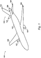
- a tube-and-wing-configuration aircraft 101 according to an embodiment is shown in Figure 1 .
- the aircraft 101 comprises a fuselage 102 with a conventional empennage 103 mounted thereto.
- both the tailplane 104 and vertical stabiliser 105 are mounted to the fuselage 102.
- the aircraft 101 further comprises a BLI fan system 106 mounted aft of the fuselage 103 and the empennage 103.
- the aircraft 101 is a twinjet and thus comprises two turbofan engines 107 mounted under a respective wing 108. It will be appreciated however that a greater number of engines may be provided depending upon the aircraft configuration. Further, a different engine configuration such as open rotor may be used.
- FIG. 2 A schematic of the propulsion system of the aircraft 101 is shown in Figure 2 .
- the BLI fan system 106 comprises a fan that is electrically-driven.
- the turbofan engines 107 therefore each comprise an electric machine 201 configured to generate electrical power for distribution to an electric machine 202 to drive the BLI fan system 106.
- each electric machine 201 is configured to generate 1 megawatt of electrical power for the BLI fan system 106.
- the electric machine 202 is configured to drive the BLI fan system 106 with 2 megawatts of electrical power.
- different amounts of electrical power may be produced by the electric machines 201 to, for example, power services on the aircraft 101.
- the electric machine 202 may be configured to drive the BLI fan system 106 with different amounts of power, such as greater than 2 megawatts or less than 2 megawatts depending upon the design point.
- the BLI fan system 106 shares its rotational axis A-A with the centreline of the aircraft 101 in the plane of Figure 2 .
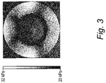
- Figure 3 shows the pressure field during cruise at B-B of Figure 2 .
- the lightest shade corresponds to an absolute total pressure of 32 kilopascals
- the darkest shade corresponds to an absolute total pressure of 20 kilopascals.
- the image of Figure 3 was generated by application of computational fluid dynamics to a three-dimensional model of the aircraft 101.
- the non-uniformity of the pressure distribution is due to the configuration of the empennage 103. Whilst a T-tail empennage may reduce the variation around below the 3 and 9 o'clock positions, this would come with all of the attendant disadvantages of such a configuration in terms of risk of entering deep stall, greater weight, lack of maintainability, etc. Further, there would still be a large degree of variation in the pressure field at the 12 o'clock position due to the continued presence of a vertical stabiliser.
- Figures 4A, 4B, and 4C set out the nomenclature that will be used to describe the design parameters of the fan in the BLI fan system 106. Reference is made in these Figures to the properties of a purely exemplary blade 401 which could form part of a turbomachine rotor stage. It will be appreciated that these Figures are purely to aid the reader and are not representative of any embodiments.
- Figure 4A is a meridional view of the exemplary blade 401.
- the blade 401 rotates around a rotational axis C-C.
- the blade 401 extends in span from a root at a hub 402 to a tip 403 adjacent an end wall 404.
- the hubline of the hub 402 has a hade angle ⁇ relative to the direction of the rotational axis C-C.
- the hub 402 has a positive hade angle ⁇ which is typical for compressors.
- the end wall 404 falls in the direction of arrow D, again this is typical for compressors.
- the blade 401 has a leading edge 405 and a trailing edge 406.
- all span positions r of the blade 401 are between 0 percent and 100 percent span, i.e. r ⁇ [0, 1].
- a particular span position r may vary in actual radial distance from the rotational axis C-C with axial position, due to hub hade angle ⁇ and the profile of the tip 403 to conform with the end wall 404. This is conventional.
- the hub-tip ratio of the rotor stage is defined by the ratio of the diameter of the hub 402 at the leading edge 405 (d hub ), to the diameter of the tip 403 at the leading edge 405 (d tip ), i.e. d hub /d tip .
- Figure 4B shows a cross section of the blade 401 in the axial-circumferential plane at a particular span position r.
- the blade 401 has a pressure surface 411 and a suction surface 412.
- the pressure surface 411 and the suction surface 412 define a camber line 413 halfway therebetween extending from the leading edge 405 to the trailing edge 406.
- a chord 414 is defined as a straight line connecting the ends of the camber line 413.
- the chord 414 has a chord length c.
- the blade 401 has a maximum thickness t, which is normal to the chord 414 and which is the maximum distance between the pressure surface 411 and the suction surface 412.
- chord length c and thickness t and the shape of the camber line 413 may vary with span r.
- Figure 4C shows a cascade of three blades 401 forming part of the same rotor stage at a particular span position r.
- a blade inlet angle ⁇ 1 is defined as the angle between the axial, defined by the rotational axis C-C, and the angle of the camber line 413 at the leading edge 405 of the blade 401.
- a stagger angle ⁇ is defined as the angle between the axial and the chord 414.
- a pitch s is defined as the circumferential distance between the camber lines 413 of each blade 401.
- a solidity ⁇ is defined as the ratio of chord length to pitch, i.e. c/s.
- a throat area A t is defined as the distance between the chord 414 of each blade in the cascade, in the direction perpendicular to the chord 414.
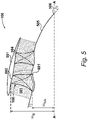
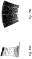
- FIG. 5 A meridional view of an embodiment of the BLI fan system 106 is shown in Figure 5 .
- the BLI fan system 106 is substantially axisymmetric around axis A-A.
- the BLI fan system 106 comprises a nacelle 501 which defines a duct 502. Boundary layer flow from the fuselage 102 enters the duct 502 in the direction of arrow E. A fan 503 is located within the duct 502. Details of the drive arrangement for the fan are omitted for clarity. In this example, an outlet guide vane set 504 is also provided and in a specific embodiment provide a structural support for the nacelle 501. Dashed lines indicating constant span positions r are included.
- the annulus lines of the duct 502 in the region of the outlet guide vane set 504 forms a contracting exit nozzle for the BLI fan system 106.
- the flow is accelerated over the outlet guide vanes. This can substantially reduce losses therein by keeping the flow attached.
- Such an approach cannot normally be taken in a typical turbofan due to the location of the gas turbine core radially inward of the bypass duct.
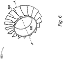
- the fan has a hub 601 that is arranged to rotate around axis A-A, and a plurality of identical fan blades 602 attached to the hub 601.
- the hade angle ⁇ of the hub 601 at an axial position coincident with the leading edge of the fan blades 602 is negative, i.e. it has a falling hubline.
- the hade angle ⁇ is set to match the boat tail angle of the fuselage 102.
- the hade angle ⁇ is between -10 and -20 degrees with respect to the rotational axis A-A. It will be appreciated by those skilled in the art that the hade angle ⁇ in a turbofan is almost always positive over the full axial extent of the root of the fan blades therein.
- the fan blades 602 employ leading edge sweep to reduce the loading in the hub.
- the hub-tip ratio of the fan 503 is from 0.45 to 0.55. This is substantially greater than typical turbofan fans, where the hub-tip ratio is typically less than 0.3.
- the higher hub-tip ratio of the fan 503 increases the blade speed in the hub for a fixed tip Mach number, which reduces hub diffusion to tolerable levels in this application.
- the hub-tip ratio of the fan 503 is 0.5.
- an afterbody 505 axially downstream of the nacelle 501.
- the afterbody 505 tapers to an apex 506 at the rotational axis A-A.
- the apex angle ⁇ of the afterbody 505, which is the angle the afterbody makes with the rotational axis A-A at the apex 506, is from 35 to 45 degrees. This is substantially higher than found in gas turbines, and allows for a much shorter, and therefore less lossy and lighter afterbody. This is tolerable due to the lower Mach numbers at the exit of the duct 502 than would be found in a gas turbine engine where the flow over the afterbody emanates from the low-pressure turbine exit.
- the apex angle ⁇ is 40 degrees.
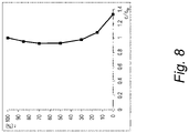
- the fan blades 602 have a ratio of the chord length at the 0 percent span position, c hub to the chord length at the 100 percent span position, c tip of one or greater. This assists in terms of improving distortion tolerance. It should be noted that this is markedly different from a typical modern turbofan fan blade in which the ratio of c hub to c tip is significantly less than unity due to the use of wide chord blades and the relatively benign pressure distribution.
- the ratio of c hub to c tip is 1.25 or greater. In particular it is 1.33 times greater. Further, embodiments of the fan blades 602 may observe the condition that the ratio of chord lengths, c between the 0 and 25 percent span positions to c tip be one or greater. This further improves distortion tolerance.
- the ratio of chord lengths, c between the 75 and 100 percent span positions to c tip is one or less.
- Figure 8 is a plot of the ratio of c to c tip with respect to the full range of span positions r for a specific embodiment of the fan blade 602.
- the fan blades 602 have a stagger angle at the 0 percent span position, ⁇ hub of 40 degrees or greater. This is compared to a typical turbofan fan blade which will tend to have a much lower or indeed zero stagger at the root to, amongst other things, reduce the inlet relative Mach number.
- the pressure distribution of the inlet flow for the BLI fan system 106 is markedly different to the freestream flow encountered by a turbofan in a traditional under-the-wing installation.
- stagger angle at the root is specified in the present embodiment to increase the distortion tolerance of the fan 503 by making its characteristics steeper and damping out the variations in inlet stagnation pressure.
- Such levels of stagger are acceptable as the axial velocity of the boundary layer along the fuselage 102 of the aircraft 101 is very low.
- ⁇ hub is chosen to be 60 degrees or less (down to the 40 degree minimum specified above).
- Figures 7B and 7C in an embodiment the condition of the stagger angle ⁇ being 40 degrees or greater is maintained for the full span of the blade.
- Figures 7B and 7C also exemplify the possibility of the condition of the stagger angle ⁇ being 60 degrees or less being maintained for the full span of the blade.
- Figure 9 is a plot of the stagger angle ⁇ with respect to the full range of span positions r for a specific embodiment of the fan blade 602.
- the ratio of blade thickness at the 0 percent span position, t hub to chord length at the 0 percent span position, c hub is 0.1 or greater. This may be observed in Figure 7A . This improves the amount of forcing that the blades can withstand.
- the ratio of blade thickness at the 100 percent span position, t tip to chord length at the 100 percent span position, c tip is 0.02 or less. This may be observed in Figure 7C . This reduces losses and improves efficiency.
- Figure 10 is a plot of the ratio of blade thickness, t to chord length, c with respect to the full range of span positions r for a specific embodiment of the fan blade 602.
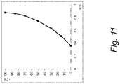
- Figure 11 is a plot of ratio of pitch, s to chord length, c with respect to the full range of span positions r for the specific embodiment of the fan 503 illustrated in Figure 6 .
- This specific embodiment has nineteen fan blades 602 which, along with the hub-tip ratio and overall diameter of the fan 503, sets the pitch s for a given span position r.
- the ratio of s to c is low at the 0 percent span position, which indicates that there will be a degree of interference between each blade. However, towards the tip the ratio of s to c tends towards unity which indicates lower interference.
- the choice of distribution in this manner optimises distortion tolerance and efficiency.
- the blade blockage which is the ratio of the blade thickness to the product of the circumferential pitch and the cosine of a blade inlet angle (t/s ⁇ cos ⁇ 1 ), is set to 0.25 or greater at the 0 percent span position.
- the blade blockage is 0.4 or greater at the 0 percent span position.
- the blade blockage may be 0.5 or greater at the 0 percent span position.
- the blade blockage may be 0.6 or greater at the 0 percent span position. Whilst it will be appreciated that higher degrees of blade blockage reduce the efficiency of the fan 503, the higher levels of blockage improve the distortion tolerance and ability to tolerate the amount of forcing on the blades.
- blade blockage of 0.25 or greater between the 0 and 25 percent span positions. Additionally or alternatively the blade blockage may be 0.4 or greater between the 0 and 10 percent span positions.
- Figure 12 is a plot of the blade blockage, t/s ⁇ cos ⁇ 1 with respect to the full range of span positions r for the specific embodiment of the fan 503.
- the present embodiment of the fan 503 brings together the full set of the geometric parameters set out in Figures 8 to 12 .
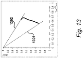
- a Smith chart for the fan 503 at its design point is shown in Figure 13 .
- the characteristic for each section can be predicted as a line passing through (0,1) and the design point on the Smith chart.
- the tip characteristic is predicted as line 1301
- the hub characteristic is predicted as line 1302.
- both characteristics have a negative gradient which is indicative of high distortion tolerance and high stall margin.
- a typical turbofan fan will have a hub characteristic with a positive gradient, which would indicate that it would have low stall margin and low distortion tolerance.
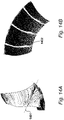
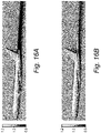
- FIG. 16A and 16B A comparison of the pressure field around the aircraft 101 and a similar aircraft albeit without BLI fan system 106, is shown in Figure 16A and 16B .
- the pressure field is illustrated relative to ambient pressure.
- the aircraft model simulation results of Figures 16A and 16B utilise the Common Research Model (CRM) made publically available by the National Aeronautics and Space Administration (NASA).
- CRM Common Research Model
Landscapes
- Engineering & Computer Science (AREA)
- Aviation & Aerospace Engineering (AREA)
- Chemical & Material Sciences (AREA)
- Combustion & Propulsion (AREA)
- Mechanical Engineering (AREA)
- General Engineering & Computer Science (AREA)
- Physics & Mathematics (AREA)
- Fluid Mechanics (AREA)
- Structures Of Non-Positive Displacement Pumps (AREA)
Claims (14)
- Grenzschicht-Aufnahmelüftersystem zur Platzierung hinter dem Rumpf eines Luftfahrzeugs, umfassend:eine Gondel (501), die einen Kanal (502) definiert;einen Lüfter (503), der sich innerhalb des Kanals befindet, wobei der Lüfter eine Nabe (402), die angeordnet ist, um sich um eine Drehachse (A-A) zu drehen, und eine Vielzahl von Schaufeln (401) umfasst, die an der Nabe angebracht sind, wobei jede davon Folgendes aufweist:eine Spanne von einem Fuß an der Nabe, die eine Spannposition (rNabe) von 0 Prozent definiert, zu einer Spitze (403), die eine Spannposition (rSpitze) von 100 Prozent definiert, und eine Vielzahl von Spannpositionen dazwischen (r E [rNabe, rSpitze]), undeine Vorderkante (405) und eine Hinterkante (406), die für jede Spannposition eine Sehne dazwischen definieren, die eine Sehnenlänge (c) aufweist;dadurch gekennzeichnet, dassfür jede der Vielzahl von Schaufeln das Verhältnis der Sehnenlänge bei der Spannposition (cNabe) von 0 Prozent zur Sehnenlänge bei der Spannposition (cSpitze) von 100 Prozent 1 oder größer ist; und dadurch, dassdas Verhältnis der Sehnenlängen (c) zwischen den Spannpositionen von 75 und 100 Prozent zu der Sehnenlänge bei der Spannposition (cSpitze) von 100 Prozent 1 oder kleiner ist.
- Lüftersystem nach Anspruch 1, wobei das Verhältnis der Sehnenlänge bei der Spannposition (cNabe) von 0 Prozent zu der Sehnenlänge bei der Spannposition (cSpitze) von 100 Prozent 1,25 oder größer ist.
- Lüftersystem nach Anspruch 1, wobei das Verhältnis der Sehnenlängen (c) zwischen den Spannpositionen von 0 und 25 Prozent zu der Sehnenlänge bei der Spannposition (cSpitze) von 100 Prozent 1 oder größer ist.
- Lüftersystem nach Anspruch 1, wobei jede der Vielzahl von Schaufeln (401) eine Schaufeldicke (t) aufweist, die an jeder Spannposition definiert ist, die senkrecht zu der Sehne verläuft und die als ein maximaler Abstand zwischen einer Druckfläche (411) und einer Saugfläche (412) jeder Schaufel definiert ist;
wobei ein Verhältnis der Schaufeldicke bei der Spannposition (tNabe) von 0 Prozent zu der Sehnenlänge bei der Spannposition (cNabe) von 0 Prozent 0,1 oder größer ist. - Lüftersystem nach Anspruch 4, wobei für jede aus der Vielzahl von Schaufeln (401) ein Verhältnis der Schaufeldicke bei der Spannposition (tSpitze) von 100 Prozent zu der Sehnenlänge bei der Spannposition (cSpitze) von 100 Prozent 0,02 oder kleiner ist.
- Lüftersystem nach Anspruch 1, wobei:der Lüfter (503) für jede Spannposition eine Umfangsteilung (s) zwischen jeder der Vielzahl von Schaufeln aufweist;jede der Vielzahl von Schaufeln (401) eine Schaufeldicke (t) für jede Spannposition aufweist, die normal zu der Sehne verläuft und die als ein maximaler Abstand zwischen einer Druckfläche (411) und einer Saugfläche (412) jeder Schaufel definiert ist;jede der Vielzahl von Schaufeln einen Schaufeleinlasswinkel (β1) aufweist, welcher der Winkel einer Skelettlinie an der Vorderkante (405) relativ zu der Drehachse (A-A) ist;wobei eine Schaufelsperre, die dem Verhältnis der Schaufeldicke zu dem Produkt aus der Umfangsteilung und dem Cosinus eines Schaufeleinlasswinkels (t/s·cosβ1) entspricht, von 0,25 oder mehr bei der Spannposition von 0 Prozent vorliegt.
- Lüftersystem nach Anspruch 9, wobei die Schaufelsperre bei der Spannposition von 0 Prozent 0,4 oder größer, optional bei der Spannposition von 0 Prozent 0,5 oder größer, optional bei der Spannposition von 0 Prozent 0,6 oder größer ist.
- Lüftersystem nach Anspruch 6, wobei die Schaufelsperre über die inneren 25 Prozent der Spanne 0,25 oder größer ist, und/oder die Schaufelsperre über die inneren 10 Prozent der Spanne 0,4 oder größer ist.
- Lüftersystem nach Anspruch 1, wobei ein Nabe-Spitze-Verhältnis des Lüfters (503), definiert als das Verhältnis des Durchmessers der Nabe (402) zu dem Durchmesser des Lüfters, gemessen an der Vorderkante (405) der Schaufeln (401), 0,45 bis 0,55 beträgt, wobei optional das Nabe-Spitze-Verhältnis des Lüfters 0,5 beträgt.
- Lüftersystem nach Anspruch 1, wobei die Nabe einen negativen Verwurfswinkel (γ) in Bezug auf die Drehachse (A-A) in einer axialen Position aufweist, die mit der Vorderkante (405) der Schaufeln (401) zusammenfällt, wobei dieser optional zwischen -10 und -20 Grad in Bezug auf die Drehachse liegt.
- Lüftersystem nach Anspruch 1, wobei jede der Vielzahl von Schaufeln (401) einen Versatzwinkel bei der Spannposition (ζNabe) von 0 Prozent relativ zu der Drehachse von 40 Grad oder mehr aufweist.
- Lüftersystem nach Anspruch 11, wobei der Versatzwinkel bei der Spannposition (ζSρitze) von 100 Prozent 60 Grad oder weniger entspricht.
- Lüftersystem nach Anspruch 11, wobei der Versatzwinkel (ζ) in allen Spannpositionen auf der Schaufel 40 Grad oder mehr entspricht.
- Lüftersystem nach Anspruch 11, wobei der Versatzwinkel (ζ) in allen Spannpositionen auf der Schaufel 60 Grad oder weniger entspricht.
Applications Claiming Priority (1)
| Application Number | Priority Date | Filing Date | Title |
|---|---|---|---|
| GBGB1818681.7A GB201818681D0 (en) | 2018-11-16 | 2018-11-16 | Boundary layer ingestion fan system |
Publications (2)
| Publication Number | Publication Date |
|---|---|
| EP3653508A1 EP3653508A1 (de) | 2020-05-20 |
| EP3653508B1 true EP3653508B1 (de) | 2022-04-20 |
Family
ID=64739995
Family Applications (1)
| Application Number | Title | Priority Date | Filing Date |
|---|---|---|---|
| EP19204330.5A Active EP3653508B1 (de) | 2018-11-16 | 2019-10-21 | Grenzschichtaufnahmegebläsesystem |
Country Status (3)
| Country | Link |
|---|---|
| US (1) | US11370530B2 (de) |
| EP (1) | EP3653508B1 (de) |
| GB (1) | GB201818681D0 (de) |
Families Citing this family (2)
| Publication number | Priority date | Publication date | Assignee | Title |
|---|---|---|---|---|
| DE102022109455A1 (de) * | 2022-04-19 | 2023-10-19 | MTU Aero Engines AG | Leit- und laufschaufelkranz für ein mantelstromtriebwerk |
| US20240084705A1 (en) * | 2022-09-14 | 2024-03-14 | The Suppes Family Trust | Airfoil Superstructure |
Family Cites Families (36)
| Publication number | Priority date | Publication date | Assignee | Title |
|---|---|---|---|---|
| US2592471A (en) * | 1946-08-22 | 1952-04-08 | James G Sawyer | Axial flow fan |
| US5079916A (en) * | 1982-11-01 | 1992-01-14 | General Electric Company | Counter rotation power turbine |
| US5352092A (en) * | 1993-11-24 | 1994-10-04 | Westinghouse Electric Corporation | Light weight steam turbine blade |
| US5957661A (en) * | 1998-06-16 | 1999-09-28 | Siemens Canada Limited | High efficiency to diameter ratio and low weight axial flow fan |
| US6856941B2 (en) * | 1998-07-20 | 2005-02-15 | Minebea Co., Ltd. | Impeller blade for axial flow fan having counter-rotating impellers |
| GB2382382B (en) | 2001-11-23 | 2005-08-10 | Rolls Royce Plc | A fan for a turbofan gas turbine engine |
| US20040136831A1 (en) * | 2003-01-09 | 2004-07-15 | Barb Kevin J. | Weight reduced steam turbine blade |
| GB0510417D0 (en) | 2005-05-21 | 2005-06-29 | Rotech Holdings Ltd | Improved turbine |
| JP4713509B2 (ja) | 2007-01-26 | 2011-06-29 | 株式会社日立製作所 | タービン動翼 |
| CN201116540Y (zh) | 2007-11-05 | 2008-09-17 | 美的集团有限公司 | 一种风扇风叶 |
| ITFO20080002A1 (it) | 2008-02-19 | 2008-05-20 | Paolo Pietricola | Pale rotoriche e statoriche con lean sinusoidale |
| US8689538B2 (en) * | 2009-09-09 | 2014-04-08 | The Boeing Company | Ultra-efficient propulsor with an augmentor fan circumscribing a turbofan |
| GB201114674D0 (en) * | 2011-08-25 | 2011-10-12 | Rolls Royce Plc | A rotor for a compressor of a gas turbine |
| US9476385B2 (en) | 2012-11-12 | 2016-10-25 | The Boeing Company | Rotational annular airscrew with integrated acoustic arrester |
| GB2518942A (en) | 2013-07-24 | 2015-04-08 | Snecma | Biconical exhaust cone for a civil aviation jet engine |
| US9879539B2 (en) | 2014-11-18 | 2018-01-30 | Honeywell International Inc. | Engine airfoils and methods for reducing airfoil flutter |
| US9845684B2 (en) * | 2014-11-25 | 2017-12-19 | Pratt & Whitney Canada Corp. | Airfoil with stepped spanwise thickness distribution |
| US10000293B2 (en) | 2015-01-23 | 2018-06-19 | General Electric Company | Gas-electric propulsion system for an aircraft |
| US9470093B2 (en) * | 2015-03-18 | 2016-10-18 | United Technologies Corporation | Turbofan arrangement with blade channel variations |
| GB201508138D0 (en) | 2015-05-13 | 2015-06-24 | Rolls Royce Plc | Aircraft |
| FR3039213B1 (fr) | 2015-07-22 | 2017-07-28 | Snecma | Turbomachine comportant au moins deux generateurs de gaz et une distribution de flux variable dans la turbine de puissance |
| FR3039227B1 (fr) | 2015-07-22 | 2019-12-27 | Safran Aircraft Engines | Aeronef comprenant un propulseur arriere carene avec stator d’entree a volets mobiles |
| GB2542184A (en) | 2015-09-11 | 2017-03-15 | Rolls Royce Plc | Aircraft comprising a boundary layer ingesting propulsor |
| US9815560B2 (en) | 2015-09-21 | 2017-11-14 | General Electric Company | AFT engine nacelle shape for an aircraft |
| US10392120B2 (en) | 2016-04-19 | 2019-08-27 | General Electric Company | Propulsion engine for an aircraft |
| US10800539B2 (en) | 2016-08-19 | 2020-10-13 | General Electric Company | Propulsion engine for an aircraft |
| US11105340B2 (en) | 2016-08-19 | 2021-08-31 | General Electric Company | Thermal management system for an electric propulsion engine |
| US10486796B2 (en) | 2016-09-26 | 2019-11-26 | General Electric Company | Aircraft having an AFT engine and stabilizer with a varying line of maximum thickness |
| US10752371B2 (en) | 2016-09-30 | 2020-08-25 | General Electric Company | Translating nacelle wall for an aircraft tail mounted fan section |
| US20180127089A1 (en) | 2016-11-04 | 2018-05-10 | U.S.A. As Represented By The Administrator Of The National Aeronautics And Space Administration | Turboelectric Aircraft with Aft Propulsion |
| US20180265213A1 (en) | 2017-03-17 | 2018-09-20 | Hamilton Sundstrand Corporation | Emergency power generation via electrically driven tail cone boundary layer ingestion thruster |
| GB201704657D0 (en) | 2017-03-24 | 2017-05-10 | Rolls Royce Plc | Gas turbine engine |
| US10137981B2 (en) | 2017-03-31 | 2018-11-27 | General Electric Company | Electric propulsion system for an aircraft |
| US10723470B2 (en) | 2017-06-12 | 2020-07-28 | Raytheon Technologies Corporation | Aft fan counter-rotating turbine engine |
| US20190061961A1 (en) | 2017-08-22 | 2019-02-28 | General Electric Company | Aircraft propulsion system and method |
| US10844866B2 (en) * | 2018-06-15 | 2020-11-24 | Euclid Design Group, Llc | Box fan apparatus with multi-adaptive suspension |
-
2018
- 2018-11-16 GB GBGB1818681.7A patent/GB201818681D0/en not_active Ceased
-
2019
- 2019-10-21 EP EP19204330.5A patent/EP3653508B1/de active Active
- 2019-11-04 US US16/672,584 patent/US11370530B2/en active Active
Non-Patent Citations (1)
| Title |
|---|
| TAN YI YUN RAYNOLD ET AL: "Aerodynamic Design of the NASA Rotor 67 for Non Uniform Inflow Due to Boundary Layer Ingestion Master Thesis Report Done By: Tan Yi Yun Raynold Thesis Supervisors", 31 December 2015 (2015-12-31), pages 1 - 112, XP055784635, Retrieved from the Internet <URL:https://www.diva-portal.org/smash/get/diva2:893928/FULLTEXT01.pdf> [retrieved on 20210311] * |
Also Published As
| Publication number | Publication date |
|---|---|
| EP3653508A1 (de) | 2020-05-20 |
| GB201818681D0 (en) | 2019-01-02 |
| US11370530B2 (en) | 2022-06-28 |
| US20200156768A1 (en) | 2020-05-21 |
Similar Documents
| Publication | Publication Date | Title |
|---|---|---|
| EP3653513B1 (de) | Grenzschichtaufnahmegebläsesystem | |
| CA3088247C (en) | Low-noise airfoil for an open rotor | |
| EP2492484B1 (de) | Propfantriebwerk | |
| US20150344127A1 (en) | Aeroelastically tailored propellers for noise reduction and improved efficiency in a turbomachine | |
| CN109131832B (zh) | 开式转子及其翼型 | |
| EP3653508B1 (de) | Grenzschichtaufnahmegebläsesystem | |
| US12049306B2 (en) | Low-noise blade for an open rotor | |
| EP3653511B1 (de) | Grenzschichtaufnahmegebläsesystem | |
| EP3653509B1 (de) | Grenzschichtaufnahmegebläsesystem | |
| EP3653507B1 (de) | Grenzschichtaufnahmegebläsesystem | |
| EP3653512B1 (de) | Grenzschichtaufnahmegebläsesystem | |
| EP3653510B1 (de) | Grenzschichtaufnahmegebläsesystem | |
| CN120500573A (zh) | 航空推进器 | |
| US20240318660A1 (en) | Turbomachine and method of assembly | |
| CN121039401A (zh) | 用于无涵道航空推进器的变距叶片 |
Legal Events
| Date | Code | Title | Description |
|---|---|---|---|
| PUAI | Public reference made under article 153(3) epc to a published international application that has entered the european phase |
Free format text: ORIGINAL CODE: 0009012 |
|
| STAA | Information on the status of an ep patent application or granted ep patent |
Free format text: STATUS: THE APPLICATION HAS BEEN PUBLISHED |
|
| AK | Designated contracting states |
Kind code of ref document: A1 Designated state(s): AL AT BE BG CH CY CZ DE DK EE ES FI FR GB GR HR HU IE IS IT LI LT LU LV MC MK MT NL NO PL PT RO RS SE SI SK SM TR |
|
| AX | Request for extension of the european patent |
Extension state: BA ME |
|
| STAA | Information on the status of an ep patent application or granted ep patent |
Free format text: STATUS: REQUEST FOR EXAMINATION WAS MADE |
|
| 17P | Request for examination filed |
Effective date: 20201109 |
|
| RBV | Designated contracting states (corrected) |
Designated state(s): AL AT BE BG CH CY CZ DE DK EE ES FI FR GB GR HR HU IE IS IT LI LT LU LV MC MK MT NL NO PL PT RO RS SE SI SK SM TR |
|
| STAA | Information on the status of an ep patent application or granted ep patent |
Free format text: STATUS: EXAMINATION IS IN PROGRESS |
|
| 17Q | First examination report despatched |
Effective date: 20210322 |
|
| GRAP | Despatch of communication of intention to grant a patent |
Free format text: ORIGINAL CODE: EPIDOSNIGR1 |
|
| STAA | Information on the status of an ep patent application or granted ep patent |
Free format text: STATUS: GRANT OF PATENT IS INTENDED |
|
| RIC1 | Information provided on ipc code assigned before grant |
Ipc: F02K 3/00 20060101ALN20220126BHEP Ipc: F01D 5/14 20060101ALN20220126BHEP Ipc: B64D 27/02 20060101ALN20220126BHEP Ipc: B64D 29/04 20060101ALN20220126BHEP Ipc: B64D 27/24 20060101ALN20220126BHEP Ipc: B64D 27/14 20060101ALN20220126BHEP Ipc: B64D 33/02 20060101AFI20220126BHEP |
|
| GRAS | Grant fee paid |
Free format text: ORIGINAL CODE: EPIDOSNIGR3 |
|
| GRAA | (expected) grant |
Free format text: ORIGINAL CODE: 0009210 |
|
| STAA | Information on the status of an ep patent application or granted ep patent |
Free format text: STATUS: THE PATENT HAS BEEN GRANTED |
|
| INTG | Intention to grant announced |
Effective date: 20220222 |
|
| AK | Designated contracting states |
Kind code of ref document: B1 Designated state(s): AL AT BE BG CH CY CZ DE DK EE ES FI FR GB GR HR HU IE IS IT LI LT LU LV MC MK MT NL NO PL PT RO RS SE SI SK SM TR |
|
| REG | Reference to a national code |
Ref country code: GB Ref legal event code: FG4D |
|
| REG | Reference to a national code |
Ref country code: CH Ref legal event code: EP |
|
| REG | Reference to a national code |
Ref country code: DE Ref legal event code: R096 Ref document number: 602019013866 Country of ref document: DE |
|
| REG | Reference to a national code |
Ref country code: IE Ref legal event code: FG4D |
|
| REG | Reference to a national code |
Ref country code: AT Ref legal event code: REF Ref document number: 1484995 Country of ref document: AT Kind code of ref document: T Effective date: 20220515 |
|
| REG | Reference to a national code |
Ref country code: LT Ref legal event code: MG9D |
|
| REG | Reference to a national code |
Ref country code: NL Ref legal event code: MP Effective date: 20220420 |
|
| REG | Reference to a national code |
Ref country code: AT Ref legal event code: MK05 Ref document number: 1484995 Country of ref document: AT Kind code of ref document: T Effective date: 20220420 |
|
| PG25 | Lapsed in a contracting state [announced via postgrant information from national office to epo] |
Ref country code: NL Free format text: LAPSE BECAUSE OF FAILURE TO SUBMIT A TRANSLATION OF THE DESCRIPTION OR TO PAY THE FEE WITHIN THE PRESCRIBED TIME-LIMIT Effective date: 20220420 |
|
| PG25 | Lapsed in a contracting state [announced via postgrant information from national office to epo] |
Ref country code: SE Free format text: LAPSE BECAUSE OF FAILURE TO SUBMIT A TRANSLATION OF THE DESCRIPTION OR TO PAY THE FEE WITHIN THE PRESCRIBED TIME-LIMIT Effective date: 20220420 Ref country code: PT Free format text: LAPSE BECAUSE OF FAILURE TO SUBMIT A TRANSLATION OF THE DESCRIPTION OR TO PAY THE FEE WITHIN THE PRESCRIBED TIME-LIMIT Effective date: 20220822 Ref country code: NO Free format text: LAPSE BECAUSE OF FAILURE TO SUBMIT A TRANSLATION OF THE DESCRIPTION OR TO PAY THE FEE WITHIN THE PRESCRIBED TIME-LIMIT Effective date: 20220720 Ref country code: LT Free format text: LAPSE BECAUSE OF FAILURE TO SUBMIT A TRANSLATION OF THE DESCRIPTION OR TO PAY THE FEE WITHIN THE PRESCRIBED TIME-LIMIT Effective date: 20220420 Ref country code: HR Free format text: LAPSE BECAUSE OF FAILURE TO SUBMIT A TRANSLATION OF THE DESCRIPTION OR TO PAY THE FEE WITHIN THE PRESCRIBED TIME-LIMIT Effective date: 20220420 Ref country code: GR Free format text: LAPSE BECAUSE OF FAILURE TO SUBMIT A TRANSLATION OF THE DESCRIPTION OR TO PAY THE FEE WITHIN THE PRESCRIBED TIME-LIMIT Effective date: 20220721 Ref country code: FI Free format text: LAPSE BECAUSE OF FAILURE TO SUBMIT A TRANSLATION OF THE DESCRIPTION OR TO PAY THE FEE WITHIN THE PRESCRIBED TIME-LIMIT Effective date: 20220420 Ref country code: ES Free format text: LAPSE BECAUSE OF FAILURE TO SUBMIT A TRANSLATION OF THE DESCRIPTION OR TO PAY THE FEE WITHIN THE PRESCRIBED TIME-LIMIT Effective date: 20220420 Ref country code: BG Free format text: LAPSE BECAUSE OF FAILURE TO SUBMIT A TRANSLATION OF THE DESCRIPTION OR TO PAY THE FEE WITHIN THE PRESCRIBED TIME-LIMIT Effective date: 20220720 Ref country code: AT Free format text: LAPSE BECAUSE OF FAILURE TO SUBMIT A TRANSLATION OF THE DESCRIPTION OR TO PAY THE FEE WITHIN THE PRESCRIBED TIME-LIMIT Effective date: 20220420 |
|
| PG25 | Lapsed in a contracting state [announced via postgrant information from national office to epo] |
Ref country code: RS Free format text: LAPSE BECAUSE OF FAILURE TO SUBMIT A TRANSLATION OF THE DESCRIPTION OR TO PAY THE FEE WITHIN THE PRESCRIBED TIME-LIMIT Effective date: 20220420 Ref country code: PL Free format text: LAPSE BECAUSE OF FAILURE TO SUBMIT A TRANSLATION OF THE DESCRIPTION OR TO PAY THE FEE WITHIN THE PRESCRIBED TIME-LIMIT Effective date: 20220420 Ref country code: LV Free format text: LAPSE BECAUSE OF FAILURE TO SUBMIT A TRANSLATION OF THE DESCRIPTION OR TO PAY THE FEE WITHIN THE PRESCRIBED TIME-LIMIT Effective date: 20220420 Ref country code: IS Free format text: LAPSE BECAUSE OF FAILURE TO SUBMIT A TRANSLATION OF THE DESCRIPTION OR TO PAY THE FEE WITHIN THE PRESCRIBED TIME-LIMIT Effective date: 20220820 |
|
| REG | Reference to a national code |
Ref country code: DE Ref legal event code: R097 Ref document number: 602019013866 Country of ref document: DE |
|
| PG25 | Lapsed in a contracting state [announced via postgrant information from national office to epo] |
Ref country code: SM Free format text: LAPSE BECAUSE OF FAILURE TO SUBMIT A TRANSLATION OF THE DESCRIPTION OR TO PAY THE FEE WITHIN THE PRESCRIBED TIME-LIMIT Effective date: 20220420 Ref country code: SK Free format text: LAPSE BECAUSE OF FAILURE TO SUBMIT A TRANSLATION OF THE DESCRIPTION OR TO PAY THE FEE WITHIN THE PRESCRIBED TIME-LIMIT Effective date: 20220420 Ref country code: RO Free format text: LAPSE BECAUSE OF FAILURE TO SUBMIT A TRANSLATION OF THE DESCRIPTION OR TO PAY THE FEE WITHIN THE PRESCRIBED TIME-LIMIT Effective date: 20220420 Ref country code: EE Free format text: LAPSE BECAUSE OF FAILURE TO SUBMIT A TRANSLATION OF THE DESCRIPTION OR TO PAY THE FEE WITHIN THE PRESCRIBED TIME-LIMIT Effective date: 20220420 Ref country code: DK Free format text: LAPSE BECAUSE OF FAILURE TO SUBMIT A TRANSLATION OF THE DESCRIPTION OR TO PAY THE FEE WITHIN THE PRESCRIBED TIME-LIMIT Effective date: 20220420 Ref country code: CZ Free format text: LAPSE BECAUSE OF FAILURE TO SUBMIT A TRANSLATION OF THE DESCRIPTION OR TO PAY THE FEE WITHIN THE PRESCRIBED TIME-LIMIT Effective date: 20220420 |
|
| PLBE | No opposition filed within time limit |
Free format text: ORIGINAL CODE: 0009261 |
|
| STAA | Information on the status of an ep patent application or granted ep patent |
Free format text: STATUS: NO OPPOSITION FILED WITHIN TIME LIMIT |
|
| 26N | No opposition filed |
Effective date: 20230123 |
|
| PG25 | Lapsed in a contracting state [announced via postgrant information from national office to epo] |
Ref country code: AL Free format text: LAPSE BECAUSE OF FAILURE TO SUBMIT A TRANSLATION OF THE DESCRIPTION OR TO PAY THE FEE WITHIN THE PRESCRIBED TIME-LIMIT Effective date: 20220420 |
|
| PG25 | Lapsed in a contracting state [announced via postgrant information from national office to epo] |
Ref country code: SI Free format text: LAPSE BECAUSE OF FAILURE TO SUBMIT A TRANSLATION OF THE DESCRIPTION OR TO PAY THE FEE WITHIN THE PRESCRIBED TIME-LIMIT Effective date: 20220420 Ref country code: MC Free format text: LAPSE BECAUSE OF FAILURE TO SUBMIT A TRANSLATION OF THE DESCRIPTION OR TO PAY THE FEE WITHIN THE PRESCRIBED TIME-LIMIT Effective date: 20220420 |
|
| REG | Reference to a national code |
Ref country code: CH Ref legal event code: PL |
|
| REG | Reference to a national code |
Ref country code: BE Ref legal event code: MM Effective date: 20221031 |
|
| PG25 | Lapsed in a contracting state [announced via postgrant information from national office to epo] |
Ref country code: LU Free format text: LAPSE BECAUSE OF NON-PAYMENT OF DUE FEES Effective date: 20221021 |
|
| P01 | Opt-out of the competence of the unified patent court (upc) registered |
Effective date: 20230528 |
|
| PG25 | Lapsed in a contracting state [announced via postgrant information from national office to epo] |
Ref country code: LI Free format text: LAPSE BECAUSE OF NON-PAYMENT OF DUE FEES Effective date: 20221031 Ref country code: CH Free format text: LAPSE BECAUSE OF NON-PAYMENT OF DUE FEES Effective date: 20221031 |
|
| PG25 | Lapsed in a contracting state [announced via postgrant information from national office to epo] |
Ref country code: BE Free format text: LAPSE BECAUSE OF NON-PAYMENT OF DUE FEES Effective date: 20221031 |
|
| PG25 | Lapsed in a contracting state [announced via postgrant information from national office to epo] |
Ref country code: IE Free format text: LAPSE BECAUSE OF NON-PAYMENT OF DUE FEES Effective date: 20221021 |
|
| PG25 | Lapsed in a contracting state [announced via postgrant information from national office to epo] |
Ref country code: IT Free format text: LAPSE BECAUSE OF FAILURE TO SUBMIT A TRANSLATION OF THE DESCRIPTION OR TO PAY THE FEE WITHIN THE PRESCRIBED TIME-LIMIT Effective date: 20220420 |
|
| PG25 | Lapsed in a contracting state [announced via postgrant information from national office to epo] |
Ref country code: HU Free format text: LAPSE BECAUSE OF FAILURE TO SUBMIT A TRANSLATION OF THE DESCRIPTION OR TO PAY THE FEE WITHIN THE PRESCRIBED TIME-LIMIT; INVALID AB INITIO Effective date: 20191021 |
|
| PG25 | Lapsed in a contracting state [announced via postgrant information from national office to epo] |
Ref country code: CY Free format text: LAPSE BECAUSE OF FAILURE TO SUBMIT A TRANSLATION OF THE DESCRIPTION OR TO PAY THE FEE WITHIN THE PRESCRIBED TIME-LIMIT Effective date: 20220420 |
|
| PG25 | Lapsed in a contracting state [announced via postgrant information from national office to epo] |
Ref country code: MK Free format text: LAPSE BECAUSE OF FAILURE TO SUBMIT A TRANSLATION OF THE DESCRIPTION OR TO PAY THE FEE WITHIN THE PRESCRIBED TIME-LIMIT Effective date: 20220420 |
|
| PG25 | Lapsed in a contracting state [announced via postgrant information from national office to epo] |
Ref country code: MT Free format text: LAPSE BECAUSE OF FAILURE TO SUBMIT A TRANSLATION OF THE DESCRIPTION OR TO PAY THE FEE WITHIN THE PRESCRIBED TIME-LIMIT Effective date: 20220420 |
|
| PG25 | Lapsed in a contracting state [announced via postgrant information from national office to epo] |
Ref country code: BG Free format text: LAPSE BECAUSE OF FAILURE TO SUBMIT A TRANSLATION OF THE DESCRIPTION OR TO PAY THE FEE WITHIN THE PRESCRIBED TIME-LIMIT Effective date: 20220420 |
|
| PG25 | Lapsed in a contracting state [announced via postgrant information from national office to epo] |
Ref country code: BG Free format text: LAPSE BECAUSE OF FAILURE TO SUBMIT A TRANSLATION OF THE DESCRIPTION OR TO PAY THE FEE WITHIN THE PRESCRIBED TIME-LIMIT Effective date: 20220420 |
|
| PG25 | Lapsed in a contracting state [announced via postgrant information from national office to epo] |
Ref country code: TR Free format text: LAPSE BECAUSE OF FAILURE TO SUBMIT A TRANSLATION OF THE DESCRIPTION OR TO PAY THE FEE WITHIN THE PRESCRIBED TIME-LIMIT Effective date: 20220420 |
|
| PGFP | Annual fee paid to national office [announced via postgrant information from national office to epo] |
Ref country code: DE Payment date: 20251028 Year of fee payment: 7 |
|
| PGFP | Annual fee paid to national office [announced via postgrant information from national office to epo] |
Ref country code: GB Payment date: 20251023 Year of fee payment: 7 |
|
| PGFP | Annual fee paid to national office [announced via postgrant information from national office to epo] |
Ref country code: FR Payment date: 20251027 Year of fee payment: 7 |