EP3653462B1 - Hypertube transport system - Google Patents
Hypertube transport system Download PDFInfo
- Publication number
- EP3653462B1 EP3653462B1 EP18850177.9A EP18850177A EP3653462B1 EP 3653462 B1 EP3653462 B1 EP 3653462B1 EP 18850177 A EP18850177 A EP 18850177A EP 3653462 B1 EP3653462 B1 EP 3653462B1
- Authority
- EP
- European Patent Office
- Prior art keywords
- vehicle
- superconducting
- electromagnet
- tube
- transport system
- Prior art date
- Legal status (The legal status is an assumption and is not a legal conclusion. Google has not performed a legal analysis and makes no representation as to the accuracy of the status listed.)
- Active
Links
Images













Classifications
-
- B—PERFORMING OPERATIONS; TRANSPORTING
- B61—RAILWAYS
- B61B—RAILWAY SYSTEMS; EQUIPMENT THEREFOR NOT OTHERWISE PROVIDED FOR
- B61B13/00—Other railway systems
- B61B13/08—Sliding or levitation systems
-
- B—PERFORMING OPERATIONS; TRANSPORTING
- B61—RAILWAYS
- B61B—RAILWAY SYSTEMS; EQUIPMENT THEREFOR NOT OTHERWISE PROVIDED FOR
- B61B13/00—Other railway systems
-
- B—PERFORMING OPERATIONS; TRANSPORTING
- B60—VEHICLES IN GENERAL
- B60L—PROPULSION OF ELECTRICALLY-PROPELLED VEHICLES; SUPPLYING ELECTRIC POWER FOR AUXILIARY EQUIPMENT OF ELECTRICALLY-PROPELLED VEHICLES; ELECTRODYNAMIC BRAKE SYSTEMS FOR VEHICLES IN GENERAL; MAGNETIC SUSPENSION OR LEVITATION FOR VEHICLES; MONITORING OPERATING VARIABLES OF ELECTRICALLY-PROPELLED VEHICLES; ELECTRIC SAFETY DEVICES FOR ELECTRICALLY-PROPELLED VEHICLES
- B60L13/00—Electric propulsion for monorail vehicles, suspension vehicles or rack railways; Magnetic suspension or levitation for vehicles
- B60L13/04—Magnetic suspension or levitation for vehicles
-
- B—PERFORMING OPERATIONS; TRANSPORTING
- B60—VEHICLES IN GENERAL
- B60L—PROPULSION OF ELECTRICALLY-PROPELLED VEHICLES; SUPPLYING ELECTRIC POWER FOR AUXILIARY EQUIPMENT OF ELECTRICALLY-PROPELLED VEHICLES; ELECTRODYNAMIC BRAKE SYSTEMS FOR VEHICLES IN GENERAL; MAGNETIC SUSPENSION OR LEVITATION FOR VEHICLES; MONITORING OPERATING VARIABLES OF ELECTRICALLY-PROPELLED VEHICLES; ELECTRIC SAFETY DEVICES FOR ELECTRICALLY-PROPELLED VEHICLES
- B60L13/00—Electric propulsion for monorail vehicles, suspension vehicles or rack railways; Magnetic suspension or levitation for vehicles
- B60L13/10—Combination of electric propulsion and magnetic suspension or levitation
-
- B—PERFORMING OPERATIONS; TRANSPORTING
- B61—RAILWAYS
- B61B—RAILWAY SYSTEMS; EQUIPMENT THEREFOR NOT OTHERWISE PROVIDED FOR
- B61B13/00—Other railway systems
- B61B13/10—Tunnel systems
-
- B—PERFORMING OPERATIONS; TRANSPORTING
- B61—RAILWAYS
- B61C—LOCOMOTIVES; MOTOR RAILCARS
- B61C3/00—Electric locomotives or railcars
- B61C3/02—Electric locomotives or railcars with electric accumulators
-
- B—PERFORMING OPERATIONS; TRANSPORTING
- B61—RAILWAYS
- B61F—RAIL VEHICLE SUSPENSIONS, e.g. UNDERFRAMES, BOGIES OR ARRANGEMENTS OF WHEEL AXLES; RAIL VEHICLES FOR USE ON TRACKS OF DIFFERENT WIDTH; PREVENTING DERAILING OF RAIL VEHICLES; WHEEL GUARDS, OBSTRUCTION REMOVERS OR THE LIKE FOR RAIL VEHICLES
- B61F99/00—Subject matter not provided for in other groups of this subclass
-
- B—PERFORMING OPERATIONS; TRANSPORTING
- B61—RAILWAYS
- B61H—BRAKES OR OTHER RETARDING DEVICES SPECIALLY ADAPTED FOR RAIL VEHICLES; ARRANGEMENT OR DISPOSITION THEREOF IN RAIL VEHICLES
- B61H11/00—Applications or arrangements of braking or retarding apparatus not otherwise provided for; Combinations of apparatus of different kinds or types
- B61H11/06—Applications or arrangements of braking or retarding apparatus not otherwise provided for; Combinations of apparatus of different kinds or types of hydrostatic, hydrodynamic, or aerodynamic brakes
- B61H11/10—Aerodynamic brakes with control flaps, e.g. spoilers, attached to the vehicles
-
- F—MECHANICAL ENGINEERING; LIGHTING; HEATING; WEAPONS; BLASTING
- F16—ENGINEERING ELEMENTS AND UNITS; GENERAL MEASURES FOR PRODUCING AND MAINTAINING EFFECTIVE FUNCTIONING OF MACHINES OR INSTALLATIONS; THERMAL INSULATION IN GENERAL
- F16F—SPRINGS; SHOCK-ABSORBERS; MEANS FOR DAMPING VIBRATION
- F16F15/00—Suppression of vibrations in systems; Means or arrangements for avoiding or reducing out-of-balance forces, e.g. due to motion
-
- F—MECHANICAL ENGINEERING; LIGHTING; HEATING; WEAPONS; BLASTING
- F16—ENGINEERING ELEMENTS AND UNITS; GENERAL MEASURES FOR PRODUCING AND MAINTAINING EFFECTIVE FUNCTIONING OF MACHINES OR INSTALLATIONS; THERMAL INSULATION IN GENERAL
- F16F—SPRINGS; SHOCK-ABSORBERS; MEANS FOR DAMPING VIBRATION
- F16F15/00—Suppression of vibrations in systems; Means or arrangements for avoiding or reducing out-of-balance forces, e.g. due to motion
- F16F15/02—Suppression of vibrations of non-rotating, e.g. reciprocating systems; Suppression of vibrations of rotating systems by use of members not moving with the rotating systems
-
- F—MECHANICAL ENGINEERING; LIGHTING; HEATING; WEAPONS; BLASTING
- F16—ENGINEERING ELEMENTS AND UNITS; GENERAL MEASURES FOR PRODUCING AND MAINTAINING EFFECTIVE FUNCTIONING OF MACHINES OR INSTALLATIONS; THERMAL INSULATION IN GENERAL
- F16F—SPRINGS; SHOCK-ABSORBERS; MEANS FOR DAMPING VIBRATION
- F16F15/00—Suppression of vibrations in systems; Means or arrangements for avoiding or reducing out-of-balance forces, e.g. due to motion
- F16F15/02—Suppression of vibrations of non-rotating, e.g. reciprocating systems; Suppression of vibrations of rotating systems by use of members not moving with the rotating systems
- F16F15/03—Suppression of vibrations of non-rotating, e.g. reciprocating systems; Suppression of vibrations of rotating systems by use of members not moving with the rotating systems using magnetic or electromagnetic means
-
- H—ELECTRICITY
- H01—ELECTRIC ELEMENTS
- H01F—MAGNETS; INDUCTANCES; TRANSFORMERS; SELECTION OF MATERIALS FOR THEIR MAGNETIC PROPERTIES
- H01F6/00—Superconducting magnets; Superconducting coils
- H01F6/04—Cooling
-
- H—ELECTRICITY
- H01—ELECTRIC ELEMENTS
- H01F—MAGNETS; INDUCTANCES; TRANSFORMERS; SELECTION OF MATERIALS FOR THEIR MAGNETIC PROPERTIES
- H01F6/00—Superconducting magnets; Superconducting coils
- H01F6/06—Coils, e.g. winding, insulating, terminating or casing arrangements therefor
-
- Y—GENERAL TAGGING OF NEW TECHNOLOGICAL DEVELOPMENTS; GENERAL TAGGING OF CROSS-SECTIONAL TECHNOLOGIES SPANNING OVER SEVERAL SECTIONS OF THE IPC; TECHNICAL SUBJECTS COVERED BY FORMER USPC CROSS-REFERENCE ART COLLECTIONS [XRACs] AND DIGESTS
- Y02—TECHNOLOGIES OR APPLICATIONS FOR MITIGATION OR ADAPTATION AGAINST CLIMATE CHANGE
- Y02T—CLIMATE CHANGE MITIGATION TECHNOLOGIES RELATED TO TRANSPORTATION
- Y02T30/00—Transportation of goods or passengers via railways, e.g. energy recovery or reducing air resistance
Definitions
- the present invention provides a hypertube transport system.
- hypertube transport systems are known for instance from KR20100079019 .
- the present disclosure provides a refrigerant for cooling compressed air in a hypertube train, which is capable of reducing a volume of a cooling system by using a refrigerant, which is used in an intercooler for cooling the compressed air used for running of a hypertube transport system and produced by mixing water with propanediol and ethylene glycol at a certain ratio, and a compressed air cooling system using the same.
- the present disclosure provides a braking apparatus and method of a train vehicle that runs in a vacuum tube. More particularly, the present disclosure relates to a train vehicle running in a vacuum tube that is known as a hypertube or a hyperloop and effectively provides braking force to a train vehicle running in the vacuum tube.
- the present invention provides a superconducting switch for a magnetic levitation superconducting electromagnet.
- the present disclosure provides a superconducting switch for a magnetic levitation superconducting electromagnet using a thin film type high-temperature superconducting wire as an essential component for operating (exciting) the superconducting electromagnet in a permanent current mode.
- the present invention provides a vehicle driving stabilization apparatus of a hypertube transport system.
- the present invention provides a vehicle driving stabilization apparatus of a hypertube transport system, in which an elastic plate, a passive suspension, an active suspension, an electromagnetic force damper, and an aerodynamic adjustment vane are selectively installed in a vehicle running in a tube that is in a partial vacuum state to reduce an impact caused by various disturbances such as vibration, electromagnetic force, air resistance, an irregular air flow, and the like, which are caused by special vehicle running environments, thereby improving driving stability of the vehicle.
- the present disclosure provides a vehicle braking apparatus for a hypertube transport system.
- the present disclosure provides a vehicle braking apparatus of a hypertube transport system, in which a compressor opening/closing vane, a flow gap blocking vane, and a moisture expansion material are selectively installed at a front head-side of a vehicle running in a tube that is in a partial vacuum state to block a flow of air passing through the front head-side of the vehicle or block a flow of air passing through a gap between the vehicle and the tube, thereby braking the vehicle.
- maglev train a magnetic levitation train including an energy harvester and an infrastructure system on which the maglev train runs.
- the present disclosure provides a maglev train including an energy harvester, in which the energy harvester for collecting various energy sources to produce power is disposed in the maglev train or the infrastructure system to improve driving stability of the train as well as the production of the power, and an infrastructure system on which the maglev train runs.
- the hypertube is a means of transporting a train at an ultra-high speed in an enclosed railway space that is in a vacuum state and called a tube, and the train running in the tube is called a tube train.
- Such a tube train has been proposed and researched in various driving methods, such as a maglev manner or a wheel type ultra-high speed tube railway train, which is disclosed in Korean Patent Registration Nos. 10-1130812 and 10-1015170 , and the like.
- a degree of vacuum in the tube is about 1/3 to 1/1000, that is in a decompressed state. Since a compartment space within the train has to be maintained at atmospheric pressure, the tube train has to be sealed. At this time, cooling of heat is very important in the tube train moving on a vacuum tube line.
- FIGS. 1 and 2 are views illustrating a general hypertube train and a capsule train
- FIG. 3 is a configuration diagram of a compressed air cooling system that is applicable to the hypertube train.
- the cooling system is designed so that water in a water reservoir is used as a cooling solvent, and in an intercooler, the water contacts the hot air compressed in the axial compressor and is vaporized, the vaporized steam is stored in a steam tank, and the cooled air is discharged through a nozzle expander.
- the weight of the water used as the cooling solvent is about 29 kg (the weight of the cooling water required for the running for 30 minutes), and the volume of the water is about 0.29 m 3 .
- the volume increases by 1,244 times to occupy the volume of about 360 m 3 , and even if the steam is compressed again to reduce the volume to about 207 m 3 , when considering the total volume of the capsule train vehicle is about 40 m 3 to about 100 m 3 , the volume of the steam tank that stores the steam is still unrealistic and has difficulty in practical application.
- the braking force is generated in a local area of the partial vacuum conductor tube that reacts with the magnet for the braking.
- 1) rigidity and 2) a thickness of the tube have to eccentrically increase, and thus, there is a problem of unnecessarily rapidly increasing in manufacturing cost of the tube infrastructure.
- Korean Patent Registration No. 10-1130807 (Title of Invention: VACUUM SECTIONAL MANAGEMENT SYSTEM AND VACUUM BLOCKING SCREEN DEVICE FOR THE TUBE RAILWAY) discloses a tube railway system in which noise and air resistance are minimized to allow a train to run at an ultra-high speed by using a tube that is in a sealed vacuum state.
- the superconducting switch that is capable of turning on and off by controlling a change in superconductivity according to a temperature of a superconductor in the permanent current mode operation of the superconducting coil is used.
- FIG. 15 is a view illustrating a basic structure of a superconducting switch 1c according to the related art.
- the superconducting switch 1c has a structure in which a hot wire heater 3c capable of generating heat is installed in a thin film type superconducting wire 2c. Since the thin film type superconducting wire 2c is disposed in liquid nitrogen having a temperature of 77 K within a cooling tank, when there is no heat of the heating wire heater 3c, a superconducting layer 4c becomes a superconducting state, and the electrical resistance becomes 0 [ ⁇ ].
- the superconducting properties of the hot wire heater 3c is controlled by the heat to realize the electrical on and off operating states.
- the thin film type superconducting wire 1 includes an insulating layer 5c, a metal conductive layer 6c, and a substrate 7c in addition to the superconducting layer 4c to manufacture a product. Therefore, even if the superconducting layer 4c is insulated to be turned off, electrical resistance Rpcs is present through the metal conductive layer 6c. Accordingly, the thin film type superconducting wire 1 serves as discharge resistance for removing current flowing through the superconducting coil so as to release magnetization of the superconducting coil.
- the superconducting switch 1c having such a structure causes a phenomenon in which liquid nitrogen is vaporized because the heat of the heater is easily transferred to the surrounding liquid nitrogen. As a result, there is a problem in stability of the superconducting electromagnet.
- the hypertube transport system is a technology that transports vehicles at a high speed of more than 1,200 km/h by maglev and propulsion in the partial vacuum tube. For example, it is being recently spotlighted as a technology in which resistance of noise and air to the maglev is reduced using the enclosed tube that is in the partial vacuum state as the railway to realize the ultra-high speed transportation.
- the vehicle In the hypertube transport system, it may often occur that the vehicle is impacted by various disturbances such as vibration, electromagnetic force, air resistance and the like in that the vehicle runs in the tube that is in the partial vacuum state and is sealed from a special vehicle running environment, i.e., external atmospheric pressure, in that the vehicle runs by the electromagnetic force interaction between the electromagnetic rail inside the tube and the vehicle-side electromagnet, in that air resistance is generated by high speed running of the vehicle in the tube that is in the partial vacuum state, and the vehicle constituted by a vehicle body and a bogie is used, and the like.
- a special vehicle running environment i.e., external atmospheric pressure
- the following describes some cases in which the driving stability of a vehicle is degraded due to disturbance in a special vehicle driving environment of the hypertube transport system.
- the railway inside the tube is affected if the tube is deformed. If the tube is partially lowered due to the earthquake or ground subsidence, the railway may have a height difference, and tube deformation such as a drooping phenomenon of the tube railway between a girder supporting the tube and a girder may occur.
- tube deformation such as a drooping phenomenon of the tube railway between a girder supporting the tube and a girder may occur.
- the height difference is generated due to an installation tolerance at a connection portion between the tube and the tube, an impact is transmitted to the vehicle running on the tube railway to deteriorate the driving stability of the vehicle.
- the vehicle is levitated and propelled by the electromagnetic force interaction between the electromagnet of the vehicle and the electromagnetic rail inside the tube.
- excessive electromagnetic force from the tube-side electromagnetic rail may be introduced into the vehicle-side electromagnet due to the installation alignment problem of the electromagnetic rail installed inside the tube, for example, misalignment of the electromagnetic rail due to the tube deformation, an alignment error when installing the electromagnetic rail, and the like.
- the electromagnetic force may be transmitted to the vehicle to reduce the driving stability of the vehicle.
- the non-uniformity in electromagnetic force due to the interaction between the tube-side electromagnetic rail and the vehicle-side electromagnet may be generated to deteriorate the driving stability of the vehicle.
- the tube installed on the ground, in the ground, and in the sea, etc. is inevitable to install a curved section by the terrain, features, as well as a straight section in the formation of a vehicle running path. Accordingly, centrifugal force may be generated when the vehicle runs in a curved section at a high speed of 1,200 km/h or more to deteriorate the driving stability of the vehicle.
- the hypertube transport system may have a mixture of a partial vacuum tube section as a vehicle running path and a tube section changed from the partial vacuum state to the atmospheric pressure state so as to allow passengers to get in or out of the vehicle and to maintain and repair the tube.
- the change in air pressure may generate air resistance, or the air resistance and irregular air flow may be generated due to the running flow of the vehicle running inside the tube to deteriorate the driving stability of the vehicle.
- the hypertube transport system is a technology that transports vehicles at a high speed of more than 1,200 km/h by maglev and propulsion in the partial vacuum tube. For example, it is being recently spotlighted as a technology in which resistance of noise and air to the maglev is reduced using the enclosed tube that is in the partial vacuum state as the train railway to realize the ultra-high speed transportation.
- the hypertube transport system includes a tube that is isolated from the outside to maintain the inside at a low pressure, that is, a vacuum state, a vehicle running inside the tube in the vacuum state, a liner synchronous motor (LSM) constituted by a stator provided at a track side of the tube and a rotor provided in the vehicle to correspond to the tube-side stator to generate propulsion force in a longitudinal direction of the tube, a levitation guide unit that levitates the vehicle by the magnetic force and places the vehicle on a concentric axis within the tube, and a power supply device installed on an upper portion of an inner circumferential surface of the tube and an outer circumferential surface of the vehicle corresponding to the upper portion to supply power to the vehicle.
- LSM liner synchronous motor
- the hypertube transport system is a ground transport unit, which runs at an ultra-high speed that is close to the speed of sound, such as more than 1,200 km/h, and thus, technologies for decelerating and braking the vehicle are the most important.
- the vehicle deceleration and braking have to be performed quickly and accurately in various dangerous situations such as a problem in any device of the vehicle, a risk of collision between vehicles, or damage to the tube track due to the disturbance.
- the deceleration and braking have to be done properly for the vehicle arriving at its destination in the hypertube transport system.
- the running and deceleration braking of the vehicle may be performed by the maglev and propulsion method in the hypertube transport system.
- the running and deceleration braking of the vehicle may be performed by using the magnetic force of the linear synchronous motor (LSM) installed in the tube track.
- LSM linear synchronous motor
- the linear synchronous motor (LSM) has to be installed in all sections of the tube track, resulting in excessive construction costs of the hypertube transport system.
- vehicle braking techniques for example, the concept of the vehicle braking, such as braking of the vehicle running in the tube, which is in the partial vacuum state, by using sand, and does not provide any specific vehicle braking implementation techniques.
- maglev train including the energy harvester according to the present invention and an infrastructure system on which the maglev train runs will be described.
- Maglev propulsion refers to propulsion by levitating the train at a certain height from the track by using the electric magnetic force.
- the maglev train includes a track and a bogie that is levitated and propelled on the track in a non-contact manner.
- the maglev train propels the bogie in a state of being spaced apart from the track by applying attractive force or repulsion force by an electromagnet between the bogie and the track. As described above, since the maglev system is propelled in the non-contact state with the track, noise and vibration are low, and the high speed propulsion is possible.
- the maglev train is provided with a magnet for the levitation and is classified into an attraction type using attractive force of the magnet and repulsion type using repulsive force of the magnet.
- the maglev magnet includes a superconducting electromagnet, a phase conducting electromagnet, and a permanent magnet.
- the main force components of the maglev train includes levitation force, propulsion force, and guiding force.
- the levitation force is in charge of the levitation magnet
- the propulsion force is generated by an electromagnets, a permanent magnet, or a conductive plate according to the type of linear synchronous motor
- the guiding force is in charge of the guiding magnet.
- a power supply including a large-capacity battery is installed, and the power supply has to be stably controlled to stably generate the levitation force, the guiding force, and the propulsion force.
- Korean Patent Publication No. 10-2016-0103862 (Title of Invention: MAGNETIC LEVITATION TRAIN HAVING CONTROLLER) discloses a magnetic levitation train moving by being levitated by magnetic force.
- maglev train operates in a non-contact manner, a large amount of vibration is generated in a vertical direction or in left and right directions while the vehicle runs, and thus it is difficult to provide an effective unit for reducing such the vibration.
- a technical object of the present disclosure which is related to a refrigerant for cooling compressed air in a hypertube transport system and a compressed air cooling system using the same, is to provide a refrigerant for compressed air in a hypertube train, which is used as a refrigerant by mixing propanediol and ethylene glycol with a mixture of slush ice and water, but does not cool the compressed air by using a cooling water, and a compressed air cooling system using the same.
- a technical object of the present disclosure which is related to a braking apparatus and method of a train vehicle that runs in a vacuum tube, is to provide an apparatus that is capable of effectively providing braking force to a train vehicle running in a vacuum tube.
- a technical object of the present invention which is related to a superconducting switch for a maglev superconducting electromagnet, is to provide a superconducting switch for a maglev superconducting electromagnet which is capable of easily and stably performing a turn on-off operation of current when compared to the superconducting switch according to the related art and capable of improving a charging/discharging rate of current with respect to a superconducting coil during a permanent current mode operation.
- a technical object of the present disclosure which is related to a vehicle driving stabilization apparatus of a hypertube transport system, is to provide a vehicle driving stabilization device of a hypertube transport system, in which an elastic plate, a passive suspension, an active suspension, an electromagnetic force damper, and an aerodynamic adjustment vane are selectively installed in a vehicle running in a tube that is in a partial vacuum state to reduce an impact caused by various disturbances such as vibration, electromagnetic force, air resistance, an irregular air flow, and the like, which are caused by special vehicle driving environments, thereby improving driving stability of the vehicle.
- a technical object of the present disclosure which is related to a vehicle braking device of a hypertube transport system, is to provide a vehicle braking device of a hypertube transport system, in which a compressor opening/closing vane, a flow gap blocking vane, and a moisture expansion material are selectively installed at a front head-side of a vehicle running in a tube that is in a partial vacuum state to block a flow of air passing through the front head-side of the vehicle or block a flow of air passing through a gap between the vehicle and the tube, thereby braking the vehicle.
- a technical object of the present disclosure which is related to a maglev train including an energy harvester and an infrastructure system on which the maglev train runs, is to provide a maglev train including an energy harvester, in which the energy harvester for collecting various energy sources to produce power is disposed in the maglev train or the infrastructure system to improve driving stability of the train as well as the production of the power, and an infrastructure system on which the maglev train runs.
- the refrigerant for cooling the compressed air of the hypertube transport system is a mixture in which a mixture of propanediol (C 3 H 8 O 2 ) and ethylene glycol (C 2 H 6 O 2 ) is mixed with slush in which ice and water are mixed.
- the slush in which ice and water are mixed may be a mixture of ice and water at a weight ratio of 85 : 15.
- the slush in which ice and water are mixed, and a mixture of propanediol (C 3 H 8 O 2 ) and ethylene glycol (C 2 H 6 O 2 ) may be mixed at a weight ratio of 1 : 9.
- the mixture of propanediol (C 3 H 8 O 2 ) and ethylene glycol (C 2 H 6 O 2 ) is composed of 90% to 70% by weight of propanediol (C 3 H 8 O 2 ) and 10% to 30% by weight of ethylene glycol (C 2 H 6 O 2 ) .
- a compressed air cooling system of the hypertube transport system includes a slush reservoir configured to store a cooling solvent in which propanediol (C 3 H 8 O 2 ) and ethylene glycol (C 2 H 6 O 2 ) are mixed in slush in which ice and water are mixed and an intercooler configured to cool the cooling solvent of the slush reservoir by contacting the air compressed in a compressor.
- the slush in which ice and water are mixed may be a mixture of ice and water at a weight ratio of 85 : 15.
- the slush in which ice and water are mixed, and a mixture of propanediol (C 3 H 8 O 2 ) and ethylene glycol (C 2 H 6 O 2 ) may be mixed at a weight ratio of 1 : 9.
- the mixture of propanediol (C 3 H 8 O 2 ) and ethylene glycol (C 2 H 6 O 2 ) is composed of 90% to 70% by weight of propanediol (C 3 H 8 O 2 ) and 10% to 30% by weight of ethylene glycol (C 2 H 6 O 2 ) .
- the tube running train vehicle that runs in the conductive tube includes a first electromagnet disposed at a front head of the vehicle, a second electromagnet disposed at a rear tail of the vehicle, and a power supply configured to supply power to the first electromagnet and the second electromagnet, wherein the power supply supplies current to the first electromagnet and the second electromagnet in response to a braking signal of the vehicle to magnetize the front head of the vehicle with a first polarity and magnetize the rear tail of the vehicle with a second polarity.
- the braking method of the train vehicle running in the vacuum tube includes: (a) receiving speed and magnetic field information of a vehicle through a motion sensor and a magnetic field sensor by a running controller; (b) adjusting current flowing through a first electromagnet and a second electromagnet by a power supply based on speed and magnetic field information of the vehicle, which are received by the running controller; (c) magnetizing a vehicle front heat with a first polarity and magnetizing a vehicle rear tail with a second polarity through the current received through the power supply by using the first electromagnet and the second electromagnet; and (d) allowing the vehicle to obtain braking force and start deceleration so as to stop.
- a superconducting switch for a maglev superconducting electromagnet is provided in the superconducting electromagnet to perform switching into a charging mode and a permanent current mode, wherein the superconducting switch includes a case, a superconducting wire wound in the case, a bobbin formed at a central portion of the case to allow the superconducting wire to be wound, and a heater installed in a central space of the bobbin to generate heat when current is applied from the outside.
- the bobbin may be made of a conductive material to transfer heat generated from the heater to the superconducting wire.
- the case may include a bottom part having a circular plate shape and a sidewall part formed at a predetermined height from the bottom part and may include a main body of which an upper portion is opened to accommodate the bobbin, the superconducting wire, and the heater and a cover part configured to cover a portion of the upper portion of the main body.
- the superconducting wire may be wound on an area overlapping the cover part and may be in non-contact with an external cooling medium by the cover part.
- the bobbin may have a diameter less than that of the bottom part, a predetermined interval may be defined from the sidewall part to the bobbin, and the superconducting wire may be wound in the winding space in which the interval is defined.
- the superconducting wire may include a pair of first and second wire units overlapping each other, and the first and second wire units may be wound several times in the winding space.
- the first and second wire units may be one extending wire.
- the pair of overlapping first and second wire units may extend in a shape of which ends connected to each other are rounded so that the ends are spaced from each other, and each end may extend from each other to be adjacent to overlap each other up to both ends thereof.
- one end of the first wire unit may be formed in a central space of the bobbin, and one end of the second wire unit may be formed in a winding space so as to be wound along an outer surface of the bobbin.
- the bobbin may include a first through-hole through which the ends of the first and second wire units connected to each other pass, a second through-hole through which one end of the first wire unit extends, and a third through-hole through which both ends of the first and second wire units pass.
- the heater may include a first heater disposed in a first space of the central space and a second heater disposed in a second space of the central space, wherein the first and second heaters may be symmetrical to each other with respect to the one end of the first wire unit.
- the first and second wire units may be insulated from each other by being covered with an insulator on entire outer circumferential surfaces thereof and may be insulated from the bobbin.
- the vehicle driving stabilization apparatus of the hypertube transport system includes a sealing part having an internal space that is isolated from an external atmospheric pressure side and a vehicle constituted by a vehicle body and a bogie to run in the sealing part, wherein an electromagnet is provided in the bogie of the vehicle, and an electromagnetic rail is provided on an inner wall of the sealing part so that the vehicle runs by electromagnetic force between the vehicle bogie-side electromagnet and the sealing part inner wall-side electromagnetic rail, the vehicle driving stabilization apparatus comprises a disturbance impact attenuator provided at a side of the vehicle to attenuate a disturbance impact caused by vibration, electromagnetic force, air resistance, or an irregular air flow, which is generated when the vehicle runs in the sealing part that is in a partial vacuum state, and the disturbance impact attenuator prevents the disturbance impact, which is caused by the vibration, the electromagnetic force, the air resistance, or the irregular air flow, from being transmitted from the bogie side of the vehicle toward the vehicle body side.
- the vehicle braking apparatus of the hypertube transport system includes a tube having an internal space that is sealed from an external atmospheric pressure side, a vehicle configured to run in the tube, an air flow blocking part installed at a vehicle side to block an air flow passing through a vehicle front head-side or block an air flow passing through a gap between the vehicle and the tube, wherein vehicle deceleration and braking are performed by a control operation of the air flow blocking part.
- the maglev train including the energy harvester includes: a main body of the train; an electromagnet disposed on each of left and right surfaces of the main body along a direction in which the maglev train runs; and one or more energy harvesters disposed in the main body to generate power based on vibration of the main body, wherein each of the energy harvesters includes: a first power generation module configured to convert vibration generated along the running direction of the main body into electrical energy; a second power generation module configured to convert vibration generated along a direction of guiding force acting on the main body into electrical energy; and a third power generation module configured to convert vibration generated along a direction of levitation force acting on the main body into electrical energy.
- the infrastructure system on which the maglev train including the energy harvester runs includes at least one levitation coil installed on each side surface of the maglev train along a running path, an energy storage device configured to store electrical energy induced in the levitation coil, and a controller configured to control an operation of each of the levitation coil and the energy storage device, wherein the controller controls induced electromotive force generated as the maglev train passes through the levitation coil so as to be stored in the energy storage device.
- the refrigerant in which the slush, in which ice and water are mixed, and propanediol (C 3 H 8 O 2 ) and ethylene glycol (C 2 H 6 O 2 ) are mixed may be used in the cooling system applied to the hypertube train and the subsonic capsule tube so as to be linked with the compressor to reduce the volume required for the cooling by more than 92 times, thereby being applicable to the practical cooling system.
- propanediol (C 3 H 8 O 2 ) and ethylene glycol (C 2 H 6 O 2 ) are mixed at a certain weight ratio with the slush in which ice and water are mixed so that the freezing point is more lowered to -100°C or less to more reduce the volume of the cooling system as a whole, and the boiling point is defined to 200°C or more so that it does not have to worry about gasification.
- the tube running train vehicle proposed in the present disclosure may efficiently provide the braking force to the train vehicle through the relatively simple structure, thereby significantly improving the driving stability of the vehicle.
- the non-contact high speed vehicle may be expected to provide the strong braking force at the relatively low cost.
- the first and second wire units since the first and second wire units are stacked and wound several times in the winding space, the first and second wire units may extend relatively lengthily, and thus, it may be possible to implement the superconducting wire extending relatively lengthily in the space of the volume, thereby manufacturing the superconducting switch having the large resistance (Rpcs).
- the discharge rate may increase, which is advantageous to apply to the large-capacity maglev superconducting electromagnet.
- the heater and the bobbin are installed inside the case and are covered by the cover part, the heater and the bobbin may do not directly contact the external liquid nitrogen to prevent the bubble phenomenon of the liquid nitrogen from occurring by the superconducting switch, thereby improving the driving stability.
- the first and second wire units may be electrically insulated from each other even if overlapping each other and may be insulated from the bobbin.
- the resistance between the first and second wire units may decrease due to the electrical connection between the first and second wire units, and the switching function of the superconducting wire by the resistance may be faithfully performed.
- first and second wire units are formed so that each of both the ends of the first and second wire units, which are connected to each other, extend in the rounded shape, when the first and second wire units extend to contact each other, the damage or short circuit of the first and second wire units due to the bending at the connection portion therebetween may be prevented.
- the present disclosure may cope with the impact of the various disturbances to improve the ride comfort of the passengers in the vehicle and previously prevent the accident of the hypertube transport system.
- the present disclosure may propose the vehicle front head-side air flow blocking technique that is optimized for the partial vacuum tube environment to perform the vehicle braking.
- the vehicle front head-side air flow blocking technique that is optimized for the partial vacuum tube environment to perform the vehicle braking.
- there may be the effect of quickly and accurately decelerating and braking the vehicle under the situations such as the braking under the normal operating conditions such as arriving at the destination in the hypertube transport system and the emergency braking in response to the various dangerous situations such as the problems in any device of the vehicle, the risk of the collision between the vehicles, or the damage of the tube track due to the disturbance.
- the present disclosure may have the effect of reducing the construction cost of the hypertube transport system because the vehicle is decelerated and braked in all sections of the tube track in which the linear synchronous motor (LSM) is not installed.
- LSM linear synchronous motor
- the energy harvester that generates the power by collecting the various energy sources in the maglev train or its infrastructure system, thereby improving the driving stability of the maglev train as well as the production of the power. Therefore, the energy to be wasted in the maglev train or hypertube system may be recycled.
- high-temperature air compressed by an axial compressor 10a is cooled by using a cooling solvent in which propanediol (C 3 H 8 O 2 ) and ethylene glycol (C 2 H 6 O 2 ) are mixed with slush in which ice and water are mixed.
- cooling solvent and system which are applied to the hypertube transport system, will be described, but the present invention is not limited thereto, and the same may be applied to a subsonic capsule tube train.
- the compressed air cooling system of the hypertube transport system cools an axial compressor 10a that compresses air introduced from a hypertube train running in a hypertube to discharge the compressed air through a nozzle expander 20a and is constituted by a slush reservoir 30a in which the cooling solvent, in which a mixture of propanediol (C 3 H 8 O 2 ) and ethylene glycol (C 2 H 6 O 2 ) is mixed with the slush in which the ice and the water mixed, is stored and an intercooler 40a in which the cooling solvent of the slush reservoir 30a contacts the hot air compressed in the axial compressor so that the air is cooled.
- a steam tank may be removed.
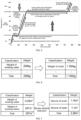
- FIG. 5 is a view illustrating movement of energy (cal) according to a change in state of water, i.e., a view illustrating movement of energy required for changing a state to steam by melting ice to raise a temperature and boiling the water to a temperature of more than 100°C.
- latent heat of fusion (calorie required to melt 1g of ice) is 80 cal
- latent heat of vaporization (calorie required to boil 1g of water) is 540 cal
- specific heat calorie required to raise 1g of water is 1 cal. In this case, if it needs to avoid the boiling of water to a temperature of more than 100°C, the heat required to raise 1g of ice to 99 is about 180 cal.
- the present disclosure does not cool the compressed air using pure cooling water, but cool the compressed air using slush in which ice and water are mixed.
- a weight (x) of the slush required when the slush in which ice and water are mixed is used at the latent heat 176,900 kcal that is required for cooling the compressed air using the pure cooling water calculated above is as follows.
- the total weight of the slush in which ice and water are mixed is 1,160 kg
- the total volume of the slush in which the ice and water are mixed is 1.16 m 3 .
- the water weight is 290 kg
- the total weight of the slush in which the ice and water are mixed is 1,160 kg. That is, fourth times difference occurs in weight of the slush in which ice and water are mixed.
- the sum of the existing water volume of 0.29 m 3 and the steam volume of 207 m 3 is generally 207 m 3 .
- the sum of the volume of 1.16 m 3 of the slush in which ice and water are mixed and the water volume 1.1 m 3 is 2.26 m 3 .
- the volume (207 m 3 ) of steam is very large, and thus, since the volume of the steam tank is larger than that of the capsule vehicle, it is impossible to be practically applied as the compressed air cooling system using cooling water.
- the slush in which ice and water are mixed is used, since a steam container having a large volume is not required, and the steam tank is removed by utilizing the slush, the overall volume reduction is 92 times, which makes it practical for the hypertube transport system.
- the present disclosure uses a mixture instead of the pure water in order to further lower the freezing point when preparing the slush.
- propanediol (C 3 H 8 O 2 ) and ethylene glycol (C 2 H 6 O 2 ), which are well mixed with water are used as a component of the mixture.
- EG is ethylene glycol (C 2 H 6 O 2 )
- PG is propylene glycol (C 3 H 8 O 2 )
- PDO propanediol (C 3 H 8 O 2 ) .
- the mixture consists of 90% to 70% by weight of propanediol (C 3 H 8 O 2 ) and 10% to 30% by weight of ethylene glycol (C 2 H 6 O 2 ) .
- the slush in which ice and water are mixed, and the mixture of propanediol (C 3 H 8 O 2 ) and ethylene glycol (C 2 H 6 O 2 ) may be preferably mixed at a weight ratio of 1 : 9.
- a mixing weight ratio of water in this case, water is slush in which ice and water are mixed
- propanediol (C 3 H 8 O 2 ) and ethylene glycol (C 2 H 6 O 2 ) are mixed at the above-described weight ratio
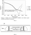
- a freezing point is lowered to "-100°C" or less, to further reduce the volume of the cooling system as a whole.
- the refrigerant in which water is mixed with the mixture of propanediol (C 3 H 8 O 2 ) and ethylene glycol (C 2 H 6 O 2 ) is boiled at 200°C or more, and there is no need to worry about gasification.
- FIG. 9 is a view illustrating an electromagnet disposed in a train vehicle running in a vacuum tube and devices for controlling the electromagnet according to an embodiment of the present disclosure.
- a tube running train vehicle 200b runs in a tube infrastructure 10b, which is maintained in a vacuum state.
- the tube infrastructure 10b has a tunnel shape, and the whole or a portion of the tube is made of a conductor for the running of the maglev train.
- the tube infrastructure 10b is provided by connecting tube modules, each of which has a predetermined unit length, in series.
- each of the tube modules is made of a conductor, or a portion of the tube module extending in a running direction of the train is made of a conductor.
- the tube running train vehicle 200b runs in the tube that is entirely made of a conductor or periodically runs in the tube in a shape that passes through the conductor portion.
- the tube running train vehicle 200b includes a first electromagnet 210b disposed on a front head of a vehicle body extending to have a predetermined length, a second electromagnet 220b disposed on a rear tail of the vehicle body, and a power supply 230b supplying power to the first electromagnet 210b and the second electromagnet 220b. Also, the tube running train vehicle 200b includes a running controller 240b that manages various control signals related to driving of the tube running train vehicle 200b, and in particular, generating a braking signal of the vehicle to transmit the braking signal to the power supply 230b.
- Each of the first electromagnet 210b and the second electromagnet 220b may be a coil wound along a direction perpendicular to the running direction of the vehicle.
- a magnetic field in a direction parallel to the running direction of the train is formed.
- a magnetic field proceeding in the running direction of the vehicle may be formed by the first electromagnet 210b
- a magnetic field proceeding in an opposite direction to the running direction of the vehicle may be formed by the second electromagnet 220b.
- the magnetic field is formed so that the front heat of the tube running train vehicle 200b has an N polarity, and the rear tail of the tube running train vehicle 200b has an S polarity.
- FIG. 10 is an exemplary view illustrating a shape of the electromagnet disposed in the train vehicle running in the vacuum tube 200b according to an embodiment of the present disclosure.
- first electromagnet 210b and the second electromagnet 220b which are respectively disposed at the front head and the rear tail.
- one or more additional third electromagnets 250b may exist between the first electromagnet 210b and the second electromagnet 220b, but the number of third electromagnets 250b is not limited to the present disclosure.
- the third electromagnet 250b may be a coil wound in the direction perpendicular to the running direction of the vehicle.
- a magnetic field in a direction parallel to the running direction of the vehicle is formed.
- the magnetic field in which the N polarity is formed on a front surface of the third electromagnet 250b, the S polarity is formed on a rear surface of the third electromagnet 250b may be formed.
- the electromagnet may be manufactured in various forms depending on the location or the shape of the vehicle. Basically, the electromagnet may be provided as a multiple coil type 520b constituted by one coil type 510b and a plurality of conductive coils 410b. The electromagnet of the one coil type 510b or the electromagnet of the multiple coil type 520b may be selectively disposed on the front head or the rear tail of the vehicle. However, the form and arrangement of the electromagnet are not limited to the present disclosure.
- FIG. 11 is an exemplary view for explaining a braking principle of the train vehicle 200b according to an embodiment of the present disclosure.
- FIGS. 11 and 12 illustrate Faraday's law and Lenz's law, which are physics laws used to have braking force in the tube running train vehicle 200b according to an embodiment of the present disclosure.
- FIG. 11 illustrates an example of Faraday's law in which induction electromotive force is generated when the permanent magnet 420b passes through the coil 430b, and a current value flowing through the coil 430b is determined by an impedance value of the coil 430b when the permanent magnet 420b moves at a speed or has a magnetic field that is changed as time elapses.
- FIG. 12 illustrates a case in which the permanent magnet 420b passes through the inside of the coil 430b, i.e., an example of Lenz's law in which different polarities are generated between the rear tail of the permanent magnet 420b and the coil 430b if the same polarity is generated between the front head of the permanent magnet 420b and the coil 430b, which are adjacent to each other, and the permanent magnet 420b is away from the coil 430b by passing through the coil 430b.
- FIGS. 13 and 14 illustrate the braking principle of the vehicle using Faraday's law and Lenz's law, which are the physical laws described above, according to an embodiment of the present disclosure.
- the magnetic field is formed so that the front head of the vehicle has the N polarity in the running direction of the vehicle through the first electromagnet 210b, and the rear tail has the S polarity in a direction opposite to the direction in which the train runs through the second electromagnet 220b.
- the magnetic field is formed also so that a front surface has an N polarity in the same direction as the running direction of the vehicle, and a rear surface has an S polarity in a direction opposite to the direction in which the vehicle runs with respect to the third electromagnet.
- the vehicle has the same characteristics as one permanent magnet 420b.
- the same N polarity may be formed between the front head of the vehicle and the specific point 440b of the tube according to Lenz's law to generate repulsive force, and different polarities may be formed between the rear tail of the vehicle, which passes through the specific point 440 of the tube, and the specific point 440 to generate attractive force, thereby generating braking force.
- the specific points 440b may act as the tube having the characteristics of a conductor. This may be represented by the conductor tube 20b of FIG. 14 .
- the actual vehicle moves inside the conductor tube 20b formed by the above-described principle, and the braking force of the vehicle is determined in proportion to strength of the magnetic field generated in the vehicle and strength of the magnetic field induced to the conductor tube 20b.
- the magnetic field induced in the conductive tube 20b is determined by three parameters such as a running speed of the vehicle, strength of the magnetic field from the conductor tube (20b) to the running direction, and a material and shape of the conductive tube 20b.
- the parameters that may be actually controlled may be the strength of the magnetic field from the conductive tube 20b to the running direction.
- the parameters may be changed by adjusting the current supplied to the electromagnet through the power supply 230b.
- FIG. 16 is a perspective view of the maglev superconducting electromagnet provided with the superconducting switch according to an embodiment of the present invention.
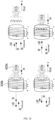
- FIGS. 17a and 17b are equivalent circuit diagrams illustrating a state in which a superconducting coil of the superconducting electromagnet of FIG. 16 operates in a permanent current mode and a charging mode.
- the superconducting switch according to this embodiment is provided in the superconducting electromagnet illustrated in FIG. 16 .
- a structure of the superconducting electromagnet and its equivalent circuit will be described with reference to FIGS. 16, 17a , and 17b .
- the superconducting electromagnet 10c is an electromagnet manufactured by winding a wire-shaped superconductor in a coil shape by using a characteristic in which electrical resistance of the superconductor is 0 [ ⁇ ].
- electrical resistance of the superconductor is 0 [ ⁇ ].
- the superconducting electromagnet 10c includes a superconducting coil 11c capable of generating a magnetic field, a cooling bath 20c for protecting the superconducting coil and maintaining a cryogenic temperature of below 190 degrees Celsius, a thermal shield 30c for blocking intrusion of radiant heat from the outside, and a current terminal 40c for supplying current to the superconducting coil.
- the superconducting electromagnet 10c is constituted by a plurality of superconducting coils 11c.
- the superconducting coil 11c is provided in a cryogenic container and is cooled by liquid nitrogen at a temperature of 77K inside the cryogenic container.
- the superconducting coils 11c are connected in series, and both ends of each of the superconducting coils 11c are electrically connected to the current terminal 40c. Therefore, a circuit in which an external power source (DC current source) is connected to the current terminal 40c, and a flow of the current is controlled using a switching device that is adequately designed, thereby controlling excitation of the superconducting coil 11c for the magnetic levitation.
- DC current source DC current source
- the switching device 100c (hereinafter, referred to as a ⁇ superconducting switch') is disposed inside the superconducting electromagnet 10c.
- the superconducting switch 100c maintains a superconducting state when the superconducting switch 100c is disposed in the cryogenic container to short-circuit both ends of the superconducting coil 11c, as illustrated in FIG. 17a , thereby making the superconducting coil 11c having a close loop shape.
- electrical resistance of the coil 11c is zero, the current flows continuously to the superconducting coil 11c without supply of external power, and an operation method of the superconducting coil 11c is referred to a permanent current mode.
- the superconducting switch 100c has to be in an ON state.
- the superconducting switch has to be maintained below a threshold temperature, and thus, the superconducting switch is maintained in a superconducting state so that the electrical resistance is maintained to 0 [ ⁇ ].
- the superconducting switch 100c may be a component of the superconducting electromagnet 10c.
- the superconducting switch 100c may serve as a switching through which a charging mode for performing charging on the superconducting coil 11c and a permanent current mode in which continuous current flows are selectively performed.
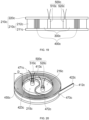
- FIG. 18 is a perspective view illustrating the superconducting switch to which the maglev superconducting electromagnet of FIG. 16 is applied
- FIG. 19 is a cross-sectional view of the superconducting switch, taken along line I-I' of FIG. 18
- FIG. 20 is an internal configuration diagram of the superconducting switch of FIG. 18
- FIG. 21 is a schematic view illustrating a state in which the superconducting wire of the superconducting switch of FIG. 18 is wound.
- the superconducting switch 100c includes a case 200c, a bobbin 300c, a superconducting wire 400c, and a heater 500c.
- the case 200c includes a main body 210c of which an upper portion is opened to accommodate the bobbin 300c, the superconducting wire 400c, and the heater 500c and a cover part 220c that covers the opened upper portion of the main body 210c.
- the main body 210c has a bottom part 211c having a circular plate shape, and a sidewall part 212c having a predetermined height is formed on a circumference of the circular plate shape of the bottom part 211c so that only the upper portion is opened.
- the cover part 220c covers only a portion of the opened upper portion.
- a central portion 213c of the main body 210c is maintained in an open state to cover only a predetermined distance from the circumference
- the cover part 220c covers only the superconducting wire 400c accommodated in the main body 210c. Accordingly, an area on which the superconducting wire 400c is wound is also formed from the circumference of the main body 210c by only a certain distance.
- the superconducting wire 400c may be in non-contact with an external cooling medium (liquid helium) outside the case 200c.
- the case 200c may be made of a heat insulating material, for example, a fiber reinforced plastic (FRP) material.
- FRP fiber reinforced plastic
- the bobbin 300c provides a place for winding the superconducting wire 400c, that is, serves as a support on which the superconducting wire 400c is wound.
- the bobbin 300c is installed in a hollow cylindrical shape in the case 200c, that is, in the central portion 213c of the main body 210c, and thus a central space 214c is formed in the central portion 214c.
- the material may be made of a conductive material so as to transfer heat generated from the heater 500c to the superconducting wire 400c.
- a diameter of the bobbin 300c is less than that of a bottom surface of the main body 210c.
- the bobbin 300c is spaced a predetermined distance D from the sidewall part 212c of the main body 210c, and the superconducting wire 400c is wound in a winding space 450c having the predetermined distance D.
- the superconducting wire 400c is supported by the bobbin 300c as described above and wound up to the sidewall part 212c of the main body 210c along an outer surface of the bobbin 300c.
- the superconducting wire 400c includes first and second wire units 410c and 420c stacked on each other as illustrated in FIG. 21 .
- the first and second wire units 410c and 420c are substantially one extending wire, and when the two ends 411c and 421c of one extending wire are positioned to face each other, as illustrated in FIG. 21 . As described above, the pair of first and second wire units 410c and 420c overlapping each other extend to be positioned adjacent to each other.
- the first and second wire units 410c and 420c are the extending one wire, the first and second wire units 410c and 420c have the same thickness and width and substantially the same shape. Thus, the first and second wire units 410c and 420c are stacked on each other and wound in the winding space 450c.
- ends 431c at which the first and second wire units 410c and 420c are connected to each other may be formed to extend in a rounded shape to prevent the damage and short circuit from occurring. That is, the first and second wire units 410c and 420c may be partially spaced apart from each other by forming the bent shape around the ends 431c connected to each other.
- the first and second wire units 410c and 420c extend in the rounded shape to reach both ends 411c and 421c of each of the first and second wire units 410c and 420c so as to be adjacent to overlap each other.
- ends 431c, which are connected to each other, of the first and second wire units 410c and 420c are formed to extend in the rounded shape, ends 413c and 423c of the first and second wire units extending from the ends 431c may be spaced apart from each other.
- the one end 413c of the first wire unit 410c is disposed in the central space 214c of the bobbin 300c, and the one end 423c of the second wire unit 420c is disposed in the winding space 450c formed between the bobbin 300c and the circumference of the case 200c and thus is wound along the outer surface of the bobbin 300c.
- the bobbin 300c has a first through-hole 471c through which the one end 431c to which the first and second wire units 410c and 420c are connected to each other and a second through-hole 472c configured so that the end 413c of the first wire unit 410a extends to overlap the second wire unit 420c so as to be wound around the outer surface of the bobbin 300c.
- the one end 413c of the first wire unit 410c may be formed in the center of the bobbin 300c as illustrated in the drawings.
- the heater 500c includes a first heater 510c and a second heater 520c
- the first and second heaters 510c and 520c may be symmetrically formed with respect to the one end 413c.
- the first heater 510c is disposed in a first space 215c of the central space 214c
- the second heater 520c is disposed in a second space 216c of the central space 214c.
- the first and second heaters 510c and 520c do not deviate from either of the central spaces 214c of the bobbin 300c and are respectively disposed in the first and second spaces 215c and 216c with respect to the center of the bobbin 300c so as to be symmetrical to each other. As a result, generated heat may be uniformly transferred to the first and second wire units 410c and 420c.
- FIG. 20 illustrates that the heater 500c includes two first and second heaters 510c and 520c
- the number of heaters may be variously changed in design depending on an amount of heat transferred to the first and second wire units 410c and 420c.
- the first and second wire units 410c and 420c may extend relatively lengthily, and thus, it may be possible to implement the superconducting wire 400c extending relatively lengthily in the space of the volume, thereby manufacturing the superconducting switch having the large resistance (Rpcs).
- each of the first and second wire units 410c and 420c may be covered with an insulator.
- the first and second wire units 410c and 420c may be insulated using an insulating tape, for example, a cotton-rubber tape.
- the cotton-rubber tape is generally used for electrical insulation and has a slight viscosity.
- the first and second wire units 410c and 420c may be insulated from each other and also be insulated from the bobbin 300c.
- the resistance between the first and second wire units 410c and 420c may decrease due to the electrical connection between the first and second wire units 410c and 420c, and the switching function of the superconducting wire 400c by the resistance may be faithfully performed.
- both ends 412c and 422c of the first and second wire units 410c and 420c extend through a third through-hole 473c formed in the bobbin 300c to extend outward.
- it may be connected to the superconducting magnet 10c disposed outside to perform the switching function.
- the function of the superconducting switch 100c for the permanent current mode operation of the maglev superconducting electromagnet according to the present embodiment configured as described above is as described with reference to FIGS. 17a and 17b .
- the current terminal 40c when it is necessary to apply current from an external power source to the superconducting magnet, the current terminal 40c is connected.
- the current terminal 40c When the current terminal 40c is connected, a closed circuit is formed between the external power supply and the superconducting magnet so that the current flows.
- the heater 500c when the current is applied from the external power source, the heater 500c also operates, and thus, heat is generated from the heater 500c.
- the heat generated by the heater 500c is transferred to the bobbin 300c and is transferred from the bobbin 300c to the superconducting wire 400c.
- the power supplied from the external power source is charged in the superconducting coil 11c.
- the current supply is stopped because no closed circuit is formed between the external power supply and the superconducting magnet.
- the heat from the heater 500c is no longer generated, and thus, the superconducting wire 400c is cooled again.
- the superconducting wire 400c is cooled below the so-called critical temperature, the superconducting wire 400c is changed from phase conduction to superconductivity to maintain the cryogenic state.
- the superconducting switch 100c is cooled below a predetermined threshold temperature to exhibit superconductivity, thereby forming the closed circuit with the superconducting magnet. Since the superconducting wire 400c has no resistance component, the superconducting wire 400c may constitutes a permanent current mode in which current continuously flows even though no more current is supplied from the outside.
- the first and second wire units since the first and second wire units are stacked and wound several times in the winding space, the first and second wire units may extend relatively lengthily, and thus, it may be possible to implement the superconducting wire extending relatively lengthily in the space of the volume, thereby manufacturing the superconducting switch having the large resistance (Rpcs).
- the discharge rate may increase, which is advantageous to apply to the large-capacity maglev superconducting electromagnet.
- the heater and the bobbin are installed inside the case and are covered by the cover part, the heater and the bobbin may do not directly contact the external liquid nitrogen to prevent the bubble phenomenon of the liquid nitrogen from occurring by the superconducting switch, thereby improving the driving stability.
- the first and second wire units may be electrically insulated from each other even if overlapping each other and may be insulated from the bobbin.
- the resistance between the first and second wire units may decrease due to the electrical connection between the first and second wire units, and the switching function of the superconducting wire by the resistance may be faithfully performed.
- first and second wire units are formed so that each of both the ends of the first and second wire units, which are connected to each other, extend in the rounded shape, when the first and second wire units extend to contact each other, the damage or short circuit of the first and second wire units due to the bending at the connection portion therebetween may be prevented.
- FIG. 22 is an explanatory diagram illustrating the hypertube transport system to which the present disclosure is applied.
- the hypertube transport system generally runs at a high speed of 1,200 km/h or more in a maglev and propelled manner inside a closed partial vacuum tube that is isolated from an external atmospheric pressure.
- An electromagnetic rail is installed inside the tube so that the vehicle runs in the maglev and propulsion manner, and the superconducting electromagnet or a magnetic body that performs a similar function is installed at the vehicle side. Furthermore, a wheel is installed as an auxiliary running unit on a side of the vehicle for driving the wheel in an atmospheric pressure section and a low speed section.
- the hypertube transport system according to the present disclosure is disclosed in Korea Patent Publication No. 2010-0090406 (Title of Disclosure: PROPULSION AND GUIDANCE TYPE TUBE TRANSPORTATION SYSTEM), Korean Patent Registration No. 1015170 (Title of Disclosure: TUBE TYPE MAGLEV TRAIN), Korean Patent Registration No. 1130807 (Title of Disclosure: VACUUM SECTIONAL MANAGEMENT SYSTEM AND VACUUM BLOCKING SCREEN DEVICE FOR THE TUBE RAILWAY), and Korean Patent Registration No. 1130811 (Title of Disclosure: DEVICE AND CONTRAL METHOD OF INTERFACE STATION BETWEEN TUBE RAILWAY AND ATMOSPHERE RAILWAY) by the applicant.
- the hypertube transport system has a special vehicle running environment compared to an existing vehicle, and this special vehicle running environment may include a case in which the vehicle runs in the tube in the partial vacuum state sealed from an external atmospheric pressure, a case in which the vehicle runs by the electromagnetic force interaction between the electromagnetic rail inside the tube and the electromagnet on the vehicle side, a case in which air resistance is generated by high-speed running of the vehicle inside the partial vacuum tube, and a case in which the vehicle constituted by a vehicle body and a bogie is used.
- an embodiment of the present invention proposes a vehicle driving stabilization technique, i.e., a technique in which an elastic plate, a passive suspension, an active suspension, an electromagnetic force damper, and an aerodynamic adjustment vane are selectively installed in a vehicle running in a tube that is in a partial vacuum state to reduce an impact caused by various disturbances such as vibration, electromagnetic force, air resistance, and the like, which are caused by special vehicle driving environments, thereby improving driving stability of the vehicle.
- the elastic plate, the passive suspension, the active suspension, the electromagnetic force damper, and the aerodynamic adjustment vane of the vehicle driving stabilization apparatus will be referred to collectively as a disturbance impact attenuator.
- the elastic plate, the passive suspension, and the active suspension of the vehicle driving stabilization apparatus according to the present disclosure will be described with reference to FIGS. 23a and 23b .
- the electromagnetic force damper will be described with reference to FIG. 24
- the aerodynamic adjustment vane of the vehicle driving stabilization apparatus according to the present disclosure will be described with reference to FIG. 25 .
- FIGS. 23a and 23b are configuration diagrams of the vehicle driving stabilization apparatus according to a first example of the present invention.
- the first hypertube transport system includes a vehicle constituted by a tube 110d, a vehicle body 100d, and a bogie 101d in the partial vacuum state sealed from the external atmospheric pressure and a wheel 103d installed at a side of the bogie 101d to serve as an auxiliary running unit in the atmospheric pressure section.
- the vehicle runs in the tube in the maglev and propulsion manner by the electromagnetic force interaction between the electromagnetic rail 106d provided at an inner side of the tube 110d and the superconducting electromagnet 107d or other magnetic material provided on the side of the bogie 101d.
- Reference numeral 102d denotes a guiding wheel
- reference numeral 105d denotes a railway.
- the superconducting electromagnet is installed on the vehicle side in the case of the maglev and propulsion of the vehicle as an example.
- any magnetic method such as a phase conduction suction method other than the superconducting electromagnetic method, and it is preferable to understand that the superconducting electromagnet 107d described below as an example collectively refers to a magnet.
- the inner sidewall of the tube 110d in the hypertube transport system are provided with components for the maglev and propulsion and the running and braking of the vehicle by the wheels.
- the vehicle body 100d provides a passenger boarding space, and most of the components related to vehicle running and braking are installed in the bogie 101d.
- the passive suspension 113d, the active suspension 112d, the elastic plate 104d and the electromagnetic force damper of the vehicle driving stabilization apparatus may be preferably installed at the side of the bogie 101d to attenuate transmission of the impact due to various disturbances to the vehicle body 100d of the passenger boarding space.
- the elastic plate 104d of the vehicle driving stabilization apparatus proposed in the present disclosure is installed on the side of the vehicle bogie 101d, and preferably the vehicle bogie 101d adjacent to the vehicle body 100d in an inward direction from the outside of the vehicle. In FIGS. 23a and 23b , it is seen that the elastic plate 104d is installed at a rear end of the superconducting electromagnet 107d or other magnetic material installed in the vehicle bogie 101d.
- the elastic plate 104d is installed at the rear end of the superconducting electromagnet 107d or other magnetic material on the side of the vehicle bogie 101d to attenuate the impacts, which are applied by various disturbances such as physical deformation of the tube such as tube protrusion, tube drooping, tube joint step, and the like, an installation alignment error of the electromagnetic rail inside the tube, non-uniform electromagnetic force between the tube side electromagnetic rail and the vehicle side electromagnet, centrifugal force in the curved running section, air resistance or irregular air flow inside the tube, and the like, at the side of the bogie 101d, thereby preventing the impacts from being transmitted to the vehicle body 100d.
- various disturbances such as physical deformation of the tube such as tube protrusion, tube drooping, tube joint step, and the like, an installation alignment error of the electromagnetic rail inside the tube, non-uniform electromagnetic force between the tube side electromagnetic rail and the vehicle side electromagnet, centrifugal force in the curved running section, air resistance or irregular air flow
- the elastic plate 104d may be made of, for example, a rubber member, and any member having a certain amount of rigidity and having impact attenuation performance such as vibration may be used.
- the passive suspension 113d of the vehicle driving stabilization apparatus proposed by the present disclosure is provided at a portion at which the vehicle bogie 101d and the vehicle body 100d contact each other.
- the passive suspension 113d may be constituted by a spring 114d and a damping member 115d, and the spring 114d may buffer the impact applied by various disturbances to the vehicle body 100d from the vehicle bogie 101d to prevent the impact from being transmitted and also allow the damping member 115d to absorb and suppress the impact such as vibration applied by various disturbances.
- the active suspension 112d of the vehicle driving stabilization apparatus proposed by the present disclosure includes an actuator for driving a suspension component such as an impact absorber, a spring, and a cylinder, a controller for controlling an operation of the actuator, and a sensor for detecting a vehicle driving state.
- a suspension component such as an impact absorber, a spring, and a cylinder
- the actuator may be used without limitation, such as hydraulic, pneumatic, electromagnetic, electro-liquid manners, and the like.
- Suspension components of the active suspension 112d are installed at an upper side of the vehicle bogie 101d supporting the vehicle body 100d to control the behavior of the vehicle body 100d in a propulsion direction (X axis), a horizontal direction (Y axis), and a vertical direction (Z axis) according to the driving of the actuator, thereby maintaining a vehicle posture corresponding to the optimum riding comfort and attenuating the impacts such as the vibrations applied by various disturbances.
- the sensor of the active suspension 112d detects a vertical displacement, a horizontal displacement, a speed, and an acceleration by the vehicle body 100d and the vehicle bogie 101d to transmit the detected values of the vehicle driving state to the controller of the active suspension 112d.
- the controller of the active suspension unit 112d determines the vehicle driving state by using the vertical displacement, the horizontal displacement, the speed, and the acceleration transmitted from the sensor and controls the actuator driving according to the determined vehicle driving state, thereby adjusting the behavior of the vehicle body 100d so that the suspension components operate in the propulsion direction (X axis), the horizontal direction (Y axis) and the vertical direction (Z axis).
- FIG. 24 is a configuration diagrams of a vehicle driving stabilization apparatus according to a second example of the present invention.
- An electromagnetic force damper 108d of the vehicle travel stabilization apparatus proposed in the present disclosure is installed on a side of the vehicle bogie 101d, preferably installed at a predetermined portion of the vehicle bogie 101d that is adjacent to the electromagnetic rail 106d that is installed on the inner sidewall of the tube 110d outward from the inside of the vehicle.
- the electromagnetic force damper 108d is installed at a front end of the superconducting electromagnet 107d or other magnetic body installed in the vehicle bogie 101d so as to be installed on a side surface of the vehicle bogie 101d to face the electromagnetic rail 106d installed on the inner sidewall of the tube 110d.
- the electromagnetic force damper 108d attenuates the electromagnetic vibration due to the disturbance generated between the vehicle-side superconducting electromagnet 107d and the tube-side electromagnetic rail 106d, for example, the installation alignment error of the electromagnetic rail inside the tube, the non-uniform electromagnetic force between the tube side electromagnetic rail and the vehicle side electromagnet, and the like.
- the electromagnetic force damper 108d may be made of a member capable of exhibiting electromagnetic force damping performance through a member having a conductive plate or a special coil embedded therein, for example, may be provided as an aluminum plate.
- FIG. 25 is a configuration diagrams of a vehicle driving stabilization apparatus according to a third example of the present disclosure.
- An aerodynamic adjustment vane 109d of the vehicle driving stabilization apparatus proposed in the present disclosure is installed on an outer portion of the vehicle, preferably, a portion of the vehicle, which is exposed to the inside of the tube that is in the partial vacuum state.
- the aerodynamic adjustment vane 109d provided on the outer portion of the vehicle attenuate the air resistance or the irregular air fluctuation caused by the air flow passing through a gap between the inner wall of the tube and the outside of the vehicle, thereby stably maintaining the vehicle posture. That is, artificial force is generated to the vehicle by using a flow of air generated when the vehicle runs to catch the shaking of the vehicle.
- FIG. 25 illustrates that the aerodynamic adjustment vane 109d is provided on the upper side of the vehicle
- the aerodynamic adjustment vane 109d may be installed on any portion such as the side surface of the vehicle to attenuate the air resistance caused by the air flow passing through the gap between the inner wall of the tube and the outside of the vehicle, thereby stably maintaining the vehicle posture.
- the aerodynamic adjustment vane 109d is installed in the vehicle in a fixed form to attenuate the air resistance due to the air flow inside the tube when the vehicle runs or is installed in the vehicle in a movable form that moves according to the air flow inside the tube when the vehicle runs.
- FIG. 26a is an explanatory diagram illustrating the hypertube transport system to which the present disclosure is applied.
- the vehicle runs in the tube that is the partial vacuum state at a high speed of 1,200 km/h or more in the maglev and propulsion manner.
- the compressor is provided on the front head-side of the vehicle to compress the air flowing into the front head of the vehicle, thereby discharging the compressed air backward.
- a fan of the compressor is shown on the front head-side of the vehicle in FIG. 26a .
- the vehicle running at the high speed inside the tube is limited by a maximum speed through the Kantrowitz limit.
- a flow rate between the tube and the vehicle is almost zero to cause a choking phenomenon.
- an axial compressor is provided on the front head of the vehicle to avoid the choking phenomenon.
- the hypertube transport system according to the present disclosure is disclosed in Korea Patent Publication No. 2010-0090406 (Title of Disclosure: PROPULSION AND GUIDANCE TYPE TUBE TRANSPORTATION SYSTEM), Korean Patent Registration No. 1015170 (Title of Disclosure: TUBE TYPE MAGLEV TRAIN), Korean Patent Registration No. 1130807 (Title of Disclosure: VACUUM SECTIONAL MANAGEMENT SYSTEM AND VACUUM BLOCKING SCREEN DEVICE FOR THE TUBE RAILWAY), and Korean Patent Registration No. 1130811 (Title of Disclosure: DEVICE AND CONTRAL METHOD OF INTERFACE STATION BETWEEN TUBE RAILWAY AND ATMOSPHERE RAILWAY) by the applicant.
- the basic technical configuration of the hypertube transport system for the purpose of technical understanding of the present disclosure is as follows, it will be clear that the technical gist of the present disclosure is not limited by the basic technical configuration.
- the hypertube transport system includes a tube that is isolated from the outside to maintain the inside at a low pressure, that is, a vacuum state, a vehicle running inside the tube in the vacuum state, a liner synchronous motor (LSM) constituted by a stator provided at a track side of the tube and a rotor provided in the vehicle to correspond to the tube-side stator to generate propulsion force in a longitudinal direction of the tube, a levitation guide unit that levitates the vehicle by the magnetic force and places the vehicle on a concentric axis within the tube, and a power supply device installed on an upper portion of an inner circumferential surface of the tube and an outer circumferential surface of the vehicle corresponding to the upper portion to supply power to the vehicle.
- LSM liner synchronous motor
- FIG. 26b is a configuration diagram illustrating a vehicle braking apparatus of a hypertube transport system according to a first example of the present invention
- FIGS. 27a to 27c are perspective views of a compressor opening/closing vane of FIG. 26b
- FIG. 28 is a graph illustrating vehicle braking performance when the compressor opening/closing vane of FIG. 26b is used
- FIG. 29 is a perspective view of a flow gap blocking vane of FIG. 26b
- FIG. 30 is an explanatory view illustrating an operation of the flow gap blocking vane of FIG. 26b
- FIGS. 31a and 31b are explanatory view illustrating an operation control algorithm of a vehicle braking apparatus according to a first example of the present invention
- FIGS. 33a, 33b , 34a, and 34b are configuration diagrams illustrating a vehicle braking apparatus of a hypertube transport system according to a second example of the present invention
- FIG. 35 is an explanatory view illustrating a water supply device for a moisture expansion material according to the second example of the present invention
- FIGS. 36a to 36e are explanatory views illustrating the moisture expansion material according to the second example of the present invention.
- the present disclosure proposes a vehicle braking apparatus of a hypertube transport system, that is, a vehicle front-side air flow blocking technique that is optimized for a partial vacuum tube environment.
- a compressor opening/closing vane, a flow gap blocking vane, and a moisture expansion material are selectively installed at a front head-side of a vehicle running in a tube that is in a partial vacuum state to block a flow of air passing through the front head-side of the vehicle or block a flow of air passing through a gap between the vehicle and the tube, thereby braking the vehicle.
- the compressor opening/closing vane, the flow gap blocking vane, and the moisture expansion material may be referred to as a vehicle side air flow blocking part.
- the present disclosure proposes an intelligent control algorithm (so-called : KLB & VC (Kantrowitz Limit Braking & Velocity Control)) in performing of vehicle braking through the compressor opening/closing vane and the flow gap blocking vane installed on a front head of the vehicle.
- the vehicle running at the high speed inside the tube is limited by a maximum speed through the Kantrowitz limit.
- the maximum speed approaches a speed of sound, a flow rate between the tube and the vehicle is almost zero to cause a choking phenomenon.
- the Cantrowitz limit is applied to the vehicle running in the tube, the maximum speed of the vehicle is determined within the tube.
- the speed of the vehicle to which the Kantroywitz limit is applied is determined by a cross-sectional ratio of the vehicle and the tube at a speed slightly lower than the sound speed, i.e., a blockage ratio (BR).
- BR blockage ratio
- the present disclosure is to propose a vehicle deceleration and braking technique that are implemented by the air flow blocking technique applying the Kantrowitz Limit.
- FIG. 26a is an explanatory diagram illustrating the hypertube transport system to which the present disclosure is applied.
- a compressor fan 21e is provided on the front head-side of the vehicle 20e that runs in the tube 10e in a partial vacuum state, and in particular, a compressor opening/closing vane 30e or/and a flow gap blocking vane 40e as vehicle braking devices based on an air flow blocking technique using the Kantrowitz Limit proposed in the present disclosure is/are provided at the front head-side of the vehicle.
- the compressor opening/closing vane 30e is preferably installed at a front end of the vehicle front head-side compressor fan 21e, and as illustrated in FIG. 26b , the compressor opening/closing vane 30e performs an operation so that the compressor opening/closing vane 30e is opened to allow air to be introduced into the vehicle front head-side compressor fan 21e while the vehicle runs as illustrated in FIG. 26b and is gradually closed to block the air flow into the vehicle front head-side compressor fan 21e during the vehicle deceleration and braking.
- a control of an operation of the compressor opening/closing vane 30e is performed by an intelligent control algorithm (so-called : KLB & VC (Kantrowitz Limit Braking & Velocity Control)) to be described later.
- KLB & VC Kerantrowitz Limit Braking & Velocity Control
- the operation of the compressor opening/closing vane 30e is performed by a driving device such as an actuator, a hydraulic motor, a pneumatic motor, and the like
- the flow gap blocking vane 40e is preferably installed in a circumferential direction of the vehicle 20e, and as illustrated in FIG. 26b , the flow gap blocking vane 40e is laid down in a longitudinal direction of the vehicle 20e.
- air passes through the gap between the tube 10e and the vehicle 20e, and the flow gap blocking vane 40e performs an operation to be gradually erected (unfolded) in a direction of the cross-sectional area of the vehicle 20e so that the air does not pass through the gap between the tube 10e and the vehicle 20e during the vehicle deceleration and braking.
- a control of an operation of the flow gap blocking vane 40e is performed by an intelligent control algorithm (so-called : KLB & VC (Kantrowitz Limit Braking & Velocity Control)) to be described later.
- KLB & VC Knowles Limit Braking & Velocity Control
- the operation of the flow gap blocking vane 40e is performed by a driving device such as an actuator, a hydraulic motor, a pneumatic motor, and the like.
- FIG. 26b illustrates an example in which the flow gap blocking vane 40e is provided on the vehicle front head-side.
- the present disclosure is not limited thereto, for example. it is sufficient if the flow gap blocking vane 40e is provided in the vehicle circumferential direction such as a front head-side, a middle side, and a rear tail side in the vehicle longitudinal direction.
- the flow gap blocking vane 40e is installed to be in close contact with the circumferential surface of the vehicle 20e while the vehicle runs, and in FIG. 26b , it may be easily understood by those skilled in the art to have a rather erect shape to show the flow gap blocking wing 40e.
- FIGS. 27a to 27c are perspective views of the compressor opening/closing vane of FIG. 26b .
- FIG. 27a is a front view of the compressor opening/closing vane 30e while the vehicle runs
- FIG. 27b is a side view of the compressor opening/closing vane 30e while the vehicle runs so as to show a state in which the compressor opening/closing vane 30e is opened.
- An open state of the compressor opening/closing vane 30e may be seen as a grill shape.
- FIG. 27c is a side view of the compressor opening/closing vane 30e when the vehicle is decelerated and braked so as to show that the compressor opening/closing vane 30e are closed.
- the vehicle 20e running in the tube which is in the partial vacuum state, at a high speed of 1,200 km/h may be decelerated to a speed of 700 km/h by the Kantrowitz Limit during deceleration and braking of the vehicle.
- FIG. 28 is a graph illustrating the vehicle braking performance when the compressor opening/closing vane of FIG. 26b is used.
- FIG. 28 is illustrates performance in which the running speed of the vehicle 20e is decelerated by the Kantrowitz Limit phenomenon in the tube 10e that is in the partial vacuum state when the compressor opening/closing vane 30e of the present disclosure is closed.
- 'Vo' means a sound speed.
- FIG. 29 is a perspective view of the flow gap blocking vane of FIG. 26b .
- FIG. 29 is a front view of the flow gap blocking vane 40e when the vehicle is decelerated and braked so as to show a state in which the flow gap blocking vane 40e is fully erected (unfolded).
- the state in which the flow gap blocking vane 40e is fully erected (unfolded) may allow an end of the flow gap blocking vane 40e to be completely in contact with an inner surface of the tube 10e.
- a shape and size of the flow gap blocking vane 40e may be designed by a shape and size of the vehicle 20e in circumference and longitudinal directions, a shape and size of an inner surface of the tube 10e in circumference and longitudinal directions, and a gap between the vehicle 20e and the tube 10e.
- the vehicle 20e running in the tube that is in the partial vacuum state at a high speed of 1,200 km/h or more by the Kantrowitz Limit during the deceleration and braking using the compressor opening/closing vane 30e according to the present disclosure may be decelerated to a speed of 700 km/h or less. Then, when the air gap blocking vane 40e is fully erected (unfolded), for example, when the vane angle is 90°, air passing between the tube 10e and the vehicle 20e may be completely blocked to gradually decrease in speed and then stop.
- FIG. 30 is an explanatory view illustrating an operation of the flow gap blocking vane of FIG. 26b .
- the flow gap blocking vane 40e may be mounted on an outer surface of the vehicle 20e in the form of a hinge 41e to ascend and descend by the driving device 42e such as the actuator, the hydraulic motor, or the pneumatic motor, and the flow gap blocking vane 40e and the driving device 42e may be coupled to a sliding member 43e.
- the driving device 42e such as the actuator, the hydraulic motor, or the pneumatic motor
- the present disclosure proposes an intelligent control algorithm (so-called : KLB & VC (Kantrowitz Limit Braking & Velocity Control)) in performing of the vehicle braking through the compressor opening/closing vane 30e and the flow gap blocking vane 40e, which are proposed in the present disclosure.
- FIGS. 31a and 31b are explanatory view illustrating an operation control algorithm of the vehicle braking apparatus according to a first example of the present invention
- FIG. 32 is an explanatory view illustrating an angle of the compressor opening/closing vane and an angle of the flow gap blocking vane according to the first example of the present invention.
- V t is a time-varying speed of the vehicle
- V a is a speed of the vehicle averaged over time
- V T is a target speed of the vehicle
- a g is a vehicle deceleration
- X° is a closing angle of the compressor opening/closing vane
- Y° is an erected angle of the flow gap blocking vane.
- the vehicle front head-side compressor When the vehicle 20e runs in the tube 10e that is in the partial vacuum state, and then the vehicle needs to be decelerated and braked, the vehicle front head-side compressor is turned off. In the state in which the vehicle 20e runs normally, the vehicle front head-side compressor is driven, the compressor opening/closing vane 30e is open, and the flow gap blocking vane 40e is not in a standing state (unfolded).
- the running speed of the vehicle 20e is decelerated from 1,200 km/h to 800 km/h or less by the Kantrowitz Limit.
- the vehicle moves forward until the vehicle target speed is reached while gradually increasing in angle of the compressor opening/closing vane 30e, for example, by 1°.
- the angle X° of the compressor opening/closing vane 30e gradually increases, for example, by 1° to perform the closing operation of the compressor opening/closing vane 30e. That is, unless extreme vehicle braking conditions occur, it is preferable to suspend the operation of closing the compressor opening/closing vane 30e when the vehicle deceleration ag exceeds 0.5 g to cause the inconvenience to the passenger's mind and body due to the vehicle deceleration operation.
- the operation of closing the compressor opening/closing vane 30e is stopped until the deceleration of the vehicle reaches 0.5 g or less, and then the operation of closing the compressor opening/closing vane 30e starts again.
- This control may be performed until the compressor opening/closing vane 30e are completely closed.
- the vehicle speed for example, the time-averaged vehicle speed V a or the time-varying vehicle speed V t is measured to stop the operation of closing the compressor opening/closing vane 30e when the vehicle speed is equal to or less than the vehicle target speed VT.
- the vehicle speed for example, the time-averaged vehicle speed V a or the time-varying vehicle speed Vt, is measured so that, when the vehicle speed exceeds the vehicle target speed VT, the erected angle Y° of the flow gap blocking vane 40e gradually increases, for example, by 1° until the vehicle reaches the vehicle target speed.
- the angle Y° of the flow gap blocking vane 40e gradually increases, for example, by 1° to perform the operation of erecting the flow gap blocking vane 40e. That is, unless extreme vehicle braking conditions occur, it is preferable to suspend the operation of erecting the flow gap blocking vane 40e when the vehicle deceleration a g exceeds 0.5 g to cause the inconvenience to the passenger's mind and body due to the vehicle deceleration operation.
- the operation of erecting the flow gap blocking vane 40e is stopped until the deceleration of the vehicle reaches 0.5 g or less, and then the operation of erecting the flow gap blocking vane 40e starts again.
- This control may be performed until the angle Y° of the flow gap blocking vane 40e reaches 90°.
- the vehicle speed for example, the time-averaged vehicle speed V a or the time-varying vehicle speed V t is measured, and when the vehicle target speed V T is reached, the operation of erecting the flow gap blocking vane 40e is finished.
- FIGS. 33a, 33b , 34a, and 34b are configuration diagrams illustrating the vehicle braking apparatus of the hypertube transport system according to the second example of the present invention.
- a moisture expansion material 50e is installed in a circumferential direction of the front head-side of the vehicle 20e running in the tube that is in the partial vacuum state to block air passing through the gap between the tube 10e and the vehicle 20e, thereby performing the vehicle deceleration and braking.
- FIGS. 33a and 33b are side and front views of the hypertube transport system in which the moisture expansion material 50e is provided in the vehicle 20e in a normal running environment without the deceleration and braking.
- the air may pass through the vehicle front head-side compressor and the gap between the tube 10e and the vehicle 20e, and thus, it is seen that there is no effect on the vehicle deceleration and braking.
- FIGS. 34a and 34b are side and front views of the hypertube transport system in which the moisture expansion material 50e is provided in the vehicle 20e when the vehicle is decelerated and braked. It is seen that the vehicle deceleration and braking is performed by blocking the flow through the gas between the tube 10e and the vehicle 20e while the moisture expansion material 50e is expanded to perform the vehicle deceleration and braking.
- the compressor opening/closing vane 30e described in the first example of the present invention may be closed to block the flow to the vehicle front head-side compressor.
- the moisture expansion material 50e having a minimum volume is provided at the front head-side of the vehicle 20e. Then, moisture is supplied to this moisture expansion material 50e to be rapidly expanded, thereby completely sealing the gap between the tube 10e and the vehicle 20e without gaps.
- a shape and size of the moisture expansion material 50e may be designed by a shape and size of the vehicle 20e in circumference and longitudinal directions, a shape and size of an inner surface of the tube 10e in circumference and longitudinal directions, and a gap between the vehicle 20e and the tube 10e.
- FIGS. 33a and 34a illustrates an example in which the moisture expansion material 50e is installed at the vehicle front head-side.
- the present disclosure is not limited thereto, for example. it is sufficient if the moisture expansion material 50e is provided in the vehicle circumferential direction such as a front head-side, a middle side, and a rear tail side in the vehicle longitudinal direction.
- the moisture expansion material 50e is installed to be in close contact with a circumferential surface of the vehicle 20e while the vehicle runs, and in the drawing, it may be easily understood by those skilled in the art to have a predetermined thickness to show the moisture expansion material 50e.
- the vehicle 20e running in the tube that is in the partial vacuum state at a high speed of 1,200 km/h or more by the Kantrowitz Limit during the deceleration and braking using the compressor opening/closing vane 30e according to the first example of the present invention may be decelerated to a speed of 700 km/h or less. Then, when the moisture expansion material 50e is fully expanded, air passing between the tube 10e and the vehicle 20e may be completely blocked to gradually decrease in speed and then stop.
- FIG. 35 is an explanatory view illustrating a water supply device for the moisture expansion material according to the second example of the present invention.
- the water supply device for supplying water to the moisture expansion material 50e supplies water to the moisture expansion material 50e, which is a residue of the cooling device linked to the compressor of the vehicle 20e.
- the cooling device uses ice (slush) and water to cool the air, and then moisture remains as a residue.
- the moisture is supplied through by opening and closing a conduit connected to the moisture expansion material 50e from the cooling device during the vehicle deceleration and braking to expand the moisture expansion material 50e.
- the moisture expansion material 50e of an embodiment of the present invention may be implemented using a material of which a volume increases when moisture is supplied from the outside while being in a contracted state in a normal time.
- the moisture expansion material 50e may be made of a mixture of a calcium chloride-impregnated pore structure and superabsorbent polymer (SAP-iMPS-pCC : CaCl2-in-MesoPorous Silica grown on SuperAbsorbent Polymer), an MPS-pCC absorbent material, a zeolite absorbent material, a silica gel absorbent material, or the like.
- SAP-iMPS-pCC CaCl2-in-MesoPorous Silica grown on SuperAbsorbent Polymer
- MPS-pCC MPS-pCC absorbent material
- zeolite absorbent material a zeolite absorbent material
- silica gel absorbent material or the like.
- FIGS. 36a to 36e are explanatory views illustrating the moisture expansion material according to the second example of the present invention.
- the zeolite absorbent material or the silica gel absorbent material absorb moisture, it is known that its volume is expanded 300 times.
- the mixture of the calcium chloride-impregnated pore structure and the superabsorbent polymer absorbs moisture, it is known to be a novel chemical material of which a volume is expanded up to 1,000 times. Therefore, irrespective of a design of a gap between the tube 10e and the vehicle 20e, when the mixture of the calcium chloride-impregnated pore structure and the superabsorbent polymer material (SAP-iMPS-pCC) is used as the moisture expansion material 50e, the gap between the tube 10a and the vehicle 20e may be completely sealed without a gap.
- FIG. 36a illustrates a photomicrograph of the mixture of the calcium chloride-impregnated pore structure and the superabsorbent polymer (SAP-iMPS-pCC: CaCl2-in-MesoPorous Silica grown on SuperAbsorbent Polymer).
- the mixture of the calcium chloride-impregnated pore structure and the superabsorbent polymer (SAP-iMPS-pCC) has capability to absorb moisture up to six times rather than MPS-pCC that is an existing absorbent material.
- FIG. 36b illustrates moisture absorption capability of the mixture of the calcium chloride-impregnated pore structure and the superabsorbent polymer hybrid material (SAP-iMPS-pCC) under a temperature condition of 20°C.
- FIG. 36c illustrates moisture absorption capability of the mixture of the calcium chloride-impregnated pore structure and the superabsorbent polymer hybrid material (SAP-iMPS-pCC) under a temperature condition of 30°C.
- FIG. 36d illustrates moisture absorption capability of the mixture of the calcium chloride-impregnated pore structure and the superabsorbent polymer hybrid material (SAP-iMPS-pCC) under various relative pressures.
- FIG. 36e illustrates moisture absorption capability of the mixture of the calcium chloride-impregnated pore structure and the superabsorbent polymer hybrid material (SAP-iMPS-pCC) at various times.
- FIG. 37 is a schematic view of a maglev train including an energy harvester according to an embodiment of the present disclosure
- FIG. 38 is a view for explaining the energy harvester according to an embodiment of the present disclosure
- FIG. 39 is a view for explaining a first power generation module according to an embodiment of the present disclosure
- FIG. 40 is a view for explaining a second power generation module and a third power generation module according to an embodiment of the present disclosure
- FIG. 41 is a view for explaining an infrastructure system according to an embodiment of the present disclosure.
- maglev train 10f including an energy harvester according to an embodiment of the present disclosure (hereinafter, referred to as a 'maglev train 10f') will be described with reference to FIGS. 37 to 40 .
- the maglev train 10f includes a main body 111f of the train, a plurality of electromagnets 12f disposed on left and right surfaces of the main body 11f along a direction in which the maglev train 10f runs, and one or more energy harvesters 100f disposed on the main body 11f to generate power based on vibration of the main body 11f.
- the maglev train 10f is levitated to move by magnetic force on a track 30f.
- the track 30f is formed to extend in one direction, and a levitation coil 21f may be formed on the left and right surfaces to extend in a longitudinal direction of the track.
- the plurality of electromagnets 12f and the levitation coil 21f may be disposed to face each other, and thus levitation force and propulsion force may be generated by action between the electromagnet 12f and the levitation coil 21f.
- the present disclosure is not limited thereto, and the levitation coil 21f serves to levitate and guide the maglev train 10f, and a propulsion coil 29f is additionally disposed on the track 30f to provide the propulsion force to the maglev train.
- the above-described electromagnet 12f may be a superconducting electromagnet or a permanent magnet, but is not limited thereto.
- the plurality of electromagnets 12f may be disposed so that an N polarity and an S polarity are alternately arranged on one side surface along the direction in which the maglev train 10f runs, and an upper electromagnet 13f and a lower electromagnet 14f which will be described later may be arranged so that one surfaces thereof have opposite polarities to each other.
- the energy harvester 100f includes a first power generation module 110f that converts vibration generated in the running direction of the main body 11f into electrical energy, a second power generation module 120f that converts vibration generated in a direction of guiding force acting on the main body 11f into electrical energy, and a third power generation module 130f that converts vibration generated in a direction of levitation force acting on the main body 11f into electrical energy.
- the energy harvester 100f includes the first power generation module 110f, the second power generation module 120f, and the third power generation module 130f.
- the first power generation module 110f, the second power generation module 120f, and the third power generation module 130f correspond to the electromagnets 12f disposed on the left and right surfaces along the direction in which the maglev train 10f runs.
- the energy harvester 100f may generate electrical energy by electromagnetic induction as the energy harvester 100f vibrates in the running direction, the guiding direction, and the levitation direction of the maglev train 10f.
- the first power generation module 110f includes a first side upper iron core 111f extending in a direction parallel to the running direction of the maglev train 10f and disposed to correspond to a position of the upper electromagnet 13f of the electromagnet 12f disposed at a left side; a first side lower iron core 112f extending in a direction parallel to the running direction of the maglev train 10f and disposed to correspond to a position of the lower electromagnet 14f of the electromagnet 12f disposed at the left side; a second side upper iron core 113f extending in a direction parallel to the running direction of the maglev train 10f and disposed to correspond to a position of the upper electromagnet 13f of the electromagnet 12f disposed at a right side; a second side lower iron core 114f extending in a direction parallel to the running direction of the maglev train 10f and disposed to correspond to a position of the lower electromagnet 14f of the electromagnet 12f disposed
- the plurality of electromagnets 12f may be disposed on the left and right surfaces of the maglev train 10f along the running direction of the magnetic levitation train 10f, respectively.
- the plurality of electromagnets 12f respectively positioned on the left and right surfaces of the maglev train 10f may include an upper electromagnet 13f and a lower electromagnet 14f that are spaced apart from each other in a vertical direction.
- the upper and lower iron cores 111, 112, 113, and 114 are disposed at positions corresponding to the upper electromagnet 13f and the lower electromagnet 14f, which are disposed on the left and right surfaces, respectively.
- the coil modules 115f, 116f, 117f, and 118f may be wound around the upper and lower iron cores 111f, 112f, 113f, and 114f, respectively.
- the first power generation module 110f may generate electrical energy by a magnetic flux generated by the electromagnet 12f as the energy harvester 100f vibrates along the running direction of the maglev train 10f.
- the second power generation module 120f includes one or more first side upper horizontal iron cores 121f extending from the first side upper iron core 111f toward the left side of the main body 11f, one or more first side lower horizontal iron cores 122f extending from the first side lower iron core 112f toward the left side of the main body 11f, one or more second side upper horizontal iron cores 123f extending from the second side upper iron core 113f toward the right side of the main body 11f, one or more second side lower horizontal iron cores 124f extending from the second side lower iron cores 114f toward the right side of the main body 11f, one or more first side upper horizontal coil modules 125f wound around the first side upper horizontal iron core 121f, one or more first side lower horizontal coil modules 126f wound around the first side lower horizontal iron core 122f, one or more second side upper horizontal coil modules 127f wound around the second side upper horizontal iron core 123f, and one or more second side lower horizontal coil modules 128f wound around the
- the second power generation module 120f includes a plurality of upper and lower horizontal iron cores 121f, 122f, 123f, and 124f extending from the upper and lower iron cores 111f, 112f, 113f, and 114f in the direction of the electromagnet 12f of the first power generation module 110f, and the upper and lower horizontal coil modules 125f, 126f, 127f, and 128f may be wound around the upper and lower horizontal iron cores 121f, 122f, 123f, and 124f, respectively.
- the second power generation module 120f may generate electrical energy by a magnetic flux generated by the electromagnet 12f as the energy harvester 100f vibrates along the guiding direction of the maglev train 10f.
- the third power generation module 130f includes one or more first side vertical iron cores 131f extending from the first side upper iron core 111f toward the first side lower iron core, one or more second side vertical iron cores 132f extending from the second side upper iron core 113f toward the second side lower iron core 114f, one or more first side vertical coil modules wound around the first side vertical iron core 131f, and one or more second side vertical coil modules 134f wound around the second side vertical iron core 132f.
- the third power generation module 130f includes one or more first side vertical iron cores 131f connecting a contact point of the first side upper iron core 111f and the first side upper horizontal iron core 121f to a contact point of the first side lower iron core 112f and the first side lower horizontal iron core 122f, which is disposed thereunder, one or more second side vertical iron cores 132f connecting a contact points of the second side upper iron core 113f and the second side upper horizontal iron core 123f and a contact point between the second side lower iron core 114f and the second side lower horizontal iron core 124f, and one or more first side vertical coil modules 133f wound around the first side vertical iron core 131f and one or more second side vertical coil 134f modules wound around the second side vertical iron core 132f.
- the third power generation module 130f includes a plurality of vertical iron cores 131f and 132f extending in a vertical direction, that is, in a direction in which the maglev train 10f receives the levitation force, and vertical coil modules 133f and 134f may be wound around the plurality of vertical iron cores 131f and 132f.
- the third power generation module 130f may generate electrical energy by a magnetic flux generated by the electromagnet 12f as the energy harvester 100f vibrates along the levitation direction of the maglev train 10f.
- the maglev train 10f continuously generates vibrations in the form of frequency, and the energy harvester 100f vibrates in response to the vibration frequency to modulate a resonance frequency, thereby reducing the vibration and to increase in damping force, thereby improving the stability. Also, the maglev train 10f may produce electrical energy using the energy harvester 100f, and thus, there is an effect that maximize energy utilization.
- an infrastructure system 20f (hereinafter, referred to as an ⁇ infrastructure system 20f') in which the maglev train 10f runs according to an embodiment of the present disclosure will be described.
- the infrastructure system 20f includes one or more levitation coils 21f installed on each side surface along a running path of the maglev train 10f, an energy storage device 22f for storing electrical energy induced in levitation coil 21f, and a controller 23f for controlling an operation of levitation coil 21f and energy storage device 22f. Also, the controller 23f controls induced electromotive force generated as the maglev train 10f, which is generated as the maglev train 10f passes through the levitation coil 21f so as to be stored in the energy storage device 22f.
- the levitation coil 21f may apply null flux connection to the upper, lower, left, and right coils for effective levitation and guidance of the maglev train 10f.
- the levitation coil 21f may have a structure in which a plurality of levitation coils 21f are disposed on a sidewall along a moving direction of the maglev train 10f.
- the propulsion coil 29f may be separately disposed between a rear surface and the sidewall of the levitation coil 21f or may be configured so that the levitation coil 21f functions as a propulsion coil 29f.
- a power supply unit for a sensor 26f, a communication module, and a braking module 28f which will be described later, has to be provided in a section in which the propulsion coil 29f is not installed, and thus, installation costs may increase.
- the infrastructure system 20f may supply power to the sensor 26f, the communication module 27f, and the braking module 28f by using the energy storage device 22f that stores the electrical energy induced in the levitation coil 21f.
- the infrastructure system 20f may further include a separate energy production module, for example, a solar, a piezoelectric, and a thermoelectric element to supply electrical energy produced by the energy production module to the energy storage device 22f. That is to say, when the maglev train 10f operates under a sealed low-pressure environment, the electric energy may be produced using thermoelectric power generation utilizing a low-pressure high-temperature environment or solar power generation installed in an external infrastructure.
- a separate energy production module for example, a solar, a piezoelectric, and a thermoelectric element to supply electrical energy produced by the energy production module to the energy storage device 22f. That is to say, when the maglev train 10f operates under a sealed low-pressure environment, the electric energy may be produced using thermoelectric power generation utilizing a low-pressure high-temperature environment or solar power generation installed in an external infrastructure.
- the infrastructure system 20f may further include a rectifier circuit 24f connected to an output terminal of the levitation coil 21f to convert AC power into DC power and a regulator 25f which adjusts the output of the rectifier circuit 24f to a predetermined value to supply the power to the energy storage device 22f.
- the infrastructure system 20f connects the rectifier circuit 24f and the energy storage device 22f to the levitation coil 21f in parallel to each other to store the induced electrical energy in the levitation coil 21f.
- the infrastructure system 20f may further include one or more sensors 26f that receive power from the energy storage device 22f to detect an operating state of the infrastructure system 20f.
- the above sensor 26f may be, but is not limited to, a sensor 26f that detects a position of the maglev train 10f.
- the infrastructure system 20f may further include the communication module 27f that receives power from the energy storage device 22f to performs data communication.
- the communication module 27f may transmit information of the sensor 26f through communication with a control center and receive a command from the control center to transmit the received command to the controller 23f.
- the infrastructure system 20f may further include the braking module 28f that receives power from the energy storage device 22f to performs an emergency braking operation of the maglev train 10f.
- the braking module 28f may be, but is not limited to, a valve for a resistive force rising conversion switch, controlling a reverse phase, and changing an air pressure, and the like.
Landscapes
- Engineering & Computer Science (AREA)
- Mechanical Engineering (AREA)
- Physics & Mathematics (AREA)
- Transportation (AREA)
- General Engineering & Computer Science (AREA)
- Fluid Mechanics (AREA)
- Power Engineering (AREA)
- Acoustics & Sound (AREA)
- Aviation & Aerospace Engineering (AREA)
- Electromagnetism (AREA)
- Control Of Vehicles With Linear Motors And Vehicles That Are Magnetically Levitated (AREA)
Description
- The present invention provides a hypertube transport system.
- Such hypertube transport systems are known for instance from
KR20100079019 - More particularly, the present disclosure provides a refrigerant for cooling compressed air in a hypertube train, which is capable of reducing a volume of a cooling system by using a refrigerant, which is used in an intercooler for cooling the compressed air used for running of a hypertube transport system and produced by mixing water with propanediol and ethylene glycol at a certain ratio, and a compressed air cooling system using the same.
- Also, the present disclosure provides a braking apparatus and method of a train vehicle that runs in a vacuum tube. More particularly, the present disclosure relates to a train vehicle running in a vacuum tube that is known as a hypertube or a hyperloop and effectively provides braking force to a train vehicle running in the vacuum tube.
- Also, the present invention provides a superconducting switch for a magnetic levitation superconducting electromagnet.
- More particularly, the present disclosure provides a superconducting switch for a magnetic levitation superconducting electromagnet using a thin film type high-temperature superconducting wire as an essential component for operating (exciting) the superconducting electromagnet in a permanent current mode.
- Also, the present invention provides a vehicle driving stabilization apparatus of a hypertube transport system.
- More particularly, the present invention provides a vehicle driving stabilization apparatus of a hypertube transport system, in which an elastic plate, a passive suspension, an active suspension, an electromagnetic force damper, and an aerodynamic adjustment vane are selectively installed in a vehicle running in a tube that is in a partial vacuum state to reduce an impact caused by various disturbances such as vibration, electromagnetic force, air resistance, an irregular air flow, and the like, which are caused by special vehicle running environments, thereby improving driving stability of the vehicle.
- Also, the present disclosure provides a vehicle braking apparatus for a hypertube transport system.
- More particularly, the present disclosure provides a vehicle braking apparatus of a hypertube transport system, in which a compressor opening/closing vane, a flow gap blocking vane, and a moisture expansion material are selectively installed at a front head-side of a vehicle running in a tube that is in a partial vacuum state to block a flow of air passing through the front head-side of the vehicle or block a flow of air passing through a gap between the vehicle and the tube, thereby braking the vehicle.
- Also, the present disclosure provides a magnetic levitation train (hereinafter, referred to as a maglev train) including an energy harvester and an infrastructure system on which the maglev train runs.
- More particularly, the present disclosure provides a maglev train including an energy harvester, in which the energy harvester for collecting various energy sources to produce power is disposed in the maglev train or the infrastructure system to improve driving stability of the train as well as the production of the power, and an infrastructure system on which the maglev train runs.
- The background art related to a refrigerant for cooling compressed air in a hypertube transport system and a compressed air cooling system using the same will be described.
- In general, the hypertube is a means of transporting a train at an ultra-high speed in an enclosed railway space that is in a vacuum state and called a tube, and the train running in the tube is called a tube train.
- Such a tube train has been proposed and researched in various driving methods, such as a maglev manner or a wheel type ultra-high speed tube railway train, which is disclosed in Korean Patent Registration Nos.
10-1130812 10-1015170 - A degree of vacuum in the tube is about 1/3 to 1/1000, that is in a decompressed state. Since a compartment space within the train has to be maintained at atmospheric pressure, the tube train has to be sealed. At this time, cooling of heat is very important in the tube train moving on a vacuum tube line.
- Meanwhile,
FIGS. 1 and 2 are views illustrating a general hypertube train and a capsule train, andFIG. 3 is a configuration diagram of a compressed air cooling system that is applicable to the hypertube train. - According to this configuration, since an axial compressor is used in a
hypertube train 2a running inside ahypertube 1a, compressed air rises to a temperature of about 600°C and thus has to be cooled by using a cooling system. In this case, the cooling system according to the related art is designed so that water in a water reservoir is used as a cooling solvent, and in an intercooler, the water contacts the hot air compressed in the axial compressor and is vaporized, the vaporized steam is stored in a steam tank, and the cooled air is discharged through a nozzle expander. - Here, the weight of the water used as the cooling solvent is about 29 kg (the weight of the cooling water required for the running for 30 minutes), and the volume of the water is about 0.29 m3. When the used water is all vaporized to become steam, the volume increases by 1,244 times to occupy the volume of about 360 m3, and even if the steam is compressed again to reduce the volume to about 207 m3, when considering the total volume of the capsule train vehicle is about 40 m3 to about 100 m3, the volume of the steam tank that stores the steam is still unrealistic and has difficulty in practical application.
- Thus, there is a need for a realistic design for the steam tank used for the cooling system of the hypertube transport system.
- Next, the background art related to a braking apparatus and method of the train vehicle running in the vacuum tube according to the present invention will be described.
- Recently, studies on ultra-high speed vacuum trains which makes the tube close to the vacuum to minimize air resistance, thereby greatly improving the speed have been actively conducted. Particularly, it is being developed with the aim in which a large and long vacuum tunnel (tube) is provided to implement the ultra-high speed vacuum train, and the maglev train runs in the tube so as to run at the highest speed of 9200 km/h.
- In this case, since the vehicle runs in the tube in a non-contact state at a very fast speed, it is necessary to prepare a method for effectively braking the vehicle.
- Methods for adjusting an area of the vehicle and a rate of the compressor to control air resistance and power generation resistance through a linear motor or for braking the vehicle in reaction to a partial vacuum conductive tube using a magnet (permanent magnets, electromagnets, etc.) attached to the vehicle to be levitated by magnetic force is known as the methods that have been studied up to now.
- However, in these methods, the braking force is generated in a local area of the partial vacuum conductor tube that reacts with the magnet for the braking. In order to allow the tube to withstand the braking force, 1) rigidity and 2) a thickness of the tube have to eccentrically increase, and thus, there is a problem of unnecessarily rapidly increasing in manufacturing cost of the tube infrastructure.
- Thus, in order to solve this problem, a new concept of the braking system that is capable of evenly distribute the braking force throughout to the conductive tube to perform the braking has been proposed.
- In this regard, Korean Patent Registration No.
10-1130807 - Next, the background art related to a superconducting switch for the maglev superconducting electromagnet according to the present invention will be described.
- Since a general magnet or semiconductor switch has contact resistance therein, it is difficult to maintain magnetic fields due to sudden attenuation of a superconducting coil due to a loss of resistance during a permanent current mode operation. Therefore, the superconducting switch that is capable of turning on and off by controlling a change in superconductivity according to a temperature of a superconductor in the permanent current mode operation of the superconducting coil is used.
-
FIG. 15 is a view illustrating a basic structure of asuperconducting switch 1c according to the related art. Thesuperconducting switch 1c has a structure in which ahot wire heater 3c capable of generating heat is installed in a thin film typesuperconducting wire 2c. Since the thin film typesuperconducting wire 2c is disposed in liquid nitrogen having a temperature of 77 K within a cooling tank, when there is no heat of theheating wire heater 3c, asuperconducting layer 4c becomes a superconducting state, and the electrical resistance becomes 0 [Ω]. However, when the heat is applied to the thin film typesuperconducting wire 2c by thehot wire heater 3c to rise above a critical temperature, the superconducting phenomenon is broken so as to be changed into an insulating state. Thus, the superconducting properties of thehot wire heater 3c is controlled by the heat to realize the electrical on and off operating states. - Meanwhile, the thin film type
superconducting wire 1 includes aninsulating layer 5c, a metalconductive layer 6c, and asubstrate 7c in addition to thesuperconducting layer 4c to manufacture a product. Therefore, even if thesuperconducting layer 4c is insulated to be turned off, electrical resistance Rpcs is present through the metalconductive layer 6c. Accordingly, the thin film typesuperconducting wire 1 serves as discharge resistance for removing current flowing through the superconducting coil so as to release magnetization of the superconducting coil. - In this case, when energy stored in the superconducting coil is large, a value of the electrical resistance Rpcs has to be large for fast discharge. For this, a length of the superconducting wire increases in manufacturing of the superconducting switch to cause a problem in which the switch increases in size.
- Furthermore, the
superconducting switch 1c having such a structure causes a phenomenon in which liquid nitrogen is vaporized because the heat of the heater is easily transferred to the surrounding liquid nitrogen. As a result, there is a problem in stability of the superconducting electromagnet. - Next, the background art related to a vehicle driving stabilization apparatus of the hypertube transport system according to the present invention will be described.
- The hypertube transport system is a technology that transports vehicles at a high speed of more than 1,200 km/h by maglev and propulsion in the partial vacuum tube. For example, it is being recently spotlighted as a technology in which resistance of noise and air to the maglev is reduced using the enclosed tube that is in the partial vacuum state as the railway to realize the ultra-high speed transportation.
- In the hypertube transport system, it may often occur that the vehicle is impacted by various disturbances such as vibration, electromagnetic force, air resistance and the like in that the vehicle runs in the tube that is in the partial vacuum state and is sealed from a special vehicle running environment, i.e., external atmospheric pressure, in that the vehicle runs by the electromagnetic force interaction between the electromagnetic rail inside the tube and the vehicle-side electromagnet, in that air resistance is generated by high speed running of the vehicle in the tube that is in the partial vacuum state, and the vehicle constituted by a vehicle body and a bogie is used, and the like.
- In the hypertube transport system, since the vehicle runs at an ultra-speed of 1,200 km/h or more, even a very small disturbance may cause a large accident, and even if it is not an accident, the disturbance may act as a factor to reduce the comfort of passenger inside the vehicle.
- The following describes some cases in which the driving stability of a vehicle is degraded due to disturbance in a special vehicle driving environment of the hypertube transport system.
- First, the railway inside the tube is affected if the tube is deformed. If the tube is partially lowered due to the earthquake or ground subsidence, the railway may have a height difference, and tube deformation such as a drooping phenomenon of the tube railway between a girder supporting the tube and a girder may occur. When the height difference is generated due to an installation tolerance at a connection portion between the tube and the tube, an impact is transmitted to the vehicle running on the tube railway to deteriorate the driving stability of the vehicle.
- Second, the vehicle is levitated and propelled by the electromagnetic force interaction between the electromagnet of the vehicle and the electromagnetic rail inside the tube. Thus, excessive electromagnetic force from the tube-side electromagnetic rail may be introduced into the vehicle-side electromagnet due to the installation alignment problem of the electromagnetic rail installed inside the tube, for example, misalignment of the electromagnetic rail due to the tube deformation, an alignment error when installing the electromagnetic rail, and the like. As a result, the electromagnetic force may be transmitted to the vehicle to reduce the driving stability of the vehicle. Of course, the non-uniformity in electromagnetic force due to the interaction between the tube-side electromagnetic rail and the vehicle-side electromagnet may be generated to deteriorate the driving stability of the vehicle.
- Third, the tube installed on the ground, in the ground, and in the sea, etc., is inevitable to install a curved section by the terrain, features, as well as a straight section in the formation of a vehicle running path. Accordingly, centrifugal force may be generated when the vehicle runs in a curved section at a high speed of 1,200 km/h or more to deteriorate the driving stability of the vehicle.
- Fourth, the hypertube transport system may have a mixture of a partial vacuum tube section as a vehicle running path and a tube section changed from the partial vacuum state to the atmospheric pressure state so as to allow passengers to get in or out of the vehicle and to maintain and repair the tube. Thus, the change in air pressure may generate air resistance, or the air resistance and irregular air flow may be generated due to the running flow of the vehicle running inside the tube to deteriorate the driving stability of the vehicle.
- Therefore, there is an urgent need for technology development to improve the driving stability of the vehicle by attenuating the impact caused by the various disturbances such as the vibration, the electromagnetic force, and the air resistance generated by a special vehicle driving environment in the hypertube transport system.
- Next, the background art related to a vehicle braking apparatus of the hypertube transport system according to the present disclosure will be described.
- The hypertube transport system is a technology that transports vehicles at a high speed of more than 1,200 km/h by maglev and propulsion in the partial vacuum tube. For example, it is being recently spotlighted as a technology in which resistance of noise and air to the maglev is reduced using the enclosed tube that is in the partial vacuum state as the train railway to realize the ultra-high speed transportation.
- The hypertube transport system includes a tube that is isolated from the outside to maintain the inside at a low pressure, that is, a vacuum state, a vehicle running inside the tube in the vacuum state, a liner synchronous motor (LSM) constituted by a stator provided at a track side of the tube and a rotor provided in the vehicle to correspond to the tube-side stator to generate propulsion force in a longitudinal direction of the tube, a levitation guide unit that levitates the vehicle by the magnetic force and places the vehicle on a concentric axis within the tube, and a power supply device installed on an upper portion of an inner circumferential surface of the tube and an outer circumferential surface of the vehicle corresponding to the upper portion to supply power to the vehicle.
- The hypertube transport system is a ground transport unit, which runs at an ultra-high speed that is close to the speed of sound, such as more than 1,200 km/h, and thus, technologies for decelerating and braking the vehicle are the most important.
- That is, the vehicle deceleration and braking have to be performed quickly and accurately in various dangerous situations such as a problem in any device of the vehicle, a risk of collision between vehicles, or damage to the tube track due to the disturbance. Of course, the deceleration and braking have to be done properly for the vehicle arriving at its destination in the hypertube transport system.
- In general, the running and deceleration braking of the vehicle may be performed by the maglev and propulsion method in the hypertube transport system. For example, the running and deceleration braking of the vehicle may be performed by using the magnetic force of the linear synchronous motor (LSM) installed in the tube track. In the prior art, there is a problem that the vehicle is braked only in a section of the tube track, in which the linear synchronous motor (LSM) is installed. Furthermore, in order to be able to brake the vehicle in all sections of the tube track, the linear synchronous motor (LSM) has to be installed in all sections of the tube track, resulting in excessive construction costs of the hypertube transport system.
- Meanwhile, many countries are currently developing hypertube transport systems, and most of them focus only on research and development on vehicle driving techniques. That is, it only refers to the vehicle braking techniques, for example, the concept of the vehicle braking, such as braking of the vehicle running in the tube, which is in the partial vacuum state, by using sand, and does not provide any specific vehicle braking implementation techniques.
- Next, the background art related to a maglev train including the energy harvester according to the present invention and an infrastructure system on which the maglev train runs will be described.
- Maglev propulsion refers to propulsion by levitating the train at a certain height from the track by using the electric magnetic force. The maglev train includes a track and a bogie that is levitated and propelled on the track in a non-contact manner.
- The maglev train propels the bogie in a state of being spaced apart from the track by applying attractive force or repulsion force by an electromagnet between the bogie and the track. As described above, since the maglev system is propelled in the non-contact state with the track, noise and vibration are low, and the high speed propulsion is possible.
- The maglev train is provided with a magnet for the levitation and is classified into an attraction type using attractive force of the magnet and repulsion type using repulsive force of the magnet. Also, the maglev magnet includes a superconducting electromagnet, a phase conducting electromagnet, and a permanent magnet.
- The main force components of the maglev train includes levitation force, propulsion force, and guiding force. Here, the levitation force is in charge of the levitation magnet, the propulsion force is generated by an electromagnets, a permanent magnet, or a conductive plate according to the type of linear synchronous motor, and the guiding force is in charge of the guiding magnet.
- In order to supply power to the maglev train, a power supply including a large-capacity battery is installed, and the power supply has to be stably controlled to stably generate the levitation force, the guiding force, and the propulsion force.
- In recent years, development of a hypertube type train is in progress, which allows the maglev train to run in the tube type tunnel that is maintained in the partial vacuum state by using utilizing such a maglev train.
- In this regard,
Korean Patent Publication No. 10-2016-0103862 - Since the maglev train operates in a non-contact manner, a large amount of vibration is generated in a vertical direction or in left and right directions while the vehicle runs, and thus it is difficult to provide an effective unit for reducing such the vibration.
- Also, since various types of energy including the magnetic fields generated in the vehicle are supplied to the ground apparatus installed around the maglev train, it is necessary to recycle such energy sources, thereby improving energy utilization efficiency.
- The present invention is defined by the
independent claim 1. Preferred features are defined in the dependent claims. - The embodiments and objects described in the present disclosure, which may or may not fall within the scope of the present invention, are useful for understanding the hypertube transport system.
- A technical object of the present disclosure, which is related to a refrigerant for cooling compressed air in a hypertube transport system and a compressed air cooling system using the same, is to provide a refrigerant for compressed air in a hypertube train, which is used as a refrigerant by mixing propanediol and ethylene glycol with a mixture of slush ice and water, but does not cool the compressed air by using a cooling water, and a compressed air cooling system using the same.
- A technical object of the present disclosure, which is related to a braking apparatus and method of a train vehicle that runs in a vacuum tube, is to provide an apparatus that is capable of effectively providing braking force to a train vehicle running in a vacuum tube.
- A technical object of the present invention, which is related to a superconducting switch for a maglev superconducting electromagnet, is to provide a superconducting switch for a maglev superconducting electromagnet which is capable of easily and stably performing a turn on-off operation of current when compared to the superconducting switch according to the related art and capable of improving a charging/discharging rate of current with respect to a superconducting coil during a permanent current mode operation.
- A technical object of the present disclosure, which is related to a vehicle driving stabilization apparatus of a hypertube transport system, is to provide a vehicle driving stabilization device of a hypertube transport system, in which an elastic plate, a passive suspension, an active suspension, an electromagnetic force damper, and an aerodynamic adjustment vane are selectively installed in a vehicle running in a tube that is in a partial vacuum state to reduce an impact caused by various disturbances such as vibration, electromagnetic force, air resistance, an irregular air flow, and the like, which are caused by special vehicle driving environments, thereby improving driving stability of the vehicle.
- A technical object of the present disclosure, which is related to a vehicle braking device of a hypertube transport system, is to provide a vehicle braking device of a hypertube transport system, in which a compressor opening/closing vane, a flow gap blocking vane, and a moisture expansion material are selectively installed at a front head-side of a vehicle running in a tube that is in a partial vacuum state to block a flow of air passing through the front head-side of the vehicle or block a flow of air passing through a gap between the vehicle and the tube, thereby braking the vehicle.
- A technical object of the present disclosure, which is related to a maglev train including an energy harvester and an infrastructure system on which the maglev train runs, is to provide a maglev train including an energy harvester, in which the energy harvester for collecting various energy sources to produce power is disposed in the maglev train or the infrastructure system to improve driving stability of the train as well as the production of the power, and an infrastructure system on which the maglev train runs.
- In a refrigerant for cooling compressed air of a hypertube transport system and a compressed air cooling system using the same according to the present disclosure, the refrigerant for cooling the compressed air of the hypertube transport system is a mixture in which a mixture of propanediol (C3H8O2) and ethylene glycol (C2H6O2) is mixed with slush in which ice and water are mixed.
- Here, the slush in which ice and water are mixed may be a mixture of ice and water at a weight ratio of 85 : 15.
- Also, the slush, in which ice and water are mixed, and a mixture of propanediol (C3H8O2) and ethylene glycol (C2H6O2) may be mixed at a weight ratio of 1 : 9.
- Furthermore, the mixture of propanediol (C3H8O2) and ethylene glycol (C2H6O2) is composed of 90% to 70% by weight of propanediol (C3H8O2) and 10% to 30% by weight of ethylene glycol (C2H6O2) .
- Also, in a refrigerant for cooling compressed air of a hypertube transport system and a compressed air cooling system using the same according to the present disclosure, a compressed air cooling system of the hypertube transport system includes a slush reservoir configured to store a cooling solvent in which propanediol (C3H8O2) and ethylene glycol (C2H6O2) are mixed in slush in which ice and water are mixed and an intercooler configured to cool the cooling solvent of the slush reservoir by contacting the air compressed in a compressor.
- Here, the slush in which ice and water are mixed may be a mixture of ice and water at a weight ratio of 85 : 15.
- Also, the slush, in which ice and water are mixed, and a mixture of propanediol (C3H8O2) and ethylene glycol (C2H6O2) may be mixed at a weight ratio of 1 : 9.
- Furthermore, the mixture of propanediol (C3H8O2) and ethylene glycol (C2H6O2) is composed of 90% to 70% by weight of propanediol (C3H8O2) and 10% to 30% by weight of ethylene glycol (C2H6O2) .
- In a braking apparatus and method of a train vehicle running in a vacuum tube according to the present disclosure, the tube running train vehicle that runs in the conductive tube includes a first electromagnet disposed at a front head of the vehicle, a second electromagnet disposed at a rear tail of the vehicle, and a power supply configured to supply power to the first electromagnet and the second electromagnet, wherein the power supply supplies current to the first electromagnet and the second electromagnet in response to a braking signal of the vehicle to magnetize the front head of the vehicle with a first polarity and magnetize the rear tail of the vehicle with a second polarity.
- In a braking apparatus and method of a train vehicle running in a vacuum tube according to the present disclosure, the braking method of the train vehicle running in the vacuum tube includes: (a) receiving speed and magnetic field information of a vehicle through a motion sensor and a magnetic field sensor by a running controller; (b) adjusting current flowing through a first electromagnet and a second electromagnet by a power supply based on speed and magnetic field information of the vehicle, which are received by the running controller; (c) magnetizing a vehicle front heat with a first polarity and magnetizing a vehicle rear tail with a second polarity through the current received through the power supply by using the first electromagnet and the second electromagnet; and (d) allowing the vehicle to obtain braking force and start deceleration so as to stop.
- A superconducting switch for a maglev superconducting electromagnet is provided in the superconducting electromagnet to perform switching into a charging mode and a permanent current mode, wherein the superconducting switch includes a case, a superconducting wire wound in the case, a bobbin formed at a central portion of the case to allow the superconducting wire to be wound, and a heater installed in a central space of the bobbin to generate heat when current is applied from the outside.
- In an embodiment, the bobbin may be made of a conductive material to transfer heat generated from the heater to the superconducting wire.
- In an embodiment, the case may include a bottom part having a circular plate shape and a sidewall part formed at a predetermined height from the bottom part and may include a main body of which an upper portion is opened to accommodate the bobbin, the superconducting wire, and the heater and a cover part configured to cover a portion of the upper portion of the main body.
- In an embodiment, the superconducting wire may be wound on an area overlapping the cover part and may be in non-contact with an external cooling medium by the cover part.
- In an embodiment, the bobbin may have a diameter less than that of the bottom part, a predetermined interval may be defined from the sidewall part to the bobbin, and the superconducting wire may be wound in the winding space in which the interval is defined.
- In the present invention, the superconducting wire may include a pair of first and second wire units overlapping each other, and the first and second wire units may be wound several times in the winding space.
- In an embodiment, the first and second wire units may be one extending wire.
- In an embodiment, the pair of overlapping first and second wire units may extend in a shape of which ends connected to each other are rounded so that the ends are spaced from each other, and each end may extend from each other to be adjacent to overlap each other up to both ends thereof.
- In an embodiment, one end of the first wire unit may be formed in a central space of the bobbin, and one end of the second wire unit may be formed in a winding space so as to be wound along an outer surface of the bobbin.
- In an embodiment, the bobbin may include a first through-hole through which the ends of the first and second wire units connected to each other pass, a second through-hole through which one end of the first wire unit extends, and a third through-hole through which both ends of the first and second wire units pass.
- In an embodiment, the heater may include a first heater disposed in a first space of the central space and a second heater disposed in a second space of the central space, wherein the first and second heaters may be symmetrical to each other with respect to the one end of the first wire unit.
- In an embodiment, the first and second wire units may be insulated from each other by being covered with an insulator on entire outer circumferential surfaces thereof and may be insulated from the bobbin.
- In a vehicle driving stabilization apparatus of a hypertube transport system according to the present invention, the vehicle driving stabilization apparatus of the hypertube transport system includes a sealing part having an internal space that is isolated from an external atmospheric pressure side and a vehicle constituted by a vehicle body and a bogie to run in the sealing part, wherein an electromagnet is provided in the bogie of the vehicle, and an electromagnetic rail is provided on an inner wall of the sealing part so that the vehicle runs by electromagnetic force between the vehicle bogie-side electromagnet and the sealing part inner wall-side electromagnetic rail, the vehicle driving stabilization apparatus comprises a disturbance impact attenuator provided at a side of the vehicle to attenuate a disturbance impact caused by vibration, electromagnetic force, air resistance, or an irregular air flow, which is generated when the vehicle runs in the sealing part that is in a partial vacuum state, and the disturbance impact attenuator prevents the disturbance impact, which is caused by the vibration, the electromagnetic force, the air resistance, or the irregular air flow, from being transmitted from the bogie side of the vehicle toward the vehicle body side.
- In a vehicle braking apparatus of a hypertube transport system according to the present disclosure, the vehicle braking apparatus of the hypertube transport system includes a tube having an internal space that is sealed from an external atmospheric pressure side, a vehicle configured to run in the tube, an air flow blocking part installed at a vehicle side to block an air flow passing through a vehicle front head-side or block an air flow passing through a gap between the vehicle and the tube, wherein vehicle deceleration and braking are performed by a control operation of the air flow blocking part.
- In a maglev train comprising an energy harvester and an infrastructure on which the maglev train runs according to an embodiment of the present invention, the maglev train including the energy harvester includes: a main body of the train; an electromagnet disposed on each of left and right surfaces of the main body along a direction in which the maglev train runs; and one or more energy harvesters disposed in the main body to generate power based on vibration of the main body, wherein each of the energy harvesters includes: a first power generation module configured to convert vibration generated along the running direction of the main body into electrical energy; a second power generation module configured to convert vibration generated along a direction of guiding force acting on the main body into electrical energy; and a third power generation module configured to convert vibration generated along a direction of levitation force acting on the main body into electrical energy.
- Also, in a maglev train comprising an energy harvester and an infrastructure on which the maglev train runs according to the present disclosure, the infrastructure system on which the maglev train including the energy harvester runs includes at least one levitation coil installed on each side surface of the maglev train along a running path, an energy storage device configured to store electrical energy induced in the levitation coil, and a controller configured to control an operation of each of the levitation coil and the energy storage device, wherein the controller controls induced electromotive force generated as the maglev train passes through the levitation coil so as to be stored in the energy storage device.
- In the refrigerant for cooling the compressed air of the hypertube transport system and the compressed air cooling system using the same, the refrigerant in which the slush, in which ice and water are mixed, and propanediol (C3H8O2) and ethylene glycol (C2H6O2) are mixed may be used in the cooling system applied to the hypertube train and the subsonic capsule tube so as to be linked with the compressor to reduce the volume required for the cooling by more than 92 times, thereby being applicable to the practical cooling system.
- Particularly, In the refrigerant for cooling the compressed air of the hypertube transport system and the compressed air cooling system using the same, it is advantageous because propanediol (C3H8O2) and ethylene glycol (C2H6O2) are mixed at a certain weight ratio with the slush in which ice and water are mixed so that the freezing point is more lowered to -100°C or less to more reduce the volume of the cooling system as a whole, and the boiling point is defined to 200°C or more so that it does not have to worry about gasification.
- Also, when explaining the effects of the braking apparatus and method of the train vehicle running the vacuum tube according to the present disclosure, the tube running train vehicle proposed in the present disclosure may efficiently provide the braking force to the train vehicle through the relatively simple structure, thereby significantly improving the driving stability of the vehicle. In particular, the non-contact high speed vehicle may be expected to provide the strong braking force at the relatively low cost.
- Also, the effect of the superconducting switch for the magnetic levitation superconducting electromagnet according to the present disclosure will be described.
- According to the embodiments of the present disclosure, since the first and second wire units are stacked and wound several times in the winding space, the first and second wire units may extend relatively lengthily, and thus, it may be possible to implement the superconducting wire extending relatively lengthily in the space of the volume, thereby manufacturing the superconducting switch having the large resistance (Rpcs).
- Particularly, when the energy stored in the superconducting coil of the superconducting magnet is large in operating in the permanent current mode, the discharge rate may increase, which is advantageous to apply to the large-capacity maglev superconducting electromagnet.
- Also, since the heater and the bobbin are installed inside the case and are covered by the cover part, the heater and the bobbin may do not directly contact the external liquid nitrogen to prevent the bubble phenomenon of the liquid nitrogen from occurring by the superconducting switch, thereby improving the driving stability.
- Also, since each of the first and second wire units is insulated through the insulating tape, the first and second wire units may be electrically insulated from each other even if overlapping each other and may be insulated from the bobbin. As described above, when heat is applied as the first and second wire units are insulated from each other to generate the resistance, the resistance between the first and second wire units may decrease due to the electrical connection between the first and second wire units, and the switching function of the superconducting wire by the resistance may be faithfully performed.
- Furthermore, as the first and second wire units are formed so that each of both the ends of the first and second wire units, which are connected to each other, extend in the rounded shape, when the first and second wire units extend to contact each other, the damage or short circuit of the first and second wire units due to the bending at the connection portion therebetween may be prevented.
- Also, the effects of the vehicle driving stabilization apparatus of the hypertube transport system of the present disclosure will be described.
- Therefore, there may be an urgent need for the technology development to improve the driving stability of the vehicle by attenuating the impact caused by the various disturbances such as the vibration, the electromagnetic force, and the air resistance generated by the special vehicle driving environment in the hypertube transport system.
- Also, the present disclosure may cope with the impact of the various disturbances to improve the ride comfort of the passengers in the vehicle and previously prevent the accident of the hypertube transport system.
- Also, the effects of the vehicle braking apparatus of the hypertube transport system of the present disclosure are as follows.
- The present disclosure may propose the vehicle front head-side air flow blocking technique that is optimized for the partial vacuum tube environment to perform the vehicle braking. Thus, there may be the effect of quickly and accurately decelerating and braking the vehicle under the situations such as the braking under the normal operating conditions such as arriving at the destination in the hypertube transport system and the emergency braking in response to the various dangerous situations such as the problems in any device of the vehicle, the risk of the collision between the vehicles, or the damage of the tube track due to the disturbance.
- Also, the present disclosure may have the effect of reducing the construction cost of the hypertube transport system because the vehicle is decelerated and braked in all sections of the tube track in which the linear synchronous motor (LSM) is not installed.
- Also, in the maglev train including the energy harvester according to the present disclosure and the infrastructure system on which the maglev train runs, the energy harvester that generates the power by collecting the various energy sources in the maglev train or its infrastructure system, thereby improving the driving stability of the maglev train as well as the production of the power. Therefore, the energy to be wasted in the maglev train or hypertube system may be recycled.
- The drawings related to a refrigerant for cooling compressed air in a hypertube transport system and a compressed air cooling system using the same are as follows.
-
FIG. 1 is a view illustrating a front head of a general tube train capsule and a compressor. -
FIG. 2 is a view illustrating a general hypertube train and capsule train. -
FIG. 3 is a configuration diagram of a compressed air cooling system according to a related art. -
FIG. 4 is a configuration diagram illustrating a compressed air cooling system of a hypertube transport system according to the present disclosure. -
FIG. 5 is a view illustrating energy movement depending on a phase change in water. -
FIG. 6 is a view for explaining a difference in weight when pure water is used as a refrigerant for cooling compressed air of the hypertube train and when a mixture of ice and water is used as the refrigerant. -
FIG. 7 is a view for explaining a difference in volume when pure water is used as the refrigerant for cooling the compressed air of the hypertube train and when the mixture of ice and water is used as the refrigerant. -
FIG. 8 is a view illustrating a change in freezing point of propanediol and ethylene glycol depending on a concentration.
The drawings related to a braking apparatus and method of the train vehicle running in the vacuum tube according to the present disclosure are as follows. -
FIG. 9 is a view illustrating an electromagnet disposed in a train vehicle running in a vacuum tube and devices for controlling the electromagnet according to an embodiment of the present disclosure. -
FIG. 10 is an exemplary view illustrating a shape of the electromagnet disposed in the train vehicle running in the vacuum tube according to an embodiment of the present disclosure. -
FIG. 11 is an exemplary view for explaining a braking principle of the train vehicle running in the vacuum tube according to an embodiment of the present disclosure. -
FIG. 12 is an exemplary view for explaining a braking principle of the train vehicle running in the vacuum tube according to an embodiment of the present disclosure. -
FIG. 13 is an exemplary view for explaining a braking principle of the train vehicle running in the vacuum tube according to an embodiment of the present disclosure. -
FIG. 14 is an exemplary view for explaining a braking principle of the train vehicle running in the vacuum tube according to an embodiment of the present disclosure.
The drawings related to a superconducting switch for a maglev superconducting electromagnet according to the present disclosure are as follows. -
FIG. 15 is a view illustrating a basic structure of a superconducting switch according to the related art. -
FIG. 16 is a perspective view of a maglev superconducting electromagnet provided with the superconducting switch according to an embodiment of the present disclosure. -
FIGS. 17a and17b are equivalent circuit diagrams illustrating a state in which a superconducting coil of the superconducting electromagnet ofFIG. 16 operates in a permanent current mode and a charging mode. -
FIG. 18 is a perspective view illustrating a superconducting switch to which the maglev superconducting electromagnet ofFIG. 16 is applied. -
FIG. 19 is a cross-sectional view of the superconducting switch, taken along line I-I' ofFIG. 18 . -
FIG. 20 is an internal configuration diagram of the superconducting switch ofFIG. 18 . -
FIG. 21 is a schematic view illustrating a state in which a superconducting wire of the superconducting switch ofFIG. 18 is wound. - The drawings related to a vehicle driving stabilization apparatus of the hypertube transport system according to the present disclosure are as follows.
-
FIG. 22 is an explanatory diagram illustrating the hypertube transport system to which the present disclosure is applied. -
FIGS. 23a and23b are configuration diagrams of a vehicle driving stabilization apparatus according to a first example of the present invention. -
FIG. 24 is a configuration diagrams of a vehicle driving stabilization apparatus according to a second example of the present invention. -
FIG. 25 is a configuration diagrams of a vehicle driving stabilization apparatus according to a third example of the present disclosure.
The drawings related to a vehicle braking apparatus of the hypertube transport system according to the present disclosure are as follows. -
FIG. 26a is an explanatory diagram illustrating the hypertube transport system to which the present disclosure is applied. -
FIG. 26b is a configuration diagram illustrating a vehicle braking apparatus of a hypertube transport system according to a first example of the present invention. -
FIGS. 27a to 27c are perspective views of a compressor opening/closing vane ofFIG. 26b . -
FIG. 28 is a graph illustrating vehicle braking performance when the compressor opening/closing vane ofFIG. 26b is used. -
FIG. 29 is a perspective view of a flow gap blocking vane ofFIG. 26b . -
FIG. 30 is an explanatory view illustrating an operation of the flow gap blocking vane ofFIG. 26b . -
FIGS. 31a and31b are explanatory view illustrating an operation control algorithm of a vehicle braking apparatus according to a first example of the present invention. -
FIG. 32 is an explanatory view illustrating an angle of a compressor opening/closing vane and an angle of a flow gap blocking vane according to the first example of the present invention. -
FIGS. 33a, 33b ,34a, and 34b are configuration diagrams illustrating a vehicle braking apparatus of a hypertube transport system according to a second example of the present invention. -
FIG. 35 is an explanatory view illustrating a water supply device for a moisture expansion material according to the second example of the present invention. -
FIGS. 36a to 36e are explanatory views illustrating the moisture expansion material according to the second example of the present invention.
The drawings related to a maglev train including the energy harvester according to the present disclosure and an infrastructure system on which the maglev train runs are as follows. -
FIG. 37 is a schematic view of a maglev train including an energy harvester according to an embodiment of the present disclosure. -
FIG. 38 is a view for explaining the energy harvester according to an embodiment of the present disclosure. -
FIG. 39 is a view for explaining a first power generation module according to an embodiment of the present disclosure. -
FIG. 40 is a view for explaining a second power generation module and a third power generation module according to an embodiment of the present disclosure. -
FIG. 41 is a view for explaining an infrastructure system according to an embodiment of the present disclosure. - Terms or words used in the specification and claims should not be construed as limited to a lexical meaning, and should be understood as appropriate notions by the inventor based on that he/she is able to define terms to describe his/her disclosure in the best way to be seen by others.
- Therefore, the embodiments described in this specification and the constructions illustrated in the drawings are only preferred embodiments of the present disclosure, and may not describe the technical spirit thoroughly. Accordingly, it should be understood that various equivalents and modifications which can substitute the embodiments may be provided at a point of application time of this specification.
- Hereinafter, embodiments of the present disclosure will be described in detail with reference to the accompanying drawings in such a manner that the technical idea of the present disclosure may easily be carried out by a person with ordinary skill in the art to which the disclosure pertains. The present disclosure may, however, be embodied in different forms and should not be construed as limited to the embodiments set forth herein. In the drawings, anything unnecessary for describing the present disclosure will be omitted for clarity, and also like reference numerals in the drawings denote like elements. In this specification below, when one part is referred to as being "connected" to another part, it should be understood that the former can be "directly connected" to the latter, or "electrically connected" to the latter via an intervening member. Furthermore, when it is described that one comprises (or includes or has) some elements, it should be understood that it may comprise (or include or has) only those elements, or it may comprise (or include or have) other elements as well as those elements if there is no specific limitation.
- Since the present disclosure may have diverse modified embodiments, specific embodiments are illustrated in the drawings and are described in the detailed description of the inventive concept. However, this does not limit the present disclosure within specific embodiments and it should be understood that the present disclosure covers all the modifications, equivalents, and replacements within the idea and technical scope of the inventive concept. Like reference numerals refer to like elements throughout. It will be understood that although the terms such as 'first' and 'second' are used herein to describe various elements, these elements should not be limited by these terms.
- The terms are only used to distinguish one component from other components. In the following description, the technical terms are used only for explaining a specific exemplary embodiment while not limiting the present disclosure. The terms of a singular form may include plural forms unless referred to the contrary.
- The meaning of "include" or "comprise" or "consist" or "consisting" or the like specifies a property, a number, a step, an operation, a component, an element and/or a combination thereof but does not exclude other properties, numbers, steps, operations, components, elements and/or combinations thereof.
- Unless defined otherwise, all terms used herein, including technical or scientific terms, have the same meaning as commonly understood by one of ordinary skill in the art. Terms such as terms that are generally used and have been in dictionaries should be construed as having meanings matched with contextual meanings in the art. In this description, unless defined clearly, terms are not ideally, excessively construed as formal meanings.
- In the following description specific details of the disclosure have been presented to provide a more comprehensive understanding of the disclosure, which is a common practice in the art that the disclosure may be readily practiced without these specific details and by variations thereof. It will be obvious to a person skilled in the art. Moreover, detailed descriptions related to well-known functions or configurations will be ruled out in order not to unnecessarily obscure subject matters of the present disclosure.
- Hereinafter, with reference to the accompanying drawings, preferred embodiments of the present disclosure will be described in detail, focusing on the parts necessary to understand the operation and action according to the present disclosure.
- Best mode for carrying out the present disclosure related to a refrigerant for compressed air cooling of a hypertube transport system of the present disclosure and a compressed air cooling system using the same will be described below in detail.
- Referring to
FIG. 4 , in a compressed air cooling system of a hypertube transport system according to an embodiment of the present invention, high-temperature air compressed by anaxial compressor 10a is cooled by using a cooling solvent in which propanediol (C3H8O2) and ethylene glycol (C2H6O2) are mixed with slush in which ice and water are mixed. - Hereinafter, only the cooling solvent and system, which are applied to the hypertube transport system, will be described, but the present invention is not limited thereto, and the same may be applied to a subsonic capsule tube train.
- The compressed air cooling system of the hypertube transport system according to the present disclosure cools an
axial compressor 10a that compresses air introduced from a hypertube train running in a hypertube to discharge the compressed air through anozzle expander 20a and is constituted by aslush reservoir 30a in which the cooling solvent, in which a mixture of propanediol (C3H8O2) and ethylene glycol (C2H6O2) is mixed with the slush in which the ice and the water mixed, is stored and anintercooler 40a in which the cooling solvent of theslush reservoir 30a contacts the hot air compressed in the axial compressor so that the air is cooled. According to such a configuration, a steam tank may be removed. - Hereinafter, the refrigerant of the present disclosure will be described in detail.
- First,
FIG. 5 is a view illustrating movement of energy (cal) according to a change in state of water, i.e., a view illustrating movement of energy required for changing a state to steam by melting ice to raise a temperature and boiling the water to a temperature of more than 100°C. - In detail, latent heat of fusion (calorie required to melt 1g of ice) is 80 cal, latent heat of vaporization (calorie required to boil 1g of water) is 540 cal, and specific heat (calorie required to raise 1g of water) is 1 cal. In this case, if it needs to avoid the boiling of water to a temperature of more than 100°C, the heat required to raise 1g of ice to 99 is about 180 cal.
- Therefore, in the case of
FIG. 3 , which is the cooling system according to the related art, the latent heat of vaporization required to cool the compressed air (T = 857 K) by using the existing cooling water is "290 kg (coolant water) x 610 Pa/g = 176,900 Pa". - Meanwhile, the present disclosure does not cool the compressed air using pure cooling water, but cool the compressed air using slush in which ice and water are mixed. Here, a weight (x) of the slush required when the slush in which ice and water are mixed is used at the latent heat 176,900 kcal that is required for cooling the compressed air using the pure cooling water calculated above is as follows.
- x kg × 180 cal/g = 176, 900 kcal
- .·. x = 983
- Here, when the slush in which ice and water are mixed is a weight ratio of "ice: water = 85% : 15%", the total weight of the slush in which ice and water are mixed is 1,160 kg, and the total volume of the slush in which the ice and water are mixed is 1.16 m3.
- This corresponds to about four times the volume (0.29 m3) of the cooling water reservoir in the existing cooling system, but it is less than 1% of the volume (207 m3) of steam generated through the vaporization of the cooling water to satisfy reality of the hypertube train.
- That is, referring to
FIG 6 , when using only the pure cooling water (water), the water weight is 290 kg, and the total weight of the slush in which the ice and water are mixed is 1,160 kg. That is, fourth times difference occurs in weight of the slush in which ice and water are mixed. However, referring toFIG. 7 , in the case of using the pure cooling water (water) alone, the sum of the existing water volume of 0.29 m3 and the steam volume of 207 m3 is generally 207 m3. However, the sum of the volume of 1.16 m3 of the slush in which ice and water are mixed and the water volume 1.1 m3 is 2.26 m3. - According to this, when using only the pure cooling water (water), the volume (207 m3) of steam is very large, and thus, since the volume of the steam tank is larger than that of the capsule vehicle, it is impossible to be practically applied as the compressed air cooling system using cooling water. However, if the slush in which ice and water are mixed is used, since a steam container having a large volume is not required, and the steam tank is removed by utilizing the slush, the overall volume reduction is 92 times, which makes it practical for the hypertube transport system.
- Meanwhile, the present disclosure uses a mixture instead of the pure water in order to further lower the freezing point when preparing the slush. In this case, propanediol (C3H8O2) and ethylene glycol (C2H6O2), which are well mixed with water are used as a component of the mixture. In the graph of
FIG. 8 , EG is ethylene glycol (C2H6O2), PG is propylene glycol (C3H8O2), and PDO is propanediol (C3H8O2) . - At this time, the mixture consists of 90% to 70% by weight of propanediol (C3H8O2) and 10% to 30% by weight of ethylene glycol (C2H6O2) .
- As described above, in the compressed air cooling refrigerant, the slush, in which ice and water are mixed, and the mixture of propanediol (C3H8O2) and ethylene glycol (C2H6O2) may be preferably mixed at a weight ratio of 1 : 9.
- Thus, according to an example of the present disclosure, a mixing weight ratio of water (in this case, water is slush in which ice and water are mixed) and a mixture of propanediol (C3H8O2) and ethylene glycol (C2H6O2) is referred to as "water : propanediol (C3H8O2) ; ethylene glycol (C2H6O2) = 1: 8: 1". When water and propanediol (C3H8O2) and ethylene glycol (C2H6O2) are mixed at the above-described weight ratio, a freezing point is lowered to "-100°C" or less, to further reduce the volume of the cooling system as a whole.
- Furthermore, the refrigerant in which water is mixed with the mixture of propanediol (C3H8O2) and ethylene glycol (C2H6O2) is boiled at 200°C or more, and there is no need to worry about gasification.
- Next, the best mode for carrying out the disclosure relating to the braking apparatus and method for the train vehicle running in the vacuum tube according to the present disclosure will be described in detail below.
-
FIG. 9 is a view illustrating an electromagnet disposed in a train vehicle running in a vacuum tube and devices for controlling the electromagnet according to an embodiment of the present disclosure. - As illustrated in
FIG. 9 , a tube runningtrain vehicle 200b runs in atube infrastructure 10b, which is maintained in a vacuum state. - The
tube infrastructure 10b has a tunnel shape, and the whole or a portion of the tube is made of a conductor for the running of the maglev train. Thetube infrastructure 10b is provided by connecting tube modules, each of which has a predetermined unit length, in series. Here, each of the tube modules is made of a conductor, or a portion of the tube module extending in a running direction of the train is made of a conductor. Accordingly, the tube runningtrain vehicle 200b runs in the tube that is entirely made of a conductor or periodically runs in the tube in a shape that passes through the conductor portion. - The tube running
train vehicle 200b includes afirst electromagnet 210b disposed on a front head of a vehicle body extending to have a predetermined length, asecond electromagnet 220b disposed on a rear tail of the vehicle body, and apower supply 230b supplying power to thefirst electromagnet 210b and thesecond electromagnet 220b. Also, the tube runningtrain vehicle 200b includes a runningcontroller 240b that manages various control signals related to driving of the tube runningtrain vehicle 200b, and in particular, generating a braking signal of the vehicle to transmit the braking signal to thepower supply 230b. - Each of the
first electromagnet 210b and thesecond electromagnet 220b may be a coil wound along a direction perpendicular to the running direction of the vehicle. When current supplied from thepower supply 230b is provided to the coils by the principle of the electromagnet, a magnetic field in a direction parallel to the running direction of the train is formed. In this case, a magnetic field proceeding in the running direction of the vehicle may be formed by thefirst electromagnet 210b, and a magnetic field proceeding in an opposite direction to the running direction of the vehicle may be formed by thesecond electromagnet 220b. In this case, the magnetic field is formed so that the front heat of the tube runningtrain vehicle 200b has an N polarity, and the rear tail of the tube runningtrain vehicle 200b has an S polarity. -
FIG. 10 is an exemplary view illustrating a shape of the electromagnet disposed in the train vehicle running in thevacuum tube 200b according to an embodiment of the present disclosure. - When the vehicle has a special shape or increases in length, it may be difficult to form the magnetic field in the entire vehicle by using only the
first electromagnet 210b and thesecond electromagnet 220b, which are respectively disposed at the front head and the rear tail. Thus, one or more additionalthird electromagnets 250b may exist between thefirst electromagnet 210b and thesecond electromagnet 220b, but the number ofthird electromagnets 250b is not limited to the present disclosure. - Like the
first electromagnet 210b or thesecond electromagnet 220b, thethird electromagnet 250b may be a coil wound in the direction perpendicular to the running direction of the vehicle. When current supplied from thepower supply 230b is provided to the coils by the principle of the electromagnet, a magnetic field in a direction parallel to the running direction of the vehicle is formed. In this case, the magnetic field in which the N polarity is formed on a front surface of thethird electromagnet 250b, the S polarity is formed on a rear surface of thethird electromagnet 250b may be formed. - The electromagnet may be manufactured in various forms depending on the location or the shape of the vehicle. Basically, the electromagnet may be provided as a
multiple coil type 520b constituted by onecoil type 510b and a plurality of conductive coils 410b. The electromagnet of the onecoil type 510b or the electromagnet of themultiple coil type 520b may be selectively disposed on the front head or the rear tail of the vehicle. However, the form and arrangement of the electromagnet are not limited to the present disclosure. -
FIG. 11 is an exemplary view for explaining a braking principle of thetrain vehicle 200b according to an embodiment of the present disclosure. - First,
FIGS. 11 and12 illustrate Faraday's law and Lenz's law, which are physics laws used to have braking force in the tube runningtrain vehicle 200b according to an embodiment of the present disclosure. -
FIG. 11 illustrates an example of Faraday's law in which induction electromotive force is generated when thepermanent magnet 420b passes through thecoil 430b, and a current value flowing through thecoil 430b is determined by an impedance value of thecoil 430b when thepermanent magnet 420b moves at a speed or has a magnetic field that is changed as time elapses. -
FIG. 12 illustrates a case in which thepermanent magnet 420b passes through the inside of thecoil 430b, i.e., an example of Lenz's law in which different polarities are generated between the rear tail of thepermanent magnet 420b and thecoil 430b if the same polarity is generated between the front head of thepermanent magnet 420b and thecoil 430b, which are adjacent to each other, and thepermanent magnet 420b is away from thecoil 430b by passing through thecoil 430b. -
FIGS. 13 and 14 illustrate the braking principle of the vehicle using Faraday's law and Lenz's law, which are the physical laws described above, according to an embodiment of the present disclosure. - First, referring to
FIG. 13 , when the current is supplied to thefirst electromagnet 210b and thesecond electromagnet 220b, which are mounted on the vehicle, the magnetic field is formed so that the front head of the vehicle has the N polarity in the running direction of the vehicle through thefirst electromagnet 210b, and the rear tail has the S polarity in a direction opposite to the direction in which the train runs through thesecond electromagnet 220b. Also, in the third electromagnet that may be mounted between thefirst electromagnet 210b and thesecond electromagnet 220b, the magnetic field is formed also so that a front surface has an N polarity in the same direction as the running direction of the vehicle, and a rear surface has an S polarity in a direction opposite to the direction in which the vehicle runs with respect to the third electromagnet. Through this process, the vehicle has the same characteristics as onepermanent magnet 420b. - If the vehicle having the same characteristics as the
permanent magnet 420b approaches aspecific point 440b of the tube, the same N polarity may be formed between the front head of the vehicle and thespecific point 440b of the tube according to Lenz's law to generate repulsive force, and different polarities may be formed between the rear tail of the vehicle, which passes through the specific point 440 of the tube, and the specific point 440 to generate attractive force, thereby generating braking force. - Here, when the number of
specific points 440b of the tube increases, and a distance between thespecific points 440b decreases to a predetermined distance or less, thespecific points 440b may act as the tube having the characteristics of a conductor. This may be represented by theconductor tube 20b ofFIG. 14 . - The actual vehicle moves inside the
conductor tube 20b formed by the above-described principle, and the braking force of the vehicle is determined in proportion to strength of the magnetic field generated in the vehicle and strength of the magnetic field induced to theconductor tube 20b. The magnetic field induced in theconductive tube 20b is determined by three parameters such as a running speed of the vehicle, strength of the magnetic field from the conductor tube (20b) to the running direction, and a material and shape of theconductive tube 20b. - However, according to an embodiment of the present disclosure, the parameters that may be actually controlled may be the strength of the magnetic field from the
conductive tube 20b to the running direction. The parameters may be changed by adjusting the current supplied to the electromagnet through thepower supply 230b. - Therefore, it is possible to control the braking force of the vehicle by adjusting the current supplied to the electromagnet through the
power supply 230b of the vehicle. - Next, the best mode for carrying out the invention related to the superconducting switch for a maglev superconducting electromagnet according to the present invention will be described in detail below.
-
FIG. 16 is a perspective view of the maglev superconducting electromagnet provided with the superconducting switch according to an embodiment of the present invention.FIGS. 17a and17b are equivalent circuit diagrams illustrating a state in which a superconducting coil of the superconducting electromagnet ofFIG. 16 operates in a permanent current mode and a charging mode. - The superconducting switch according to this embodiment is provided in the superconducting electromagnet illustrated in
FIG. 16 . First, a structure of the superconducting electromagnet and its equivalent circuit will be described with reference toFIGS. 16, 17a , and17b . - In general, the
superconducting electromagnet 10c is an electromagnet manufactured by winding a wire-shaped superconductor in a coil shape by using a characteristic in which electrical resistance of the superconductor is 0 [Ω]. There is no magnetic flux saturation because no iron core is used, and thus it has the advantage of generating a high magnetic field of 2T or more. Therefore, it is used as a train electromagnet for propulsion and magnetic levitation of the ultra-high speed maglev train requiring a strong magnetic field or the hypertube. - As illustrated in
FIG. 16 , thesuperconducting electromagnet 10c includes asuperconducting coil 11c capable of generating a magnetic field, a coolingbath 20c for protecting the superconducting coil and maintaining a cryogenic temperature of below 190 degrees Celsius, athermal shield 30c for blocking intrusion of radiant heat from the outside, and a current terminal 40c for supplying current to the superconducting coil. Thesuperconducting electromagnet 10c is constituted by a plurality ofsuperconducting coils 11c. - The
superconducting coil 11c is provided in a cryogenic container and is cooled by liquid nitrogen at a temperature of 77K inside the cryogenic container. The superconducting coils 11c are connected in series, and both ends of each of thesuperconducting coils 11c are electrically connected to thecurrent terminal 40c. Therefore, a circuit in which an external power source (DC current source) is connected to thecurrent terminal 40c, and a flow of the current is controlled using a switching device that is adequately designed, thereby controlling excitation of thesuperconducting coil 11c for the magnetic levitation. - In this case, although not shown, the
switching device 100c (hereinafter, referred to as a `superconducting switch') is disposed inside thesuperconducting electromagnet 10c. - On the other hand, the
superconducting switch 100c maintains a superconducting state when thesuperconducting switch 100c is disposed in the cryogenic container to short-circuit both ends of thesuperconducting coil 11c, as illustrated inFIG. 17a , thereby making thesuperconducting coil 11c having a close loop shape. Here, since electrical resistance of thecoil 11c is zero, the current flows continuously to thesuperconducting coil 11c without supply of external power, and an operation method of thesuperconducting coil 11c is referred to a permanent current mode. - That is, in order to perform the permanent current mode operation, the
superconducting switch 100c has to be in an ON state. For this, the superconducting switch has to be maintained below a threshold temperature, and thus, the superconducting switch is maintained in a superconducting state so that the electrical resistance is maintained to 0 [Ω]. - On the other hand, as illustrated in
FIG. 17b , when heat is applied to thesuperconducting switch 100c as power is supplied from the outside, the temperature of the superconducting wire of thesuperconducting switch 100c rises above the threshold temperature. Thus, the superconducting phenomenon of thesuperconducting switch 100c is broken to be changed to an insulating state. Thus, the electrical resistance is generated in thesuperconducting switch 100c so that thesuperconducting switch 100c is in an OFF state, and thus, thesuperconducting coil 11c is maintained in a charged state. - As described above, the
superconducting switch 100c according to the present embodiment of the invention may be a component of thesuperconducting electromagnet 10c. Thus, as the ON and OFF operation are performed, thesuperconducting switch 100c may serve as a switching through which a charging mode for performing charging on thesuperconducting coil 11c and a permanent current mode in which continuous current flows are selectively performed. -
FIG. 18 is a perspective view illustrating the superconducting switch to which the maglev superconducting electromagnet ofFIG. 16 is applied,FIG. 19 is a cross-sectional view of the superconducting switch, taken along line I-I' ofFIG. 18 ,FIG. 20 is an internal configuration diagram of the superconducting switch ofFIG. 18 , andFIG. 21 is a schematic view illustrating a state in which the superconducting wire of the superconducting switch ofFIG. 18 is wound. - Referring to
FIGS. 18 to 20 , thesuperconducting switch 100c according to the present embodiment includes acase 200c, abobbin 300c, asuperconducting wire 400c, and aheater 500c. - First, the
case 200c includes amain body 210c of which an upper portion is opened to accommodate thebobbin 300c, thesuperconducting wire 400c, and theheater 500c and acover part 220c that covers the opened upper portion of themain body 210c. - In this case, the
main body 210c has abottom part 211c having a circular plate shape, and asidewall part 212c having a predetermined height is formed on a circumference of the circular plate shape of thebottom part 211c so that only the upper portion is opened. - Thus, the
cover part 220c covers only a portion of the opened upper portion. Here, acentral portion 213c of themain body 210c is maintained in an open state to cover only a predetermined distance from the circumference - That is, the
cover part 220c covers only thesuperconducting wire 400c accommodated in themain body 210c. Accordingly, an area on which thesuperconducting wire 400c is wound is also formed from the circumference of themain body 210c by only a certain distance. - Thus, the
superconducting wire 400c may be in non-contact with an external cooling medium (liquid helium) outside thecase 200c. - The
case 200c may be made of a heat insulating material, for example, a fiber reinforced plastic (FRP) material. - The
bobbin 300c provides a place for winding thesuperconducting wire 400c, that is, serves as a support on which thesuperconducting wire 400c is wound. - The
bobbin 300c is installed in a hollow cylindrical shape in thecase 200c, that is, in thecentral portion 213c of themain body 210c, and thus acentral space 214c is formed in thecentral portion 214c. - The material may be made of a conductive material so as to transfer heat generated from the
heater 500c to thesuperconducting wire 400c. - In this case, a diameter of the
bobbin 300c is less than that of a bottom surface of themain body 210c. Thus, thebobbin 300c is spaced a predetermined distance D from thesidewall part 212c of themain body 210c, and thesuperconducting wire 400c is wound in a windingspace 450c having the predetermined distance D. - That is, the
superconducting wire 400c is supported by thebobbin 300c as described above and wound up to thesidewall part 212c of themain body 210c along an outer surface of thebobbin 300c. - In this case, the
superconducting wire 400c includes first andsecond wire units FIG. 21 . - The first and
second wire units FIG. 21 . As described above, the pair of first andsecond wire units - In this case, since the
first wire unit 410c and thesecond wire unit 420c are the extending one wire, the first andsecond wire units second wire units space 450c. - At this time, at a portion where the first and
second wire units superconducting wire 400c illustrated inFIG. 21 ), when the first andsecond wire units 410c are connected to each other to extend, bending may occur at the connection portion therebetween to cause damage or short circuit of the first andsecond wire units 410c. - Accordingly, ends 431c at which the first and
second wire units second wire units ends 431c connected to each other. - The first and
second wire units ends second wire units - As described above, when the ends 431c, which are connected to each other, of the first and
second wire units ends 431c may be spaced apart from each other. - At this time, the one
end 413c of thefirst wire unit 410c is disposed in thecentral space 214c of thebobbin 300c, and the oneend 423c of thesecond wire unit 420c is disposed in the windingspace 450c formed between thebobbin 300c and the circumference of thecase 200c and thus is wound along the outer surface of thebobbin 300c. - As described above, in order to allow the
ends second wire units bobbin 300c has a first through-hole 471c through which the oneend 431c to which the first andsecond wire units hole 472c configured so that theend 413c of the first wire unit 410a extends to overlap thesecond wire unit 420c so as to be wound around the outer surface of thebobbin 300c. - The one
end 413c of thefirst wire unit 410c may be formed in the center of thebobbin 300c as illustrated in the drawings. Thus, if theheater 500c includes afirst heater 510c and asecond heater 520c, the first andsecond heaters end 413c. - In this case, the
first heater 510c is disposed in afirst space 215c of thecentral space 214c, and thesecond heater 520c is disposed in asecond space 216c of thecentral space 214c. - As described above, the first and
second heaters central spaces 214c of thebobbin 300c and are respectively disposed in the first andsecond spaces bobbin 300c so as to be symmetrical to each other. As a result, generated heat may be uniformly transferred to the first andsecond wire units - Furthermore, although
FIG. 20 illustrates that theheater 500c includes two first andsecond heaters second wire units - As described above, since the first and second wire units are stacked and wound several times in the winding
space 450c, the first andsecond wire units superconducting wire 400c extending relatively lengthily in the space of the volume, thereby manufacturing the superconducting switch having the large resistance (Rpcs). - Meanwhile, the entire outer circumferential surface of each of the first and
second wire units second wire units - As each of the first and
second wire units second wire units bobbin 300c. - As described above, when heat is applied as the first and
second wire units second wire units second wire units superconducting wire 400c by the resistance may be faithfully performed. - Meanwhile, both ends 412c and 422c of the first and
second wire units hole 473c formed in thebobbin 300c to extend outward. Thus, it may be connected to thesuperconducting magnet 10c disposed outside to perform the switching function. - The function of the
superconducting switch 100c for the permanent current mode operation of the maglev superconducting electromagnet according to the present embodiment configured as described above is as described with reference toFIGS. 17a and17b . - That is, when it is necessary to apply current from an external power source to the superconducting magnet, the
current terminal 40c is connected. When thecurrent terminal 40c is connected, a closed circuit is formed between the external power supply and the superconducting magnet so that the current flows. - In this case, when the current is applied from the external power source, the
heater 500c also operates, and thus, heat is generated from theheater 500c. - Thus, the heat generated by the
heater 500c is transferred to thebobbin 300c and is transferred from thebobbin 300c to thesuperconducting wire 400c. - That is, when the heat is transferred to the
superconducting wire 400c, a temperature of thesuperconducting wire 400c increases to increase above a so-called critical temperature, and the superconducting state maintained in thesuperconducting wire 400c is broken and then changed into the insulated state. - Therefore, electric resistance is generated in the
superconducting wire 400c changed into the insulated state, and thus thesuperconducting switch 100c is turned off. - Thus, the power supplied from the external power source is charged in the
superconducting coil 11c. On the contrary, in order to cut off the current applied to the superconducting magnet from the external power supply, when thecurrent terminal 40c is disconnected, the current supply is stopped because no closed circuit is formed between the external power supply and the superconducting magnet. - Accordingly, the heat from the
heater 500c is no longer generated, and thus, thesuperconducting wire 400c is cooled again. Thus, when thesuperconducting wire 400c is cooled below the so-called critical temperature, thesuperconducting wire 400c is changed from phase conduction to superconductivity to maintain the cryogenic state. - Accordingly, the electrical resistance of the
superconducting wire 400c is extinguished, and thesuperconducting switch 100c is turned on. - That is, the
superconducting switch 100c is cooled below a predetermined threshold temperature to exhibit superconductivity, thereby forming the closed circuit with the superconducting magnet. Since thesuperconducting wire 400c has no resistance component, thesuperconducting wire 400c may constitutes a permanent current mode in which current continuously flows even though no more current is supplied from the outside. - According to the embodiments of the present disclosure, since the first and second wire units are stacked and wound several times in the winding space, the first and second wire units may extend relatively lengthily, and thus, it may be possible to implement the superconducting wire extending relatively lengthily in the space of the volume, thereby manufacturing the superconducting switch having the large resistance (Rpcs).
- Particularly, when the energy stored in the superconducting coil of the superconducting magnet is large in operating in the permanent current mode, the discharge rate may increase, which is advantageous to apply to the large-capacity maglev superconducting electromagnet.
- Also, since the heater and the bobbin are installed inside the case and are covered by the cover part, the heater and the bobbin may do not directly contact the external liquid nitrogen to prevent the bubble phenomenon of the liquid nitrogen from occurring by the superconducting switch, thereby improving the driving stability.
- Also, since each of the first and second wire units is insulated through the insulating tape, the first and second wire units may be electrically insulated from each other even if overlapping each other and may be insulated from the bobbin. As described above, when heat is applied as the first and second wire units are insulated from each other to generate the resistance, the resistance between the first and second wire units may decrease due to the electrical connection between the first and second wire units, and the switching function of the superconducting wire by the resistance may be faithfully performed.
- Furthermore, as the first and second wire units are formed so that each of both the ends of the first and second wire units, which are connected to each other, extend in the rounded shape, when the first and second wire units extend to contact each other, the damage or short circuit of the first and second wire units due to the bending at the connection portion therebetween may be prevented.
- Next, the best mode for carrying out the disclosure relating to the vehicle driving stabilization apparatus of the hypertube transport system according to the present disclosure will be described in detail below.
-
FIG. 22 is an explanatory diagram illustrating the hypertube transport system to which the present disclosure is applied. - As illustrated in
FIG. 22 , the hypertube transport system generally runs at a high speed of 1,200 km/h or more in a maglev and propelled manner inside a closed partial vacuum tube that is isolated from an external atmospheric pressure. - An electromagnetic rail is installed inside the tube so that the vehicle runs in the maglev and propulsion manner, and the superconducting electromagnet or a magnetic body that performs a similar function is installed at the vehicle side. Furthermore, a wheel is installed as an auxiliary running unit on a side of the vehicle for driving the wheel in an atmospheric pressure section and a low speed section.
- The hypertube transport system according to the present disclosure is disclosed in
Korea Patent Publication No. 2010-0090406 1015170 1130807 1130811 - The basic technical configuration of the hypertube transport system to which the present disclosure is applied will be cited in the above-mentioned patent documents, and the technical gist of the present disclosure is not limited by the basic technical configuration.
- The hypertube transport system has a special vehicle running environment compared to an existing vehicle, and this special vehicle running environment may include a case in which the vehicle runs in the tube in the partial vacuum state sealed from an external atmospheric pressure, a case in which the vehicle runs by the electromagnetic force interaction between the electromagnetic rail inside the tube and the electromagnet on the vehicle side, a case in which air resistance is generated by high-speed running of the vehicle inside the partial vacuum tube, and a case in which the vehicle constituted by a vehicle body and a bogie is used.
- In such the hypertube transport system, due to the special vehicle running environment, a situation in which the vehicle is often impacted from various disturbances such as vibration, electromagnetic force, air resistance, and the like may occur.
- Accordingly, an embodiment of the present invention proposes a vehicle driving stabilization technique, i.e., a technique in which an elastic plate, a passive suspension, an active suspension, an electromagnetic force damper, and an aerodynamic adjustment vane are selectively installed in a vehicle running in a tube that is in a partial vacuum state to reduce an impact caused by various disturbances such as vibration, electromagnetic force, air resistance, and the like, which are caused by special vehicle driving environments, thereby improving driving stability of the vehicle. In the present embodiment, the elastic plate, the passive suspension, the active suspension, the electromagnetic force damper, and the aerodynamic adjustment vane of the vehicle driving stabilization apparatus will be referred to collectively as a disturbance impact attenuator.
- Hereinafter, the elastic plate, the passive suspension, and the active suspension of the vehicle driving stabilization apparatus according to the present disclosure will be described with reference to
FIGS. 23a and23b . Also, the electromagnetic force damper will be described with reference toFIG. 24 , and the aerodynamic adjustment vane of the vehicle driving stabilization apparatus according to the present disclosure will be described with reference toFIG. 25 . -
FIGS. 23a and23b are configuration diagrams of the vehicle driving stabilization apparatus according to a first example of the present invention. - As illustrated in
FIGS. 23a and23b , the first hypertube transport system according to the present disclosure includes a vehicle constituted by atube 110d, avehicle body 100d, and abogie 101d in the partial vacuum state sealed from the external atmospheric pressure and awheel 103d installed at a side of thebogie 101d to serve as an auxiliary running unit in the atmospheric pressure section. The vehicle runs in the tube in the maglev and propulsion manner by the electromagnetic force interaction between theelectromagnetic rail 106d provided at an inner side of thetube 110d and thesuperconducting electromagnet 107d or other magnetic material provided on the side of thebogie 101d.Reference numeral 102d denotes a guiding wheel, andreference numeral 105d denotes a railway. - In the present disclosure, the superconducting electromagnet is installed on the vehicle side in the case of the maglev and propulsion of the vehicle as an example. However, it is possible to use any magnetic method such as a phase conduction suction method other than the superconducting electromagnetic method, and it is preferable to understand that the
superconducting electromagnet 107d described below as an example collectively refers to a magnet. - As may be seen in
FIGS. 23a and23b , the inner sidewall of thetube 110d in the hypertube transport system are provided with components for the maglev and propulsion and the running and braking of the vehicle by the wheels. In the vehicle, thevehicle body 100d provides a passenger boarding space, and most of the components related to vehicle running and braking are installed in thebogie 101d. - Accordingly, the
passive suspension 113d, theactive suspension 112d, theelastic plate 104d and the electromagnetic force damper of the vehicle driving stabilization apparatus may be preferably installed at the side of thebogie 101d to attenuate transmission of the impact due to various disturbances to thevehicle body 100d of the passenger boarding space. - The
elastic plate 104d of the vehicle driving stabilization apparatus proposed in the present disclosure is installed on the side of thevehicle bogie 101d, and preferably thevehicle bogie 101d adjacent to thevehicle body 100d in an inward direction from the outside of the vehicle. InFIGS. 23a and23b , it is seen that theelastic plate 104d is installed at a rear end of thesuperconducting electromagnet 107d or other magnetic material installed in thevehicle bogie 101d. - In the present disclosure, the
elastic plate 104d is installed at the rear end of thesuperconducting electromagnet 107d or other magnetic material on the side of thevehicle bogie 101d to attenuate the impacts, which are applied by various disturbances such as physical deformation of the tube such as tube protrusion, tube drooping, tube joint step, and the like, an installation alignment error of the electromagnetic rail inside the tube, non-uniform electromagnetic force between the tube side electromagnetic rail and the vehicle side electromagnet, centrifugal force in the curved running section, air resistance or irregular air flow inside the tube, and the like, at the side of thebogie 101d, thereby preventing the impacts from being transmitted to thevehicle body 100d. - The
elastic plate 104d may be made of, for example, a rubber member, and any member having a certain amount of rigidity and having impact attenuation performance such as vibration may be used. - The
passive suspension 113d of the vehicle driving stabilization apparatus proposed by the present disclosure is provided at a portion at which thevehicle bogie 101d and thevehicle body 100d contact each other. Thepassive suspension 113d may be constituted by aspring 114d and a dampingmember 115d, and thespring 114d may buffer the impact applied by various disturbances to thevehicle body 100d from thevehicle bogie 101d to prevent the impact from being transmitted and also allow the dampingmember 115d to absorb and suppress the impact such as vibration applied by various disturbances. - The
active suspension 112d of the vehicle driving stabilization apparatus proposed by the present disclosure includes an actuator for driving a suspension component such as an impact absorber, a spring, and a cylinder, a controller for controlling an operation of the actuator, and a sensor for detecting a vehicle driving state. Here, the suspension component is sufficient to employ the known technique, the actuator may be used without limitation, such as hydraulic, pneumatic, electromagnetic, electro-liquid manners, and the like. - Suspension components of the
active suspension 112d are installed at an upper side of thevehicle bogie 101d supporting thevehicle body 100d to control the behavior of thevehicle body 100d in a propulsion direction (X axis), a horizontal direction (Y axis), and a vertical direction (Z axis) according to the driving of the actuator, thereby maintaining a vehicle posture corresponding to the optimum riding comfort and attenuating the impacts such as the vibrations applied by various disturbances. - The sensor of the
active suspension 112d detects a vertical displacement, a horizontal displacement, a speed, and an acceleration by thevehicle body 100d and thevehicle bogie 101d to transmit the detected values of the vehicle driving state to the controller of theactive suspension 112d. - The controller of the
active suspension unit 112d determines the vehicle driving state by using the vertical displacement, the horizontal displacement, the speed, and the acceleration transmitted from the sensor and controls the actuator driving according to the determined vehicle driving state, thereby adjusting the behavior of thevehicle body 100d so that the suspension components operate in the propulsion direction (X axis), the horizontal direction (Y axis) and the vertical direction (Z axis). -
FIG. 24 is a configuration diagrams of a vehicle driving stabilization apparatus according to a second example of the present invention. - An
electromagnetic force damper 108d of the vehicle travel stabilization apparatus proposed in the present disclosure is installed on a side of thevehicle bogie 101d, preferably installed at a predetermined portion of thevehicle bogie 101d that is adjacent to theelectromagnetic rail 106d that is installed on the inner sidewall of thetube 110d outward from the inside of the vehicle. - Preferably, as illustrated in
FIG. 24 , theelectromagnetic force damper 108d is installed at a front end of thesuperconducting electromagnet 107d or other magnetic body installed in thevehicle bogie 101d so as to be installed on a side surface of thevehicle bogie 101d to face theelectromagnetic rail 106d installed on the inner sidewall of thetube 110d. - The
electromagnetic force damper 108d attenuates the electromagnetic vibration due to the disturbance generated between the vehicle-side superconducting electromagnet 107d and the tube-sideelectromagnetic rail 106d, for example, the installation alignment error of the electromagnetic rail inside the tube, the non-uniform electromagnetic force between the tube side electromagnetic rail and the vehicle side electromagnet, and the like. - The
electromagnetic force damper 108d may be made of a member capable of exhibiting electromagnetic force damping performance through a member having a conductive plate or a special coil embedded therein, for example, may be provided as an aluminum plate. -
FIG. 25 is a configuration diagrams of a vehicle driving stabilization apparatus according to a third example of the present disclosure. - An
aerodynamic adjustment vane 109d of the vehicle driving stabilization apparatus proposed in the present disclosure is installed on an outer portion of the vehicle, preferably, a portion of the vehicle, which is exposed to the inside of the tube that is in the partial vacuum state. - As illustrated in
FIG. 25 , theaerodynamic adjustment vane 109d provided on the outer portion of the vehicle attenuate the air resistance or the irregular air fluctuation caused by the air flow passing through a gap between the inner wall of the tube and the outside of the vehicle, thereby stably maintaining the vehicle posture. That is, artificial force is generated to the vehicle by using a flow of air generated when the vehicle runs to catch the shaking of the vehicle. - Although
FIG. 25 illustrates that theaerodynamic adjustment vane 109d is provided on the upper side of the vehicle, theaerodynamic adjustment vane 109d may be installed on any portion such as the side surface of the vehicle to attenuate the air resistance caused by the air flow passing through the gap between the inner wall of the tube and the outside of the vehicle, thereby stably maintaining the vehicle posture. - The
aerodynamic adjustment vane 109d is installed in the vehicle in a fixed form to attenuate the air resistance due to the air flow inside the tube when the vehicle runs or is installed in the vehicle in a movable form that moves according to the air flow inside the tube when the vehicle runs. - Next, the best mode for carrying out the disclosure relating to the vehicle braking apparatus of the hypertube transport system according to the present disclosure will be described in detail below.
-
FIG. 26a is an explanatory diagram illustrating the hypertube transport system to which the present disclosure is applied. - As illustrated in
FIG. 26a , in general, in the hypertube transport system, the vehicle runs in the tube that is the partial vacuum state at a high speed of 1,200 km/h or more in the maglev and propulsion manner. In order to prevent the vehicle speed from decreasing due to the air resistance inside the tube, the compressor is provided on the front head-side of the vehicle to compress the air flowing into the front head of the vehicle, thereby discharging the compressed air backward. In addition, it is seen that a fan of the compressor is shown on the front head-side of the vehicle inFIG. 26a . - That is, the vehicle running at the high speed inside the tube is limited by a maximum speed through the Kantrowitz limit. As the maximum speed approaches a speed of sound, a flow rate between the tube and the vehicle is almost zero to cause a choking phenomenon. In order to overcome these limitation, an axial compressor is provided on the front head of the vehicle to avoid the choking phenomenon.
- The hypertube transport system according to the present disclosure is disclosed in
Korea Patent Publication No. 2010-0090406 1015170 1130807 1130811 - The basic technical configuration of the hypertube transport system for the purpose of technical understanding of the present disclosure is as follows, it will be clear that the technical gist of the present disclosure is not limited by the basic technical configuration.
- The hypertube transport system includes a tube that is isolated from the outside to maintain the inside at a low pressure, that is, a vacuum state, a vehicle running inside the tube in the vacuum state, a liner synchronous motor (LSM) constituted by a stator provided at a track side of the tube and a rotor provided in the vehicle to correspond to the tube-side stator to generate propulsion force in a longitudinal direction of the tube, a levitation guide unit that levitates the vehicle by the magnetic force and places the vehicle on a concentric axis within the tube, and a power supply device installed on an upper portion of an inner circumferential surface of the tube and an outer circumferential surface of the vehicle corresponding to the upper portion to supply power to the vehicle.
- Hereinafter, the vehicle braking apparatus of the hypertube transport system proposed in the present disclosure will be described with reference to the accompanying drawings, and the detailed description of the basic technical configuration of the hypertube transport system will be omitted.
-
FIG. 26b is a configuration diagram illustrating a vehicle braking apparatus of a hypertube transport system according to a first example of the present invention,FIGS. 27a to 27c are perspective views of a compressor opening/closing vane ofFIG. 26b ,FIG. 28 is a graph illustrating vehicle braking performance when the compressor opening/closing vane ofFIG. 26b is used,FIG. 29 is a perspective view of a flow gap blocking vane ofFIG. 26b ,FIG. 30 is an explanatory view illustrating an operation of the flow gap blocking vane ofFIG. 26b ,FIGS. 31a and31b are explanatory view illustrating an operation control algorithm of a vehicle braking apparatus according to a first example of the present invention,FIG. 32 is an explanatory view illustrating an angle of a compressor opening/closing vane and an angle of a flow gap blocking vane according to the first example of the present disclosure,FIGS. 33a, 33b ,34a, and 34b are configuration diagrams illustrating a vehicle braking apparatus of a hypertube transport system according to a second example of the present invention,FIG. 35 is an explanatory view illustrating a water supply device for a moisture expansion material according to the second example of the present invention, andFIGS. 36a to 36e are explanatory views illustrating the moisture expansion material according to the second example of the present invention. - The present disclosure proposes a vehicle braking apparatus of a hypertube transport system, that is, a vehicle front-side air flow blocking technique that is optimized for a partial vacuum tube environment.
- Particularly, according to an embodiment of the present invention, a compressor opening/closing vane, a flow gap blocking vane, and a moisture expansion material are selectively installed at a front head-side of a vehicle running in a tube that is in a partial vacuum state to block a flow of air passing through the front head-side of the vehicle or block a flow of air passing through a gap between the vehicle and the tube, thereby braking the vehicle. In the present embodiment, the compressor opening/closing vane, the flow gap blocking vane, and the moisture expansion material may be referred to as a vehicle side air flow blocking part.
- Also, the present disclosure proposes an intelligent control algorithm (so-called : KLB & VC (Kantrowitz Limit Braking & Velocity Control)) in performing of vehicle braking through the compressor opening/closing vane and the flow gap blocking vane installed on a front head of the vehicle.
- As described above, the vehicle running at the high speed inside the tube is limited by a maximum speed through the Kantrowitz limit. As the maximum speed approaches a speed of sound, a flow rate between the tube and the vehicle is almost zero to cause a choking phenomenon. As described above, if the Cantrowitz limit is applied to the vehicle running in the tube, the maximum speed of the vehicle is determined within the tube. In this case, the speed of the vehicle to which the Kantroywitz limit is applied is determined by a cross-sectional ratio of the vehicle and the tube at a speed slightly lower than the sound speed, i.e., a blockage ratio (BR).
- Accordingly, the present disclosure is to propose a vehicle deceleration and braking technique that are implemented by the air flow blocking technique applying the Kantrowitz Limit.
-
FIG. 26a is an explanatory diagram illustrating the hypertube transport system to which the present disclosure is applied. - As illustrated in
FIG. 26b , acompressor fan 21e is provided on the front head-side of thevehicle 20e that runs in thetube 10e in a partial vacuum state, and in particular, a compressor opening/closing vane 30e or/and a flowgap blocking vane 40e as vehicle braking devices based on an air flow blocking technique using the Kantrowitz Limit proposed in the present disclosure is/are provided at the front head-side of the vehicle. - The compressor opening/
closing vane 30e is preferably installed at a front end of the vehicle front head-side compressor fan 21e, and as illustrated inFIG. 26b , the compressor opening/closing vane 30e performs an operation so that the compressor opening/closing vane 30e is opened to allow air to be introduced into the vehicle front head-side compressor fan 21e while the vehicle runs as illustrated inFIG. 26b and is gradually closed to block the air flow into the vehicle front head-side compressor fan 21e during the vehicle deceleration and braking. A control of an operation of the compressor opening/closing vane 30e is performed by an intelligent control algorithm (so-called : KLB & VC (Kantrowitz Limit Braking & Velocity Control)) to be described later. Although not shown in the drawings, the operation of the compressor opening/closing vane 30e is performed by a driving device such as an actuator, a hydraulic motor, a pneumatic motor, and the like. - The flow
gap blocking vane 40e is preferably installed in a circumferential direction of thevehicle 20e, and as illustrated inFIG. 26b , the flowgap blocking vane 40e is laid down in a longitudinal direction of thevehicle 20e. Thus, air passes through the gap between thetube 10e and thevehicle 20e, and the flowgap blocking vane 40e performs an operation to be gradually erected (unfolded) in a direction of the cross-sectional area of thevehicle 20e so that the air does not pass through the gap between thetube 10e and thevehicle 20e during the vehicle deceleration and braking. A control of an operation of the flowgap blocking vane 40e is performed by an intelligent control algorithm (so-called : KLB & VC (Kantrowitz Limit Braking & Velocity Control)) to be described later. Although not shown in the drawings, the operation of the flowgap blocking vane 40e is performed by a driving device such as an actuator, a hydraulic motor, a pneumatic motor, and the like. -
FIG. 26b illustrates an example in which the flowgap blocking vane 40e is provided on the vehicle front head-side. However, the present disclosure is not limited thereto, for example. it is sufficient if the flowgap blocking vane 40e is provided in the vehicle circumferential direction such as a front head-side, a middle side, and a rear tail side in the vehicle longitudinal direction. Furthermore, the flowgap blocking vane 40e is installed to be in close contact with the circumferential surface of thevehicle 20e while the vehicle runs, and inFIG. 26b , it may be easily understood by those skilled in the art to have a rather erect shape to show the flowgap blocking wing 40e. -
FIGS. 27a to 27c are perspective views of the compressor opening/closing vane ofFIG. 26b . -
FIG. 27a is a front view of the compressor opening/closing vane 30e while the vehicle runs, andFIG. 27b is a side view of the compressor opening/closing vane 30e while the vehicle runs so as to show a state in which the compressor opening/closing vane 30e is opened. An open state of the compressor opening/closing vane 30e may be seen as a grill shape. -
FIG. 27c is a side view of the compressor opening/closing vane 30e when the vehicle is decelerated and braked so as to show that the compressor opening/closing vane 30e are closed. - As illustrated in
FIG. 27c , when the compressor opening/closing vane 30e is completely closed so that all air inflow is blocked by the front head-side compressor fan 21e of the vehicle, thevehicle 20e running in the tube, which is in the partial vacuum state, at a high speed of 1,200 km/h may be decelerated to a speed of 700 km/h by the Kantrowitz Limit during deceleration and braking of the vehicle. -
FIG. 28 is a graph illustrating the vehicle braking performance when the compressor opening/closing vane ofFIG. 26b is used. -
FIG. 28 is illustrates performance in which the running speed of thevehicle 20e is decelerated by the Kantrowitz Limit phenomenon in thetube 10e that is in the partial vacuum state when the compressor opening/closing vane 30e of the present disclosure is closed. Here, 'Vo' means a sound speed. - That is, when the compressor opening/
closing vane 30e is completely closed, a flow is possible only through the gap between thetube 10e and thevehicle 20e intube 10e in a vacuum state, and eventually, a choking phenomenon occurs to decelerate thevehicle 20e below a speed of 700 km/h. -
FIG. 29 is a perspective view of the flow gap blocking vane ofFIG. 26b . -
FIG. 29 is a front view of the flowgap blocking vane 40e when the vehicle is decelerated and braked so as to show a state in which the flowgap blocking vane 40e is fully erected (unfolded). The state in which the flowgap blocking vane 40e is fully erected (unfolded) may allow an end of the flowgap blocking vane 40e to be completely in contact with an inner surface of thetube 10e. Accordingly, a shape and size of the flowgap blocking vane 40e may be designed by a shape and size of thevehicle 20e in circumference and longitudinal directions, a shape and size of an inner surface of thetube 10e in circumference and longitudinal directions, and a gap between thevehicle 20e and thetube 10e. - As described above, the
vehicle 20e running in the tube that is in the partial vacuum state at a high speed of 1,200 km/h or more by the Kantrowitz Limit during the deceleration and braking using the compressor opening/closing vane 30e according to the present disclosure may be decelerated to a speed of 700 km/h or less. Then, when the airgap blocking vane 40e is fully erected (unfolded), for example, when the vane angle is 90°, air passing between thetube 10e and thevehicle 20e may be completely blocked to gradually decrease in speed and then stop. -
FIG. 30 is an explanatory view illustrating an operation of the flow gap blocking vane ofFIG. 26b . - As illustrated in
FIG. 30 , the flowgap blocking vane 40e may be mounted on an outer surface of thevehicle 20e in the form of ahinge 41e to ascend and descend by the drivingdevice 42e such as the actuator, the hydraulic motor, or the pneumatic motor, and the flowgap blocking vane 40e and thedriving device 42e may be coupled to a slidingmember 43e. - Next, the present disclosure proposes an intelligent control algorithm (so-called : KLB & VC (Kantrowitz Limit Braking & Velocity Control)) in performing of the vehicle braking through the compressor opening/
closing vane 30e and the flowgap blocking vane 40e, which are proposed in the present disclosure. -
FIGS. 31a and31b are explanatory view illustrating an operation control algorithm of the vehicle braking apparatus according to a first example of the present invention, andFIG. 32 is an explanatory view illustrating an angle of the compressor opening/closing vane and an angle of the flow gap blocking vane according to the first example of the present invention. - In
FIGS. 31a ,31b and32 , Vt is a time-varying speed of the vehicle, Va is a speed of the vehicle averaged over time, VT is a target speed of the vehicle, ag is a vehicle deceleration, and X° is a closing angle of the compressor opening/closing vane, and Y° is an erected angle of the flow gap blocking vane. - When the
vehicle 20e runs in thetube 10e that is in the partial vacuum state, and then the vehicle needs to be decelerated and braked, the vehicle front head-side compressor is turned off. In the state in which thevehicle 20e runs normally, the vehicle front head-side compressor is driven, the compressor opening/closing vane 30e is open, and the flowgap blocking vane 40e is not in a standing state (unfolded). - As the vehicle front head-side compressor is turned off, the running speed of the
vehicle 20e is decelerated from 1,200 km/h to 800 km/h or less by the Kantrowitz Limit. - When the speed decelerated by the turn off of the vehicle front head-side compressor is not the target vehicle speed VT, the vehicle moves forward until the vehicle target speed is reached while gradually increasing in angle of the compressor opening/
closing vane 30e, for example, by 1°. - At this time, when the vehicle deceleration ag does not cause inconvenience to the passenger's mind and body due to the influence of the vehicle deceleration operation such as 0.5 g or less, the angle X° of the compressor opening/
closing vane 30e gradually increases, for example, by 1° to perform the closing operation of the compressor opening/closing vane 30e. That is, unless extreme vehicle braking conditions occur, it is preferable to suspend the operation of closing the compressor opening/closing vane 30e when the vehicle deceleration ag exceeds 0.5 g to cause the inconvenience to the passenger's mind and body due to the vehicle deceleration operation. For example, if the deceleration ag of the vehicle exceeds 0.5 g, the operation of closing the compressor opening/closing vane 30e is stopped until the deceleration of the vehicle reaches 0.5 g or less, and then the operation of closing the compressor opening/closing vane 30e starts again. This control may be performed until the compressor opening/closing vane 30e are completely closed. - When the compressor opening/
closing vane 30e is completely closed, the running speed of thevehicle 20e is decelerated at a speed of approximately 700 km/h or less due to the second Kantrowitz Limit. - Subsequently, the vehicle speed, for example, the time-averaged vehicle speed Va or the time-varying vehicle speed Vt is measured to stop the operation of closing the compressor opening/
closing vane 30e when the vehicle speed is equal to or less than the vehicle target speed VT. - The vehicle speed, for example, the time-averaged vehicle speed Va or the time-varying vehicle speed Vt, is measured so that, when the vehicle speed exceeds the vehicle target speed VT, the erected angle Y° of the flow
gap blocking vane 40e gradually increases, for example, by 1° until the vehicle reaches the vehicle target speed. - At this time, when the vehicle deceleration ag does not cause the inconvenience to the passenger's mind and body due to the influence of the vehicle deceleration operation such as 0.5 g or less, the angle Y° of the flow
gap blocking vane 40e gradually increases, for example, by 1° to perform the operation of erecting the flowgap blocking vane 40e. That is, unless extreme vehicle braking conditions occur, it is preferable to suspend the operation of erecting the flowgap blocking vane 40e when the vehicle deceleration ag exceeds 0.5 g to cause the inconvenience to the passenger's mind and body due to the vehicle deceleration operation. For example, if the deceleration ag of the vehicle exceeds 0.5 g, the operation of erecting the flowgap blocking vane 40e is stopped until the deceleration of the vehicle reaches 0.5 g or less, and then the operation of erecting the flowgap blocking vane 40e starts again. This control may be performed until the angle Y° of the flowgap blocking vane 40e reaches 90°. - While performing the operation of erecting the flow
gap blocking vane 40e, the vehicle speed, for example, the time-averaged vehicle speed Va or the time-varying vehicle speed Vt is measured, and when the vehicle target speed VT is reached, the operation of erecting the flowgap blocking vane 40e is finished. - Next, the vehicle braking apparatus for the hypertube transport system according to a second example of the present invention will be described in detail with reference to
FIGS. 33a to 36e . -
FIGS. 33a, 33b ,34a, and 34b are configuration diagrams illustrating the vehicle braking apparatus of the hypertube transport system according to the second example of the present invention. - According to the second example of the present invention, a
moisture expansion material 50e is installed in a circumferential direction of the front head-side of thevehicle 20e running in the tube that is in the partial vacuum state to block air passing through the gap between thetube 10e and thevehicle 20e, thereby performing the vehicle deceleration and braking. -
FIGS. 33a and 33b are side and front views of the hypertube transport system in which themoisture expansion material 50e is provided in thevehicle 20e in a normal running environment without the deceleration and braking. In the state in which themoisture expansion material 50e is not expanded, i.e., in the normal state, the air may pass through the vehicle front head-side compressor and the gap between thetube 10e and thevehicle 20e, and thus, it is seen that there is no effect on the vehicle deceleration and braking. -
FIGS. 34a and 34b are side and front views of the hypertube transport system in which themoisture expansion material 50e is provided in thevehicle 20e when the vehicle is decelerated and braked. It is seen that the vehicle deceleration and braking is performed by blocking the flow through the gas between thetube 10e and thevehicle 20e while themoisture expansion material 50e is expanded to perform the vehicle deceleration and braking. In addition, according to the second example of the present invention, the compressor opening/closing vane 30e described in the first example of the present invention may be closed to block the flow to the vehicle front head-side compressor. - That is, in the normal running conditions without the vehicle deceleration and braking, the
moisture expansion material 50e having a minimum volume is provided at the front head-side of thevehicle 20e. Then, moisture is supplied to thismoisture expansion material 50e to be rapidly expanded, thereby completely sealing the gap between thetube 10e and thevehicle 20e without gaps. - The state in which the
moisture expansion material 50e is fully expanded may allow an end of themoisture expansion material 50e to be completely in contact with an inner surface of thetube 10e. Accordingly, a shape and size of themoisture expansion material 50e may be designed by a shape and size of thevehicle 20e in circumference and longitudinal directions, a shape and size of an inner surface of thetube 10e in circumference and longitudinal directions, and a gap between thevehicle 20e and thetube 10e. -
FIGS. 33a and34a illustrates an example in which themoisture expansion material 50e is installed at the vehicle front head-side. However, the present disclosure is not limited thereto, for example. it is sufficient if themoisture expansion material 50e is provided in the vehicle circumferential direction such as a front head-side, a middle side, and a rear tail side in the vehicle longitudinal direction. Furthermore, themoisture expansion material 50e is installed to be in close contact with a circumferential surface of thevehicle 20e while the vehicle runs, and in the drawing, it may be easily understood by those skilled in the art to have a predetermined thickness to show themoisture expansion material 50e. - As described above, the
vehicle 20e running in the tube that is in the partial vacuum state at a high speed of 1,200 km/h or more by the Kantrowitz Limit during the deceleration and braking using the compressor opening/closing vane 30e according to the first example of the present invention may be decelerated to a speed of 700 km/h or less. Then, when themoisture expansion material 50e is fully expanded, air passing between thetube 10e and thevehicle 20e may be completely blocked to gradually decrease in speed and then stop. -
FIG. 35 is an explanatory view illustrating a water supply device for the moisture expansion material according to the second example of the present invention. - As illustrated in
FIG. 35 , the water supply device for supplying water to themoisture expansion material 50e supplies water to themoisture expansion material 50e, which is a residue of the cooling device linked to the compressor of thevehicle 20e. - That is, since air generated from the front head-side axial compressor of the
vehicle 20e exceeds 600°C or more, the cooling device uses ice (slush) and water to cool the air, and then moisture remains as a residue. The moisture is supplied through by opening and closing a conduit connected to themoisture expansion material 50e from the cooling device during the vehicle deceleration and braking to expand themoisture expansion material 50e. - The
moisture expansion material 50e of an embodiment of the present invention may be implemented using a material of which a volume increases when moisture is supplied from the outside while being in a contracted state in a normal time. For example, themoisture expansion material 50e may be made of a mixture of a calcium chloride-impregnated pore structure and superabsorbent polymer (SAP-iMPS-pCC : CaCl2-in-MesoPorous Silica grown on SuperAbsorbent Polymer), an MPS-pCC absorbent material, a zeolite absorbent material, a silica gel absorbent material, or the like. Of these, the mixture of the calcium chloride-impregnated pore structure and the superabsorbent polymer (SAP-iMPS-pCC) is preferred. -
FIGS. 36a to 36e are explanatory views illustrating the moisture expansion material according to the second example of the present invention. - When the zeolite absorbent material or the silica gel absorbent material absorb moisture, it is known that its volume is expanded 300 times. When the mixture of the calcium chloride-impregnated pore structure and the superabsorbent polymer (SAP-iMPS-pCC) absorbs moisture, it is known to be a novel chemical material of which a volume is expanded up to 1,000 times. Therefore, irrespective of a design of a gap between the
tube 10e and thevehicle 20e, when the mixture of the calcium chloride-impregnated pore structure and the superabsorbent polymer material (SAP-iMPS-pCC) is used as themoisture expansion material 50e, the gap between thetube 10a and thevehicle 20e may be completely sealed without a gap. -
FIG. 36a illustrates a photomicrograph of the mixture of the calcium chloride-impregnated pore structure and the superabsorbent polymer (SAP-iMPS-pCC: CaCl2-in-MesoPorous Silica grown on SuperAbsorbent Polymer). The mixture of the calcium chloride-impregnated pore structure and the superabsorbent polymer (SAP-iMPS-pCC) has capability to absorb moisture up to six times rather than MPS-pCC that is an existing absorbent material. -
FIG. 36b illustrates moisture absorption capability of the mixture of the calcium chloride-impregnated pore structure and the superabsorbent polymer hybrid material (SAP-iMPS-pCC) under a temperature condition of 20°C. -
FIG. 36c illustrates moisture absorption capability of the mixture of the calcium chloride-impregnated pore structure and the superabsorbent polymer hybrid material (SAP-iMPS-pCC) under a temperature condition of 30°C. -
FIG. 36d illustrates moisture absorption capability of the mixture of the calcium chloride-impregnated pore structure and the superabsorbent polymer hybrid material (SAP-iMPS-pCC) under various relative pressures. -
FIG. 36e illustrates moisture absorption capability of the mixture of the calcium chloride-impregnated pore structure and the superabsorbent polymer hybrid material (SAP-iMPS-pCC) at various times. - Next, the best mode for carrying out the disclosure related to a maglev train including the energy harvester according to the present disclosure and an infrastructure system on which the maglev train runs will be described in detail.
-
FIG. 37 is a schematic view of a maglev train including an energy harvester according to an embodiment of the present disclosure,FIG. 38 is a view for explaining the energy harvester according to an embodiment of the present disclosure,FIG. 39 is a view for explaining a first power generation module according to an embodiment of the present disclosure,FIG. 40 is a view for explaining a second power generation module and a third power generation module according to an embodiment of the present disclosure, andFIG. 41 is a view for explaining an infrastructure system according to an embodiment of the present disclosure. - Hereinafter, a
maglev train 10f including an energy harvester according to an embodiment of the present disclosure (hereinafter, referred to as a 'maglev train 10f') will be described with reference toFIGS. 37 to 40 . - Referring to
FIG. 37 , themaglev train 10f includes amain body 111f of the train, a plurality ofelectromagnets 12f disposed on left and right surfaces of themain body 11f along a direction in which themaglev train 10f runs, and one ormore energy harvesters 100f disposed on themain body 11f to generate power based on vibration of themain body 11f. - In other words, the
maglev train 10f is levitated to move by magnetic force on atrack 30f. Also, thetrack 30f is formed to extend in one direction, and alevitation coil 21f may be formed on the left and right surfaces to extend in a longitudinal direction of the track. Furthermore, the plurality ofelectromagnets 12f and thelevitation coil 21f may be disposed to face each other, and thus levitation force and propulsion force may be generated by action between theelectromagnet 12f and thelevitation coil 21f. However, the present disclosure is not limited thereto, and thelevitation coil 21f serves to levitate and guide themaglev train 10f, and apropulsion coil 29f is additionally disposed on thetrack 30f to provide the propulsion force to the maglev train. For example, the above-describedelectromagnet 12f may be a superconducting electromagnet or a permanent magnet, but is not limited thereto. - For example, the plurality of
electromagnets 12f may be disposed so that an N polarity and an S polarity are alternately arranged on one side surface along the direction in which themaglev train 10f runs, and anupper electromagnet 13f and alower electromagnet 14f which will be described later may be arranged so that one surfaces thereof have opposite polarities to each other. - The
energy harvester 100f includes a firstpower generation module 110f that converts vibration generated in the running direction of themain body 11f into electrical energy, a secondpower generation module 120f that converts vibration generated in a direction of guiding force acting on themain body 11f into electrical energy, and a thirdpower generation module 130f that converts vibration generated in a direction of levitation force acting on themain body 11f into electrical energy. - Hereinafter, the
energy harvester 100f according to an embodiment of the present disclosure will be described in detail with reference toFIGS. 38 and40 . - As described above, the
energy harvester 100f includes the firstpower generation module 110f, the secondpower generation module 120f, and the thirdpower generation module 130f. Also, the firstpower generation module 110f, the secondpower generation module 120f, and the thirdpower generation module 130f correspond to theelectromagnets 12f disposed on the left and right surfaces along the direction in which themaglev train 10f runs. Also, theenergy harvester 100f may generate electrical energy by electromagnetic induction as theenergy harvester 100f vibrates in the running direction, the guiding direction, and the levitation direction of themaglev train 10f. - In detail, referring to
FIGS. 38 and 39 , the first power generation module 110f includes a first side upper iron core 111f extending in a direction parallel to the running direction of the maglev train 10f and disposed to correspond to a position of the upper electromagnet 13f of the electromagnet 12f disposed at a left side; a first side lower iron core 112f extending in a direction parallel to the running direction of the maglev train 10f and disposed to correspond to a position of the lower electromagnet 14f of the electromagnet 12f disposed at the left side; a second side upper iron core 113f extending in a direction parallel to the running direction of the maglev train 10f and disposed to correspond to a position of the upper electromagnet 13f of the electromagnet 12f disposed at a right side; a second side lower iron core 114f extending in a direction parallel to the running direction of the maglev train 10f and disposed to correspond to a position of the lower electromagnet 14f of the electromagnet 12f disposed on the right side; one or more first side upper coil modules 115f wound around the first side upper iron core 111f; one or more first side lower coil modules 116f wound around the first side lower iron core 112f; one or more second side upper coil modules 117f wound around the second side upper iron core 113f; and one or more second side lower coil modules 118f wound around the second side lower iron core 114f. - That is to say, the plurality of
electromagnets 12f may be disposed on the left and right surfaces of themaglev train 10f along the running direction of themagnetic levitation train 10f, respectively. Also, the plurality ofelectromagnets 12f respectively positioned on the left and right surfaces of themaglev train 10f may include anupper electromagnet 13f and alower electromagnet 14f that are spaced apart from each other in a vertical direction. Also, in the firstpower generation module 110f, the upper and lower iron cores 111, 112, 113, and 114 are disposed at positions corresponding to theupper electromagnet 13f and thelower electromagnet 14f, which are disposed on the left and right surfaces, respectively. Thecoil modules lower iron cores - Thus, the first
power generation module 110f may generate electrical energy by a magnetic flux generated by theelectromagnet 12f as theenergy harvester 100f vibrates along the running direction of themaglev train 10f. - Referring to
FIGS. 38 and40 , the secondpower generation module 120f includes one or more first side upperhorizontal iron cores 121f extending from the first sideupper iron core 111f toward the left side of themain body 11f, one or more first side lowerhorizontal iron cores 122f extending from the first sidelower iron core 112f toward the left side of themain body 11f, one or more second side upperhorizontal iron cores 123f extending from the second sideupper iron core 113f toward the right side of themain body 11f, one or more second side lowerhorizontal iron cores 124f extending from the second sidelower iron cores 114f toward the right side of themain body 11f, one or more first side upperhorizontal coil modules 125f wound around the first side upperhorizontal iron core 121f, one or more first side lowerhorizontal coil modules 126f wound around the first side lowerhorizontal iron core 122f, one or more second side upperhorizontal coil modules 127f wound around the second side upperhorizontal iron core 123f, and one or more second side lowerhorizontal coil modules 128f wound around the second side lowerhorizontal iron core 124f. - That is to say, the second
power generation module 120f includes a plurality of upper and lowerhorizontal iron cores lower iron cores electromagnet 12f of the firstpower generation module 110f, and the upper and lowerhorizontal coil modules horizontal iron cores - Thus, the second
power generation module 120f may generate electrical energy by a magnetic flux generated by theelectromagnet 12f as theenergy harvester 100f vibrates along the guiding direction of themaglev train 10f. - Referring to
FIGS. 38 and40 , the thirdpower generation module 130f includes one or more first sidevertical iron cores 131f extending from the first sideupper iron core 111f toward the first side lower iron core, one or more second sidevertical iron cores 132f extending from the second sideupper iron core 113f toward the second sidelower iron core 114f, one or more first side vertical coil modules wound around the first sidevertical iron core 131f, and one or more second sidevertical coil modules 134f wound around the second sidevertical iron core 132f. Also, the thirdpower generation module 130f includes one or more first sidevertical iron cores 131f connecting a contact point of the first sideupper iron core 111f and the first side upperhorizontal iron core 121f to a contact point of the first sidelower iron core 112f and the first side lowerhorizontal iron core 122f, which is disposed thereunder, one or more second sidevertical iron cores 132f connecting a contact points of the second sideupper iron core 113f and the second side upperhorizontal iron core 123f and a contact point between the second sidelower iron core 114f and the second side lowerhorizontal iron core 124f, and one or more first sidevertical coil modules 133f wound around the first sidevertical iron core 131f and one or more second sidevertical coil 134f modules wound around the second sidevertical iron core 132f. - That is to say, the third
power generation module 130f includes a plurality ofvertical iron cores maglev train 10f receives the levitation force, andvertical coil modules vertical iron cores - Thus, the third
power generation module 130f may generate electrical energy by a magnetic flux generated by theelectromagnet 12f as theenergy harvester 100f vibrates along the levitation direction of themaglev train 10f. - Unlike the general train, the
maglev train 10f continuously generates vibrations in the form of frequency, and theenergy harvester 100f vibrates in response to the vibration frequency to modulate a resonance frequency, thereby reducing the vibration and to increase in damping force, thereby improving the stability. Also, themaglev train 10f may produce electrical energy using theenergy harvester 100f, and thus, there is an effect that maximize energy utilization. - Hereinafter, referring to
FIG. 41 , aninfrastructure system 20f (hereinafter, referred to as an `infrastructure system 20f') in which themaglev train 10f runs according to an embodiment of the present disclosure will be described. - The
infrastructure system 20f includes one ormore levitation coils 21f installed on each side surface along a running path of themaglev train 10f, anenergy storage device 22f for storing electrical energy induced inlevitation coil 21f, and acontroller 23f for controlling an operation oflevitation coil 21f andenergy storage device 22f. Also, thecontroller 23f controls induced electromotive force generated as themaglev train 10f, which is generated as themaglev train 10f passes through thelevitation coil 21f so as to be stored in theenergy storage device 22f. - For example, the
levitation coil 21f may apply null flux connection to the upper, lower, left, and right coils for effective levitation and guidance of themaglev train 10f. As described above, thelevitation coil 21f may have a structure in which a plurality oflevitation coils 21f are disposed on a sidewall along a moving direction of themaglev train 10f. Also, thepropulsion coil 29f may be separately disposed between a rear surface and the sidewall of thelevitation coil 21f or may be configured so that thelevitation coil 21f functions as apropulsion coil 29f. - Furthermore, in the case in which the
levitation coil 21f is installed in all the sections, and thepropulsion coil 29f is installed only in a partial section, a power supply unit for asensor 26f, a communication module, and abraking module 28f, which will be described later, has to be provided in a section in which thepropulsion coil 29f is not installed, and thus, installation costs may increase. However, theinfrastructure system 20f may supply power to thesensor 26f, thecommunication module 27f, and thebraking module 28f by using theenergy storage device 22f that stores the electrical energy induced in thelevitation coil 21f. - Also, the
infrastructure system 20f may further include a separate energy production module, for example, a solar, a piezoelectric, and a thermoelectric element to supply electrical energy produced by the energy production module to theenergy storage device 22f. That is to say, when themaglev train 10f operates under a sealed low-pressure environment, the electric energy may be produced using thermoelectric power generation utilizing a low-pressure high-temperature environment or solar power generation installed in an external infrastructure. - Also, the
infrastructure system 20f may further include arectifier circuit 24f connected to an output terminal of thelevitation coil 21f to convert AC power into DC power and aregulator 25f which adjusts the output of therectifier circuit 24f to a predetermined value to supply the power to theenergy storage device 22f. - For example, as illustrated in
FIG. 41 , theinfrastructure system 20f connects therectifier circuit 24f and theenergy storage device 22f to thelevitation coil 21f in parallel to each other to store the induced electrical energy in thelevitation coil 21f. - Also, the
infrastructure system 20f may further include one ormore sensors 26f that receive power from theenergy storage device 22f to detect an operating state of theinfrastructure system 20f. Theabove sensor 26f may be, but is not limited to, asensor 26f that detects a position of themaglev train 10f. - Also, the
infrastructure system 20f may further include thecommunication module 27f that receives power from theenergy storage device 22f to performs data communication. For example, thecommunication module 27f may transmit information of thesensor 26f through communication with a control center and receive a command from the control center to transmit the received command to thecontroller 23f. - Also, the
infrastructure system 20f may further include thebraking module 28f that receives power from theenergy storage device 22f to performs an emergency braking operation of themaglev train 10f. For example, thebraking module 28f may be, but is not limited to, a valve for a resistive force rising conversion switch, controlling a reverse phase, and changing an air pressure, and the like. - The above description is merely illustrative of the technical idea of the present disclosure, and those skilled in the art to which the present disclosure pertains various modifications and variations without departing from the essential characteristics of the present disclosure,
- The description of the present disclosure is intended to be illustrative, and those with ordinary skill in the technical field of the present disclosure pertains will be understood that the present disclosure can be carried out in other specific forms without changing the technical idea or essential features. Therefore, the above-disclosed embodiments are to be considered illustrative and not restrictive. For example, each of the components described as a single part may be divided for use as a plurality of parts. Conversely, the components described as a plurality of parts may be combined for use as a single part.
- Accordingly, the scope of the present disclosure is defined by the appended claims rather than the foregoing description and the exemplary embodiments described therein.
- In the detailed description of the present disclosure, specific embodiments have been described, but various modifications are possible without departing from the scope of the present disclosure. Therefore, the scope of the present disclosure should not be limited to the described embodiments, but should be defined by the appended claims.
Claims (12)
- A hypertube transport system comprising a vehicle driving stabilization apparatus, wherein the vehicle driving stabilization apparatus of the hypertube transport system comprises:a sealing part (110d) having an internal space that is isolated from an external atmospheric pressure side; anda vehicle constituted by a vehicle body (100d) and a bogie (101d) to run in the sealing part,wherein a superconducting electromagnet (107d) comprising a superconducting coil (11c) is provided in the bogie of the vehicle, and an electromagnetic rail (106d) is provided on an inner wall of the sealing part (110d) so that the vehicle runs by electromagnetic force between the vehicle bogie-side superconducting electromagnet (107d) and the sealing part inner wall-side electromagnetic rail (106d);wherein the vehicle driving stabilization apparatus comprises a disturbance impact attenuator provided at a side of the vehicle to attenuate a disturbance impact caused by vibration, electromagnetic force, air resistance, or an irregular air flow, which is generated when the vehicle runs in the sealing part that is in a partial vacuum state; andthe disturbance impact attenuator prevents the disturbance impact, which is caused by the vibration, the electromagnetic force, the air resistance, or the irregular air flow, from being transmitted from the bogie side of the vehicle toward the vehicle body side,characterized in that
the hypertube transport system further comprises a superconducting switch (100c) for the vehicle superconducting electromagnet, the superconducting switch (100c) being provided in the superconducting electromagnet to perform switching between a charging mode for performing charging on the superconducting coil (11c) and a permanent current mode, wherein the superconducting switch (100c) comprises:a case (200c);a superconducting wire (400c) wound in the case comprising a pair of first (410c) and second (420c) wire units overlapping each other;a bobbin (300c) formed at a central portion of the case to allow the superconducting wire to be wound; anda heater (500c) installed in a central space of the bobbin to generate heat when current is applied from an external power source,wherein the first (410c) and second (420c) wire units are wound several times in a winding space. - The hypertube transport system of claim 1, wherein ends (431c) at which the first (410c) and second (420c) wire units are connected to each other extend in a rounded shape, wherein the first (410c) and second (420c) wire units extend in the rounded shape to reach an end (411c) of the first wire unit (410c) and an end (421c) of the second wire unit (420c) so as to be adjacent to overlap each other; and wherein ends (413c, 423c) of the first (410c) and second (420c) wire units extending from the ends (431c), at which the first (410c) and the second (420c) wire units are connected to each other, are spaced apart from each other.
- The hypertube transport system of claim 1, wherein the first (410c) and second (420c) wire units are insulated from each other by being covered with an insulator on entire outer circumferential surfaces thereof and are insulated from the bobbin (300c).
- The hypertube transport system of claim 1, wherein the disturbance impact attenuator comprises an electromagnetic force damper (108d).
- The hypertube transport system of claim 4, wherein the electromagnetic force damper (108d) is installed at a front end of the superconducting electromagnet (107d), which is installed on a side surface of the vehicle bogie (101d) to face the electromagnetic rail (106d) installed on the inner sidewall of the sealing part to attenuate electromagnetic vibration due to the disturbance generated between the vehicle side superconducting electromagnet (107d) and the sealing part-side electromagnetic rail (106d).
- The hypertube transport system of claim 1, wherein the vehicle comprises:an electromagnet (107) disposed on each of left and right surfaces of the main body along the direction in which the vehicle runs; andone or more energy harvesters (100f) disposed in the vehicle body to generate power based on the vibration of the vehicle body,wherein each of the one or more energy harvesters comprises:a first power generation module (110f) configured to convert vibration generated along the running direction of the vehicle into electrical energy;a second power generation module (120f) configured to convert vibration generated along a direction of guiding force acting on the vehicle into electrical energy; anda third power generation module (130f) configured to convert vibration generated along a direction of levitation force acting on the vehicle into electrical energy.
- The hypertube transport system of claim 1, wherein the vehicle comprises:a first electromagnet (210b) disposed at a front head of the vehicle;a second electromagnet (220b) disposed at a rear tail of the vehicle; anda power supply (230b) configured to supply power to the first electromagnet (210b) and the second electromagnet (220b),wherein the power supply (230b) supplies current to the first electromagnet (210b) and the second electromagnet (220b) in response to a braking signal of the vehicle to magnetize the front head of the vehicle with a first polarity and magnetize the rear tail of the vehicle with a second polarity.
- The hypertube transport system of claim 1, wherein the vehicle comprises an air flow blocking part installed at the vehicle side, the air flow blocking part comprising a compressor opening/closing vane (30e) installed at a vehicle front head-side to block a flow of air passing through the front head-side of the vehicle or block a flow of air passing through a gap between the vehicle and the sealing part, thereby performing vehicle deceleration and braking.
- The hypertube transport system of claim 1, wherein the vehicle comprises an air flow blocking part installed at the vehicle-side, the air flow blocking part comprising a moisture expansion material (50e) installed in a circumferential direction of the front head-side of the vehicle so that deceleration and braking is performed by blocking the flow through the gap between the sealing part and the vehicle, while the moisture expansion material (50e) is expanded to perform the vehicle deceleration and braking.
- The hypertube transport system of claim 9, wherein the moisture expansion material comprises a mixture of a calcium chloride-impregnated pore structure and superabsorbent polymer (SAP-iMPS-pCC : CaCl2-in-MesoPorous Silica grown on SuperAbsorbent Polymer), an MPS-pCC absorbent material, a zeolite absorbent material, a silica gel absorbent material, or the like.
- The hypertube transport system of claim 1, further comprising a compressed air cooling system and a refrigerant for cooling compressed air,
wherein the refrigerant for cooling the compressed air comprises a mixture in which a mixture of propanediol (C3H8O2) and ethylene glycol (C2H6O2) is mixed with slush in which ice and water are mixed. - The hypertube transport system of claim 11, wherein the slush, in which the ice and the water are mixed, and a mixture of propanediol (C3H8O2) and ethylene glycol (C2H6O2) are mixed at a weight ratio of 1 : 9.
Applications Claiming Priority (7)
| Application Number | Priority Date | Filing Date | Title |
|---|---|---|---|
| KR1020170109679A KR101945235B1 (en) | 2017-08-29 | 2017-08-29 | Coolant for cooling compressed air of hyper tube train and compressed air cooling system using same |
| KR1020170120298A KR101950477B1 (en) | 2017-09-19 | 2017-09-19 | Brake apparatus and methods for train vhicle running in vacuum tube |
| KR1020170171135A KR101996388B1 (en) | 2017-12-13 | 2017-12-13 | Superconducting switch of superconducting magnet for magnetic levitation |
| KR1020170175810A KR101999790B1 (en) | 2017-12-20 | 2017-12-20 | Maglev train having energy havester and infrastructure-system |
| KR1020170176658A KR102000741B1 (en) | 2017-12-21 | 2017-12-21 | Apparatus of braking a vehicle in hypertube transportation system |
| KR1020170176656A KR102000740B1 (en) | 2017-12-21 | 2017-12-21 | Apparatus for driving stability of a vehicle in hypertube transportation system |
| PCT/KR2018/009932 WO2019045422A1 (en) | 2017-08-29 | 2018-08-28 | Hypertube transport system |
Publications (4)
| Publication Number | Publication Date |
|---|---|
| EP3653462A1 EP3653462A1 (en) | 2020-05-20 |
| EP3653462A4 EP3653462A4 (en) | 2021-04-21 |
| EP3653462B1 true EP3653462B1 (en) | 2023-11-08 |
| EP3653462C0 EP3653462C0 (en) | 2023-11-08 |
Family
ID=65525897
Family Applications (1)
| Application Number | Title | Priority Date | Filing Date |
|---|---|---|---|
| EP18850177.9A Active EP3653462B1 (en) | 2017-08-29 | 2018-08-28 | Hypertube transport system |
Country Status (4)
| Country | Link |
|---|---|
| US (1) | US11787448B2 (en) |
| EP (1) | EP3653462B1 (en) |
| ES (1) | ES2971303T3 (en) |
| WO (1) | WO2019045422A1 (en) |
Families Citing this family (24)
| Publication number | Priority date | Publication date | Assignee | Title |
|---|---|---|---|---|
| US11319098B2 (en) * | 2017-03-31 | 2022-05-03 | The Boeing Company | Vacuum volume reduction system and method with fluid fill assembly for a vacuum tube vehicle station |
| KR102122076B1 (en) * | 2018-05-21 | 2020-06-26 | 한국철도기술연구원 | Sealing device for Hyper Tube |
| US20220153317A1 (en) * | 2018-06-29 | 2022-05-19 | Hyperloop Transportation Technologies, Inc. | Combined Pumping / Gas Source Unit Configured For Use in a Tubular Transportation System |
| US20220153318A1 (en) * | 2018-06-29 | 2022-05-19 | Hyperloop Transportation Technologies, Inc. | Injection System and Method for Injecting Helium and/or Hydrogen in Critical Aerodynamic Areas Around a Capsule in a Tube Transportation System |
| CN111806244B (en) * | 2019-04-11 | 2023-09-12 | 中国航天科工飞航技术研究院(中国航天海鹰机电技术研究院) | Suspension frame suitable for ultra-high-speed magnetic levitation of low vacuum pipeline |
| CN112109739B (en) * | 2019-06-19 | 2022-09-09 | 中国航天科工飞航技术研究院(中国航天海鹰机电技术研究院) | Air-cooled heat conduction pipe and air-cooled split vacuum pipeline structure with same |
| US11597411B2 (en) * | 2019-09-26 | 2023-03-07 | Hyperloop Transportation Technologies, Inc. | Magnetic levitation train system with an asymmetrical power distribution |
| ES2842288B2 (en) | 2020-01-13 | 2023-01-20 | Zeleros Global S L | COMBINED PROPULSION SYSTEM AND METHOD FOR HIGH SPEED LAND VEHICLES IN FORCED VACUUM |
| IT202000003599A1 (en) * | 2020-02-21 | 2021-08-21 | Fives Oto Spa | Drag device for a tool. |
| CN112026795A (en) * | 2020-08-14 | 2020-12-04 | 合肥通用机械研究院有限公司 | A low-vacuum pipeline suitable for high-speed trains |
| WO2021175140A1 (en) * | 2020-03-05 | 2021-09-10 | 合肥通用机械研究院有限公司 | Low-vacuum pipeline heat dissipation system for high-speed train |
| WO2021194740A1 (en) * | 2020-03-22 | 2021-09-30 | Hyperloop Technologies, Inc. | System and method for hyperloop pod protection using braking systems |
| CN111845372A (en) * | 2020-08-03 | 2020-10-30 | 九洲运通(北京)超导新技术产业发展有限公司 | Ultra-high speed superconducting magnetic suspension rail transit system |
| CA3199941A1 (en) * | 2020-10-26 | 2022-05-05 | Alexander Rudolf | A tube transport system for very high vehicle speeds and a method of operating a tube transport system |
| CN114521029A (en) * | 2020-11-19 | 2022-05-20 | 中国航天科工飞航技术研究院(中国航天海鹰机电技术研究院) | Pipeline interval type heat dissipation system and magnetic suspension transportation system with same |
| NL2027020B1 (en) * | 2020-12-01 | 2022-07-06 | Hardt Ip B V | Cooling system for a transportation vehicle arranged to be transported in a low-pressure environment |
| CN114852133B (en) * | 2021-01-20 | 2023-10-13 | 中国航天科工飞航技术研究院(中国航天海鹰机电技术研究院) | Combined type positioning and speed measuring system and method for high-speed flying train |
| CN112798210B (en) * | 2021-04-14 | 2021-08-31 | 西南交通大学 | Vibration test bed of electric suspension magnetic-levitation train and test method thereof |
| CN113247191B (en) * | 2021-05-12 | 2022-05-20 | 上海工程技术大学 | A water transport train system |
| CN115158029B (en) * | 2022-08-03 | 2023-04-14 | 成都理工大学 | A superconducting maglev train |
| CN218876905U (en) * | 2022-09-15 | 2023-04-18 | 中车长春轨道客车股份有限公司 | Energy storage maglev vehicle auxiliary power supply system |
| US12391389B2 (en) * | 2022-10-07 | 2025-08-19 | The Boeing Company | Systems and methods for deicing aircraft |
| KR102748402B1 (en) * | 2023-01-30 | 2024-12-31 | 울산과학기술원 | A Method For Analyzing The Characteristics Of Electromagnetic Waves Inside A Hyperloop Tube And A Computer-Readable Recording Medium On Which A Program For Performing The Analysis Is Recorded |
| CN116620339B (en) * | 2023-04-18 | 2024-11-22 | 中车青岛四方机车车辆股份有限公司 | Rail vehicles and low vacuum rail vehicle systems |
Family Cites Families (14)
| Publication number | Priority date | Publication date | Assignee | Title |
|---|---|---|---|---|
| JPH0940942A (en) | 1995-05-19 | 1997-02-10 | Sanai:Kk | Refrigerant composition |
| JP3094104B1 (en) * | 1999-08-31 | 2000-10-03 | 工業技術院長 | Superconducting magnetic levitation transport system |
| DE102006056335A1 (en) * | 2006-11-27 | 2008-07-03 | Thyssenkrupp Transrapid Gmbh | Magnetic levitation vehicle with at least one magnet system |
| KR101006850B1 (en) * | 2008-12-30 | 2011-01-12 | 한국철도기술연구원 | Wheeled High Speed Tube Rail System |
| KR101015170B1 (en) | 2008-12-30 | 2011-02-17 | 한국철도기술연구원 | Tubular Maglev Train |
| KR20100090406A (en) | 2009-02-06 | 2010-08-16 | 한국철도기술연구원 | Propulsion and guidance type tube transportation system |
| KR101130807B1 (en) * | 2009-12-17 | 2012-03-28 | 한국철도기술연구원 | Vacuum sectional management system and vacuum blocking screen device for the tube railway |
| KR101130811B1 (en) | 2009-12-17 | 2012-03-28 | 한국철도기술연구원 | Interface Station between Tube Railway and Atmosphere Railway |
| KR101130812B1 (en) | 2009-12-24 | 2012-03-28 | 한국철도기술연구원 | Water Cooling System for Tube Train |
| CN101837790A (en) | 2010-06-06 | 2010-09-22 | 张耀平 | External thin-wall vacuum duct maglev traffic system of power system |
| JP2012238717A (en) * | 2011-05-11 | 2012-12-06 | Railway Technical Research Institute | Permanent current switch for high-temperature superconducting magnet |
| US20150255200A1 (en) * | 2012-10-12 | 2015-09-10 | Brookhaven Science Associates/Brookhaven National Laboratory | Fast Superconducting Switch for Superconducting Power Devices |
| WO2016044058A1 (en) * | 2014-09-15 | 2016-03-24 | Sung Oh | Cooling system for localized and non-invasive cooling treatment |
| KR101672897B1 (en) | 2015-02-25 | 2016-11-04 | 한국기계연구원 | Magnetic levitation train having controller |
-
2018
- 2018-08-28 EP EP18850177.9A patent/EP3653462B1/en active Active
- 2018-08-28 US US16/636,475 patent/US11787448B2/en active Active
- 2018-08-28 WO PCT/KR2018/009932 patent/WO2019045422A1/en not_active Ceased
- 2018-08-28 ES ES18850177T patent/ES2971303T3/en active Active
Also Published As
| Publication number | Publication date |
|---|---|
| EP3653462A1 (en) | 2020-05-20 |
| EP3653462C0 (en) | 2023-11-08 |
| WO2019045422A1 (en) | 2019-03-07 |
| US11787448B2 (en) | 2023-10-17 |
| ES2971303T3 (en) | 2024-06-04 |
| EP3653462A4 (en) | 2021-04-21 |
| US20200239036A1 (en) | 2020-07-30 |
Similar Documents
| Publication | Publication Date | Title |
|---|---|---|
| EP3653462B1 (en) | Hypertube transport system | |
| US9228298B2 (en) | Evacuated tube transport system with interchange capability | |
| Lee et al. | Review of maglev train technologies | |
| US9085304B2 (en) | Evacuated tube transport system with improved cooling for superconductive elements | |
| JP4846237B2 (en) | Magnetic suspension system | |
| US6311926B1 (en) | Space tram | |
| KR102810056B1 (en) | Hybrid electrodynamic levitation system | |
| CN111525771B (en) | High-acceleration high-stability high-temperature superconducting magnetic levitation vehicle system | |
| Powell et al. | Magnetic suspension for levitated tracked vehicles | |
| Nasiri-Zarandi et al. | A review of suspension and traction technologies in maglev trains | |
| CN115946541A (en) | A magnetic levitation train | |
| Kyotani | Recent progress by JNR on Maglev | |
| KR101999790B1 (en) | Maglev train having energy havester and infrastructure-system | |
| Kalsi et al. | Iron-core superconducting magnet design and test results for maglev application | |
| EP4688487A2 (en) | Electro-magnetic launch systemsand methods using high force magnetic levitation | |
| Hsu et al. | Magnetic levitation upgrade to the Holloman high speed test track | |
| CN111525775B (en) | High-thrust high-temperature superconducting linear motor | |
| Powell et al. | Startram: a new approach for low-cost earth-to-orbit transport | |
| Ohtsuka et al. | Superconducting levitated high speed ground transportation project in Japan | |
| Gamble et al. | Design of a superconducting magnet system for Maglev applications | |
| JP3023777B2 (en) | Superconducting energy storage system | |
| Yamaji et al. | Superconducting magnet for magnetically levitated vehicle | |
| JP2006014420A (en) | Superconductive magnetic levitation system | |
| Deng et al. | Superconductivity for Railway Applications | |
| Payami et al. | GIFT OF SUPERCONDUCTORS IN TRANSPORTATION |
Legal Events
| Date | Code | Title | Description |
|---|---|---|---|
| STAA | Information on the status of an ep patent application or granted ep patent |
Free format text: STATUS: THE INTERNATIONAL PUBLICATION HAS BEEN MADE |
|
| PUAI | Public reference made under article 153(3) epc to a published international application that has entered the european phase |
Free format text: ORIGINAL CODE: 0009012 |
|
| STAA | Information on the status of an ep patent application or granted ep patent |
Free format text: STATUS: REQUEST FOR EXAMINATION WAS MADE |
|
| 17P | Request for examination filed |
Effective date: 20200210 |
|
| AK | Designated contracting states |
Kind code of ref document: A1 Designated state(s): AL AT BE BG CH CY CZ DE DK EE ES FI FR GB GR HR HU IE IS IT LI LT LU LV MC MK MT NL NO PL PT RO RS SE SI SK SM TR |
|
| AX | Request for extension of the european patent |
Extension state: BA ME |
|
| DAV | Request for validation of the european patent (deleted) | ||
| DAX | Request for extension of the european patent (deleted) | ||
| A4 | Supplementary search report drawn up and despatched |
Effective date: 20210318 |
|
| RIC1 | Information provided on ipc code assigned before grant |
Ipc: B61B 13/10 20060101AFI20210312BHEP Ipc: B61B 13/08 20060101ALI20210312BHEP Ipc: B61F 5/24 20060101ALI20210312BHEP Ipc: B60L 13/10 20060101ALI20210312BHEP Ipc: B60L 13/04 20060101ALI20210312BHEP Ipc: F16F 15/03 20060101ALI20210312BHEP Ipc: F16F 15/02 20060101ALI20210312BHEP Ipc: F16F 15/00 20060101ALI20210312BHEP Ipc: B61H 11/10 20060101ALI20210312BHEP Ipc: B61C 17/06 20060101ALI20210312BHEP |
|
| STAA | Information on the status of an ep patent application or granted ep patent |
Free format text: STATUS: EXAMINATION IS IN PROGRESS |
|
| 17Q | First examination report despatched |
Effective date: 20211215 |
|
| GRAP | Despatch of communication of intention to grant a patent |
Free format text: ORIGINAL CODE: EPIDOSNIGR1 |
|
| STAA | Information on the status of an ep patent application or granted ep patent |
Free format text: STATUS: GRANT OF PATENT IS INTENDED |
|
| INTG | Intention to grant announced |
Effective date: 20230607 |
|
| GRAS | Grant fee paid |
Free format text: ORIGINAL CODE: EPIDOSNIGR3 |
|
| GRAA | (expected) grant |
Free format text: ORIGINAL CODE: 0009210 |
|
| STAA | Information on the status of an ep patent application or granted ep patent |
Free format text: STATUS: THE PATENT HAS BEEN GRANTED |
|
| AK | Designated contracting states |
Kind code of ref document: B1 Designated state(s): AL AT BE BG CH CY CZ DE DK EE ES FI FR GB GR HR HU IE IS IT LI LT LU LV MC MK MT NL NO PL PT RO RS SE SI SK SM TR |
|
| REG | Reference to a national code |
Ref country code: GB Ref legal event code: FG4D |
|
| REG | Reference to a national code |
Ref country code: CH Ref legal event code: EP |
|
| REG | Reference to a national code |
Ref country code: DE Ref legal event code: R096 Ref document number: 602018060939 Country of ref document: DE |
|
| REG | Reference to a national code |
Ref country code: IE Ref legal event code: FG4D |
|
| U01 | Request for unitary effect filed |
Effective date: 20231204 |
|
| U07 | Unitary effect registered |
Designated state(s): AT BE BG DE DK EE FI FR IT LT LU LV MT NL PT SE SI Effective date: 20231208 |
|
| PG25 | Lapsed in a contracting state [announced via postgrant information from national office to epo] |
Ref country code: GR Free format text: LAPSE BECAUSE OF FAILURE TO SUBMIT A TRANSLATION OF THE DESCRIPTION OR TO PAY THE FEE WITHIN THE PRESCRIBED TIME-LIMIT Effective date: 20240209 |
|
| PG25 | Lapsed in a contracting state [announced via postgrant information from national office to epo] |
Ref country code: IS Free format text: LAPSE BECAUSE OF FAILURE TO SUBMIT A TRANSLATION OF THE DESCRIPTION OR TO PAY THE FEE WITHIN THE PRESCRIBED TIME-LIMIT Effective date: 20240308 |
|
| PG25 | Lapsed in a contracting state [announced via postgrant information from national office to epo] |
Ref country code: IS Free format text: LAPSE BECAUSE OF FAILURE TO SUBMIT A TRANSLATION OF THE DESCRIPTION OR TO PAY THE FEE WITHIN THE PRESCRIBED TIME-LIMIT Effective date: 20240308 Ref country code: GR Free format text: LAPSE BECAUSE OF FAILURE TO SUBMIT A TRANSLATION OF THE DESCRIPTION OR TO PAY THE FEE WITHIN THE PRESCRIBED TIME-LIMIT Effective date: 20240209 |
|
| PG25 | Lapsed in a contracting state [announced via postgrant information from national office to epo] |
Ref country code: RS Free format text: LAPSE BECAUSE OF FAILURE TO SUBMIT A TRANSLATION OF THE DESCRIPTION OR TO PAY THE FEE WITHIN THE PRESCRIBED TIME-LIMIT Effective date: 20231108 Ref country code: PL Free format text: LAPSE BECAUSE OF FAILURE TO SUBMIT A TRANSLATION OF THE DESCRIPTION OR TO PAY THE FEE WITHIN THE PRESCRIBED TIME-LIMIT Effective date: 20231108 Ref country code: NO Free format text: LAPSE BECAUSE OF FAILURE TO SUBMIT A TRANSLATION OF THE DESCRIPTION OR TO PAY THE FEE WITHIN THE PRESCRIBED TIME-LIMIT Effective date: 20240208 Ref country code: HR Free format text: LAPSE BECAUSE OF FAILURE TO SUBMIT A TRANSLATION OF THE DESCRIPTION OR TO PAY THE FEE WITHIN THE PRESCRIBED TIME-LIMIT Effective date: 20231108 |
|
| REG | Reference to a national code |
Ref country code: ES Ref legal event code: FG2A Ref document number: 2971303 Country of ref document: ES Kind code of ref document: T3 Effective date: 20240604 |
|
| PG25 | Lapsed in a contracting state [announced via postgrant information from national office to epo] |
Ref country code: CZ Free format text: LAPSE BECAUSE OF FAILURE TO SUBMIT A TRANSLATION OF THE DESCRIPTION OR TO PAY THE FEE WITHIN THE PRESCRIBED TIME-LIMIT Effective date: 20231108 |
|
| PG25 | Lapsed in a contracting state [announced via postgrant information from national office to epo] |
Ref country code: SK Free format text: LAPSE BECAUSE OF FAILURE TO SUBMIT A TRANSLATION OF THE DESCRIPTION OR TO PAY THE FEE WITHIN THE PRESCRIBED TIME-LIMIT Effective date: 20231108 |
|
| PG25 | Lapsed in a contracting state [announced via postgrant information from national office to epo] |
Ref country code: SM Free format text: LAPSE BECAUSE OF FAILURE TO SUBMIT A TRANSLATION OF THE DESCRIPTION OR TO PAY THE FEE WITHIN THE PRESCRIBED TIME-LIMIT Effective date: 20231108 Ref country code: SK Free format text: LAPSE BECAUSE OF FAILURE TO SUBMIT A TRANSLATION OF THE DESCRIPTION OR TO PAY THE FEE WITHIN THE PRESCRIBED TIME-LIMIT Effective date: 20231108 Ref country code: RO Free format text: LAPSE BECAUSE OF FAILURE TO SUBMIT A TRANSLATION OF THE DESCRIPTION OR TO PAY THE FEE WITHIN THE PRESCRIBED TIME-LIMIT Effective date: 20231108 Ref country code: CZ Free format text: LAPSE BECAUSE OF FAILURE TO SUBMIT A TRANSLATION OF THE DESCRIPTION OR TO PAY THE FEE WITHIN THE PRESCRIBED TIME-LIMIT Effective date: 20231108 |
|
| REG | Reference to a national code |
Ref country code: DE Ref legal event code: R097 Ref document number: 602018060939 Country of ref document: DE |
|
| U20 | Renewal fee for the european patent with unitary effect paid |
Year of fee payment: 7 Effective date: 20240705 |
|
| PLBE | No opposition filed within time limit |
Free format text: ORIGINAL CODE: 0009261 |
|
| STAA | Information on the status of an ep patent application or granted ep patent |
Free format text: STATUS: NO OPPOSITION FILED WITHIN TIME LIMIT |
|
| 26N | No opposition filed |
Effective date: 20240809 |
|
| PG25 | Lapsed in a contracting state [announced via postgrant information from national office to epo] |
Ref country code: MC Free format text: LAPSE BECAUSE OF FAILURE TO SUBMIT A TRANSLATION OF THE DESCRIPTION OR TO PAY THE FEE WITHIN THE PRESCRIBED TIME-LIMIT Effective date: 20231108 |
|
| PG25 | Lapsed in a contracting state [announced via postgrant information from national office to epo] |
Ref country code: IE Free format text: LAPSE BECAUSE OF NON-PAYMENT OF DUE FEES Effective date: 20240828 |
|
| U20 | Renewal fee for the european patent with unitary effect paid |
Year of fee payment: 8 Effective date: 20250709 |
|
| PGFP | Annual fee paid to national office [announced via postgrant information from national office to epo] |
Ref country code: ES Payment date: 20250905 Year of fee payment: 8 |
|
| PGFP | Annual fee paid to national office [announced via postgrant information from national office to epo] |
Ref country code: GB Payment date: 20250703 Year of fee payment: 8 |
|
| PGFP | Annual fee paid to national office [announced via postgrant information from national office to epo] |
Ref country code: CH Payment date: 20250901 Year of fee payment: 8 |
|
| PG25 | Lapsed in a contracting state [announced via postgrant information from national office to epo] |
Ref country code: CY Free format text: LAPSE BECAUSE OF FAILURE TO SUBMIT A TRANSLATION OF THE DESCRIPTION OR TO PAY THE FEE WITHIN THE PRESCRIBED TIME-LIMIT; INVALID AB INITIO Effective date: 20180828 |
|
| PG25 | Lapsed in a contracting state [announced via postgrant information from national office to epo] |
Ref country code: HU Free format text: LAPSE BECAUSE OF FAILURE TO SUBMIT A TRANSLATION OF THE DESCRIPTION OR TO PAY THE FEE WITHIN THE PRESCRIBED TIME-LIMIT; INVALID AB INITIO Effective date: 20180828 |