EP3653403A1 - Pneumatic tire for motorcycle - Google Patents
Pneumatic tire for motorcycle Download PDFInfo
- Publication number
- EP3653403A1 EP3653403A1 EP18831767.1A EP18831767A EP3653403A1 EP 3653403 A1 EP3653403 A1 EP 3653403A1 EP 18831767 A EP18831767 A EP 18831767A EP 3653403 A1 EP3653403 A1 EP 3653403A1
- Authority
- EP
- European Patent Office
- Prior art keywords
- tire
- groove
- width
- tire width
- inclined groove
- Prior art date
- Legal status (The legal status is an assumption and is not a legal conclusion. Google has not performed a legal analysis and makes no representation as to the accuracy of the status listed.)
- Granted
Links
- 239000011324 bead Substances 0.000 claims description 15
- 230000003014 reinforcing effect Effects 0.000 claims description 7
- 230000000052 comparative effect Effects 0.000 description 8
- 238000012360 testing method Methods 0.000 description 7
- 230000000694 effects Effects 0.000 description 6
- 229920001971 elastomer Polymers 0.000 description 5
- 229910000831 Steel Inorganic materials 0.000 description 3
- 238000011156 evaluation Methods 0.000 description 3
- 239000000835 fiber Substances 0.000 description 3
- 239000010959 steel Substances 0.000 description 3
- 238000004804 winding Methods 0.000 description 3
- 229920000297 Rayon Polymers 0.000 description 2
- 230000002411 adverse Effects 0.000 description 2
- 239000004760 aramid Substances 0.000 description 2
- 229920003235 aromatic polyamide Polymers 0.000 description 2
- 239000011248 coating agent Substances 0.000 description 2
- 238000000576 coating method Methods 0.000 description 2
- 238000011161 development Methods 0.000 description 2
- 230000002349 favourable effect Effects 0.000 description 2
- 229920000139 polyethylene terephthalate Polymers 0.000 description 2
- 239000005020 polyethylene terephthalate Substances 0.000 description 2
- 239000002964 rayon Substances 0.000 description 2
- ICXAPFWGVRTEKV-UHFFFAOYSA-N 2-[4-(1,3-benzoxazol-2-yl)phenyl]-1,3-benzoxazole Chemical compound C1=CC=C2OC(C3=CC=C(C=C3)C=3OC4=CC=CC=C4N=3)=NC2=C1 ICXAPFWGVRTEKV-UHFFFAOYSA-N 0.000 description 1
- 239000004953 Aliphatic polyamide Substances 0.000 description 1
- 229920000049 Carbon (fiber) Polymers 0.000 description 1
- 229920000271 Kevlar® Polymers 0.000 description 1
- 239000004677 Nylon Substances 0.000 description 1
- 229920003231 aliphatic polyamide Polymers 0.000 description 1
- 239000004917 carbon fiber Substances 0.000 description 1
- 238000005336 cracking Methods 0.000 description 1
- 238000013461 design Methods 0.000 description 1
- 230000002708 enhancing effect Effects 0.000 description 1
- 230000003631 expected effect Effects 0.000 description 1
- 239000003365 glass fiber Substances 0.000 description 1
- 239000004761 kevlar Substances 0.000 description 1
- 239000000463 material Substances 0.000 description 1
- 238000000034 method Methods 0.000 description 1
- 229920001778 nylon Polymers 0.000 description 1
- 229920002577 polybenzoxazole Polymers 0.000 description 1
- 239000011112 polyethylene naphthalate Substances 0.000 description 1
- -1 polyethylene terephthalate Polymers 0.000 description 1
- 238000010008 shearing Methods 0.000 description 1
Images


Classifications
-
- B—PERFORMING OPERATIONS; TRANSPORTING
- B60—VEHICLES IN GENERAL
- B60C—VEHICLE TYRES; TYRE INFLATION; TYRE CHANGING; CONNECTING VALVES TO INFLATABLE ELASTIC BODIES IN GENERAL; DEVICES OR ARRANGEMENTS RELATED TO TYRES
- B60C11/00—Tyre tread bands; Tread patterns; Anti-skid inserts
- B60C11/03—Tread patterns
- B60C11/13—Tread patterns characterised by the groove cross-section, e.g. for buttressing or preventing stone-trapping
- B60C11/1307—Tread patterns characterised by the groove cross-section, e.g. for buttressing or preventing stone-trapping with special features of the groove walls
- B60C11/1315—Tread patterns characterised by the groove cross-section, e.g. for buttressing or preventing stone-trapping with special features of the groove walls having variable inclination angles, e.g. warped groove walls
-
- B—PERFORMING OPERATIONS; TRANSPORTING
- B60—VEHICLES IN GENERAL
- B60C—VEHICLE TYRES; TYRE INFLATION; TYRE CHANGING; CONNECTING VALVES TO INFLATABLE ELASTIC BODIES IN GENERAL; DEVICES OR ARRANGEMENTS RELATED TO TYRES
- B60C11/00—Tyre tread bands; Tread patterns; Anti-skid inserts
- B60C11/03—Tread patterns
- B60C11/0302—Tread patterns directional pattern, i.e. with main rolling direction
-
- B—PERFORMING OPERATIONS; TRANSPORTING
- B60—VEHICLES IN GENERAL
- B60C—VEHICLE TYRES; TYRE INFLATION; TYRE CHANGING; CONNECTING VALVES TO INFLATABLE ELASTIC BODIES IN GENERAL; DEVICES OR ARRANGEMENTS RELATED TO TYRES
- B60C11/00—Tyre tread bands; Tread patterns; Anti-skid inserts
- B60C11/03—Tread patterns
- B60C11/13—Tread patterns characterised by the groove cross-section, e.g. for buttressing or preventing stone-trapping
- B60C11/1307—Tread patterns characterised by the groove cross-section, e.g. for buttressing or preventing stone-trapping with special features of the groove walls
- B60C11/1323—Tread patterns characterised by the groove cross-section, e.g. for buttressing or preventing stone-trapping with special features of the groove walls asymmetric
-
- B—PERFORMING OPERATIONS; TRANSPORTING
- B60—VEHICLES IN GENERAL
- B60C—VEHICLE TYRES; TYRE INFLATION; TYRE CHANGING; CONNECTING VALVES TO INFLATABLE ELASTIC BODIES IN GENERAL; DEVICES OR ARRANGEMENTS RELATED TO TYRES
- B60C11/00—Tyre tread bands; Tread patterns; Anti-skid inserts
- B60C11/03—Tread patterns
- B60C2011/0337—Tread patterns characterised by particular design features of the pattern
- B60C2011/0339—Grooves
- B60C2011/0358—Lateral grooves, i.e. having an angle of 45 to 90 degees to the equatorial plane
- B60C2011/0372—Lateral grooves, i.e. having an angle of 45 to 90 degees to the equatorial plane with particular inclination angles
-
- B—PERFORMING OPERATIONS; TRANSPORTING
- B60—VEHICLES IN GENERAL
- B60C—VEHICLE TYRES; TYRE INFLATION; TYRE CHANGING; CONNECTING VALVES TO INFLATABLE ELASTIC BODIES IN GENERAL; DEVICES OR ARRANGEMENTS RELATED TO TYRES
- B60C11/00—Tyre tread bands; Tread patterns; Anti-skid inserts
- B60C11/03—Tread patterns
- B60C2011/0337—Tread patterns characterised by particular design features of the pattern
- B60C2011/0339—Grooves
- B60C2011/0381—Blind or isolated grooves
-
- B—PERFORMING OPERATIONS; TRANSPORTING
- B60—VEHICLES IN GENERAL
- B60C—VEHICLE TYRES; TYRE INFLATION; TYRE CHANGING; CONNECTING VALVES TO INFLATABLE ELASTIC BODIES IN GENERAL; DEVICES OR ARRANGEMENTS RELATED TO TYRES
- B60C2200/00—Tyres specially adapted for particular applications
- B60C2200/10—Tyres specially adapted for particular applications for motorcycles, scooters or the like
Landscapes
- Engineering & Computer Science (AREA)
- Mechanical Engineering (AREA)
- Tires In General (AREA)
Abstract
Description
- The present invention relates to a motorcycle pneumatic tire (hereinafter, also simply referred to as "tire"), more particularly a motorcycle pneumatic tire pertaining to an improvement of a tread portion.
- Two-wheeled vehicles have a characteristic of making turns by tilting the vehicle body, which is different from four-wheeled vehicles such as passenger cars, trucks and buses; therefore, motorcycle pneumatic tires have a shape in which the crown section has a smaller radius of curvature with a rounder cross-section as compared to four-wheeled vehicle tires. In other words, in a motorcycle pneumatic tire, a tread central portion mainly comes in contact with the ground during straight running of motorcycle, while a tread shoulder portion comes in contact with the ground during turning.
- In association with these characteristics of motorcycle pneumatic tires, in the tread patterns of motorcycle pneumatic tires, the groove width is set to be narrower at, for example, about 4 to 5 mm, than in tires of other types so as to make it easier to design land portions. In addition, in order to ensure a balance of the rigidity during straight running of the motorcycle and to improve the drainage performance, the inclination angle of grooves with respect to the tire circumferential direction in the tire central portion is set to be small, and tends to increase toward the tire shoulder portions so as to ensure lateral rigidity.
- As a prior art relating to a motorcycle pneumatic tire, for example,
Patent Document 1 discloses a motorcycle pneumatic tire in which: a large number of first inclined grooves inclining across an equatorial plane are arranged at intervals along the circumferential direction within a range of the surface coming into contact with the ground during straight running; second inclined grooves that correspond to the respective first inclined grooves and have the same inclination directions with respect to the equatorial plane as those of the corresponding first inclined grooves are arranged at positions away from the respective first inclined grooves on the outer ground-contact surface on one side; a limited length part of a widthwise center line of each first inclined groove and a limited length part of a widthwise center line of the corresponding second inclined groove are both on a common curved line whose positive/negative direction of curvature does not change; an projection image of each first inclined groove and that of the corresponding second inclined groove on a plane passing through the tire axis are separated from each other by a distance α in the tire axial direction; and an projection image of each first inclined groove and that of the corresponding inclined groove on the equatorial plane overlap with each other over a length β in the tire circumferential direction. - [Patent Document 1]
JP2010-184539A - One important performance of a motorcycle pneumatic tire is the wet grip performance during turning of motorcycle. In this respect, conventionally, mainly the ratio of grooves in a tread pattern is increased and the low-temperature loss of a tread rubber is improved; however, these methods have a problem of having a large adverse effect on the wear performance. In
Patent Document 1, the grip performance and the wet performance are both satisfied by appropriately arranging plural inclined grooves inclining across the equatorial plane within a range of the surface coming into contact with the ground during straight running; however, the wet grip performance during turning is not examined. Further, in motorcycle pneumatic tires, it is also important to ensure the steering stability during turning of motorcycle. - In view of the above, an object of the present invention is to provide a motorcycle pneumatic tire in which the wet grip performance during turning is improved while the steering stability during turning is ensured without such an adverse effect on the wear performance as in the prior art.
- The present inventors intensively studied to discover that the above-described problems can be solved by arranging prescribed grooves on the tire ground-contact surface under prescribed conditions, thereby completing the present invention.
- That is, the present invention is a motorcycle pneumatic tire including: a pair of bead portions; a pair of side wall portions continuously extending on the respective bead portions; a tread portion toroidally extending between the side wall portions; at least one carcass reinforcing the respective portions between the pair of the bead portions; and a designated rotation direction when mounted on a motorcycle,
the motorcycle pneumatic tire being characterized in that
the motorcycle pneumatic tire further includes, on its ground-contact surface: a first inclined groove extending on a tire width-direction outer side from the vicinity of a tire equator and being inclined in the same direction as the tire rotation direction; and a short groove arranged on an extension of a tire width-direction outer end of the first inclined groove,
the tire width-direction outer end of the first inclined groove is positioned in the vicinity of a point at 1/4 of a tread width TW from the tire equator on the tire width-direction outer side, while a tire width-direction inner end of the short groove is positioned in a range of 1/4 to 5/16 of the tread width TW from the tire equator on the tire width-direction outer side,
an inclination angle of the first inclined groove with respect to a tire circumferential direction increases toward the tire width-direction outer side, and
an angle θA formed by a groove wall of the tire width-direction outer end of the first inclined groove with respect to the direction perpendicular to the tire surface, and an angle θB formed by a groove wall of the tire width-direction inner end of the short groove with respect to the direction perpendicular to the tire surface, satisfy a relationship of θA > θB. - In the tire of the present invention, it is preferred that the angle θA formed by the groove wall of the tire width-direction outer end of the first inclined groove with respect to the direction perpendicular to the tire surface, be in a range of 40° to 50°, and that the angle θB formed by the groove wall of the tire width-direction inner end of the short groove with respect to the direction perpendicular to the tire surface, be in a range of 15° to 25°. Further, in the tire of the present invention, it is preferred that a tire width-direction distance between the tire width-direction outer end of the first inclined groove and the tire width-direction inner end of the short groove be in a range of 7 to 13% of a tread half width TW/2.
- According to the present invention, a motorcycle pneumatic tire in which the wet grip performance during turning is improved while ensuring the steering stability during turning can be provided.
-
- [
FIG. 1] FIG. 1 is a widthwise cross-sectional view illustrating a motorcycle pneumatic tire of the present invention. - [
FIG. 2] FIG. 2 is a partial development view illustrating one example of a tread pattern of a motorcycle pneumatic tire of the present invention. - [
FIG. 3] FIG. 3 is an enlarged view illustrating the vicinity of a first inclined groove and a short groove arranged on the extension of the first inclined groove. - [
FIG. 4] FIG. 4 is a schematic cross-sectional view taken along the extending direction of the first inclined groove and the short groove arranged on the extension of the first inclined groove. - Embodiments of the present invention will now be described in detail referring to the drawings.
-
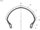
FIG. 1 is a widthwise cross-sectional view illustrating a motorcycle pneumatic tire of the present invention. The illustrated motorcycle pneumatic tire includes: a pair ofbead portions 11; a pair ofside wall portions 12 continuously extending on the respective bead portions; and atread portion 13 toroidally extending between theside wall portions 12. The illustrated motorcycle pneumatic tire also includes: at least one (e.g., 1 or 2)carcass 1 which reinforces the above-described portions between the pair of thebead portions 11; and at least one (e.g., 1 or 2)belt layer 2 which is arranged on a tire radial-direction outer side of thecarcass 1 and is formed by spirally winding a reinforcing cord in a circumferential direction. -
FIG. 2 is a partial development view illustrating one example of a tread pattern of a motorcycle pneumatic tire of the present invention. The illustrated tread pattern is a directional pattern that has a designated rotation direction when mounted on a motorcycle. An arrow inFIG. 2 represents the rotation direction of the tire. - As illustrated, in the tire of the present invention, a first
inclined groove 21, which extends on a tire width-direction outer side from the vicinity of a tire equator CL and is inclined in the same direction as the tire rotation direction, and ashort groove 22, which is arranged on an extension of a tire width-direction outer end of the firstinclined groove 21, are arranged on the tire ground-contact surface.FIG. 3 is an enlarged view illustrating the vicinity of the firstinclined groove 21 and theshort groove 22 arranged on the extension of the firstinclined groove 21. By arranging theshort groove 22 on the extension of the firstinclined groove 21, an effect of improving the drainage performance of a shoulder portion can be obtained. The reason for arranging theshort groove 22 on the extension of the firstinclined groove 21 is also because, for example, when theshort groove 22 is displaced on either side of the tire circumferential direction and is thus not on the extension of the firstinclined groove 21, the rigidity fluctuates and cracking occurs, causing vibration during running. - In the present invention, a tire width-direction
outer end 21A of the firstinclined groove 21 is positioned in the vicinity of a point at 1/4 of a tread width TW from the tire equator CL on the tire width-direction outer side, and a tire width-directioninner end 22B of theshort groove 22 is positioned in a range of 1/4 to 5/16 of the tread width TW from the tire equator CL on the tire width-direction outer side. It is noted here that the phrase "the tire width-directionouter end 21A of the firstinclined groove 21 is positioned in the vicinity of a point of 1/4 of the tread width TW from the tire equator CL on the tire width-direction outer side" means that the tire width-directionouter end 21A of the firstinclined groove 21 exists in a range of ±5% of the tread width TW, being centered at the above-described point of 1/4. Further, in the present invention, the term "tread width TW" means a tire width-direction distance between tread ends TE, which is measured along the ground-contact surface in a state where the tire is fitted to an application rim and inflated to a prescribed internal pressure with no load. The term "application rim" used herein refers to a rim defined by an industrial standard that is valid in each region where the tire is manufactured and used, and the term "prescribed internal pressure" refers to an air pressure that corresponds to the maximum load capacity at the application size prescribed in the industrial standard. The "industrial standard" is, for example, JATMA YEAR BOOK of Japan Automobile Tyre Manufacturers Association (JATMA) in Japan, STANDARD MANUAL of The European Tyre and Rim Technical Organisation (ETRTO) in Europe, or YEAR BOOK of The Tire and Rim Association, Inc. (TRA) in the U.S. - As described above, the drainage performance of a shoulder portion can be improved by arranging the
short groove 22 on the extension of the firstinclined groove 21; however, when aland portion 41 between the firstinclined groove 21 and theshort groove 22 is too close to the shoulder side, the lateral rigidity during turning of the motorcycle cannot be obtained sufficiently. Therefore, in the present invention, the positions of the tire width-directionouter end 21A of the firstinclined groove 21 and the tire width-directioninner end 22B of theshort groove 22 are defined as described above, whereby theland portion 41 is positioned in the range of 1/4 to 5/16 of the tread width TW from the tire equator CL on the tire width-direction outer side, which range where theland portion 41 frequently comes in contact with the ground during turning of the motorcycle. By this, a high lateral rigidity can be ensured during turning of the motorcycle. - In the present invention, the first
inclined groove 21 is arranged such that, as illustrated, the inclination angle thereof with respect to the tire circumferential direction increases toward the tire width-direction outer side. By this, an effect of ensuring the rigidity and the drainage performance in the vicinity of the tire equator CL as well as the lateral rigidity in the tire shoulder portions can be attained. -
FIG. 4 is a schematic cross-sectional view taken along the extending direction of the firstinclined groove 21 and theshort groove 22 arranged on the extension of the firstinclined groove 21. As illustrated, in the present invention, an angle θA formed by a groove wall 21Aw of the tire width-directionouter end 21A of the firstinclined groove 21 with respect to the direction perpendicular to the tire surface, and an angle θB formed by a groove wall 22Bw of the tire width-directioninner end 22B of theshort groove 22 with respect to the direction perpendicular to the tire surface, satisfy a relationship of θA > θB. By this, the lateral rigidity during turning of the motorcycle can be ensured and the drainage performance can be improved, both at a higher level. - Therefore, according to the present invention, by arranging the first
inclined groove 21 and theshort groove 22 that have the above-described constitutions on the ground-contact surface, a motorcycle pneumatic tire in which the wet grip performance during turning of a motorcycle is improved by enhancing the drainage performance, while the lateral rigidity is ensured by securing the steering stability during turning of the motorcycle, can be realized. - From the standpoint of the balance between the lateral rigidity and the drainage performance, the angle θA formed by the groove wall 21Aw of the tire width-direction
outer end 21A of the firstinclined groove 21 with respect to the direction perpendicular to the tire surface, is in a range of preferably 40° or larger, more preferably 42° or larger, but preferably 50° or smaller, more preferably 48° or smaller, and the angle θB formed by the groove wall 22Bw of the tire width-directioninner end 22B of theshort groove 22 with respect to the direction perpendicular to the tire surface is in a range of preferably 15° or larger, more preferably 17° or larger, but preferably 25° or smaller, more preferably 23° or smaller. - Further, in the present invention, a tire width-direction distance w between the tire width-direction
outer end 21A of the firstinclined groove 21 and the tire width-directioninner end 22B of theshort groove 22 is preferably in a range of 7% or greater, particularly 8% or greater, but 13% or less, particularly 12% or less, of the tread half width TW/2. By controlling the tire width-direction distance w between the tire width-directionouter end 21A of the firstinclined groove 21 and the tire width-directioninner end 22B of theshort groove 22 to be in the above-described range, the wet grip performance during turning of the motorcycle can be ensured more certainly. It is noted here that the distance w is a value measured in the same manner as the tread width TW. - Moreover, in the present invention, when the tread width TW is equally divided in eight, it is preferred that, among the thus equally-divided eight regions, the regions of 1/8 to 1/4 and 1/4 to 3/8 of the tread width TW from the tire equator CL on the tire width-direction outer side have the largest number of grooves arranged on the ground-contact surface. By setting the number of grooves to be the largest in these regions, the pattern rigidity on the inner side of the ground-contact surface is reduced during turning of the motorcycle as compared to the pattern rigidity on the outer side of the ground-contact surface; therefore, the shearing force in slippery regions is dispersed, whereby an effect of improving the wet grip performance can be obtained.
- In the present invention, the number of grooves included in each region is determined by measuring the tire width-direction distance between the tire widthwise ends of each groove in each region and counting the number of grooves that are included across 70% or more of the tire width direction of each region. Further, in the present invention, the term "groove" refers to a groove having a maximum groove width of not less than 2 mm or a maximum groove depth of not less than 2 mm, and the term does not encompass, for example, such a shallow groove whose maximum groove width or maximum groove depth does not satisfy the above-described range. In the present invention, the term "groove width" refers to the width of an opening at a cross-section perpendicular to the extending direction of the groove of interest.
- As illustrated, in the tire of the present invention, in addition to the first
inclined groove 21 and theshort groove 22, a second inclined groove 23 and a thirdinclined groove 24, each of which extends from the tire width-direction inner side toward the tire width-direction outer side and is inclined in the same direction as the tire rotation direction, may be arranged on the tire ground-contact surface. As illustrated, together with the firstinclined groove 21 and theshort groove 22, the second inclined groove 23 and the thirdinclined groove 24 may be arranged at substantially equal intervals along the tire circumferential direction, and their inclination angles with respect to the tire circumferential direction increase toward the tire width-direction outer side in the same manner as the first inclined groove. - In the tire of the present invention, as illustrated,
decorative grooves - In the present invention, the arrangement pitch of the inclined grooves and the decorative grooves is not particularly restricted and, for example, the arrangement pitch may be about 1/15 to 1/22 of the whole circumferential length of the tire. Further, in the present invention, the positions of the inclined grooves and the decorative grooves along the tire circumferential direction may be arranged alternately to be shifted, for example, by 1/2 to 1/3 of the arrangement pitch on one side and the other side of the ground-contact surface sandwiching the tire equatorial plane CL.
- In the tire of the present invention, it is important that the arrangement conditions of the grooves provided on the tire ground-contact surface be defined as described above, and this enables to attain the expected effects. The details of other tire structures, materials to be used and the like are not particularly restricted and, for example, the tire of the present invention can be configured as follows.
- As the
belt layer 2, a spiral belt formed by spirally winding an elongated rubber-coated cord obtained by coating a single reinforcing cord with a rubber or a strip-form ply obtained by coating plural reinforcing cords with a rubber and whose cord direction is substantially the same as the tire circumferential direction, can be used. Alternatively, thebelt layer 2 may be composed of two or more inclined belt layers that are arranged such that their cord directions intersect with each other between the layers. The reinforcing cord(s) can be selected as appropriate from steel cords, cords made of organic fibers, such as fibers of aromatic polyamide (aramid, e.g., trade name "KEVLAR(registered trademark)" manufactured by DuPont (trademark)), polyethylene naphthalate (PEN), polyethylene terephthalate (PET), rayon, ZYLON (registered trademark) (poly-p-phenylene benzobisoxazole (PBO) fiber) or aliphatic polyamide (nylon), and cords made of glass fibers, carbon fibers or the like. From the standpoint of ensuring the wear life and the high-speed durability at high levels, it is preferred to use a steel cord. - Further, for example, as illustrated, in the tire of the present invention,
bead cores 3 are each embedded in the pair of thebead portions 11, and thecarcass 1 is folded around thebead cores 3 from the inside to the outside of the tire and thereby anchored. The ends of thecarcass 1 may each be sandwiched from both sides and anchored by bead wires, although this is not illustrated in the drawing. Moreover, an inner liner (not illustrated) is formed as an innermost layer of the tire of the present invention. - The tire of the present invention can be applied as both a front tire and a rear tire of a motorcycle, and the tire of the present invention is particularly suitable as a front tire and may be applied as a tire having either a radial structure or a bias structure.
- The present invention will now be described in more detail by way of Examples thereof.
- In accordance with the conditions shown in the table below, a motorcycle pneumatic radial tire of Example 1 having the cross-sectional structure and the tread pattern as illustrated in
FIGs. 1 and2 was produced at a tire size of MCR120/70ZR17M/C. Thecarcass 1 was provided in two layers, and rayon was used as a reinforcing cord. Further, as thebelt layer 2, a mono-spiral belt obtained by spirally winding a rubber-coated steel cord was used. - In the tire of Example 1, a first inclined groove extending on the tire width-direction outer side from the vicinity of the tire equator and being inclined in the same direction as the tire rotation direction, and a short groove arranged on the extension of the tire width-direction outer end of the first inclined groove were provided on the tire ground-contact surface. In addition, the tire width-direction outer end of the first inclined groove was positioned in the vicinity of a point at 1/4 of the tread width TW from the tire equator on the tire width-direction outer side, and the tire width-direction inner end of the short groove was positioned in a range of 1/4 to 5/16 of the tread width TW from the tire equator on the tire width-direction outer side.
- Motorcycle pneumatic radial tires of other Examples and Comparative Examples were produced by changing the conditions as shown in the tables below. It is noted here that the ratio of the tire width-direction distance (w) between the tire width-direction outer end of the first inclined groove and the tire width-direction inner end of the short groove with respect to the tread half width (TW/2) was set to be 10% in all of the tires.
- The thus obtained test tires were each fitted to a rim having a size of MT5.5×17, mounted on a 1,000-cc motorcycle as its front tire, and then inflated to an internal pressure of 250 kPa. As the rear tire, a commercially available tire having a size of MCR180/55ZR17M/C was used.
- For each of the test tires, an actual driving test was conducted by a professional rider on a test track having a dry surface, and the steering stability during turning was evaluated based on the rider's feeling. The results thereof were indicated as an index, taking the evaluation of Comparative Example 1 as 100. A larger numerical value means a superior and more favorable steering stability.
- For each of the test tires, an actual driving test was conducted by a professional rider on a test track having a wet surface, and the grip performance during turning was evaluated based on the rider's feeling. The results thereof were indicated as an index, taking the evaluation of Comparative Example 1 as 100. A larger numerical value means a superior and more favorable wet grip performance.
- The results of the above-described evaluations are shown together in the tables below.
[Table 1] Example 1 Example 2 Example 3 Example 4 Example 5 Position of short groove On extension of first inclined groove On extension of first inclined groove On extension of first inclined groove On extension of first inclined groove On extension of first inclined groove Angle of groove wall of outer end of first inclined groove, θA (°)*1 45 40 50 45 45 Angle of groove wall of inner end of short groove, θB (°)*2 20 20 20 15 25 Steering stability during turning (index) 110 108 112 108 112 Wet grip performance during turning (index) 110 112 108 112 108 *1) An angle formed by the groove wall of the tire width-direction outer end of the first inclined groove with respect to the direction perpendicular to the tire surface
*2) An angle formed by the groove wall of the tire width-direction inner end of the short groove with respect to the direction perpendicular to the tire surface[Table 2] Comparative Example 1 Comparative Example 2 Comparative Example 3 Comparative Example 4 Comparative Example 5 Position of short groove Out of extension of first inclined groove none On extension of first inclined groove On extension of first inclined groove On extension of first inclined groove Angle of groove wall of outer end of first inclined groove, θA (°)*1 45 45 20 45 20 Angle of groove wall of inner end of short groove, θB (°)*2 20 20 45 45 20 Steering stability during turning (index) 100 110 110 95 98 Wet grip performance during turning (index) 100 95 95 110 105 - As shown in the tables above, it was confirmed that, in Examples, the wet grip performance during turning was improved while the steering stability during turning was ensured.
-
- 1:
- carcass
- 2:
- belt layer
- 3:
- bead core
- 11:
- bead portion
- 12:
- side wall portion
- 13:
- tread portion
- 21:
- first inclined groove
- 21A:
- tire width-direction outer end of first inclined groove
- 21Aw:
- groove wall of tire width-direction outer end of first inclined groove
- 22:
- short groove
- 22B:
- tire width-direction inner end of short groove
- 22Bw:
- groove wall of tire width-direction inner end of short groove
- 23:
- second inclined groove
- 24:
- third inclined groove
- 31, 32:
- decorative groove
- 41:
- land portion
- TE:
- tread end
Claims (3)
- A motorcycle pneumatic tire comprising:a pair of bead portions;a pair of side wall portions continuously extending on the respective bead portions;a tread portion toroidally extending between the side wall portions;at least one carcass reinforcing the respective portions between the pair of the bead portions; anda designated rotation direction when mounted on a motorcycle, whereinthe motorcycle pneumatic tire further comprises, on its ground-contact surface: a first inclined groove extending on a tire width-direction outer side from the vicinity of a tire equator and being inclined in the same direction as the tire rotation direction; and a short groove arranged on an extension of a tire width-direction outer end of the first inclined groove,the tire width-direction outer end of the first inclined groove is positioned in the vicinity of a point at 1/4 of a tread width TW from the tire equator on the tire width-direction outer side, while a tire width-direction inner end of the short groove is positioned in a range of 1/4 to 5/16 of the tread width TW from the tire equator on the tire width-direction outer side,an inclination angle of the first inclined groove with respect to a tire circumferential direction increases toward the tire width-direction outer side, andan angle θA formed by a groove wall of the tire width-direction outer end of the first inclined groove with respect to the direction perpendicular to the tire surface, and an angle θB formed by a groove wall of the tire width-direction inner end of the short groove with respect to the direction perpendicular to the tire surface, satisfy a relationship of θA > θB.
- The motorcycle pneumatic tire according to claim 1, wherein
the angle θA formed by the groove wall of the tire width-direction outer end of the first inclined groove with respect to the direction perpendicular to the tire surface, is in a range of 40° to 50°, and
the angle θB formed by the groove wall of the tire width-direction inner end of the short groove with respect to the direction perpendicular to the tire surface, is in a range of 15° to 25°. - The motorcycle pneumatic tire according to claim 1 or 2, wherein a tire width-direction distance between the tire width-direction outer end of the first inclined groove and the tire width-direction inner end of the short groove is in a range of 7 to 13% of a tread half width TW/2.
Applications Claiming Priority (2)
| Application Number | Priority Date | Filing Date | Title |
|---|---|---|---|
| JP2017138028A JP6851924B2 (en) | 2017-07-14 | 2017-07-14 | Pneumatic tires for motorcycles |
| PCT/JP2018/023880 WO2019012964A1 (en) | 2017-07-14 | 2018-06-22 | Pneumatic tire for motorcycle |
Publications (3)
| Publication Number | Publication Date |
|---|---|
| EP3653403A1 true EP3653403A1 (en) | 2020-05-20 |
| EP3653403A4 EP3653403A4 (en) | 2021-01-20 |
| EP3653403B1 EP3653403B1 (en) | 2021-09-22 |
Family
ID=65001392
Family Applications (1)
| Application Number | Title | Priority Date | Filing Date |
|---|---|---|---|
| EP18831767.1A Active EP3653403B1 (en) | 2017-07-14 | 2018-06-22 | Pneumatic tire for motorcycle |
Country Status (5)
| Country | Link |
|---|---|
| US (1) | US11780269B2 (en) |
| EP (1) | EP3653403B1 (en) |
| JP (1) | JP6851924B2 (en) |
| CN (1) | CN110891801B (en) |
| WO (1) | WO2019012964A1 (en) |
Families Citing this family (1)
| Publication number | Priority date | Publication date | Assignee | Title |
|---|---|---|---|---|
| TWI690434B (en) * | 2019-04-12 | 2020-04-11 | 正新橡膠工業股份有限公司 | Tire with enhanced drainage ability |
Family Cites Families (12)
| Publication number | Priority date | Publication date | Assignee | Title |
|---|---|---|---|---|
| JP2007210384A (en) * | 2006-02-08 | 2007-08-23 | Bridgestone Corp | Pneumatic tire for motorcycle |
| EP2181864B1 (en) | 2008-11-04 | 2011-05-18 | Sumitomo Rubber Industries, Ltd. | Pneumatic tire for motorcycle |
| JP5216620B2 (en) | 2009-02-10 | 2013-06-19 | 株式会社ブリヂストン | Pneumatic tires for motorcycles |
| JP5596580B2 (en) * | 2011-01-28 | 2014-09-24 | 株式会社ブリヂストン | Pneumatic tires for motorcycles |
| JP2012162160A (en) * | 2011-02-04 | 2012-08-30 | Bridgestone Corp | Pneumatic tire for motorcycle |
| JP5965138B2 (en) * | 2011-12-06 | 2016-08-03 | 株式会社ブリヂストン | Pneumatic tires for motorcycles |
| JP5444393B2 (en) * | 2012-03-01 | 2014-03-19 | 住友ゴム工業株式会社 | Motorcycle tires |
| JP2014210470A (en) * | 2013-04-17 | 2014-11-13 | 住友ゴム工業株式会社 | Two-wheeled motor vehicle tire |
| JP6508905B2 (en) | 2014-10-01 | 2019-05-08 | 株式会社ブリヂストン | Motorcycle tire and tire set |
| JP6502689B2 (en) * | 2015-01-30 | 2019-04-17 | 住友ゴム工業株式会社 | Pneumatic tire for motorcycles |
| JP6972986B2 (en) * | 2017-12-04 | 2021-11-24 | 住友ゴム工業株式会社 | Motorcycle tires |
| JP6939495B2 (en) * | 2017-12-11 | 2021-09-22 | 住友ゴム工業株式会社 | Motorcycle tires |
-
2017
- 2017-07-14 JP JP2017138028A patent/JP6851924B2/en active Active
-
2018
- 2018-06-22 CN CN201880046720.8A patent/CN110891801B/en active Active
- 2018-06-22 WO PCT/JP2018/023880 patent/WO2019012964A1/en unknown
- 2018-06-22 EP EP18831767.1A patent/EP3653403B1/en active Active
-
2020
- 2020-01-13 US US16/740,565 patent/US11780269B2/en active Active
Also Published As
| Publication number | Publication date |
|---|---|
| CN110891801B (en) | 2021-07-23 |
| JP2019018676A (en) | 2019-02-07 |
| EP3653403A4 (en) | 2021-01-20 |
| JP6851924B2 (en) | 2021-03-31 |
| US20200148007A1 (en) | 2020-05-14 |
| WO2019012964A1 (en) | 2019-01-17 |
| CN110891801A (en) | 2020-03-17 |
| US11780269B2 (en) | 2023-10-10 |
| EP3653403B1 (en) | 2021-09-22 |
Similar Documents
| Publication | Publication Date | Title |
|---|---|---|
| JP5756486B2 (en) | Pneumatic tire | |
| US20040211501A1 (en) | Pneumatic tire | |
| US10870318B2 (en) | Pneumatic tire | |
| EP2206612A1 (en) | Tire for motor-bicycle | |
| JP7298622B2 (en) | pneumatic tire | |
| US10596860B2 (en) | Pneumatic tire | |
| EP3272553B1 (en) | Motorcycle tire | |
| EP3653403B1 (en) | Pneumatic tire for motorcycle | |
| US11787236B2 (en) | Pneumatic tire for motorcycle | |
| CN107428204B (en) | Motorcycle tyre | |
| JPH04254205A (en) | Pneumatic radial tire for two-wheeler | |
| EP3932695A1 (en) | Motorcycle tire | |
| US20220339975A1 (en) | Tire | |
| US11639076B2 (en) | Motorcycle tire | |
| CN113508043B (en) | Motorcycle tyre | |
| EP3695984B1 (en) | Motorcycle tire | |
| EP3838624A1 (en) | Pneumatic tire | |
| US10940720B2 (en) | Tire for motorcycles | |
| JP2022067950A (en) | Pneumatic tire |
Legal Events
| Date | Code | Title | Description |
|---|---|---|---|
| STAA | Information on the status of an ep patent application or granted ep patent |
Free format text: STATUS: THE INTERNATIONAL PUBLICATION HAS BEEN MADE |
|
| PUAI | Public reference made under article 153(3) epc to a published international application that has entered the european phase |
Free format text: ORIGINAL CODE: 0009012 |
|
| STAA | Information on the status of an ep patent application or granted ep patent |
Free format text: STATUS: REQUEST FOR EXAMINATION WAS MADE |
|
| 17P | Request for examination filed |
Effective date: 20200206 |
|
| AK | Designated contracting states |
Kind code of ref document: A1 Designated state(s): AL AT BE BG CH CY CZ DE DK EE ES FI FR GB GR HR HU IE IS IT LI LT LU LV MC MK MT NL NO PL PT RO RS SE SI SK SM TR |
|
| AX | Request for extension of the european patent |
Extension state: BA ME |
|
| DAV | Request for validation of the european patent (deleted) | ||
| DAX | Request for extension of the european patent (deleted) | ||
| A4 | Supplementary search report drawn up and despatched |
Effective date: 20201216 |
|
| RIC1 | Information provided on ipc code assigned before grant |
Ipc: B60C 11/03 20060101AFI20201211BHEP Ipc: B60C 11/13 20060101ALI20201211BHEP |
|
| RIC1 | Information provided on ipc code assigned before grant |
Ipc: B60C 11/13 20060101ALI20210415BHEP Ipc: B60C 11/03 20060101AFI20210415BHEP |
|
| GRAP | Despatch of communication of intention to grant a patent |
Free format text: ORIGINAL CODE: EPIDOSNIGR1 |
|
| STAA | Information on the status of an ep patent application or granted ep patent |
Free format text: STATUS: GRANT OF PATENT IS INTENDED |
|
| INTG | Intention to grant announced |
Effective date: 20210528 |
|
| GRAS | Grant fee paid |
Free format text: ORIGINAL CODE: EPIDOSNIGR3 |
|
| GRAA | (expected) grant |
Free format text: ORIGINAL CODE: 0009210 |
|
| STAA | Information on the status of an ep patent application or granted ep patent |
Free format text: STATUS: THE PATENT HAS BEEN GRANTED |
|
| AK | Designated contracting states |
Kind code of ref document: B1 Designated state(s): AL AT BE BG CH CY CZ DE DK EE ES FI FR GB GR HR HU IE IS IT LI LT LU LV MC MK MT NL NO PL PT RO RS SE SI SK SM TR |
|
| REG | Reference to a national code |
Ref country code: GB Ref legal event code: FG4D |
|
| REG | Reference to a national code |
Ref country code: DE Ref legal event code: R096 Ref document number: 602018024075 Country of ref document: DE |
|
| REG | Reference to a national code |
Ref country code: IE Ref legal event code: FG4D |
|
| REG | Reference to a national code |
Ref country code: CH Ref legal event code: EP Ref country code: AT Ref legal event code: REF Ref document number: 1432037 Country of ref document: AT Kind code of ref document: T Effective date: 20211015 |
|
| REG | Reference to a national code |
Ref country code: LT Ref legal event code: MG9D |
|
| REG | Reference to a national code |
Ref country code: NL Ref legal event code: MP Effective date: 20210922 |
|
| PG25 | Lapsed in a contracting state [announced via postgrant information from national office to epo] |
Ref country code: NO Free format text: LAPSE BECAUSE OF FAILURE TO SUBMIT A TRANSLATION OF THE DESCRIPTION OR TO PAY THE FEE WITHIN THE PRESCRIBED TIME-LIMIT Effective date: 20211222 Ref country code: HR Free format text: LAPSE BECAUSE OF FAILURE TO SUBMIT A TRANSLATION OF THE DESCRIPTION OR TO PAY THE FEE WITHIN THE PRESCRIBED TIME-LIMIT Effective date: 20210922 Ref country code: BG Free format text: LAPSE BECAUSE OF FAILURE TO SUBMIT A TRANSLATION OF THE DESCRIPTION OR TO PAY THE FEE WITHIN THE PRESCRIBED TIME-LIMIT Effective date: 20211222 Ref country code: LT Free format text: LAPSE BECAUSE OF FAILURE TO SUBMIT A TRANSLATION OF THE DESCRIPTION OR TO PAY THE FEE WITHIN THE PRESCRIBED TIME-LIMIT Effective date: 20210922 Ref country code: RS Free format text: LAPSE BECAUSE OF FAILURE TO SUBMIT A TRANSLATION OF THE DESCRIPTION OR TO PAY THE FEE WITHIN THE PRESCRIBED TIME-LIMIT Effective date: 20210922 Ref country code: SE Free format text: LAPSE BECAUSE OF FAILURE TO SUBMIT A TRANSLATION OF THE DESCRIPTION OR TO PAY THE FEE WITHIN THE PRESCRIBED TIME-LIMIT Effective date: 20210922 Ref country code: FI Free format text: LAPSE BECAUSE OF FAILURE TO SUBMIT A TRANSLATION OF THE DESCRIPTION OR TO PAY THE FEE WITHIN THE PRESCRIBED TIME-LIMIT Effective date: 20210922 |
|
| REG | Reference to a national code |
Ref country code: AT Ref legal event code: MK05 Ref document number: 1432037 Country of ref document: AT Kind code of ref document: T Effective date: 20210922 |
|
| PG25 | Lapsed in a contracting state [announced via postgrant information from national office to epo] |
Ref country code: LV Free format text: LAPSE BECAUSE OF FAILURE TO SUBMIT A TRANSLATION OF THE DESCRIPTION OR TO PAY THE FEE WITHIN THE PRESCRIBED TIME-LIMIT Effective date: 20210922 Ref country code: GR Free format text: LAPSE BECAUSE OF FAILURE TO SUBMIT A TRANSLATION OF THE DESCRIPTION OR TO PAY THE FEE WITHIN THE PRESCRIBED TIME-LIMIT Effective date: 20211223 |
|
| PG25 | Lapsed in a contracting state [announced via postgrant information from national office to epo] |
Ref country code: AT Free format text: LAPSE BECAUSE OF FAILURE TO SUBMIT A TRANSLATION OF THE DESCRIPTION OR TO PAY THE FEE WITHIN THE PRESCRIBED TIME-LIMIT Effective date: 20210922 |
|
| PG25 | Lapsed in a contracting state [announced via postgrant information from national office to epo] |
Ref country code: IS Free format text: LAPSE BECAUSE OF FAILURE TO SUBMIT A TRANSLATION OF THE DESCRIPTION OR TO PAY THE FEE WITHIN THE PRESCRIBED TIME-LIMIT Effective date: 20220122 Ref country code: SK Free format text: LAPSE BECAUSE OF FAILURE TO SUBMIT A TRANSLATION OF THE DESCRIPTION OR TO PAY THE FEE WITHIN THE PRESCRIBED TIME-LIMIT Effective date: 20210922 Ref country code: RO Free format text: LAPSE BECAUSE OF FAILURE TO SUBMIT A TRANSLATION OF THE DESCRIPTION OR TO PAY THE FEE WITHIN THE PRESCRIBED TIME-LIMIT Effective date: 20210922 Ref country code: PT Free format text: LAPSE BECAUSE OF FAILURE TO SUBMIT A TRANSLATION OF THE DESCRIPTION OR TO PAY THE FEE WITHIN THE PRESCRIBED TIME-LIMIT Effective date: 20220124 Ref country code: PL Free format text: LAPSE BECAUSE OF FAILURE TO SUBMIT A TRANSLATION OF THE DESCRIPTION OR TO PAY THE FEE WITHIN THE PRESCRIBED TIME-LIMIT Effective date: 20210922 Ref country code: NL Free format text: LAPSE BECAUSE OF FAILURE TO SUBMIT A TRANSLATION OF THE DESCRIPTION OR TO PAY THE FEE WITHIN THE PRESCRIBED TIME-LIMIT Effective date: 20210922 Ref country code: ES Free format text: LAPSE BECAUSE OF FAILURE TO SUBMIT A TRANSLATION OF THE DESCRIPTION OR TO PAY THE FEE WITHIN THE PRESCRIBED TIME-LIMIT Effective date: 20210922 Ref country code: EE Free format text: LAPSE BECAUSE OF FAILURE TO SUBMIT A TRANSLATION OF THE DESCRIPTION OR TO PAY THE FEE WITHIN THE PRESCRIBED TIME-LIMIT Effective date: 20210922 Ref country code: CZ Free format text: LAPSE BECAUSE OF FAILURE TO SUBMIT A TRANSLATION OF THE DESCRIPTION OR TO PAY THE FEE WITHIN THE PRESCRIBED TIME-LIMIT Effective date: 20210922 Ref country code: AL Free format text: LAPSE BECAUSE OF FAILURE TO SUBMIT A TRANSLATION OF THE DESCRIPTION OR TO PAY THE FEE WITHIN THE PRESCRIBED TIME-LIMIT Effective date: 20210922 |
|
| REG | Reference to a national code |
Ref country code: DE Ref legal event code: R097 Ref document number: 602018024075 Country of ref document: DE |
|
| PG25 | Lapsed in a contracting state [announced via postgrant information from national office to epo] |
Ref country code: DK Free format text: LAPSE BECAUSE OF FAILURE TO SUBMIT A TRANSLATION OF THE DESCRIPTION OR TO PAY THE FEE WITHIN THE PRESCRIBED TIME-LIMIT Effective date: 20210922 |
|
| PLBE | No opposition filed within time limit |
Free format text: ORIGINAL CODE: 0009261 |
|
| STAA | Information on the status of an ep patent application or granted ep patent |
Free format text: STATUS: NO OPPOSITION FILED WITHIN TIME LIMIT |
|
| 26N | No opposition filed |
Effective date: 20220623 |
|
| PG25 | Lapsed in a contracting state [announced via postgrant information from national office to epo] |
Ref country code: SI Free format text: LAPSE BECAUSE OF FAILURE TO SUBMIT A TRANSLATION OF THE DESCRIPTION OR TO PAY THE FEE WITHIN THE PRESCRIBED TIME-LIMIT Effective date: 20210922 |
|
| PG25 | Lapsed in a contracting state [announced via postgrant information from national office to epo] |
Ref country code: MC Free format text: LAPSE BECAUSE OF FAILURE TO SUBMIT A TRANSLATION OF THE DESCRIPTION OR TO PAY THE FEE WITHIN THE PRESCRIBED TIME-LIMIT Effective date: 20210922 Ref country code: IT Free format text: LAPSE BECAUSE OF FAILURE TO SUBMIT A TRANSLATION OF THE DESCRIPTION OR TO PAY THE FEE WITHIN THE PRESCRIBED TIME-LIMIT Effective date: 20210922 |
|
| REG | Reference to a national code |
Ref country code: CH Ref legal event code: PL |
|
| REG | Reference to a national code |
Ref country code: BE Ref legal event code: MM Effective date: 20220630 |
|
| GBPC | Gb: european patent ceased through non-payment of renewal fee |
Effective date: 20220622 |
|
| PG25 | Lapsed in a contracting state [announced via postgrant information from national office to epo] |
Ref country code: LU Free format text: LAPSE BECAUSE OF NON-PAYMENT OF DUE FEES Effective date: 20220622 Ref country code: LI Free format text: LAPSE BECAUSE OF NON-PAYMENT OF DUE FEES Effective date: 20220630 Ref country code: IE Free format text: LAPSE BECAUSE OF NON-PAYMENT OF DUE FEES Effective date: 20220622 Ref country code: CH Free format text: LAPSE BECAUSE OF NON-PAYMENT OF DUE FEES Effective date: 20220630 |
|
| PG25 | Lapsed in a contracting state [announced via postgrant information from national office to epo] |
Ref country code: GB Free format text: LAPSE BECAUSE OF NON-PAYMENT OF DUE FEES Effective date: 20220622 Ref country code: BE Free format text: LAPSE BECAUSE OF NON-PAYMENT OF DUE FEES Effective date: 20220630 |
|
| P01 | Opt-out of the competence of the unified patent court (upc) registered |
Effective date: 20230531 |
|
| PGFP | Annual fee paid to national office [announced via postgrant information from national office to epo] |
Ref country code: FR Payment date: 20230628 Year of fee payment: 6 Ref country code: DE Payment date: 20230620 Year of fee payment: 6 |
|
| PG25 | Lapsed in a contracting state [announced via postgrant information from national office to epo] |
Ref country code: SM Free format text: LAPSE BECAUSE OF FAILURE TO SUBMIT A TRANSLATION OF THE DESCRIPTION OR TO PAY THE FEE WITHIN THE PRESCRIBED TIME-LIMIT Effective date: 20210922 Ref country code: MK Free format text: LAPSE BECAUSE OF FAILURE TO SUBMIT A TRANSLATION OF THE DESCRIPTION OR TO PAY THE FEE WITHIN THE PRESCRIBED TIME-LIMIT Effective date: 20210922 Ref country code: CY Free format text: LAPSE BECAUSE OF FAILURE TO SUBMIT A TRANSLATION OF THE DESCRIPTION OR TO PAY THE FEE WITHIN THE PRESCRIBED TIME-LIMIT Effective date: 20210922 |