EP3653389A1 - Liquid container and liquid ejecting apparatus - Google Patents
Liquid container and liquid ejecting apparatus Download PDFInfo
- Publication number
- EP3653389A1 EP3653389A1 EP19208268.3A EP19208268A EP3653389A1 EP 3653389 A1 EP3653389 A1 EP 3653389A1 EP 19208268 A EP19208268 A EP 19208268A EP 3653389 A1 EP3653389 A1 EP 3653389A1
- Authority
- EP
- European Patent Office
- Prior art keywords
- liquid
- liquid storage
- storage section
- case
- section
- Prior art date
- Legal status (The legal status is an assumption and is not a legal conclusion. Google has not performed a legal analysis and makes no representation as to the accuracy of the status listed.)
- Granted
Links
Images








Classifications
-
- B—PERFORMING OPERATIONS; TRANSPORTING
- B41—PRINTING; LINING MACHINES; TYPEWRITERS; STAMPS
- B41J—TYPEWRITERS; SELECTIVE PRINTING MECHANISMS, i.e. MECHANISMS PRINTING OTHERWISE THAN FROM A FORME; CORRECTION OF TYPOGRAPHICAL ERRORS
- B41J2/00—Typewriters or selective printing mechanisms characterised by the printing or marking process for which they are designed
- B41J2/005—Typewriters or selective printing mechanisms characterised by the printing or marking process for which they are designed characterised by bringing liquid or particles selectively into contact with a printing material
- B41J2/01—Ink jet
- B41J2/17—Ink jet characterised by ink handling
- B41J2/175—Ink supply systems ; Circuit parts therefor
- B41J2/17503—Ink cartridges
-
- B—PERFORMING OPERATIONS; TRANSPORTING
- B41—PRINTING; LINING MACHINES; TYPEWRITERS; STAMPS
- B41J—TYPEWRITERS; SELECTIVE PRINTING MECHANISMS, i.e. MECHANISMS PRINTING OTHERWISE THAN FROM A FORME; CORRECTION OF TYPOGRAPHICAL ERRORS
- B41J2/00—Typewriters or selective printing mechanisms characterised by the printing or marking process for which they are designed
- B41J2/005—Typewriters or selective printing mechanisms characterised by the printing or marking process for which they are designed characterised by bringing liquid or particles selectively into contact with a printing material
- B41J2/01—Ink jet
- B41J2/17—Ink jet characterised by ink handling
- B41J2/175—Ink supply systems ; Circuit parts therefor
- B41J2/17503—Ink cartridges
- B41J2/17556—Means for regulating the pressure in the cartridge
-
- B—PERFORMING OPERATIONS; TRANSPORTING
- B41—PRINTING; LINING MACHINES; TYPEWRITERS; STAMPS
- B41J—TYPEWRITERS; SELECTIVE PRINTING MECHANISMS, i.e. MECHANISMS PRINTING OTHERWISE THAN FROM A FORME; CORRECTION OF TYPOGRAPHICAL ERRORS
- B41J2/00—Typewriters or selective printing mechanisms characterised by the printing or marking process for which they are designed
- B41J2/005—Typewriters or selective printing mechanisms characterised by the printing or marking process for which they are designed characterised by bringing liquid or particles selectively into contact with a printing material
- B41J2/01—Ink jet
- B41J2/135—Nozzles
- B41J2/14—Structure thereof only for on-demand ink jet heads
-
- B—PERFORMING OPERATIONS; TRANSPORTING
- B41—PRINTING; LINING MACHINES; TYPEWRITERS; STAMPS
- B41J—TYPEWRITERS; SELECTIVE PRINTING MECHANISMS, i.e. MECHANISMS PRINTING OTHERWISE THAN FROM A FORME; CORRECTION OF TYPOGRAPHICAL ERRORS
- B41J2/00—Typewriters or selective printing mechanisms characterised by the printing or marking process for which they are designed
- B41J2/005—Typewriters or selective printing mechanisms characterised by the printing or marking process for which they are designed characterised by bringing liquid or particles selectively into contact with a printing material
- B41J2/01—Ink jet
- B41J2/17—Ink jet characterised by ink handling
- B41J2/175—Ink supply systems ; Circuit parts therefor
- B41J2/17503—Ink cartridges
- B41J2/17513—Inner structure
-
- B—PERFORMING OPERATIONS; TRANSPORTING
- B41—PRINTING; LINING MACHINES; TYPEWRITERS; STAMPS
- B41J—TYPEWRITERS; SELECTIVE PRINTING MECHANISMS, i.e. MECHANISMS PRINTING OTHERWISE THAN FROM A FORME; CORRECTION OF TYPOGRAPHICAL ERRORS
- B41J2/00—Typewriters or selective printing mechanisms characterised by the printing or marking process for which they are designed
- B41J2/005—Typewriters or selective printing mechanisms characterised by the printing or marking process for which they are designed characterised by bringing liquid or particles selectively into contact with a printing material
- B41J2/01—Ink jet
- B41J2/17—Ink jet characterised by ink handling
- B41J2/175—Ink supply systems ; Circuit parts therefor
- B41J2/17503—Ink cartridges
- B41J2/1752—Mounting within the printer
-
- B—PERFORMING OPERATIONS; TRANSPORTING
- B41—PRINTING; LINING MACHINES; TYPEWRITERS; STAMPS
- B41J—TYPEWRITERS; SELECTIVE PRINTING MECHANISMS, i.e. MECHANISMS PRINTING OTHERWISE THAN FROM A FORME; CORRECTION OF TYPOGRAPHICAL ERRORS
- B41J2/00—Typewriters or selective printing mechanisms characterised by the printing or marking process for which they are designed
- B41J2/005—Typewriters or selective printing mechanisms characterised by the printing or marking process for which they are designed characterised by bringing liquid or particles selectively into contact with a printing material
- B41J2/01—Ink jet
- B41J2/17—Ink jet characterised by ink handling
- B41J2/175—Ink supply systems ; Circuit parts therefor
- B41J2/17503—Ink cartridges
- B41J2/17553—Outer structure
-
- B—PERFORMING OPERATIONS; TRANSPORTING
- B41—PRINTING; LINING MACHINES; TYPEWRITERS; STAMPS
- B41J—TYPEWRITERS; SELECTIVE PRINTING MECHANISMS, i.e. MECHANISMS PRINTING OTHERWISE THAN FROM A FORME; CORRECTION OF TYPOGRAPHICAL ERRORS
- B41J2/00—Typewriters or selective printing mechanisms characterised by the printing or marking process for which they are designed
- B41J2/005—Typewriters or selective printing mechanisms characterised by the printing or marking process for which they are designed characterised by bringing liquid or particles selectively into contact with a printing material
- B41J2/01—Ink jet
- B41J2/17—Ink jet characterised by ink handling
- B41J2/195—Ink jet characterised by ink handling for monitoring ink quality
-
- B—PERFORMING OPERATIONS; TRANSPORTING
- B41—PRINTING; LINING MACHINES; TYPEWRITERS; STAMPS
- B41J—TYPEWRITERS; SELECTIVE PRINTING MECHANISMS, i.e. MECHANISMS PRINTING OTHERWISE THAN FROM A FORME; CORRECTION OF TYPOGRAPHICAL ERRORS
- B41J2/00—Typewriters or selective printing mechanisms characterised by the printing or marking process for which they are designed
- B41J2/005—Typewriters or selective printing mechanisms characterised by the printing or marking process for which they are designed characterised by bringing liquid or particles selectively into contact with a printing material
- B41J2/01—Ink jet
- B41J2/135—Nozzles
- B41J2/14—Structure thereof only for on-demand ink jet heads
- B41J2002/14403—Structure thereof only for on-demand ink jet heads including a filter
Definitions
- the present disclosure relates to a liquid container and a liquid ejecting apparatus.
- an ink path through which the ink passes is formed in an ink pack accommodated in the ink cartridge.
- a tight-contact preventing member is provided in an ink pack to prevent both inner surfaces of the ink pack from coming from tight contact with each other. Due to the tight-contact preventing member, an ink flow path is formed.
- an ink path is formed by expanding part of an ink pack toward the outside by press-molding.
- ink may be left in the ink path formed by the tight-contact preventing member or by press-molding. Therefore, there is a demand for a technology that can reduce the amount of liquid remaining in a liquid container without using a tight-contact preventing member or performing press-molding.
- a first aspect of the present disclosure provides a liquid container from which a liquid can be supplied to a liquid ejecting head in a liquid ejecting apparatus.
- This liquid container has a liquid storage body that stores the liquid and also has a case that stores the liquid storage body.
- the liquid storage body has a liquid storage section formed like a bag by joining the edges of opposing films together and also has a liquid supply section that can supply the liquid from the interior of the liquid storage section to its outside.
- the liquid storage section In a state in which the liquid storage section is filled with the liquid and the liquid storage body is installed in the liquid ejecting apparatus, at least part of the upper edge of the liquid storage section and at least part of the lower edge of the liquid storage section are in contact with the case and a first inner surface of the liquid storage section and its second inner surface opposite to the first inner surface are separated from each other.
- the liquid storage section is structured so that as the liquid is supplied, the first inner surface and second inner surface gradually approach each other and, at the same time, come into contact with each other from top to bottom, forming, at the bottom of the interior of the liquid storage section, a liquid flow path through which the liquid flows from the liquid storage section to the liquid supply section.
- a second aspect of the present disclosure provides a liquid ejecting apparatus.
- This liquid ejecting apparatus has the liquid container in the above aspect and a liquid ejecting head that ejects the liquid supplied from the liquid container.
- FIG. 1 schematically illustrates the structure of a liquid ejecting system 1 in a first embodiment of the present disclosure.
- the X-axis, Y-axis, and Z-axis which are three spatial axes orthogonal to one another, are drawn.
- the arrows of the X-axis, Y-axis, and Z-axis respectively indicate positive directions along the X-axis, Y-axis, and Z-axis.
- the positive directions along the X-axis, Y-axis, and Z-axis are respectively referred to as the +X direction, +Y direction, and +Z direction.
- Directions opposite to the directions indicated by the arrows of the X-axis, Y-axis, and Z-axis are negative directions along the X-axis, Y-axis, and Z-axis.
- the negative directions along the X-axis, Y-axis, and Z-axis are respectively referred to as the -X direction, -Y direction, and -Z direction.
- directions along the X-axis, Y-axis, and Z-axis are positive or negative, these directions are respectively referred to simply as the X-direction, Y-direction, and Z-direction.
- the directions of the X-axis, Y-axis, and Z-axis indicated in the drawings other than FIG. 1 match the directions of the X-axis, Y-axis, and Z-axis in FIG. 1 .
- the Z axis is an axis along the direction of the force of gravity or the vertical direction and the -Z direction is the direction of the force of gravity or the vertical direction.
- the liquid ejecting system 1 has a printer 20 as a liquid ejecting apparatus and also has four cartridges denoted 4C, 4M, 4Y, and 4K as liquid containers.
- the printer 20 is an ink jet printer that ejects an ink used as a liquid from a recording head 225 used as a liquid ejecting head.
- the four cartridges 4C, 4M, 4Y, and 4K are referred to without a distinction, they will be assigned reference numeral 4.
- the +Z direction is upward in the vertical direction and the -Z direction is downward in the vertical direction.
- the state in which the liquid ejecting system 1 and printer 20 are in use refers to a state in which the liquid ejecting system 1 is installed on a horizontal installation surface defined by the X direction and Y direction.
- the printer 20 has a main case 212 shaped like a substantially rectangular box and also has a controller 230 disposed in the main case 212.
- the controller 230 controls the printing operation of the printer 20 and other various operations and transmits and receives signals to and from the cartridges 4.
- a platen 213 is disposed so as to be along the X direction, which is the longitudinal direction of the main case 212.
- the platen 213 is a pedestal that supports recoding paper P, which is a target to which ejection is directed.
- the recoding paper P is supplied by a paper feed mechanism (not illustrated) along a sub-scanning direction orthogonal to a main scanning direction.
- the main scanning direction is the X direction
- the sub-scanning direction is the Y direction.
- the printer 20 further has a guide shaft 214, a carriage 215, a driving pulley 216, a driven pulley 217, and a carriage motor 218.
- the guide shaft 214 is positioned more on the +Z direction side than is the platen 213.
- the guide shaft 214 is a rod-like member along the main scanning direction.
- the carriage 215 is supported by the guide shaft 214 so as to be movable along the guide shaft 214.
- the driving pulley 216 and driven pulley 217 are rotatably disposed at positions corresponding to both ends of the guide shaft 214, the positions being more on the -Y direction side than is the guide shaft 214.
- the carriage motor 218 is linked to the driving pulley 216.
- An endless timing belt 219 that supports the carriage 215 is passed between the driving pulley 216 and the driven pulley 217.
- the carriage 215 can move bidirectionally in the main scanning direction along the guide shaft 214.
- the recording head 225 is structured so that it can move bidirectionally in the main scanning direction, this is not a limitation.
- the recording head 225 may be a line head that extends along the X direction and the position of which is fixed.
- the printer 20 further has a cartridge installation section 6 in which the cartridges 4 are detachably installed.
- the cartridge installation section 6 is also referred to as the holder.
- the cartridge installation section 6 is disposed inside the main case 212.
- the main case 212 is structured so that part of it can be opened and closed. When this openable and closable part is opened, the cartridge 4 can be attached to and detached from the cartridge installation section 6.
- the cartridge installation section 6 is disposed inside the main case 212, this is not a limitation.
- the whole or part of the cartridge installation section 6 may be outside the main case 212.
- the cartridge installation section 6 detachably accommodates the four cartridges 4C, 4M, 4K, and 4Y.
- the cartridge 4K stores a black ink.
- the cartridge 4C stores a cyan ink.
- the cartridge 4M stores a magenta ink.
- the cartridge 4Y stores a yellow ink.
- Each type of ink is a pigmented ink that includes pigment particles and a dispersant such as water.
- the printer 20 has four liquid flow paths 223 in correspondence to the four cartridges 4C, 4M, 4Y, and 4K.
- Each liquid flow path 223 is a tube.
- Each liquid flow path 223 makes the relevant cartridge 4 and recording head 225 communicate with each other.
- the cartridge 4 When installed in the cartridge installation section 6, the cartridge 4 is coupled to the upstream end of the relevant liquid flow path 223.
- the downstream end of the liquid flow path 223 is coupled to the upstream end of a valve unit 224 mounted on the carriage 215.
- the downstream side of the valve unit 224 is coupled to the recording head 225 disposed on the lower surface of the carriage 215. That is, the ink stored in the cartridge 4 passes through the liquid flow path 223 and into the recording head 225.
- a home position HP to which the recording head 225 is retracted, is provided between the cartridge installation section 6 and the platen 213. At this home position HP, various types of maintenance processing such as cleaning are performed for the recording head 225 before printing starts.
- the printer 20 further has a pressuring mechanism 280 that supplies a pressurized fluid to each cartridge 4.
- the pressuring mechanism 280 is disposed inside the main case 212.
- the pressuring mechanism 280 has a pressurizing pump 226, from which pressurized air is supplied as the pressurized fluid, and a plurality of fluid flow paths 227, through which the pressurized air is supplied to the cartridges 4.
- the pressurizing pump 226 is coupled to the upstream ends of the fluid flow paths 227.
- Each fluid flow path 227 is a tube.
- the fluid flow paths 227 branch from a distributor 228 provided at the downstream of the pressurizing pump 226.
- the downstream end of each branching fluid flow path 227 is coupled to the relevant cartridge 4.
- the controller 230 controls the operation of the pressurizing pump 226 to supply the pressurized fluids to the cartridges 4 through the fluid flow paths 227.
- Each fluid flow path 227 allows a flow of pressurized air used to supply the ink stored in the relevant cartridge 4 to the recording head 225.
- the liquid fluid flow paths 227K, 227C, 227M, and 227Y allow pressurized air to flow into pressurizing chambers, which will be described later, in the cartridges 4.
- pressurizing chambers which will be described later, in the cartridges 4.
- a single pressurizing pump 226 common to the liquid fluid flow paths 227K, 227C, 227M, and 227Y is used to supply pressurized air to them, this is not a limitation.
- a plurality of pressurizing pumps 226 may be provided in correspondence to the liquid fluid flow paths 227K, 227C, 227M, and 227Y.
- FIG. 2 is a perspective view illustrating the outside shape of the cartridge installation section 6.
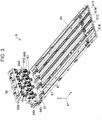
- FIG. 3 is another perspective view illustrating the outside shape of the cartridge installation section 6. In FIG. 3 , part of the structure of the cartridge installation section 6 is omitted so that the interior of the cartridge installation section 6 can be viewed.
- Each cartridge 4 is installed in the cartridge installation section 6 in the -Y direction and is detached from the cartridge installation section 6 in the +Y direction.
- a cartridge storage chamber 61 in which the cartridges 4 are accommodated is formed in the cartridge installation section 6 from six wall portions described later.
- the cartridge storage chamber 61 is shaped like a substantially rectangular parallelepiped.
- the cartridge storage chamber 61 includes four portions in each of which one of the four cartridges 4C, 4M, 4Y, and 4K is accommodated. Each portion is also referred to as a slot. Specifically, as illustrated in FIG. 2 , a cartridge storage chamber 61 in which the cartridges 4 are accommodated is formed in the cartridge installation section 6 from six wall portions described later.
- the cartridge storage chamber 61 is shaped like a substantially rectangular parallelepiped.
- the cartridge storage chamber 61 includes four portions in each of which one of the four cartridges 4C, 4M, 4Y, and 4K is accommodated. Each portion is also referred to as a slot. Specifically, as illustrated in FIG.
- the portion in which the cartridge 4K is accommodated is referred to as the slot 61K
- the portion in which the cartridge 4C is accommodated is referred to as the slot 61C
- the portion in which the cartridge 4M is accommodated is referred to as the slot 61M
- the portion in which the cartridge 4Y is accommodated is referred to as the slot 61Y.
- the cartridge installation section 6 has an apparatus-side front wall portion 62, a first apparatus-side side wall portion 63, and a second apparatus-side side wall portion 64.
- the cartridge installation section 6 also has a third apparatus-side side wall portion 65 and a fourth apparatus-side side wall portion 66.
- the cartridge storage chamber 61 is defined by these five wall portions 62, 63, 64, 65, and 66.
- the outside shape of each of the five wall portions 62, 63, 64, 65, and 66 is substantially rectangular.
- the cartridge storage chamber 61 has an opening 61A at a position opposite to the apparatus-side front wall portion 62.
- the apparatus-side front wall portion 62 is positioned more on the -Y direction side than is the cartridge storage chamber 61.
- the apparatus-side front wall portion 62 is a perpendicular wall portion.
- the cartridge installation section 6 has a liquid supply mechanism 640 and a liquid supply pressurizing section 67.
- the liquid supply mechanism 640 and liquid supply pressurizing section 67 are disposed in the apparatus-side front wall portion 62.
- One liquid supply mechanism 640 and one liquid supply pressurizing section 67 are provided for each of the slots 61C, 61M, 61Y, and 61K in correspondence to each of the cartridges 4C, 4M, 4Y, and 4K.
- the liquid supply mechanism 640 has a cover member 650 and a liquid entrance 643.
- the liquid entrance 643 is used to allow the ink in the cartridge 4 to flow into the printer 20.
- the liquid entrance 643 is like a tube having a central axis extending along the Y direction.
- the liquid entrance 643 is coupled to the cartridge 4.
- the cover member 650 encloses the periphery of the liquid entrance 643 about the central axis of the liquid entrance 643.
- the cover member 650 reduces the possibility that ink scatters to the outside when the cartridge 4 is attached or detached.
- the cover member 650 is urged in the +Y direction by an urging member (not illustrated), such as a coil spring, included in the liquid supply mechanism 640.
- the cover member 650 is structured so as to be movable along the Y direction. In the attachment of the cartridge 4, the cartridge 4 abuts the cover member 650. Then, the cover member 650 moves in the -Y direction against the urging force of the urging member.
- the end of the liquid entrance 643 on the +Y direction side protrudes from the cover member 650 in the +Y direction and is coupled to the cartridge 4.
- the liquid supply pressurizing section 67 is a tubular member through which pressurized air flows, the pressurized air being a pressurized fluid that supplies the ink in the cartridge 4 to the recording head 225.
- the liquid supply pressurizing section 67 is coupled to the downstream end of the liquid fluid flow path 227K, 227C, 227M, or 227Y, whichever is applicable. With the cartridge 4 installed, the liquid supply pressurizing section 67 is coupled to the cartridge 4.
- a tubular seal member is provided on the inner circumferential surface of the liquid supply pressurizing section 67. This seal member is formed from, for example, rubber.
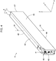
- FIG. 4 is perspective view illustrating the outside shape of the cartridge 4.
- FIG. 5 is an exploded perspective view of the cartridge 4.
- the cartridge 4 is a liquid container from which an ink can be supplied to the recording head 225 in the printer 20 as a liquid.
- the X axis, Y axis, and Z axis are indicated in a state in which the cartridges 4 are installed in the printer 20.
- the X axis, Y axis, and Z axis are indicated as necessary in a state in which the cartridge 4K is installed in the printer 20.
- FIGs. 1 is perspective view illustrating the outside shape of the cartridge 4.
- FIG. 5 is an exploded perspective view of the cartridge 4.
- the cartridge 4 is a liquid container from which an ink can be supplied to the recording head 225 in the printer 20 as a liquid.
- the X axis, Y axis, and Z axis are indicated in a state in which the cartridges 4 are installed in the printer 20.
- the structure of the cartridge 4C is illustrated as the structure of the cartridge 4.
- the structures of the four cartridges 4C, 4M, 4Y, and 4K are substantially the same.
- the cartridge 4K has a larger width in the X direction than the other cartridges 4C, 4M and 4Y.
- the outside shape of the cartridge 4 is a substantially rectangular parallelepiped as illustrated in FIG. 4 .
- the dimension in the Y direction is smallest, followed by the dimension in the Z direction and the dimension in the X direction in that order.
- the X direction is also referred to as the width direction of the cartridge 4, and the Z direction is also referred to as the height direction of the cartridge 4.
- the cartridge 4 has a case 8 forming an outer shell.
- the case 8 is a cabinet formed by being molded from a polypropylene resin, polystyrene resin, or other synthetic resin.
- the cartridge 4 has a front wall 42, a rear wall 47, a top wall 43, a bottom wall 44, a first side wall 45, and a second side wall 46.
- the cartridge 4 further has a second front wall 41 positioned closer to the rear wall 47 than is the front wall 42.
- the second front wall 41 and front wall 42 face in the -Y direction, which is the installation direction.
- the front wall 42 and rear wall 47 are opposite to each other in the Y direction.
- the front wall 42 is positioned on the -Y direction side, and the rear wall 47 is positioned on the +Y direction side.
- the top wall 43 and bottom wall 44 cross the front wall 42 and rear wall 47, and are opposite to each other in the Z direction.
- the top wall 43 is positioned on the +Z direction side, and the bottom wall 44 is positioned on the -Z direction side.
- the first side wall 45 and second side wall 46 cross the front wall 42, rear wall 47, top wall 43, and bottom wall 44, and are opposite to each other in the X direction.
- the first side wall 45 is positioned on the +X direction side
- the second side wall 46 is positioned on the -X direction side.
- this specification when two walls cross each other, this implies any one of a state in which the two walls actually cross each other, a state in which an extension of one of the two walls crosses the other wall, and a state in which extensions of the two walls cross each other.
- the front wall 42 is formed at a protrusion 48, which protrudes from the second front wall 41 in the -Y direction.
- the shape of the front wall 42 is substantially a rectangle having a larger dimension in the Z direction than in the X direction. With the cartridge 4 installed, the front wall 42 faces the apparatus-side front wall portion 62 illustrated in FIG. 3 .
- the cartridge 4 has a liquid storage body 410 that stores an ink and also has the case 8 in which the liquid storage body 410 is placed, as illustrated in FIG. 5 .
- the state in which the cartridge 4 is installed in the printer 20 is also a state in which the liquid storage body 410 accommodated in the cartridge 4 is installed in the printer 20.
- the case 8 is composed of a first case 5 and a second case 7.
- the first case 5 and second case 7 are formed by being molded from a synthetic resin.
- the first case 5 has a concave shape having an opening in the +X direction.
- the first case 5 mainly forms the front wall 42, top wall 43, bottom wall 44, second side wall 46, rear wall 47, second front wall 41, and protrusion 48.
- a seat member 430 is joined to an end face 59 that defines the opening of the first case 5.
- the seat member 430 is formed from a thin film.
- the seat member 430 is airtightly joined to the end face 59 that defines the opening of the first case 5 so as to seal the opening.
- an inner chamber 440 in which a liquid storage section 412 is accommodated is defined.
- This inner chamber 440 receives a supply of pressurized air that passes through the fluid flow path 227.
- the supplied pressurized air presses the liquid storage section 412.
- the ink stored in the liquid storage section 412 is pressurized.
- the inner chamber 440 also functions as a pressurizing chamber that pressurizes the ink in the liquid storage section 412 to supply the ink in the liquid storage section 412 to the printer 20.
- the second case 7 is attached to the first case 5 so as to cover the seat member 430.
- the second case 7 mainly forms the first side wall 45.
- the liquid storage body 410 and seat member 430 are protected by the first case 5 and second case 7, suppressing the liquid storage body 410 and seat member 430 from being damaged.
- the liquid storage body 410 has the liquid storage section 412 and a liquid supply section 414.
- the liquid storage section 412 stores an ink.
- the liquid storage section 412 is formed from a flexible film.
- the liquid storage section 412 is in the form of a bag.
- the volume of the liquid storage section 412 is reduced as the ink in the liquid storage section 412 is consumed.
- the whole of the liquid storage section 412 may not be formed from a flexible member. At least part of the liquid storage section 412 may be formed from a flexible member.
- the liquid supply section 414 can supply an ink from the interior of the liquid storage section 412 to its outside.
- the liquid supply section 414 allows the ink stored in the liquid storage section 412, which functions as a liquid supply source, to flow toward the printer 20.
- the liquid supply section 414 and liquid entrance 643 are coupled together.
- the ink in the liquid storage section 412 flows through the liquid supply section 414 and liquid entrance 643 and into the recording head 225 in the printer 20.
- the liquid supply section 414 has a central axis CL.
- the central axis CL extends in parallel to the -Y direction, in which the cartridge 4 is installed.
- the liquid supply section 414 internally has a tubular member through which an ink can flow.
- the liquid supply section 414 is coupled to the end of the liquid storage section 412 in the -Y direction.
- a valve mechanism is provided in the liquid supply section 414. This valve mechanism is opened when the liquid entrance 643 is coupled to the liquid supply section 414.
- FIG. 6 is a side view of the liquid storage section 412.
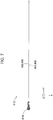
- FIG. 7 is a top view of the liquid storage section 412.
- FIG. 8 is a front view of the liquid storage section 412.
- the liquid storage section 412 is formed by joining the ends of two films, a first film 451 and a second film 452, which are opposite to each other in the X direction, by thermal fusion or the like.
- the first film 451 and second film 452 have the same shape and are formed from the same material.
- the width MW of a portion over which the first film 451 and second film 452 are joined together is 4.5 mm.
- the first film 451 and second film 452 are referred to without a distinction, they will be referred to as a film 450.
- the liquid storage section 412 has an elongated shape having a larger dimension in the Y direction than in the Z direction.
- the liquid supply section 414 is attached at the center of an end of the liquid storage section 412, the center being in the Z direction, the end being in the -Y direction, so that the liquid supply section 414 is interposed between the first film 451 and the second film 452.
- the liquid storage section 412 has a substantially octagonal shape having a side along the top wall 43 and a side along the bottom wall 44. In other words, the liquid storage section 412 has a shape resulting from cutting the four corners of a quadrangular shape.
- the shape of the liquid storage section 412 is not limited to an octagon if the liquid storage section 412 has a side along the top wall 43 and a side along the bottom wall 44.
- the liquid storage section 412 may have another polygonal shape such as a rectangular or hexagonal shape. Sides other than the side along the top wall 43 and the side along the bottom wall 44 may be curved lines.
- FIG. 9 illustrates a placement of the liquid storage section 412 in the case 8.
- FIG. 9 schematically illustrates an end face of the cartridge 4 in a state in which the liquid storage section 412 is filled with an ink and the liquid storage body 410 is installed in the printer 20.
- the end face in this schematic drawing is the end face taken along line IX-IX in FIG. 4 .
- the seat member 430 is appropriately omitted to simply the drawings. As illustrated in FIG.
- the liquid storage section 412 in a state in which the liquid storage section 412 is filled with an ink and the liquid storage body 410 is installed in the printer 20, at least part of the upper edge 412A of the liquid storage section 412 and at least part of the lower edge 412B of the liquid storage section 412 are in contact with the case 8.
- the liquid storage section 412 is substantially octagonal as illustrated in FIG. 6 . In this embodiment, therefore, the whole of the upper edge 412A of the liquid storage section 412 is not in contact with the case 8, but only the central portion of the upper edge 412A of the liquid storage section 412 in the Y direction is in contact with case 8.
- the whole of the lower edge 412B of the liquid storage section 412 is not in contact with the case 8, but only the central portion of the lower edge 412B of the liquid storage section 412 in the Y direction is in contact with case 8.
- the liquid storage section 412 is rectangular, the whole of the upper edge 412A of the liquid storage section 412 and the whole of the lower edge 412B of the liquid storage section 412 are in contact with the case 8.
- the upper edge 412A of the liquid storage section 412 comes into contact with the case 8.
- the lower edge 412B of the liquid storage section 412 comes into contact with the case 8.
- the upper edge 412A and lower edge 412B of the liquid storage section 412 are in contact with the case 8 in a state in which they are curved so as to face in the +X direction toward which the first case 5 is open.
- a first inner surface 412C of the liquid storage section 412 and its second inner surface 412D opposite to the first inner surface 412C are separated from each other.
- the first inner surface 412C is the inner surface of the first film 451 disposed on the +X direction side
- the second inner surface 412D is the inner surface of the second film 452 disposed on the -X direction side.
- the first inner surface 412C is curved so as to be convex in the +X direction toward which the first case 5 is open.
- the second inner surface 412D is curved so as to be convex toward the second side wall 46, which is a wall of the first case 5 on the -X direction side.
- the extent to which the first inner surface 412C is convex in the +X direction is larger than the extent to which the second inner surface 412D is convex in the -X direction.
- FIG. 10 illustrates another placement of the liquid storage section 412 in the case 8.
- the ink in the liquid storage section 412 has been consumed to a certain extent.
- the second inner surface 412D gradually approaches the first inner surface 412C and, at the same time, comes into contact with the first inner surface 412C from top to bottom. The reason why the first inner surface 412C and second inner surface 412D come into contact with each other from top to bottom, the ink is likely to remain at the bottom of the liquid storage section 412 due to the force of gravity of the ink.
- the second inner surface 412D approaches the first inner surface 412C along with the supply of the ink while drawing an arc so as to follow the first inner surface 412C.
- both the upper edge 412A and lower edge 412B of the liquid storage section 412 are bent so as to face in a direction toward which the first inner surface 412C is curved and the curved first inner surface 412C is thereby pressed inwardly from the top wall 43 and bottom wall 44 of the case 8, so the second inner surface 412D is more likely to be deformed toward the first inner surface 412C than is the first inner surface 412C is deformed toward the second inner surface 412D.
- the shape of the arc drawn by the second inner surface 412D is a substantially S-shape formed by the second inner surface 412D and the lower edge 412B of the liquid storage section 412 when the liquid storage section 412 is viewed from the +Y direction toward the -Y direction.
- a liquid flow path 412E is formed through which the ink in the liquid storage section 412 flows toward the liquid supply section 414 is formed at the bottom of the interior of the liquid storage section 412.
- the bottom of the interior of the liquid storage section 412 refers to a portion lower than the center of the liquid storage section 412 in its height direction.
- the liquid flow path 412E is formed along the direction in which the lower edge 412B of the liquid storage section 412 extends. In FIG. 6 , the direction in which the liquid flow path 412E extends is indicated. The direction in which the liquid flow path 412E extends is substantially the Y direction.
- FIG. 11 illustrates another placement of the liquid storage section 412 in the case 8.
- the volume of the liquid flow path 412E illustrated in FIG. 10 is gradually reduced.
- the first inner surface 412C and second inner surface 412D of the liquid storage section 412 come into tight contact with each other and thereby the liquid flow path 412E disappears. Almost all of the ink in the liquid storage section 412 and liquid flow path 412E is discharged to the outside.
- the second inner surface 412D of the liquid storage section 412 gradually approach its first inner surface 412C as the supply of the ink and, at the same time, comes into contact with the first inner surface 412C from top to bottom.
- the liquid flow path 412E is formed at the bottom of the interior of the liquid storage section 412.
- liquid flow path 412E is formed as the second inner surface 412D of the liquid storage section 412 comes into contact with its first inner surface 412C from top to bottom, there is no need to provide, in the liquid storage section 412, a special member to form the liquid flow path 412E or to add, to the liquid storage section 412, a special process to form the liquid flow path 412E. This makes it possible to reduce the manufacturing cost of the cartridge 4.
- the second inner surface 412D of the liquid storage section 412 approaches its first inner surface 412C along the supply of the ink while drawing an arc so as to follow the first inner surface 412C. Therefore, it is possible to restrains wrinkles from being created in the liquid storage section 412, so more ink can be collected in the liquid flow path 412E. This makes it possible to more efficiently reduce the amount of ink remaining in the cartridge 4.
- the shape of the arc described above is an S-shape formed by the second inner surface 412D and the lower edge 412B of the liquid storage section 412.
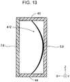
- the arc described above has a horizontal U-shape
- the whole of the liquid storage section 412 is likely to shrink and wrinkle.
- the arc has an S-shape, however, the liquid storage section 412 is likely to shrink from top to bottom, making it difficult for the liquid storage section 412 to wrinkle. Therefore, more ink can be collected in the liquid flow path 412E. This makes it possible to more efficiently reduce the amount of ink remaining in the liquid container.
- the liquid flow path 412E is formed along the direction in which the lower edge 412B of the liquid storage section 412 extends. Therefore, ink that is present in a portion, in the liquid storage section 412, opposite to the liquid supply section 414 can also be led easily to the liquid supply section 414. This makes it possible to more efficiently reduce the amount of remaining ink.
- FIG. 12 indicates preferable relationships of dimensions that the film 450 and case 8 take.
- a plurality of cartridges 4 in which the film 450 and case 8 had different dimensions were prepared.
- the amount of remaining ink was measured when an ink end was detected in the printer 20 and, at that time, the state of the deformed liquid storage section 412 was observed.
- FIG. 12 indicates measurement results and observation results.
- "film length ratio” is the ratio of the sum of the width W of the case 8 and the height H of the case 8 to the length L of the film 450 in the height direction of the case 8.
- the length L of the film 450 in the height direction of the case 8 was measured when the liquid storage section 412 stored no ink and was thereby flat along the Z direction as illustrated in FIG. 8 .
- the length L was measured along the outer surface of the liquid storage section 412 in the Z direction.
- the width W of the case 8 was the dimension of the case 8 along the X direction as illustrated in FIG. 9 .
- the height H of the case 8 was the dimension of the case 8 along the Z direction.
- black indicates that a cartridge 4 in which a black ink was stored was used and "color” indicates that a cartridge 4 in which a color ink was stored was used.
- the horizontal arrangement of "black” and “color” indicates that the liquid storage sections 412 of these inks had the same dimensions but their relevant cases 8 had different dimensions.
- a hyphen (-) in FIG. 12 indicates that measurement or observation was not performed.
- B indicates that the amount of remaining ink was equal to or more than a reference weight equivalent to 1% of the volume of the liquid storage section 412
- A indicates that the amount of remaining ink was less than the reference weight.
- the film length ratios of cartridges 4 for which the amount of remaining ink was less than the standard weight and deformation was in an S-shape were within a range of 0.98 to 1.23, as illustrated in FIG. 12 .
- the dimensions of the case 8 and liquid storage section 412 it is preferable for the dimensions of the case 8 and liquid storage section 412 to have been set so that the film length ratio falls into this range.
- the film 450 is pressed by the case 8 under substantially constant pressure, so the first film 451 can be kept warped as illustrated in FIG. 9 up to the last. This makes it possible to reduce the amount of remaining ink.
- FIG. 15 illustrates the shape of a liquid storage section 412b in a second embodiment.
- the two films 450 constituting the liquid storage section 412 have had the same shape.
- the length of one of the two films 450 is longer than the length of the other film 450.
- the liquid flow path 412E can be easily formed. This makes it possible to reduce the amount of ink remaining in the cartridge 4.
- the film length ratio of the film 450 having a shorter length in the Z direction is preferably within a range of 0.98 to 1.23.
- FIG. 16 illustrates the shape of a liquid storage section 412c in a third embodiment.
- the two films 450 constituting the liquid storage section 412 have had the same shape.
- at least one of the two films 450 opposite to each other has a knob section 500 that holds the film 450 and warps it toward the outside of the liquid storage section 412c.
- the knob section 500 has, for example, a pair of knob members 501 that interpose the film 450 from opposing sides in the Z direction and also has an urging member 502 that urges the pair of knob members 501 in a direction in which they approach each other.
- the liquid flow path 412E can be easily formed.
- the two films 450 constituting the liquid storage section 412c may have the same shape.
- the film 450 having the knob section 500 may be longer in the height direction than the other film 450.
- the position at which the film 450 is held is preferably at a lower portion of the liquid storage section 412c.
- the two films 450 constituting the liquid storage section 412 have had the same shape and had been formed from the same material.
- the stiffness of one of the opposing films 450 is lower than the stiffness of the other film 450.
- the liquid flow path 412E can be easily formed. This makes it possible to reduce the amount of ink remaining in the cartridge 4.
- they can be formed from, for example, different materials.
- the first film 451 and second film 452 are each formed as a multi-layer film
- a difference in stiffness can be made between the first film 451 and the second film 452 by making a difference between their layer structures.
- one of the two films 450 is formed by laminating a polyethylene layer, a nylon layer, an aluminum layer, and a nylon layer in that order from the inside, it is possible to make a difference in stiffness between the two films 450 by, for example, changing the thickness of at least one layer in the other film 450 or providing another layer between any two layers in the other film 450.
- a sheet-like film member may be attached to the surface of one of the two films 450 having the same structure to make a difference in stiffness between the two films 450.
- the two films 450 may have the same length or may have different lengths.
- the liquid flow path 412E can be easily formed.
- droplet refers to a liquid expelled from a liquid ejecting apparatus in one of various states. Droplets in these states include a droplet in a granular state, a tear-like droplet, and a droplet tailing like a string.
- the liquid referred to here only needs to be a material that a liquid ejecting apparatus can consume.
- the liquid may be a material in a state in which the substance is in a liquid phase.
- liquid materials included in liquids are liquid materials having high viscosity or low viscosity, inorganic solvents such as sols, gel water, and the like, organic solvents, solutions, liquid resins, and liquid metals (metallic melts).
- liquids which are in one state of substances, but also solvents in which particles of a functional material composed of pigments, metal particles, or another solid are dissolved, dispersed, or mixed are also included in liquids.
- Typical examples of liquids include liquid crystals and inks described in the above embodiments.
- Inks referred to here include ordinary water-based inks and oil-based inks as well as various liquid compositions such as gel inks and hot melt inks.
- the present disclosure is not limited to aspects implemented as the liquid container and liquid ejecting apparatus described above, but can be implemented as other various aspects including a method of supplying a liquid.
Landscapes
- Engineering & Computer Science (AREA)
- Quality & Reliability (AREA)
- Ink Jet (AREA)
Abstract
Description
- The present application is based on, and claims priority from
JP Application Serial Number 2018-212960, filed November 13, 2018 - The present disclosure relates to a liquid container and a liquid ejecting apparatus.
- In known technologies to increase the efficiency of using an ink in an ink cartridge, an ink path through which the ink passes is formed in an ink pack accommodated in the ink cartridge. In
JP-A-2001-293882 JP-A-2001-328272 - In the technologies described above, however, ink may be left in the ink path formed by the tight-contact preventing member or by press-molding. Therefore, there is a demand for a technology that can reduce the amount of liquid remaining in a liquid container without using a tight-contact preventing member or performing press-molding.
- A first aspect of the present disclosure provides a liquid container from which a liquid can be supplied to a liquid ejecting head in a liquid ejecting apparatus. This liquid container has a liquid storage body that stores the liquid and also has a case that stores the liquid storage body. The liquid storage body has a liquid storage section formed like a bag by joining the edges of opposing films together and also has a liquid supply section that can supply the liquid from the interior of the liquid storage section to its outside. In a state in which the liquid storage section is filled with the liquid and the liquid storage body is installed in the liquid ejecting apparatus, at least part of the upper edge of the liquid storage section and at least part of the lower edge of the liquid storage section are in contact with the case and a first inner surface of the liquid storage section and its second inner surface opposite to the first inner surface are separated from each other. The liquid storage section is structured so that as the liquid is supplied, the first inner surface and second inner surface gradually approach each other and, at the same time, come into contact with each other from top to bottom, forming, at the bottom of the interior of the liquid storage section, a liquid flow path through which the liquid flows from the liquid storage section to the liquid supply section.
- A second aspect of the present disclosure provides a liquid ejecting apparatus. This liquid ejecting apparatus has the liquid container in the above aspect and a liquid ejecting head that ejects the liquid supplied from the liquid container.
-
-
FIG. 1 schematically illustrates the structure of a liquid ejecting system. -
FIG. 2 is a perspective view illustrating the outside shape of a cartridge installation section. -
FIG. 3 is another perspective view illustrating the outside shape of the cartridge installation section. -
FIG. 4 is perspective view illustrating the outside shape of a cartridge. -
FIG. 5 is an exploded perspective view of the cartridge. -
FIG. 6 is a side view of a liquid storage section. -
FIG. 7 is a top view of the liquid storage section. -
FIG. 8 is a front view of the liquid storage section. -
FIG. 9 illustrates a placement of the liquid storage section in a case. -
FIG. 10 illustrates another placement of the liquid storage section in the case. -
FIG. 11 illustrates yet another placement of the liquid storage section in the case. -
FIG. 12 indicates preferable relationships of dimensions that a film and a case take. -
FIG. 13 illustrates an aspect in which the liquid storage section is horizontally U-shaped. -
FIG. 14 illustrates in a state in which the entire liquid storage section wrinkles. -
FIG. 15 illustrates the shape of a liquid storage section in a second embodiment. -
FIG. 16 illustrates the shape of a liquid storage section in a third embodiment. -
FIG. 1 schematically illustrates the structure of aliquid ejecting system 1 in a first embodiment of the present disclosure. InFIG. 1 , the X-axis, Y-axis, and Z-axis, which are three spatial axes orthogonal to one another, are drawn. The arrows of the X-axis, Y-axis, and Z-axis respectively indicate positive directions along the X-axis, Y-axis, and Z-axis. The positive directions along the X-axis, Y-axis, and Z-axis are respectively referred to as the +X direction, +Y direction, and +Z direction. Directions opposite to the directions indicated by the arrows of the X-axis, Y-axis, and Z-axis are negative directions along the X-axis, Y-axis, and Z-axis. The negative directions along the X-axis, Y-axis, and Z-axis are respectively referred to as the -X direction, -Y direction, and -Z direction. When it does not matter whether directions along the X-axis, Y-axis, and Z-axis are positive or negative, these directions are respectively referred to simply as the X-direction, Y-direction, and Z-direction. These are also true for the drawings referred below and the descriptions given below. The directions of the X-axis, Y-axis, and Z-axis indicated in the drawings other thanFIG. 1 match the directions of the X-axis, Y-axis, and Z-axis inFIG. 1 . In this embodiment, the Z axis is an axis along the direction of the force of gravity or the vertical direction and the -Z direction is the direction of the force of gravity or the vertical direction. - The
liquid ejecting system 1 has aprinter 20 as a liquid ejecting apparatus and also has four cartridges denoted 4C, 4M, 4Y, and 4K as liquid containers. Theprinter 20 is an ink jet printer that ejects an ink used as a liquid from arecording head 225 used as a liquid ejecting head. When the fourcartridges reference numeral 4. In a state in which theliquid ejecting system 1 andprinter 20 are in use, the +Z direction is upward in the vertical direction and the -Z direction is downward in the vertical direction. The state in which theliquid ejecting system 1 andprinter 20 are in use refers to a state in which theliquid ejecting system 1 is installed on a horizontal installation surface defined by the X direction and Y direction. - The
printer 20 has amain case 212 shaped like a substantially rectangular box and also has acontroller 230 disposed in themain case 212. Thecontroller 230 controls the printing operation of theprinter 20 and other various operations and transmits and receives signals to and from thecartridges 4. - In the
main case 212, aplaten 213 is disposed so as to be along the X direction, which is the longitudinal direction of themain case 212. Theplaten 213 is a pedestal that supports recoding paper P, which is a target to which ejection is directed. On theplaten 213, the recoding paper P is supplied by a paper feed mechanism (not illustrated) along a sub-scanning direction orthogonal to a main scanning direction. In this embodiment, the main scanning direction is the X direction and the sub-scanning direction is the Y direction. - The
printer 20 further has aguide shaft 214, acarriage 215, adriving pulley 216, a drivenpulley 217, and acarriage motor 218. - The
guide shaft 214 is positioned more on the +Z direction side than is theplaten 213. Theguide shaft 214 is a rod-like member along the main scanning direction. Thecarriage 215 is supported by theguide shaft 214 so as to be movable along theguide shaft 214. - The driving
pulley 216 and drivenpulley 217 are rotatably disposed at positions corresponding to both ends of theguide shaft 214, the positions being more on the -Y direction side than is theguide shaft 214. Thecarriage motor 218 is linked to thedriving pulley 216. Anendless timing belt 219 that supports thecarriage 215 is passed between the drivingpulley 216 and the drivenpulley 217. When driven by thecarriage motor 218, therefore, thecarriage 215 can move bidirectionally in the main scanning direction along theguide shaft 214. Although, in this embodiment, therecording head 225 is structured so that it can move bidirectionally in the main scanning direction, this is not a limitation. For example, therecording head 225 may be a line head that extends along the X direction and the position of which is fixed. - The
printer 20 further has acartridge installation section 6 in which thecartridges 4 are detachably installed. Thecartridge installation section 6 is also referred to as the holder. Thecartridge installation section 6 is disposed inside themain case 212. Themain case 212 is structured so that part of it can be opened and closed. When this openable and closable part is opened, thecartridge 4 can be attached to and detached from thecartridge installation section 6. Although, in this embodiment, thecartridge installation section 6 is disposed inside themain case 212, this is not a limitation. For example, the whole or part of thecartridge installation section 6 may be outside themain case 212. - The
cartridge installation section 6 detachably accommodates the fourcartridges cartridge 4K stores a black ink. Thecartridge 4C stores a cyan ink. Thecartridge 4M stores a magenta ink. Thecartridge 4Y stores a yellow ink. Each type of ink is a pigmented ink that includes pigment particles and a dispersant such as water. Theprinter 20 has four liquid flow paths 223 in correspondence to the fourcartridges relevant cartridge 4 andrecording head 225 communicate with each other. - When installed in the
cartridge installation section 6, thecartridge 4 is coupled to the upstream end of the relevant liquid flow path 223. The downstream end of the liquid flow path 223 is coupled to the upstream end of avalve unit 224 mounted on thecarriage 215. The downstream side of thevalve unit 224 is coupled to therecording head 225 disposed on the lower surface of thecarriage 215. That is, the ink stored in thecartridge 4 passes through the liquid flow path 223 and into therecording head 225. - A home position HP, to which the
recording head 225 is retracted, is provided between thecartridge installation section 6 and theplaten 213. At this home position HP, various types of maintenance processing such as cleaning are performed for therecording head 225 before printing starts. - The
printer 20 further has apressuring mechanism 280 that supplies a pressurized fluid to eachcartridge 4. Thepressuring mechanism 280 is disposed inside themain case 212. Thepressuring mechanism 280 has a pressurizingpump 226, from which pressurized air is supplied as the pressurized fluid, and a plurality offluid flow paths 227, through which the pressurized air is supplied to thecartridges 4. - The pressurizing
pump 226 is coupled to the upstream ends of thefluid flow paths 227. Eachfluid flow path 227 is a tube. Thefluid flow paths 227 branch from adistributor 228 provided at the downstream of the pressurizingpump 226. The downstream end of each branchingfluid flow path 227 is coupled to therelevant cartridge 4. There are fourfluid flow paths 227, which are liquidfluid flow paths cartridges 4. Thecontroller 230 controls the operation of the pressurizingpump 226 to supply the pressurized fluids to thecartridges 4 through thefluid flow paths 227. - Each
fluid flow path 227 allows a flow of pressurized air used to supply the ink stored in therelevant cartridge 4 to therecording head 225. The liquidfluid flow paths cartridges 4. Thus, a liquid storage section stored in eachcartridge 4 is pressed. When the liquid storage section is pressed, the ink passes through the liquid flow path 223 and into therecording head 225. - Although, in this embodiment, a
single pressurizing pump 226 common to the liquidfluid flow paths pumps 226 may be provided in correspondence to the liquidfluid flow paths -
FIG. 2 is a perspective view illustrating the outside shape of thecartridge installation section 6.FIG. 3 is another perspective view illustrating the outside shape of thecartridge installation section 6. InFIG. 3 , part of the structure of thecartridge installation section 6 is omitted so that the interior of thecartridge installation section 6 can be viewed. Eachcartridge 4 is installed in thecartridge installation section 6 in the -Y direction and is detached from thecartridge installation section 6 in the +Y direction. - As illustrated in
FIG. 2 , acartridge storage chamber 61 in which thecartridges 4 are accommodated is formed in thecartridge installation section 6 from six wall portions described later. Thecartridge storage chamber 61 is shaped like a substantially rectangular parallelepiped. Thecartridge storage chamber 61 includes four portions in each of which one of the fourcartridges FIG. 3 , the portion in which thecartridge 4K is accommodated is referred to as theslot 61K, the portion in which thecartridge 4C is accommodated is referred to as theslot 61C, the portion in which thecartridge 4M is accommodated is referred to as theslot 61M, and the portion in which thecartridge 4Y is accommodated is referred to as theslot 61Y. - The
cartridge installation section 6 has an apparatus-sidefront wall portion 62, a first apparatus-sideside wall portion 63, and a second apparatus-sideside wall portion 64. Thecartridge installation section 6 also has a third apparatus-sideside wall portion 65 and a fourth apparatus-sideside wall portion 66. Thecartridge storage chamber 61 is defined by these fivewall portions wall portions cartridge storage chamber 61 has anopening 61A at a position opposite to the apparatus-sidefront wall portion 62. - As illustrated in
FIGs. 2 and3 , the apparatus-sidefront wall portion 62 is positioned more on the -Y direction side than is thecartridge storage chamber 61. When theprinter 20 is in use, the apparatus-sidefront wall portion 62 is a perpendicular wall portion. - As illustrated in
FIG. 3 , thecartridge installation section 6 has aliquid supply mechanism 640 and a liquidsupply pressurizing section 67. Theliquid supply mechanism 640 and liquidsupply pressurizing section 67 are disposed in the apparatus-sidefront wall portion 62. Oneliquid supply mechanism 640 and one liquidsupply pressurizing section 67 are provided for each of theslots cartridges - The
liquid supply mechanism 640 has acover member 650 and aliquid entrance 643. Theliquid entrance 643 is used to allow the ink in thecartridge 4 to flow into theprinter 20. Theliquid entrance 643 is like a tube having a central axis extending along the Y direction. Theliquid entrance 643 is coupled to thecartridge 4. - The
cover member 650 encloses the periphery of theliquid entrance 643 about the central axis of theliquid entrance 643. Thecover member 650 reduces the possibility that ink scatters to the outside when thecartridge 4 is attached or detached. Thecover member 650 is urged in the +Y direction by an urging member (not illustrated), such as a coil spring, included in theliquid supply mechanism 640. Thecover member 650 is structured so as to be movable along the Y direction. In the attachment of thecartridge 4, thecartridge 4 abuts thecover member 650. Then, thecover member 650 moves in the -Y direction against the urging force of the urging member. Thus, the end of theliquid entrance 643 on the +Y direction side protrudes from thecover member 650 in the +Y direction and is coupled to thecartridge 4. - The liquid
supply pressurizing section 67 is a tubular member through which pressurized air flows, the pressurized air being a pressurized fluid that supplies the ink in thecartridge 4 to therecording head 225. The liquidsupply pressurizing section 67 is coupled to the downstream end of the liquidfluid flow path cartridge 4 installed, the liquidsupply pressurizing section 67 is coupled to thecartridge 4. A tubular seal member is provided on the inner circumferential surface of the liquidsupply pressurizing section 67. This seal member is formed from, for example, rubber. -
FIG. 4 is perspective view illustrating the outside shape of thecartridge 4.FIG. 5 is an exploded perspective view of thecartridge 4. Thecartridge 4 is a liquid container from which an ink can be supplied to therecording head 225 in theprinter 20 as a liquid. InFIGs. 4 and5 , the X axis, Y axis, and Z axis are indicated in a state in which thecartridges 4 are installed in theprinter 20. In the subsequent drawings as well, the X axis, Y axis, and Z axis are indicated as necessary in a state in which thecartridge 4K is installed in theprinter 20. InFIGs. 4 and5 , of thecartridges cartridge 4C is illustrated as the structure of thecartridge 4. In this embodiment, the structures of the fourcartridges cartridge 4K has a larger width in the X direction than theother cartridges - The outside shape of the
cartridge 4 is a substantially rectangular parallelepiped as illustrated inFIG. 4 . Of the dimensions of thecartridge 4, the dimension in the Y direction is smallest, followed by the dimension in the Z direction and the dimension in the X direction in that order. The X direction is also referred to as the width direction of thecartridge 4, and the Z direction is also referred to as the height direction of thecartridge 4. Thecartridge 4 has acase 8 forming an outer shell. Thecase 8 is a cabinet formed by being molded from a polypropylene resin, polystyrene resin, or other synthetic resin. - The
cartridge 4 has afront wall 42, arear wall 47, atop wall 43, abottom wall 44, afirst side wall 45, and asecond side wall 46. Thecartridge 4 further has a secondfront wall 41 positioned closer to therear wall 47 than is thefront wall 42. The secondfront wall 41 andfront wall 42 face in the -Y direction, which is the installation direction. - The
front wall 42 andrear wall 47 are opposite to each other in the Y direction. Thefront wall 42 is positioned on the -Y direction side, and therear wall 47 is positioned on the +Y direction side. Thetop wall 43 andbottom wall 44 cross thefront wall 42 andrear wall 47, and are opposite to each other in the Z direction. Thetop wall 43 is positioned on the +Z direction side, and thebottom wall 44 is positioned on the -Z direction side. Thefirst side wall 45 andsecond side wall 46 cross thefront wall 42,rear wall 47,top wall 43, andbottom wall 44, and are opposite to each other in the X direction. Thefirst side wall 45 is positioned on the +X direction side, and thesecond side wall 46 is positioned on the -X direction side. In this specification, when two walls cross each other, this implies any one of a state in which the two walls actually cross each other, a state in which an extension of one of the two walls crosses the other wall, and a state in which extensions of the two walls cross each other. - It can also be said that the
front wall 42 is formed at aprotrusion 48, which protrudes from the secondfront wall 41 in the -Y direction. The shape of thefront wall 42 is substantially a rectangle having a larger dimension in the Z direction than in the X direction. With thecartridge 4 installed, thefront wall 42 faces the apparatus-sidefront wall portion 62 illustrated inFIG. 3 . - The
cartridge 4 has aliquid storage body 410 that stores an ink and also has thecase 8 in which theliquid storage body 410 is placed, as illustrated inFIG. 5 . The state in which thecartridge 4 is installed in theprinter 20 is also a state in which theliquid storage body 410 accommodated in thecartridge 4 is installed in theprinter 20. Thecase 8 is composed of afirst case 5 and a second case 7. Thefirst case 5 and second case 7 are formed by being molded from a synthetic resin. - The
first case 5 has a concave shape having an opening in the +X direction. Thefirst case 5 mainly forms thefront wall 42,top wall 43,bottom wall 44,second side wall 46,rear wall 47, secondfront wall 41, andprotrusion 48. Aseat member 430 is joined to anend face 59 that defines the opening of thefirst case 5. - The
seat member 430 is formed from a thin film. Theseat member 430 is airtightly joined to theend face 59 that defines the opening of thefirst case 5 so as to seal the opening. When theseat member 430 is airtightly joined to theend face 59, aninner chamber 440 in which aliquid storage section 412 is accommodated is defined. Thisinner chamber 440 receives a supply of pressurized air that passes through thefluid flow path 227. In theinner chamber 440, the supplied pressurized air presses theliquid storage section 412. Thus, the ink stored in theliquid storage section 412 is pressurized. When the ink in theliquid storage section 412 is pressurized with thecartridge 4 installed, the ink stored in theliquid storage section 412 is supplied to theprinter 20. That is, theinner chamber 440 also functions as a pressurizing chamber that pressurizes the ink in theliquid storage section 412 to supply the ink in theliquid storage section 412 to theprinter 20. - The second case 7 is attached to the
first case 5 so as to cover theseat member 430. The second case 7 mainly forms thefirst side wall 45. Theliquid storage body 410 andseat member 430 are protected by thefirst case 5 and second case 7, suppressing theliquid storage body 410 andseat member 430 from being damaged. - The
liquid storage body 410 has theliquid storage section 412 and aliquid supply section 414. Theliquid storage section 412 stores an ink. Theliquid storage section 412 is formed from a flexible film. Theliquid storage section 412 is in the form of a bag. The volume of theliquid storage section 412 is reduced as the ink in theliquid storage section 412 is consumed. The whole of theliquid storage section 412 may not be formed from a flexible member. At least part of theliquid storage section 412 may be formed from a flexible member. - The
liquid supply section 414 can supply an ink from the interior of theliquid storage section 412 to its outside. Theliquid supply section 414 allows the ink stored in theliquid storage section 412, which functions as a liquid supply source, to flow toward theprinter 20. When theliquid entrance 643 in a tubular shape is inserted into theliquid supply section 414 with thecartridge 4 installed, theliquid supply section 414 andliquid entrance 643 are coupled together. The ink in theliquid storage section 412 flows through theliquid supply section 414 andliquid entrance 643 and into therecording head 225 in theprinter 20. Theliquid supply section 414 has a central axis CL. The central axis CL extends in parallel to the -Y direction, in which thecartridge 4 is installed. Theliquid supply section 414 internally has a tubular member through which an ink can flow. Theliquid supply section 414 is coupled to the end of theliquid storage section 412 in the -Y direction. A valve mechanism is provided in theliquid supply section 414. This valve mechanism is opened when theliquid entrance 643 is coupled to theliquid supply section 414. -
FIG. 6 is a side view of theliquid storage section 412.FIG. 7 is a top view of theliquid storage section 412.FIG. 8 is a front view of theliquid storage section 412. Theliquid storage section 412 is formed by joining the ends of two films, a first film 451 and a second film 452, which are opposite to each other in the X direction, by thermal fusion or the like. In this embodiment, the first film 451 and second film 452 have the same shape and are formed from the same material. The width MW of a portion over which the first film 451 and second film 452 are joined together is 4.5 mm. In the description below, when the first film 451 and second film 452 are referred to without a distinction, they will be referred to as a film 450. Theliquid storage section 412 has an elongated shape having a larger dimension in the Y direction than in the Z direction. Theliquid supply section 414 is attached at the center of an end of theliquid storage section 412, the center being in the Z direction, the end being in the -Y direction, so that theliquid supply section 414 is interposed between the first film 451 and the second film 452. In this embodiment, theliquid storage section 412 has a substantially octagonal shape having a side along thetop wall 43 and a side along thebottom wall 44. In other words, theliquid storage section 412 has a shape resulting from cutting the four corners of a quadrangular shape. This shape restrains the four corners of theliquid storage section 412 from protruding in the X direction when theliquid storage section 412 is filled with an ink. With theliquid storage section 412 accommodated in thecase 8, therefore, it is possible to restrain theseat member 430 from being damaged by a corner of theliquid storage section 412. The shape of theliquid storage section 412 is not limited to an octagon if theliquid storage section 412 has a side along thetop wall 43 and a side along thebottom wall 44. Theliquid storage section 412 may have another polygonal shape such as a rectangular or hexagonal shape. Sides other than the side along thetop wall 43 and the side along thebottom wall 44 may be curved lines. -
FIG. 9 illustrates a placement of theliquid storage section 412 in thecase 8. Specifically,FIG. 9 schematically illustrates an end face of thecartridge 4 in a state in which theliquid storage section 412 is filled with an ink and theliquid storage body 410 is installed in theprinter 20. The end face in this schematic drawing is the end face taken along line IX-IX inFIG. 4 . InFIG. 9 and later drawings, theseat member 430 is appropriately omitted to simply the drawings. As illustrated inFIG. 9 , in a state in which theliquid storage section 412 is filled with an ink and theliquid storage body 410 is installed in theprinter 20, at least part of theupper edge 412A of theliquid storage section 412 and at least part of thelower edge 412B of theliquid storage section 412 are in contact with thecase 8. In this embodiment, theliquid storage section 412 is substantially octagonal as illustrated inFIG. 6 . In this embodiment, therefore, the whole of theupper edge 412A of theliquid storage section 412 is not in contact with thecase 8, but only the central portion of theupper edge 412A of theliquid storage section 412 in the Y direction is in contact withcase 8. Similarly, the whole of thelower edge 412B of theliquid storage section 412 is not in contact with thecase 8, but only the central portion of thelower edge 412B of theliquid storage section 412 in the Y direction is in contact withcase 8. When, for example, theliquid storage section 412 is rectangular, the whole of theupper edge 412A of theliquid storage section 412 and the whole of thelower edge 412B of theliquid storage section 412 are in contact with thecase 8. On the inner surface of thetop wall 43, theupper edge 412A of theliquid storage section 412 comes into contact with thecase 8. On the inner surface of thebottom wall 44, thelower edge 412B of theliquid storage section 412 comes into contact with thecase 8. In this embodiment, theupper edge 412A andlower edge 412B of theliquid storage section 412 are in contact with thecase 8 in a state in which they are curved so as to face in the +X direction toward which thefirst case 5 is open. With theliquid storage section 412 filled with an ink, a firstinner surface 412C of theliquid storage section 412 and its secondinner surface 412D opposite to the firstinner surface 412C are separated from each other. The firstinner surface 412C is the inner surface of the first film 451 disposed on the +X direction side, and the secondinner surface 412D is the inner surface of the second film 452 disposed on the -X direction side. With theliquid storage section 412 filled with an ink, the firstinner surface 412C is curved so as to be convex in the +X direction toward which thefirst case 5 is open. The secondinner surface 412D is curved so as to be convex toward thesecond side wall 46, which is a wall of thefirst case 5 on the -X direction side. The extent to which the firstinner surface 412C is convex in the +X direction is larger than the extent to which the secondinner surface 412D is convex in the -X direction. -
FIG. 10 illustrates another placement of theliquid storage section 412 in thecase 8. InFIG. 10 , the ink in theliquid storage section 412 has been consumed to a certain extent. As the ink in theliquid storage section 412 is supplied to theprinter 20 through theliquid supply section 414, the secondinner surface 412D gradually approaches the firstinner surface 412C and, at the same time, comes into contact with the firstinner surface 412C from top to bottom. The reason why the firstinner surface 412C and secondinner surface 412D come into contact with each other from top to bottom, the ink is likely to remain at the bottom of theliquid storage section 412 due to the force of gravity of the ink. In this embodiment, the secondinner surface 412D approaches the firstinner surface 412C along with the supply of the ink while drawing an arc so as to follow the firstinner surface 412C. This is because both theupper edge 412A andlower edge 412B of theliquid storage section 412 are bent so as to face in a direction toward which the firstinner surface 412C is curved and the curved firstinner surface 412C is thereby pressed inwardly from thetop wall 43 andbottom wall 44 of thecase 8, so the secondinner surface 412D is more likely to be deformed toward the firstinner surface 412C than is the firstinner surface 412C is deformed toward the secondinner surface 412D. The shape of the arc drawn by the secondinner surface 412D is a substantially S-shape formed by the secondinner surface 412D and thelower edge 412B of theliquid storage section 412 when theliquid storage section 412 is viewed from the +Y direction toward the -Y direction. When the secondinner surface 412D approaches the firstinner surface 412C and, at the same time, comes into contact with the firstinner surface 412C from top to bottom, aliquid flow path 412E is formed through which the ink in theliquid storage section 412 flows toward theliquid supply section 414 is formed at the bottom of the interior of theliquid storage section 412. The bottom of the interior of theliquid storage section 412 refers to a portion lower than the center of theliquid storage section 412 in its height direction. Preferably, that portion is immediately above thelower edge 412B. In this embodiment, theliquid flow path 412E is formed along the direction in which thelower edge 412B of theliquid storage section 412 extends. InFIG. 6 , the direction in which theliquid flow path 412E extends is indicated. The direction in which theliquid flow path 412E extends is substantially the Y direction. -
FIG. 11 illustrates another placement of theliquid storage section 412 in thecase 8. As the ink in theliquid storage section 412 is supplied to the outside of theliquid storage section 412 through theliquid flow path 412E, the volume of theliquid flow path 412E illustrated inFIG. 10 is gradually reduced. Then, as illustrated inFIG. 11 , the firstinner surface 412C and secondinner surface 412D of theliquid storage section 412 come into tight contact with each other and thereby theliquid flow path 412E disappears. Almost all of the ink in theliquid storage section 412 andliquid flow path 412E is discharged to the outside. - In the first embodiment described so far, the second
inner surface 412D of theliquid storage section 412 gradually approach its firstinner surface 412C as the supply of the ink and, at the same time, comes into contact with the firstinner surface 412C from top to bottom. As a result, theliquid flow path 412E is formed at the bottom of the interior of theliquid storage section 412. When the ink is further supplied, the firstinner surface 412C and secondinner surface 412D come into tight contact with each other, reducing the volume of theliquid flow path 412E. This makes it possible to reduce the amount of ink remaining in thecartridge 4. - In this embodiment, since the
liquid flow path 412E is formed as the secondinner surface 412D of theliquid storage section 412 comes into contact with its firstinner surface 412C from top to bottom, there is no need to provide, in theliquid storage section 412, a special member to form theliquid flow path 412E or to add, to theliquid storage section 412, a special process to form theliquid flow path 412E. This makes it possible to reduce the manufacturing cost of thecartridge 4. - In this embodiment, the second
inner surface 412D of theliquid storage section 412 approaches its firstinner surface 412C along the supply of the ink while drawing an arc so as to follow the firstinner surface 412C. Therefore, it is possible to restrains wrinkles from being created in theliquid storage section 412, so more ink can be collected in theliquid flow path 412E. This makes it possible to more efficiently reduce the amount of ink remaining in thecartridge 4. - In this embodiment, the shape of the arc described above is an S-shape formed by the second
inner surface 412D and thelower edge 412B of theliquid storage section 412. When, for example, the arc described above has a horizontal U-shape, the whole of theliquid storage section 412 is likely to shrink and wrinkle. Since, in this embodiment, the arc has an S-shape, however, theliquid storage section 412 is likely to shrink from top to bottom, making it difficult for theliquid storage section 412 to wrinkle. Therefore, more ink can be collected in theliquid flow path 412E. This makes it possible to more efficiently reduce the amount of ink remaining in the liquid container. - In this embodiment, the
liquid flow path 412E is formed along the direction in which thelower edge 412B of theliquid storage section 412 extends. Therefore, ink that is present in a portion, in theliquid storage section 412, opposite to theliquid supply section 414 can also be led easily to theliquid supply section 414. This makes it possible to more efficiently reduce the amount of remaining ink. -
FIG. 12 indicates preferable relationships of dimensions that the film 450 andcase 8 take. A plurality ofcartridges 4 in which the film 450 andcase 8 had different dimensions were prepared. For eachcartridge 4, the amount of remaining ink was measured when an ink end was detected in theprinter 20 and, at that time, the state of the deformedliquid storage section 412 was observed.FIG. 12 indicates measurement results and observation results. InFIG. 12 , "film length ratio" is the ratio of the sum of the width W of thecase 8 and the height H of thecase 8 to the length L of the film 450 in the height direction of thecase 8. The length L of the film 450 in the height direction of thecase 8 was measured when theliquid storage section 412 stored no ink and was thereby flat along the Z direction as illustrated inFIG. 8 . That is, the length L was measured along the outer surface of theliquid storage section 412 in the Z direction. The width W of thecase 8 was the dimension of thecase 8 along the X direction as illustrated inFIG. 9 . The height H of thecase 8 was the dimension of thecase 8 along the Z direction. - In
FIG. 12 , "black" indicates that acartridge 4 in which a black ink was stored was used and "color" indicates that acartridge 4 in which a color ink was stored was used. The horizontal arrangement of "black" and "color" indicates that theliquid storage sections 412 of these inks had the same dimensions but theirrelevant cases 8 had different dimensions. A hyphen (-) inFIG. 12 indicates that measurement or observation was not performed. In the measurement results of the amount of remaining ink, B indicates that the amount of remaining ink was equal to or more than a reference weight equivalent to 1% of the volume of theliquid storage section 412, and A indicates that the amount of remaining ink was less than the reference weight. - In the observation results of the deformed state in
FIG. 12 , a hyphen (-) indicates that observation was not performed, "U-shape" indicates that theliquid storage section 412 was deformed into a horizontal U-shape as illustrated inFIG. 13 , "S-shape" indicates that theliquid storage section 412 was deformed as illustrated inFIG. 11 , as assumed in this embodiment, and "S-shape and wrinkles" indicates a state in which part of theliquid storage section 412 was deformed into an S-shape but wrinkles were formed as a whole as illustrated inFIG. 14 . With thecartridges 4 in which theliquid storage section 412 was classified as "U-shape", the upper and lower edges of theliquid storage section 412 respectively abutted thetop wall 43 andbottom wall 44 of thecase 8 because the length L of theliquid storage section 412 in the height direction was short. As a result, wrinkles were formed in theliquid storage section 412, so ink equal to or more than a reference remaining amount was left. With thecartridges 4 in which theliquid storage section 412 was classified as "S-shape and wrinkles ", the length L of theliquid storage section 412 in the height direction was too long for theliquid storage section 412 to fit to the interior of thecase 8 and theliquid storage section 412 could not be completely stretched in the height direction. As a result, many wrinkles were formed in theliquid storage section 412, so ink equal to or more than the reference remaining amount was left. - Of the
cartridges 4 in black and thecartridges 4 in color, the film length ratios ofcartridges 4 for which the amount of remaining ink was less than the standard weight and deformation was in an S-shape were within a range of 0.98 to 1.23, as illustrated inFIG. 12 . In this embodiment, therefore, it is preferable for the dimensions of thecase 8 andliquid storage section 412 to have been set so that the film length ratio falls into this range. When the film length ratio is within this range, the film 450 is pressed by thecase 8 under substantially constant pressure, so the first film 451 can be kept warped as illustrated inFIG. 9 up to the last. This makes it possible to reduce the amount of remaining ink. -
FIG. 15 illustrates the shape of aliquid storage section 412b in a second embodiment. In the first embodiment, the two films 450 constituting theliquid storage section 412 have had the same shape. In the second embodiment, however, the length of one of the two films 450, the length being along the surface in the Z direction, is longer than the length of the other film 450. In this aspect, since either film 450 has an extra portion caused by the different lengths, theliquid flow path 412E can be easily formed. This makes it possible to reduce the amount of ink remaining in thecartridge 4. In this embodiment, the film length ratio of the film 450 having a shorter length in the Z direction is preferably within a range of 0.98 to 1.23. -
FIG. 16 illustrates the shape of aliquid storage section 412c in a third embodiment. In the first embodiment, the two films 450 constituting theliquid storage section 412 have had the same shape. In the third embodiment, however, at least one of the two films 450 opposite to each other has aknob section 500 that holds the film 450 and warps it toward the outside of theliquid storage section 412c. Theknob section 500 has, for example, a pair ofknob members 501 that interpose the film 450 from opposing sides in the Z direction and also has an urgingmember 502 that urges the pair ofknob members 501 in a direction in which they approach each other. In this aspect, when the film 450 is held by theknob section 500, theliquid flow path 412E can be easily formed. This makes it possible to reduce the amount of ink remaining in thecartridge 4. The two films 450 constituting theliquid storage section 412c may have the same shape. Alternatively, the film 450 having theknob section 500 may be longer in the height direction than the other film 450. The position at which the film 450 is held is preferably at a lower portion of theliquid storage section 412c. - In the first embodiment, the two films 450 constituting the
liquid storage section 412 have had the same shape and had been formed from the same material. In a fourth embodiment, however, the stiffness of one of the opposing films 450 is lower than the stiffness of the other film 450. In this aspect, by use of the film 450 that has low stiffness and is thereby more easily deformed, theliquid flow path 412E can be easily formed. This makes it possible to reduce the amount of ink remaining in thecartridge 4. To make a difference in stiffness between the two films 450, they can be formed from, for example, different materials. When, for example, the first film 451 and second film 452 are each formed as a multi-layer film, a difference in stiffness can be made between the first film 451 and the second film 452 by making a difference between their layer structures. When, for example, one of the two films 450 is formed by laminating a polyethylene layer, a nylon layer, an aluminum layer, and a nylon layer in that order from the inside, it is possible to make a difference in stiffness between the two films 450 by, for example, changing the thickness of at least one layer in the other film 450 or providing another layer between any two layers in the other film 450. Alternatively, a sheet-like film member may be attached to the surface of one of the two films 450 having the same structure to make a difference in stiffness between the two films 450. In the height direction, the two films 450 may have the same length or may have different lengths. When, for example, the film 450, of the two films 450, that has lower stiffness is made longer in the height direction, theliquid flow path 412E can be easily formed. -
- (E-1) In the above embodiments, the
liquid storage section 412 has been formed like a bag by joining the edges of two films 450 together. However, theliquid storage section 412 may be formed by folding a single film and by joining the edges, other than the folded edge, of the film. It is preferable for the folded edge to be opposite to an edge to which theliquid supply section 414 is attached. - (E-2) In the above embodiments, an uneven portion may be formed on the inner surface of at least one of the two films 450 constituting the
liquid storage section 412. In this aspect, the firstinner surface 412C and secondinner surface 412D are not easily come into tight contact with each other, suppressing winkles. This makes it possible to reduce the amount of remaining ink. The uneven portion can be formed by, for example, press molding. - (E-3) In the above embodiments, the lower portion of the surface of one of the films 450 constituting the
liquid storage section 412 may be bonded to the inner surface of thecase 8 orseat member 430. Then, theliquid flow path 412E can be easily formed. This makes it possible to efficiently reduce the amount of remaining ink. - (E-4) In the above embodiments, the second
inner surface 412D of theliquid storage section 412 has approached its firstinner surface 412C along with the supply of ink while drawing an arc so as to follow the firstinner surface 412C. However, the firstinner surface 412C may approach the secondinner surface 412D while drawing an arc so as to follow the secondinner surface 412D. Also, since the secondinner surface 412D or firstinner surface 412C only needs to come into contact with its counterpart from top to bottom, the firstinner surface 412C or secondinner surface 412D may approach the counterpart so as to draw a straight line. - (E-5) In the above embodiments, the
liquid flow path 412E has been formed along the direction in which thelower edge 412B of theliquid storage section 412 extends. However, for example, theliquid flow path 412E may be formed at the lower portion of the interior of theliquid storage section 412 in a diagonal direction or may be formed in a curved shape so as to draw an arc. - (E-6) In the above embodiments, four types of
cartridges 4 have been installed in theprinter 20. However, theprinter 20 may be structured so that one to three types or five or more types ofcartridges 4 can be installed. - (E-7) The present disclosure is not limited to printers and their cartridges, but can also be applied to arbitrary liquid ejecting apparatuses that consume a liquid other than inks and to liquid containers used in these liquid ejecting apparatuses. For example, the present disclosure can be applied as a liquid container used in various types of liquid ejecting apparatuses as described below.
- (1) Image recording apparatuses such as facsimile machines
- (2) Color material ejecting apparatuses used to manufacture color filters for use in image display apparatuses such as liquid crystal displays
- (3) Electrode material ejecting apparatuses used to form electrodes in electroluminescence (EL) displays, field emission displays (FEDs), and the like
- (4) Liquid electing apparatuses that eject a liquid including bio-organic substances used in the manufacturing of biochips
- (5) Sample ejecting apparatuses used as precise pipettes
- (6) Lubricant ejecting apparatuses
- (7) Resin solution ejecting apparatuses
- (8) Liquid ejecting apparatuses that eject a lubricant to a clock, a camera, or another precision machine at a particular point
- (9) Liquid ejecting apparatuses that eject a transparent resin solution such as an ultraviolet curable resin solution to a substrate to form a minute hemispherical lens (optical lens) or the like used in an optical communication element or the like
- (10) Liquid ejecting apparatuses that eject an acidic or alkaline etching solution to etch a substrate or the like
- (11) Liquid ejecting apparatuses having a liquid ejecting head that expels a very small amount of any other droplets
- The term "droplet" refers to a liquid expelled from a liquid ejecting apparatus in one of various states. Droplets in these states include a droplet in a granular state, a tear-like droplet, and a droplet tailing like a string. The liquid referred to here only needs to be a material that a liquid ejecting apparatus can consume. For example, the liquid may be a material in a state in which the substance is in a liquid phase. Examples of liquid materials included in liquids are liquid materials having high viscosity or low viscosity, inorganic solvents such as sols, gel water, and the like, organic solvents, solutions, liquid resins, and liquid metals (metallic melts). Not only liquids, which are in one state of substances, but also solvents in which particles of a functional material composed of pigments, metal particles, or another solid are dissolved, dispersed, or mixed are also included in liquids. Typical examples of liquids include liquid crystals and inks described in the above embodiments. Inks referred to here include ordinary water-based inks and oil-based inks as well as various liquid compositions such as gel inks and hot melt inks.
- The present disclosure is not limited to the embodiments described above; the present disclosure can be implemented in various structures without departing from the intended scope of the present disclosure. For example, technical features, in the above embodiments, corresponding to technical features in the aspects described below can be appropriately replaced or combined to solve part or all of the problems described above or achieve part or all of the effects described above. When these technical features are not described in this specification as being essential, the technical features can be appropriately deleted.
- (1) A first aspect of the present disclosure provides a liquid container from which a liquid can be supplied to a liquid ejecting head in a liquid ejecting apparatus. This liquid container has a liquid storage body that stores the liquid and also has a case that stores the liquid storage body. The liquid storage body has a liquid storage section formed like a bag by joining the edges of opposing films together and also has a liquid supply section that can supply the liquid from the interior of the liquid storage section to its outside. In a state in which the liquid storage section is filled with the liquid and the liquid storage body is installed in the liquid ejecting apparatus, at least part of the upper edge of the liquid storage section and at least part of the lower edge of the liquid storage section are in contact with the case and a first inner surface of the liquid storage section and its second inner surface opposite to the first inner surface are separated from each other. The liquid storage section is structured so that as the liquid is supplied, the first inner surface and second inner surface gradually approach each other and, at the same time, come into contact with each other from top to bottom, forming, at the bottom of the interior of the liquid storage section, a liquid flow path through which the liquid flows from the liquid storage section to the liquid supply section.
With the liquid container in this aspect, as the liquid is supplied, the first inner surface and second inner surface of the liquid storage section gradually approach each other and, at the same time, come into contact with each other from top to bottom, so a liquid flow path is formed at the bottom of the interior of the liquid storage section. When the liquid is further supplied, the first inner surface and second inner surface come into tight contact with each other and the volume of the liquid flow path is thereby reduced. This makes it possible to reduce the amount of liquid remaining in the liquid container. - (2) In the liquid container in the above aspect, the second inner surface may approach the first inner surface along with the supply of the liquid while drawing an arc so as to follow the first inner surface. In this aspect, it is possible to restrain wrinkles from being created in the liquid storage section, so more liquid can be collected in the liquid flow path. This makes it possible to more efficiently reduce the amount of ink remaining in the liquid container.
- (3) In the liquid container in the above aspect, the shape of the arc may be an S-shape formed by the second inner surface and the lower edge of the liquid storage section. In this aspect, the liquid storage section is likely to shrink from top to bottom, making it difficult for the liquid storage section to wrinkle. Therefore, more liquid can be collected in the liquid flow path. This makes is possible to more efficiently reduce the amount of liquid remaining in the liquid container.
- (4) In the liquid container in the above aspect, the liquid flow path may be formed along the direction in which the lower edge of the liquid storage section extends. In this aspect, liquid that is present in a portion, in the liquid storage section, opposite to the liquid supply section can also be led easily to the liquid supply section. This makes it possible to more efficiently reduce the amount of remaining liquid.
- (5) In the liquid container in the above aspect, the ratio of the sum of the width of the case and the height of the case to the length of the film in the height direction of the case may be within a range of 0.98 to 1.23. In this aspect, the film can be kept warped in the case. This makes it possible to more efficiently reduce the amount of liquid remaining in the liquid container.
- (6) In the liquid container in the above aspect, the length of one of the opposing films, the length being in the height direction of the case, may be longer than the length of the other film, the length being in the height direction of the case. In this aspect, since either film has an extra portion caused by the different lengths, a liquid flow path can be easily formed. This makes it possible to more efficiently reduce the amount of ink remaining in the liquid container.
- (7) In the liquid container in the above aspect, the stiffness of one of the opposing films is lower than the stiffness of the other film. In this aspect, by use of the film that has low stiffness and is thereby more easily deformed, the liquid flow path can be easily formed. This makes it possible to more efficiently reduce the amount of ink remaining in the liquid container.
- (8) In the liquid container in the above aspect, at least one of the opposing films may have a knob section that holds the film and warps it toward the outside of the liquid storage section. In this aspect, the use of the knob section enables the liquid flow path to be easily formed. This makes it possible to more efficiently reduce the amount of ink remaining in the liquid container.
- (9) A second aspect of the present disclosure provides a liquid ejecting apparatus. This liquid ejecting apparatus has the liquid container in any one of the liquid containers described in the above embodiments and also has a liquid ejecting head that ejects the liquid supplied from the liquid container. The liquid ejecting apparatus in this aspect can reduce the amount of ink remaining in the liquid container.
- The present disclosure is not limited to aspects implemented as the liquid container and liquid ejecting apparatus described above, but can be implemented as other various aspects including a method of supplying a liquid.
Claims (9)
- A liquid container from which a liquid is capable of being supplied to a liquid ejecting head in a liquid ejecting apparatus, the liquid container comprising:a liquid storage body that stores the liquid; anda case that stores the liquid storage body; whereinthe liquid storage body hasa liquid storage section formed like a bag by joining edges of opposing films together, anda liquid supply section configured to supply the liquid from an interior of the liquid storage section to an outside of the liquid storage section,in a state in which the liquid storage section is filled with the liquid and the liquid storage body is installed in the liquid ejecting apparatus, at least part of an upper edge of the liquid storage section and at least part of a lower edge of the liquid storage section are in contact with the case and a first inner surface of the liquid storage section and a second inner surface of the liquid storage section, the second inner surface being opposite to the first inner surface, are mutually separated, andthe liquid storage section is structured so that as the liquid is supplied, the first inner surface and the second inner surface gradually come close together and, at the same time, come into mutual contact from top to bottom, forming, at a bottom of the interior of the liquid storage section, a liquid flow path through which the liquid flows from the liquid storage section to the liquid supply section.
- The liquid container according to claim 1, wherein the second inner surface approaches the first inner surface along with supply of the liquid while drawing an arc so as to follow the first inner surface.
- The liquid container according to claim 2, wherein a shape of the arc is an S-shape formed by the second inner surface and a lower edge of the liquid storage section.
- The liquid container according to any one of the preceding claims, wherein the liquid flow path is formed along a direction in which the lower edge of the liquid storage section extends.
- The liquid container according to any one of the preceding claims, wherein a ratio of a sum of a width of the case and a height of the case to a length of the film in a height direction of the case is within a range of 0.98 to 1.23.
- The liquid container according to any one of the preceding claims, wherein a length of one of the opposing films, the length being in a height direction of the case, is longer than a length of another of the opposing films, the length being in the height direction of the case.
- The liquid container according to any one of the preceding claims, wherein stiffness of one of the opposing films is lower than stiffness of another of the opposing films.
- The liquid container according to any one of the preceding claims, wherein at least one of the opposing films has a knob section that holds the film and warps the film toward the outside of the liquid storage section.
- A liquid ejecting apparatus comprising:the liquid container in any one of the preceding claims; anda liquid ejecting head that ejects the liquid supplied from the liquid container.
Applications Claiming Priority (1)
| Application Number | Priority Date | Filing Date | Title |
|---|---|---|---|
| JP2018212960A JP7155906B2 (en) | 2018-11-13 | 2018-11-13 | liquid container and liquid injection device |
Publications (2)
| Publication Number | Publication Date |
|---|---|
| EP3653389A1 true EP3653389A1 (en) | 2020-05-20 |
| EP3653389B1 EP3653389B1 (en) | 2022-05-04 |
Family
ID=68531421
Family Applications (1)
| Application Number | Title | Priority Date | Filing Date |
|---|---|---|---|
| EP19208268.3A Active EP3653389B1 (en) | 2018-11-13 | 2019-11-11 | Liquid container and liquid ejecting apparatus |
Country Status (4)
| Country | Link |
|---|---|
| US (1) | US10981391B2 (en) |
| EP (1) | EP3653389B1 (en) |
| JP (1) | JP7155906B2 (en) |
| CN (1) | CN111169173B (en) |
Citations (8)
| Publication number | Priority date | Publication date | Assignee | Title |
|---|---|---|---|---|
| DE3401071A1 (en) * | 1984-01-13 | 1985-07-25 | Siemens AG, 1000 Berlin und 8000 München | Device for refilling ink containers in inking apparatuses |
| JPS60240456A (en) * | 1984-05-15 | 1985-11-29 | Konishiroku Photo Ind Co Ltd | Ink reservoir |
| US4719475A (en) * | 1985-04-10 | 1988-01-12 | Canon Kabushiki Kaisha | Ink-jet recording apparatus and ink tank used therein |
| US5805189A (en) * | 1994-12-06 | 1998-09-08 | Eastman Kodak Company | Device for fluid supply of a micro-metering device |
| JP2001293882A (en) | 2000-04-11 | 2001-10-23 | Seiko Epson Corp | Ink cartridge for recording device |
| JP2001328272A (en) | 2000-05-23 | 2001-11-27 | Seiko Epson Corp | Ink cartridge for recording device |
| US20130201260A1 (en) * | 2012-02-06 | 2013-08-08 | Seiko Epson Corporation | Liquid container, liquid container set, and ink jet recording apparatus |
| US20140168326A1 (en) * | 2012-12-18 | 2014-06-19 | Seiko Epson Corporation | Liquid container and liquid container set |
Family Cites Families (11)
| Publication number | Priority date | Publication date | Assignee | Title |
|---|---|---|---|---|
| US4935751A (en) * | 1989-09-21 | 1990-06-19 | Hewlett-Packard Company | Level sensor for ink bag |
| KR100389444B1 (en) | 2000-04-11 | 2003-06-27 | 세이코 엡슨 가부시키가이샤 | Ink cartridge for recording apparatus |
| JP2003011386A (en) * | 2001-04-27 | 2003-01-15 | Seiko Epson Corp | Ink tank, recording apparatus and recording system including the same |
| JP2002248784A (en) | 2001-02-26 | 2002-09-03 | Seiko Epson Corp | Ink pack support structure and ink supply device having the same |
| JP4052257B2 (en) * | 2004-02-16 | 2008-02-27 | セイコーエプソン株式会社 | Method for manufacturing liquid container, liquid container |
| JP5621361B2 (en) | 2010-07-06 | 2014-11-12 | セイコーエプソン株式会社 | Liquid container and liquid container |
| JP5803380B2 (en) * | 2011-07-26 | 2015-11-04 | セイコーエプソン株式会社 | Liquid container |
| JP6255719B2 (en) | 2013-06-05 | 2018-01-10 | セイコーエプソン株式会社 | Liquid container |
| JP6306365B2 (en) | 2014-02-18 | 2018-04-04 | 理想科学工業株式会社 | ink cartridge |
| JP6298317B2 (en) | 2014-02-25 | 2018-03-20 | 理想科学工業株式会社 | ink cartridge |
| JP2016055444A (en) | 2014-09-05 | 2016-04-21 | セイコーエプソン株式会社 | Liquid storage body, liquid consumption device and electric connection body |
-
2018
- 2018-11-13 JP JP2018212960A patent/JP7155906B2/en active Active
-
2019
- 2019-11-11 CN CN201911093927.3A patent/CN111169173B/en active Active
- 2019-11-11 EP EP19208268.3A patent/EP3653389B1/en active Active
- 2019-11-12 US US16/681,456 patent/US10981391B2/en active Active
Patent Citations (8)
| Publication number | Priority date | Publication date | Assignee | Title |
|---|---|---|---|---|
| DE3401071A1 (en) * | 1984-01-13 | 1985-07-25 | Siemens AG, 1000 Berlin und 8000 München | Device for refilling ink containers in inking apparatuses |
| JPS60240456A (en) * | 1984-05-15 | 1985-11-29 | Konishiroku Photo Ind Co Ltd | Ink reservoir |
| US4719475A (en) * | 1985-04-10 | 1988-01-12 | Canon Kabushiki Kaisha | Ink-jet recording apparatus and ink tank used therein |
| US5805189A (en) * | 1994-12-06 | 1998-09-08 | Eastman Kodak Company | Device for fluid supply of a micro-metering device |
| JP2001293882A (en) | 2000-04-11 | 2001-10-23 | Seiko Epson Corp | Ink cartridge for recording device |
| JP2001328272A (en) | 2000-05-23 | 2001-11-27 | Seiko Epson Corp | Ink cartridge for recording device |
| US20130201260A1 (en) * | 2012-02-06 | 2013-08-08 | Seiko Epson Corporation | Liquid container, liquid container set, and ink jet recording apparatus |
| US20140168326A1 (en) * | 2012-12-18 | 2014-06-19 | Seiko Epson Corporation | Liquid container and liquid container set |
Also Published As
| Publication number | Publication date |
|---|---|
| JP7155906B2 (en) | 2022-10-19 |
| JP2020078895A (en) | 2020-05-28 |
| US10981391B2 (en) | 2021-04-20 |
| CN111169173A (en) | 2020-05-19 |
| CN111169173B (en) | 2022-07-05 |
| US20200147974A1 (en) | 2020-05-14 |
| EP3653389B1 (en) | 2022-05-04 |
Similar Documents
| Publication | Publication Date | Title |
|---|---|---|
| JP5644279B2 (en) | Liquid container and liquid ejection system | |
| JP5691307B2 (en) | Liquid container and liquid ejection system | |
| CN103203998B (en) | Liquid container and liquid consumption apparatus | |
| US20180319172A1 (en) | Cartridge, cartridge unit, and liquid ejection system | |
| WO2011129123A2 (en) | Liquid container, and liquid jet system | |
| US9409403B2 (en) | Liquid-accommodating-body accommodating receptacle, liquid supply apparatus, and liquid ejecting apparatus | |
| JP5428238B2 (en) | Liquid ejector | |
| US8388119B2 (en) | Liquid container and image forming apparatus including the liquid container | |
| JP5862812B2 (en) | Liquid container and liquid ejection system | |
| US9248653B2 (en) | Image forming system | |
| JP2016022629A (en) | Liquid consumption device | |
| CN105026162A (en) | Liquid container | |
| JP6372085B2 (en) | Liquid ejector | |
| EP3653389B1 (en) | Liquid container and liquid ejecting apparatus | |
| US9636917B2 (en) | Liquid supply unit | |
| EP3281796B1 (en) | Liquid container | |
| JP2013248894A (en) | Liquid injection device | |
| JP6488634B2 (en) | Liquid ejector | |
| JP2022143732A (en) | Liquid ejector | |
| JP2021024178A (en) | Connection auxiliary tool, liquid supply device, and liquid jet device |
Legal Events
| Date | Code | Title | Description |
|---|---|---|---|
| PUAI | Public reference made under article 153(3) epc to a published international application that has entered the european phase |
Free format text: ORIGINAL CODE: 0009012 |
|
| STAA | Information on the status of an ep patent application or granted ep patent |
Free format text: STATUS: THE APPLICATION HAS BEEN PUBLISHED |
|
| AK | Designated contracting states |
Kind code of ref document: A1 Designated state(s): AL AT BE BG CH CY CZ DE DK EE ES FI FR GB GR HR HU IE IS IT LI LT LU LV MC MK MT NL NO PL PT RO RS SE SI SK SM TR |
|
| AX | Request for extension of the european patent |
Extension state: BA ME |
|
| STAA | Information on the status of an ep patent application or granted ep patent |
Free format text: STATUS: REQUEST FOR EXAMINATION WAS MADE |
|
| 17P | Request for examination filed |
Effective date: 20201027 |
|
| RBV | Designated contracting states (corrected) |
Designated state(s): AL AT BE BG CH CY CZ DE DK EE ES FI FR GB GR HR HU IE IS IT LI LT LU LV MC MK MT NL NO PL PT RO RS SE SI SK SM TR |
|
| GRAP | Despatch of communication of intention to grant a patent |
Free format text: ORIGINAL CODE: EPIDOSNIGR1 |
|
| STAA | Information on the status of an ep patent application or granted ep patent |
Free format text: STATUS: GRANT OF PATENT IS INTENDED |
|
| INTG | Intention to grant announced |
Effective date: 20220209 |
|
| GRAS | Grant fee paid |
Free format text: ORIGINAL CODE: EPIDOSNIGR3 |
|
| GRAA | (expected) grant |
Free format text: ORIGINAL CODE: 0009210 |
|
| STAA | Information on the status of an ep patent application or granted ep patent |
Free format text: STATUS: THE PATENT HAS BEEN GRANTED |
|
| AK | Designated contracting states |
Kind code of ref document: B1 Designated state(s): AL AT BE BG CH CY CZ DE DK EE ES FI FR GB GR HR HU IE IS IT LI LT LU LV MC MK MT NL NO PL PT RO RS SE SI SK SM TR |
|
| REG | Reference to a national code |
Ref country code: GB Ref legal event code: FG4D |
|
| REG | Reference to a national code |
Ref country code: CH Ref legal event code: EP |
|
| REG | Reference to a national code |
Ref country code: AT Ref legal event code: REF Ref document number: 1488631 Country of ref document: AT Kind code of ref document: T Effective date: 20220515 |
|
| REG | Reference to a national code |
Ref country code: IE Ref legal event code: FG4D Ref country code: DE Ref legal event code: R096 Ref document number: 602019014417 Country of ref document: DE |
|
| REG | Reference to a national code |
Ref country code: LT Ref legal event code: MG9D |
|
| REG | Reference to a national code |
Ref country code: NL Ref legal event code: MP Effective date: 20220504 |
|
| REG | Reference to a national code |
Ref country code: AT Ref legal event code: MK05 Ref document number: 1488631 Country of ref document: AT Kind code of ref document: T Effective date: 20220504 |
|
| PG25 | Lapsed in a contracting state [announced via postgrant information from national office to epo] |
Ref country code: SE Free format text: LAPSE BECAUSE OF FAILURE TO SUBMIT A TRANSLATION OF THE DESCRIPTION OR TO PAY THE FEE WITHIN THE PRESCRIBED TIME-LIMIT Effective date: 20220504 Ref country code: PT Free format text: LAPSE BECAUSE OF FAILURE TO SUBMIT A TRANSLATION OF THE DESCRIPTION OR TO PAY THE FEE WITHIN THE PRESCRIBED TIME-LIMIT Effective date: 20220905 Ref country code: NO Free format text: LAPSE BECAUSE OF FAILURE TO SUBMIT A TRANSLATION OF THE DESCRIPTION OR TO PAY THE FEE WITHIN THE PRESCRIBED TIME-LIMIT Effective date: 20220804 Ref country code: NL Free format text: LAPSE BECAUSE OF FAILURE TO SUBMIT A TRANSLATION OF THE DESCRIPTION OR TO PAY THE FEE WITHIN THE PRESCRIBED TIME-LIMIT Effective date: 20220504 Ref country code: LT Free format text: LAPSE BECAUSE OF FAILURE TO SUBMIT A TRANSLATION OF THE DESCRIPTION OR TO PAY THE FEE WITHIN THE PRESCRIBED TIME-LIMIT Effective date: 20220504 Ref country code: HR Free format text: LAPSE BECAUSE OF FAILURE TO SUBMIT A TRANSLATION OF THE DESCRIPTION OR TO PAY THE FEE WITHIN THE PRESCRIBED TIME-LIMIT Effective date: 20220504 Ref country code: GR Free format text: LAPSE BECAUSE OF FAILURE TO SUBMIT A TRANSLATION OF THE DESCRIPTION OR TO PAY THE FEE WITHIN THE PRESCRIBED TIME-LIMIT Effective date: 20220805 Ref country code: FI Free format text: LAPSE BECAUSE OF FAILURE TO SUBMIT A TRANSLATION OF THE DESCRIPTION OR TO PAY THE FEE WITHIN THE PRESCRIBED TIME-LIMIT Effective date: 20220504 Ref country code: ES Free format text: LAPSE BECAUSE OF FAILURE TO SUBMIT A TRANSLATION OF THE DESCRIPTION OR TO PAY THE FEE WITHIN THE PRESCRIBED TIME-LIMIT Effective date: 20220504 Ref country code: BG Free format text: LAPSE BECAUSE OF FAILURE TO SUBMIT A TRANSLATION OF THE DESCRIPTION OR TO PAY THE FEE WITHIN THE PRESCRIBED TIME-LIMIT Effective date: 20220804 Ref country code: AT Free format text: LAPSE BECAUSE OF FAILURE TO SUBMIT A TRANSLATION OF THE DESCRIPTION OR TO PAY THE FEE WITHIN THE PRESCRIBED TIME-LIMIT Effective date: 20220504 |
|
| PG25 | Lapsed in a contracting state [announced via postgrant information from national office to epo] |
Ref country code: RS Free format text: LAPSE BECAUSE OF FAILURE TO SUBMIT A TRANSLATION OF THE DESCRIPTION OR TO PAY THE FEE WITHIN THE PRESCRIBED TIME-LIMIT Effective date: 20220504 Ref country code: PL Free format text: LAPSE BECAUSE OF FAILURE TO SUBMIT A TRANSLATION OF THE DESCRIPTION OR TO PAY THE FEE WITHIN THE PRESCRIBED TIME-LIMIT Effective date: 20220504 Ref country code: LV Free format text: LAPSE BECAUSE OF FAILURE TO SUBMIT A TRANSLATION OF THE DESCRIPTION OR TO PAY THE FEE WITHIN THE PRESCRIBED TIME-LIMIT Effective date: 20220504 Ref country code: IS Free format text: LAPSE BECAUSE OF FAILURE TO SUBMIT A TRANSLATION OF THE DESCRIPTION OR TO PAY THE FEE WITHIN THE PRESCRIBED TIME-LIMIT Effective date: 20220904 |
|
| PG25 | Lapsed in a contracting state [announced via postgrant information from national office to epo] |
Ref country code: SM Free format text: LAPSE BECAUSE OF FAILURE TO SUBMIT A TRANSLATION OF THE DESCRIPTION OR TO PAY THE FEE WITHIN THE PRESCRIBED TIME-LIMIT Effective date: 20220504 Ref country code: SK Free format text: LAPSE BECAUSE OF FAILURE TO SUBMIT A TRANSLATION OF THE DESCRIPTION OR TO PAY THE FEE WITHIN THE PRESCRIBED TIME-LIMIT Effective date: 20220504 Ref country code: RO Free format text: LAPSE BECAUSE OF FAILURE TO SUBMIT A TRANSLATION OF THE DESCRIPTION OR TO PAY THE FEE WITHIN THE PRESCRIBED TIME-LIMIT Effective date: 20220504 Ref country code: EE Free format text: LAPSE BECAUSE OF FAILURE TO SUBMIT A TRANSLATION OF THE DESCRIPTION OR TO PAY THE FEE WITHIN THE PRESCRIBED TIME-LIMIT Effective date: 20220504 Ref country code: DK Free format text: LAPSE BECAUSE OF FAILURE TO SUBMIT A TRANSLATION OF THE DESCRIPTION OR TO PAY THE FEE WITHIN THE PRESCRIBED TIME-LIMIT Effective date: 20220504 Ref country code: CZ Free format text: LAPSE BECAUSE OF FAILURE TO SUBMIT A TRANSLATION OF THE DESCRIPTION OR TO PAY THE FEE WITHIN THE PRESCRIBED TIME-LIMIT Effective date: 20220504 |
|
| REG | Reference to a national code |
Ref country code: DE Ref legal event code: R097 Ref document number: 602019014417 Country of ref document: DE |
|
| PLBE | No opposition filed within time limit |
Free format text: ORIGINAL CODE: 0009261 |
|
| STAA | Information on the status of an ep patent application or granted ep patent |
Free format text: STATUS: NO OPPOSITION FILED WITHIN TIME LIMIT |
|
| PG25 | Lapsed in a contracting state [announced via postgrant information from national office to epo] |
Ref country code: AL Free format text: LAPSE BECAUSE OF FAILURE TO SUBMIT A TRANSLATION OF THE DESCRIPTION OR TO PAY THE FEE WITHIN THE PRESCRIBED TIME-LIMIT Effective date: 20220504 |
|
| 26N | No opposition filed |
Effective date: 20230207 |
|
| PG25 | Lapsed in a contracting state [announced via postgrant information from national office to epo] |
Ref country code: SI Free format text: LAPSE BECAUSE OF FAILURE TO SUBMIT A TRANSLATION OF THE DESCRIPTION OR TO PAY THE FEE WITHIN THE PRESCRIBED TIME-LIMIT Effective date: 20220504 |
|
| PG25 | Lapsed in a contracting state [announced via postgrant information from national office to epo] |
Ref country code: MC Free format text: LAPSE BECAUSE OF FAILURE TO SUBMIT A TRANSLATION OF THE DESCRIPTION OR TO PAY THE FEE WITHIN THE PRESCRIBED TIME-LIMIT Effective date: 20220504 |
|
| REG | Reference to a national code |
Ref country code: CH Ref legal event code: PL |
|
| REG | Reference to a national code |
Ref country code: BE Ref legal event code: MM Effective date: 20221130 |
|
| PG25 | Lapsed in a contracting state [announced via postgrant information from national office to epo] |
Ref country code: LI Free format text: LAPSE BECAUSE OF NON-PAYMENT OF DUE FEES Effective date: 20221130 Ref country code: CH Free format text: LAPSE BECAUSE OF NON-PAYMENT OF DUE FEES Effective date: 20221130 |
|
| PG25 | Lapsed in a contracting state [announced via postgrant information from national office to epo] |
Ref country code: LU Free format text: LAPSE BECAUSE OF NON-PAYMENT OF DUE FEES Effective date: 20221111 |
|
| PG25 | Lapsed in a contracting state [announced via postgrant information from national office to epo] |
Ref country code: IE Free format text: LAPSE BECAUSE OF NON-PAYMENT OF DUE FEES Effective date: 20221111 |
|
| PG25 | Lapsed in a contracting state [announced via postgrant information from national office to epo] |
Ref country code: BE Free format text: LAPSE BECAUSE OF NON-PAYMENT OF DUE FEES Effective date: 20221130 |
|
| PG25 | Lapsed in a contracting state [announced via postgrant information from national office to epo] |
Ref country code: IT Free format text: LAPSE BECAUSE OF FAILURE TO SUBMIT A TRANSLATION OF THE DESCRIPTION OR TO PAY THE FEE WITHIN THE PRESCRIBED TIME-LIMIT Effective date: 20220504 |
|
| PG25 | Lapsed in a contracting state [announced via postgrant information from national office to epo] |
Ref country code: HU Free format text: LAPSE BECAUSE OF FAILURE TO SUBMIT A TRANSLATION OF THE DESCRIPTION OR TO PAY THE FEE WITHIN THE PRESCRIBED TIME-LIMIT; INVALID AB INITIO Effective date: 20191111 |
|
| PG25 | Lapsed in a contracting state [announced via postgrant information from national office to epo] |
Ref country code: CY Free format text: LAPSE BECAUSE OF FAILURE TO SUBMIT A TRANSLATION OF THE DESCRIPTION OR TO PAY THE FEE WITHIN THE PRESCRIBED TIME-LIMIT Effective date: 20220504 |
|
| PG25 | Lapsed in a contracting state [announced via postgrant information from national office to epo] |
Ref country code: MK Free format text: LAPSE BECAUSE OF FAILURE TO SUBMIT A TRANSLATION OF THE DESCRIPTION OR TO PAY THE FEE WITHIN THE PRESCRIBED TIME-LIMIT Effective date: 20220504 |
|
| PG25 | Lapsed in a contracting state [announced via postgrant information from national office to epo] |
Ref country code: MT Free format text: LAPSE BECAUSE OF FAILURE TO SUBMIT A TRANSLATION OF THE DESCRIPTION OR TO PAY THE FEE WITHIN THE PRESCRIBED TIME-LIMIT Effective date: 20220504 |
|
| PG25 | Lapsed in a contracting state [announced via postgrant information from national office to epo] |
Ref country code: BG Free format text: LAPSE BECAUSE OF FAILURE TO SUBMIT A TRANSLATION OF THE DESCRIPTION OR TO PAY THE FEE WITHIN THE PRESCRIBED TIME-LIMIT Effective date: 20220504 |
|
| PG25 | Lapsed in a contracting state [announced via postgrant information from national office to epo] |
Ref country code: BG Free format text: LAPSE BECAUSE OF FAILURE TO SUBMIT A TRANSLATION OF THE DESCRIPTION OR TO PAY THE FEE WITHIN THE PRESCRIBED TIME-LIMIT Effective date: 20220504 |
|
| PG25 | Lapsed in a contracting state [announced via postgrant information from national office to epo] |
Ref country code: TR Free format text: LAPSE BECAUSE OF FAILURE TO SUBMIT A TRANSLATION OF THE DESCRIPTION OR TO PAY THE FEE WITHIN THE PRESCRIBED TIME-LIMIT Effective date: 20220504 |
|
| PGFP | Annual fee paid to national office [announced via postgrant information from national office to epo] |
Ref country code: DE Payment date: 20251119 Year of fee payment: 7 |
|
| PGFP | Annual fee paid to national office [announced via postgrant information from national office to epo] |
Ref country code: GB Payment date: 20251121 Year of fee payment: 7 |
|
| PGFP | Annual fee paid to national office [announced via postgrant information from national office to epo] |
Ref country code: FR Payment date: 20251126 Year of fee payment: 7 |