EP3653323A1 - Cutting tool for surface coating - Google Patents
Cutting tool for surface coating Download PDFInfo
- Publication number
- EP3653323A1 EP3653323A1 EP18818446.9A EP18818446A EP3653323A1 EP 3653323 A1 EP3653323 A1 EP 3653323A1 EP 18818446 A EP18818446 A EP 18818446A EP 3653323 A1 EP3653323 A1 EP 3653323A1
- Authority
- EP
- European Patent Office
- Prior art keywords
- coating layer
- coated cutting
- peak intensity
- cutting tool
- phase
- Prior art date
- Legal status (The legal status is an assumption and is not a legal conclusion. Google has not performed a legal analysis and makes no representation as to the accuracy of the status listed.)
- Granted
Links
Images

Classifications
-
- C—CHEMISTRY; METALLURGY
- C23—COATING METALLIC MATERIAL; COATING MATERIAL WITH METALLIC MATERIAL; CHEMICAL SURFACE TREATMENT; DIFFUSION TREATMENT OF METALLIC MATERIAL; COATING BY VACUUM EVAPORATION, BY SPUTTERING, BY ION IMPLANTATION OR BY CHEMICAL VAPOUR DEPOSITION, IN GENERAL; INHIBITING CORROSION OF METALLIC MATERIAL OR INCRUSTATION IN GENERAL
- C23C—COATING METALLIC MATERIAL; COATING MATERIAL WITH METALLIC MATERIAL; SURFACE TREATMENT OF METALLIC MATERIAL BY DIFFUSION INTO THE SURFACE, BY CHEMICAL CONVERSION OR SUBSTITUTION; COATING BY VACUUM EVAPORATION, BY SPUTTERING, BY ION IMPLANTATION OR BY CHEMICAL VAPOUR DEPOSITION, IN GENERAL
- C23C14/00—Coating by vacuum evaporation, by sputtering or by ion implantation of the coating forming material
- C23C14/0021—Reactive sputtering or evaporation
-
- B—PERFORMING OPERATIONS; TRANSPORTING
- B23—MACHINE TOOLS; METAL-WORKING NOT OTHERWISE PROVIDED FOR
- B23B—TURNING; BORING
- B23B27/00—Tools for turning or boring machines; Tools of a similar kind in general; Accessories therefor
- B23B27/14—Cutting tools of which the bits or tips or cutting inserts are of special material
- B23B27/16—Cutting tools of which the bits or tips or cutting inserts are of special material with exchangeable cutting bits or cutting inserts, e.g. able to be clamped
-
- B—PERFORMING OPERATIONS; TRANSPORTING
- B23—MACHINE TOOLS; METAL-WORKING NOT OTHERWISE PROVIDED FOR
- B23C—MILLING
- B23C5/00—Milling-cutters
- B23C5/16—Milling-cutters characterised by physical features other than shape
- B23C5/20—Milling-cutters characterised by physical features other than shape with removable cutter bits or teeth or cutting inserts
-
- B—PERFORMING OPERATIONS; TRANSPORTING
- B23—MACHINE TOOLS; METAL-WORKING NOT OTHERWISE PROVIDED FOR
- B23B—TURNING; BORING
- B23B27/00—Tools for turning or boring machines; Tools of a similar kind in general; Accessories therefor
- B23B27/14—Cutting tools of which the bits or tips or cutting inserts are of special material
-
- B—PERFORMING OPERATIONS; TRANSPORTING
- B23—MACHINE TOOLS; METAL-WORKING NOT OTHERWISE PROVIDED FOR
- B23B—TURNING; BORING
- B23B51/00—Tools for drilling machines
-
- B—PERFORMING OPERATIONS; TRANSPORTING
- B23—MACHINE TOOLS; METAL-WORKING NOT OTHERWISE PROVIDED FOR
- B23C—MILLING
- B23C5/00—Milling-cutters
- B23C5/16—Milling-cutters characterised by physical features other than shape
-
- C—CHEMISTRY; METALLURGY
- C23—COATING METALLIC MATERIAL; COATING MATERIAL WITH METALLIC MATERIAL; CHEMICAL SURFACE TREATMENT; DIFFUSION TREATMENT OF METALLIC MATERIAL; COATING BY VACUUM EVAPORATION, BY SPUTTERING, BY ION IMPLANTATION OR BY CHEMICAL VAPOUR DEPOSITION, IN GENERAL; INHIBITING CORROSION OF METALLIC MATERIAL OR INCRUSTATION IN GENERAL
- C23C—COATING METALLIC MATERIAL; COATING MATERIAL WITH METALLIC MATERIAL; SURFACE TREATMENT OF METALLIC MATERIAL BY DIFFUSION INTO THE SURFACE, BY CHEMICAL CONVERSION OR SUBSTITUTION; COATING BY VACUUM EVAPORATION, BY SPUTTERING, BY ION IMPLANTATION OR BY CHEMICAL VAPOUR DEPOSITION, IN GENERAL
- C23C14/00—Coating by vacuum evaporation, by sputtering or by ion implantation of the coating forming material
- C23C14/06—Coating by vacuum evaporation, by sputtering or by ion implantation of the coating forming material characterised by the coating material
-
- C—CHEMISTRY; METALLURGY
- C23—COATING METALLIC MATERIAL; COATING MATERIAL WITH METALLIC MATERIAL; CHEMICAL SURFACE TREATMENT; DIFFUSION TREATMENT OF METALLIC MATERIAL; COATING BY VACUUM EVAPORATION, BY SPUTTERING, BY ION IMPLANTATION OR BY CHEMICAL VAPOUR DEPOSITION, IN GENERAL; INHIBITING CORROSION OF METALLIC MATERIAL OR INCRUSTATION IN GENERAL
- C23C—COATING METALLIC MATERIAL; COATING MATERIAL WITH METALLIC MATERIAL; SURFACE TREATMENT OF METALLIC MATERIAL BY DIFFUSION INTO THE SURFACE, BY CHEMICAL CONVERSION OR SUBSTITUTION; COATING BY VACUUM EVAPORATION, BY SPUTTERING, BY ION IMPLANTATION OR BY CHEMICAL VAPOUR DEPOSITION, IN GENERAL
- C23C14/00—Coating by vacuum evaporation, by sputtering or by ion implantation of the coating forming material
- C23C14/06—Coating by vacuum evaporation, by sputtering or by ion implantation of the coating forming material characterised by the coating material
- C23C14/0617—AIII BV compounds, where A is Al, Ga, In or Tl and B is N, P, As, Sb or Bi
-
- C—CHEMISTRY; METALLURGY
- C23—COATING METALLIC MATERIAL; COATING MATERIAL WITH METALLIC MATERIAL; CHEMICAL SURFACE TREATMENT; DIFFUSION TREATMENT OF METALLIC MATERIAL; COATING BY VACUUM EVAPORATION, BY SPUTTERING, BY ION IMPLANTATION OR BY CHEMICAL VAPOUR DEPOSITION, IN GENERAL; INHIBITING CORROSION OF METALLIC MATERIAL OR INCRUSTATION IN GENERAL
- C23C—COATING METALLIC MATERIAL; COATING MATERIAL WITH METALLIC MATERIAL; SURFACE TREATMENT OF METALLIC MATERIAL BY DIFFUSION INTO THE SURFACE, BY CHEMICAL CONVERSION OR SUBSTITUTION; COATING BY VACUUM EVAPORATION, BY SPUTTERING, BY ION IMPLANTATION OR BY CHEMICAL VAPOUR DEPOSITION, IN GENERAL
- C23C14/00—Coating by vacuum evaporation, by sputtering or by ion implantation of the coating forming material
- C23C14/06—Coating by vacuum evaporation, by sputtering or by ion implantation of the coating forming material characterised by the coating material
- C23C14/0641—Nitrides
-
- C—CHEMISTRY; METALLURGY
- C23—COATING METALLIC MATERIAL; COATING MATERIAL WITH METALLIC MATERIAL; CHEMICAL SURFACE TREATMENT; DIFFUSION TREATMENT OF METALLIC MATERIAL; COATING BY VACUUM EVAPORATION, BY SPUTTERING, BY ION IMPLANTATION OR BY CHEMICAL VAPOUR DEPOSITION, IN GENERAL; INHIBITING CORROSION OF METALLIC MATERIAL OR INCRUSTATION IN GENERAL
- C23C—COATING METALLIC MATERIAL; COATING MATERIAL WITH METALLIC MATERIAL; SURFACE TREATMENT OF METALLIC MATERIAL BY DIFFUSION INTO THE SURFACE, BY CHEMICAL CONVERSION OR SUBSTITUTION; COATING BY VACUUM EVAPORATION, BY SPUTTERING, BY ION IMPLANTATION OR BY CHEMICAL VAPOUR DEPOSITION, IN GENERAL
- C23C14/00—Coating by vacuum evaporation, by sputtering or by ion implantation of the coating forming material
- C23C14/22—Coating by vacuum evaporation, by sputtering or by ion implantation of the coating forming material characterised by the process of coating
- C23C14/24—Vacuum evaporation
- C23C14/32—Vacuum evaporation by explosion; by evaporation and subsequent ionisation of the vapours, e.g. ion-plating
- C23C14/325—Electric arc evaporation
-
- C—CHEMISTRY; METALLURGY
- C23—COATING METALLIC MATERIAL; COATING MATERIAL WITH METALLIC MATERIAL; CHEMICAL SURFACE TREATMENT; DIFFUSION TREATMENT OF METALLIC MATERIAL; COATING BY VACUUM EVAPORATION, BY SPUTTERING, BY ION IMPLANTATION OR BY CHEMICAL VAPOUR DEPOSITION, IN GENERAL; INHIBITING CORROSION OF METALLIC MATERIAL OR INCRUSTATION IN GENERAL
- C23C—COATING METALLIC MATERIAL; COATING MATERIAL WITH METALLIC MATERIAL; SURFACE TREATMENT OF METALLIC MATERIAL BY DIFFUSION INTO THE SURFACE, BY CHEMICAL CONVERSION OR SUBSTITUTION; COATING BY VACUUM EVAPORATION, BY SPUTTERING, BY ION IMPLANTATION OR BY CHEMICAL VAPOUR DEPOSITION, IN GENERAL
- C23C28/00—Coating for obtaining at least two superposed coatings either by methods not provided for in a single one of groups C23C2/00 - C23C26/00 or by combinations of methods provided for in subclasses C23C and C25C or C25D
- C23C28/04—Coating for obtaining at least two superposed coatings either by methods not provided for in a single one of groups C23C2/00 - C23C26/00 or by combinations of methods provided for in subclasses C23C and C25C or C25D only coatings of inorganic non-metallic material
- C23C28/044—Coating for obtaining at least two superposed coatings either by methods not provided for in a single one of groups C23C2/00 - C23C26/00 or by combinations of methods provided for in subclasses C23C and C25C or C25D only coatings of inorganic non-metallic material coatings specially adapted for cutting tools or wear applications
-
- C—CHEMISTRY; METALLURGY
- C23—COATING METALLIC MATERIAL; COATING MATERIAL WITH METALLIC MATERIAL; CHEMICAL SURFACE TREATMENT; DIFFUSION TREATMENT OF METALLIC MATERIAL; COATING BY VACUUM EVAPORATION, BY SPUTTERING, BY ION IMPLANTATION OR BY CHEMICAL VAPOUR DEPOSITION, IN GENERAL; INHIBITING CORROSION OF METALLIC MATERIAL OR INCRUSTATION IN GENERAL
- C23C—COATING METALLIC MATERIAL; COATING MATERIAL WITH METALLIC MATERIAL; SURFACE TREATMENT OF METALLIC MATERIAL BY DIFFUSION INTO THE SURFACE, BY CHEMICAL CONVERSION OR SUBSTITUTION; COATING BY VACUUM EVAPORATION, BY SPUTTERING, BY ION IMPLANTATION OR BY CHEMICAL VAPOUR DEPOSITION, IN GENERAL
- C23C30/00—Coating with metallic material characterised only by the composition of the metallic material, i.e. not characterised by the coating process
- C23C30/005—Coating with metallic material characterised only by the composition of the metallic material, i.e. not characterised by the coating process on hard metal substrates
-
- B—PERFORMING OPERATIONS; TRANSPORTING
- B23—MACHINE TOOLS; METAL-WORKING NOT OTHERWISE PROVIDED FOR
- B23C—MILLING
- B23C2228/00—Properties of materials of tools or workpieces, materials of tools or workpieces applied in a specific manner
- B23C2228/10—Coating
Definitions
- the present invention relates to a surface-coated cutting tool.
- a known surface-coated cutting tool includes a substrate, and multiple layers (i.e., an inner layer and an outer layer) disposed on the substrate.
- the inner layer is formed of a compound (mainly a cubic-crystal compound) containing at least Al, at least one element of Cr and V, and one or more elements selected from among nitrogen, carbon, and oxygen.
- the outer layer is formed of a nitride, carbonitride, or oxycarbonitride (mainly a hexagonal compound) containing at least one element of Al, Cr, and V.
- the surface-coated cutting tool is characterized in that the outer layer has an Al content higher than that of the inner layer.
- the surface-coated cutting tool which includes the inner and outer layers, exhibits improved adhesion resistance and wear resistance.
- Patent Document 1 Japanese Patent Application Laid-Open ( kokai ) No. 2006-26783
- Patent Document 1 may cause impairment of the adhesion resistance of the cutting tool during a cutting process.
- the damage of a coating layer of the cutting tool occurs first at its outer layer.
- the damage (e.g., peeling or wear) of the outer layer which is mainly formed of a hexagonal compound, may occur first during a cutting process, resulting in impairment of adhesion resistance. This causes undesired peeling of the coating layer due to adhesion, leading to damage of the cutting tool.
- an object of the present invention is to improve the adhesion resistance and wear resistance of a surface-coated cutting tool.
- the present invention can be implemented in the following modes.
- the peak intensity ratio (IA/IC) corresponds to the ratio of the peak intensity of (111) plane of the cubic phase to that of the (200) plane of the cubic phase.
- a non-oriented coating layer has a peak intensity ratio (IA/IC) of about 0.9.
- a peak intensity ratio (IA/IC) of 0.9 or more can lead to an improvement in breakage resistance.
- the present invention can achieve a surface-coated cutting tool exhibiting improved adhesion resistance and wear resistance.
- the surface-coated cutting tool includes a tool substrate, and a single-component coating layer composed of a composite nitride of Cr (chromium), Al (aluminum), and V (vanadium) and disposed on the surface of the tool substrate.
- single-component coating layer refers to a coating layer substantially composed of a single material; i.e., a coating layer that has no interface between different components, as observed under an SEM (scanning electron microscope).
- the tool substrate can be appropriately selected from those conventionally used widely in the field of cutting tools.
- preferred tool substrates include cemented carbide, cermet, sintered cubic boron nitride, ceramic materials (e.g., silicon carbide, silicon nitride, aluminum nitride, aluminum oxide, silicon carbide, titanium carbide, and composite materials thereof), and sintered diamond.
- the cemented carbide include WC-based cemented carbides, such as WC-Co alloys, WC-TiC-Co alloys, and WC-TiC-TaC-Co alloys.
- the surface-coated cutting tool can be applied to a variety of conventionally known cutting tools used for a cutting process.
- preferred surface-coated cutting tools include edge-exchangeable chips for turning or milling (e.g., cutting insert and throw-away chip), drills, end mills, metal saws, gear cutting tools, reamers, and taps.
- the surface-coated cutting tool is a grooving tool (cutting insert) 1.
- the grooving tool 1 has an approximately parallelogram shape in side view.
- the grooving tool 1 has a protruding edge 1A.
- the grooving tool 1 is screwed into a holder 3 and is exchangeable.
- the coating layer is formed on the surface of the tool substrate.
- the coating layer has a single-layer structure and composed of a composite nitride of Cr, Al, and V.
- the surface-coated cutting tool exhibits improved adhesion resistance and wear resistance.
- the coating layer When “b is less than 0.73,” the coating layer has a single cubic phase, and the property of a hexagonal phase is difficult to achieve. When “b is more than 0.85,” the coating layer is dominated by a hexagonal phase, and the property of a cubic phase is difficult to achieve. When b satisfies the relation "0.73 ⁇ b ⁇ 0.85,” the single-component coating layer has both a cubic phase and a hexagonal phase and exhibits superior properties attributed to the cubic phase and the hexagonal phase.
- V is an essential component. Incorporation of V can improve the slidability between the coating layer and a work material.
- V has a low oxidation initiation temperature and preferentially adsorbs oxygen, to thereby form V 2 O 5 .
- V 2 O 5 is expected to exhibit the effect of achieving a good slidability between the coating layer and a work material.
- c is more than 0.04, the effect of V 2 O 5 is dominant, resulting in a tendency of decreased hardness and thermal resistance of the coating layer.
- c satisfies the relation "0 ⁇ c ⁇ 0.04"
- a good slidability can be achieved between the coating layer and a work material while the hardness and thermal resistance of the coating layer are maintained.
- the thickness of the single-component coating layer is preferably 0.5 ⁇ m or more, more preferably 0.8 ⁇ m or more, particularly preferably 1.5 ⁇ m or more, in order to secure satisfactory adhesion resistance and wear resistance.
- the thickness of the coating layer is generally 10 ⁇ m or less.
- the thickness of the coating layer can be measured through observation of a cross section of the surface-coated cutting tool under an SEM.
- the single-component coating layer has both a hexagonal phase and a cubic phase.
- the presence of both the hexagonal phase and the cubic phase can be determined through X-ray diffractometry of the single-component coating layer.
- FIG. 3 shows the results of X-ray diffraction analysis of a sample by means of an X-ray diffractometer using Cu-K ⁇ rays.
- the horizontal axis corresponds to the diffraction angle 2 ⁇ of a peak
- the vertical axis corresponds to diffraction intensity.
- the peaks of (111) plane of the cubic phase, (200) plane of the cubic phase, and (100) plane of the hexagonal phase are observed at positions described below.
- the presence of the hexagonal phase and the cubic phase can be determined on the basis of the presence or absence of the peaks at these positions.
- the peaks attributed to the hexagonal phase and the cubic phase are observed, since the coating layer has both the hexagonal phase and the cubic phase.
- the single-component coating layer preferably exhibits a specific peak intensity ratio (IA/IB) as determined through X-ray diffractometry, wherein IA represents the peak intensity of (111) plane of the cubic phase, and IB represents the peak intensity of (100) plane of the hexagonal phase.
- the peak intensity ratio (IA/IB) is preferably 1.5 or more and 5.8 or less, more preferably 5.5 or more and 5.8 or less.
- the peak intensity ratio (IA/IB) corresponds to the ratio of the amount of the cubic phase to that of the hexagonal phase.
- a peak intensity ratio (IA/IB) of less than 1.5 causes the hexagonal phase to have a dominant influence. This may lead to a tendency of decreased hardness of the coating layer, resulting in improved adhesion resistance, but impaired wear resistance.
- a peak intensity ratio (IA/IB) of more than 5.8 causes the cubic phase to have a dominant influence. This may lead to an increase in the hardness of the coating layer, resulting in improved wear resistance, but impaired adhesion resistance.
- the coating layer When the peak intensity ratio (IA/IB) falls within a range of 1.5 or more and 5.8 or less, the coating layer exhibits both adhesion resistance and wear resistance; i.e., the superior properties attributed to the hexagonal phase and the cubic phase, respectively.
- the single-component coating layer exhibits a specific peak intensity ratio (IA/IC) as determined through X-ray diffractometry, wherein IC represents the peak intensity of (200) plane of the cubic phase.
- the peak intensity ratio (IA/IC) is preferably 0.9 or more, more preferably 1.6 or more.
- the upper limit of the peak intensity ratio (IA/IC) is generally 5.0.
- the peak intensity ratio (IA/IC) corresponds to the ratio of the peak intensity of (111) plane of the cubic phase to that of the (200) plane of the cubic phase.
- a non-oriented coating layer has a peak intensity ratio (IA/IC) of about 0.9.
- a peak intensity ratio (IA/IC) of 0.9 or more can lead to an improvement in breakage resistance.
- the surface-coated cutting tool of the present embodiment may include a coating layer (hereinafter may be referred to as "additional coating layer”) other than the single-component coating layer composed of a composite nitride of Cr, Al, and V.
- the additional coating layer is preferably, for example, a layer composed of TiN, TiCN, TiAlN, or CrAlN.
- the additional coating layer may be located inside (tool substrate side) or outside of the single-component coating layer composed of a composite nitride of Cr, Al, and V.
- the additional coating layer may have a single-layer or multi-layer structure.
- the additional coating layer may be formed of layers having the same composition or different compositions.
- the single-component coating layer composed of a composite nitride of Cr, Al, and V has both a hexagonal phase and a cubic phase.
- the single-component coating layer is harder than a layered film according to the aforementioned conventional technique (Patent Document 1). Conceivably, the performance of the coating layer is less likely to be impaired, and thus the coating layer contributes to an improvement in cutting ability.
- the surface-coated cutting tool of the present invention exhibits adhesion resistance higher than that of a conventional product by reducing the affinity of the tool surface to a work material; i.e., by reducing the amount of an iron group element contained in the coating layer.
- the control of the amount of Al, Cr, or V enables the coating layer to have both a cubic phase and a hexagonal phase and to improve its properties.
- V has a low oxidation initiation temperature and preferentially adsorbs oxygen, to thereby form V 2 O 5 .
- V 2 O 5 is expected to exhibit the effect of achieving a good slidability between the coating layer and a work material.
- the breakage resistance or chipping resistance of the cutting tool is improved, and the service life of the tool is prolonged through achievement of the (111) orientation; i.e., a peak intensity ratio (IA/IC) of 0.9 or more.
- the term "chipping resistance" refers to the case where a tool is less likely to be chipped.
- the single-component coating layer composed of a composite nitride of Cr, Al, and V can be formed on the surface of the tool substrate through arc ion plating.
- a desired surface-coated cutting tool can be produced by controlling the conditions for forming the surface coating layer.
- the coating layer formed on the surface of the tool substrate is composed of a composite nitride of Cr, Al, and V and has a single-layer structure.
- the coating layer is formed by use of one type of target (evaporation source); specifically an alloy target containing Al, Cr, and V. This formation involves the use of nitrogen gas as a reaction gas.
- the tool substrate used was cemented carbide (grade: JIS K type) having a chip shape for grooving.
- the tool substrate was placed in a cathode arc ion plating apparatus.
- the chamber of the apparatus was evacuated by means of a vacuum pump until a pressure of 4.0 ⁇ 10 -3 Pa was achieved in the chamber, the tool substrate placed in the apparatus was heated to a temperature of 500°C by means of a heater. Subsequently, argon gas was introduced into the apparatus so as to maintain a pressure of 1.0 Pa in the chamber, and the substrate bias voltage was gradually increased to -350 V, to thereby clean the surface of the tool substrate for 20 minutes. Thereafter, the argon gas was discharged.
- an alloy target containing Al, Cr, and V was placed in the apparatus. While nitrogen gas serving as a reaction was introduced and the following conditions were maintained (substrate temperature: 500°C, reaction gas pressure: 1.0 Pa, and substrate bias voltage: -30 V), an arc current of 100 A was supplied to a cathode, and metal ions were generated from an arc evaporation source, to thereby form a coating layer (thickness: 1.5 ⁇ m) at a cutting edge.
- the evaporation source used in the present invention is characterized in that magnetic field lines extend to a work material, and the plasma density of a film formation gas in the vicinity of the work material is considerably high as compared with the case of a conventional evaporation source.
- Surface-coated cutting tools of Comparative Examples 1 to 4 were produced by appropriately regulating the aforementioned conditions for formation of a coating layer.
- surface-coated cutting tools of Examples 1 to 4 and Comparative Examples 1 to 4 were produced as shown in Table 1.
- the coating layer of each of the surface-coated cutting tools was analyzed by means of an X-ray diffractometer (RINT-TTR3, manufactured by Rigaku Corporation) using Cu-K ⁇ rays.
- Example 1 to 4 and Comparative Examples 1 to 4 the composition and crystal phases of the surface coating layer were varied as shown in Table 1 through regulation of the proportions of Al, Cr, and V contained in the alloy target.
- Each of the surface-coated cutting tools was used for cutting off under the conditions described below, and the flank wear width of the cutting edge was measured after 300 passes.
- the cutting conditions were as follows: work material: SUS304 ( ⁇ 20), cutting rate: 60 m/min, and feed rate: 0.05 mm/rev.
- the surface-coated cutting tools of Examples 1 to 4 were found to generate almost no chipping, which would otherwise be caused by adhesion/peeling.
- Comparative Example 1 the coating layer had a single cubic phase because of low Al content. Thus, the property of a hexagonal phase failed to be achieved, and adhesion resistance was impaired. This led to adhesion/peeling, resulting in chipping and thus wear.
- Comparative Example 3 corresponds to the case where a conventional CrAlN coating layer was used.
- the coating layer had a single cubic phase because of the absence of V and a relatively low Al content.
- the property of a hexagonal phase failed to be achieved, and adhesion resistance was impaired. This led to adhesion/peeling, resulting in chipping and thus wear.
- Comparative Examples 1 and 3 the coating layer had only a cubic phase, and thus the peak intensity ratio (IA/IB) was not calculated.
- the coating layer exhibiting a peak intensity ratio (IA/IB) of 1.5 or more and 5.8 or less has both adhesion resistance and wear resistance.
- the peak intensity ratio (IA/IC) is 0.9 or more, but the composition of the coating layer falls outside the scope of the present invention.
- the coating layer exhibiting a peak intensity ratio (IA/IC) of 0.9 or more has both adhesion resistance and wear resistance.
- Example 1 the peak intensity ratios (IA/IB) are approximate with each other.
- the peak intensity ratio (IA/IC) in Example 1 is 0.9, which is smaller than that in Example 3; i.e., 1.6.
- the wear width in Example 3 is smaller than that in Example 1.
- the surface-coated cutting tool exhibits improved adhesion resistance and wear resistance upon cutting of a work material that is likely to cause adhesion on a cutting edge, such as low-carbon steel, stainless steel material, or ductile cast iron.
- a work material such as low-carbon steel, stainless steel material, or ductile cast iron.
- the surface-coated cutting tool exhibits long service life.
- the single-component coating layer composed of a composite nitride of Cr, Al, and V has both a hexagonal phase and a cubic phase.
- the single-component coating layer has adhesion resistance superior to that of the layered product according to the aforementioned conventional technique (Patent Document 1) or a cubic-phase single layer.
- Patent Document 1 the single-component coating layer can contribute to reduction in tool damage, which would otherwise be caused by adhesion.
- the coating layer exhibiting a peak intensity ratio (IA/IC) of 0.9 or more has excellent breakage resistance and enables the tool to have prolonged service life.
- the present invention has been described by taking a grooving tool as an example in the aforementioned embodiment. However, the present invention can be applied to various cutting tools used for a cutting process.
Landscapes
- Chemical & Material Sciences (AREA)
- Engineering & Computer Science (AREA)
- Mechanical Engineering (AREA)
- Chemical Kinetics & Catalysis (AREA)
- Materials Engineering (AREA)
- Metallurgy (AREA)
- Organic Chemistry (AREA)
- Inorganic Chemistry (AREA)
- Cutting Tools, Boring Holders, And Turrets (AREA)
- Physical Vapour Deposition (AREA)
- Drilling Tools (AREA)
Abstract
Description
- The present invention relates to a surface-coated cutting tool.
- A known surface-coated cutting tool (see Patent Document 1) includes a substrate, and multiple layers (i.e., an inner layer and an outer layer) disposed on the substrate. The inner layer is formed of a compound (mainly a cubic-crystal compound) containing at least Al, at least one element of Cr and V, and one or more elements selected from among nitrogen, carbon, and oxygen. The outer layer is formed of a nitride, carbonitride, or oxycarbonitride (mainly a hexagonal compound) containing at least one element of Al, Cr, and V. The surface-coated cutting tool is characterized in that the outer layer has an Al content higher than that of the inner layer. The surface-coated cutting tool, which includes the inner and outer layers, exhibits improved adhesion resistance and wear resistance.
- Patent Document 1: Japanese Patent Application Laid-Open (kokai) No.
2006-26783 - However, the technique disclosed in
Patent Document 1 may cause impairment of the adhesion resistance of the cutting tool during a cutting process. As is generally known, the damage of a coating layer of the cutting tool occurs first at its outer layer. Specifically, the damage (e.g., peeling or wear) of the outer layer, which is mainly formed of a hexagonal compound, may occur first during a cutting process, resulting in impairment of adhesion resistance. This causes undesired peeling of the coating layer due to adhesion, leading to damage of the cutting tool. - In view of the foregoing, an object of the present invention is to improve the adhesion resistance and wear resistance of a surface-coated cutting tool. The present invention can be implemented in the following modes.
-
- (1) A surface-coated cutting tool (1) comprising a tool substrate, and a single-component coating layer composed of a composite nitride of Cr, Al, and V and disposed on the surface of the tool substrate, wherein
the composite nitride is represented by a compositional formula: CraAlbVcN satisfying the following relations:



Since the surface-coated cutting tool has a coating layer having a single-layer structure (hereinafter may be referred to as a "single-component coating layer") composed of a composite nitride of Cr, Al, and V having a specific composition, the surface-coated cutting tool exhibits improved adhesion resistance and wear resistance. - (2) A surface-coated cutting tool as described in
claim 1, wherein the single-component coating layer has both a hexagonal crystalline phase (hereinafter referred to simply as a hexagonal phase) and a cubic crystalline phase (hereinafter referred to simply as a cubic phase).
Since the single-component coating layer of the surface-coated cutting tool has both a hexagonal phase and a cubic phase, the surface-coated cutting tool exhibits improved adhesion resistance and wear resistance. - (3) A surface-coated cutting tool as described in claim 2, wherein the single-component coating layer exhibits a peak intensity ratio (IA/IB) of 1.5 or more and 5.8 or less as determined through X-ray diffractometry, wherein
- IA represents the peak intensity of (111) plane of the cubic phase, and
- IB represents the peak intensity of (100) plane of the hexagonal phase.
The peak intensity ratio (IA/IB) corresponds to the ratio of the amount of the cubic phase to that of the hexagonal phase. A peak intensity ratio (IA/IB) of less than 1.5 causes the hexagonal phase to have a dominant influence. This may lead to a tendency of decreased hardness of the coating layer, resulting in improved adhesion resistance, but impaired wear resistance.
Meanwhile, a peak intensity ratio (IA/IB) of more than 5.8 causes the cubic phase to have a dominant influence. This may lead to an increase in hardness of the coating layer, resulting in improved wear resistance, but impaired adhesion resistance.
When the peak intensity ratio (IA/IB) falls within a range of 1.5 or more and 5.8 or less, the coating layer exhibits both adhesion resistance and wear resistance; i.e., the properties attributed to the hexagonal phase and the cubic phase, respectively. - (4) A surface-coated cutting tool as described in
claim 2 or 3, wherein the single-component coating layer exhibits a peak intensity ratio (IA/IC) of 0.9 or more as determined through X-ray diffractometry, wherein
IC represents the peak intensity of (200) plane of the cubic phase. - The peak intensity ratio (IA/IC) corresponds to the ratio of the peak intensity of (111) plane of the cubic phase to that of the (200) plane of the cubic phase. A non-oriented coating layer has a peak intensity ratio (IA/IC) of about 0.9. A peak intensity ratio (IA/IC) of 0.9 or more can lead to an improvement in breakage resistance.
- The present invention can achieve a surface-coated cutting tool exhibiting improved adhesion resistance and wear resistance.
-
- [
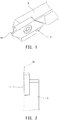
FIG. 1 ] Perspective view of an exemplary surface-coated cutting tool. - [
FIG. 2 ] Plan view of the surface-coated cutting tool. - [
FIG. 3 ] Explanatory view showing the results of analysis of a coating layer through X-ray diffractometry. - The surface-coated cutting tool includes a tool substrate, and a single-component coating layer composed of a composite nitride of Cr (chromium), Al (aluminum), and V (vanadium) and disposed on the surface of the tool substrate. The composite nitride is characterized by being represented by a compositional formula: CraAlbVcN satisfying the following relations:


- The term "single-component coating layer" refers to a coating layer substantially composed of a single material; i.e., a coating layer that has no interface between different components, as observed under an SEM (scanning electron microscope).
- No particular limitation is imposed on the tool substrate, and the tool substrate can be appropriately selected from those conventionally used widely in the field of cutting tools. Examples of preferred tool substrates include cemented carbide, cermet, sintered cubic boron nitride, ceramic materials (e.g., silicon carbide, silicon nitride, aluminum nitride, aluminum oxide, silicon carbide, titanium carbide, and composite materials thereof), and sintered diamond. Examples of the cemented carbide include WC-based cemented carbides, such as WC-Co alloys, WC-TiC-Co alloys, and WC-TiC-TaC-Co alloys.
- The surface-coated cutting tool can be applied to a variety of conventionally known cutting tools used for a cutting process. Examples of preferred surface-coated cutting tools include edge-exchangeable chips for turning or milling (e.g., cutting insert and throw-away chip), drills, end mills, metal saws, gear cutting tools, reamers, and taps.
- Now will be described an exemplary surface-coated cutting tool with reference to
FIGS. 1 and 2 . As shown in these figures, the surface-coated cutting tool is a grooving tool (cutting insert) 1. Thegrooving tool 1 has an approximately parallelogram shape in side view. Thegrooving tool 1 has a protrudingedge 1A. Thegrooving tool 1 is screwed into aholder 3 and is exchangeable. - In the surface-coated cutting tool, the coating layer is formed on the surface of the tool substrate. The coating layer has a single-layer structure and composed of a composite nitride of Cr, Al, and V. The composite nitride is represented by a compositional formula: CraAlbVcN satisfying the following relations:


- In the composition CraAlbVcN, a, b, and c preferably satisfy the following relations:


- When a, b, and c of CraAlbVcN satisfy the aforementioned relations, the surface-coated cutting tool exhibits improved adhesion resistance and wear resistance.
- When "b is less than 0.73," the coating layer has a single cubic phase, and the property of a hexagonal phase is difficult to achieve. When "b is more than 0.85," the coating layer is dominated by a hexagonal phase, and the property of a cubic phase is difficult to achieve. When b satisfies the relation "0.73 ≤ b ≤ 0.85," the single-component coating layer has both a cubic phase and a hexagonal phase and exhibits superior properties attributed to the cubic phase and the hexagonal phase.
- In the coating layer, "c is more than 0"; i.e., V is an essential component. Incorporation of V can improve the slidability between the coating layer and a work material. V has a low oxidation initiation temperature and preferentially adsorbs oxygen, to thereby form V2O5. V2O5 is expected to exhibit the effect of achieving a good slidability between the coating layer and a work material. However, when c is more than 0.04, the effect of V2O5 is dominant, resulting in a tendency of decreased hardness and thermal resistance of the coating layer. When c satisfies the relation "0 < c ≤ 0.04," a good slidability can be achieved between the coating layer and a work material while the hardness and thermal resistance of the coating layer are maintained.
- No particular limitation is imposed on the thickness of the single-component coating layer composed of a composite nitride of Cr, Al, and V. The thickness of the single-component coating layer is preferably 0.5 µm or more, more preferably 0.8 µm or more, particularly preferably 1.5 µm or more, in order to secure satisfactory adhesion resistance and wear resistance. The thickness of the coating layer is generally 10 µm or less.
- The thickness of the coating layer can be measured through observation of a cross section of the surface-coated cutting tool under an SEM.
- The single-component coating layer has both a hexagonal phase and a cubic phase. The presence of both the hexagonal phase and the cubic phase can be determined through X-ray diffractometry of the single-component coating layer.
FIG. 3 shows the results of X-ray diffraction analysis of a sample by means of an X-ray diffractometer using Cu-Kα rays. In -
FIG. 3 , the horizontal axis corresponds to the diffraction angle 2θ of a peak, and the vertical axis corresponds to diffraction intensity. The peaks of (111) plane of the cubic phase, (200) plane of the cubic phase, and (100) plane of the hexagonal phase are observed at positions described below. The presence of the hexagonal phase and the cubic phase can be determined on the basis of the presence or absence of the peaks at these positions. In the present embodiment, the peaks attributed to the hexagonal phase and the cubic phase are observed, since the coating layer has both the hexagonal phase and the cubic phase. - Peak of (111) plane of the cubic phase: 37.7°
- Peak of (200) plane of the cubic phase: 43.8°
- Peak of (100) plane of the hexagonal phase: 32.6°
- In the present embodiment, the single-component coating layer preferably exhibits a specific peak intensity ratio (IA/IB) as determined through X-ray diffractometry, wherein IA represents the peak intensity of (111) plane of the cubic phase, and IB represents the peak intensity of (100) plane of the hexagonal phase. Specifically, the peak intensity ratio (IA/IB) is preferably 1.5 or more and 5.8 or less, more preferably 5.5 or more and 5.8 or less.
- The peak intensity ratio (IA/IB) corresponds to the ratio of the amount of the cubic phase to that of the hexagonal phase. A peak intensity ratio (IA/IB) of less than 1.5 causes the hexagonal phase to have a dominant influence. This may lead to a tendency of decreased hardness of the coating layer, resulting in improved adhesion resistance, but impaired wear resistance.
- Meanwhile, a peak intensity ratio (IA/IB) of more than 5.8 causes the cubic phase to have a dominant influence. This may lead to an increase in the hardness of the coating layer, resulting in improved wear resistance, but impaired adhesion resistance.
- When the peak intensity ratio (IA/IB) falls within a range of 1.5 or more and 5.8 or less, the coating layer exhibits both adhesion resistance and wear resistance; i.e., the superior properties attributed to the hexagonal phase and the cubic phase, respectively.
- In the present embodiment, the single-component coating layer exhibits a specific peak intensity ratio (IA/IC) as determined through X-ray diffractometry, wherein IC represents the peak intensity of (200) plane of the cubic phase. The peak intensity ratio (IA/IC) is preferably 0.9 or more, more preferably 1.6 or more. The upper limit of the peak intensity ratio (IA/IC) is generally 5.0.
- The peak intensity ratio (IA/IC) corresponds to the ratio of the peak intensity of (111) plane of the cubic phase to that of the (200) plane of the cubic phase. A non-oriented coating layer has a peak intensity ratio (IA/IC) of about 0.9. A peak intensity ratio (IA/IC) of 0.9 or more can lead to an improvement in breakage resistance.
- The surface-coated cutting tool of the present embodiment may include a coating layer (hereinafter may be referred to as "additional coating layer") other than the single-component coating layer composed of a composite nitride of Cr, Al, and V.
- No particular limitation is imposed on the additional coating layer, and the additional coating layer is preferably, for example, a layer composed of TiN, TiCN, TiAlN, or CrAlN. No particular limitation is imposed on the thickness of the additional coating layer. The additional coating layer may be located inside (tool substrate side) or outside of the single-component coating layer composed of a composite nitride of Cr, Al, and V. No particular limitation is imposed on the number of layers forming the additional coating layer, and the additional coating layer may have a single-layer or multi-layer structure. When the additional coating layer has a multi-layer structure, the additional coating layer may be formed of layers having the same composition or different compositions.
- In the surface-coated cutting tool of the present embodiment, the single-component coating layer composed of a composite nitride of Cr, Al, and V has both a hexagonal phase and a cubic phase. The single-component coating layer is harder than a layered film according to the aforementioned conventional technique (Patent Document 1). Conceivably, the performance of the coating layer is less likely to be impaired, and thus the coating layer contributes to an improvement in cutting ability.
- The surface-coated cutting tool of the present invention exhibits adhesion resistance higher than that of a conventional product by reducing the affinity of the tool surface to a work material; i.e., by reducing the amount of an iron group element contained in the coating layer. The control of the amount of Al, Cr, or V enables the coating layer to have both a cubic phase and a hexagonal phase and to improve its properties.
- Incorporation of V into the coating layer can improve the slidability between the coating layer and a work material. V has a low oxidation initiation temperature and preferentially adsorbs oxygen, to thereby form V2O5. V2O5 is expected to exhibit the effect of achieving a good slidability between the coating layer and a work material.
- The breakage resistance or chipping resistance of the cutting tool is improved, and the service life of the tool is prolonged through achievement of the (111) orientation; i.e., a peak intensity ratio (IA/IC) of 0.9 or more. As used herein, the term "chipping resistance" refers to the case where a tool is less likely to be chipped.
- No particular limitation is imposed on the method for producing the surface-coated cutting tool. For example, the single-component coating layer composed of a composite nitride of Cr, Al, and V can be formed on the surface of the tool substrate through arc ion plating. In this production method, a desired surface-coated cutting tool can be produced by controlling the conditions for forming the surface coating layer. In the present embodiment, the coating layer formed on the surface of the tool substrate is composed of a composite nitride of Cr, Al, and V and has a single-layer structure. Thus, the coating layer is formed by use of one type of target (evaporation source); specifically an alloy target containing Al, Cr, and V. This formation involves the use of nitrogen gas as a reaction gas.
- The present invention will next be described in more detail by way of examples.
- The tool substrate used was cemented carbide (grade: JIS K type) having a chip shape for grooving. The tool substrate was placed in a cathode arc ion plating apparatus.
- While the chamber of the apparatus was evacuated by means of a vacuum pump until a pressure of 4.0 × 10⁻³ Pa was achieved in the chamber, the tool substrate placed in the apparatus was heated to a temperature of 500°C by means of a heater. Subsequently, argon gas was introduced into the apparatus so as to maintain a pressure of 1.0 Pa in the chamber, and the substrate bias voltage was gradually increased to -350 V, to thereby clean the surface of the tool substrate for 20 minutes. Thereafter, the argon gas was discharged.
- Subsequently, an alloy target containing Al, Cr, and V was placed in the apparatus. While nitrogen gas serving as a reaction was introduced and the following conditions were maintained (substrate temperature: 500°C, reaction gas pressure: 1.0 Pa, and substrate bias voltage: -30 V), an arc current of 100 A was supplied to a cathode, and metal ions were generated from an arc evaporation source, to thereby form a coating layer (thickness: 1.5 µm) at a cutting edge. The evaporation source used in the present invention is characterized in that magnetic field lines extend to a work material, and the plasma density of a film formation gas in the vicinity of the work material is considerably high as compared with the case of a conventional evaporation source. Surface-coated cutting tools of Comparative Examples 1 to 4 were produced by appropriately regulating the aforementioned conditions for formation of a coating layer.
- Thus, surface-coated cutting tools of Examples 1 to 4 and Comparative Examples 1 to 4 were produced as shown in Table 1. The coating layer of each of the surface-coated cutting tools was analyzed by means of an X-ray diffractometer (RINT-TTR3, manufactured by Rigaku Corporation) using Cu-Kα rays.
- In Examples 1 to 4 and Comparative Examples 1 to 4, the composition and crystal phases of the surface coating layer were varied as shown in Table 1 through regulation of the proportions of Al, Cr, and V contained in the alloy target.
- Each of the surface-coated cutting tools was used for cutting off under the conditions described below, and the flank wear width of the cutting edge was measured after 300 passes. The cutting conditions were as follows: work material: SUS304 (Φ20), cutting rate: 60 m/min, and feed rate: 0.05 mm/rev.
- Test results are shown in Table 1.
[Table 1] Coating layer thickness (µm) Composition of coating layer Crystalline phase IA/IB IA/IC Wear width (µm) Ex. 1 1.5 Cr0.26Al0.73V0.01N Hexagonal + cubic 5.8 0.9 29 Ex. 2 1.5 Cr0.17Al0.82V0.01N Hexagonal + cubic 2.6 2.1 30 Ex. 3 1. 5 Cr0.23Al0.75V0.02N Hexagonal + cubic 5.5 1.6 27 Ex. 4 1.5 Cr0.21Al0.75V0.04N Hexagonal + cubic 4.0 1.7 31 Ex. 5 1.5 Cr0.11Al0.85V0.04N Hexagonal + cubic 1.5 2.7 34 Comp. Ex. 1 1.5 Cr0.34Al0.65 V0.01N Cubic - 0.7 57 Comp. Ex. 2 1.5 Cr0.09Al0.90V0.01N Hexagonal + cubic 0. 3 1.5 51 Comp. Ex. 3 1.5 Cr0.3Al0.7N Cubic - 0.7 40 Comp. Ex. 4 1.5 Cr0.15Al0.75V0.1N Hexagonal + cubic 0.7 1. 9 53 - The surface-coated cutting tools of Examples 1 to 5, in which the composition CraAlbVcN of the coating layer satisfied the following relations: 0.11 ≤ a ≤ 0.26, 0.73 ≤ b ≤ 0.85, and 0 < c ≤ 0.04, were found to have small wear width; i.e., improved wear resistance, as compared with the surface-coated cutting tools of Comparative Examples 1 to 4.
- The surface-coated cutting tools of Examples 1 to 4 were found to generate almost no chipping, which would otherwise be caused by adhesion/peeling.
- In Comparative Example 1, the coating layer had a single cubic phase because of low Al content. Thus, the property of a hexagonal phase failed to be achieved, and adhesion resistance was impaired. This led to adhesion/peeling, resulting in chipping and thus wear.
- In Comparative Example 2, high Al content caused the hexagonal phase to have a dominant influence, resulting in wear.
- Comparative Example 3 corresponds to the case where a conventional CrAlN coating layer was used. In Comparative Example 3, the coating layer had a single cubic phase because of the absence of V and a relatively low Al content. Thus, the property of a hexagonal phase failed to be achieved, and adhesion resistance was impaired. This led to adhesion/peeling, resulting in chipping and thus wear.
- In Comparative Example 4, high V content caused the hexagonal phase to have a dominant influence, resulting in wear. In Comparative Example 4, thermal resistance was impaired.
- Now will be described the effect of peak intensity ratio (IA/IB) on wear. Each of the surface-coated cutting tools of Examples 1 to 5, in which the coating layer exhibited a peak intensity ratio (IA/IB) of 1.5 or more and 5.8 or less, was found to have a small wear width.
- In Comparative Examples 1 and 3, the coating layer had only a cubic phase, and thus the peak intensity ratio (IA/IB) was not calculated. Each of the surface-coated cutting tools of Comparative Examples 2 and 4, in which the coating layer exhibited a peak intensity ratio (IA/IB) of less than 1.5, was found to have a large wear width.
- These results indicated that the coating layer exhibiting a peak intensity ratio (IA/IB) of 1.5 or more and 5.8 or less has both adhesion resistance and wear resistance.
- Now will be described the effect of peak intensity ratio (IA/IC) on wear. Each of the surface-coated cutting tools of Examples 1 to 5, in which the coating layer exhibited a peak intensity ratio (IA/IC) of 0.9 or more, was found to have a small wear width.
- Each of the surface-coated cutting tools of Comparative Examples 1 and 3, in which the coating layer exhibited a peak intensity ratio (IA/IC) of less than 0.9, was found to have a large wear width. In Comparative Examples 2 and 4, the peak intensity ratio (IA/IC) is 0.9 or more, but the composition of the coating layer falls outside the scope of the present invention.
- These results indicated that the coating layer exhibiting a peak intensity ratio (IA/IC) of 0.9 or more has both adhesion resistance and wear resistance.
- Now will be described the detailed comparison between Examples 1 and 3. In Examples 1 and 3, the peak intensity ratios (IA/IB) are approximate with each other. However, the peak intensity ratio (IA/IC) in Example 1 is 0.9, which is smaller than that in Example 3; i.e., 1.6. The wear width in Example 3 is smaller than that in Example 1. These results indicate that a peak intensity ratio (IA/IC) of 1.6 or more achieves very good wear resistance.
- According to the present examples, the surface-coated cutting tool exhibits improved adhesion resistance and wear resistance upon cutting of a work material that is likely to cause adhesion on a cutting edge, such as low-carbon steel, stainless steel material, or ductile cast iron. Thus, the surface-coated cutting tool exhibits long service life.
- In the present examples, the single-component coating layer composed of a composite nitride of Cr, Al, and V has both a hexagonal phase and a cubic phase. The single-component coating layer has adhesion resistance superior to that of the layered product according to the aforementioned conventional technique (Patent Document 1) or a cubic-phase single layer. Thus, the single-component coating layer can contribute to reduction in tool damage, which would otherwise be caused by adhesion.
- The coating layer exhibiting a peak intensity ratio (IA/IC) of 0.9 or more has excellent breakage resistance and enables the tool to have prolonged service life.
- The present invention is not limited to the examples and embodiments described above, but may be implemented in various other forms without departing from the scope of the invention.
- (1) The present invention has been described by taking a grooving tool as an example in the aforementioned embodiment. However, the present invention can be applied to various cutting tools used for a cutting process.
-
- 1:
- grooving tool
- 11A:
- edge
- 3:
- holder
Claims (4)
- A surface-coated cutting tool comprising a tool substrate, and a single-component coating layer composed of a composite nitride of Cr, Al, and V and disposed on the surface of the tool substrate, wherein
the composite nitride being represented by a compositional formula: CraAlbVcN satisfying the following relations:


- A surface-coated cutting tool according to claim 1, wherein the single-component coating layer has both a hexagonal phase and a cubic phase.
- A surface-coated cutting tool according to claim 2, wherein the single-component coating layer exhibits a peak intensity ratio (IA/IB) of 1.5 or more and 5.8 or less as determined by X-ray diffractometry, whereinIA represents the peak intensity of (111) plane of the cubic phase, andIB represents the peak intensity of (100) plane of the hexagonal phase.
- A surface-coated cutting tool according to claim 2 or 3, wherein the single-component coating layer exhibits a peak intensity ratio (IA/IC) of 0.9 or more as determined through X-ray diffractometry, wherein
IC represents the peak intensity of (200) plane of the cubic phase.
Applications Claiming Priority (2)
| Application Number | Priority Date | Filing Date | Title |
|---|---|---|---|
| JP2017115123A JP6830410B2 (en) | 2017-06-12 | 2017-06-12 | Surface coating cutting tool |
| PCT/JP2018/018255 WO2018230212A1 (en) | 2017-06-12 | 2018-05-11 | Cutting tool for surface coating |
Publications (3)
| Publication Number | Publication Date |
|---|---|
| EP3653323A1 true EP3653323A1 (en) | 2020-05-20 |
| EP3653323A4 EP3653323A4 (en) | 2021-03-24 |
| EP3653323B1 EP3653323B1 (en) | 2022-11-30 |
Family
ID=64660456
Family Applications (1)
| Application Number | Title | Priority Date | Filing Date |
|---|---|---|---|
| EP18818446.9A Active EP3653323B1 (en) | 2017-06-12 | 2018-05-11 | Cutting tool for surface coating |
Country Status (7)
| Country | Link |
|---|---|
| US (1) | US11173555B2 (en) |
| EP (1) | EP3653323B1 (en) |
| JP (1) | JP6830410B2 (en) |
| KR (1) | KR102211259B1 (en) |
| CN (1) | CN110730698B (en) |
| ES (1) | ES2933813T3 (en) |
| WO (1) | WO2018230212A1 (en) |
Families Citing this family (3)
| Publication number | Priority date | Publication date | Assignee | Title |
|---|---|---|---|---|
| JP7247452B2 (en) * | 2019-03-25 | 2023-03-29 | 株式会社Moldino | coated tool |
| US11103944B2 (en) * | 2019-08-12 | 2021-08-31 | Deere & Company | Self-sharpening cutting tooth for a felling apparatus |
| CN112708859A (en) * | 2020-12-21 | 2021-04-27 | 华南理工大学 | Tool with anti-friction and anti-wear CrAlVN coating and preparation method thereof |
Family Cites Families (10)
| Publication number | Priority date | Publication date | Assignee | Title |
|---|---|---|---|---|
| DE10233222B4 (en) * | 2001-07-23 | 2007-03-01 | Kabushiki Kaisha Kobe Seiko Sho (Kobe Steel, Ltd.), Kobe | Hard wear-resistant layer, method of forming same and use |
| JP2005271190A (en) | 2003-12-05 | 2005-10-06 | Sumitomo Electric Hardmetal Corp | Surface coated cutting tool |
| JP4575009B2 (en) * | 2004-03-25 | 2010-11-04 | 住友電工ハードメタル株式会社 | Coated cutting tool |
| JP4445815B2 (en) | 2004-07-14 | 2010-04-07 | 住友電工ハードメタル株式会社 | Surface coated cutting tool |
| KR101200785B1 (en) * | 2007-10-12 | 2012-11-13 | 히타치 쓰루 가부시키가이샤 | Member covered with hard coating film and process for the production of the member |
| JP2009101491A (en) * | 2007-10-25 | 2009-05-14 | Mitsubishi Materials Corp | Surface coated cutting tool with excellent lubricity and wear resistance with high hard coating layer in high speed cutting |
| JP2011127205A (en) * | 2009-12-21 | 2011-06-30 | Hitachi Tool Engineering Ltd | Coated die having excellent lubricant adhesiveness and durability, and method for producing the same |
| JP5440351B2 (en) * | 2010-04-16 | 2014-03-12 | 三菱マテリアル株式会社 | Surface coated cutting tool |
| CN104385751B (en) * | 2014-08-29 | 2016-07-06 | 株洲钻石切削刀具股份有限公司 | Composite coating layer cutter containing CrAlVN layer and CrAlSiN layer and preparation method thereof |
| JP6789503B2 (en) * | 2016-06-28 | 2020-11-25 | 株式会社不二越 | Hard film film formation method |
-
2017
- 2017-06-12 JP JP2017115123A patent/JP6830410B2/en active Active
-
2018
- 2018-05-11 WO PCT/JP2018/018255 patent/WO2018230212A1/en not_active Ceased
- 2018-05-11 US US16/620,716 patent/US11173555B2/en active Active
- 2018-05-11 ES ES18818446T patent/ES2933813T3/en active Active
- 2018-05-11 CN CN201880037915.6A patent/CN110730698B/en active Active
- 2018-05-11 KR KR1020197036332A patent/KR102211259B1/en active Active
- 2018-05-11 EP EP18818446.9A patent/EP3653323B1/en active Active
Also Published As
| Publication number | Publication date |
|---|---|
| JP2019000919A (en) | 2019-01-10 |
| JP6830410B2 (en) | 2021-02-17 |
| US20200122248A1 (en) | 2020-04-23 |
| KR102211259B1 (en) | 2021-02-02 |
| CN110730698A (en) | 2020-01-24 |
| ES2933813T3 (en) | 2023-02-14 |
| KR20200004398A (en) | 2020-01-13 |
| EP3653323B1 (en) | 2022-11-30 |
| WO2018230212A1 (en) | 2018-12-20 |
| EP3653323A4 (en) | 2021-03-24 |
| US11173555B2 (en) | 2021-11-16 |
| CN110730698B (en) | 2021-08-24 |
Similar Documents
| Publication | Publication Date | Title |
|---|---|---|
| KR100653001B1 (en) | Hard film for cutting tools, cutting tool coated with hard film, process for forming hard film, and target used to form hard film | |
| EP3170919B1 (en) | Coated cutting tool | |
| EP2623241B1 (en) | Cutting tool | |
| EP1710326A1 (en) | Surface-coated cutting tool | |
| EP3228726A1 (en) | Coated cutting tool | |
| EP2636764A1 (en) | Nanolaminated coated cutting tool | |
| EP3360632B1 (en) | Coated cutting tool | |
| JP7649468B2 (en) | Surface-coated cutting tools | |
| EP4570945A1 (en) | Coating cutting tool | |
| JP2021126738A (en) | Surface coating cutting tool that demonstrates excellent chipping resistance and wear resistance in strong intermittent cutting | |
| EP3653323B1 (en) | Cutting tool for surface coating | |
| EP3456867A1 (en) | Coated drill | |
| JP2023118793A (en) | Cutting tools | |
| EP4147808B1 (en) | Cutting tool | |
| EP1440754A1 (en) | Surface coated cemented carbide cutting tool having hard coating layer exhibiting excellent wear resistance in high speed machining | |
| EP1710032A1 (en) | Cutting tool made of surface-coated super hard alloy, and method for manufacture thereof | |
| JP2018164961A (en) | Surface-coated cutting tool in which hard coating layer exhibits excellent wear resistance and chipping resistance, and method for producing the same | |
| KR102353655B1 (en) | clad cutting tool | |
| JP7520286B2 (en) | Surface-coated cutting tools | |
| WO2022176058A1 (en) | Cutting tool | |
| US11623284B2 (en) | Surface-coated cutting tool | |
| JP5035979B2 (en) | Surface-coated cutting tool that exhibits high wear resistance with a hard coating layer in high-speed milling and a method for producing the same | |
| JP4210930B2 (en) | Surface-coated throw-away tip that exhibits excellent chipping resistance with a hard coating layer in high-speed intermittent cutting | |
| JP3371823B2 (en) | Surface coated cemented carbide cutting tool with excellent interlayer adhesion with hard coating layer | |
| JP4748444B2 (en) | Surface-coated cermet cutting tool that exhibits excellent chipping resistance with a hard coating layer in high-speed cutting of difficult-to-cut materials |
Legal Events
| Date | Code | Title | Description |
|---|---|---|---|
| STAA | Information on the status of an ep patent application or granted ep patent |
Free format text: STATUS: THE INTERNATIONAL PUBLICATION HAS BEEN MADE |
|
| PUAI | Public reference made under article 153(3) epc to a published international application that has entered the european phase |
Free format text: ORIGINAL CODE: 0009012 |
|
| STAA | Information on the status of an ep patent application or granted ep patent |
Free format text: STATUS: REQUEST FOR EXAMINATION WAS MADE |
|
| 17P | Request for examination filed |
Effective date: 20191211 |
|
| AK | Designated contracting states |
Kind code of ref document: A1 Designated state(s): AL AT BE BG CH CY CZ DE DK EE ES FI FR GB GR HR HU IE IS IT LI LT LU LV MC MK MT NL NO PL PT RO RS SE SI SK SM TR |
|
| AX | Request for extension of the european patent |
Extension state: BA ME |
|
| DAV | Request for validation of the european patent (deleted) | ||
| DAX | Request for extension of the european patent (deleted) | ||
| A4 | Supplementary search report drawn up and despatched |
Effective date: 20210223 |
|
| RIC1 | Information provided on ipc code assigned before grant |
Ipc: C23C 14/06 20060101ALI20210217BHEP Ipc: B23B 27/14 20060101AFI20210217BHEP |
|
| REG | Reference to a national code |
Ref country code: DE Ref legal event code: R079 Ref document number: 602018043752 Country of ref document: DE Free format text: PREVIOUS MAIN CLASS: B23B0027140000 Ipc: C23C0014000000 |
|
| RIC1 | Information provided on ipc code assigned before grant |
Ipc: C23C 14/06 20060101ALI20220607BHEP Ipc: C23C 14/32 20060101ALI20220607BHEP Ipc: C23C 14/00 20060101AFI20220607BHEP |
|
| GRAP | Despatch of communication of intention to grant a patent |
Free format text: ORIGINAL CODE: EPIDOSNIGR1 |
|
| STAA | Information on the status of an ep patent application or granted ep patent |
Free format text: STATUS: GRANT OF PATENT IS INTENDED |
|
| INTG | Intention to grant announced |
Effective date: 20220801 |
|
| RIN1 | Information on inventor provided before grant (corrected) |
Inventor name: KOMURA, ATSUSHI Inventor name: KIKKAWA, FUMIHIRO Inventor name: NOZAKI, SHOTA |
|
| RAP3 | Party data changed (applicant data changed or rights of an application transferred) |
Owner name: NGK SPARK PLUG CO., LTD. |
|
| GRAS | Grant fee paid |
Free format text: ORIGINAL CODE: EPIDOSNIGR3 |
|
| GRAA | (expected) grant |
Free format text: ORIGINAL CODE: 0009210 |
|
| STAA | Information on the status of an ep patent application or granted ep patent |
Free format text: STATUS: THE PATENT HAS BEEN GRANTED |
|
| AK | Designated contracting states |
Kind code of ref document: B1 Designated state(s): AL AT BE BG CH CY CZ DE DK EE ES FI FR GB GR HR HU IE IS IT LI LT LU LV MC MK MT NL NO PL PT RO RS SE SI SK SM TR |
|
| REG | Reference to a national code |
Ref country code: CH Ref legal event code: EP Ref country code: GB Ref legal event code: FG4D |
|
| REG | Reference to a national code |
Ref country code: AT Ref legal event code: REF Ref document number: 1534727 Country of ref document: AT Kind code of ref document: T Effective date: 20221215 Ref country code: DE Ref legal event code: R096 Ref document number: 602018043752 Country of ref document: DE |
|
| REG | Reference to a national code |
Ref country code: IE Ref legal event code: FG4D |
|
| REG | Reference to a national code |
Ref country code: ES Ref legal event code: FG2A Ref document number: 2933813 Country of ref document: ES Kind code of ref document: T3 Effective date: 20230214 |
|
| REG | Reference to a national code |
Ref country code: LT Ref legal event code: MG9D |
|
| REG | Reference to a national code |
Ref country code: NL Ref legal event code: MP Effective date: 20221130 |
|
| PG25 | Lapsed in a contracting state [announced via postgrant information from national office to epo] |
Ref country code: SE Free format text: LAPSE BECAUSE OF FAILURE TO SUBMIT A TRANSLATION OF THE DESCRIPTION OR TO PAY THE FEE WITHIN THE PRESCRIBED TIME-LIMIT Effective date: 20221130 Ref country code: PT Free format text: LAPSE BECAUSE OF FAILURE TO SUBMIT A TRANSLATION OF THE DESCRIPTION OR TO PAY THE FEE WITHIN THE PRESCRIBED TIME-LIMIT Effective date: 20230331 Ref country code: NO Free format text: LAPSE BECAUSE OF FAILURE TO SUBMIT A TRANSLATION OF THE DESCRIPTION OR TO PAY THE FEE WITHIN THE PRESCRIBED TIME-LIMIT Effective date: 20230228 Ref country code: LT Free format text: LAPSE BECAUSE OF FAILURE TO SUBMIT A TRANSLATION OF THE DESCRIPTION OR TO PAY THE FEE WITHIN THE PRESCRIBED TIME-LIMIT Effective date: 20221130 Ref country code: FI Free format text: LAPSE BECAUSE OF FAILURE TO SUBMIT A TRANSLATION OF THE DESCRIPTION OR TO PAY THE FEE WITHIN THE PRESCRIBED TIME-LIMIT Effective date: 20221130 |
|
| REG | Reference to a national code |
Ref country code: AT Ref legal event code: MK05 Ref document number: 1534727 Country of ref document: AT Kind code of ref document: T Effective date: 20221130 |
|
| PG25 | Lapsed in a contracting state [announced via postgrant information from national office to epo] |
Ref country code: RS Free format text: LAPSE BECAUSE OF FAILURE TO SUBMIT A TRANSLATION OF THE DESCRIPTION OR TO PAY THE FEE WITHIN THE PRESCRIBED TIME-LIMIT Effective date: 20221130 Ref country code: PL Free format text: LAPSE BECAUSE OF FAILURE TO SUBMIT A TRANSLATION OF THE DESCRIPTION OR TO PAY THE FEE WITHIN THE PRESCRIBED TIME-LIMIT Effective date: 20221130 Ref country code: LV Free format text: LAPSE BECAUSE OF FAILURE TO SUBMIT A TRANSLATION OF THE DESCRIPTION OR TO PAY THE FEE WITHIN THE PRESCRIBED TIME-LIMIT Effective date: 20221130 Ref country code: IS Free format text: LAPSE BECAUSE OF FAILURE TO SUBMIT A TRANSLATION OF THE DESCRIPTION OR TO PAY THE FEE WITHIN THE PRESCRIBED TIME-LIMIT Effective date: 20230330 Ref country code: HR Free format text: LAPSE BECAUSE OF FAILURE TO SUBMIT A TRANSLATION OF THE DESCRIPTION OR TO PAY THE FEE WITHIN THE PRESCRIBED TIME-LIMIT Effective date: 20221130 Ref country code: GR Free format text: LAPSE BECAUSE OF FAILURE TO SUBMIT A TRANSLATION OF THE DESCRIPTION OR TO PAY THE FEE WITHIN THE PRESCRIBED TIME-LIMIT Effective date: 20230301 |
|
| PG25 | Lapsed in a contracting state [announced via postgrant information from national office to epo] |
Ref country code: NL Free format text: LAPSE BECAUSE OF FAILURE TO SUBMIT A TRANSLATION OF THE DESCRIPTION OR TO PAY THE FEE WITHIN THE PRESCRIBED TIME-LIMIT Effective date: 20221130 |
|
| PG25 | Lapsed in a contracting state [announced via postgrant information from national office to epo] |
Ref country code: SM Free format text: LAPSE BECAUSE OF FAILURE TO SUBMIT A TRANSLATION OF THE DESCRIPTION OR TO PAY THE FEE WITHIN THE PRESCRIBED TIME-LIMIT Effective date: 20221130 Ref country code: RO Free format text: LAPSE BECAUSE OF FAILURE TO SUBMIT A TRANSLATION OF THE DESCRIPTION OR TO PAY THE FEE WITHIN THE PRESCRIBED TIME-LIMIT Effective date: 20221130 Ref country code: EE Free format text: LAPSE BECAUSE OF FAILURE TO SUBMIT A TRANSLATION OF THE DESCRIPTION OR TO PAY THE FEE WITHIN THE PRESCRIBED TIME-LIMIT Effective date: 20221130 Ref country code: DK Free format text: LAPSE BECAUSE OF FAILURE TO SUBMIT A TRANSLATION OF THE DESCRIPTION OR TO PAY THE FEE WITHIN THE PRESCRIBED TIME-LIMIT Effective date: 20221130 Ref country code: CZ Free format text: LAPSE BECAUSE OF FAILURE TO SUBMIT A TRANSLATION OF THE DESCRIPTION OR TO PAY THE FEE WITHIN THE PRESCRIBED TIME-LIMIT Effective date: 20221130 Ref country code: AT Free format text: LAPSE BECAUSE OF FAILURE TO SUBMIT A TRANSLATION OF THE DESCRIPTION OR TO PAY THE FEE WITHIN THE PRESCRIBED TIME-LIMIT Effective date: 20221130 |
|
| PG25 | Lapsed in a contracting state [announced via postgrant information from national office to epo] |
Ref country code: SK Free format text: LAPSE BECAUSE OF FAILURE TO SUBMIT A TRANSLATION OF THE DESCRIPTION OR TO PAY THE FEE WITHIN THE PRESCRIBED TIME-LIMIT Effective date: 20221130 Ref country code: AL Free format text: LAPSE BECAUSE OF FAILURE TO SUBMIT A TRANSLATION OF THE DESCRIPTION OR TO PAY THE FEE WITHIN THE PRESCRIBED TIME-LIMIT Effective date: 20221130 |
|
| REG | Reference to a national code |
Ref country code: DE Ref legal event code: R097 Ref document number: 602018043752 Country of ref document: DE |
|
| PLBE | No opposition filed within time limit |
Free format text: ORIGINAL CODE: 0009261 |
|
| STAA | Information on the status of an ep patent application or granted ep patent |
Free format text: STATUS: NO OPPOSITION FILED WITHIN TIME LIMIT |
|
| REG | Reference to a national code |
Ref country code: DE Ref legal event code: R081 Ref document number: 602018043752 Country of ref document: DE Owner name: NTK CUTTING TOOLS CO., LTD., KOMAKI-SHI, JP Free format text: FORMER OWNER: NGK SPARK PLUG CO., LTD., NAGOYA-SHI, AICHI, JP |
|
| 26N | No opposition filed |
Effective date: 20230831 |
|
| PG25 | Lapsed in a contracting state [announced via postgrant information from national office to epo] |
Ref country code: SI Free format text: LAPSE BECAUSE OF FAILURE TO SUBMIT A TRANSLATION OF THE DESCRIPTION OR TO PAY THE FEE WITHIN THE PRESCRIBED TIME-LIMIT Effective date: 20221130 |
|
| REG | Reference to a national code |
Ref country code: CH Ref legal event code: PL |
|
| PG25 | Lapsed in a contracting state [announced via postgrant information from national office to epo] |
Ref country code: MC Free format text: LAPSE BECAUSE OF FAILURE TO SUBMIT A TRANSLATION OF THE DESCRIPTION OR TO PAY THE FEE WITHIN THE PRESCRIBED TIME-LIMIT Effective date: 20221130 |
|
| GBPC | Gb: european patent ceased through non-payment of renewal fee |
Effective date: 20230511 |
|
| REG | Reference to a national code |
Ref country code: BE Ref legal event code: MM Effective date: 20230531 |
|
| PG25 | Lapsed in a contracting state [announced via postgrant information from national office to epo] |
Ref country code: MC Free format text: LAPSE BECAUSE OF FAILURE TO SUBMIT A TRANSLATION OF THE DESCRIPTION OR TO PAY THE FEE WITHIN THE PRESCRIBED TIME-LIMIT Effective date: 20221130 Ref country code: LU Free format text: LAPSE BECAUSE OF NON-PAYMENT OF DUE FEES Effective date: 20230511 Ref country code: LI Free format text: LAPSE BECAUSE OF NON-PAYMENT OF DUE FEES Effective date: 20230531 Ref country code: CH Free format text: LAPSE BECAUSE OF NON-PAYMENT OF DUE FEES Effective date: 20230531 |
|
| REG | Reference to a national code |
Ref country code: IE Ref legal event code: MM4A |
|
| PG25 | Lapsed in a contracting state [announced via postgrant information from national office to epo] |
Ref country code: IE Free format text: LAPSE BECAUSE OF NON-PAYMENT OF DUE FEES Effective date: 20230511 |
|
| PG25 | Lapsed in a contracting state [announced via postgrant information from national office to epo] |
Ref country code: IE Free format text: LAPSE BECAUSE OF NON-PAYMENT OF DUE FEES Effective date: 20230511 Ref country code: GB Free format text: LAPSE BECAUSE OF NON-PAYMENT OF DUE FEES Effective date: 20230511 |
|
| PG25 | Lapsed in a contracting state [announced via postgrant information from national office to epo] |
Ref country code: FR Free format text: LAPSE BECAUSE OF NON-PAYMENT OF DUE FEES Effective date: 20230531 Ref country code: BE Free format text: LAPSE BECAUSE OF NON-PAYMENT OF DUE FEES Effective date: 20230531 |
|
| REG | Reference to a national code |
Ref country code: ES Ref legal event code: PC2A Owner name: NTK CUTTING TOOLS CO., LTD. Effective date: 20240612 |
|
| PG25 | Lapsed in a contracting state [announced via postgrant information from national office to epo] |
Ref country code: BG Free format text: LAPSE BECAUSE OF FAILURE TO SUBMIT A TRANSLATION OF THE DESCRIPTION OR TO PAY THE FEE WITHIN THE PRESCRIBED TIME-LIMIT Effective date: 20221130 |
|
| PG25 | Lapsed in a contracting state [announced via postgrant information from national office to epo] |
Ref country code: BG Free format text: LAPSE BECAUSE OF FAILURE TO SUBMIT A TRANSLATION OF THE DESCRIPTION OR TO PAY THE FEE WITHIN THE PRESCRIBED TIME-LIMIT Effective date: 20221130 |
|
| PG25 | Lapsed in a contracting state [announced via postgrant information from national office to epo] |
Ref country code: CY Free format text: LAPSE BECAUSE OF FAILURE TO SUBMIT A TRANSLATION OF THE DESCRIPTION OR TO PAY THE FEE WITHIN THE PRESCRIBED TIME-LIMIT; INVALID AB INITIO Effective date: 20180511 |
|
| PG25 | Lapsed in a contracting state [announced via postgrant information from national office to epo] |
Ref country code: HU Free format text: LAPSE BECAUSE OF FAILURE TO SUBMIT A TRANSLATION OF THE DESCRIPTION OR TO PAY THE FEE WITHIN THE PRESCRIBED TIME-LIMIT; INVALID AB INITIO Effective date: 20180511 |
|
| PGFP | Annual fee paid to national office [announced via postgrant information from national office to epo] |
Ref country code: ES Payment date: 20250708 Year of fee payment: 8 |
|
| PG25 | Lapsed in a contracting state [announced via postgrant information from national office to epo] |
Ref country code: TR Free format text: LAPSE BECAUSE OF FAILURE TO SUBMIT A TRANSLATION OF THE DESCRIPTION OR TO PAY THE FEE WITHIN THE PRESCRIBED TIME-LIMIT Effective date: 20221130 |
|
| PGFP | Annual fee paid to national office [announced via postgrant information from national office to epo] |
Ref country code: IT Payment date: 20260414 Year of fee payment: 9 |
|
| PGFP | Annual fee paid to national office [announced via postgrant information from national office to epo] |
Ref country code: DE Payment date: 20260410 Year of fee payment: 9 |