EP3653273B1 - Modular crossbar - Google Patents
Modular crossbar Download PDFInfo
- Publication number
- EP3653273B1 EP3653273B1 EP19205929.3A EP19205929A EP3653273B1 EP 3653273 B1 EP3653273 B1 EP 3653273B1 EP 19205929 A EP19205929 A EP 19205929A EP 3653273 B1 EP3653273 B1 EP 3653273B1
- Authority
- EP
- European Patent Office
- Prior art keywords
- frame
- members
- apertures
- insert
- plate
- Prior art date
- Legal status (The legal status is an assumption and is not a legal conclusion. Google has not performed a legal analysis and makes no representation as to the accuracy of the status listed.)
- Revoked
Links
Images


Classifications
-
- A—HUMAN NECESSITIES
- A63—SPORTS; GAMES; AMUSEMENTS
- A63B—APPARATUS FOR PHYSICAL TRAINING, GYMNASTICS, SWIMMING, CLIMBING, OR FENCING; BALL GAMES; TRAINING EQUIPMENT
- A63B63/00—Targets or goals for ball games
-
- A—HUMAN NECESSITIES
- A63—SPORTS; GAMES; AMUSEMENTS
- A63B—APPARATUS FOR PHYSICAL TRAINING, GYMNASTICS, SWIMMING, CLIMBING, OR FENCING; BALL GAMES; TRAINING EQUIPMENT
- A63B63/00—Targets or goals for ball games
- A63B63/004—Goals of the type used for football, handball, hockey or the like
-
- A—HUMAN NECESSITIES
- A63—SPORTS; GAMES; AMUSEMENTS
- A63B—APPARATUS FOR PHYSICAL TRAINING, GYMNASTICS, SWIMMING, CLIMBING, OR FENCING; BALL GAMES; TRAINING EQUIPMENT
- A63B71/00—Games or sports accessories not covered in groups A63B1/00 - A63B69/00
- A63B71/02—Games or sports accessories not covered in groups A63B1/00 - A63B69/00 for large-room or outdoor sporting games
- A63B71/023—Supports, e.g. poles
-
- F—MECHANICAL ENGINEERING; LIGHTING; HEATING; WEAPONS; BLASTING
- F16—ENGINEERING ELEMENTS AND UNITS; GENERAL MEASURES FOR PRODUCING AND MAINTAINING EFFECTIVE FUNCTIONING OF MACHINES OR INSTALLATIONS; THERMAL INSULATION IN GENERAL
- F16B—DEVICES FOR FASTENING OR SECURING CONSTRUCTIONAL ELEMENTS OR MACHINE PARTS TOGETHER, e.g. NAILS, BOLTS, CIRCLIPS, CLAMPS, CLIPS OR WEDGES; JOINTS OR JOINTING
- F16B7/00—Connections of rods or tubes, e.g. of non-circular section, mutually, including resilient connections
- F16B7/04—Clamping or clipping connections
- F16B7/0406—Clamping or clipping connections for rods or tubes being coaxial
- F16B7/0413—Clamping or clipping connections for rods or tubes being coaxial for tubes using the innerside thereof
- F16B7/042—Clamping or clipping connections for rods or tubes being coaxial for tubes using the innerside thereof with a locking element, e.g. pin, ball or pushbutton, engaging in a hole in the wall of at least one tube
-
- F—MECHANICAL ENGINEERING; LIGHTING; HEATING; WEAPONS; BLASTING
- F16—ENGINEERING ELEMENTS AND UNITS; GENERAL MEASURES FOR PRODUCING AND MAINTAINING EFFECTIVE FUNCTIONING OF MACHINES OR INSTALLATIONS; THERMAL INSULATION IN GENERAL
- F16B—DEVICES FOR FASTENING OR SECURING CONSTRUCTIONAL ELEMENTS OR MACHINE PARTS TOGETHER, e.g. NAILS, BOLTS, CIRCLIPS, CLAMPS, CLIPS OR WEDGES; JOINTS OR JOINTING
- F16B7/00—Connections of rods or tubes, e.g. of non-circular section, mutually, including resilient connections
- F16B7/18—Connections of rods or tubes, e.g. of non-circular section, mutually, including resilient connections using screw-thread elements
- F16B7/182—Connections of rods or tubes, e.g. of non-circular section, mutually, including resilient connections using screw-thread elements for coaxial connections of two rods or tubes
-
- A—HUMAN NECESSITIES
- A63—SPORTS; GAMES; AMUSEMENTS
- A63B—APPARATUS FOR PHYSICAL TRAINING, GYMNASTICS, SWIMMING, CLIMBING, OR FENCING; BALL GAMES; TRAINING EQUIPMENT
- A63B71/00—Games or sports accessories not covered in groups A63B1/00 - A63B69/00
- A63B71/02—Games or sports accessories not covered in groups A63B1/00 - A63B69/00 for large-room or outdoor sporting games
- A63B71/023—Supports, e.g. poles
- A63B2071/026—Supports, e.g. poles stabilised by weight
-
- A—HUMAN NECESSITIES
- A63—SPORTS; GAMES; AMUSEMENTS
- A63B—APPARATUS FOR PHYSICAL TRAINING, GYMNASTICS, SWIMMING, CLIMBING, OR FENCING; BALL GAMES; TRAINING EQUIPMENT
- A63B2210/00—Space saving
- A63B2210/50—Size reducing arrangements for stowing or transport
-
- F—MECHANICAL ENGINEERING; LIGHTING; HEATING; WEAPONS; BLASTING
- F16—ENGINEERING ELEMENTS AND UNITS; GENERAL MEASURES FOR PRODUCING AND MAINTAINING EFFECTIVE FUNCTIONING OF MACHINES OR INSTALLATIONS; THERMAL INSULATION IN GENERAL
- F16B—DEVICES FOR FASTENING OR SECURING CONSTRUCTIONAL ELEMENTS OR MACHINE PARTS TOGETHER, e.g. NAILS, BOLTS, CIRCLIPS, CLAMPS, CLIPS OR WEDGES; JOINTS OR JOINTING
- F16B2/00—Friction-grip releasable fastenings
- F16B2/20—Clips, i.e. with gripping action effected solely by the inherent resistance to deformation of the material of the fastening
- F16B2/22—Clips, i.e. with gripping action effected solely by the inherent resistance to deformation of the material of the fastening of resilient material, e.g. rubbery material
-
- F—MECHANICAL ENGINEERING; LIGHTING; HEATING; WEAPONS; BLASTING
- F16—ENGINEERING ELEMENTS AND UNITS; GENERAL MEASURES FOR PRODUCING AND MAINTAINING EFFECTIVE FUNCTIONING OF MACHINES OR INSTALLATIONS; THERMAL INSULATION IN GENERAL
- F16B—DEVICES FOR FASTENING OR SECURING CONSTRUCTIONAL ELEMENTS OR MACHINE PARTS TOGETHER, e.g. NAILS, BOLTS, CIRCLIPS, CLAMPS, CLIPS OR WEDGES; JOINTS OR JOINTING
- F16B5/00—Joining sheets or plates, e.g. panels, to one another or to strips or bars parallel to them
- F16B5/06—Joining sheets or plates, e.g. panels, to one another or to strips or bars parallel to them by means of clamps or clips
- F16B5/0692—Joining sheets or plates, e.g. panels, to one another or to strips or bars parallel to them by means of clamps or clips joining flexible sheets to other sheets or plates or to strips or bars
-
- F—MECHANICAL ENGINEERING; LIGHTING; HEATING; WEAPONS; BLASTING
- F16—ENGINEERING ELEMENTS AND UNITS; GENERAL MEASURES FOR PRODUCING AND MAINTAINING EFFECTIVE FUNCTIONING OF MACHINES OR INSTALLATIONS; THERMAL INSULATION IN GENERAL
- F16B—DEVICES FOR FASTENING OR SECURING CONSTRUCTIONAL ELEMENTS OR MACHINE PARTS TOGETHER, e.g. NAILS, BOLTS, CIRCLIPS, CLAMPS, CLIPS OR WEDGES; JOINTS OR JOINTING
- F16B7/00—Connections of rods or tubes, e.g. of non-circular section, mutually, including resilient connections
- F16B7/18—Connections of rods or tubes, e.g. of non-circular section, mutually, including resilient connections using screw-thread elements
- F16B7/187—Connections of rods or tubes, e.g. of non-circular section, mutually, including resilient connections using screw-thread elements with sliding nuts or other additional connecting members for joining profiles provided with grooves or channels
Definitions
- the present invention relates to crossbars for sports goals and like assemblies, and more particularly, to modular crossbars for portable or semi-permanent football goals.
- Goals are used for many different sports including but not limited to football, handball and futsal.
- US2007/145688 discloses a connector and goal frame member comprising an elongate goal frame member with a hollow open end and a connector slidably received with the hollow end, and a fastener extending through a recessed channel of the goal frame member and an inset track of the connector.
- EP3053631 discloses an aluminium profile joining corner element for a goal frame, the corner element comprising a corner housing surrounding a corner tube.
- JP2010227192 discloses a goal frame comprising a plurality of rod-shaped members having a hollow tubular shape, and a hollow tubular connecting member which is inserted into the inner space of each of the rod-shaped members.
- the present invention proposes an aluminium crossbar on a modular mechanism that is easy to assemble using brackets and internal connectors, this is done in a manner which does not have any fittings or fixings protruding from the face of the goal whilst also allowing net clips to still be fitted into the fixing channel.
- the crossbar which can be fitted to numerous sizes of sports goals, enables the efficient construction of the goal whilst deploying a safe, sturdy and non-corrosive crossbar.
- the crossbar is also locked into place with specifically designed hardware to enable a singular person to assemble the goal whilst reducing the minimum number of operators required for lifting and carrying.
- a frame assembly for a sports goal comprising:
- the invention differs from the prior art, in particular US2007/145688 , in its characterising features.
- the frame assembly 100 comprises three frame members 101a,101b,101c, defining an upper crossbar for the goal.
- the three frame members are connected externally via plates 140, situated in an external channel 104 formed on the rear in use of the casing of the frame members.
- the plates are attached to the frame member with fixing members 120.
- the three frame members are connected via joints 202 to the upright posts 203, which in turn are connected to side posts 204.
- a second base crossbar 200 potentially identical to the upper crossbar 100 is placed to the rear between the side posts 204.
- a back or net support 205 is connected between the joints of the upper and base crossbars. Additionally bracers 206 are placed at the corner to further support the net 207 and the goal frame 10.
- the frame members are tubular.
- the frame members may be partly, substantially hollow.
- the frame members may adhere to standard or conventional shapes and sizes of sports goals components, such that they may be retrofitted to existing goals or form new modular assemblies where more than one is used.
- the frame member may be constructed from any appropriate material such as aluminium or plastics.
- FIG. 2 of the drawings there is illustrated a portion of a frame assembly 100, prior to it being assembled for use.
- Two frame members 101a, 101b are shown in a separated configuration.
- An insert 130 is shown between the two frame members.
- the insert 130 is positionable within the internal channel 103 of the frame members.
- the insert 130 has apertures 135 which align with apertures 105 on the casing of the frame member extending between the external channel 104 and the internal channel 103.
- the insert 130 will not be visible.
- fixing members 120 which slot into the external channel 103, which will be used for attaching further components to the assembly.
- the insert is weighted to weigh down the goal to prevent any injury from tipping.
- the insert may be aligned within the frame members with the help of locating features within the internal channel; such features may be protrusions which impede further progress along the length of the member or the like.
- the insert may be constructed from various materials in the appropriate size and shape for the required use.
- the external channel is as known in the art, profiled such that the channel may be used with "quick clips" to attach nets to goals. Further embodiments are envisaged where the channel also cooperates with second fixing members 120 to retain them in place, the channel may be further supplied with locating features such as protrusions or indentations that the fixing member cooperate with.
- the fixing member is a threaded bolt, where the bolt locates in the channel. It will be appreciated that the skilled person could envisage multiple various method of attachment that are simple and well know.
- the insert aperture 135 may include a threaded circumference or other method to retain the first fixing means 110.
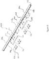
- FIG. 3 of the drawings there is illustrated a frame assembly 100, in a partially configured arrangement.
- Three frame members 101a,101b,101c are shown in a joined configuration.
- a plurality of first fixing members 110 are shown extending through the plurality of apertures 105 on the frame member casings and into the insert, which is not visible being within the internal channel, thereby connecting the frame members and insert.
- a plurality of second fixing members 120 is disposed within the external channel 104 of the frame members is visible.
- a plate 140 is shown which is disposable within the external channel 104. The plate has a plurality of first plate apertures 142 alignable with the plurality of second fixing members 120 in use.
- the plate 140 enters into the channel 104 and the plurality of second fixing members 120 extend through the first plate apertures 142.
- the first fixing means or members 110 as shown comprises a threaded bolt 110a and a washer 110b, the washer being placed between the bolt and the surface of the external channel 104.
- the second fixing means or members 120 as shown comprises a threaded bolt 120, a nut 121a and washer 121b, in use the bolt 120 protrudes through aperture 142 of the plate 140; the washer 121b is between the plate and nut 121a.
- both the first and second fixing means are shown as threaded bolts, included nuts (for the second means) and washers. It will be appreciated that the skilled person could consider various other attachment means for example but not limited to clips, brackets, screws, adhesives, resiliently deformable members, straps etc.
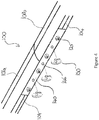
- FIG. 4 of the drawings there is illustrated a frame assembly 100, in an assembly arrangement.
- Two frame members 101a,101b are shown in a joined configuration, by the plate 140 located in the external channel 104, secured to both the frame members by fixing means 120. Further shown is the plate 140 has a second plurality of apertures 146 configured to receive a connection means 150 for supporting a goal net 207.
- the components can be brought to the location of the goal in a deconstructed configuration.
- Two frame members 101a and 101b may be set out with an insert 130.
- the insert 130 is placed partially within both the internal channels 103 of the frame members, there may be locating feature within the channel to help with alignment.
- Second fixing members 120 are slid into the external channel 104, which may also have locating features to help with alignment.
- the frame members are brought together and the insert 130 enclosed.
- the second fixing members protrude outwards from the external channel.
- First fixing members 110 are placed through apertures 105 in the external channel 104 into the internal channel 103 and also the insert 130, thereby retaining the insert within the frame members and also securing the opposing frame members 101a,101b.
- a plate 140 is placed over the protruding second fixing members 120, which extend through the plates first apertures 142. Additional features of the fixing members 120 such as washers 121b and nuts 121a can then be used to secure the plate in place and further securing the frame members, such that they are adequately robust for use. Finally further connecting means 150 can be placed through the plate's 140 second plate apertures 146, which can be used to attach the net 207 to the goal. Once the frame assembly is completed it can be attached to further interconnectable modular frame assemblies or standard components to form the full structure of a goal 10. Multiple frame assemblies can be used to create multiple goals at different location with ease.
- frame assembly of the present invention provides a modular, safe and portable goal for use in all weather conditions, conforming to all the required safety standards and meeting different sporting regulations.
Landscapes
- Engineering & Computer Science (AREA)
- General Engineering & Computer Science (AREA)
- Health & Medical Sciences (AREA)
- General Health & Medical Sciences (AREA)
- Physical Education & Sports Medicine (AREA)
- Mechanical Engineering (AREA)
- Mutual Connection Of Rods And Tubes (AREA)
Description
- The present invention relates to crossbars for sports goals and like assemblies, and more particularly, to modular crossbars for portable or semi-permanent football goals.
- It is important to allow sports goals to be easily accessible around the world without compromising on their safety and durability. Goals are used for many different sports including but not limited to football, handball and futsal.
- On existing, conventional models the logistical and conceptual design of a crossbar is inefficient due to the size, weight and manufacturing processes put into place. As a result, the restriction placed upon the size and weight of the crossbar further enhances the restricted access for the end consumer due to increased logistical outlay and assembly time.
- The traditional crossbar design is uninspired, bulky and not fit for the modern era whereby increased consumer demand requires faster delivery times allowing soccer goals to be introduced into the mass market bringing an enhanced user-friendly design. Lifting and lowering of the crossbar needs to be done in a safe manner and involve the minimum number of operators possible. All these need to be overcome whilst still meeting strict safety standards.
-
US2007/145688 discloses a connector and goal frame member comprising an elongate goal frame member with a hollow open end and a connector slidably received with the hollow end, and a fastener extending through a recessed channel of the goal frame member and an inset track of the connector. -
EP3053631 discloses an aluminium profile joining corner element for a goal frame, the corner element comprising a corner housing surrounding a corner tube.JP2010227192 - To overcome issues with the prior art, the present invention proposes an aluminium crossbar on a modular mechanism that is easy to assemble using brackets and internal connectors, this is done in a manner which does not have any fittings or fixings protruding from the face of the goal whilst also allowing net clips to still be fitted into the fixing channel. The crossbar, which can be fitted to numerous sizes of sports goals, enables the efficient construction of the goal whilst deploying a safe, sturdy and non-corrosive crossbar. The crossbar is also locked into place with specifically designed hardware to enable a singular person to assemble the goal whilst reducing the minimum number of operators required for lifting and carrying.
- In accordance with the present invention there is provided a frame assembly for a sports goal comprising:
- at least two frame members each comprising an internal channel defined by a respective frame member casing and each comprising an external channel formed upon the casing;
wherein each frame member casing comprises a plurality of apertures extending between the internal channel and external channel channel; - an insert disposed within the internal channel of each of the at least two frame members in use, the insert having a plurality of insert apertures, each of the plurality of insert apertures being aligned in use with a corresponding aperture of the frame member casings; and
- a plurality of first fixing members, each first fixing member being configured to extend in use through one of the plurality of apertures of the frame member casings and the corresponding insert aperture with which the aperture of the frame member casing is aligned when the insert apertures and the apertures of the frame member casings are aligned in use, the plurality of first fixing members extending between the internal channel and the external channel of the frame members is use and thereby connecting the at least two frame members and the insert;
- characterised by a plurality of second fixing members, each of which is disposed in use within one of the external channels of the at least two the frame members to protrude outwardly from said external channel in use; and
- a plate, disposed within the external channel of each of the at least two frame members in use, the plate having a plurality of first plate apertures, each aperture being aligned in use with a corresponding one of the second fixing members which extends in use through the first plate aperture with which it is aligned, thereby connecting the plate to the frame members, the plate having the plate having a plurality of second plate apertures configured to receive a connection means for connecting a goal net to the frame assembly.
- The invention differs from the prior art, in particular
US2007/145688 , in its characterising features. - Further aspects and embodiments of the invention are provided as set out in the claims.
- The invention may be performed in various ways and embodiments thereof will now be described, by way of example only, reference being made to the accompanying drawings, in which:
-
Figure 1 is a diagram showing an exemplary sports goal using the frame assembly according to an embodiment of the invention; -
Figure 2 is a diagram showing an unassembled view of components of the frame assembly according to an embodiment of the invention; -
Figure 3 is a diagram showing a partially assembled view of components of the frame assembly according to an embodiment of the invention; and, -
Figure 4 is a diagram showing an assembled view of components of the frame assembly according to an embodiment of the invention. - Referring to
Figure 1 of the drawings, there is illustrated a sports goal 10 for use in football (soccer) comprising aframe assembly 100 according to an embodiment of the present invention. Theframe assembly 100 comprises threeframe members plates 140, situated in anexternal channel 104 formed on the rear in use of the casing of the frame members. The plates are attached to the frame member withfixing members 120. The three frame members are connected viajoints 202 to theupright posts 203, which in turn are connected toside posts 204. Asecond base crossbar 200 potentially identical to theupper crossbar 100 is placed to the rear between theside posts 204. A back ornet support 205 is connected between the joints of the upper and base crossbars. Additionallybracers 206 are placed at the corner to further support the net 207 and the goal frame 10. - In an embodiment the frame members are tubular. The frame members may be partly, substantially hollow. The frame members may adhere to standard or conventional shapes and sizes of sports goals components, such that they may be retrofitted to existing goals or form new modular assemblies where more than one is used. The frame member may be constructed from any appropriate material such as aluminium or plastics.
- Referring to
Figure 2 of the drawings, there is illustrated a portion of aframe assembly 100, prior to it being assembled for use. Twoframe members insert 130 is shown between the two frame members. Theinsert 130 is positionable within theinternal channel 103 of the frame members. Theinsert 130 hasapertures 135 which align withapertures 105 on the casing of the frame member extending between theexternal channel 104 and theinternal channel 103. When the two frame members 101 are connected such that they are abutting, theinsert 130 will not be visible. Further shown are fixingmembers 120 which slot into theexternal channel 103, which will be used for attaching further components to the assembly. - In an embodiment the insert is weighted to weigh down the goal to prevent any injury from tipping. The insert may be aligned within the frame members with the help of locating features within the internal channel; such features may be protrusions which impede further progress along the length of the member or the like. In conjunction with the frame members the insert may be constructed from various materials in the appropriate size and shape for the required use.
- In an embodiment the external channel is as known in the art, profiled such that the channel may be used with "quick clips" to attach nets to goals. Further embodiments are envisaged where the channel also cooperates with
second fixing members 120 to retain them in place, the channel may be further supplied with locating features such as protrusions or indentations that the fixing member cooperate with. InFigure 2 the fixing member is a threaded bolt, where the bolt locates in the channel. It will be appreciated that the skilled person could envisage multiple various method of attachment that are simple and well know. For example theinsert aperture 135 may include a threaded circumference or other method to retain thefirst fixing means 110. - Referring to
Figure 3 of the drawings, there is illustrated aframe assembly 100, in a partially configured arrangement. Threeframe members first fixing members 110 are shown extending through the plurality ofapertures 105 on the frame member casings and into the insert, which is not visible being within the internal channel, thereby connecting the frame members and insert. A plurality ofsecond fixing members 120 is disposed within theexternal channel 104 of the frame members is visible. Aplate 140 is shown which is disposable within theexternal channel 104. The plate has a plurality offirst plate apertures 142 alignable with the plurality ofsecond fixing members 120 in use. It can be seen that theplate 140 enters into thechannel 104 and the plurality ofsecond fixing members 120 extend through thefirst plate apertures 142. When the plate is in the channel and engaged with the second fixing members the connection between the frame members is further secured. The first fixing means ormembers 110 as shown comprises a threaded bolt 110a and a washer 110b, the washer being placed between the bolt and the surface of theexternal channel 104. The second fixing means ormembers 120 as shown comprises a threadedbolt 120, a nut 121a and washer 121b, in use thebolt 120 protrudes throughaperture 142 of theplate 140; the washer 121b is between the plate and nut 121a. - In an embodiment both the first and second fixing means are shown as threaded bolts, included nuts (for the second means) and washers. It will be appreciated that the skilled person could consider various other attachment means for example but not limited to clips, brackets, screws, adhesives, resiliently deformable members, straps etc.
- Referring to
Figure 4 of the drawings, there is illustrated aframe assembly 100, in an assembly arrangement. Twoframe members plate 140 located in theexternal channel 104, secured to both the frame members by fixingmeans 120. Further shown is theplate 140 has a second plurality ofapertures 146 configured to receive a connection means 150 for supporting agoal net 207. - In an example of use of the
frame assembly 100, the components can be brought to the location of the goal in a deconstructed configuration. Twoframe members insert 130. Theinsert 130 is placed partially within both theinternal channels 103 of the frame members, there may be locating feature within the channel to help with alignment. Second fixingmembers 120 are slid into theexternal channel 104, which may also have locating features to help with alignment. The frame members are brought together and theinsert 130 enclosed. The second fixing members protrude outwards from the external channel. First fixingmembers 110 are placed throughapertures 105 in theexternal channel 104 into theinternal channel 103 and also theinsert 130, thereby retaining the insert within the frame members and also securing the opposingframe members plate 140 is placed over the protruding second fixingmembers 120, which extend through the platesfirst apertures 142. Additional features of the fixingmembers 120 such as washers 121b and nuts 121a can then be used to secure the plate in place and further securing the frame members, such that they are adequately robust for use. Finally further connectingmeans 150 can be placed through the plate's 140second plate apertures 146, which can be used to attach the net 207 to the goal. Once the frame assembly is completed it can be attached to further interconnectable modular frame assemblies or standard components to form the full structure of a goal 10. Multiple frame assemblies can be used to create multiple goals at different location with ease. - It will be appreciated that some of these steps can be done in different orders, for example sliding in the second fixing members from the end of the channel furthest from where the members connect, but this will add time to the set up.
- It will be appreciated that frame assembly of the present invention provides a modular, safe and portable goal for use in all weather conditions, conforming to all the required safety standards and meeting different sporting regulations.
Claims (8)
- A frame assembly (100) for a sports goal comprising:at least two frame members (101) each comprising an internal channel (103) defined by a respective frame member casing and each comprising an external channel (104) formed upon the casing;
wherein each frame member casing comprises a plurality of apertures (105) extending between the internal channel (103) and external channel (104);an insert (130) disposed within the internal channel (103) of each of the at least two frame members in use, the insert having a plurality of insert apertures (135);each of the plurality of insert apertures (135) being aligned in use with a corresponding aperture (105) of the frame member casings; anda plurality of first fixing members (110), each first fixing member being configured to extend in use through one of the plurality of apertures (105) of the frame member casings and the corresponding insert aperture (135) with which the aperture (105) of the frame member casing is aligned when the insert apertures (135) and the apertures (105) of the frame member casings are aligned in use, the plurality of first fixing members extending between the internal channel (103) and the external channel (104) of the frame members in use and thereby connecting the at least two frame members and the insert;characterised by:a plurality of second fixing members (120), each of which is disposed in use within one of the external channels (104) of the at least two frame members to protrude outwardly from said external channel in use; anda plate (140), disposed within the external channel of each of the at least two frame members (104) in use, the plate having a plurality of first plate apertures (142), each aperture (142) being aligned in use with a corresponding one of the second fixing members (120) which extends in use through the first plate aperture (140) with which it is aligned thereby connecting the plate (140) to the frame members, the plate having a plurality of second plate apertures (146), each second plate aperture being configured to receive a connection means for connecting a goal net to the frame assembly. - A frame assembly as claimed in claim 1, wherein the frame members (101) are substantially tubular in shape.
- A frame assembly as claimed in any previous claim, comprising three frame members and two inserts.
- A frame assembly as claimed in any previous claim, wherein the insert (130) comprise an internal thread formed within the apertures (135) which is engagable with the plurality of first fixing members (110).
- A frame assembly as claimed in any previous claim, wherein the plurality of second fixing members (120) each comprise a bolt, washer (121b) and nut (121a).
- A frame assembly as claimed in any previous claim, further comprising joint members (202) to connect the frame members (101) to further frame components (203).
- A sports goal comprising a frame assembly as claimed in any previous claim.
- A sports goal as claimed in claim 7 wherein the sports goal is for football, footsal or handball.
Applications Claiming Priority (1)
| Application Number | Priority Date | Filing Date | Title |
|---|---|---|---|
| GB1817829.3A GB2578612B (en) | 2018-10-31 | 2018-10-31 | Modular crossbar |
Publications (2)
| Publication Number | Publication Date |
|---|---|
| EP3653273A1 EP3653273A1 (en) | 2020-05-20 |
| EP3653273B1 true EP3653273B1 (en) | 2021-12-08 |
Family
ID=64655651
Family Applications (1)
| Application Number | Title | Priority Date | Filing Date |
|---|---|---|---|
| EP19205929.3A Revoked EP3653273B1 (en) | 2018-10-31 | 2019-10-29 | Modular crossbar |
Country Status (5)
| Country | Link |
|---|---|
| US (1) | US20200129826A1 (en) |
| EP (1) | EP3653273B1 (en) |
| AU (1) | AU2019257411A1 (en) |
| ES (1) | ES2908404T3 (en) |
| GB (1) | GB2578612B (en) |
Families Citing this family (2)
| Publication number | Priority date | Publication date | Assignee | Title |
|---|---|---|---|---|
| USD1101882S1 (en) * | 2022-02-09 | 2025-11-11 | Soccer Park, LLC | Futsal goal |
| US20240322749A1 (en) * | 2023-03-20 | 2024-09-26 | Greenec Corp. | Rail fixing assembly |
Family Cites Families (5)
| Publication number | Priority date | Publication date | Assignee | Title |
|---|---|---|---|---|
| JP4084698B2 (en) * | 2003-04-25 | 2008-04-30 | 日軽金アクト株式会社 | Ball goal |
| US7300059B2 (en) * | 2005-12-28 | 2007-11-27 | Kwik Goal Ltd. | Connector for sports goal frame |
| JP5281454B2 (en) * | 2009-03-26 | 2013-09-04 | 日軽金アクト株式会社 | Ball goal |
| NO344312B1 (en) * | 2014-12-04 | 2019-11-04 | Unisport Scandinavia As | An aluminum profile-splicing corner element and a ball game target with such elements |
| CN107349580A (en) * | 2017-08-10 | 2017-11-17 | 江苏金陵体育器材股份有限公司 | Football door frame |
-
2018
- 2018-10-31 GB GB1817829.3A patent/GB2578612B/en active Active
-
2019
- 2019-10-29 ES ES19205929T patent/ES2908404T3/en active Active
- 2019-10-29 EP EP19205929.3A patent/EP3653273B1/en not_active Revoked
- 2019-10-29 AU AU2019257411A patent/AU2019257411A1/en not_active Abandoned
- 2019-10-30 US US16/668,741 patent/US20200129826A1/en not_active Abandoned
Non-Patent Citations (1)
| Title |
|---|
| None * |
Also Published As
| Publication number | Publication date |
|---|---|
| US20200129826A1 (en) | 2020-04-30 |
| ES2908404T3 (en) | 2022-04-29 |
| GB2578612B (en) | 2020-11-18 |
| GB2578612A (en) | 2020-05-20 |
| EP3653273A1 (en) | 2020-05-20 |
| AU2019257411A1 (en) | 2020-05-14 |
| GB201817829D0 (en) | 2018-12-19 |
Similar Documents
| Publication | Publication Date | Title |
|---|---|---|
| US8206270B2 (en) | Apparatus and method for temporary mounting of a hangboard | |
| US20120241570A1 (en) | Apparatus and Method for Temporary Mounting of a Hangboard | |
| US9275565B2 (en) | Jersey hanger assembly and jersey display | |
| US9550085B2 (en) | Swingset suspension | |
| US20180147434A1 (en) | Trampoline with full enclosure system | |
| US20130184124A1 (en) | Portable modular hanging and pulling system | |
| US10507349B2 (en) | Exercise frame system | |
| US8715116B2 (en) | Collapsible, portable sport goal | |
| EP3653273A1 (en) | Modular crossbar | |
| CA2799522A1 (en) | Brackets and bracket system for assembling playground equipment | |
| EP3847377A1 (en) | Modular furniture with tool free assembly | |
| US11865399B2 (en) | Mobile outdoor gym and resistance weight training equipment | |
| US5782526A (en) | Leg assembly for a table | |
| RU2600805C2 (en) | Bearing frame with connection assemblies | |
| US7419457B1 (en) | Climbing wall assembly | |
| AU649244B2 (en) | Sports equipment | |
| US9986834B1 (en) | Structure of reception chair | |
| CN101351247B (en) | Multifunctional prefabricated sporting goods | |
| KR20100011293A (en) | Prefabricated structure | |
| US10406418B2 (en) | Device to attach climbing hold to fence | |
| KR101849108B1 (en) | Safety fence for work place | |
| CA2618262A1 (en) | Portable screen system | |
| WO1993025285A2 (en) | Portable goalpost | |
| KR101483359B1 (en) | boxing ring | |
| KR200322374Y1 (en) | Recreation facility using double air mat |
Legal Events
| Date | Code | Title | Description |
|---|---|---|---|
| PUAI | Public reference made under article 153(3) epc to a published international application that has entered the european phase |
Free format text: ORIGINAL CODE: 0009012 |
|
| STAA | Information on the status of an ep patent application or granted ep patent |
Free format text: STATUS: THE APPLICATION HAS BEEN PUBLISHED |
|
| AK | Designated contracting states |
Kind code of ref document: A1 Designated state(s): AL AT BE BG CH CY CZ DE DK EE ES FI FR GB GR HR HU IE IS IT LI LT LU LV MC MK MT NL NO PL PT RO RS SE SI SK SM TR |
|
| AX | Request for extension of the european patent |
Extension state: BA ME |
|
| STAA | Information on the status of an ep patent application or granted ep patent |
Free format text: STATUS: REQUEST FOR EXAMINATION WAS MADE |
|
| 17P | Request for examination filed |
Effective date: 20200612 |
|
| RBV | Designated contracting states (corrected) |
Designated state(s): AL AT BE BG CH CY CZ DE DK EE ES FI FR GB GR HR HU IE IS IT LI LT LU LV MC MK MT NL NO PL PT RO RS SE SI SK SM TR |
|
| STAA | Information on the status of an ep patent application or granted ep patent |
Free format text: STATUS: EXAMINATION IS IN PROGRESS |
|
| 17Q | First examination report despatched |
Effective date: 20201112 |
|
| RIC1 | Information provided on ipc code assigned before grant |
Ipc: A63B 63/00 20060101AFI20210503BHEP Ipc: F16B 12/40 20060101ALI20210503BHEP Ipc: E04B 1/58 20060101ALI20210503BHEP Ipc: F16B 2/22 20060101ALI20210503BHEP Ipc: F16B 5/06 20060101ALI20210503BHEP Ipc: F16B 7/04 20060101ALI20210503BHEP Ipc: F16B 7/18 20060101ALI20210503BHEP |
|
| GRAP | Despatch of communication of intention to grant a patent |
Free format text: ORIGINAL CODE: EPIDOSNIGR1 |
|
| STAA | Information on the status of an ep patent application or granted ep patent |
Free format text: STATUS: GRANT OF PATENT IS INTENDED |
|
| INTG | Intention to grant announced |
Effective date: 20210621 |
|
| GRAS | Grant fee paid |
Free format text: ORIGINAL CODE: EPIDOSNIGR3 |
|
| GRAA | (expected) grant |
Free format text: ORIGINAL CODE: 0009210 |
|
| STAA | Information on the status of an ep patent application or granted ep patent |
Free format text: STATUS: THE PATENT HAS BEEN GRANTED |
|
| AK | Designated contracting states |
Kind code of ref document: B1 Designated state(s): AL AT BE BG CH CY CZ DE DK EE ES FI FR GB GR HR HU IE IS IT LI LT LU LV MC MK MT NL NO PL PT RO RS SE SI SK SM TR |
|
| REG | Reference to a national code |
Ref country code: GB Ref legal event code: FG4D |
|
| REG | Reference to a national code |
Ref country code: AT Ref legal event code: REF Ref document number: 1453308 Country of ref document: AT Kind code of ref document: T Effective date: 20211215 Ref country code: CH Ref legal event code: EP |
|
| REG | Reference to a national code |
Ref country code: DE Ref legal event code: R096 Ref document number: 602019009900 Country of ref document: DE |
|
| REG | Reference to a national code |
Ref country code: IE Ref legal event code: FG4D |
|
| REG | Reference to a national code |
Ref country code: DE Ref legal event code: R026 Ref document number: 602019009900 Country of ref document: DE |
|
| PLBI | Opposition filed |
Free format text: ORIGINAL CODE: 0009260 |
|
| 26 | Opposition filed |
Opponent name: PMF PRODUCTS LTD Effective date: 20220224 |
|
| REG | Reference to a national code |
Ref country code: LT Ref legal event code: MG9D |
|
| REG | Reference to a national code |
Ref country code: NL Ref legal event code: MP Effective date: 20211208 |
|
| PG25 | Lapsed in a contracting state [announced via postgrant information from national office to epo] |
Ref country code: RS Free format text: LAPSE BECAUSE OF FAILURE TO SUBMIT A TRANSLATION OF THE DESCRIPTION OR TO PAY THE FEE WITHIN THE PRESCRIBED TIME-LIMIT Effective date: 20211208 Ref country code: LT Free format text: LAPSE BECAUSE OF FAILURE TO SUBMIT A TRANSLATION OF THE DESCRIPTION OR TO PAY THE FEE WITHIN THE PRESCRIBED TIME-LIMIT Effective date: 20211208 Ref country code: FI Free format text: LAPSE BECAUSE OF FAILURE TO SUBMIT A TRANSLATION OF THE DESCRIPTION OR TO PAY THE FEE WITHIN THE PRESCRIBED TIME-LIMIT Effective date: 20211208 Ref country code: BG Free format text: LAPSE BECAUSE OF FAILURE TO SUBMIT A TRANSLATION OF THE DESCRIPTION OR TO PAY THE FEE WITHIN THE PRESCRIBED TIME-LIMIT Effective date: 20220308 |
|
| REG | Reference to a national code |
Ref country code: ES Ref legal event code: FG2A Ref document number: 2908404 Country of ref document: ES Kind code of ref document: T3 Effective date: 20220429 |
|
| REG | Reference to a national code |
Ref country code: AT Ref legal event code: MK05 Ref document number: 1453308 Country of ref document: AT Kind code of ref document: T Effective date: 20211208 |
|
| PG25 | Lapsed in a contracting state [announced via postgrant information from national office to epo] |
Ref country code: SE Free format text: LAPSE BECAUSE OF FAILURE TO SUBMIT A TRANSLATION OF THE DESCRIPTION OR TO PAY THE FEE WITHIN THE PRESCRIBED TIME-LIMIT Effective date: 20211208 Ref country code: NO Free format text: LAPSE BECAUSE OF FAILURE TO SUBMIT A TRANSLATION OF THE DESCRIPTION OR TO PAY THE FEE WITHIN THE PRESCRIBED TIME-LIMIT Effective date: 20220308 Ref country code: LV Free format text: LAPSE BECAUSE OF FAILURE TO SUBMIT A TRANSLATION OF THE DESCRIPTION OR TO PAY THE FEE WITHIN THE PRESCRIBED TIME-LIMIT Effective date: 20211208 Ref country code: HR Free format text: LAPSE BECAUSE OF FAILURE TO SUBMIT A TRANSLATION OF THE DESCRIPTION OR TO PAY THE FEE WITHIN THE PRESCRIBED TIME-LIMIT Effective date: 20211208 Ref country code: GR Free format text: LAPSE BECAUSE OF FAILURE TO SUBMIT A TRANSLATION OF THE DESCRIPTION OR TO PAY THE FEE WITHIN THE PRESCRIBED TIME-LIMIT Effective date: 20220309 |
|
| PG25 | Lapsed in a contracting state [announced via postgrant information from national office to epo] |
Ref country code: NL Free format text: LAPSE BECAUSE OF FAILURE TO SUBMIT A TRANSLATION OF THE DESCRIPTION OR TO PAY THE FEE WITHIN THE PRESCRIBED TIME-LIMIT Effective date: 20211208 |
|
| PG25 | Lapsed in a contracting state [announced via postgrant information from national office to epo] |
Ref country code: SM Free format text: LAPSE BECAUSE OF FAILURE TO SUBMIT A TRANSLATION OF THE DESCRIPTION OR TO PAY THE FEE WITHIN THE PRESCRIBED TIME-LIMIT Effective date: 20211208 Ref country code: SK Free format text: LAPSE BECAUSE OF FAILURE TO SUBMIT A TRANSLATION OF THE DESCRIPTION OR TO PAY THE FEE WITHIN THE PRESCRIBED TIME-LIMIT Effective date: 20211208 Ref country code: RO Free format text: LAPSE BECAUSE OF FAILURE TO SUBMIT A TRANSLATION OF THE DESCRIPTION OR TO PAY THE FEE WITHIN THE PRESCRIBED TIME-LIMIT Effective date: 20211208 Ref country code: PT Free format text: LAPSE BECAUSE OF FAILURE TO SUBMIT A TRANSLATION OF THE DESCRIPTION OR TO PAY THE FEE WITHIN THE PRESCRIBED TIME-LIMIT Effective date: 20220408 Ref country code: EE Free format text: LAPSE BECAUSE OF FAILURE TO SUBMIT A TRANSLATION OF THE DESCRIPTION OR TO PAY THE FEE WITHIN THE PRESCRIBED TIME-LIMIT Effective date: 20211208 Ref country code: CZ Free format text: LAPSE BECAUSE OF FAILURE TO SUBMIT A TRANSLATION OF THE DESCRIPTION OR TO PAY THE FEE WITHIN THE PRESCRIBED TIME-LIMIT Effective date: 20211208 |
|
| PG25 | Lapsed in a contracting state [announced via postgrant information from national office to epo] |
Ref country code: PL Free format text: LAPSE BECAUSE OF FAILURE TO SUBMIT A TRANSLATION OF THE DESCRIPTION OR TO PAY THE FEE WITHIN THE PRESCRIBED TIME-LIMIT Effective date: 20211208 Ref country code: AT Free format text: LAPSE BECAUSE OF FAILURE TO SUBMIT A TRANSLATION OF THE DESCRIPTION OR TO PAY THE FEE WITHIN THE PRESCRIBED TIME-LIMIT Effective date: 20211208 |
|
| PLAX | Notice of opposition and request to file observation + time limit sent |
Free format text: ORIGINAL CODE: EPIDOSNOBS2 |
|
| PG25 | Lapsed in a contracting state [announced via postgrant information from national office to epo] |
Ref country code: IS Free format text: LAPSE BECAUSE OF FAILURE TO SUBMIT A TRANSLATION OF THE DESCRIPTION OR TO PAY THE FEE WITHIN THE PRESCRIBED TIME-LIMIT Effective date: 20220408 |
|
| PG25 | Lapsed in a contracting state [announced via postgrant information from national office to epo] |
Ref country code: DK Free format text: LAPSE BECAUSE OF FAILURE TO SUBMIT A TRANSLATION OF THE DESCRIPTION OR TO PAY THE FEE WITHIN THE PRESCRIBED TIME-LIMIT Effective date: 20211208 Ref country code: AL Free format text: LAPSE BECAUSE OF FAILURE TO SUBMIT A TRANSLATION OF THE DESCRIPTION OR TO PAY THE FEE WITHIN THE PRESCRIBED TIME-LIMIT Effective date: 20211208 |
|
| PG25 | Lapsed in a contracting state [announced via postgrant information from national office to epo] |
Ref country code: SI Free format text: LAPSE BECAUSE OF FAILURE TO SUBMIT A TRANSLATION OF THE DESCRIPTION OR TO PAY THE FEE WITHIN THE PRESCRIBED TIME-LIMIT Effective date: 20211208 |
|
| PGFP | Annual fee paid to national office [announced via postgrant information from national office to epo] |
Ref country code: FR Payment date: 20221020 Year of fee payment: 4 |
|
| PGFP | Annual fee paid to national office [announced via postgrant information from national office to epo] |
Ref country code: ES Payment date: 20221118 Year of fee payment: 4 Ref country code: DE Payment date: 20221020 Year of fee payment: 4 |
|
| RDAF | Communication despatched that patent is revoked |
Free format text: ORIGINAL CODE: EPIDOSNREV1 |
|
| REG | Reference to a national code |
Ref country code: DE Ref legal event code: R103 Ref document number: 602019009900 Country of ref document: DE Ref country code: DE Ref legal event code: R064 Ref document number: 602019009900 Country of ref document: DE |
|
| PG25 | Lapsed in a contracting state [announced via postgrant information from national office to epo] |
Ref country code: MC Free format text: LAPSE BECAUSE OF FAILURE TO SUBMIT A TRANSLATION OF THE DESCRIPTION OR TO PAY THE FEE WITHIN THE PRESCRIBED TIME-LIMIT Effective date: 20211208 Ref country code: IT Free format text: LAPSE BECAUSE OF FAILURE TO SUBMIT A TRANSLATION OF THE DESCRIPTION OR TO PAY THE FEE WITHIN THE PRESCRIBED TIME-LIMIT Effective date: 20211208 |
|
| REG | Reference to a national code |
Ref country code: CH Ref legal event code: PL |
|
| REG | Reference to a national code |
Ref country code: BE Ref legal event code: MM Effective date: 20221031 |
|
| PG25 | Lapsed in a contracting state [announced via postgrant information from national office to epo] |
Ref country code: LU Free format text: LAPSE BECAUSE OF NON-PAYMENT OF DUE FEES Effective date: 20221029 |
|
| PG25 | Lapsed in a contracting state [announced via postgrant information from national office to epo] |
Ref country code: LI Free format text: LAPSE BECAUSE OF NON-PAYMENT OF DUE FEES Effective date: 20221031 Ref country code: CH Free format text: LAPSE BECAUSE OF NON-PAYMENT OF DUE FEES Effective date: 20221031 |
|
| RDAG | Patent revoked |
Free format text: ORIGINAL CODE: 0009271 |
|
| STAA | Information on the status of an ep patent application or granted ep patent |
Free format text: STATUS: PATENT REVOKED |
|
| REG | Reference to a national code |
Ref country code: CH Ref legal event code: PL |
|
| PG25 | Lapsed in a contracting state [announced via postgrant information from national office to epo] |
Ref country code: BE Free format text: LAPSE BECAUSE OF NON-PAYMENT OF DUE FEES Effective date: 20221031 |
|
| 27W | Patent revoked |
Effective date: 20230529 |
|
| GBPR | Gb: patent revoked under art. 102 of the ep convention designating the uk as contracting state |
Effective date: 20230529 |
|
| PG25 | Lapsed in a contracting state [announced via postgrant information from national office to epo] |
Ref country code: CY Free format text: LAPSE BECAUSE OF FAILURE TO SUBMIT A TRANSLATION OF THE DESCRIPTION OR TO PAY THE FEE WITHIN THE PRESCRIBED TIME-LIMIT Effective date: 20211208 |
|
| PG25 | Lapsed in a contracting state [announced via postgrant information from national office to epo] |
Ref country code: MK Free format text: LAPSE BECAUSE OF FAILURE TO SUBMIT A TRANSLATION OF THE DESCRIPTION OR TO PAY THE FEE WITHIN THE PRESCRIBED TIME-LIMIT Effective date: 20211208 |
|
| PG25 | Lapsed in a contracting state [announced via postgrant information from national office to epo] |
Ref country code: IE Free format text: LAPSE BECAUSE OF NON-PAYMENT OF DUE FEES Effective date: 20221029 |
|
| PG25 | Lapsed in a contracting state [announced via postgrant information from national office to epo] |
Ref country code: IE Free format text: LAPSE BECAUSE OF NON-PAYMENT OF DUE FEES Effective date: 20221029 |
|
| PG25 | Lapsed in a contracting state [announced via postgrant information from national office to epo] |
Ref country code: HU Free format text: LAPSE BECAUSE OF FAILURE TO SUBMIT A TRANSLATION OF THE DESCRIPTION OR TO PAY THE FEE WITHIN THE PRESCRIBED TIME-LIMIT; INVALID AB INITIO Effective date: 20191029 |
|
| PG25 | Lapsed in a contracting state [announced via postgrant information from national office to epo] |
Ref country code: MT Free format text: LAPSE BECAUSE OF FAILURE TO SUBMIT A TRANSLATION OF THE DESCRIPTION OR TO PAY THE FEE WITHIN THE PRESCRIBED TIME-LIMIT Effective date: 20211208 |
|
| PG25 | Lapsed in a contracting state [announced via postgrant information from national office to epo] |
Ref country code: TR Free format text: LAPSE BECAUSE OF FAILURE TO SUBMIT A TRANSLATION OF THE DESCRIPTION OR TO PAY THE FEE WITHIN THE PRESCRIBED TIME-LIMIT Effective date: 20211208 |