EP3053631A1 - An aluminium section joining corner element and a goal for ball games with such elements - Google Patents
An aluminium section joining corner element and a goal for ball games with such elements Download PDFInfo
- Publication number
- EP3053631A1 EP3053631A1 EP15197432.6A EP15197432A EP3053631A1 EP 3053631 A1 EP3053631 A1 EP 3053631A1 EP 15197432 A EP15197432 A EP 15197432A EP 3053631 A1 EP3053631 A1 EP 3053631A1
- Authority
- EP
- European Patent Office
- Prior art keywords
- corner
- substantially straight
- tubular element
- aluminum profile
- straight tubular
- Prior art date
- Legal status (The legal status is an assumption and is not a legal conclusion. Google has not performed a legal analysis and makes no representation as to the accuracy of the status listed.)
- Granted
Links
- 229910052782 aluminium Inorganic materials 0.000 title claims abstract description 81
- XAGFODPZIPBFFR-UHFFFAOYSA-N aluminium Chemical compound [Al] XAGFODPZIPBFFR-UHFFFAOYSA-N 0.000 title claims abstract description 81
- 239000004411 aluminium Substances 0.000 title description 2
- 239000000463 material Substances 0.000 claims description 17
- 229910052751 metal Inorganic materials 0.000 claims description 4
- 239000002184 metal Substances 0.000 claims description 4
- 239000012777 electrically insulating material Substances 0.000 claims description 2
- 229910000831 Steel Inorganic materials 0.000 description 10
- 239000010959 steel Substances 0.000 description 10
- 230000007797 corrosion Effects 0.000 description 7
- 238000005260 corrosion Methods 0.000 description 7
- 239000010935 stainless steel Substances 0.000 description 6
- 229910001220 stainless steel Inorganic materials 0.000 description 6
- 238000009413 insulation Methods 0.000 description 3
- 230000003014 reinforcing effect Effects 0.000 description 3
- 229910001335 Galvanized steel Inorganic materials 0.000 description 1
- 238000005452 bending Methods 0.000 description 1
- 239000008397 galvanized steel Substances 0.000 description 1
- 239000012774 insulation material Substances 0.000 description 1
- 238000004519 manufacturing process Methods 0.000 description 1
- 230000007704 transition Effects 0.000 description 1
Images



Classifications
-
- A—HUMAN NECESSITIES
- A63—SPORTS; GAMES; AMUSEMENTS
- A63B—APPARATUS FOR PHYSICAL TRAINING, GYMNASTICS, SWIMMING, CLIMBING, OR FENCING; BALL GAMES; TRAINING EQUIPMENT
- A63B63/00—Targets or goals for ball games
- A63B63/004—Goals of the type used for football, handball, hockey or the like
-
- F—MECHANICAL ENGINEERING; LIGHTING; HEATING; WEAPONS; BLASTING
- F16—ENGINEERING ELEMENTS AND UNITS; GENERAL MEASURES FOR PRODUCING AND MAINTAINING EFFECTIVE FUNCTIONING OF MACHINES OR INSTALLATIONS; THERMAL INSULATION IN GENERAL
- F16B—DEVICES FOR FASTENING OR SECURING CONSTRUCTIONAL ELEMENTS OR MACHINE PARTS TOGETHER, e.g. NAILS, BOLTS, CIRCLIPS, CLAMPS, CLIPS OR WEDGES; JOINTS OR JOINTING
- F16B12/00—Jointing of furniture or the like, e.g. hidden from exterior
- F16B12/40—Joints for furniture tubing
-
- A—HUMAN NECESSITIES
- A63—SPORTS; GAMES; AMUSEMENTS
- A63B—APPARATUS FOR PHYSICAL TRAINING, GYMNASTICS, SWIMMING, CLIMBING, OR FENCING; BALL GAMES; TRAINING EQUIPMENT
- A63B2209/00—Characteristics of used materials
-
- A—HUMAN NECESSITIES
- A63—SPORTS; GAMES; AMUSEMENTS
- A63B—APPARATUS FOR PHYSICAL TRAINING, GYMNASTICS, SWIMMING, CLIMBING, OR FENCING; BALL GAMES; TRAINING EQUIPMENT
- A63B2210/00—Space saving
- A63B2210/50—Size reducing arrangements for stowing or transport
-
- E—FIXED CONSTRUCTIONS
- E04—BUILDING
- E04B—GENERAL BUILDING CONSTRUCTIONS; WALLS, e.g. PARTITIONS; ROOFS; FLOORS; CEILINGS; INSULATION OR OTHER PROTECTION OF BUILDINGS
- E04B1/00—Constructions in general; Structures which are not restricted either to walls, e.g. partitions, or floors or ceilings or roofs
- E04B1/38—Connections for building structures in general
- E04B1/58—Connections for building structures in general of bar-shaped building elements
- E04B1/5825—Connections for building structures in general of bar-shaped building elements with a closed cross-section
- E04B1/5837—Connections for building structures in general of bar-shaped building elements with a closed cross-section of substantially circular form
- E04B1/585—Connections for building structures in general of bar-shaped building elements with a closed cross-section of substantially circular form with separate connection devices
-
- E—FIXED CONSTRUCTIONS
- E04—BUILDING
- E04B—GENERAL BUILDING CONSTRUCTIONS; WALLS, e.g. PARTITIONS; ROOFS; FLOORS; CEILINGS; INSULATION OR OTHER PROTECTION OF BUILDINGS
- E04B1/00—Constructions in general; Structures which are not restricted either to walls, e.g. partitions, or floors or ceilings or roofs
- E04B1/38—Connections for building structures in general
- E04B1/58—Connections for building structures in general of bar-shaped building elements
- E04B1/5825—Connections for building structures in general of bar-shaped building elements with a closed cross-section
- E04B2001/5856—Connections for building structures in general of bar-shaped building elements with a closed cross-section using the innerside thereof
Definitions
- the present invention concerns an aluminum profile joining corner element and a goal for ballgames with such aluminum profile joining elements.
- Goals for ballgames include a shape and are dimensioned in relation to the rules of the game. Such goals are in time exposed to considerable mechanical loads. Furthermore are the goals exposed to the environment and wind, such that the properties of the goal and its ability to withstand corrosion, rot, sunlight and so on important.
- Galvanic corrosion may lead to jamming of the assembly bolts such that they break or deform during attempts of disassembly, or that the lifespan of the various components is reduced.
- Galvanic corrosion is particularly problematic with aluminium threads. In cases where the threads are in aluminum will corrosion in the threads quickly lead to jamming of the bolts. In the present invention will the treads and the bolts normally be steel, and galvanic corrosion between bolts and treads is thereby less likely.
- the present invention concerns an aluminum profile joining corner element for joining aluminum profiles with an outline.
- the corner elements include a corner housing with an outline substantially corresponding to the outline of the aluminum profiles.
- the first and a second substantially straight tubular element extends from the corner housing, as the first tubular element forms an angle on the second tubular element.
- At least one bolt hole extend through the first and the second tubular element respectively.
- a guiding- and insulating washer is attached to each bolt hole.
- Outline is in this connection meant to describe the external shape of the aluminum profiles around a cross section of the aluminum profiles in a plane perpendicular to the longitudinal axis of the aluminum profiles.
- the first and the second substantially straight tubular element extending from the corner housing will normally be connected with each other at an elbow, as the first and the second substantially straight tubular element and the elbow is shaped out of one single metal tubular piece and forms a corner tube.
- the corner housing surrounds the elbow of the corner tube.
- the metal tube piece is preferably made of galvanized or hot-dip galvanized steel, but may also be made of stainless steel.
- the corner housing may include an internal shell made of a first plastic material with an external layer of a second plastic material.
- the external plastic material may be softer than the internal plastic material.
- the internal shell may be made of a hard plastic and the external shell may be made of a soft plastic.
- the external layer of soft plastic material can be applied by overcasting the internal shell.
- the overcasting of the soft plastic material has several tasks.
- the soft, external shell both seals, accommodates for inaccuracies, locks the internal shell together, provides a whole outer side and prevents rubbing sounds and squeaking.
- the overcasting may in other words be applied after the inner shell is assembled onto the tubular element/tubular elements, and forms the surface facing the aluminum profiles.
- the corner housing may include a first shell half and a second shell half connected to the first shell half.
- the first shell half and the second shell half can form the shell of hard plastic and the external layer of soft plastic can surround the first shell half and the second shell half.
- the guiding- and insulation washer can be shaped of a plastic material and may include an arch shaped portion with an arch adapted to a diameter of the first and the second substantially straight tubular element, and a substantially planer portion adapted to an inner surface of the aluminum profiles to be joined.
- the invention includes a goal for ballgames including at least aluminum profile joining corner elements for joining at least a first, a second and a third aluminum profile forming a first post, a second post and a crossbar.
- the aluminum profiles include an outline
- the goal furthermore includes a corner housing with an outline substantially corresponding to the outline of the aluminum profiles.
- a first and a second substantially straight tubular element extends from the corner housing, as the first tubular element forms an angle to the second tubular element.
- the first and the second substantially straight tubular element extending from the corner housing are connected to each other with a tubular elbow.
- the fist and the second substantially straight tubular element and the elbow are formed as one single tubular piece and form a corner tube.
- the corner housing surrounds the elbow of the corner tube.
- At least one bolt hole extends through the first and the second tubular element respectively.
- a guiding- and insulation washer is attached to each bolt hole.
- Each post is attached to one of the substantially straight tubular elements, in at least one end, as the tubular element extends internally in the post, and as at least one bolt extends through a wall of the aluminum profile of the post, and the substantially straight tubular element.
- the crossbar is attached in one of the substantially straight tubular elements at each end, as each tubular element extends internally in the crossbar, and as at least one bolt extends through a wall of the aluminum profile of the crossbar and each substantially straight tubular element.
- the goal may include two, four or six aluminum profile joining corner elements.
- the goal may furthermore include an L- or V- shaped stanchion angle with bolt holes for attaching a stanchion, as the stanchion angle includes at least two bolt holes, and as at least two bolts extend through a locking washer, a stanchion angle, an aluminum profile, a guiding- and insulating washer and a substantially straight tubular element respectively, as a threaded element is attached in the substantially straight tubular element for each bolt, and as the bolt is screwed into the threaded element.
- the locking washers and the guiding- and insulating washers may be of an electrically insulating material, and the bolt holes in the stanchion angle and the aluminum profiles may include a larger diameter than the bolt such that a substantially straight is element is electrically isolated in relation to the aluminum profiles and the stanchion angle.
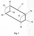
- a goal 17 typically a football goal, with up to six corner elements 18 of the invention.
- the goal furthermore includes two stanchions 10 attached in reinforcing stanchion angles.
- the goal 17 will typically also though include a net (not shown) attached along the aluminum profiles forming the crossbar, the poles and the support elements that also spans the net.
- the inner opening of the goal is typically 244 cm tall and 732 cm wide.
- the net is typically attached in the aluminum profiles by suitable hooks.
- Fig. 2 shows a detail of a corner of the goal shown on fig. 1 where an aluminum profile 7 forms a crossbar, and an aluminum profile 8 forms a post.
- the post and the crossbar are joined with a corner 18 according to the invention.
- Corner 18 includes a soft, external plastic cover 4 with substantially the same outline as the aluminum profiles 7, 8 such that it is formed a corner with a smooth transition between the corner 18 and the aluminum profiles 7, 8.
- the stanchion 10 is attached in an L- or V- shaped stanchion angle 9 with bolt holes 19.
- the stanchion angle 9 is right angled.
- the distance between the bolt holes 19 corresponds to the distance between the bolt holes in a corner tube forming a portion of the corner 18.
- Fig. 3 is an exploded view of the corner shown in fig. 2 .
- the two aluminum profiles 7, 8 include bolt holes 19 aligned with the bolt holes 19 in the stanchion angle 9 and the bolt holes in a corner tube 1.
- Four bolt holes 19 are shown and four bolts 13 with locking washers 12 extend through the stanchion angles 9, the aluminum profiles 7, 8, one insulation washer and guide 5 for each bolt, through the corner pipe 1 and into threads shaped in a threaded sleeve 20 or nut that may be welded to the corner pipe 1.
- the stanchion 10 is welded to the stanchion angle 9.
- the corner tube 1 includes two straight tubular element portions 25, 26 of substantially the same length connected by a right-angled elbow.
- the corner 18 includes two plastic shells 2, 3 that are clipped together around the right-angled elbow of the corner tube 1, such that the straight tubular element portions 25, 26 of the corner pipe 1 extend out of the plastic shells 2, 3.
- the plastic shells 2, 3 are surrounded by a soft external plastic shell 4.
- the corner pipe 1 is a bent steel pipe with a material thickness ensuring a sufficient rigidity of the corner.
- the corner pipe be made of stainless steel.
- the elbow in the corner tubular is normally a right-angle.
- the elbow in the pipe preferably has an even radius of curvature to prevent tension concentrations and buckling of the pipe.
- the radius of curvature of the pipe is preferably such that a substantially circular cross section is maintained in the elbow.
- the pipe be pressed in the elbow to simplify bending.
- Fig. 4 shows the various components of the corner 18 assembly.
- the four bolt holes 19 are located in the two straight portions of the corner pipe 1 and are of substantially the same length such that there are two bolt holes 19 in each straight portion.
- the four welded threaded sleeves 20 are located in the bolt holes 19 for attaching the bolts.
- the four guiding- and insulating washers 5 are located in each bolt hole 19, and include a sleeve shaped portion extending into each bolt hole for holding the guiding- and insulating washers 5 in their location at the corner pipe 1 before and during assembly.
- the two plastic shells 2, 3 and the soft plastic cover may terminate around the corner pipe 1 such that it is formed a tubular portion at each straight portion of the corner pipe 1 extending out of the plastic shell.
- Soft rings 14 in the same group of materials as the soft plastic shell 4 lies between the corner pipe and the plastic cover due to production technical reasons. These rings enables larger tolerances of diameter of the steel pipe, and the plastic cover can thereby more easily be adapted for steel pipes with different diameter.
- the two shell halves 2, 3 and the soft external plastic shell 4 form guiding ribs 11 fitting into rigid guiding ribs internally in the aluminum profiles.
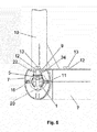
- Fig. 5 shows a cross section of an aluminum profile 7 perpendicular to a longitudinal axis of the aluminum profile, when this is used and assembled with a corner.
- the cross section is taken directly under a bolt 13.
- the corner pipe 1 with a threaded attachment sleeve 20 is tightened towards an inner guiding portion 24 of the aluminum profile 7.
- the insulating washer- and guide 5 is biased between this internal guiding portion 24 and the corner pipe 1.
- the bolt 13 also extends through the stanchion angle 9, such that the bolt holds the stanchion 10, the aluminum profiles 7, and the corner pipe 1 together.
- the locking washer 12 is made of stainless steel and the insulating washer and the guide 5 may be of an electrically insulation material.
- the bolt holes may be somewhat larger than both diameter such that it is not directly electrical contact between steel and aluminum. In this way may galvanic corrosion between the various steel and the aluminum components be prevented.
- the insulating washer isolates between the corner pipe of steel and the aluminum profiles. Direct contact between stainless steel and aluminum is not problematic, and similarly is direct contact between stainless steel and steel also unproblematic. Direct contact between steel and aluminum should be avoided.
- the locking washer 12 be substituted with, or be in addition to an electrically insulating washer.
- the sleeve portion of the guiding- and insulating washer 5 is shown with longitudinal slits and an expanded lower ring on the inside of the corner pipe 1 such that the guiding- and insulating washer 5 is held in place in the corner pipe 1 before assembly of the corner and the aluminum profile.
- the guiding ribs 11 on the plastic shell extending into ribs 16 for stiffening and guiding the aluminum profiles 7, ensure that assembly of the corner and the profile is easier, that the bolt holes are aligned with each other, that the aluminum profile is at the correct angle in relation to the goal, and stability.
- the stanchion angle 9 includes a V- shaped to the cross section extending into the corresponding recessed V- portion 22 in the aluminum profile 1.
- the mutually fitting elements contribute to holding the elements at the right position without exposing the bolts to excessive share forces. This contributes to a more stable assembly even if it not is physical contact between the bolt holes and the bolt 13.
- the stanchion angle 9 will thereby also contribute substantially to the rigidity and strength of the corner.
- the guiding- and insulating washer 5 includes an arch shaped portion with an arch shape that is adapted to the external face of the corner pipe and a plane portion with two extending elements that are adapted to the inner guiding portion 24 of the aluminum profile.
- the plane portion abuts the plane portion of the inner guiding portion 24 of the aluminum profile, and outwards extending elements extending from the plane portion and along sides of the inner guiding portion 24 of the aluminum profile to maintain a correct mutual positioning of the guiding- and insulating washer 5 in relation to the inner guiding portion 24 of the aluminum profile and the corner pipe 1.
- the outwards extending elements extending from the plane portion forms a groove for the inner guiding portion of the aluminum profile. In fig.
- FIG. 6 it is shown an aluminum profile corresponding to the aluminum profiles shown in the other figures.
- Fig. 6 highlights the guiding- and the reinforcing ribs 16, the T-groove for net hook 21, a recessed V-portion 22 for the stanchion angle (9 on fig. 5 ), forward reinforcing ribs 23 and inner guiding portion 24.
- the inner guiding portion 24 is formed by the T-groove for the net hook.
- Corner pipe 14. Soft moulded ring 2. First shell half 15. Tube elbow 3. Second shell half 16. Stiffening and guiding rib 4. Soft external plastic shell 17. Goal 5. Insulating washer and guide 18. Corner element 6. Threaded portion 19. Bolt hole 7.
- Aluminum profile 20 Threaded sleeve Aluminum profile 21 T-groove for net hook 9.
- Stanchion angle 22 Recessed V-portion 10.
- Stanchions 23 Forward stiffening ribs 11. Guiding rib 24 Inner guiding portion 12.
- Washer 25
Landscapes
- Engineering & Computer Science (AREA)
- General Engineering & Computer Science (AREA)
- Health & Medical Sciences (AREA)
- General Health & Medical Sciences (AREA)
- Physical Education & Sports Medicine (AREA)
- Mechanical Engineering (AREA)
- Connection Of Plates (AREA)
- Pivots And Pivotal Connections (AREA)
- Pinball Game Machines (AREA)
Abstract
Description
- The present invention concerns an aluminum profile joining corner element and a goal for ballgames with such aluminum profile joining elements.
- Goals for ballgames include a shape and are dimensioned in relation to the rules of the game. Such goals are in time exposed to considerable mechanical loads. Furthermore are the goals exposed to the environment and wind, such that the properties of the goal and its ability to withstand corrosion, rot, sunlight and so on important.
- There is also an issue to be able to disassemble such goals for storage out of season, for transport, to easily be able to use areas where no goals already are and so on. To allow such a mobility it is also essential that the components of the goals are manageable, and that assembly and disassembly easily can be performed with simple tools and by people without any previous skills. It is also an issue that the goal is assembled of internally compatible elements such that assembly is uncomplicated and the risk of erroneous assembly is small.
- It is particularly an object with the invention to provide a solution where electrical or galvanic contact between the various metal types is avoided to prevent galvanic corrosion. In this case is steel, stainless steel and aluminum the most relevant materials. Galvanic corrosion may lead to jamming of the assembly bolts such that they break or deform during attempts of disassembly, or that the lifespan of the various components is reduced. Galvanic corrosion is particularly problematic with aluminium threads. In cases where the threads are in aluminum will corrosion in the threads quickly lead to jamming of the bolts. In the present invention will the treads and the bolts normally be steel, and galvanic corrosion between bolts and treads is thereby less likely.
- Accordingly, the present invention concerns an aluminum profile joining corner element for joining aluminum profiles with an outline. The corner elements include a corner housing with an outline substantially corresponding to the outline of the aluminum profiles. The first and a second substantially straight tubular element extends from the corner housing, as the first tubular element forms an angle on the second tubular element. At least one bolt hole extend through the first and the second tubular element respectively. A guiding- and insulating washer is attached to each bolt hole.
- Outline is in this connection meant to describe the external shape of the aluminum profiles around a cross section of the aluminum profiles in a plane perpendicular to the longitudinal axis of the aluminum profiles.
- The first and the second substantially straight tubular element extending from the corner housing will normally be connected with each other at an elbow, as the first and the second substantially straight tubular element and the elbow is shaped out of one single metal tubular piece and forms a corner tube. The corner housing surrounds the elbow of the corner tube. The metal tube piece is preferably made of galvanized or hot-dip galvanized steel, but may also be made of stainless steel.
- The corner housing may include an internal shell made of a first plastic material with an external layer of a second plastic material. The external plastic material may be softer than the internal plastic material. The internal shell may be made of a hard plastic and the external shell may be made of a soft plastic.
- The external layer of soft plastic material can be applied by overcasting the internal shell. The overcasting of the soft plastic material has several tasks. The soft, external shell both seals, accommodates for inaccuracies, locks the internal shell together, provides a whole outer side and prevents rubbing sounds and squeaking. The overcasting may in other words be applied after the inner shell is assembled onto the tubular element/tubular elements, and forms the surface facing the aluminum profiles.
- The corner housing may include a first shell half and a second shell half connected to the first shell half.
- The first shell half and the second shell half can form the shell of hard plastic and the external layer of soft plastic can surround the first shell half and the second shell half.
- The guiding- and insulation washer can be shaped of a plastic material and may include an arch shaped portion with an arch adapted to a diameter of the first and the second substantially straight tubular element, and a substantially planer portion adapted to an inner surface of the aluminum profiles to be joined.
- Furthermore the invention includes a goal for ballgames including at least aluminum profile joining corner elements for joining at least a first, a second and a third aluminum profile forming a first post, a second post and a crossbar. The aluminum profiles include an outline, and the goal furthermore includes a corner housing with an outline substantially corresponding to the outline of the aluminum profiles. A first and a second substantially straight tubular element extends from the corner housing, as the first tubular element forms an angle to the second tubular element. The first and the second substantially straight tubular element extending from the corner housing are connected to each other with a tubular elbow. The fist and the second substantially straight tubular element and the elbow are formed as one single tubular piece and form a corner tube. The corner housing surrounds the elbow of the corner tube. At least one bolt hole extends through the first and the second tubular element respectively. A guiding- and insulation washer is attached to each bolt hole. Each post is attached to one of the substantially straight tubular elements, in at least one end, as the tubular element extends internally in the post, and as at least one bolt extends through a wall of the aluminum profile of the post, and the substantially straight tubular element. The crossbar is attached in one of the substantially straight tubular elements at each end, as each tubular element extends internally in the crossbar, and as at least one bolt extends through a wall of the aluminum profile of the crossbar and each substantially straight tubular element.
- The goal may include two, four or six aluminum profile joining corner elements.
- The goal may furthermore include an L- or V- shaped stanchion angle with bolt holes for attaching a stanchion, as the stanchion angle includes at least two bolt holes, and as at least two bolts extend through a locking washer, a stanchion angle, an aluminum profile, a guiding- and insulating washer and a substantially straight tubular element respectively, as a threaded element is attached in the substantially straight tubular element for each bolt, and as the bolt is screwed into the threaded element.
- The locking washers and the guiding- and insulating washers may be of an electrically insulating material, and the bolt holes in the stanchion angle and the aluminum profiles may include a larger diameter than the bolt such that a substantially straight is element is electrically isolated in relation to the aluminum profiles and the stanchion angle.
- Short description of the enclosed figures:
-
Fig. 1 is a perspective view of a football goal with corners according to the invention; -
Fig. 2 is a detail offig 1 where a corner according to the invention is shown; -
Fig. 3 is an exploded view of a corner for a goal according to the invention where the aluminum profiles of the goal are shown; -
Fig. 4 is an exploded view of a corner for a goal according to the invention where the components of the goal are shown; -
Fig. 5 is crossection of an aluminum profile with a corner according to the invention; and -
Fig. 6 is an end section of an aluminum profile that is adapted for joining with a corner according to the invention. - In
fig. 1 it is shown agoal 17, typically a football goal, with up to sixcorner elements 18 of the invention. The goal furthermore includes twostanchions 10 attached in reinforcing stanchion angles. Thegoal 17 will typically also though include a net (not shown) attached along the aluminum profiles forming the crossbar, the poles and the support elements that also spans the net. The inner opening of the goal is typically 244 cm tall and 732 cm wide. The net is typically attached in the aluminum profiles by suitable hooks. -
Fig. 2 shows a detail of a corner of the goal shown onfig. 1 where analuminum profile 7 forms a crossbar, and analuminum profile 8 forms a post. The post and the crossbar are joined with acorner 18 according to the invention.Corner 18 includes a soft, externalplastic cover 4 with substantially the same outline as thealuminum profiles corner 18 and thealuminum profiles stanchion 10 is attached in an L- or V-shaped stanchion angle 9 withbolt holes 19. Thestanchion angle 9 is right angled. The distance between thebolt holes 19 corresponds to the distance between the bolt holes in a corner tube forming a portion of thecorner 18. -
Fig. 3 is an exploded view of the corner shown infig. 2 . The twoaluminum profiles bolt holes 19 aligned with thebolt holes 19 in thestanchion angle 9 and the bolt holes in a corner tube 1. Four bolt holes 19 are shown and fourbolts 13 with lockingwashers 12 extend through the stanchion angles 9, thealuminum profiles guide 5 for each bolt, through the corner pipe 1 and into threads shaped in a threadedsleeve 20 or nut that may be welded to the corner pipe 1. Thestanchion 10 is welded to thestanchion angle 9. The corner tube 1 includes two straighttubular element portions corner 18 includes two plastic shells 2, 3 that are clipped together around the right-angled elbow of the corner tube 1, such that the straighttubular element portions plastic shell 4. The corner pipe 1 is a bent steel pipe with a material thickness ensuring a sufficient rigidity of the corner. Alternatively may the corner pipe be made of stainless steel. The elbow in the corner tubular is normally a right-angle. The elbow in the pipe preferably has an even radius of curvature to prevent tension concentrations and buckling of the pipe. The radius of curvature of the pipe is preferably such that a substantially circular cross section is maintained in the elbow. Alternatively may the pipe be pressed in the elbow to simplify bending. -
Fig. 4 shows the various components of thecorner 18 assembly. The fourbolt holes 19 are located in the two straight portions of the corner pipe 1 and are of substantially the same length such that there are twobolt holes 19 in each straight portion. The four welded threadedsleeves 20 are located in the bolt holes 19 for attaching the bolts. The four guiding- andinsulating washers 5 are located in eachbolt hole 19, and include a sleeve shaped portion extending into each bolt hole for holding the guiding- andinsulating washers 5 in their location at the corner pipe 1 before and during assembly. The two plastic shells 2, 3 and the soft plastic cover may terminate around the corner pipe 1 such that it is formed a tubular portion at each straight portion of the corner pipe 1 extending out of the plastic shell. Soft rings 14 in the same group of materials as the softplastic shell 4 lies between the corner pipe and the plastic cover due to production technical reasons. These rings enables larger tolerances of diameter of the steel pipe, and the plastic cover can thereby more easily be adapted for steel pipes with different diameter. After assembly, the two shell halves 2, 3 and the soft externalplastic shell 4form guiding ribs 11 fitting into rigid guiding ribs internally in the aluminum profiles. -
Fig. 5 shows a cross section of analuminum profile 7 perpendicular to a longitudinal axis of the aluminum profile, when this is used and assembled with a corner. The cross section is taken directly under abolt 13. The corner pipe 1 with a threadedattachment sleeve 20 is tightened towards aninner guiding portion 24 of thealuminum profile 7. The insulating washer- andguide 5 is biased between this internal guidingportion 24 and the corner pipe 1. Thebolt 13 also extends through thestanchion angle 9, such that the bolt holds thestanchion 10, thealuminum profiles 7, and the corner pipe 1 together. The lockingwasher 12 is made of stainless steel and the insulating washer and theguide 5 may be of an electrically insulation material. The bolt holes may be somewhat larger than both diameter such that it is not directly electrical contact between steel and aluminum. In this way may galvanic corrosion between the various steel and the aluminum components be prevented. The insulating washer isolates between the corner pipe of steel and the aluminum profiles. Direct contact between stainless steel and aluminum is not problematic, and similarly is direct contact between stainless steel and steel also unproblematic. Direct contact between steel and aluminum should be avoided. Alternatively may the lockingwasher 12 be substituted with, or be in addition to an electrically insulating washer. - The sleeve portion of the guiding- and
insulating washer 5 is shown with longitudinal slits and an expanded lower ring on the inside of the corner pipe 1 such that the guiding- andinsulating washer 5 is held in place in the corner pipe 1 before assembly of the corner and the aluminum profile. - The guiding
ribs 11 on the plastic shell extending intoribs 16 for stiffening and guiding thealuminum profiles 7, ensure that assembly of the corner and the profile is easier, that the bolt holes are aligned with each other, that the aluminum profile is at the correct angle in relation to the goal, and stability. - The
stanchion angle 9 includes a V- shaped to the cross section extending into the corresponding recessed V-portion 22 in the aluminum profile 1. The mutually fitting elements contribute to holding the elements at the right position without exposing the bolts to excessive share forces. This contributes to a more stable assembly even if it not is physical contact between the bolt holes and thebolt 13. Thestanchion angle 9 will thereby also contribute substantially to the rigidity and strength of the corner. - The guiding- and
insulating washer 5 includes an arch shaped portion with an arch shape that is adapted to the external face of the corner pipe and a plane portion with two extending elements that are adapted to the inner guidingportion 24 of the aluminum profile. The plane portion abuts the plane portion of the inner guidingportion 24 of the aluminum profile, and outwards extending elements extending from the plane portion and along sides of the inner guidingportion 24 of the aluminum profile to maintain a correct mutual positioning of the guiding- andinsulating washer 5 in relation to the inner guidingportion 24 of the aluminum profile and the corner pipe 1. The outwards extending elements extending from the plane portion forms a groove for the inner guiding portion of the aluminum profile. Infig. 6 it is shown an aluminum profile corresponding to the aluminum profiles shown in the other figures.Fig. 6 highlights the guiding- and the reinforcingribs 16, the T-groove fornet hook 21, a recessed V-portion 22 for the stanchion angle (9 onfig. 5 ), forward reinforcingribs 23 and inner guidingportion 24. Theinner guiding portion 24 is formed by the T-groove for the net hook.1. Corner pipe 14. Soft moulded ring 2. First shell half 15. Tube elbow 3. Second shell half 16. Stiffening and guiding rib 4. Soft external plastic shell 17. Goal 5. Insulating washer and guide 18. Corner element 6. Threaded portion 19. Bolt hole 7. Aluminum profile 20 Threaded sleeve 8. Aluminum profile 21 T-groove for net hook 9. Stanchion angle 22 Recessed V- portion 10. Stanchions 23 Forward stiffening ribs 11. Guiding rib 24 Inner guiding portion 12. Washer 25 First substantially straight corner element 13. Bolt 26 Second substantially straight corner element
Claims (11)
- An aluminum profile joining corner element (18) for joining aluminum profiles (7, 8) with an outline, comprising:a corner housing with an outline substantially corresponding to the outline of the aluminum profiles (7, 8);a first and a second substantially straight tubular element extending from the corner housing, wherein the first tubular element forms an angle to the second tubular element;at least one bolt hole (19) extending through the first and the second tubular element respectively; anda guiding- and insulating washer (5) attached in each bolt hole (19);wherein the first and the second substantially straight tubular element extending from the corner housing is connected to each other in an elbow,wherein the first and the second substantially straight tubular element and the elbow is shaped of one single metal tubular pipe and form a corner pipe 1; andwherein the corner housing surrounds the elbow of the corner tube.
- The aluminum profile joining corner element (18), according to claim 1
wherein the corner housing includes an outer shell of a first plastic material and an external layer of a second plastic material. - The aluminum profile joining corner element (18) wherein the first plastic material is harder than the second plastic material.
- The aluminum profile joining corner element (18) according to one of the preceding claims wherein the corner housing includes a first shell half (2) and a second shell half (3) connected to the first shell half (2).
- The aluminum profile joining corner element (18), according to claim 3 and 4 wherein the first shell half (2) and the second shell half (3) form the shell of the first plastic material and wherein the external layer of a second plastic material surrounds the first shell half (2) and the second shell half (3).
- The aluminum profile joining corner element (18) according to one of the preceding claims, wherein the guiding- and insulating washer (85) is shaped of a plastic material and includes an arch shaped portion with an arch adapted to a diameter of the first and the second substantially straight tubular element, and a substantially plane portion adapted to an inner face of the aluminum profiles (7, 8) to be joined.
- A goal (17) for a ballgame including at least two aluminum profile joining corner elements (18) for joining at least a first, a second and a third aluminum profile (7, 8) forming a first post, a second post and a crossbar, wherein the aluminum profiles (6, 7) include an outline, the goal (17) further comprising:a corner housing with an outline substantially corresponding to the outline of the aluminum profile (7, 8);a first and a second substantially straight tubular element (25, 26) extending from the corner housing, wherein the first substantially straight corner housing (25) forms an angle to the second substantially straight tubular element (26) wherein the first and the second substantially straight tubular element extend from the corner housing are connected with each other at an elbow, wherein the first and the second substantially straight tubular element and the elbow are shaped of one single tubular piece and forms a corner tube (1);that the corner housing includes the elbow of the corner tube;at least one bolt hole (9) extending through the first and the second tubular element (25, 26) respectively;a guiding- and insulating washer attached in each bolt hole (19);that each post is secured in one of the substantially straight tubular elements, in at least one end, wherein the substantially straight tubular element extends internally in the post, and wherein at least one bolt (13) extends through a wall in the aluminum profile of the post and in the substantially straight tubular element; andthat the crossbar at each end is secured in one of the substantially straight tubular elements, wherein each substantially straight tubular element extends internally in the crossbar, and wherein at least one bolt (13) extends through a wall in the aluminum profile of the crossbar and each substantially straight tubular element (25, 26).
- The goal according to claim 7, further including four aluminum profile joining corner elements (18).
- The goal according to claim 7 or 8, further including at least two corners, each including an L- or V- shaped stanchion angle (9) with bolt holes (19), for attaching a stanchion (10) wherein the stanchion angle (9) includes at least two bolt holes (19), and wherein at least two bolts (13) extend through a locking washer (12), a stanchion angle (9), an aluminum profile (7, 8), a guiding- and insulating washer (5) and a substantially straight tubular element respectively;
wherein a threaded element (20) is attached in one of the substantially straight tubular elements (25, 26) for each bolt; and
wherein each bolt (13) is screwed into each threaded element (20). - The goal according to claim 9, wherein the guiding- and insulating washers (5) are of an electrically insulating material, wherein the bolt holes (19) of the substantially straight tubular elements (25, 26) are electrically isolated in relation to the aluminum profiles (7, 8).
- The goal according to claim 7, including six aluminum profile joining corner elements (18).
Applications Claiming Priority (1)
| Application Number | Priority Date | Filing Date | Title |
|---|---|---|---|
| NO20141465A NO344312B1 (en) | 2014-12-04 | 2014-12-04 | An aluminum profile-splicing corner element and a ball game target with such elements |
Publications (2)
| Publication Number | Publication Date |
|---|---|
| EP3053631A1 true EP3053631A1 (en) | 2016-08-10 |
| EP3053631B1 EP3053631B1 (en) | 2018-10-17 |
Family
ID=55862498
Family Applications (1)
| Application Number | Title | Priority Date | Filing Date |
|---|---|---|---|
| EP15197432.6A Active EP3053631B1 (en) | 2014-12-04 | 2015-12-02 | An aluminium section joining corner element and a goal for ball games with such elements |
Country Status (2)
| Country | Link |
|---|---|
| EP (1) | EP3053631B1 (en) |
| NO (1) | NO344312B1 (en) |
Cited By (1)
| Publication number | Priority date | Publication date | Assignee | Title |
|---|---|---|---|---|
| EP3653273A1 (en) * | 2018-10-31 | 2020-05-20 | Net World Sports Limited | Modular crossbar |
Citations (5)
| Publication number | Priority date | Publication date | Assignee | Title |
|---|---|---|---|---|
| US3532369A (en) * | 1968-09-24 | 1970-10-06 | Beautiline Ltd | Corner construction and method of connecting rectangular frame members together |
| US5681231A (en) * | 1994-08-10 | 1997-10-28 | Reeves; Francis J. | Collapsible game goal |
| US20070145688A1 (en) * | 2005-12-28 | 2007-06-28 | Kwik Goal Ltd. | Connector for sports goal frame |
| JP2011217958A (en) * | 2010-04-09 | 2011-11-04 | Nikkeikin Aluminium Core Technology Co Ltd | Goal for ball game |
| US20130190109A1 (en) * | 2010-02-12 | 2013-07-25 | Michael Rigoli | Net Frame Assembly and Anti-Rebound System |
-
2014
- 2014-12-04 NO NO20141465A patent/NO344312B1/en unknown
-
2015
- 2015-12-02 EP EP15197432.6A patent/EP3053631B1/en active Active
Patent Citations (5)
| Publication number | Priority date | Publication date | Assignee | Title |
|---|---|---|---|---|
| US3532369A (en) * | 1968-09-24 | 1970-10-06 | Beautiline Ltd | Corner construction and method of connecting rectangular frame members together |
| US5681231A (en) * | 1994-08-10 | 1997-10-28 | Reeves; Francis J. | Collapsible game goal |
| US20070145688A1 (en) * | 2005-12-28 | 2007-06-28 | Kwik Goal Ltd. | Connector for sports goal frame |
| US20130190109A1 (en) * | 2010-02-12 | 2013-07-25 | Michael Rigoli | Net Frame Assembly and Anti-Rebound System |
| JP2011217958A (en) * | 2010-04-09 | 2011-11-04 | Nikkeikin Aluminium Core Technology Co Ltd | Goal for ball game |
Cited By (1)
| Publication number | Priority date | Publication date | Assignee | Title |
|---|---|---|---|---|
| EP3653273A1 (en) * | 2018-10-31 | 2020-05-20 | Net World Sports Limited | Modular crossbar |
Also Published As
| Publication number | Publication date |
|---|---|
| NO20141465A1 (en) | 2016-06-06 |
| NO344312B1 (en) | 2019-11-04 |
| EP3053631B1 (en) | 2018-10-17 |
Similar Documents
| Publication | Publication Date | Title |
|---|---|---|
| JP6755083B2 (en) | spiral staircase | |
| KR100966624B1 (en) | Fence connector | |
| AU2017204420A1 (en) | Pool noodle connectors | |
| US20170130478A1 (en) | Storage Basket | |
| EP3053631B1 (en) | An aluminium section joining corner element and a goal for ball games with such elements | |
| US9115839B1 (en) | Cylindrical foam tube strengthening and interconnecting system | |
| KR200481367Y1 (en) | Cabletray | |
| US20170074435A1 (en) | Device for connecting a pump body to a pipe of a hydraulic system | |
| JP2010013862A (en) | Beam connecting structure | |
| KR101714420B1 (en) | Structure-type join system | |
| JP2008019624A (en) | Beam installing structure of fence | |
| KR101383355B1 (en) | Clamp for supporter of form-shore | |
| JP2013028974A (en) | Handrail | |
| US11471720B2 (en) | Playground | |
| KR101507385B1 (en) | Space frame with connection structure using adapter for weight reduction | |
| JP4889115B2 (en) | Wire body erection device | |
| KR100257848B1 (en) | Scaffold system with composite materials | |
| KR20120056445A (en) | Deck for amusement park rides | |
| KR20070031116A (en) | Prefabricated Panel Tank Base Frame | |
| KR20150002958U (en) | Fixing Type Rotating Bracket Apparatus for Supporting Beam of Shoring | |
| KR100453805B1 (en) | The space frame for constructing cubic structure | |
| KR200438242Y1 (en) | Construction composite member | |
| JP2004011180A (en) | Joining structure of waterproof truss | |
| JP3168873U (en) | Protective equipment | |
| TWM517258U (en) | Improved assembling structure of float ball holder |
Legal Events
| Date | Code | Title | Description |
|---|---|---|---|
| PUAI | Public reference made under article 153(3) epc to a published international application that has entered the european phase |
Free format text: ORIGINAL CODE: 0009012 |
|
| 17P | Request for examination filed |
Effective date: 20151202 |
|
| AK | Designated contracting states |
Kind code of ref document: A1 Designated state(s): AL AT BE BG CH CY CZ DE DK EE ES FI FR GB GR HR HU IE IS IT LI LT LU LV MC MK MT NL NO PL PT RO RS SE SI SK SM TR |
|
| AX | Request for extension of the european patent |
Extension state: BA ME |
|
| 17Q | First examination report despatched |
Effective date: 20171030 |
|
| RIC1 | Information provided on ipc code assigned before grant |
Ipc: E04B 1/58 20060101ALI20180503BHEP Ipc: F16B 12/40 20060101ALI20180503BHEP Ipc: A63B 63/00 20060101AFI20180503BHEP Ipc: E04B 1/24 20060101ALI20180503BHEP |
|
| GRAP | Despatch of communication of intention to grant a patent |
Free format text: ORIGINAL CODE: EPIDOSNIGR1 |
|
| INTG | Intention to grant announced |
Effective date: 20180615 |
|
| GRAS | Grant fee paid |
Free format text: ORIGINAL CODE: EPIDOSNIGR3 |
|
| GRAA | (expected) grant |
Free format text: ORIGINAL CODE: 0009210 |
|
| AK | Designated contracting states |
Kind code of ref document: B1 Designated state(s): AL AT BE BG CH CY CZ DE DK EE ES FI FR GB GR HR HU IE IS IT LI LT LU LV MC MK MT NL NO PL PT RO RS SE SI SK SM TR |
|
| AX | Request for extension of the european patent |
Extension state: BA ME |
|
| REG | Reference to a national code |
Ref country code: GB Ref legal event code: FG4D |
|
| REG | Reference to a national code |
Ref country code: CH Ref legal event code: EP |
|
| REG | Reference to a national code |
Ref country code: IE Ref legal event code: FG4D |
|
| REG | Reference to a national code |
Ref country code: DE Ref legal event code: R096 Ref document number: 602015018217 Country of ref document: DE Ref country code: AT Ref legal event code: REF Ref document number: 1053312 Country of ref document: AT Kind code of ref document: T Effective date: 20181115 |
|
| REG | Reference to a national code |
Ref country code: NL Ref legal event code: MP Effective date: 20181017 |
|
| REG | Reference to a national code |
Ref country code: LT Ref legal event code: MG4D |
|
| REG | Reference to a national code |
Ref country code: AT Ref legal event code: MK05 Ref document number: 1053312 Country of ref document: AT Kind code of ref document: T Effective date: 20181017 |
|
| PG25 | Lapsed in a contracting state [announced via postgrant information from national office to epo] |
Ref country code: NL Free format text: LAPSE BECAUSE OF FAILURE TO SUBMIT A TRANSLATION OF THE DESCRIPTION OR TO PAY THE FEE WITHIN THE PRESCRIBED TIME-LIMIT Effective date: 20181017 |
|
| PG25 | Lapsed in a contracting state [announced via postgrant information from national office to epo] |
Ref country code: BG Free format text: LAPSE BECAUSE OF FAILURE TO SUBMIT A TRANSLATION OF THE DESCRIPTION OR TO PAY THE FEE WITHIN THE PRESCRIBED TIME-LIMIT Effective date: 20190117 Ref country code: NO Free format text: LAPSE BECAUSE OF FAILURE TO SUBMIT A TRANSLATION OF THE DESCRIPTION OR TO PAY THE FEE WITHIN THE PRESCRIBED TIME-LIMIT Effective date: 20190117 Ref country code: PL Free format text: LAPSE BECAUSE OF FAILURE TO SUBMIT A TRANSLATION OF THE DESCRIPTION OR TO PAY THE FEE WITHIN THE PRESCRIBED TIME-LIMIT Effective date: 20181017 Ref country code: FI Free format text: LAPSE BECAUSE OF FAILURE TO SUBMIT A TRANSLATION OF THE DESCRIPTION OR TO PAY THE FEE WITHIN THE PRESCRIBED TIME-LIMIT Effective date: 20181017 Ref country code: LT Free format text: LAPSE BECAUSE OF FAILURE TO SUBMIT A TRANSLATION OF THE DESCRIPTION OR TO PAY THE FEE WITHIN THE PRESCRIBED TIME-LIMIT Effective date: 20181017 Ref country code: LV Free format text: LAPSE BECAUSE OF FAILURE TO SUBMIT A TRANSLATION OF THE DESCRIPTION OR TO PAY THE FEE WITHIN THE PRESCRIBED TIME-LIMIT Effective date: 20181017 Ref country code: HR Free format text: LAPSE BECAUSE OF FAILURE TO SUBMIT A TRANSLATION OF THE DESCRIPTION OR TO PAY THE FEE WITHIN THE PRESCRIBED TIME-LIMIT Effective date: 20181017 Ref country code: ES Free format text: LAPSE BECAUSE OF FAILURE TO SUBMIT A TRANSLATION OF THE DESCRIPTION OR TO PAY THE FEE WITHIN THE PRESCRIBED TIME-LIMIT Effective date: 20181017 Ref country code: AT Free format text: LAPSE BECAUSE OF FAILURE TO SUBMIT A TRANSLATION OF THE DESCRIPTION OR TO PAY THE FEE WITHIN THE PRESCRIBED TIME-LIMIT Effective date: 20181017 Ref country code: IS Free format text: LAPSE BECAUSE OF FAILURE TO SUBMIT A TRANSLATION OF THE DESCRIPTION OR TO PAY THE FEE WITHIN THE PRESCRIBED TIME-LIMIT Effective date: 20190217 |
|
| PG25 | Lapsed in a contracting state [announced via postgrant information from national office to epo] |
Ref country code: PT Free format text: LAPSE BECAUSE OF FAILURE TO SUBMIT A TRANSLATION OF THE DESCRIPTION OR TO PAY THE FEE WITHIN THE PRESCRIBED TIME-LIMIT Effective date: 20190217 Ref country code: GR Free format text: LAPSE BECAUSE OF FAILURE TO SUBMIT A TRANSLATION OF THE DESCRIPTION OR TO PAY THE FEE WITHIN THE PRESCRIBED TIME-LIMIT Effective date: 20190118 Ref country code: SE Free format text: LAPSE BECAUSE OF FAILURE TO SUBMIT A TRANSLATION OF THE DESCRIPTION OR TO PAY THE FEE WITHIN THE PRESCRIBED TIME-LIMIT Effective date: 20181017 Ref country code: RS Free format text: LAPSE BECAUSE OF FAILURE TO SUBMIT A TRANSLATION OF THE DESCRIPTION OR TO PAY THE FEE WITHIN THE PRESCRIBED TIME-LIMIT Effective date: 20181017 Ref country code: AL Free format text: LAPSE BECAUSE OF FAILURE TO SUBMIT A TRANSLATION OF THE DESCRIPTION OR TO PAY THE FEE WITHIN THE PRESCRIBED TIME-LIMIT Effective date: 20181017 |
|
| REG | Reference to a national code |
Ref country code: DE Ref legal event code: R119 Ref document number: 602015018217 Country of ref document: DE |
|
| PG25 | Lapsed in a contracting state [announced via postgrant information from national office to epo] |
Ref country code: DK Free format text: LAPSE BECAUSE OF FAILURE TO SUBMIT A TRANSLATION OF THE DESCRIPTION OR TO PAY THE FEE WITHIN THE PRESCRIBED TIME-LIMIT Effective date: 20181017 Ref country code: CZ Free format text: LAPSE BECAUSE OF FAILURE TO SUBMIT A TRANSLATION OF THE DESCRIPTION OR TO PAY THE FEE WITHIN THE PRESCRIBED TIME-LIMIT Effective date: 20181017 Ref country code: IT Free format text: LAPSE BECAUSE OF FAILURE TO SUBMIT A TRANSLATION OF THE DESCRIPTION OR TO PAY THE FEE WITHIN THE PRESCRIBED TIME-LIMIT Effective date: 20181017 |
|
| REG | Reference to a national code |
Ref country code: CH Ref legal event code: PL |
|
| PLBE | No opposition filed within time limit |
Free format text: ORIGINAL CODE: 0009261 |
|
| STAA | Information on the status of an ep patent application or granted ep patent |
Free format text: STATUS: NO OPPOSITION FILED WITHIN TIME LIMIT |
|
| PG25 | Lapsed in a contracting state [announced via postgrant information from national office to epo] |
Ref country code: LU Free format text: LAPSE BECAUSE OF NON-PAYMENT OF DUE FEES Effective date: 20181202 Ref country code: SK Free format text: LAPSE BECAUSE OF FAILURE TO SUBMIT A TRANSLATION OF THE DESCRIPTION OR TO PAY THE FEE WITHIN THE PRESCRIBED TIME-LIMIT Effective date: 20181017 Ref country code: MC Free format text: LAPSE BECAUSE OF FAILURE TO SUBMIT A TRANSLATION OF THE DESCRIPTION OR TO PAY THE FEE WITHIN THE PRESCRIBED TIME-LIMIT Effective date: 20181017 Ref country code: SM Free format text: LAPSE BECAUSE OF FAILURE TO SUBMIT A TRANSLATION OF THE DESCRIPTION OR TO PAY THE FEE WITHIN THE PRESCRIBED TIME-LIMIT Effective date: 20181017 Ref country code: EE Free format text: LAPSE BECAUSE OF FAILURE TO SUBMIT A TRANSLATION OF THE DESCRIPTION OR TO PAY THE FEE WITHIN THE PRESCRIBED TIME-LIMIT Effective date: 20181017 Ref country code: RO Free format text: LAPSE BECAUSE OF FAILURE TO SUBMIT A TRANSLATION OF THE DESCRIPTION OR TO PAY THE FEE WITHIN THE PRESCRIBED TIME-LIMIT Effective date: 20181017 |
|
| REG | Reference to a national code |
Ref country code: IE Ref legal event code: MM4A |
|
| 26N | No opposition filed |
Effective date: 20190718 |
|
| REG | Reference to a national code |
Ref country code: BE Ref legal event code: MM Effective date: 20181231 |
|
| PG25 | Lapsed in a contracting state [announced via postgrant information from national office to epo] |
Ref country code: IE Free format text: LAPSE BECAUSE OF NON-PAYMENT OF DUE FEES Effective date: 20181202 Ref country code: SI Free format text: LAPSE BECAUSE OF FAILURE TO SUBMIT A TRANSLATION OF THE DESCRIPTION OR TO PAY THE FEE WITHIN THE PRESCRIBED TIME-LIMIT Effective date: 20181017 Ref country code: DE Free format text: LAPSE BECAUSE OF NON-PAYMENT OF DUE FEES Effective date: 20190702 Ref country code: FR Free format text: LAPSE BECAUSE OF NON-PAYMENT OF DUE FEES Effective date: 20181217 |
|
| PG25 | Lapsed in a contracting state [announced via postgrant information from national office to epo] |
Ref country code: BE Free format text: LAPSE BECAUSE OF NON-PAYMENT OF DUE FEES Effective date: 20181231 |
|
| PG25 | Lapsed in a contracting state [announced via postgrant information from national office to epo] |
Ref country code: LI Free format text: LAPSE BECAUSE OF NON-PAYMENT OF DUE FEES Effective date: 20181231 Ref country code: CH Free format text: LAPSE BECAUSE OF NON-PAYMENT OF DUE FEES Effective date: 20181231 |
|
| PG25 | Lapsed in a contracting state [announced via postgrant information from national office to epo] |
Ref country code: MT Free format text: LAPSE BECAUSE OF NON-PAYMENT OF DUE FEES Effective date: 20181202 |
|
| PG25 | Lapsed in a contracting state [announced via postgrant information from national office to epo] |
Ref country code: TR Free format text: LAPSE BECAUSE OF FAILURE TO SUBMIT A TRANSLATION OF THE DESCRIPTION OR TO PAY THE FEE WITHIN THE PRESCRIBED TIME-LIMIT Effective date: 20181017 |
|
| PG25 | Lapsed in a contracting state [announced via postgrant information from national office to epo] |
Ref country code: MK Free format text: LAPSE BECAUSE OF NON-PAYMENT OF DUE FEES Effective date: 20181017 Ref country code: CY Free format text: LAPSE BECAUSE OF FAILURE TO SUBMIT A TRANSLATION OF THE DESCRIPTION OR TO PAY THE FEE WITHIN THE PRESCRIBED TIME-LIMIT Effective date: 20181017 Ref country code: HU Free format text: LAPSE BECAUSE OF FAILURE TO SUBMIT A TRANSLATION OF THE DESCRIPTION OR TO PAY THE FEE WITHIN THE PRESCRIBED TIME-LIMIT; INVALID AB INITIO Effective date: 20151202 |
|
| GBPC | Gb: european patent ceased through non-payment of renewal fee |
Effective date: 20191202 |
|
| PG25 | Lapsed in a contracting state [announced via postgrant information from national office to epo] |
Ref country code: GB Free format text: LAPSE BECAUSE OF NON-PAYMENT OF DUE FEES Effective date: 20191202 |