EP3653248B1 - Respirators - Google Patents
Respirators Download PDFInfo
- Publication number
- EP3653248B1 EP3653248B1 EP20150286.1A EP20150286A EP3653248B1 EP 3653248 B1 EP3653248 B1 EP 3653248B1 EP 20150286 A EP20150286 A EP 20150286A EP 3653248 B1 EP3653248 B1 EP 3653248B1
- Authority
- EP
- European Patent Office
- Prior art keywords
- ventilation
- pressure
- oxygen saturation
- programmable controller
- volume
- Prior art date
- Legal status (The legal status is an assumption and is not a legal conclusion. Google has not performed a legal analysis and makes no representation as to the accuracy of the status listed.)
- Active
Links
- QVGXLLKOCUKJST-UHFFFAOYSA-N atomic oxygen Chemical compound [O] QVGXLLKOCUKJST-UHFFFAOYSA-N 0.000 claims description 77
- 239000001301 oxygen Substances 0.000 claims description 77
- 229910052760 oxygen Inorganic materials 0.000 claims description 77
- 230000029058 respiratory gaseous exchange Effects 0.000 claims description 55
- 230000000241 respiratory effect Effects 0.000 claims description 21
- 239000007789 gas Substances 0.000 claims description 17
- 210000004072 lung Anatomy 0.000 claims description 12
- 230000003434 inspiratory effect Effects 0.000 claims description 10
- 239000000203 mixture Substances 0.000 claims description 2
- 238000009423 ventilation Methods 0.000 description 109
- 239000003570 air Substances 0.000 description 27
- 230000002269 spontaneous effect Effects 0.000 description 18
- 206010036590 Premature baby Diseases 0.000 description 12
- 208000008784 apnea Diseases 0.000 description 12
- 239000002775 capsule Substances 0.000 description 11
- 238000000034 method Methods 0.000 description 6
- 230000001360 synchronised effect Effects 0.000 description 6
- 239000008280 blood Substances 0.000 description 5
- 210000004369 blood Anatomy 0.000 description 5
- 230000001960 triggered effect Effects 0.000 description 5
- IJGRMHOSHXDMSA-UHFFFAOYSA-N Atomic nitrogen Chemical compound N#N IJGRMHOSHXDMSA-UHFFFAOYSA-N 0.000 description 4
- 230000033228 biological regulation Effects 0.000 description 4
- 230000008859 change Effects 0.000 description 4
- 210000001015 abdomen Anatomy 0.000 description 3
- 230000003044 adaptive effect Effects 0.000 description 3
- 230000007423 decrease Effects 0.000 description 3
- 230000002028 premature Effects 0.000 description 3
- 238000002560 therapeutic procedure Methods 0.000 description 3
- CURLTUGMZLYLDI-UHFFFAOYSA-N Carbon dioxide Chemical compound O=C=O CURLTUGMZLYLDI-UHFFFAOYSA-N 0.000 description 2
- 230000037396 body weight Effects 0.000 description 2
- 125000004122 cyclic group Chemical group 0.000 description 2
- 230000003247 decreasing effect Effects 0.000 description 2
- 230000001419 dependent effect Effects 0.000 description 2
- 230000015654 memory Effects 0.000 description 2
- 238000012544 monitoring process Methods 0.000 description 2
- 229910052757 nitrogen Inorganic materials 0.000 description 2
- 210000003437 trachea Anatomy 0.000 description 2
- 206010021133 Hypoventilation Diseases 0.000 description 1
- 206010021143 Hypoxia Diseases 0.000 description 1
- 230000001133 acceleration Effects 0.000 description 1
- 239000012080 ambient air Substances 0.000 description 1
- 230000003321 amplification Effects 0.000 description 1
- 230000001174 ascending effect Effects 0.000 description 1
- 229910002092 carbon dioxide Inorganic materials 0.000 description 1
- 239000001569 carbon dioxide Substances 0.000 description 1
- 230000006835 compression Effects 0.000 description 1
- 238000007906 compression Methods 0.000 description 1
- 238000010276 construction Methods 0.000 description 1
- 238000013461 design Methods 0.000 description 1
- 238000001514 detection method Methods 0.000 description 1
- 238000010586 diagram Methods 0.000 description 1
- 208000037265 diseases, disorders, signs and symptoms Diseases 0.000 description 1
- 239000003814 drug Substances 0.000 description 1
- 229940079593 drug Drugs 0.000 description 1
- 229940124645 emergency medicine Drugs 0.000 description 1
- 230000004907 flux Effects 0.000 description 1
- 230000006870 function Effects 0.000 description 1
- 208000000122 hyperventilation Diseases 0.000 description 1
- 230000000870 hyperventilation Effects 0.000 description 1
- 231100000516 lung damage Toxicity 0.000 description 1
- 239000000463 material Substances 0.000 description 1
- 238000005259 measurement Methods 0.000 description 1
- 238000005399 mechanical ventilation Methods 0.000 description 1
- 238000003199 nucleic acid amplification method Methods 0.000 description 1
- 230000008569 process Effects 0.000 description 1
- 230000002685 pulmonary effect Effects 0.000 description 1
- 230000011514 reflex Effects 0.000 description 1
- 230000004044 response Effects 0.000 description 1
- 238000005070 sampling Methods 0.000 description 1
- 210000002784 stomach Anatomy 0.000 description 1
- 238000012360 testing method Methods 0.000 description 1
- 230000003519 ventilatory effect Effects 0.000 description 1
- 230000003936 working memory Effects 0.000 description 1
Images


Classifications
-
- A—HUMAN NECESSITIES
- A61—MEDICAL OR VETERINARY SCIENCE; HYGIENE
- A61B—DIAGNOSIS; SURGERY; IDENTIFICATION
- A61B5/00—Measuring for diagnostic purposes; Identification of persons
- A61B5/08—Detecting, measuring or recording devices for evaluating the respiratory organs
- A61B5/091—Measuring volume of inspired or expired gases, e.g. to determine lung capacity
-
- A—HUMAN NECESSITIES
- A61—MEDICAL OR VETERINARY SCIENCE; HYGIENE
- A61M—DEVICES FOR INTRODUCING MEDIA INTO, OR ONTO, THE BODY; DEVICES FOR TRANSDUCING BODY MEDIA OR FOR TAKING MEDIA FROM THE BODY; DEVICES FOR PRODUCING OR ENDING SLEEP OR STUPOR
- A61M16/00—Devices for influencing the respiratory system of patients by gas treatment, e.g. mouth-to-mouth respiration; Tracheal tubes
- A61M16/0003—Accessories therefor, e.g. sensors, vibrators, negative pressure
-
- A—HUMAN NECESSITIES
- A61—MEDICAL OR VETERINARY SCIENCE; HYGIENE
- A61B—DIAGNOSIS; SURGERY; IDENTIFICATION
- A61B5/00—Measuring for diagnostic purposes; Identification of persons
- A61B5/08—Detecting, measuring or recording devices for evaluating the respiratory organs
- A61B5/0816—Measuring devices for examining respiratory frequency
-
- A—HUMAN NECESSITIES
- A61—MEDICAL OR VETERINARY SCIENCE; HYGIENE
- A61B—DIAGNOSIS; SURGERY; IDENTIFICATION
- A61B5/00—Measuring for diagnostic purposes; Identification of persons
- A61B5/08—Detecting, measuring or recording devices for evaluating the respiratory organs
- A61B5/087—Measuring breath flow
-
- A—HUMAN NECESSITIES
- A61—MEDICAL OR VETERINARY SCIENCE; HYGIENE
- A61B—DIAGNOSIS; SURGERY; IDENTIFICATION
- A61B5/00—Measuring for diagnostic purposes; Identification of persons
- A61B5/145—Measuring characteristics of blood in vivo, e.g. gas concentration, pH value; Measuring characteristics of body fluids or tissues, e.g. interstitial fluid, cerebral tissue
- A61B5/14542—Measuring characteristics of blood in vivo, e.g. gas concentration, pH value; Measuring characteristics of body fluids or tissues, e.g. interstitial fluid, cerebral tissue for measuring blood gases
-
- A—HUMAN NECESSITIES
- A61—MEDICAL OR VETERINARY SCIENCE; HYGIENE
- A61B—DIAGNOSIS; SURGERY; IDENTIFICATION
- A61B5/00—Measuring for diagnostic purposes; Identification of persons
- A61B5/48—Other medical applications
- A61B5/4836—Diagnosis combined with treatment in closed-loop systems or methods
-
- A—HUMAN NECESSITIES
- A61—MEDICAL OR VETERINARY SCIENCE; HYGIENE
- A61M—DEVICES FOR INTRODUCING MEDIA INTO, OR ONTO, THE BODY; DEVICES FOR TRANSDUCING BODY MEDIA OR FOR TAKING MEDIA FROM THE BODY; DEVICES FOR PRODUCING OR ENDING SLEEP OR STUPOR
- A61M16/00—Devices for influencing the respiratory system of patients by gas treatment, e.g. mouth-to-mouth respiration; Tracheal tubes
- A61M16/0057—Pumps therefor
- A61M16/0066—Blowers or centrifugal pumps
-
- A—HUMAN NECESSITIES
- A61—MEDICAL OR VETERINARY SCIENCE; HYGIENE
- A61M—DEVICES FOR INTRODUCING MEDIA INTO, OR ONTO, THE BODY; DEVICES FOR TRANSDUCING BODY MEDIA OR FOR TAKING MEDIA FROM THE BODY; DEVICES FOR PRODUCING OR ENDING SLEEP OR STUPOR
- A61M16/00—Devices for influencing the respiratory system of patients by gas treatment, e.g. mouth-to-mouth respiration; Tracheal tubes
- A61M16/021—Devices for influencing the respiratory system of patients by gas treatment, e.g. mouth-to-mouth respiration; Tracheal tubes operated by electrical means
- A61M16/022—Control means therefor
- A61M16/024—Control means therefor including calculation means, e.g. using a processor
- A61M16/026—Control means therefor including calculation means, e.g. using a processor specially adapted for predicting, e.g. for determining an information representative of a flow limitation during a ventilation cycle by using a root square technique or a regression analysis
-
- A—HUMAN NECESSITIES
- A61—MEDICAL OR VETERINARY SCIENCE; HYGIENE
- A61M—DEVICES FOR INTRODUCING MEDIA INTO, OR ONTO, THE BODY; DEVICES FOR TRANSDUCING BODY MEDIA OR FOR TAKING MEDIA FROM THE BODY; DEVICES FOR PRODUCING OR ENDING SLEEP OR STUPOR
- A61M16/00—Devices for influencing the respiratory system of patients by gas treatment, e.g. mouth-to-mouth respiration; Tracheal tubes
- A61M16/10—Preparation of respiratory gases or vapours
- A61M16/12—Preparation of respiratory gases or vapours by mixing different gases
-
- A—HUMAN NECESSITIES
- A61—MEDICAL OR VETERINARY SCIENCE; HYGIENE
- A61M—DEVICES FOR INTRODUCING MEDIA INTO, OR ONTO, THE BODY; DEVICES FOR TRANSDUCING BODY MEDIA OR FOR TAKING MEDIA FROM THE BODY; DEVICES FOR PRODUCING OR ENDING SLEEP OR STUPOR
- A61M16/00—Devices for influencing the respiratory system of patients by gas treatment, e.g. mouth-to-mouth respiration; Tracheal tubes
- A61M16/20—Valves specially adapted to medical respiratory devices
- A61M16/201—Controlled valves
- A61M16/202—Controlled valves electrically actuated
- A61M16/203—Proportional
- A61M16/204—Proportional used for inhalation control
-
- A—HUMAN NECESSITIES
- A61—MEDICAL OR VETERINARY SCIENCE; HYGIENE
- A61M—DEVICES FOR INTRODUCING MEDIA INTO, OR ONTO, THE BODY; DEVICES FOR TRANSDUCING BODY MEDIA OR FOR TAKING MEDIA FROM THE BODY; DEVICES FOR PRODUCING OR ENDING SLEEP OR STUPOR
- A61M16/00—Devices for influencing the respiratory system of patients by gas treatment, e.g. mouth-to-mouth respiration; Tracheal tubes
- A61M16/20—Valves specially adapted to medical respiratory devices
- A61M16/201—Controlled valves
- A61M16/202—Controlled valves electrically actuated
- A61M16/203—Proportional
- A61M16/205—Proportional used for exhalation control
-
- A—HUMAN NECESSITIES
- A61—MEDICAL OR VETERINARY SCIENCE; HYGIENE
- A61B—DIAGNOSIS; SURGERY; IDENTIFICATION
- A61B5/00—Measuring for diagnostic purposes; Identification of persons
- A61B5/08—Detecting, measuring or recording devices for evaluating the respiratory organs
- A61B5/0826—Detecting or evaluating apnoea events
-
- A—HUMAN NECESSITIES
- A61—MEDICAL OR VETERINARY SCIENCE; HYGIENE
- A61M—DEVICES FOR INTRODUCING MEDIA INTO, OR ONTO, THE BODY; DEVICES FOR TRANSDUCING BODY MEDIA OR FOR TAKING MEDIA FROM THE BODY; DEVICES FOR PRODUCING OR ENDING SLEEP OR STUPOR
- A61M16/00—Devices for influencing the respiratory system of patients by gas treatment, e.g. mouth-to-mouth respiration; Tracheal tubes
- A61M16/04—Tracheal tubes
-
- A—HUMAN NECESSITIES
- A61—MEDICAL OR VETERINARY SCIENCE; HYGIENE
- A61M—DEVICES FOR INTRODUCING MEDIA INTO, OR ONTO, THE BODY; DEVICES FOR TRANSDUCING BODY MEDIA OR FOR TAKING MEDIA FROM THE BODY; DEVICES FOR PRODUCING OR ENDING SLEEP OR STUPOR
- A61M16/00—Devices for influencing the respiratory system of patients by gas treatment, e.g. mouth-to-mouth respiration; Tracheal tubes
- A61M16/0003—Accessories therefor, e.g. sensors, vibrators, negative pressure
- A61M2016/0027—Accessories therefor, e.g. sensors, vibrators, negative pressure pressure meter
-
- A—HUMAN NECESSITIES
- A61—MEDICAL OR VETERINARY SCIENCE; HYGIENE
- A61M—DEVICES FOR INTRODUCING MEDIA INTO, OR ONTO, THE BODY; DEVICES FOR TRANSDUCING BODY MEDIA OR FOR TAKING MEDIA FROM THE BODY; DEVICES FOR PRODUCING OR ENDING SLEEP OR STUPOR
- A61M16/00—Devices for influencing the respiratory system of patients by gas treatment, e.g. mouth-to-mouth respiration; Tracheal tubes
- A61M16/0003—Accessories therefor, e.g. sensors, vibrators, negative pressure
- A61M2016/003—Accessories therefor, e.g. sensors, vibrators, negative pressure with a flowmeter
- A61M2016/0033—Accessories therefor, e.g. sensors, vibrators, negative pressure with a flowmeter electrical
- A61M2016/0036—Accessories therefor, e.g. sensors, vibrators, negative pressure with a flowmeter electrical in the breathing tube and used in both inspiratory and expiratory phase
-
- A—HUMAN NECESSITIES
- A61—MEDICAL OR VETERINARY SCIENCE; HYGIENE
- A61M—DEVICES FOR INTRODUCING MEDIA INTO, OR ONTO, THE BODY; DEVICES FOR TRANSDUCING BODY MEDIA OR FOR TAKING MEDIA FROM THE BODY; DEVICES FOR PRODUCING OR ENDING SLEEP OR STUPOR
- A61M16/00—Devices for influencing the respiratory system of patients by gas treatment, e.g. mouth-to-mouth respiration; Tracheal tubes
- A61M16/0003—Accessories therefor, e.g. sensors, vibrators, negative pressure
- A61M2016/003—Accessories therefor, e.g. sensors, vibrators, negative pressure with a flowmeter
- A61M2016/0033—Accessories therefor, e.g. sensors, vibrators, negative pressure with a flowmeter electrical
- A61M2016/0039—Accessories therefor, e.g. sensors, vibrators, negative pressure with a flowmeter electrical in the inspiratory circuit
-
- A—HUMAN NECESSITIES
- A61—MEDICAL OR VETERINARY SCIENCE; HYGIENE
- A61M—DEVICES FOR INTRODUCING MEDIA INTO, OR ONTO, THE BODY; DEVICES FOR TRANSDUCING BODY MEDIA OR FOR TAKING MEDIA FROM THE BODY; DEVICES FOR PRODUCING OR ENDING SLEEP OR STUPOR
- A61M16/00—Devices for influencing the respiratory system of patients by gas treatment, e.g. mouth-to-mouth respiration; Tracheal tubes
- A61M16/0003—Accessories therefor, e.g. sensors, vibrators, negative pressure
- A61M2016/003—Accessories therefor, e.g. sensors, vibrators, negative pressure with a flowmeter
- A61M2016/0033—Accessories therefor, e.g. sensors, vibrators, negative pressure with a flowmeter electrical
- A61M2016/0042—Accessories therefor, e.g. sensors, vibrators, negative pressure with a flowmeter electrical in the expiratory circuit
-
- A—HUMAN NECESSITIES
- A61—MEDICAL OR VETERINARY SCIENCE; HYGIENE
- A61M—DEVICES FOR INTRODUCING MEDIA INTO, OR ONTO, THE BODY; DEVICES FOR TRANSDUCING BODY MEDIA OR FOR TAKING MEDIA FROM THE BODY; DEVICES FOR PRODUCING OR ENDING SLEEP OR STUPOR
- A61M2202/00—Special media to be introduced, removed or treated
- A61M2202/02—Gases
- A61M2202/0208—Oxygen
-
- A—HUMAN NECESSITIES
- A61—MEDICAL OR VETERINARY SCIENCE; HYGIENE
- A61M—DEVICES FOR INTRODUCING MEDIA INTO, OR ONTO, THE BODY; DEVICES FOR TRANSDUCING BODY MEDIA OR FOR TAKING MEDIA FROM THE BODY; DEVICES FOR PRODUCING OR ENDING SLEEP OR STUPOR
- A61M2205/00—General characteristics of the apparatus
- A61M2205/33—Controlling, regulating or measuring
- A61M2205/3331—Pressure; Flow
-
- A—HUMAN NECESSITIES
- A61—MEDICAL OR VETERINARY SCIENCE; HYGIENE
- A61M—DEVICES FOR INTRODUCING MEDIA INTO, OR ONTO, THE BODY; DEVICES FOR TRANSDUCING BODY MEDIA OR FOR TAKING MEDIA FROM THE BODY; DEVICES FOR PRODUCING OR ENDING SLEEP OR STUPOR
- A61M2205/00—General characteristics of the apparatus
- A61M2205/50—General characteristics of the apparatus with microprocessors or computers
- A61M2205/502—User interfaces, e.g. screens or keyboards
-
- A—HUMAN NECESSITIES
- A61—MEDICAL OR VETERINARY SCIENCE; HYGIENE
- A61M—DEVICES FOR INTRODUCING MEDIA INTO, OR ONTO, THE BODY; DEVICES FOR TRANSDUCING BODY MEDIA OR FOR TAKING MEDIA FROM THE BODY; DEVICES FOR PRODUCING OR ENDING SLEEP OR STUPOR
- A61M2230/00—Measuring parameters of the user
- A61M2230/20—Blood composition characteristics
- A61M2230/205—Blood composition characteristics partial oxygen pressure (P-O2)
-
- A—HUMAN NECESSITIES
- A61—MEDICAL OR VETERINARY SCIENCE; HYGIENE
- A61M—DEVICES FOR INTRODUCING MEDIA INTO, OR ONTO, THE BODY; DEVICES FOR TRANSDUCING BODY MEDIA OR FOR TAKING MEDIA FROM THE BODY; DEVICES FOR PRODUCING OR ENDING SLEEP OR STUPOR
- A61M2230/00—Measuring parameters of the user
- A61M2230/40—Respiratory characteristics
- A61M2230/42—Rate
-
- A—HUMAN NECESSITIES
- A61—MEDICAL OR VETERINARY SCIENCE; HYGIENE
- A61M—DEVICES FOR INTRODUCING MEDIA INTO, OR ONTO, THE BODY; DEVICES FOR TRANSDUCING BODY MEDIA OR FOR TAKING MEDIA FROM THE BODY; DEVICES FOR PRODUCING OR ENDING SLEEP OR STUPOR
- A61M2230/00—Measuring parameters of the user
- A61M2230/60—Muscle strain, i.e. measured on the user
-
- A—HUMAN NECESSITIES
- A61—MEDICAL OR VETERINARY SCIENCE; HYGIENE
- A61M—DEVICES FOR INTRODUCING MEDIA INTO, OR ONTO, THE BODY; DEVICES FOR TRANSDUCING BODY MEDIA OR FOR TAKING MEDIA FROM THE BODY; DEVICES FOR PRODUCING OR ENDING SLEEP OR STUPOR
- A61M2240/00—Specially adapted for neonatal use
Definitions
- the field of the invention are ventilators of the type mentioned in the preamble of claim 1. Such ventilators are from U.S. 2011/041849 A1 famous.
- the invention relates to ventilators that take into account blood oxygen saturation as measured by an oximeter.
- Newer types of ventilators have electronic controls that allow patient-specific ventilation types. Such ventilators often have a pressure sensor with which the ventilation pressure is measured.
- the pressure sensor can be located in the ventilator and thus measure the pressure at the end of the ventilation hose on the ventilator side.
- most electronically controlled ventilators should also have a flow sensor for measuring the air flow V ⁇ , i.e. the volume of air inhaled or exhaled per unit of time.
- a flow sensor is also referred to as a spirometer. Inspiration or expiration volumes are obtained by summing up the flow values supplied by the flow sensor during an inspiration or expiration phase. Expressed mathematically more precisely, an inspiration or expiration volume results as an integral over the respiratory flow V ⁇ over the time of an inspiration or expiration phase
- EP 2 091 429 B1 discloses a device equipped to determine PEEP. It has a flow/pressure sensor that can be used to measure pressure and volume. This is, for example, arranged on the patient side on a breathing tube or integrated in the device. The patient is ventilated by the ventilator through this ventilation hose. If the tidal volume V is plotted against the ventilation pressure p, this so-called P/V loop shows a hysteresis. The lower, ascending branch Vinf (inf like inflation) is recorded while the lungs are being inflated (inspiration). The upper, descending branch Vdef (def as in deflation) is recorded while air escapes from the lungs (expiration). The appropriate PEEP can be read from a chart on the strap.
- the appropriate PEEP is the pressure at which the largest volume difference between Vdef and Vinf is measured. Because inspiration and expiration volume in EP 2 091 429 B1 are the same, because the branches Vinf and Vdef meet at the top right and bottom left, i.e. form a closed P/V loop, it can be in EP 2 091 429 B1 no EFE event (see below).
- U.S. 2012/0071729 A1 describes a typical ventilator for a human patient.
- the ventilator includes a pneumatic system for generating pressure and is connected to the patient via a hose system and a physical patient interface.
- the ventilator includes, among other things, a controller and an oximeter. Different alarms can be triggered. If SpO 2 , PEEP, or FiO 2 exceeds or falls below a predetermined threshold, an alarm can be triggered. For example, if the PEEP has been lowered by an operator before the SpO 2 falls below a threshold, another alarm is triggered. If FiO 2 has decreased before SpO 2 falls below a threshold, a third alarm is triggered.
- U.S. 2012/0071729 A1 does not describe changing PEEP in any way, particularly not increasing PEEP when SpO 2 falls below a threshold.
- the pressure drop in the ventilation hose (cf. EP 1 562 655 B1 ) and/or any existing endotracheal tube or tracheostomy tube.
- the pressure drop can also be calculated on parts of the ventilation hose and/or the endotracheal tube or the tracheostomy tube.
- any point between the ventilator and the lungs can be switched off to regulate the pressure. It makes sense to choose the pressure in the mouth because this most closely corresponds to the pressure in the lungs.
- the forms of ventilation available are generally combinations of the three basic types listed at the beginning.
- CPAP ventilation Continuous Positive Airway Pressure
- CPAP ventilation is a form of ventilation that combines the patient's spontaneous breathing with a permanent overpressure of typically 5 to 30 mbar. The patient can determine his breathing depth, breathing rate and also the respiratory flow V ⁇ himself. How to recognize breaths under CPAP is, for example, in the EP 1 294 428 B1 described.
- IPPV Intermittent Positive Pressure Ventilation
- VCV Volume Controlled Ventilation
- the pressure-controlled form of ventilation is used more frequently today. It specifies two different pressure levels: one for inhalation and one for exhalation.
- This type of ventilation is also called Bilevel or BIPAP (Bi Positive Airway Pressure). With BIPAP, there is still overpressure (PEEP, positive end-expiratory pressure) in the airways at the end of expiration.
- PEEP positive end-expiratory pressure
- volume-controlled ventilation According to Rathgeber, Fundamentals of mechanical ventilation, ISBN 9783131487926, 2010, Georg Thieme Verlag KG , all ventilation parameters are specified for volume-controlled ventilation.
- the target and control parameter is the tidal volume (breath volume).
- the resulting airway pressures depend on the set volumes and the patient's pulmonary conditions. It is not possible for the patient to influence the inspiratory ventilation pattern.
- four parameters can be specified for volume-controlled ventilation, namely the level of the inspiratory flow, the respiratory minute volume, the ventilation frequency and the pressure at the end of expiration (PEEP). After opening the inspiration valve, a constant flow of a defined level is released until the end of the inspiration phase.
- IPPV is mainly found in the area of emergency services, since only emergency respirators are used on the vehicles provided here, which usually do not support any other forms of ventilation.
- S-IPPV Synchronized Intermittent Positive Pressure Ventilation
- N stands for non-invasive or non-invasive, i.e. for the use of a ventilation mask, nasal cannula or a similar patient interface without a tracheal cannula or endotracheal tube.
- PAV Proportional Assist Ventilation
- the ventilator takes over a certain proportion of the work required for breathing.
- the ventilator changes the tidal volume and pressure depending on the patient's breathing activity. The harder the patient breathes, the more tidal volume and pressure the ventilator delivers.
- Controlling the oxygen saturation SpO 2 of the blood by changing the oxygen concentration of the breathing gas FiO 2 supplied to the patient is a procedure described in the prior art for the ventilation of patients with breathing disorders.
- the procedure is e.g. in " NEONATAL WORKSTATION FOR INSPIRED OXYGEN CONTROL AND CLINICAL MONITORING" by Yao Sun et al., 1994, AAAI Technical Report SS-94-01 described.
- a similar procedure is in WO 02/47741 A2 described.
- SpO 2 -sensitive adaptive backup This forced ventilation mode is referred to as SpO 2 -sensitive, adaptive forced ventilation (“SpO 2 -sensitive adaptive backup”). It has been clinically shown that gradual backup improves therapy. Furthermore, the goal of therapy is to keep the support as low as possible, since any form of ventilation is potentially harmful.
- the EP 2 671 509 A1 discloses a ventilation system in which the breathing activity of a patient is detected by means of a respiration sensor element.
- the sensor element consists of a sensor part, which is applied directly to the skin on the side of the patient's abdomen (belly), and a cable part, by means of which signals generated by the sensor part can be transmitted to a data interface of an electronic device of the ventilation system.
- the generated signals are corrected by forming an arithmetic mean in relation to previously generated signals and are thus calibrated.
- the ventilation system includes calibration means for calibrating the sensor element interacting with the patient.
- the calibration means include a device for actuating a valve element to aerate and/or vent the ventilation system.
- the U.S. 2011/041849 A1 discloses a ventilator system having a ventilator connected by a cable to an oximeter device that includes a plurality of pulse oximeters having one or more sensors.
- the ventilator includes a FiO 2 controller that includes a processor for executing software and memory, which may be RAM or ROM.
- the ventilator system may include a display connected to the ventilator via a cable connected to a digital communications interface.
- An oxygen saturation metric is calculated from 2 oxygen saturation values, in particular using threshold values, but also averages. Once an oxygen saturation metric is calculated, a ventilator setting can be determined using the oxygen saturation metric. For example, ventilatory support may be increased when the oxygen saturation metric indicates low oxygen saturation and vice versa.
- Settings on the ventilator may include, but are not limited to, inspired oxygen fraction FiO 2 , tidal volume, maximum inspiratory flow, PEEP, or a combination of the settings.
- the U.S. 2009/320836 A1 describes a medical device with a main controller, a ventilator, a sensor, for example a pulse oximeter sensor for a patient.
- Gas from an air source, an oxygen supply, and a nitrogen supply is combined via valves and flow sensors and delivered to the patient via an inspiratory line and an application piece.
- Measured values from sensors, for example pulse oximeters are supplied to a main controller within a primary controller.
- the main control controls the valves via controls that are also located in the primary control. There is also an expiration line.
- the primary controller may control the PEEP based on the patient's oxygen regimen.
- the primary controller may include a closed loop FiO 2 controller that increases or decreases the FiO 2 by an amount dependent on the difference between a measured and a target SpO 2 . If SpO 2 is above a target value, FiO 2 is reduced by increasing nitrogen flow and decreasing air and oxygen flow.
- the system can adjust the PEEP based on the patient's oxygen treatment. The PEEP can be lowered if the therapy had to be stopped above a certain level.
- the illustrated embodiment includes a ventilator that includes a single control loop for either airway pressure or airflow.
- CPAP mode the user enters a single value for the target positive airway pressure.
- the actual airway pressure signal is fed back.
- the same setup can be used to implement pressure-controlled cyclic ventilation.
- a function generator changes the target positive pressure in the airway between the positive pressure at the end of expiration (PEEP) and the maximum inspiratory pressure (PIP).
- PEEP positive pressure at the end of expiration
- PIP maximum inspiratory pressure
- the air flow during inspiration is used in the control loop with a target flow as the target value.
- PEEP positive pressure at the end of expiration
- PIP maximum inspiratory pressure
- the illustrated embodiment includes a closed feedback loop to control arterial oxygen saturation SpO 2 during ventilation.
- a controller provides a signal to an actuator to control the fraction of inspired oxygen (FiO 2 ).
- the controller also accounts for the rate and acceleration of SpO 2 changes and response times.
- FIG 1 shows a ventilator 1 according to the invention, with which a neonatal or pediatric patient 2 is ventilated via an endotracheal tube 3 .
- a ventilation mask can also be used.
- electrical lines are represented by a line and pneumatic lines by a double line. Ventilation takes place via two ventilation hoses 4 and 5 , with fresh breathing air being supplied to the premature infant 2 for inhalation via the breathing hose 4 and exhaled air being discharged via the breathing hose 5 . This prevents carbon dioxide from accumulating in the breathing tubes.
- the ventilator 1 is an intensive care ventilator, it is usually connected to a hospital gas supply, which is shown by way of example as an oxygen cylinder 12 and gas cylinder 15 .
- the gas cylinders can also be real and housed next to or, with a suitable design, in the ventilator.
- Oxygen cylinder 12 is connected to port 11 and gas cylinder 15 to port 14.
- An intensive respirator is thus usually supplied with medical oxygen via the connection 11 and with medical compressed air via the connection 14 .
- Air flows from connection 14 via a proportional valve 13 to connection 29.
- fresh air can be sucked in via an opening 9 in the ventilator 1 via a blower 8 and blown into the ventilation tube 4 via a valve 7 via a connection 29 will.
- the air from the gas cylinder 15 or the hospital air supply is sterile. This is more difficult to ensure with the ambient air sucked in through the opening 9 .
- the oxygen bottle 12 is optional. It is used to increase the oxygen content of the respiratory gas FiO 2 in a defined manner.
- the oxygen is supplied to the breathing tube 4 via the connection 11 and the proportional valve 10 via the connection 29 .
- the oxygen content in the oxygen cylinder 12 is generally well above 21% and can be almost 100%.
- blower 8 and the valve 7 are each replaced by a proportional valve, namely an inspiration valve and an expiration valve in front of the sensors 34 and 35, respectively.
- the proportional valves 10, 13 and 6, the valve 7 and the blower 8 or the alternative proportional valves are electrically connected to the controller 16 and are controlled by the controller 16.
- the speed of the blower 8 or the opening width of the inspiration valve and the position of the valves 6, 7, 10 and 13 ensure that fresh breathing air can reach the premature baby 2 through the breathing tube 4 during an inspiration phase supplied and exhaled air is discharged through the breathing tube 5 during an expiration phase.
- the ventilator 1 In order for the ventilator 1 to be able to optimally support the premature baby 2 with regard to its breathing activity, the ventilator 1 must recognize the premature baby's 2 breathing by itself and adapt the ventilation to the patient's needs without hyperventilation or hypoventilation occurring. Since premature babies 2 and newborns are pronounced "stomach breathers", one can advantageously record the respiratory activity via a sensor attached to the abdomen, for example a Grasby capsule 17, as in FIG EP 2 671 509 A1 is described. The pressure in the Grasby capsule 17 is transmitted to the connection 19 of the ventilator 1 via a hose 18 . The pressure at port 19 is converted into an electrical signal via a pressure sensor 21, which is fed to the controller 16 and can be referred to as a breathing signal.
- the controller 16 calibrates the Grasby capsule 17 from time to time, for example once every 10 breaths, with an offset in particular being newly determined. If the amount of the offset becomes too large, air can either be discharged from the Grasby capsule 17 into the environment via valve 33 or air can enter the Grasby capsule 17 from the environment via valve 33 . In normal operation, valve 33 is closed. The compression of the Grasby capsule 17 leads to an increase in pressure, which is detected by the pressure sensor 21 . The filling of the capsule with foamed material serves to relax the capsule when it is relieved, i.e. exhaling.
- the valve 33 is electrically connected to the controller 16 and is controlled by it.
- the pressure in the Grasby capsule 17 and thus also the electrical signal supplied by the pressure sensor 21 increases monotonously with the lung volume in an approximately linear manner.
- the most non-linear element is likely to be the Grasby capsule 17 itself.
- the inspiratory volume during a breath is the calibration factor times the difference between the maximum pressure at the end of insufflation and the minimum pressure at the beginning of insufflation.
- the exhaled volume during a breath is calculated as the calibration factor times the difference between the minimum pressure at the end of exhalation and the maximum pressure at the beginning of exhalation. Since the control according to the invention is only based on the quotient of the expiration volume divided by the inspiration volume, the calibration factor does not have to be determined.
- the difference between the pressure at time t in the Grasby capsule 17 and the minimum pressure during the corresponding respiratory phase can be referred to as the lung volume signal at time t.
- a lung volume signal can also be determined from the inhaled and exhaled air flow V ⁇ .
- the flow sensors 35 and 34 can be provided, which are electrically connected to the controller 16 in order to communicate the measured flow values to the controller.
- the signal from the flow sensor 34 is subtracted from the signal from the flow sensor 35. The flow in the direction of the premature baby 2 is viewed as positive and away from the premature baby as negative.
- the flow of air in the mouth and trachea of the premature infant 2 can also be viewed as a respiratory signal.
- the individual measured values of the total flow during the inspiration or expiration phase must be added up.
- all total flow measurement values from time t to up to time t are added. to is sensibly placed at the beginning of an inspiration phase.
- the flow values are initially available in the controller as integer values that are not calibrated in l/s. In order to save computing time, it makes sense to convert the threshold value in I into an integer limit value for the sum of the flux values, taking into account the sampling rate of 100 Hz to 1 kHz.
- two pressure sensors 31 and 32 are optionally provided to measure the air pressure near ports 29 and 30, respectively. Knowing the air flows measured by the flow sensors 34 and 35, the air pressure throughout the breathing tubes 4 and 5 and the endotracheal tube 3 can be calculated. Alternatively, a pressure sensor can detect the pressure at the patient connection 37 .
- controller 16 can measure the oxygen saturation SpO 2 in the blood of the premature baby 2 via an oximeter 22 .
- Oximeter 22 is electrically connected to controller 16 via connector 23 and a cable.
- the ventilator 1 finally includes a user interface with an input system 24 such. B. a keyboard for entering ventilation parameters and a display 36 for displaying ventilation parameters and measured values. Both the input system 24 and the display 36 are electrically connected to the controller 16 .
- a user can enter an upper limit SpO 2O 25 and a lower limit SpO 2U 27 for the oxygen saturation SpO 2 .
- the controller 16 calculates the arithmetic mean SpO 2M , which is referred to as the saturation target value 26 .
- the saturation target 26 may or may not be displayed.
- the saturation target value 26 can also be entered by the user and thus selected independently of the lower and upper SpO 2U 27 and SpO 2U 27 limit values.
- Ventilation parameters is the pressure selected by the controller at the end of expiration PEEP 28, the pressure set at End of expiration PEEP 0 , inspiration flow V ⁇ i , set ventilation frequency f B0 , ventilation frequency f B , respiratory minute volume V ⁇ ⁇ , the EFE event duration (EFE: effusive exhalation) T E0 , the pressure factor p fr , the apnea duration t A and the minimum residence time t B are displayed.
- the standard pressure can also be entered during Inspiration IPo.
- the controller 16 can have a processor for executing software, working memory, a non-volatile memory, analog-to-digital converter, digital-to-analog converter and power electronics.
- the exact electrical construction of the controller 16 can be designed by a person skilled in the art and is within the scope of his or her knowledge.
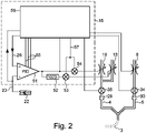
- Controller 16 specifically includes PID controller 51, subtractor 52, multipliers 53 and 54, and breath controller 56. Although PID controller 51, subtractor 52, and multipliers 53 and 54 are shown as components, those skilled in the art will appreciate that in modern controls these functionalities are implemented in software.
- the PID controller 51 delivers a value between a minimum value of, for example, 0 and a maximum value of, for example, 1023.
- the subtractor 52 delivers a second value which, when added to the value of the PID controller, gives the maximum value.
- the value of the PID controller and the second value are each multiplied by an inspiration value 57 in the multipliers 53 and 54, respectively.
- the results of the multipliers 53 and 54 control the proportional valves 13 and 10, respectively.
- the total inspiration flow which is measured via the flow sensor 31, can thus be set via the inspiration value 57 largely independently of the oxygen fraction FiO 2 .
- the manipulated variable namely the proportion of oxygen FiO 2
- the target variable of the PID controller 51 is the saturation target value SpO 2M 26 and is supplied to the PID controller 51 via the + input.
- the actual value of the oxygen saturation SpO 2 is supplied to the --input of the PID controller.
- the premature baby 2 is part of the controlled system.
- the relationship between the oxygen content FiO 2 and the oxygen saturation SpO 2 is non-linear. It therefore makes sense to change the control parameters 55 of the PID controller 51, i.e. the amplification factors for the proportional, integral and differential components, for example based on the set limits SpO 2O 25 and SpO 2U 28 and the direction of the change in oxygen saturation SpO 2 .
- the connection between the oxygen content FiO 2 and the oxygen saturation SpO 2 depends also depends on the condition of the premature baby, for example whether the premature baby is sleeping or awake. Therefore, further parameters such as the tidal volume in PAV or the oxygen saturation SpO 2 itself can be taken into account.
- FIG. 12 is a flowchart showing important steps in breath control 56 for an invasive form of ventilation with tidal volume monitoring, such as IPPV.
- the inspiration flow V ⁇ i is set
- the ventilation frequency f B is set equal to the set ventilation frequency f B0
- the pressure at the end of expiration (PEE pressure, PEEP) is set equal to the set pressure at the end of expiration (PEEP 0 ).
- the Inspiration IP pressure can also be set to the default value IP 0 .
- step 62 waits until one breath has ended. According to the usual convention, a breath begins with inspiration and ends with expiration. For the invention, however, one could also begin a breath with expiration and end with inspiration. The criteria for when expiration and inspiration end result from the type of ventilation, for example IPPV.
- step 63 the inspiration volume V i and the expiration volume V e are determined. "Determine" in step 63 can only mean reading out.
- the target inspiration volume can be derived from the respiratory minute volume V ⁇ ⁇ and the ventilation frequency f B can be calculated. The individual measured respiratory flow values are also added up during expiration so that the expiratory volume V e can be read out at the end of expiration.
- step 68 it is checked whether the measured oxygen saturation SpO 2 falls below the set lower limit value SpO 2U after the EFE event within the EFE event duration t ED . If this is the case, then in step 68 the PEEP is increased by a pressure factor p fr previously set by the user, for example 10%.
- the pressure of the inspiration IP can be increased by a factor p i in order to keep the amount of gas exchanged constant.
- the user can also set a fixed pressure value by which the PEE pressure must be increased. This also applies to the pressure of inspiration.
- the order of the comparisons 66 and 67 can also be reversed.
- the ventilation frequency f B can be increased in step 69 .
- Step 70 is reached if comparisons 66 or 67 return no.
- comparison 70 it is checked whether the oxygen saturation SpO 2 exceeds the saturation target value SpO 2M . If not, step 62 waits for the end of the next breath. If the oxygen saturation SpO 2 exceeds the saturation target value SpO 2M , the PEEP is returned step by step to the original value, dividing by the pressure factor p fl in each step.
- the pressure factors p fr and p fl can be the same, but it makes sense that p fl is smaller than p fr , so that the PEEP decreases more slowly than the previous increase.
- One of these steps is shown in step 71.
- step 77 If the pressure of the inspiration IP was raised in step 77, it is lowered in step 78 in the same way, either by dividing it by p i or subtracting a fixed pressure difference.
- comparison 72 it is checked whether the PEEP has already fallen below the set pressure at the end of the expiration PEEP 0 . If this is the case, the PEEP is set to PEEP 0 in allocation 73 . If the ventilation frequency f B was also changed when the PEEP was adjusted, this is also returned to the set ventilation frequency f B0 in a similar way in the assignments 74 and 76 and in the comparison 75 . If the inspiration IP pressure was increased in step 77, in step 79 it is set equal to the default value IPo.
- step 62 the end of the next breath is awaited.
- Figures 4 to 6 show a flow chart for the regulation according to the invention for a non-invasive form of ventilation with a set apnea duration t A , for example CPAP or SNIPPV.
- the intensity of the ventilation ie in particular the ventilation frequency f B
- the ventilation frequency f B at level 1 is the set ventilation frequency f B0 .
- the ventilation frequency decreases by 2/3 from backup level to backup level.
- the ventilation frequencies for levels 2 and 3 are therefore 2/3 (approx. 66%) f B0 and 4/9 (approx. 44%) f B0 .
- FCBU Frequency Controlled Back-Up
- step 81 If no breath was detected within the apnea duration t A in step 81, ie an apnea is present, the variable BuBySpO 2 is set to 0 in step 83 and the reason for the start of the backup ventilation is thus stored.
- step 82 the backup ventilation is started with the set ventilation frequency f B0 in backup level 1.
- a synchronized form of ventilation eg SNIPPV, is used as backup ventilation.
- step 84 the earliest possible end of the stage t BE is calculated as the sum of the current time t and the minimum dwell time t B .
- step 87 the end of the minimum residence time is awaited.
- step 85 the fully set ventilation frequency f B0 is reduced by 1/3 in step 89 to about 66% with activated FCBU (comparison 86), ie continued in backup level 2. If no spontaneous respiration is detected in step 85, backup ventilation is continued in steps 83 and 82 at frequency f B0 . It follows that the duration of backup stage 1 is n*t BE if t BE >0, where n is an integer. If spontaneous breathing was determined in step 85, the backup ventilation is continued in stage 2 and in step 89 the new ventilation frequency is calculated and set. When the FCBU is activated, ie t B >0, the time t BE is again determined in step 88 after comparison 86 . In step 115 the process is awaited.
- backup ventilation is ended 117 jumped.
- step 91 the end of the minimum residence time t BE is calculated, in step 92 the minimum residence time is awaited.
- step 85 If the oxygen saturation SpO 2 in comparison 90 is below the lower limit value of oxygen saturation SpO 2U , spontaneous breathing has been detected in step 85 and FCBU is activated in step 86, the minimum residence time t B begins again in step 88 . This is achieved in that the end t BE is recalculated in step 88, ie it is shifted into the future.
- comparison 98 In comparison 98, similar to comparison 90, a check is made for the presence of spontaneous breathing or for the SpO 2 oxygen saturation falling below the SpO 2U limit value. As in many programming languages, " ⁇ " stands for a logical or operator and "! for a negation. If there is no spontaneous respiration in comparison 98 or if the SpO 2U limit value has not been reached, a switch is made to comparison 85 . A lack of spontaneous breathing in comparison 85 leads to entry into backup stage 1 via steps 83 and 82.
- comparison 99 Under SNIPPV, which is checked in comparison 99, the next backup level 4 is switched to without changing the frequency. If comparison 99 showed that not SNIPPV but CPAP was selected as the form of ventilation, comparison 100 checks whether the oxygen saturation has reached the saturation target value SpO 2M . If this is not the case, control remains in backup stage 3 and continues with the calculation of the new earliest end t BE in step 91 .
- the new earliest end t BE is then calculated in step 102, and the end t BE is awaited in step 101.
- comparison 106 it is checked again whether spontaneous breathing is present and the oxygen saturation has not fallen below the SpO 2U limit value. If one of the two conditions is not met, then, as before after comparison 98, a jump is made back to comparison 85.
- comparison 108 also checks whether the oxygen saturation SpO 2 has reached the saturation target value SpO 2M . If not, then the backup remains at backup level 4, continuing with comparison 106. If it was established in comparison 108 that the oxygen saturation SpO 2 has reached the saturation target value SpO 2M , then there is a changeover to backup level 5 and in step 113 ventilation frequency f B is lowered to 0.19 ⁇ f B0 .
- the earliest end t BE of stage 5 is calculated in backup stage 5 in step 110 and this end is awaited in step 109 .
- comparison 114 it is again checked whether there is spontaneous breathing and whether the oxygen saturation SpO 2 is at least equal to the SpO 2U limit value. If there is no spontaneous respiration or if the oxygen saturation has fallen below the SpO 2U limit value, a change is made to step 85 . If there is spontaneous breathing and the oxygen saturation is at least equal to the SpO 2U limit value, the backup is ended in step 117 .
- step 95 checks whether the oxygen saturation SpO 2 is below the lower oxygen saturation limit value SpO 2U . If this is not the case either, the breath controller 56 can wait and then check again in step 81 whether an apnea is present. If the oxygen saturation SpO 2 in comparison 95 is below the lower limit of the oxygen saturation SpO 2U , the backup ventilation is started in step 96 with a ventilation frequency f B of 2/3, i.e. about 66%, of the set ventilation frequency f B0 in the backup Stage 2 started.
- the sequence of process steps is identical to that for backup ventilation triggered by an apnea in comparison 81.
- step 81 also runs during the backup ventilation. Should apnea occur in the higher backup levels, steps 83 and 82 go to backup level 1. This can occur especially in the higher backup levels from level 3 onwards.
Description
Das Gebiet der Erfindung sind Beatmungsgeräte der im Oberbegriff des Patentanspruchs 1 genannten Art. Solche Beatmungsgeräte sind aus der
Die Erfindung bezieht sich insbesondere auf Beatmungsgeräte, die die durch ein Oxymeter gemessene Sauerstoffsättigung im Blut berücksichtigen.More particularly, the invention relates to ventilators that take into account blood oxygen saturation as measured by an oximeter.
Beatmungsgeräte zur maschinellen künstlichen Beatmung bei allen Formen des Sauerstoffmangelzustands sind bekannt (Roche Lexikon Medizin, 4. Auflage, Urban & Fischer Verlag, München). Solche Beatmungsgeräte werden auch als Respiratoren bezeichnet. Dabei wird zwischen drei Grundtypen unterschieden:
- a) druckgesteuerte Beatmungsgeräte: die Inspirationsphase ist beendet, wenn im Gerät ein vorgegebener Beatmungsdruck erreicht ist. Die Exspiration erfolgt meist passiv.
- b) volumengesteuerte Beatmungsgeräte: die Inspiration ist beendet, wenn ein vorher eingestelltes Gasvolumen den Respirator verlassen hat. Die Exspiration erfolgt meist passiv.
- c) zeitgesteuerte Beatmungsgeräte: das Gasgemisch wird innerhalb einer vorher eingegebenen Zeit abgegeben.
- a) pressure-controlled ventilators: the inspiration phase ends when a specified ventilation pressure is reached in the device. Expiration is mostly passive.
- b) volume-controlled ventilators: inspiration is terminated when a preset volume of gas has left the ventilator. Expiration is mostly passive.
- c) timed ventilators: the gas mixture is delivered within a previously entered time.
Beatmungsgeräte neueren Typs verfügen über elektronische Steuerungen, die patientengerechte Beatmungstypen erlauben. Solche Beatmungsgeräte weisen häufig einen Drucksensor auf, mit dem der Beatmungsdruck gemessen wird. Der Drucksensor kann sich im Beatmungsgerät befinden und so den Druck am beatmungsgerätseitigen Ende des Beatmungsschlauches messen.Newer types of ventilators have electronic controls that allow patient-specific ventilation types. Such ventilators often have a pressure sensor with which the ventilation pressure is measured. The pressure sensor can be located in the ventilator and thus measure the pressure at the end of the ventilation hose on the ventilator side.
Zusätzlich dürften die meisten elektronisch gesteuerten Beatmungsgeräte auch einen Flusssensor zur Messung des Luftflusses V̇, also des pro Zeiteinheit ein- oder ausgeatmetem Luftvolumens aufweisen. Ein solcher Flusssensor wird auch als Spirometer bezeichnet. Durch Aufsummieren der vom Flusssensor gelieferten Flusswerte während einer Inspirations- oder Exspirationsphase erhält man Inspirations- bzw. Exspirationsvolumina. Mathematisch etwas feiner ausgedrückt ergibt sich ein Inspirations- oder Exspirationsvolumen als Integral über den Atemfluss V̇ über die Zeit einer Inspirations- bzw. ExspirationsphaseIn addition, most electronically controlled ventilators should also have a flow sensor for measuring the air flow V̇, i.e. the volume of air inhaled or exhaled per unit of time. Such a flow sensor is also referred to as a spirometer. Inspiration or expiration volumes are obtained by summing up the flow values supplied by the flow sensor during an inspiration or expiration phase. Expressed mathematically more precisely, an inspiration or expiration volume results as an integral over the respiratory flow V̇ over the time of an inspiration or expiration phase
In Kenntnis des Luftflusses lässt sich der Druckabfall am Beatmungsschlauch (vgl.
Die CPAP-Beatmung (Continuous Positive Airway Pressure) ist eine Beatmungsform, die die Spontanatmung des Patienten mit einem dauerhaften Überdruck von typischerweise 5 bis 30 mbar kombiniert. Der Patient kann seine Atemtiefe, Atemfrequenz und auch den Atemfluss V̇ selbst bestimmen. Wie man Atemzüge unter CPAP erkennt, ist beispielsweise in der
IPPV (Intermittent Positive Pressure Ventilation, deutsch: Beatmung mit pulsierend positivem Druck) wird in der Intensiv- und Notfallmedizin eingesetzt und bezeichnet eine volumenkontrollierte Form der Beatmung mit einem Beatmungsgerät. Synonym zur Abkürzung IPPV wird heute häufiger der Begriff Volume Controlled Ventilation verwendet und mit VCV abgekürzt. Bei einer volumenkontrollierten Beatmung versucht das Beatmungsgerät das Volumen konstant zu halten und variiert dafür den Beatmungsdruck. Bei dieser Beatmungsform kann der Luftdruck in den Atemwegen am Ende der Ausatmung (Exspiration) auf bis zu 0 mbar absinken, erreicht jedoch keine negativen Werte.IPPV (Intermittent Positive Pressure Ventilation) is used in intensive care and emergency medicine and describes a volume-controlled form of ventilation with a ventilator. Synonymous with the abbreviation IPPV, the term Volume Controlled Ventilation is used more frequently today and is abbreviated to VCV. With volume-controlled ventilation, the ventilator tries to keep the volume constant and varies the ventilation pressure to do so. With this form of ventilation, the air pressure in the airways at the end of exhalation (expiration) can drop to as little as 0 mbar, but does not reach negative values.
Häufiger wird heute die druckkontrollierte Beatmungsform genutzt. Sie gibt zwei unterschiedliche Druckniveaus vor: eines für die Einatmung und eines für die Ausatmung. Man nennt diese Beatmungsform auch Bilevel oder BIPAP (Bi Positive Airway Pressure, deutsch: 2 Atemwegsüberdruck). Bei BIPAP herrscht auch am Ende der Exspiration noch ein Überdruck (PEEP, Positive End-Exspiratory Pressure) in den Atemwegen.The pressure-controlled form of ventilation is used more frequently today. It specifies two different pressure levels: one for inhalation and one for exhalation. This type of ventilation is also called Bilevel or BIPAP (Bi Positive Airway Pressure). With BIPAP, there is still overpressure (PEEP, positive end-expiratory pressure) in the airways at the end of expiration.
Die IPPV findet man überwiegend im Bereich des Rettungsdienstes, da auf den hier vorgehaltenen Fahrzeugen nur Notfallrespiratoren eingesetzt werden, welche meist keine anderen Beatmungsformen unterstützen.IPPV is mainly found in the area of emergency services, since only emergency respirators are used on the vehicles provided here, which usually do not support any other forms of ventilation.
Bei der S-IPPV (Synchronized Intermittent Positive Pressure Ventilation) handelt es sich um eine synchronisierte IPPV. Hier werden Atembemühungen des Patienten ("Trigger") erkannt und synchronisiert. Daneben gibt es die SNIPPV, wobei das N für non-invasive oder nicht-invasiv, also für Verwendung einer Beatmungsmaske, einer Nasenbrille oder einem ähnlichen Patienteninterface ohne Trachealkanüle oder Endotrachealtubus steht.S-IPPV (Synchronized Intermittent Positive Pressure Ventilation) is a synchronized IPPV. The patient's breathing efforts ("triggers") are recognized and synchronized here. There is also SNIPPV, where the N stands for non-invasive or non-invasive, i.e. for the use of a ventilation mask, nasal cannula or a similar patient interface without a tracheal cannula or endotracheal tube.
PAV (Proportional Assist Ventilation) ist eine Beatmungsform, in der das Beatmungsgerät einen bestimmten Anteil der für die Atemtätigkeit notwendigen Arbeit übernimmt. Das Beatmungsgerät verändert das Atemvolumen und den Druck in Abhängigkeit der Atemtätigkeit des Patienten. Je stärker der Patient atmet, desto mehr Atemvolumen und Druck liefert das Beatmungsgerät.PAV (Proportional Assist Ventilation) is a form of ventilation in which the ventilator takes over a certain proportion of the work required for breathing. The ventilator changes the tidal volume and pressure depending on the patient's breathing activity. The harder the patient breathes, the more tidal volume and pressure the ventilator delivers.
Bei Unreifgeborenen gibt es einen Reflex, die Atemtätigkeit einzustellen, wenn die Sauerstoffsättigung zu tief ist. Die Kontrolle der Sauerstoffsättigung SpO2 des Blutes durch Veränderung der Sauerstoffkonzentration des dem Patienten zugeführten Atemgases FiO2 ist eine im Stand der Technik beschriebene Vorgehensweise bei der Beatmung von Patienten mit Atemstörungen. Das Verfahren ist z.B. in "
In "
Die
Die
Die
Die in der
Die in der
Es ist Aufgabe der Erfindung, ein Beatmungsgerät sowie ein Steuerverfahren hierfür anzugeben, bei dem die Gefahr der Lungenschädigung gering ist.It is the object of the invention to specify a ventilator and a control method for this in which the risk of lung damage is low.
Diese Aufgabe wird durch die Lehre der unabhängigen Ansprüche gelöst.This object is solved by the teaching of the independent claims.
Bevorzugte Ausführungsformen der Erfindung sind Gegenstand der Unteransprüche.
Im Folgenden werden bevorzugte Ausführungsformen der Erfindung unter Bezugnahme auf die beiliegenden Zeichnungen näher erläutert. Dabei zeigen:
-
Fig. 1 ein erfindungsgemäßes Beatmungssystem; -
Fig. 2 eine optionale Regelschleife zur Steuerung des Sauerstoffanteils in der Atemluft; -
Fig. 3 ein Flussdiagramm für die erfindungsgemäße Regelung bei invasiver Beatmung; und -
Fig. 4 ein Flussdiagramm für die erfindungsgemäße Regelung bei nicht-invasiver Beatmung.bis 6
-
1 a ventilation system according to the invention; -
2 an optional control loop for controlling the percentage of oxygen in the breathing air; -
3 a flow chart for the regulation according to the invention for invasive ventilation; and -
Figures 4 to 6 a flow chart for the regulation according to the invention for non-invasive ventilation.
Falls das Beatmungsgerät 1 ein Intensivrespirator ist, ist er üblicherweise an eine Krankenhausgasversorgung angeschlossen, die beispielhaft als Sauerstoffflasche 12 und Gasflasche 15 dargestellt ist. Die Gasflaschen können aber auch real sein und neben oder, bei geeigneter Bauweise, im Beatmungsgerät untergebracht sein. Sauerstoffflasche 12 ist an Anschluss 11 und Gasflasche 15 an Anschluss 14 angeschlossen. Ein Intensivrespirator wird also üblicherweise über den Anschluss 11 mit medizinischem Sauerstoff und über den Anschluss 14 mit medizinischer Druckluft versorgt. Luft gelangt vom Anschluss 14 über ein Proportionalventil 13 zum Anschluss 29. Zusätzlich oder alternativ zu Gasflasche 15 und Anschluss 14 kann über ein Gebläse 8 Frischluft über eine Öffnung 9 im Beatmungsgerät 1 angesaugt und über ein Ventil 7 über einen Anschluss 29 in den Beatmungsschlauch 4 geblasen werden. Die Luft aus der Gasflasche 15 oder der Krankenhausluftversorgung ist steril. Dies ist bei der durch die Öffnung 9 angesaugten Umgebungsluft schwieriger sicherzustellen. Die Sauerstoffflasche 12 ist optional. Sie dient dazu, den Sauerstoffanteil des Atemgases FiO2 definiert anzuheben. Der Sauerstoff wird über den Anschluss 11 und das Proportionalventil 10 über den Anschluss 29 dem Beatmungsschlauch 4 zugeführt. Der Sauerstoffgehalt in der Sauerstoffflasche 12 liegt im Allgemeinen deutlich über 21% und kann bis nahezu 100% betragen.If the
In anderen Ausführungsformen ist das Gebläse 8 sowie das Ventil 7 durch je ein Proportionalventil, nämlich einem Inspirationsventil und einem Exspirationsventil vor den Sensoren 34 bzw. 35 ersetzt.In other embodiments, the
Die Proportionalventile 10, 13 und 6, das Ventil 7 sowie das Gebläse 8 bzw. die alternativen Proportionalventile sind elektrisch mit der Steuerung 16 verbunden und werden von der Steuerung 16 gesteuert. Durch die Drehzahl des Gebläses 8 bzw. der Öffnungsweite des Inspirationsventils und die Stellung der Ventile 6, 7, 10 und 13 wird sichergestellt, dass während einer Inspirationsphase frische Atemluft durch den Beatmungsschlauch 4 dem Frühgeborenen 2 zugeführt und während einer Exspirationsphase ausgeatmete Luft durch den Beatmungsschlauch 5 abgeführt wird.The
Damit das Beatmungsgerät 1 das Frühgeborene 2 im Hinblick auf seine Atemtätigkeit optimal unterstützen kann, muss das Beatmungsgerät 1 Eigenatmung des Frühgeborenen 2 erkennen und die Beatmung an den Bedarf des Patienten anpassen, ohne dass eine Hyper- oder Hypoventilation vorliegt. Da Frühgeborene 2 und auch Neugeborene ausgesprochene "Bauchatmer" sind, kann man die Atemtätigkeit in vorteilhafter Weise über einen am Bauch angebrachten Sensor, beispielsweise eine Grasby-Kapsel 17 erfassen, wie das in der
Der Druck in der Grasby-Kapsel 17 und damit auch das vom Drucksensor 21 gelieferte elektrisches Signal steigt monoton mit dem Lungenvolumen näherungsweise linear an. Das nichtlinearste Element dürfte die Grasby-Kapsel 17 selbst sein. Das Inspirationsvolumen während eines Atemzugs ergibt sich als Kalibrierungsfaktor mal Differenz zwischen dem maximalen Druck am Ende der Insufflation und dem minimalen Druck am Anfang der Insufflation. Das Exspirationsvolumen während eines Atemzugs ergibt sich als Kalibrierungsfaktor mal Differenz zwischen dem minimalen Druck am Ende der Exhalation und dem maximalen Druck am Anfang der Exhalation. Da die erfindungsgemäße Steuerung lediglich auf Quotienten von Exspirationsvolumen geteilt durch Inspirationsvolumen abstellt, braucht der Kalibrierungsfaktor nicht bestimmt zu werden. Insofern kann man die Differenz zwischen dem Druck zur Zeit t in der Grasby-Kapsel 17 und dem minimalen Druck während der entsprechenden Atemphase als Lungenvolumensignal zur Zeit t bezeichnen.The pressure in the
Ein Lungenvolumensignal lässt sich alternativ auch aus dem ein- und ausgeatmetem Luftfluss V̇ bestimmen. Um diese Luftflüsse zu bestimmen können die Flusssensoren 35 bzw. 34 vorgesehen sein, die mit der Steuerung 16 elektrisch verbunden sind, um der Steuerung die Flussmesswerte mitzuteilen. Alternativ oder ergänzend kann sich auch ein patientennaher Flusssensor an dem Patientenanschluss 37 befinden, der elektrisch oder pneumatisch über den Anschluss 38 mit der Steuerung 16 verbunden ist und den Fluss vorzeichenrichtig misst. Um den Atemfluss im Mund und der Luftröhre des Frühgeborenen 2 zu berechnen, wird das Signal des Flusssensors 34 vom Signal des Flusssensors 35 abgezogen. Dabei wird der Fluss in Richtung dem Frühgeborenen 2 positiv und vom Frühgeborenen weg negativ angesehen. Der Atemfluss im Mund und der Luftröhre des Frühgeborenen 2 kann ebenfalls als Atemsignal angesehen werden. Um aus dem Atemfluss im Mund ein Inspirations- und Exspirationsvolumen während eines Atemzugs zu bestimmen, muss man die einzelnen Messwerte des Gesamtflusses während der Inspirations- bzw. Exspirationsphase aufsummieren. Um aus dem Gesamtfluss ein Lungenvolumensignal zum Zeitpunkt t zu erhalten addiert man alle Gesamtflussmesswerte ab einem Zeitpunkt to bis zum Zeitpunkt t. to wird sinnvollerweise auf den Anfang einer Inspirationsphase gelegt.Alternatively, a lung volume signal can also be determined from the inhaled and exhaled air flow V̇. In order to determine these air flows, the
Überwacht man die Summe der Flusswerte während einer Inspirationsphase, kann man die Inspirationsphase beenden, wenn die Summe einen Schwellenwert, z.B. 0,5 I überschreitet, und so ein bestimmtes Inspirationsvolumen garantieren. Tatsächlich liegen die Flusswerte zunächst als Integer-Werte, die nicht in l/s geeicht sind in der Steuerung vor. Um Rechenzeit zu sparen, ist es sinnvoll, den Schwellenwert in I unter Berücksichtigung der Samplingrate von 100 Hz bis 1 kHz in einen Integer-Grenzwert für die Summe der Flusswerte umzurechnen.If one monitors the sum of the flow values during an inspiration phase, one can end the inspiration phase when the sum exceeds a threshold value, e.g. 0.5 l, and thus guarantee a certain inspiration volume. In fact, the flow values are initially available in the controller as integer values that are not calibrated in l/s. In order to save computing time, it makes sense to convert the threshold value in I into an integer limit value for the sum of the flux values, taking into account the sampling rate of 100 Hz to 1 kHz.
Schließlich sind optional zwei Drucksensoren 31 und 32 vorgesehen, um den Luftdruck nahe bei den Anschlüssen 29 bzw. 30 zu messen. In Kenntnis der von den Flusssensoren 34 und 35 gemessenen Luftflüsse lässt sich der Luftdruck überall in den Beatmungsschläuchen 4 und 5 und dem Endotrachealschlauch 3 berechnen. Alternativ kann ein Drucksensor den Druck an dem Patientenanschluss 37 erfassen.Finally, two
Wichtig für die Regelung ist noch, dass die Steuerung 16 über ein Oxymeter 22 die Sauerstoffsättigung SpO2 im Blut des Frühgeborenen 2 messen kann. Das Oxymeter 22 ist über den Anschluss 23 und ein Kabel elektrisch mit der Steuerung 16 verbunden.It is also important for the regulation that the
Das Beatmungsgerät 1 umfasst schließlich eine Benutzerschnittstelle mit einem Eingabesystem 24 wie z. B. eine Tastatur für die Eingabe von Beatmungsparametern sowie eine Anzeige 36 zum Anzeigen von Beatmungsparametern sowie von Messwerten. Sowohl das Eingabesystem 24 als auch die Anzeige 36 sind elektrisch mit der Steuerung 16 verbunden. Insbesondere kann ein Benutzer einen oberen Grenzwert SpO2O 25 sowie einen unteren Grenzwert SpO2U 27 für die Sauerstoffsättigung SpO2 eingeben. Hieraus berechnet die Steuerung 16 das arithmetische Mittel SpO2M, das als Sättigungszielwert 26 bezeichnet wird. Der Sättigungszielwert 26 kann, muss aber nicht angezeigt werden. In einer anderen Ausführungsform kann der Sättigungszielwert 26 auch vom Benutzer eingegeben und damit unabhängig von dem unteren und oberen Grenzwert SpO2U 27 bzw. SpO2U 27 gewählt werden. Beispielhaft für andere Beatmungsparametern ist der von der Steuerung gewählte Druck am Ende der Exspiration PEEP 28, der eingestellte Druck am Ende der Exspiration PEEP0, der Inspirationsfluss V̇i, die eingestellte Beatmungsfrequenz fB0, die Beatmungsfrequenz fB, das Atemminutenvolumen ![]()
![]()
Die Steuerung 16 kann einen Prozessor zur Ausführung von Software, Arbeitsspeicher, einen nicht flüchtigen Speicher, Analog-Digital-Wandler, Digital-Analog-Wandler sowie Leistungselektronik aufweisen. Der exakte elektrische Aufbau der Steuerung 16 kann von einem Fachmann entworfen werden und liegt im Rahmen seines Fachwissens.The
Anhand des Blockschaltbilds in
Die Zielgröße des PID Reglers 51 ist der Sättigungszielwert SpO2M 26 und wird dem PID-Regler 51 über den +-Eingang zugeführt. Die Istgröße der Sauerstoffsättigung SpO2 wird dem --Eingang des PID-Reglers zugeführt.The target variable of the
Im Betrieb ist das Frühgeborene 2 Teil der Regelstrecke. Der Zusammenhang zwischen dem Sauerstoffanteil FiO2 und der Sauerstoffsättigung SpO2 ist nichtlinear. Deshalb ist es sinnvoll, die Regelparameter 55 des PID-Reglers 51, also die Verstärkungsfaktoren für den Proportional-, Integral- und Differenzialanteil beispielsweise anhand der eingestellten Grenzen SpO2O 25 und SpO2U 28 sowie der Richtung der Änderung der Sauerstoffsättigung SpO2 zu ändern. Der Zusammenhang zwischen dem Sauerstoffanteil FiO2 und der Sauerstoffsättigung SpO2 hängt auch vom Zustand des Frühgeborenen ab, also beispielsweise davon, ob das Frühgeborene schläft oder wach ist. Deshalb können weitere Parameter wie das Atemzugvolumen bei PAV oder die Sauerstoffsättigung SpO2 selbst berücksichtigt werden.In operation, the
In Schritt 63 werden das Inspirationsvolumen Vi und das Exspirationsvolumen Ve bestimmt. "Bestimmen" in Schritt 63 kann lediglich Auslesen bedeuten. Insbesondere bei der IPPV kann das Sollinspirationsvolumen aus dem Atemminutenvolumen ![]()
![]()
Im Vergleich 64 wird das Exspirationsvolumen mit dem Inspirationsvolumen verglichen. Übersteigt das Exspirationsvolumen das Inspirationsvolumen um wenigstens 50 %, ist also Ve/Vi >=1,5, so wird in Schritt 65 ein EFE-Ereignis gespeichert, beispielsweise, in dem eine Endzeit tE als Summe aus der aktuellen Zeit t plus einer vorgegebenen oder einstellbaren EFE-Ereignisdauer tED berechnet und gespeichert wird. In einer anderen Ausführungsform kann ein von 50% abweichender Schwellenwert vom Bedienpersonal eingestellt werden. tED beträgt mindestens einen Atemzug und ist sinnvollerweise länger und vom Benutzer einstellbar. Der Ablauf der EFE-Ereignisdauer tED wird im Vergleich 66 überprüft. Dies geschieht je nach dem Ergebnis im Vergleich 64 unmittelbar nach Vergleich 64 oder Schritt 65. In Vergleich 67 wird geprüft, ob nach dem EFE-Ereignis innerhalb der EFE-Ereignisdauer tED die gemessene Sauerstoffsättigung SpO2 unter den eingestellten unteren Grenzwert SpO2U fällt. Ist das der Fall, so wird der PEEP in Schritt 68 um einen vorher vom Anwender eingestellten Druckfaktor pfr, beispielsweise 10%, erhöht. Fakultativ kann kurz davor oder danach, also etwa zur gleichen Zeit in Schritt 77 der Druck der Inspiration IP um einen Faktor pi angehoben werden, um die Menge an ausgetauschtem Gas konstant zu halten. Anstelle eines Faktors kann der Anwender auch einen festen Druckwert einstellen, um den der PEE-Druck erhöht werden muss. Dies gilt auch für den Druck der Inspiration. Die Reihenfolge der Vergleiche 66 und 67 kann auch vertauscht werden. Um die Menge an ausgetauschtem Gas in dieser adaptierten Phase der Beatmung konstant zu halten kann die Beatmungsfrequenz fB in Schritt 69 erhöht werden.In
Zum Schritt 70 gelangt man, wenn die Vergleiche 66 oder 67 nein liefern. In Vergleich 70 wird geprüft, ob die Sauerstoffsättigung SpO2 den Sättigungszielwert SpO2M überschreitet. Falls dies nicht der Fall ist, wird in Schritt 62 auf das Ende des nächsten Atemzugs gewartet. Überschreitet die Sauerstoffsättigung SpO2 den Sättigungszielwert SpO2M, so wird der PEEP schrittweise auf den ursprünglichen Wert zurückgeführt, wobei in jedem Schritt um den Druckfaktor pfl dividiert wird. Die Druckfaktoren pfr und pfl können gleich sein, aber sinnvollerweise ist pfl kleiner als pfr, so dass die Absenkung des PEEP langsamer als die vorherige Anhebung erfolgt. Einer dieser Schritte ist in Schritt 71 dargestellt. Wenn der Druck der Inspiration IP in Schritt 77 angehoben wurde, wird er in Schritt 78 in gleicher Weise, also entweder durch Division durch pi oder subtrahieren einer festen Druckdifferenz abgesenkt. In Vergleich 72 wird geprüft, ob der PEEP schon unter den eingestellten Druck am Ende der Exspiration PEEP0 gefallen ist. Ist dies der Fall, wird in Zuweisung 73 der PEEP auf den PEEP0 gesetzt. Wurde die Beatmungsfrequenz fB bei der Anpassung des PEEP ebenfalls geändert, so wird auch diese auf ähnliche Weise in den Zuweisungen 74 und 76 sowie im Vergleich 75 wieder auf die eingestellte Beatmungsfrequenz fB0 zurückgeführt. Wenn der Druck der Inspiration IP in Schritt 77 angehoben wurde, wird er in Schritt 79 gleich dem Standardwert IPo gesetzt.
Im Anschluss an die Zuweisungen 69 oder 76 oder den Vergleich 75 wird in Schritt 62 auf das Ende des nächsten Atemzugs gewartet.Following the
Falls in Schritt 81 innerhalb der Apnoe-Dauer tA kein Atemzug erkannt wurde, also eine Apnoe vorliegt, wird in Schritt 83 die Variable BuBySpO2 auf 0 gesetzt und so der Grund für den Start der Backup-Beatmung gespeichert. In Schritt 82 wird die Backup-Beatmung mit der eingestellten Beatmungsfrequenz fB0 in Backup-Stufe 1 gestartet. Als Backup-Beatmung wird eine synchronisierte Beatmungsform, z.B. SNIPPV, verwendet. In Schritt 84 wird das frühestmögliche Ende der Stufe tBE als Summe aus der aktuellen Zeit t und der Mindestverweildauer tB berechnet. In Schritt 87 wird das Ende der Mindestverweildauer abgewartet.If no breath was detected within the apnea duration t A in
Falls in Schritt 85 Spontanatmung erkannt wird, wird bei aktiviertem FCBU (Vergleich 86) die volle eingestellte Beatmungsfrequenz fB0 um 1/3 in Schritt 89 auf etwa 66% reduziert, also in Backup-Stufe 2 fortgesetzt. Falls in Schritt 85 keine Spontanatmung erkannt wird, wird die Backup-Beatmung mit der Frequenz fB0 in den Schritten 83 und 82 fortgesetzt. Hieraus ergibt sich, dass die Dauer der Backup-Stufe 1 n*tBE beträgt, wenn tBE>0, wobei n eine ganze Zahl ist. Wurde in Schritt 85 eine Spontanatmung festgestellt, so wird die Backup-Beatmung in Stufe 2 fortgesetzt und in Schritt 89 die neue Beatmungsfrequenz berechnet und eingestellt. Bei aktiviertem FCBU, also tB>0, wird nach Vergleich 86, in Schritt 88 neuerlich die Zeit tBE bestimmt. In Schritt 115 wird deren Ablauf abgewartet. Ist FCBU in Vergleich 86 nicht aktiviert und liegt die Sauerstoffsättigung in Vergleich 94 über dem unteren Grenzwert SpO2U und wurde die Backup-Beatmung wegen einer Apnoe in Schritt 81 gestartet, ist also BuBySpO2==0, so wird zur Beendigung der Backup-Beatmung 117 gesprungen. Wie in vielen Programmiersprachen steht dabei && für einen logischen Und-Operator und == für einen Vergleichsoperator, der auf Gleichheit prüft.If spontaneous breathing is detected in
Andernfalls wird im Vergleich 90 geprüft, ob die Sauerstoffsättigung SpO2 über dem unteren Grenzwert der Sauerstoffsättigung SpO2U liegt und weiterhin Spontanatmung vorherrscht. Ist dies der Fall, wird die Backup-Beatmung in Schritt 93 in Backup-Stufe 3 mit einer Beatmungsfrequenz fB von 4/9 der eingestellten Beatmungsfrequenz fB0 fortgesetzt. Dann wird in Schritt 91 das Ende der Mindestverweildauer tBE berechnet, in Schritt 92 die Mindestverweildauer abgewartet.Otherwise, it is checked in
Liegt die Sauerstoffsättigung SpO2 bei Vergleich 90 unter dem unteren Grenzwert der Sauerstoffsättigung SpO2U, ist in Schritt 85 Spontanatmung erkannt worden und ist in Schritt 86 FCBU aktiviert, beginnt die Mindestverweildauer tB in Schritt 88 erneut. Dies wird dadurch erreicht, dass in Schritt 88 das Ende tBE neu berechnet, also in die Zukunft verschoben wird.If the oxygen saturation SpO 2 in
In Vergleich 98 wird ähnlich wie in Vergleich 90 auf das Vorhandensein von Spontanatmung oder Unterschreiten des Grenzwertes SpO2U durch die Sauerstoffsättigung SpO2 geprüft. Wie in vielen Programmiersprachen steht dabei "∥" für einen logischen oder-Operator und "!" für eine Negation. Liegt in Vergleich 98 keine Spontanatmung vor oder ist der Grenzwert SpO2U unterschritten, so wird zu Vergleich 85 gewechselt. Eine fehlende Spontanatmung in Vergleich 85 führt zum Eintritt in die Backup-Stufe 1 über die Schritte 83 und 82.In
Unter SNIPPV, was in Vergleich 99 überprüft wird, wird ohne Frequenzwechsel in die nächste Backup-Stufe 4 gewechselt. Zeigte Vergleich 99, dass nicht SNIPPV, sondern CPAP als Beatmungsform gewählt war, so wird in Vergleich 100 geprüft, ob die Sauerstoffsättigung den Sättigungszielwert SpO2M erreicht hat. Ist dies nicht der Fall, verbleibt die Steuerung in Backup-Stufe 3 und fährt mit der Berechnung des neuen frühesten Endes tBE in Schritt 91 fort.Under SNIPPV, which is checked in
Hat die Sauerstoffsättigung SpO2 in Vergleich 100 den Sättigungszielwert SpO2M erreicht, so wird auch unter CPAP in die Backup-Stufe 4 gewechselt und in Schritt 105 die neue Backup-Frequenz fB=0.29×fB0 berechnet und eingestellt. In Stufe 4 wird dann das neue früheste Ende tBE in Schritt 102 berechnet, das Ende tBE in Schritt 101 abgewartet. In Vergleich 106 wird erneut geprüft, ob Spontanatmung vorhanden ist und die Sauerstoffsättigung nicht unter den Grenzwert SpO2U gefallen ist. Sollte eine der beiden Bedingungen nicht erfüllt sein, so wird, wie zuvor nach Vergleich 98, zu Vergleich 85 zurückgesprungen.If the oxygen saturation SpO 2 has reached the saturation target value SpO 2M in
Ist in Vergleich 106 Spontanatmung vorhanden und die Sauerstoffsättigung SpO2 mindestens gleich dem Grenzwert SpO2U, so wird im Falle der Beatmungsform SNIPPV, was in Vergleich 107 geprüft wird, ohne Frequenzwechsel in die Backup-Stufe 5 gewechselt. Ist die Beatmungsform nicht SNIPPV, so wird in Vergleich 108 zusätzlich geprüft, ob die Sauerstoffsättigung SpO2 den Sättigungszielwert SpO2M erreicht hat. Ist dies nicht der Fall, dann verbleibt das Backup in Backup-Stufe 4, wobei mit Vergleich 106 fortgesetzt wird. Wurde im Vergleich 108 festgestellt, dass die Sauerstoffsättigung SpO2 den Sättigungszielwert SpO2M erreicht hat, so wird in die Backup-Stufe 5 gewechselt und in Schritt 113 die Beatmungsfrequenz fB auf 0.19×fB0 abgesenkt. Unabhängig von CPAP oder SNIPPV wird in Backup-Stufe 5 im Schritt 110 wird das früheste Ende tBE der Stufe 5 berechnet und in Schritt 109 dieses Ende abgewartet. Im Vergleich 114 wird wiederum geprüft, ob Spontanatmung vorhanden und die Sauerstoffsättigung SpO2 mindestens gleich dem Grenzwert SpO2U ist. Ist keine Spontanatmung vorhanden oder die Sauerstoffsättigung unter den Grenzwert SpO2U gefallen, so wird zu Schritt 85 gewechselt. Ist Spontanatmung vorhanden und die Sauerstoffsättigung mindestens gleich dem Grenzwert SpO2U so wird das Backup in Schritt 117 beendet.If spontaneous respiration is present in
Falls in Schritt 81 keine Apnoe erkannt wurde, also Spontanatmung vorhanden war oder die Spontanatmung für weniger als die der Apnoe-Dauer tA aussetzte, wird in Schritt 95 geprüft, ob die Sauerstoffsättigung SpO2 unter dem unteren Grenzwert der Sauerstoffsättigung SpO2U liegt. Falls dies auch nicht der Fall ist, kann die Atemzugsteuerung 56 warten und danach in Schritt 81 wieder prüfen, ob eine Apnoe vorliegt. Falls die Sauerstoffsättigung SpO2 in Vergleich 95 unter dem unteren Grenzwert der Sauerstoffsättigung SpO2U liegt, wird die Backup-Beatmung in Schritt 96 mit einer Beatmungsfrequenz fB von 2/3, also etwa 66%, der eingestellten Beatmungsfrequenz fB0 in der Backup-Stufe 2 gestartet. Zuvor wird in Schritt 97 der Einstieg in das Backup über einen Sättigungsabfall, also über Schritt 95, gespeichert, indem die Variable BuBySpO2 =1 gesetzt wird, um den eventuellen vorzeitigen Ausstieg im Vergleich 94 zu verhindern. Im weiteren Verlauf ist die Abfolge der Prozessschritte identisch mit der bei einer Backup-Beatmung, die durch eine Apnoe im Vergleich 81 ausgelöst wurde.If no apnea was detected in
Auch wenn das in den
Claims (4)
- Respirator for ventilating a patient, comprising:a respiratory tube connector (29, 30) for connecting a respiratory tube (4, 5);an actuator (8, 10, 13) that is pneumatically connected to the respiratory tube connector (29, 30) for delivering air to a patient (2) via the respiratory tube connector (29, 30);an oximeter connector (23) for returning an oxygen saturation signal;a digital programmable controller (16) that is electrically connected to said oximeter connector (23) for delivering the oxygen saturation signal to said digital programmable controller (16), wherein the digital programmable controller (16) is programmed• to calculate the oxygen saturation from the oxygen saturation signal, and• to determine whether the oxygen saturation falls below (67) a lower limit (27) and to increase the pressure at the end of exhalation and to increase the respiration rate (68, 69)characterized in thatthe respirator (1) further comprises a valve (13) and an oxygen connector (14) for a gas or mixture of gases (15) having more than 21 volume percent of oxygen, wherein an inlet of the valve (13) is pneumatically connected to the oxygen connector (14), an outlet of the valve (13) is pneumatically connected to the breathing respiratory tube connector (29) and a control connector of the valve (13) is electrically connected to the digital programmable controller (16), wherein the digital programmable controller (16) further comprises a PID controller (51), which controls the valve (13) so that the oxygen saturation differs as little as possible from a saturation setpoint between an upper limit (25) and a lower limit (27).
- Respirator according to claim 1, wherein the digital programmable controller (16) is further programmed to increase the inspiratory pressure together with the pressure at the end of exhalation.
- Respirator according to one of the preceding claims, further characterized in
a breathing sensor connector (19) for a breathing sensor (17, 34, 35) for providing a breathing sensor signal; wherein the digital programmable controller (16) is electrically connected to said breathing sensor connector (19), wherein the breathing signal is fed to said digital programmable controller (16) that is programmed• to calculate a lung volume signal from said breathing signal, wherein the lung volume signal monotonically increases with the lung volume of the patient (2), wherein the digital programmable controller (16) is programmed to calculate an inhaled volume and an exhaled volume from the lung volume signal for each breath; and• to store an EFE event (65) when the exhaled volume exceeds the associated inhaled volume by an adjustable value (64), and to increase the pressure at the end of exhalation at an EFE event (68). - Respirator according to claim 3, further comprisingan oximeter connector (23) that is electrically connected to said digital programmable controller (16) for delivering an oxygen saturation signal;wherein the digital programmable controller (16) further is programmed to determine whether the oxygen saturation falls below (67) a lower limit (27) during a time period after an EFE event and to increase the pressure at the end of exhalation only if the oxygen saturation falls below (67) a lower limit (27) during a time period after an EFE event.
Priority Applications (1)
| Application Number | Priority Date | Filing Date | Title |
|---|---|---|---|
| EP22203061.1A EP4140525A3 (en) | 2015-03-17 | 2016-03-10 | Respirators and control methods for respirators |
Applications Claiming Priority (3)
| Application Number | Priority Date | Filing Date | Title |
|---|---|---|---|
| DE102015103894.3A DE102015103894A1 (en) | 2015-03-17 | 2015-03-17 | Respirators and control methods for ventilators |
| PCT/DE2016/100106 WO2016146102A1 (en) | 2015-03-17 | 2016-03-10 | Respirators and control methods for respirators |
| EP16717238.6A EP3270993B1 (en) | 2015-03-17 | 2016-03-10 | Respirators |
Related Parent Applications (1)
| Application Number | Title | Priority Date | Filing Date |
|---|---|---|---|
| EP16717238.6A Division EP3270993B1 (en) | 2015-03-17 | 2016-03-10 | Respirators |
Related Child Applications (2)
| Application Number | Title | Priority Date | Filing Date |
|---|---|---|---|
| EP22203061.1A Division EP4140525A3 (en) | 2015-03-17 | 2016-03-10 | Respirators and control methods for respirators |
| EP22203061.1A Division-Into EP4140525A3 (en) | 2015-03-17 | 2016-03-10 | Respirators and control methods for respirators |
Publications (3)
| Publication Number | Publication Date |
|---|---|
| EP3653248A2 EP3653248A2 (en) | 2020-05-20 |
| EP3653248A3 EP3653248A3 (en) | 2020-08-05 |
| EP3653248B1 true EP3653248B1 (en) | 2022-12-21 |
Family
ID=55794831
Family Applications (3)
| Application Number | Title | Priority Date | Filing Date |
|---|---|---|---|
| EP20150286.1A Active EP3653248B1 (en) | 2015-03-17 | 2016-03-10 | Respirators |
| EP16717238.6A Active EP3270993B1 (en) | 2015-03-17 | 2016-03-10 | Respirators |
| EP22203061.1A Pending EP4140525A3 (en) | 2015-03-17 | 2016-03-10 | Respirators and control methods for respirators |
Family Applications After (2)
| Application Number | Title | Priority Date | Filing Date |
|---|---|---|---|
| EP16717238.6A Active EP3270993B1 (en) | 2015-03-17 | 2016-03-10 | Respirators |
| EP22203061.1A Pending EP4140525A3 (en) | 2015-03-17 | 2016-03-10 | Respirators and control methods for respirators |
Country Status (6)
| Country | Link |
|---|---|
| EP (3) | EP3653248B1 (en) |
| CN (3) | CN111760140B (en) |
| DE (1) | DE102015103894A1 (en) |
| DK (2) | DK3653248T3 (en) |
| PL (1) | PL3270993T3 (en) |
| WO (1) | WO2016146102A1 (en) |
Families Citing this family (7)
| Publication number | Priority date | Publication date | Assignee | Title |
|---|---|---|---|---|
| EP3950031A1 (en) * | 2017-11-30 | 2022-02-09 | Löwenstein Medical Technology S.A. | System for respiration gas supply |
| US11357939B2 (en) * | 2018-05-18 | 2022-06-14 | Gyrus Acmi, Inc. | Breathing lung device |
| CN109353471A (en) * | 2018-09-28 | 2019-02-19 | 威海威高海盛医用设备有限公司 | A kind of submersible decompression chamber breathing gas converting system |
| CN113260402A (en) * | 2018-12-31 | 2021-08-13 | 皇家飞利浦有限公司 | Method and system for delivering oxygen to a patient |
| CN111135412B (en) * | 2020-01-20 | 2022-01-25 | 深圳市科曼医疗设备有限公司 | Pressure control method and device in breathing machine, breathing machine and storage medium |
| CN112245731B (en) * | 2020-10-19 | 2022-10-11 | 湖南万脉医疗科技有限公司 | Aerator for breathing machine and application thereof |
| CN116870306A (en) * | 2021-03-12 | 2023-10-13 | 天津怡和嘉业医疗科技有限公司 | Respiratory control assembly and ventilation therapy apparatus |
Family Cites Families (38)
| Publication number | Priority date | Publication date | Assignee | Title |
|---|---|---|---|---|
| CN1024114C (en) * | 1989-02-24 | 1994-04-06 | 航天工业部第二研究院第四总体设计部 | Microcomputerized controller of respirator |
| US5388575A (en) * | 1992-09-25 | 1995-02-14 | Taube; John C. | Adaptive controller for automatic ventilators |
| IL118191A (en) * | 1996-05-08 | 2001-04-30 | Card Guard Scient Survival Ltd | Apparatus and method for remote spirometry |
| AU5701498A (en) * | 1996-12-12 | 1998-07-03 | Johns Hopkins University School Of Medicine, The | Method and apparatus for providing ventilatory support to a patient |
| JPH10216114A (en) * | 1997-02-06 | 1998-08-18 | Nippon Colin Co Ltd | Degree of oxygen saturation measuring apparatus |
| ES2242289T3 (en) * | 1997-07-25 | 2005-11-01 | MINNESOTA INNOVATIVE TECHNOLOGIES & INSTRUMENTS CORPORATION (MITI) | CONTROL DEVICE TO SUPPLY SUPPLEMENTARY OXYGEN FOR BREATHING. |
| US20070000494A1 (en) * | 1999-06-30 | 2007-01-04 | Banner Michael J | Ventilator monitor system and method of using same |
| AU2001269349A1 (en) | 2000-06-30 | 2002-01-08 | Northgate Technologies Inc. | Method and apparatus for humidification and warming of air |
| US6512938B2 (en) | 2000-12-12 | 2003-01-28 | Nelson R. Claure | System and method for closed loop controlled inspired oxygen concentration |
| DE10253947C1 (en) | 2002-11-19 | 2003-12-04 | Seleon Gmbh | Pressure loss compensation method for respiration device with calculation of pressure loss from measured air flow |
| US7802571B2 (en) * | 2003-11-21 | 2010-09-28 | Tehrani Fleur T | Method and apparatus for controlling a ventilator |
| US8869795B2 (en) * | 2003-11-26 | 2014-10-28 | Resmed Limited | Methods and apparatus for the sytematic control of ventilatory support in the presence of respiratory insufficiency |
| DE102004006396B4 (en) * | 2004-02-10 | 2021-11-04 | Löwenstein Medical Technology S.A. | Device for ventilation and method for controlling a ventilator |
| WO2006066337A1 (en) * | 2004-12-23 | 2006-06-29 | Resmed Limited | Method for detecting and disciminatng breathing patterns from respiratory signals |
| RU2008107414A (en) * | 2005-09-02 | 2009-10-10 | Текнион Рисерч Энд Дивелопмент Фаундейшн Лтд. (Il) | METHOD AND DEVICE FOR CONTROLING LIGHT VOLUME |
| US20070062533A1 (en) * | 2005-09-21 | 2007-03-22 | Choncholas Gary J | Apparatus and method for identifying FRC and PEEP characteristics |
| DE102006030520B3 (en) * | 2006-07-01 | 2007-06-21 | Dräger Medical AG & Co. KG | Respiratory gas supplying device for patient, has control device that is provided for controlling inspiration pressure based on pulmonary inner pressure and pulmonary target pressure |
| ATE487419T1 (en) * | 2006-11-16 | 2010-11-15 | Hamilton Medical Ag | METHOD AND DEVICE FOR DETERMINING PEEP DURING VENTILATION OF A PATIENT |
| CN101121051A (en) * | 2007-08-10 | 2008-02-13 | 北京新华卫拓医疗器械有限公司 | Method and device for monitoring controlling oxygen inhalation instrument |
| RU2492808C2 (en) * | 2008-02-07 | 2013-09-20 | Конинклейке Филипс Электроникс Н.В. | Device for measurement and prediction of respiratory stability of patients |
| EP2363163A1 (en) * | 2008-03-27 | 2011-09-07 | Nellcor Puritan Bennett LLC | Device for controlled delivery of breathing gas to a patient using multiple ventilation parameters |
| US20090320836A1 (en) * | 2008-06-30 | 2009-12-31 | Baker Jr Clark R | Method For Regulating Treatment Based On A Medical Device Under Closed-Loop Physiologic Control |
| US8302602B2 (en) * | 2008-09-30 | 2012-11-06 | Nellcor Puritan Bennett Llc | Breathing assistance system with multiple pressure sensors |
| DE102009013396B3 (en) * | 2009-03-16 | 2010-08-05 | Dräger Medical AG & Co. KG | Apparatus and method for controlling the oxygen dosage of a ventilator |
| US9333312B2 (en) * | 2009-03-27 | 2016-05-10 | Maquet Critical Care Ab | Peep regulation for a breathing apparatus |
| US8596270B2 (en) * | 2009-08-20 | 2013-12-03 | Covidien Lp | Systems and methods for controlling a ventilator |
| EP2523715B1 (en) * | 2010-01-14 | 2015-09-23 | Koninklijke Philips N.V. | Servo ventilation using negative pressure support |
| EP2525859A1 (en) * | 2010-01-22 | 2012-11-28 | Koninklijke Philips Electronics N.V. | Automatically controlled ventilation system |
| US20110213215A1 (en) * | 2010-02-26 | 2011-09-01 | Nellcor Puritan Bennett Llc | Spontaneous Breathing Trial Manager |
| EP2371410B1 (en) * | 2010-03-29 | 2016-10-12 | General Electric Company | Arrangement and method for ventilating lungs |
| US8554298B2 (en) * | 2010-09-21 | 2013-10-08 | Cividien LP | Medical ventilator with integrated oximeter data |
| US20120090611A1 (en) * | 2010-10-13 | 2012-04-19 | Nellcor Puritan Bennett Llc | Systems And Methods For Controlling An Amount Of Oxygen In Blood Of A Ventilator Patient |
| CN102499694B (en) * | 2011-09-22 | 2013-11-27 | 中国人民解放军第三军医大学野战外科研究所 | Method for eliminating interference to blood oxygen saturation monitoring |
| US9254368B2 (en) * | 2011-12-02 | 2016-02-09 | Drägerwerk AG & Co. KGaA | Oxygen regulation with at least two SPO2 monitors and automatic recognition of a signal having a higher rating |
| DE102012003115A1 (en) * | 2012-02-16 | 2013-08-22 | Dräger Medical GmbH | ventilation system |
| EP2671509A1 (en) | 2012-06-06 | 2013-12-11 | Fritz Stephan GmbH | Method and apparatus for breathing detection and/or breathing assistance |
| CN103893865B (en) * | 2012-12-26 | 2017-05-31 | 北京谊安医疗系统股份有限公司 | A kind of method of lung ventilator turbine volume controlled ventilation |
| CN104399164A (en) * | 2014-12-01 | 2015-03-11 | 北京神鹿腾飞医疗科技有限公司 | Intelligent respirator and aerating method of using the respirator |
-
2015
- 2015-03-17 DE DE102015103894.3A patent/DE102015103894A1/en not_active Withdrawn
-
2016
- 2016-03-10 DK DK20150286.1T patent/DK3653248T3/en active
- 2016-03-10 CN CN202010548886.9A patent/CN111760140B/en active Active
- 2016-03-10 CN CN201680016318.6A patent/CN107405107B/en active Active
- 2016-03-10 EP EP20150286.1A patent/EP3653248B1/en active Active
- 2016-03-10 EP EP16717238.6A patent/EP3270993B1/en active Active
- 2016-03-10 DK DK16717238.6T patent/DK3270993T3/en active
- 2016-03-10 WO PCT/DE2016/100106 patent/WO2016146102A1/en active Application Filing
- 2016-03-10 PL PL16717238T patent/PL3270993T3/en unknown
- 2016-03-10 CN CN202311271779.6A patent/CN117258096A/en active Pending
- 2016-03-10 EP EP22203061.1A patent/EP4140525A3/en active Pending
Also Published As
| Publication number | Publication date |
|---|---|
| CN107405107A (en) | 2017-11-28 |
| EP3270993A1 (en) | 2018-01-24 |
| EP4140525A2 (en) | 2023-03-01 |
| EP3653248A2 (en) | 2020-05-20 |
| WO2016146102A1 (en) | 2016-09-22 |
| CN107405107B (en) | 2020-07-17 |
| DE102015103894A1 (en) | 2016-09-22 |
| CN111760140A (en) | 2020-10-13 |
| PL3270993T3 (en) | 2020-06-29 |
| EP4140525A3 (en) | 2023-05-31 |
| EP3653248A3 (en) | 2020-08-05 |
| CN117258096A (en) | 2023-12-22 |
| DK3270993T3 (en) | 2020-04-06 |
| DK3653248T3 (en) | 2023-03-27 |
| CN111760140B (en) | 2023-11-21 |
| EP3270993B1 (en) | 2020-01-08 |
Similar Documents
| Publication | Publication Date | Title |
|---|---|---|
| EP3653248B1 (en) | Respirators | |
| DE60126694T2 (en) | ventilator | |
| EP2934640B1 (en) | Ventilation system | |
| US7802571B2 (en) | Method and apparatus for controlling a ventilator | |
| DE69721330T2 (en) | Calculation method of a person's instantaneous tidal volume during ventilation | |
| DE69735428T2 (en) | DEVICE FOR VENTILATION DURING ANESTHESIA | |
| DE19880497B4 (en) | Device for automated ventilation by positive air pressure on the respiratory tract | |
| DE102008008823A1 (en) | Setting forced mechanical ventilation parameters based on patient physiology | |
| DE102008014479A1 (en) | Setting the expiratory time in mandatory mechanical ventilation based on a deviation from a steady state of end-tidal gas concentrations | |
| EP3520850A1 (en) | System for detecting a patient's respiratory effort | |
| DE102006032620B3 (en) | Respirator for treatment of obstructive sleep apnea, has controller determining loss pressure, resulting over respiratory tract resistance of tract of patient, and for proportional adjustment of therapy pressure progress | |
| EP0459284B1 (en) | Device for automatically controlling spontaneous breathing assistance | |
| DE102009012146B4 (en) | Method for operating a ventilator | |
| DE102018003026A1 (en) | Ventilation device with a safety valve | |
| DE102010030324A1 (en) | Ventilation aid, ventilator, system and method for non-invasive ventilation of premature babies | |
| EP3964253B1 (en) | Computer program and device for automatically determining the target frequency of a breathing apparatus | |
| DE102022120843A1 (en) | SYSTEM FOR SIMULATING THE BREATHING OF A LIVING BEING | |
| EP3957241A1 (en) | Assembly and method for determining regional lung compliance | |
| EP3115075A1 (en) | Device for varying the breath gas pressure depending on a measure of cardiac output | |
| EP3524306A1 (en) | Artificial respiration device and control and test method | |
| DE102020119085B4 (en) | Ventilation device for ventilating a person, control method for a radial fan of a ventilator and ventilation method | |
| DE102023104211A1 (en) | Device and method for controlling a gas flow | |
| EP0684048B1 (en) | Oxygen therapy device | |
| EP4129377A1 (en) | Ventilator system with speaking function | |
| DE102004046991A1 (en) | Nose mask for use with respirator, has thermopile for collecting airflow caused by mouth respiration |
Legal Events
| Date | Code | Title | Description |
|---|---|---|---|
| PUAI | Public reference made under article 153(3) epc to a published international application that has entered the european phase |
Free format text: ORIGINAL CODE: 0009012 |
|
| STAA | Information on the status of an ep patent application or granted ep patent |
Free format text: STATUS: THE APPLICATION HAS BEEN PUBLISHED |
|
| AC | Divisional application: reference to earlier application |
Ref document number: 3270993 Country of ref document: EP Kind code of ref document: P |
|
| AK | Designated contracting states |
Kind code of ref document: A2 Designated state(s): AL AT BE BG CH CY CZ DE DK EE ES FI FR GB GR HR HU IE IS IT LI LT LU LV MC MK MT NL NO PL PT RO RS SE SI SK SM TR |
|
| RAP1 | Party data changed (applicant data changed or rights of an application transferred) |
Owner name: FRITZ STEPHAN GMBH |
|
| PUAL | Search report despatched |
Free format text: ORIGINAL CODE: 0009013 |
|
| AK | Designated contracting states |
Kind code of ref document: A3 Designated state(s): AL AT BE BG CH CY CZ DE DK EE ES FI FR GB GR HR HU IE IS IT LI LT LU LV MC MK MT NL NO PL PT RO RS SE SI SK SM TR |
|
| RIC1 | Information provided on ipc code assigned before grant |
Ipc: A61B 5/091 20060101ALI20200626BHEP Ipc: A61B 5/08 20060101ALI20200626BHEP Ipc: A61M 16/00 20060101AFI20200626BHEP |
|
| STAA | Information on the status of an ep patent application or granted ep patent |
Free format text: STATUS: REQUEST FOR EXAMINATION WAS MADE |
|
| 17P | Request for examination filed |
Effective date: 20210205 |
|
| RBV | Designated contracting states (corrected) |
Designated state(s): AL AT BE BG CH CY CZ DE DK EE ES FI FR GB GR HR HU IE IS IT LI LT LU LV MC MK MT NL NO PL PT RO RS SE SI SK SM TR |
|
| REG | Reference to a national code |
Ref country code: DE Ref legal event code: R079 Ref document number: 502016015495 Country of ref document: DE Free format text: PREVIOUS MAIN CLASS: A61M0016000000 Ipc: A61M0016120000 |
|
| GRAP | Despatch of communication of intention to grant a patent |
Free format text: ORIGINAL CODE: EPIDOSNIGR1 |
|
| STAA | Information on the status of an ep patent application or granted ep patent |
Free format text: STATUS: GRANT OF PATENT IS INTENDED |
|
| RIC1 | Information provided on ipc code assigned before grant |
Ipc: A61B 5/091 20060101ALI20220420BHEP Ipc: A61B 5/08 20060101ALI20220420BHEP Ipc: A61M 16/00 20060101ALI20220420BHEP Ipc: A61M 16/04 20060101ALI20220420BHEP Ipc: A61M 16/12 20060101AFI20220420BHEP |
|
| INTG | Intention to grant announced |
Effective date: 20220511 |
|
| GRAS | Grant fee paid |
Free format text: ORIGINAL CODE: EPIDOSNIGR3 |
|
| GRAJ | Information related to disapproval of communication of intention to grant by the applicant or resumption of examination proceedings by the epo deleted |
Free format text: ORIGINAL CODE: EPIDOSDIGR1 |
|
| GRAL | Information related to payment of fee for publishing/printing deleted |
Free format text: ORIGINAL CODE: EPIDOSDIGR3 |
|
| STAA | Information on the status of an ep patent application or granted ep patent |
Free format text: STATUS: REQUEST FOR EXAMINATION WAS MADE |
|
| GRAP | Despatch of communication of intention to grant a patent |
Free format text: ORIGINAL CODE: EPIDOSNIGR1 |
|
| STAA | Information on the status of an ep patent application or granted ep patent |
Free format text: STATUS: GRANT OF PATENT IS INTENDED |
|
| INTC | Intention to grant announced (deleted) | ||
| INTG | Intention to grant announced |
Effective date: 20221014 |
|
| GRAA | (expected) grant |
Free format text: ORIGINAL CODE: 0009210 |
|
| STAA | Information on the status of an ep patent application or granted ep patent |
Free format text: STATUS: THE PATENT HAS BEEN GRANTED |
|
| AC | Divisional application: reference to earlier application |
Ref document number: 3270993 Country of ref document: EP Kind code of ref document: P |
|
| AK | Designated contracting states |
Kind code of ref document: B1 Designated state(s): AL AT BE BG CH CY CZ DE DK EE ES FI FR GB GR HR HU IE IS IT LI LT LU LV MC MK MT NL NO PL PT RO RS SE SI SK SM TR |
|
| REG | Reference to a national code |
Ref country code: GB Ref legal event code: FG4D Free format text: NOT ENGLISH |
|
| REG | Reference to a national code |
Ref country code: CH Ref legal event code: EP |
|
| REG | Reference to a national code |
Ref country code: DE Ref legal event code: R096 Ref document number: 502016015495 Country of ref document: DE |
|
| REG | Reference to a national code |
Ref country code: AT Ref legal event code: REF Ref document number: 1538680 Country of ref document: AT Kind code of ref document: T Effective date: 20230115 |
|
| REG | Reference to a national code |
Ref country code: IE Ref legal event code: FG4D Free format text: LANGUAGE OF EP DOCUMENT: GERMAN |
|
| REG | Reference to a national code |
Ref country code: NL Ref legal event code: FP |
|
| REG | Reference to a national code |
Ref country code: DK Ref legal event code: T3 Effective date: 20230324 |
|
| REG | Reference to a national code |
Ref country code: SE Ref legal event code: TRGR |
|
| REG | Reference to a national code |
Ref country code: LT Ref legal event code: MG9D |
|
| PG25 | Lapsed in a contracting state [announced via postgrant information from national office to epo] |
Ref country code: LT Free format text: LAPSE BECAUSE OF FAILURE TO SUBMIT A TRANSLATION OF THE DESCRIPTION OR TO PAY THE FEE WITHIN THE PRESCRIBED TIME-LIMIT Effective date: 20221221 Ref country code: FI Free format text: LAPSE BECAUSE OF FAILURE TO SUBMIT A TRANSLATION OF THE DESCRIPTION OR TO PAY THE FEE WITHIN THE PRESCRIBED TIME-LIMIT Effective date: 20221221 |
|
| PGFP | Annual fee paid to national office [announced via postgrant information from national office to epo] |
Ref country code: NO Payment date: 20230321 Year of fee payment: 8 Ref country code: LU Payment date: 20230228 Year of fee payment: 8 Ref country code: FR Payment date: 20230227 Year of fee payment: 8 Ref country code: DK Payment date: 20230323 Year of fee payment: 8 Ref country code: AT Payment date: 20230228 Year of fee payment: 8 |
|
| REG | Reference to a national code |
Ref country code: NO Ref legal event code: T2 Effective date: 20221221 |
|
| PG25 | Lapsed in a contracting state [announced via postgrant information from national office to epo] |
Ref country code: RS Free format text: LAPSE BECAUSE OF FAILURE TO SUBMIT A TRANSLATION OF THE DESCRIPTION OR TO PAY THE FEE WITHIN THE PRESCRIBED TIME-LIMIT Effective date: 20221221 Ref country code: LV Free format text: LAPSE BECAUSE OF FAILURE TO SUBMIT A TRANSLATION OF THE DESCRIPTION OR TO PAY THE FEE WITHIN THE PRESCRIBED TIME-LIMIT Effective date: 20221221 Ref country code: HR Free format text: LAPSE BECAUSE OF FAILURE TO SUBMIT A TRANSLATION OF THE DESCRIPTION OR TO PAY THE FEE WITHIN THE PRESCRIBED TIME-LIMIT Effective date: 20221221 Ref country code: GR Free format text: LAPSE BECAUSE OF FAILURE TO SUBMIT A TRANSLATION OF THE DESCRIPTION OR TO PAY THE FEE WITHIN THE PRESCRIBED TIME-LIMIT Effective date: 20230322 |
|
| PGFP | Annual fee paid to national office [announced via postgrant information from national office to epo] |
Ref country code: SE Payment date: 20230315 Year of fee payment: 8 Ref country code: IT Payment date: 20230329 Year of fee payment: 8 Ref country code: GB Payment date: 20230227 Year of fee payment: 8 Ref country code: DE Payment date: 20230227 Year of fee payment: 8 Ref country code: BE Payment date: 20230228 Year of fee payment: 8 |
|
| PGFP | Annual fee paid to national office [announced via postgrant information from national office to epo] |
Ref country code: NL Payment date: 20230228 Year of fee payment: 8 |
|
| PG25 | Lapsed in a contracting state [announced via postgrant information from national office to epo] |
Ref country code: SM Free format text: LAPSE BECAUSE OF FAILURE TO SUBMIT A TRANSLATION OF THE DESCRIPTION OR TO PAY THE FEE WITHIN THE PRESCRIBED TIME-LIMIT Effective date: 20221221 Ref country code: RO Free format text: LAPSE BECAUSE OF FAILURE TO SUBMIT A TRANSLATION OF THE DESCRIPTION OR TO PAY THE FEE WITHIN THE PRESCRIBED TIME-LIMIT Effective date: 20221221 Ref country code: PT Free format text: LAPSE BECAUSE OF FAILURE TO SUBMIT A TRANSLATION OF THE DESCRIPTION OR TO PAY THE FEE WITHIN THE PRESCRIBED TIME-LIMIT Effective date: 20230421 Ref country code: ES Free format text: LAPSE BECAUSE OF FAILURE TO SUBMIT A TRANSLATION OF THE DESCRIPTION OR TO PAY THE FEE WITHIN THE PRESCRIBED TIME-LIMIT Effective date: 20221221 Ref country code: EE Free format text: LAPSE BECAUSE OF FAILURE TO SUBMIT A TRANSLATION OF THE DESCRIPTION OR TO PAY THE FEE WITHIN THE PRESCRIBED TIME-LIMIT Effective date: 20221221 Ref country code: CZ Free format text: LAPSE BECAUSE OF FAILURE TO SUBMIT A TRANSLATION OF THE DESCRIPTION OR TO PAY THE FEE WITHIN THE PRESCRIBED TIME-LIMIT Effective date: 20221221 |
|
| PGFP | Annual fee paid to national office [announced via postgrant information from national office to epo] |
Ref country code: CH Payment date: 20230402 Year of fee payment: 8 |
|
| PG25 | Lapsed in a contracting state [announced via postgrant information from national office to epo] |
Ref country code: SK Free format text: LAPSE BECAUSE OF FAILURE TO SUBMIT A TRANSLATION OF THE DESCRIPTION OR TO PAY THE FEE WITHIN THE PRESCRIBED TIME-LIMIT Effective date: 20221221 Ref country code: IS Free format text: LAPSE BECAUSE OF FAILURE TO SUBMIT A TRANSLATION OF THE DESCRIPTION OR TO PAY THE FEE WITHIN THE PRESCRIBED TIME-LIMIT Effective date: 20230421 Ref country code: AL Free format text: LAPSE BECAUSE OF FAILURE TO SUBMIT A TRANSLATION OF THE DESCRIPTION OR TO PAY THE FEE WITHIN THE PRESCRIBED TIME-LIMIT Effective date: 20221221 |
|
| REG | Reference to a national code |
Ref country code: DE Ref legal event code: R097 Ref document number: 502016015495 Country of ref document: DE |
|
| PLBE | No opposition filed within time limit |
Free format text: ORIGINAL CODE: 0009261 |
|
| STAA | Information on the status of an ep patent application or granted ep patent |
Free format text: STATUS: NO OPPOSITION FILED WITHIN TIME LIMIT |
|
| PG25 | Lapsed in a contracting state [announced via postgrant information from national office to epo] |
Ref country code: MC Free format text: LAPSE BECAUSE OF FAILURE TO SUBMIT A TRANSLATION OF THE DESCRIPTION OR TO PAY THE FEE WITHIN THE PRESCRIBED TIME-LIMIT Effective date: 20221221 |
|
| 26N | No opposition filed |
Effective date: 20230922 |
|
| PG25 | Lapsed in a contracting state [announced via postgrant information from national office to epo] |
Ref country code: PL Free format text: LAPSE BECAUSE OF FAILURE TO SUBMIT A TRANSLATION OF THE DESCRIPTION OR TO PAY THE FEE WITHIN THE PRESCRIBED TIME-LIMIT Effective date: 20221221 |
|
| REG | Reference to a national code |
Ref country code: IE Ref legal event code: MM4A |
|
| PG25 | Lapsed in a contracting state [announced via postgrant information from national office to epo] |
Ref country code: SI Free format text: LAPSE BECAUSE OF FAILURE TO SUBMIT A TRANSLATION OF THE DESCRIPTION OR TO PAY THE FEE WITHIN THE PRESCRIBED TIME-LIMIT Effective date: 20221221 Ref country code: IE Free format text: LAPSE BECAUSE OF NON-PAYMENT OF DUE FEES Effective date: 20230310 |