EP3653133A1 - Occluder pushing device and transport system - Google Patents
Occluder pushing device and transport system Download PDFInfo
- Publication number
- EP3653133A1 EP3653133A1 EP18832502.1A EP18832502A EP3653133A1 EP 3653133 A1 EP3653133 A1 EP 3653133A1 EP 18832502 A EP18832502 A EP 18832502A EP 3653133 A1 EP3653133 A1 EP 3653133A1
- Authority
- EP
- European Patent Office
- Prior art keywords
- occluder
- pushing
- traction element
- adjusting rod
- locking
- Prior art date
- Legal status (The legal status is an assumption and is not a legal conclusion. Google has not performed a legal analysis and makes no representation as to the accuracy of the status listed.)
- Granted
Links
Images







Classifications
-
- A—HUMAN NECESSITIES
- A61—MEDICAL OR VETERINARY SCIENCE; HYGIENE
- A61B—DIAGNOSIS; SURGERY; IDENTIFICATION
- A61B17/00—Surgical instruments, devices or methods
- A61B17/12—Surgical instruments, devices or methods for ligaturing or otherwise compressing tubular parts of the body, e.g. blood vessels or umbilical cord
- A61B17/12022—Occluding by internal devices, e.g. balloons or releasable wires
-
- A—HUMAN NECESSITIES
- A61—MEDICAL OR VETERINARY SCIENCE; HYGIENE
- A61B—DIAGNOSIS; SURGERY; IDENTIFICATION
- A61B17/00—Surgical instruments, devices or methods
- A61B17/0057—Implements for plugging an opening in the wall of a hollow or tubular organ, e.g. for sealing a vessel puncture or closing a cardiac septal defect
-
- A—HUMAN NECESSITIES
- A61—MEDICAL OR VETERINARY SCIENCE; HYGIENE
- A61B—DIAGNOSIS; SURGERY; IDENTIFICATION
- A61B17/00—Surgical instruments, devices or methods
- A61B17/12—Surgical instruments, devices or methods for ligaturing or otherwise compressing tubular parts of the body, e.g. blood vessels or umbilical cord
- A61B17/12022—Occluding by internal devices, e.g. balloons or releasable wires
- A61B17/12099—Occluding by internal devices, e.g. balloons or releasable wires characterised by the location of the occluder
- A61B17/12122—Occluding by internal devices, e.g. balloons or releasable wires characterised by the location of the occluder within the heart
-
- A—HUMAN NECESSITIES
- A61—MEDICAL OR VETERINARY SCIENCE; HYGIENE
- A61B—DIAGNOSIS; SURGERY; IDENTIFICATION
- A61B17/00—Surgical instruments, devices or methods
- A61B17/12—Surgical instruments, devices or methods for ligaturing or otherwise compressing tubular parts of the body, e.g. blood vessels or umbilical cord
- A61B17/12022—Occluding by internal devices, e.g. balloons or releasable wires
- A61B17/12099—Occluding by internal devices, e.g. balloons or releasable wires characterised by the location of the occluder
- A61B17/12109—Occluding by internal devices, e.g. balloons or releasable wires characterised by the location of the occluder in a blood vessel
-
- A—HUMAN NECESSITIES
- A61—MEDICAL OR VETERINARY SCIENCE; HYGIENE
- A61B—DIAGNOSIS; SURGERY; IDENTIFICATION
- A61B17/00—Surgical instruments, devices or methods
- A61B2017/00526—Methods of manufacturing
- A61B2017/0053—Loading magazines or sutures into applying tools
-
- A—HUMAN NECESSITIES
- A61—MEDICAL OR VETERINARY SCIENCE; HYGIENE
- A61B—DIAGNOSIS; SURGERY; IDENTIFICATION
- A61B17/00—Surgical instruments, devices or methods
- A61B17/0057—Implements for plugging an opening in the wall of a hollow or tubular organ, e.g. for sealing a vessel puncture or closing a cardiac septal defect
- A61B2017/00575—Implements for plugging an opening in the wall of a hollow or tubular organ, e.g. for sealing a vessel puncture or closing a cardiac septal defect for closure at remote site, e.g. closing atrial septum defects
-
- A—HUMAN NECESSITIES
- A61—MEDICAL OR VETERINARY SCIENCE; HYGIENE
- A61B—DIAGNOSIS; SURGERY; IDENTIFICATION
- A61B17/00—Surgical instruments, devices or methods
- A61B17/0057—Implements for plugging an opening in the wall of a hollow or tubular organ, e.g. for sealing a vessel puncture or closing a cardiac septal defect
- A61B2017/00575—Implements for plugging an opening in the wall of a hollow or tubular organ, e.g. for sealing a vessel puncture or closing a cardiac septal defect for closure at remote site, e.g. closing atrial septum defects
- A61B2017/00592—Elastic or resilient implements
-
- A—HUMAN NECESSITIES
- A61—MEDICAL OR VETERINARY SCIENCE; HYGIENE
- A61B—DIAGNOSIS; SURGERY; IDENTIFICATION
- A61B17/00—Surgical instruments, devices or methods
- A61B17/0057—Implements for plugging an opening in the wall of a hollow or tubular organ, e.g. for sealing a vessel puncture or closing a cardiac septal defect
- A61B2017/00575—Implements for plugging an opening in the wall of a hollow or tubular organ, e.g. for sealing a vessel puncture or closing a cardiac septal defect for closure at remote site, e.g. closing atrial septum defects
- A61B2017/00606—Implements H-shaped in cross-section, i.e. with occluders on both sides of the opening
-
- A—HUMAN NECESSITIES
- A61—MEDICAL OR VETERINARY SCIENCE; HYGIENE
- A61B—DIAGNOSIS; SURGERY; IDENTIFICATION
- A61B17/00—Surgical instruments, devices or methods
- A61B17/0057—Implements for plugging an opening in the wall of a hollow or tubular organ, e.g. for sealing a vessel puncture or closing a cardiac septal defect
- A61B2017/00575—Implements for plugging an opening in the wall of a hollow or tubular organ, e.g. for sealing a vessel puncture or closing a cardiac septal defect for closure at remote site, e.g. closing atrial septum defects
- A61B2017/00623—Introducing or retrieving devices therefor
-
- A—HUMAN NECESSITIES
- A61—MEDICAL OR VETERINARY SCIENCE; HYGIENE
- A61B—DIAGNOSIS; SURGERY; IDENTIFICATION
- A61B17/00—Surgical instruments, devices or methods
- A61B17/12—Surgical instruments, devices or methods for ligaturing or otherwise compressing tubular parts of the body, e.g. blood vessels or umbilical cord
- A61B17/12022—Occluding by internal devices, e.g. balloons or releasable wires
- A61B2017/1205—Introduction devices
-
- A—HUMAN NECESSITIES
- A61—MEDICAL OR VETERINARY SCIENCE; HYGIENE
- A61B—DIAGNOSIS; SURGERY; IDENTIFICATION
- A61B17/00—Surgical instruments, devices or methods
- A61B17/12—Surgical instruments, devices or methods for ligaturing or otherwise compressing tubular parts of the body, e.g. blood vessels or umbilical cord
- A61B17/12022—Occluding by internal devices, e.g. balloons or releasable wires
- A61B2017/1205—Introduction devices
- A61B2017/12054—Details concerning the detachment of the occluding device from the introduction device
- A61B2017/12095—Threaded connection
Definitions
- the present disclosure belongs to the technical field of interventional medical devices, and relates to an occluder pushing device and a delivery system including the same.
- interventional methods for the treatment of cardiovascular diseases by catheter technology is currently the commonly used treatment. Specifically, various materials, devices and the like are placed in the heart, arteries, venous vessels and other parts of a human body through interventional catheter techniques for the treatment of the cardiovascular diseases.
- interventional medical devices such as an atrial septal defect (ASD) occluder, a ventricular septal defect (VSD) occluder, a patent ductus arteriosus (PDA) occluder, a patent foramen ovale (PFO) occluder, etc.
- ASD atrial septal defect
- VSD ventricular septal defect
- PDA patent ductus arteriosus
- PFO patent foramen ovale
- the interventional medical devices When the above-described interventional medical devices are delivered into the heart, the artery, the vein blood vessel, the left atrial appendage and the bronchus of the lungs of a human body through a delivery system, the interventional medical devices are usually pushed to a preset location through a flexible pushing component, then the interventional medical devices are released after the interventional medical devices and the pushing component are disconnected, and radiography or ultrasonography is used to confirm whether released position of the interventional medical devices is proper or not, whether the interventional medical instruments are unfolded or not, and whether the operation effect is satisfactory or not.
- an occluder pushing device including:
- the translation mechanism includes:
- the horizontal driving component includes:
- the rotation mechanism is provided at an end of the second rotating element far from the first rotating element, and further includes:
- a damping edge is provided on a surface of the balance sliding rail along a moving direction of the traction element mounting seat, and a sliding element which elastically abuts against the damping edge is provided in the traction element mounting seat.
- the pushing part is axially limited on the traction element mounting seat, and the first rotating element and the second rotating element transmit the traction element mounting seat to rotate around the rotation axis of the first rotating element relative to the pushing part through the linear guide rail and the balance sliding rail.
- the locking structure includes:
- the traction element mounting seat and the pushing part are axially limited through a limiting edge and a limiting groove which are mutually aligned circumferentially, and the cross section of the limiting edge and the limiting groove at the matching position are circular to achieve the rotation of the traction element mounting seat relative to the pushing part.
- position clamping structures are provided on the inner side wall of the base and the outer side wall of the adjusting rod, so that the adjusting rod is axially limited in the base without interference of external force.
- the rotation mechanism further includes:
- the position clamping structure further includes a second clamping groove, wherein the second clamping groove is circumferentially formed around the outer side wall of the adjusting rod; and when the clamping ring is buckled with the second clamping groove, the stopping teeth are positioned in the annular groove.
- the locking component includes:
- the adjustment structure includes:
- a tapered blind hole is formed in the sleeve; a circular truncated cone is formed by the alignment of the movable element and the fixing seat, and positioned in the tapered blind hole; and an end of the sleeve far from the opening of the tapered blind hole is in threaded connection with the locking wheel through a screw.
- the present disclosure provides an occluder delivery system which includes the above-described occluder pushing device, and a delivery sheath, which is a hollow tube, and the pushing tube of the pushing device is slidably inserted into the delivery sheath; and a sheath core connected to a proximal end of the delivery sheath and configured to adjust a bending direction of the delivery sheath so that the pushing tube pushes the occluder to a defect to be occluded along the delivery sheath.
- the delivery system further includes a hemostatic valve, wherein a hollow guide sheath is detachably connected between the delivery sheath and the hemostatic valve, and an inner cavity of the guide sheath is communicated with an inner cavity of the delivery sheath and an inner cavity of the hemostatic valve.
- the delivery system further includes a preloader detachably connected to a distal end of the guide sheath, and the preloader includes a horn section, an interface section and a connecting section connected between the horn section and the interface section.
- the above-described occluder pushing device and the delivery system have the beneficial effects that the locking component for locking the traction element and the pushing tube at the relative positions are provided in the occluder pushing device, so that when the occluder is pushed by the pushing tube, the relative positions of the traction element and the pushing tube may maintain the state of the occluder, thereby avoiding an inaccurate releasing position of the occluder due to accidentally touching the pushing device.
- distal end and proximal end are used as terms of orientation commonly used in the field of interventional medical devices, where the “distal end” refers to the end far away from an operator during the operation and the “proximal end” refers to the end close to the operator during the operation.
- the axial direction refers to a direction parallel to the line connecting the center of the distal end and the center of the proximal end of the medical device; and the radial direction refers to a direction perpendicular to the axial direction.
- an occluder delivery system includes a pushing device 20, a delivery sheath 60, and a sheath core 70.
- the pushing device 20 includes a pushing component 22 and a handle 21.
- the pushing component 22 includes a pushing tube 221 and a traction element 222 slidably inserted inside the pushing tube 221; and the handle 21 is internally provided with a moving component and a locking component 214 which may lock the traction element 222 and the pushing tube 221 in relative positions.
- the moving component includes a translation mechanism 215 and a rotation mechanism 216, wherein the translation mechanism 215 is configured to drive the traction element 222 to move in an axial direction within the pushing tube 221; the rotation mechanism 216 is configured to drive the traction element 222 to rotate around an axis within the pushing tube 221; and the rotation mechanism 216 includes a locking structure for locking or releasing the linkage between the rotation mechanism 216 and the traction element 222.
- the rotation mechanism 216 drives the pulling element 222 to rotate around the axis within the pushing tube 221 due to accidental touching of the rotation mechanism 216 during the operation, thereby improving the operation accuracy of the pushing device 20.
- distal ends of the pushing tube 221 and the traction element 222 of the pushing component 22 are detachably connected to a proximal end and a distal end of the occluder 10, respectively, and the translation mechanism 215 enables the proximal end of the occluder 10 to be close to, or far away from, the distal end of the occluder 10 by controlling a relative position of the traction element 222 in the pushing tube 221 so as to unfold or fold the occluder 10.
- the locking component 214 locks the traction element 222 in a relative position with respect to the pushing tube 221 to prevent accidental touching of the pushing device 20 causing the traction element 222 to move along the pushing tube 221 to release the occluder 10 in advance.
- the delivery sheath 60 is a hollow tube and a bending direction of the delivery sheath 60 is adjusted by the sheath core 70 connected to a proximal end of the delivery sheath 60, so that the pushing tube 221 pushes the occluder 10 along the delivery sheath 60 to a defect to be occluded.
- the delivery system further includes a hemostatic valve 50, wherein a hollow guide sheath 30 is detachably connected between the delivery sheath 60 and the hemostatic valve 50, and an inner cavity of the guide sheath 30 is communicated with an inner cavity of the delivery sheath 60 and an inner cavity of the hemostatic valve 50, such that the occluder 10 is pushed by the delivery sheath 60 after the folded occluder 10 is received into the guide sheath 30 in advance.
- a hemostatic valve 50 wherein a hollow guide sheath 30 is detachably connected between the delivery sheath 60 and the hemostatic valve 50, and an inner cavity of the guide sheath 30 is communicated with an inner cavity of the delivery sheath 60 and an inner cavity of the hemostatic valve 50, such that the occluder 10 is pushed by the delivery sheath 60 after the folded occluder 10 is received into the guide sheath 30 in advance.
- a preloader 40 is detachably connected to a distal end of the guide sheath 30.
- the preloader 40 includes a horn section 41, an interface section 43 and a connecting section 42 connected between the horn section 41 and the interface section 43.
- the horn section 41 is formed with a large outwardly-extending opening to receive the occluder 10 into the guide sheath 30 by pulling the pushing component 22.
- the manner in which the interface section 43 is detachably connected with the guide sheath 30 is through a threaded connection or a buckle connection, such that after the occluder 10 is received in the guide sheath 30, the preloader 40 is removed and the proximal end of the delivery sheath 60 is connected to the distal end of the guide sheath 30.
- the occluder 10 includes a mesh disc 11, a flow blocking film 15, and a suturing part 16 for suturing the mesh disc 11 to the flow blocking film 15.
- a distal end plug head 12 and a proximal end bolt 13 are arranged at the distal end and the proximal end, respectively, of the occluder 10.
- the distal end plug head 12 is connected with an external thread 2221 of the traction element 222 through a locking element 14 with an internal thread 141, and the proximal end bolt 13 is provided with an external thread 131 that corresponds with the internal thread 2211 provided at the distal end of the pushing tube 221. Further, the connection with the occluder 10 may be removed or established by simply rotating the pushing tube 221 and the traction element 222 when releasing or recovering the occluder 10.
- the proximal end bolt 13 is provided with a locking hole 132 through which the locking element 14 passes through and locks.
- the traction element 222 moves in the axial direction relative to the pushing tube 221 to enable the locking element 14 to drive the distal end plug head 12 to be close to or far away from the proximal end bolt 13 to unfold or fold the occluder 10.
- the internal thread 141 may not be provided at the proximal end of the locking element 14, and the locking element 14 may be detachably connected with the traction element 222 by a buckle.
- the connection between the locking element 14 and the traction element 222 may be accomplished in other ways, which will not be specifically enumerated herein, so long as a detachable connection between the locking element 14 and the traction element 222 is ensured.
- a proximal end of the pushing tube 221 is mounted to a housing of the handle 21 through a fixing element 213.
- the housing of the handle 21 is formed by enclosing a cover 212 and a bottom housing 211.
- a corresponding fixing element 213 fixes the proximal end of the pushing tube 221 to the bottom housing 211 and enables the traction element 222 to pass through the pushing tube 221, a proximal end of the traction element 222 is connected to the translation mechanism 215, and the traction element 222 moves within the pushing tube 221 as driven by the translation mechanism 215.
- proximal end of the traction element 222 passes through the proximal end of the pushing tube 221 to connect to the translation mechanism 215, and the locking component 214 connected to the traction element 222 can lock or release the traction element 222, thereby locking the relative positions between the traction element 222 and the pushing tube 221.
- the locking component 214 includes a fixing seat 2141, a movable element 2142, and an adjusting structure for adjusting a pore 2145 between the movable element 2142 and the fixing seat 2141.
- the adjusting structure may lock or release the traction element 222 by adjusting the size of the pore 2145 in such a manner that the movable element 2142 may clamp the fixing seat 2141 by pressing, or in such a manner that an annular element surrounding the movable element 2142 and the fixing seat 2141 may grip the movable element 2142 and the fixing seat 2141 when the annular element moves axially.
- the adjusting structure will be further described below with regard to how the gripping is accomplished.
- the adjusting structure includes a sleeve 2143 surrounding the fixing seat 2141 and the movable element 2142, and a locking wheel 2144 that moves the sleeve 2143 axially relative to the fixing seat 2141 and the movable element 2142.
- the fixing seat 2141 is fixed in the handle 21 and the sleeve 2143 is connected with the locking wheel 2144 by threads.
- the rotation of the locking wheel 2144 may drive the sleeve 2143 to move axially to grip or release the fixing seat 2141 and the movable element 2142, thereby locking the traction element 222, and further locking or releasing the traction element 222 passing through the pore 2145 between the movable element 2142 and the fixing seat 2141.
- the diameter of the minimum inscribed circle of the projection of the sleeve 2143 on the cross section perpendicular to the axial direction is less than the diameter of the maximum circumscribed circle of the fixing seat 2141 and the movable element 2142; this ensures that a clamping force on the traction element 222 may be created by the gripping of the fixing seat 2141 and the movable element 2142 when the sleeve 2143 is moved axially relative to the fixing seat 2141 and the movable element 2142.
- this axial relative movement requires defining the axial relative positions of the locking wheel 2144 and the fixing seat 2141.
- a radially outwardly formed side edge 21411 of the fixing seat 2141 axially limits the fixing seat 2141 to the bottom housing 212 of the handle 21.
- the locking wheel 2144 is also axially limited to the bottom housing 212 of the handle 21, and to facilitate the operation of the locking wheel 2144, a hub 21441 of the locking wheel 2144 is at least partially exposed from the handle 21.
- a tapered blind hole 21431 is formed in the sleeve 2143; a circular truncated cone is formed by the alignment of the movable element 2142 and the fixing seat 2141, and the circular truncated cone is positioned in the tapered blind hole 21431; an end 21431b that is far away from the opening 21431a of the tapered blind hole 21431 of the sleeve 2143 is threadably connected with the locking wheel 2144 through a screw 21432.
- the clamping or loosening between the fixing seat 2141 and the movable element 2142 is achieved when the tapered blind hole 21431 is close to or far away from the circular truncated cone, respectively.
- the threaded transmission by means of the screw 21432 is only to reduce the space occupied by the structure, and to facilitate the arrangement of the locking wheel 2144 having a larger diameter to improve the torsion-resistant performance.
- the sleeve 2143 may also be axially driven by directly matching the internal thread of the locking wheel 2144 with the external thread of the outer wall of the sleeve 2143.
- the translation mechanism 215 includes a first rotating element 2151, a second rotating element 2152, a linear guide rail 2153, a balance sliding rail 2155, and a horizontal driving component 2154.
- the first rotating element 2151 is axially provided with a through hole 21541b through which the traction element 222 extends.
- the second rotating element 2152 is coaxial with the first rotating element 2151; and the linear guide rail 2153 and the balance sliding rail 2155 are provided on the first rotating element 2151 and the second rotating element 2152, respectively, in a manner of being parallel to a rotation axis of the first rotating element 2151.
- the proximal end of the traction element 222 passes through the through hole 21541b of the first rotating element 2151 and is fixed to the horizontal driving component 2154 so as to allow linear reciprocating motion along the linear guide rail 2153 and the balance sliding rail 2155 under the driving force of the horizontal driving component 2154, and then axially moves relative to the pushing tube 221 fixed to the handle 21 so as to fold or unfold the occluder 10.
- the horizontal driving component 2154 includes a traction element mounting seat 21541 and a pushing part 21542 connected with the traction element mounting seat 21541.
- the traction element mounting seat 21541 is slidably provided on the linear guide rail 2153 and the balance sliding rail 2155, and the proximal end of the traction element 222 is fixed to the traction element mounting seat 21541.
- the pushing part 21542 is at least partially exposed from the handle 21 so as to push the traction element mounting seat 21541 to move along the linear guide rail 2153 and the balance sliding rail 2155.
- the traction element 222 may be fixed by a locking wire 21541d extending radially along the traction element mounting seat 21541, or may be fixed to the traction element mounting seat 21541 by other ways such as welding.
- damping edges 21551 are provided on the surface of the balance sliding rail 2155 along a moving direction of the traction element mounting seat 21541, and a sliding element 21545 which elastically abuts against the damping edges 21551 is provided in the traction element mounting seat 21541.
- the traction element mounting seat 21541 will be blocked by the damping edges 21551 on the surface of the balance sliding rail 2155, so that the occluder 10 may be slowly released during the operation, thereby reducing the adverse impacts caused by pushing too fast.
- an elastic element 21544 may be provided at an end of the sliding element 21545 far from the damping edges 21551, so as to urge the sliding element 21545 toward the damping edges 21551.
- a curved surface of the sliding element 21545 is usually used to abut against the damping edges 21551 so as to reduce wear during sliding, or to avoid inconvenience in pushing the traction element mounting seat 21541 caused by excessive blocking.
- the traction element mounting seat 21541 is radially formed with the through hole 21541b communicating with one sides of the damping edges 21551 to provide a mounting space for the elastic element 21544 and the sliding element 21545.
- the elastic element 21544 is a spring
- the sliding element 21545 is a ball. The bottom of the spring is pressed against the ball to enable the ball to abut against the damping edges 21551, and the top of the spring is radially limited along the traction element mounting seat 21541 through a fastening element 21543.
- the fastening element 21543 is a grub screw mounted on one side of the through hole 21541b, and correspondingly, a threaded hole 21541a is formed in the traction element mounting seat 21541 to cooperate with the grub screw to fasten and press the spring downwardly.
- the pushing part 21542 is axially limited on the traction element mounting seat 21541, and the first rotating element 2151 and the second rotating element 2152 drive the traction element mounting seat 21541 to rotate around the rotation axis of the first rotating element 2151 relative to the pushing part 21542 through the linear guide rail 2153 and the balance sliding rail 2155.
- the traction element mounting seat 21541 drives the traction element 222 to rotate axially within the pushing tube 221, thereby connecting or separating the traction element with or from the locking element 14 of the occluder 10.
- the traction element mounting seat 21541 and the pushing part 21542 are axially limited by a limiting edge 21541c and a limiting groove 21542c, which are mutually aligned circumferentially, and the cross section of the limiting edge 21541c and the limiting groove 21542c at the aligned position is circular to allow for the rotation of the traction element mounting seat 21541 relative to the pushing part 21542.
- the limiting edge 21541c may be provided on the traction element mounting seat 21541 or on the pushing part 21542.
- the pushing part 21542 is provided with the limiting groove 21542c aligned with the limiting edge 21541c; and when the limiting edge 21541c is provided on the pushing part 21542, the traction element 222 is provided with the limiting groove 21542c aligned with the limiting edge 21541c.
- the limiting edge 21541c is provided on the pushing part 21541
- the traction element 222 is provided with the limiting groove 21542c aligned with the limiting edge 21541c.
- the traction element mounting seat 21541 and the pushing part 21542 are each provided with the limiting edge 21541c and the limiting groove 21542c which are aligned with each other, and it should be understood that the pushing part 21542 includes a pushing part seat 21542a and a pushing part upper cover 21542b to facilitate the assembly of the pushing part 21542 on the traction element mounting seat 21541.
- a rotation mechanism 216 is provided at an end of the second rotating element 2152 far from the first rotating element 2151. The rotation mechanism 216 is rotated to drive the second rotating element 2152 to rotate, thereby driving the traction element mounting seat 21541 to rotate axially through the linear guide rail 2153 and the balance sliding rail 2155.
- the rotation mechanism 216 includes a base 2161 and an adjusting rod 2162.
- the base 2161 is a hollow barrel and is fixed to the housing of the handle 21; the adjusting rod 2162 is slidably inserted into the base 2161 and rotatably linked with the second rotating element 2152.
- the adjusting rod 2162 may rotate within the base 2161 to rotate in linkage with the second rotating element 2152.
- the second rotating element 2152 is inserted through a rotating shaft control rod 2156 into a slot 21625 formed axially along the adjusting rod 2162, and the cross section perpendicular to the axis is non-circular, i.e., the slot 21625 allows the rotating shaft control rod 2156 to move axially while limiting only the rotational degree of freedom of the rotating shaft control rod 2156 to achieve rotational linkage around the axis.
- the locking structure is provided on the base 2161 and the adjusting rod 2162.
- the locking structure has a locking state and an unlocking state in which the rotational degree of freedom of the adjusting rod 2162 within the base 2161 is respectively restrained or released; and the locking structure may be in the locking state or the unlocking state by axially adjusting the relative positions of the adjusting rod 2162 and the base 2161.
- the distal end of the traction element 222 fixedly connected to the traction element mounting seat 21541 is detached from the fastening element of the occluder 10 by rotating the second rotating member 2152, and if the second rotating member 2152 is accidentally rotated, it would cause the occluder 10 to be accidentally released. Therefore, if the rotation of the second rotating member 2152 is prevented, accidental release of the occluder 10 can be prevented.
- the locking structure includes stopping pieces 21612, stopping teeth 21621 and an annular groove 21611.
- the stopping pieces 21612 are provided circumferentially at intervals around an inner side wall of the base 2161; the stopping teeth 21621 are provided circumferentially at intervals around an outer side wall of the adjusting rod 2162, and tooth grooves 21622 are formed between adjacent stopping teeth 21621.
- the annular groove 21611 is provided circumferentially around the inner side wall of the base 2161. When the adjusting rod 2162 is rotated within the base 2161, the stopping teeth 21621 may rotate within the annular groove 21611.
- the stopping pieces 21612 may be clamped in the tooth grooves 21622 or the stopping teeth 21621 may be moved into the annular groove 21611 by axially adjusting the relative positions of the adjusting rod 2162 and the base 2161 to limit or release the rotational degree of freedom between the adjusting rod 2162 and the base 2161. It should be understood that when the rotational degree of freedom between the adjusting rod 2162 and the base 2161 is limited, even if the adjusting rod 2162 is touched accidently, the adjusting rod 2162 will not rotate axially, thereby avoiding accidental touching of the pushing device 20 causing the traction element 222 to rotate to be disconnected from the occluder 10, and ensuring the accuracy of the release of the occluder 10.
- position clamping structures are provided on the inner side wall of the base 2161 and the outer side wall of the adjusting rod 2162, so that the adjusting rod 2162 may be axially limited in the base 2161 without interference by external forces. Further, the adjusting rod 2162 and the base 2161 are kept in a locked or released state of the rotational degree of freedom, so that accidental touching resulting in the adjusting rod 2162 being unlocked from the rotational degree of freedom of the base 2161 is avoided.
- the rotation mechanism 216 further includes a rotary cover 2164, a spring seat 2165, and a spring 2166 elastically pressed between the spring seat 2165 and the rotary cover 2164.
- the rotary cover 2164 is fixed at an end of the adjusting rod 2162 far away from the second rotating element 2152; and the spring seat 2165 surrounds the base 2161.
- the rotary cover 2164 may be fixedly connected with the adjusting rod 2162 through a tightening screw 2163, and of course the fixing may also be accomplished through a buckle or the like.
- the position clamping structure includes a clamping ring 21613 and a first clamping groove 21623.
- the clamping ring 21613 extends radially from the inner side wall of the base 2161 and abuts against the outer side wall of the adjusting rod 2162; the first clamping groove 21623 is circumferentially formed around the outer side wall of the adjusting rod 2162; and when the clamping ring 21613 is received inside the first clamping groove 21623, the stopping pieces 21612 are clamped in the tooth grooves 21622.
- the adjusting rod 2162 is axially maintained with the base 2161 in a state where the rotational degree of freedom is locked under the limitation of the clamping ring 21613 and the first clamping groove 21623, i.e., the adjusting rod 2162 cannot rotate relative to the base 2161, so as to prevent the traction element 222 from rotating due to accidental touching.
- the stopping groove in the adjusting rod 2162 is driven away from the stopping pieces 21612 and located in the annular groove 21611 under the elastic force of the spring 2166, so that by rotating the rotary cover 2164 to rotate the traction element 222, the occluder 10 may be released through the disengagement from the connection, or may be recovered through the establishment of the connection.
- the position clamping structure further includes a second clamping groove 21624, wherein the second clamping groove 21624 is circumferentially formed around the outer side wall of the adjusting rod 2162; and when the clamping ring 21613 is received inside the second clamping groove 21624, the stopping teeth 21621 are positioned in the annular groove 21611.
- the alignment of the second clamping groove 21624 and the clamping ring 21613 maintains the adjusting rod 2162 and the base 2161 in the released state of the rotational degree of freedom, thereby avoiding the situation that the rotational degree of freedom of the adjusting rod 2162 is not sufficiently maintained in the released state when the spring 2166 fails, thereby improving the safety of operation, and ensuring that no traction element 222 will rotate and be disengaged from the occluder 10 due to accidental touching of the pushing device 20.
- the pushing component 22 connected with the handle 21 sequentially passes through the hemostatic valve 50, the guide sheath 30 and the preloader 40, and the pushing tube 221 and the traction element 222 of the pushing component 22 are connected with the proximal end bolt 13 and the locking element 14 of the occluder 10, respectively.
- the traction element 222 may be controlled to move toward the distal end along the pushing tube 221 by pushing the pushing part 21542 on the handle 21 to move toward the distal end, leading the fastening element to drive the distal end plugging head 12 away from the proximal end bolt 13 to stretch and shape the occluder 10 axially.
- the occluder 10 With continued pushing on the pushing part 21542 toward the distal end, the occluder 10 is fully folded as shown in FIG. 26 , and the hub 21441 of the locking wheel 2144 on the handle 21 is rotated to lock the relative positions between the traction element 222 and the pushing tube 221, so as to maintain the occluder 10 in the folded state.
- pulling the pushing component 22 toward the proximal end may move the occluder 10 into the guide sheath 30 through the preloader 40.
- the preloader 40 is removed from the guide sheath 30 and the distal end of the guide sheath 30 is connected with the proximal end of the delivery sheath 60, so that the operation of loading the occluder 10 into the occluder delivery system is completed.
- the occluder 10 is pushed by the occluder delivery system through the delivery sheath 60 to a pre-determined position where the occluder 10 will be unfolded and released.
- the pushing part 21542 is pushed toward the proximal end to allow the traction element 222 to drive the locking wire to be close to the proximal end bolt 13 connected with the distal end of the pushing tube 221, and then the occluder 10 may be adjusted from the folded state to the unfolded state.
Landscapes
- Health & Medical Sciences (AREA)
- Surgery (AREA)
- Life Sciences & Earth Sciences (AREA)
- Heart & Thoracic Surgery (AREA)
- Molecular Biology (AREA)
- Veterinary Medicine (AREA)
- Engineering & Computer Science (AREA)
- Biomedical Technology (AREA)
- Public Health (AREA)
- Medical Informatics (AREA)
- Nuclear Medicine, Radiotherapy & Molecular Imaging (AREA)
- Animal Behavior & Ethology (AREA)
- General Health & Medical Sciences (AREA)
- Cardiology (AREA)
- Reproductive Health (AREA)
- Vascular Medicine (AREA)
- Surgical Instruments (AREA)
- Mutual Connection Of Rods And Tubes (AREA)
Abstract
Description
- The present disclosure belongs to the technical field of interventional medical devices, and relates to an occluder pushing device and a delivery system including the same.
- The use of interventional methods for the treatment of cardiovascular diseases by catheter technology is currently the commonly used treatment. Specifically, various materials, devices and the like are placed in the heart, arteries, venous vessels and other parts of a human body through interventional catheter techniques for the treatment of the cardiovascular diseases.
- For example, interventional medical devices, such as an atrial septal defect (ASD) occluder, a ventricular septal defect (VSD) occluder, a patent ductus arteriosus (PDA) occluder, a patent foramen ovale (PFO) occluder, etc., are delivered through a catheter interventional method, to reach a defect location of the heart to occlude the defect for treating a congenital heart disease.
- When the above-described interventional medical devices are delivered into the heart, the artery, the vein blood vessel, the left atrial appendage and the bronchus of the lungs of a human body through a delivery system, the interventional medical devices are usually pushed to a preset location through a flexible pushing component, then the interventional medical devices are released after the interventional medical devices and the pushing component are disconnected, and radiography or ultrasonography is used to confirm whether released position of the interventional medical devices is proper or not, whether the interventional medical instruments are unfolded or not, and whether the operation effect is satisfactory or not.
- In the prior art, during an interventional medical operation, it is possible for the pushing device easily release the occluder in advance due to accidental contact, resulting an inaccurate release position which causes the operation to fail.
- Therefore, it is necessary to provide an occluder pushing device and a delivery system to solve the problem that the existing occluder pushing device can cause an inaccurate release position due to accidental contact.
- In one aspect, the present disclosure provides an occluder pushing device, including:
- a pushing component including a pushing tube and a traction element slidably inserted into the pushing tube; and
- a handle fixedly connected with a proximal end of the pushing tube and internally provided with a moving component and a locking component, wherein
- the moving component includes a translation mechanism and a rotation mechanism, the translation mechanism is configured to drive the traction element to move in an axial direction within the pushing tube, and the rotation mechanism is configured to drive the traction element to rotate around an axis within the pushing tube;
- the locking component is configured to lock relative positions of the traction element and the pushing tube; and
- the rotation mechanism includes a locking structure for locking or releasing linkage between the rotation mechanism and the traction element.
- In one of the embodiments, the translation mechanism includes:
- a first rotating element axially provided with a through hole through which the traction element penetrates;
- a second rotating element coaxial with the first rotating element;
- a linear guide rail and a balance sliding rail which are respectively provided on the first rotating element and the second rotating element and parallel to a rotation axis of the first rotating element; and
- a horizontal driving component configured to drive a proximal end of the traction element to generate linear reciprocating motion along the linear guide rail and the balance sliding rail.
- In one of the implementations, the horizontal driving component includes:
- a traction element mounting seat slidably provided on the linear guide rail and the balance sliding rail, the proximal end of the traction element being fixed to the traction element mounting seat; and
- a pushing part connected with the traction element mounting seat and at least partially exposed from the handle so as to push the traction element mounting seat to move along the linear guide rail and the balance sliding rail.
- In one of the embodiments, the rotation mechanism is provided at an end of the second rotating element far from the first rotating element, and further includes:
- a base, which is a hollow barrel and is fixed to a housing of the handle; and
- an adjusting rod slidably inserted into the base and rotatably linked with the second rotating element;
- where the structure is provided on the base and the adjusting rod, and has a locking state and an unlocking state to respectively restrain and release the rotational degree of freedom of the adjusting rod within the base; and
- the locking structure may be in the locking state or the unlocking state by axially adjusting the relative positions of the adjusting rod and the base.
- In one of the embodiments, a damping edge is provided on a surface of the balance sliding rail along a moving direction of the traction element mounting seat, and a sliding element which elastically abuts against the damping edge is provided in the traction element mounting seat.
- In one of the embodiments, the pushing part is axially limited on the traction element mounting seat, and the first rotating element and the second rotating element transmit the traction element mounting seat to rotate around the rotation axis of the first rotating element relative to the pushing part through the linear guide rail and the balance sliding rail.
- In one of the embodiments, the locking structure includes:
- stopping pieces circumferentially provided at intervals around an inner side wall of the base;
- stopping teeth circumferentially provided at intervals around an outer side wall of the adjusting rod, wherein tooth grooves are formed between the adjacent stopping teeth; and
- an annular groove circumferentially formed around the inner side wall of the base, wherein when the adjusting rod rotates within the base, the stopping teeth rotate within the annular groove; and
- the stopping pieces may be clamped in the tooth grooves or the stopping teeth may be moved into the annular groove by axially adjusting the relative positions of the adjusting rod and the base.
- In one of the embodiments, the traction element mounting seat and the pushing part are axially limited through a limiting edge and a limiting groove which are mutually aligned circumferentially, and the cross section of the limiting edge and the limiting groove at the matching position are circular to achieve the rotation of the traction element mounting seat relative to the pushing part.
- In one of the embodiments, position clamping structures are provided on the inner side wall of the base and the outer side wall of the adjusting rod, so that the adjusting rod is axially limited in the base without interference of external force.
- In one of the embodiyments, the rotation mechanism further includes:
- a rotary cover fixed at an end of the adjusting rod far from the second rotating element;
- a spring seat surrounding the base; and
- a spring elastically pressed between the spring seat and the rotary cover; and
- the position clamping structure includes a clamping ring and a first clamping groove, wherein the clamping ring extends from the inner side wall of the base radially and abuts against the outer side wall of the adjusting rod; the first
- clamping groove is circumferentially formed around the outer side wall of the adjusting rod; and
- when the clamping ring is buckled with the first clamping groove, and the stopping pieces are clamped in the tooth grooves.
- In one of the embodiments, the position clamping structure further includes a second clamping groove, wherein the second clamping groove is circumferentially formed around the outer side wall of the adjusting rod; and
when the clamping ring is buckled with the second clamping groove, the stopping teeth are positioned in the annular groove. - In one of the embodiments, the locking component includes:
- a fixing seat fixed in the handle;
- a movable element, a pore is formed between the movable element and the fixing seat for the traction element passes through; and
- an adjusting structure configured to adjust the pore between the movable element and the fixing seat so as to lock or release the traction element.
- In one of the embodiments, the adjustment structure includes:
- a sleeve surrounding the fixing seat and the movable element, wherein the diameter of the minimum inscribed circle of the projection of the sleeve on the cross section perpendicular to the axial direction is less than the diameter of the maximum circumscribed circle of the fixing seat and the movable element; and
- a locking wheel axially limited in the handle and in threaded connection with the sleeve,
- wherein a hub of the locking wheel is at least partially exposed from the handle to rotate the locking wheel to transmit the sleeve to move axially, so that the sleeve grips or releases the fixing seat and the movable element.
- In one of the embodiments, a tapered blind hole is formed in the sleeve; a circular truncated cone is formed by the alignment of the movable element and the fixing seat, and positioned in the tapered blind hole; and an end of the sleeve far from the opening of the tapered blind hole is in threaded connection with the locking wheel through a screw.
- Correspondingly, in another aspect, the present disclosure provides an occluder delivery system which includes the above-described occluder pushing device, and
a delivery sheath, which is a hollow tube, and the pushing tube of the pushing device is slidably inserted into the delivery sheath; and
a sheath core connected to a proximal end of the delivery sheath and configured to adjust a bending direction of the delivery sheath so that the pushing tube pushes the occluder to a defect to be occluded along the delivery sheath. - In one of the embodiments, the delivery system further includes a hemostatic valve, wherein a hollow guide sheath is detachably connected between the delivery sheath and the hemostatic valve, and an inner cavity of the guide sheath is communicated with an inner cavity of the delivery sheath and an inner cavity of the hemostatic valve.
- In one of the embodiments, the delivery system further includes a preloader detachably connected to a distal end of the guide sheath, and the preloader includes a horn section, an interface section and a connecting section connected between the horn section and the interface section.
- The above-described occluder pushing device and the delivery system have the beneficial effects that the locking component for locking the traction element and the pushing tube at the relative positions are provided in the occluder pushing device, so that when the occluder is pushed by the pushing tube, the relative positions of the traction element and the pushing tube may maintain the state of the occluder, thereby avoiding an inaccurate releasing position of the occluder due to accidentally touching the pushing device.
- In order to more clearly illustrate the embodiments of the present disclosure or the technical solutions in the prior art, the drawings used in the description of the embodiments or the prior art will be briefly described below. Obviously, the drawings depicted hereinafter are only some embodiments of the present disclosure, and a person skilled in the art would obtain drawings of other embodiments from the drawings herein without involving any inventive effort.
-
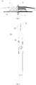
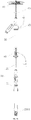
FIG. 1 is a schematic diagram of an occluder delivery system, in which a proximal end of a delivery sheath is connected to a distal end of a guide sheath after an occluder is received into the guide sheath by a preloader; -
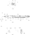
FIG. 2 is a structural schematic diagram of an occluder; -
FIG. 3 is a structural schematic diagram of an occluder pushing device; -
FIG. 4 is a schematic diagram of the internal structure of the pushing device shown inFIG. 3 ; -
FIG. 5a is an enlarged structural assembly schematic diagram showing the portion in circle A inFIG. 2 and the portion in circle B inFIG. 3 ; -
FIG. 5b is an enlarged structural diagram of the portion in circle C inFIG. 4 ; -
FIG. 6 is a top view of the internal structure of the pushing device shown inFIG. 4 ; -
FIG. 7 is a structural diagram of a locking component shown inFIG. 6 ; -
FIG. 8 is a sectional view of the locking component shown inFIG. 7 ; -
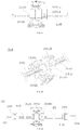
FIG. 9 is a structural diagram of a translation mechanism shown inFIG. 6 ; -
FIG. 10 is a bottom view of the translation mechanism shown inFIG. 9 ; -
FIG. 11 is a structural diagram of a horizontal driving component of the translation mechanism shown inFIG. 9 ; -
FIG. 12 is an exploded structural diagram of the horizontal driving component of the translation mechanism shown inFIG. 9 ; -
FIG. 13 is a connection schematic diagram of a traction element and a traction element mounting seat; -
FIG. 14 is a structural diagram of a second rotating element; -
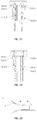
FIG. 15 is an axial sectional view of a rotation mechanism; -
FIG. 16 is a structural diagram of a base of the rotation mechanism; -
FIG. 17 is a structural diagram of an adjusting rod of the rotation mechanism; -
FIG. 18 is an end view, close to the second rotating element, of the adjusting rod shown inFIG. 17 ; -
FIG. 19 is an assembly schematic diagram of the second rotating element, the adjusting rod and the base; -
FIG. 20 is a sectional view taken along a section line I-I inFIG. 19 ; -
FIG. 21 is a state diagram showing the adjusting rod being axially rotatable relative to the base; -
FIG. 22 is a state diagram showing an adjusting rod being axially limited to the base; -
FIG. 23 is a structural schematic diagram of the preloader; -
FIG. 24 is a state diagram of the occluder during the operation of the pushing device; -
FIG. 25 is an enlarged structural view of the portion in circle D ofFIG. 24 ; -
FIG. 26 is another state diagram of the occluder during the operation of the pushing device (when the occluder is fully folded); -
FIG. 27 is a schematic diagram showing a pushing component being pulled to a proximal end to advance the occluder into the guide sheath through the preloader; and -
FIG. 28 is a schematic diagram of a pushing device pushing out the occluder through the delivery sheath after the occluder passes through a hemostatic valve and the guide sheath when the guide sheath is connected with the delivery sheath. - To facilitate an understanding of the present disclosure, the present disclosure will be described more fully hereinafter with reference to the accompanying drawings. Preferred implementations of the present disclosure are illustrated in the drawings. The present disclosure may, however, be embodied in many different forms and should not be construed as being limited to the implementations set forth herein. Rather, these implementations are provided so that the disclosure will be understood more thoroughly and completely.
- It should be noted that the terms "distal end" and "proximal end" are used as terms of orientation commonly used in the field of interventional medical devices, where the "distal end" refers to the end far away from an operator during the operation and the "proximal end" refers to the end close to the operator during the operation. The axial direction refers to a direction parallel to the line connecting the center of the distal end and the center of the proximal end of the medical device; and the radial direction refers to a direction perpendicular to the axial direction.
- Referring to
FIGs. 1-4 andFIG. 5a , an occluder delivery system includes a pushingdevice 20, adelivery sheath 60, and asheath core 70. The pushingdevice 20 includes a pushingcomponent 22 and ahandle 21. The pushingcomponent 22 includes a pushingtube 221 and atraction element 222 slidably inserted inside the pushingtube 221; and thehandle 21 is internally provided with a moving component and alocking component 214 which may lock thetraction element 222 and the pushingtube 221 in relative positions. The moving component includes atranslation mechanism 215 and arotation mechanism 216, wherein thetranslation mechanism 215 is configured to drive thetraction element 222 to move in an axial direction within the pushingtube 221; therotation mechanism 216 is configured to drive thetraction element 222 to rotate around an axis within the pushingtube 221; and therotation mechanism 216 includes a locking structure for locking or releasing the linkage between therotation mechanism 216 and thetraction element 222. Thus, it is possible to prevent the situation where therotation mechanism 216 drives the pullingelement 222 to rotate around the axis within the pushingtube 221 due to accidental touching of therotation mechanism 216 during the operation, thereby improving the operation accuracy of the pushingdevice 20. - Specifically, distal ends of the pushing
tube 221 and thetraction element 222 of the pushingcomponent 22 are detachably connected to a proximal end and a distal end of theoccluder 10, respectively, and thetranslation mechanism 215 enables the proximal end of theoccluder 10 to be close to, or far away from, the distal end of theoccluder 10 by controlling a relative position of thetraction element 222 in the pushingtube 221 so as to unfold or fold theoccluder 10. Thelocking component 214 locks thetraction element 222 in a relative position with respect to the pushingtube 221 to prevent accidental touching of the pushingdevice 20 causing thetraction element 222 to move along the pushingtube 221 to release theoccluder 10 in advance. - Of course, it should be understood that in some embodiments, the
delivery sheath 60 is a hollow tube and a bending direction of thedelivery sheath 60 is adjusted by thesheath core 70 connected to a proximal end of thedelivery sheath 60, so that the pushingtube 221 pushes theoccluder 10 along thedelivery sheath 60 to a defect to be occluded. - In some embodiments, the delivery system further includes a
hemostatic valve 50, wherein ahollow guide sheath 30 is detachably connected between thedelivery sheath 60 and thehemostatic valve 50, and an inner cavity of theguide sheath 30 is communicated with an inner cavity of thedelivery sheath 60 and an inner cavity of thehemostatic valve 50, such that theoccluder 10 is pushed by thedelivery sheath 60 after the foldedoccluder 10 is received into theguide sheath 30 in advance. - Referring also to
FIGs. 1 and24 , in some embodiments, apreloader 40 is detachably connected to a distal end of theguide sheath 30. Referring toFIG. 23 , thepreloader 40 includes ahorn section 41, aninterface section 43 and a connectingsection 42 connected between thehorn section 41 and theinterface section 43. Thehorn section 41 is formed with a large outwardly-extending opening to receive theoccluder 10 into theguide sheath 30 by pulling the pushingcomponent 22. It will be understood that the manner in which theinterface section 43 is detachably connected with theguide sheath 30 is through a threaded connection or a buckle connection, such that after theoccluder 10 is received in theguide sheath 30, thepreloader 40 is removed and the proximal end of thedelivery sheath 60 is connected to the distal end of theguide sheath 30. - Referring also to
FIGs. 2, 3 , and5a , in some embodiments, theoccluder 10 includes amesh disc 11, aflow blocking film 15, and asuturing part 16 for suturing themesh disc 11 to theflow blocking film 15. To enable the distal end and the proximal end of theoccluder 10 to be detachably connected with the distal ends of the pushingtube 221 and thetraction element 222, respectively, a distalend plug head 12 and aproximal end bolt 13 are arranged at the distal end and the proximal end, respectively, of theoccluder 10. The distalend plug head 12 is connected with anexternal thread 2221 of thetraction element 222 through a lockingelement 14 with aninternal thread 141, and theproximal end bolt 13 is provided with anexternal thread 131 that corresponds with theinternal thread 2211 provided at the distal end of the pushingtube 221. Further, the connection with theoccluder 10 may be removed or established by simply rotating the pushingtube 221 and thetraction element 222 when releasing or recovering theoccluder 10. Of course, it should be understood that, referring toFIG. 25 , theproximal end bolt 13 is provided with alocking hole 132 through which thelocking element 14 passes through and locks. Thetraction element 222 moves in the axial direction relative to the pushingtube 221 to enable the lockingelement 14 to drive the distalend plug head 12 to be close to or far away from theproximal end bolt 13 to unfold or fold theoccluder 10. - It should be understood that, in other embodiments, the
internal thread 141 may not be provided at the proximal end of the lockingelement 14, and the lockingelement 14 may be detachably connected with thetraction element 222 by a buckle. In other words, the connection between the lockingelement 14 and thetraction element 222 may be accomplished in other ways, which will not be specifically enumerated herein, so long as a detachable connection between the lockingelement 14 and thetraction element 222 is ensured. - Referring also to
FIGs. 4 and5b , in order to enable thetraction element 222 to move within the pushingtube 221, a proximal end of the pushingtube 221 is mounted to a housing of thehandle 21 through a fixingelement 213. In order to facilitate the assembly of internal members of thehandle 21, the housing of thehandle 21 is formed by enclosing acover 212 and abottom housing 211. A corresponding fixingelement 213 fixes the proximal end of the pushingtube 221 to thebottom housing 211 and enables thetraction element 222 to pass through the pushingtube 221, a proximal end of thetraction element 222 is connected to thetranslation mechanism 215, and thetraction element 222 moves within the pushingtube 221 as driven by thetranslation mechanism 215. It should be understood that the proximal end of thetraction element 222 passes through the proximal end of the pushingtube 221 to connect to thetranslation mechanism 215, and thelocking component 214 connected to thetraction element 222 can lock or release thetraction element 222, thereby locking the relative positions between thetraction element 222 and the pushingtube 221. - Referring also to
FIGs. 6-8 , in some embodiments, thelocking component 214 includes a fixingseat 2141, amovable element 2142, and an adjusting structure for adjusting apore 2145 between themovable element 2142 and the fixingseat 2141. It should be understood that the adjusting structure may lock or release thetraction element 222 by adjusting the size of thepore 2145 in such a manner that themovable element 2142 may clamp the fixingseat 2141 by pressing, or in such a manner that an annular element surrounding themovable element 2142 and the fixingseat 2141 may grip themovable element 2142 and the fixingseat 2141 when the annular element moves axially. The adjusting structure will be further described below with regard to how the gripping is accomplished. - Referring also to
FIGs. 7 and8 , in some embodiments, the adjusting structure includes asleeve 2143 surrounding the fixingseat 2141 and themovable element 2142, and alocking wheel 2144 that moves thesleeve 2143 axially relative to the fixingseat 2141 and themovable element 2142. - Specifically, the fixing
seat 2141 is fixed in thehandle 21 and thesleeve 2143 is connected with thelocking wheel 2144 by threads. Thus, the rotation of thelocking wheel 2144 may drive thesleeve 2143 to move axially to grip or release the fixingseat 2141 and themovable element 2142, thereby locking thetraction element 222, and further locking or releasing thetraction element 222 passing through thepore 2145 between themovable element 2142 and the fixingseat 2141. It should be understood that the diameter of the minimum inscribed circle of the projection of thesleeve 2143 on the cross section perpendicular to the axial direction is less than the diameter of the maximum circumscribed circle of the fixingseat 2141 and themovable element 2142; this ensures that a clamping force on thetraction element 222 may be created by the gripping of the fixingseat 2141 and themovable element 2142 when thesleeve 2143 is moved axially relative to the fixingseat 2141 and themovable element 2142. Of course, this axial relative movement requires defining the axial relative positions of thelocking wheel 2144 and the fixingseat 2141. Referring toFIG. 8 , a radially outwardly formedside edge 21411 of the fixingseat 2141 axially limits the fixingseat 2141 to thebottom housing 212 of thehandle 21. Similarly, thelocking wheel 2144 is also axially limited to thebottom housing 212 of thehandle 21, and to facilitate the operation of thelocking wheel 2144, ahub 21441 of thelocking wheel 2144 is at least partially exposed from thehandle 21. - Continuing to refer to
FIG. 8 , in some embodiments, a taperedblind hole 21431 is formed in thesleeve 2143; a circular truncated cone is formed by the alignment of themovable element 2142 and the fixingseat 2141, and the circular truncated cone is positioned in the taperedblind hole 21431; anend 21431b that is far away from theopening 21431a of the taperedblind hole 21431 of thesleeve 2143 is threadably connected with thelocking wheel 2144 through ascrew 21432. The clamping or loosening between the fixingseat 2141 and themovable element 2142 is achieved when the taperedblind hole 21431 is close to or far away from the circular truncated cone, respectively. Of course, in the present embodiment, the threaded transmission by means of thescrew 21432 is only to reduce the space occupied by the structure, and to facilitate the arrangement of thelocking wheel 2144 having a larger diameter to improve the torsion-resistant performance. It should be understood that thesleeve 2143 may also be axially driven by directly matching the internal thread of thelocking wheel 2144 with the external thread of the outer wall of thesleeve 2143. - Referring also to
FIGs. 6 and9 , in some embodiments, thetranslation mechanism 215 includes a firstrotating element 2151, a secondrotating element 2152, alinear guide rail 2153, abalance sliding rail 2155, and ahorizontal driving component 2154. The firstrotating element 2151 is axially provided with a throughhole 21541b through which thetraction element 222 extends. The secondrotating element 2152 is coaxial with the firstrotating element 2151; and thelinear guide rail 2153 and thebalance sliding rail 2155 are provided on the firstrotating element 2151 and the secondrotating element 2152, respectively, in a manner of being parallel to a rotation axis of the firstrotating element 2151. The proximal end of thetraction element 222 passes through the throughhole 21541b of the firstrotating element 2151 and is fixed to thehorizontal driving component 2154 so as to allow linear reciprocating motion along thelinear guide rail 2153 and thebalance sliding rail 2155 under the driving force of thehorizontal driving component 2154, and then axially moves relative to the pushingtube 221 fixed to thehandle 21 so as to fold or unfold theoccluder 10. - Referring also to
FIGs. 9 and13 , in some embodiments, thehorizontal driving component 2154 includes a tractionelement mounting seat 21541 and a pushingpart 21542 connected with the tractionelement mounting seat 21541. The tractionelement mounting seat 21541 is slidably provided on thelinear guide rail 2153 and thebalance sliding rail 2155, and the proximal end of thetraction element 222 is fixed to the tractionelement mounting seat 21541. The pushingpart 21542 is at least partially exposed from thehandle 21 so as to push the tractionelement mounting seat 21541 to move along thelinear guide rail 2153 and thebalance sliding rail 2155. It should be understood that thetraction element 222 may be fixed by alocking wire 21541d extending radially along the tractionelement mounting seat 21541, or may be fixed to the tractionelement mounting seat 21541 by other ways such as welding. - Referring to
FIG. 12 , in some embodiments, in order to prevent the tractionelement mounting seat 21541 from pushing too fast without being blocked while pushing thetraction element 222, dampingedges 21551 are provided on the surface of thebalance sliding rail 2155 along a moving direction of the tractionelement mounting seat 21541, and a slidingelement 21545 which elastically abuts against the dampingedges 21551 is provided in the tractionelement mounting seat 21541. Thus, when sliding axially, the tractionelement mounting seat 21541 will be blocked by the dampingedges 21551 on the surface of thebalance sliding rail 2155, so that theoccluder 10 may be slowly released during the operation, thereby reducing the adverse impacts caused by pushing too fast. - Specifically, in order to maintain the sliding
element 21545 in a state of elastically abutting against the dampingedges 21551, anelastic element 21544 may be provided at an end of the slidingelement 21545 far from the dampingedges 21551, so as to urge the slidingelement 21545 toward the damping edges 21551. It should be understood that a curved surface of the slidingelement 21545 is usually used to abut against the dampingedges 21551 so as to reduce wear during sliding, or to avoid inconvenience in pushing the tractionelement mounting seat 21541 caused by excessive blocking. - Referring also to
FIGs. 10 and11 , in the above-described embodiments, the tractionelement mounting seat 21541 is radially formed with the throughhole 21541b communicating with one sides of the dampingedges 21551 to provide a mounting space for theelastic element 21544 and the slidingelement 21545. Theelastic element 21544 is a spring, and the slidingelement 21545 is a ball. The bottom of the spring is pressed against the ball to enable the ball to abut against the dampingedges 21551, and the top of the spring is radially limited along the tractionelement mounting seat 21541 through afastening element 21543. It should be understood that thefastening element 21543 is a grub screw mounted on one side of the throughhole 21541b, and correspondingly, a threadedhole 21541a is formed in the tractionelement mounting seat 21541 to cooperate with the grub screw to fasten and press the spring downwardly. - In some embodiments, the pushing
part 21542 is axially limited on the tractionelement mounting seat 21541, and the firstrotating element 2151 and the secondrotating element 2152 drive the tractionelement mounting seat 21541 to rotate around the rotation axis of the firstrotating element 2151 relative to the pushingpart 21542 through thelinear guide rail 2153 and thebalance sliding rail 2155. The tractionelement mounting seat 21541 drives thetraction element 222 to rotate axially within the pushingtube 221, thereby connecting or separating the traction element with or from the lockingelement 14 of theoccluder 10. - In some embodiments, the traction
element mounting seat 21541 and the pushingpart 21542 are axially limited by a limitingedge 21541c and a limitinggroove 21542c, which are mutually aligned circumferentially, and the cross section of the limitingedge 21541c and the limitinggroove 21542c at the aligned position is circular to allow for the rotation of the tractionelement mounting seat 21541 relative to the pushingpart 21542. It should be understood that the limitingedge 21541c may be provided on the tractionelement mounting seat 21541 or on the pushingpart 21542. When the limitingedge 21541c is provided on the tractionelement mounting seat 21541, the pushingpart 21542 is provided with the limitinggroove 21542c aligned with the limitingedge 21541c; and when the limitingedge 21541c is provided on the pushingpart 21542, thetraction element 222 is provided with the limitinggroove 21542c aligned with the limitingedge 21541c. In the present embodiment, as shown inFIG. 12 , the tractionelement mounting seat 21541 and the pushingpart 21542 are each provided with the limitingedge 21541c and the limitinggroove 21542c which are aligned with each other, and it should be understood that the pushingpart 21542 includes a pushingpart seat 21542a and a pushing partupper cover 21542b to facilitate the assembly of the pushingpart 21542 on the tractionelement mounting seat 21541. - In some embodiments, to facilitate the rotation of the traction
element mounting seat 21541 relative to the pushingpart 21542, arotation mechanism 216 is provided at an end of the secondrotating element 2152 far from the firstrotating element 2151. Therotation mechanism 216 is rotated to drive the secondrotating element 2152 to rotate, thereby driving the tractionelement mounting seat 21541 to rotate axially through thelinear guide rail 2153 and thebalance sliding rail 2155. - Specifically, referring to
FIG. 15 , in some embodiments, therotation mechanism 216 includes abase 2161 and an adjustingrod 2162. Thebase 2161 is a hollow barrel and is fixed to the housing of thehandle 21; the adjustingrod 2162 is slidably inserted into thebase 2161 and rotatably linked with the secondrotating element 2152. Thus, the adjustingrod 2162 may rotate within thebase 2161 to rotate in linkage with the secondrotating element 2152. Referring also toFIGs. 14 and18-20 , it should be understood that the secondrotating element 2152 is inserted through a rotatingshaft control rod 2156 into aslot 21625 formed axially along the adjustingrod 2162, and the cross section perpendicular to the axis is non-circular, i.e., theslot 21625 allows the rotatingshaft control rod 2156 to move axially while limiting only the rotational degree of freedom of the rotatingshaft control rod 2156 to achieve rotational linkage around the axis. - In some embodiments, the locking structure is provided on the
base 2161 and the adjustingrod 2162. The locking structure has a locking state and an unlocking state in which the rotational degree of freedom of the adjustingrod 2162 within thebase 2161 is respectively restrained or released; and the locking structure may be in the locking state or the unlocking state by axially adjusting the relative positions of the adjustingrod 2162 and thebase 2161. Thus, rotation of the second rotatingmember 2152 due to accidentally touching of the adjustingrod 2162 during the pushing of theoccluder 10 is prevented. The distal end of thetraction element 222 fixedly connected to the tractionelement mounting seat 21541 is detached from the fastening element of theoccluder 10 by rotating the second rotatingmember 2152, and if the second rotatingmember 2152 is accidentally rotated, it would cause theoccluder 10 to be accidentally released. Therefore, if the rotation of the second rotatingmember 2152 is prevented, accidental release of theoccluder 10 can be prevented. - Referring also to
FIGs. 16-18 , in some embodiments, the locking structure includes stoppingpieces 21612, stoppingteeth 21621 and anannular groove 21611. The stoppingpieces 21612 are provided circumferentially at intervals around an inner side wall of thebase 2161; the stoppingteeth 21621 are provided circumferentially at intervals around an outer side wall of the adjustingrod 2162, andtooth grooves 21622 are formed between adjacent stoppingteeth 21621. Theannular groove 21611 is provided circumferentially around the inner side wall of thebase 2161. When the adjustingrod 2162 is rotated within thebase 2161, the stoppingteeth 21621 may rotate within theannular groove 21611. The stoppingpieces 21612 may be clamped in thetooth grooves 21622 or the stoppingteeth 21621 may be moved into theannular groove 21611 by axially adjusting the relative positions of the adjustingrod 2162 and thebase 2161 to limit or release the rotational degree of freedom between the adjustingrod 2162 and thebase 2161. It should be understood that when the rotational degree of freedom between the adjustingrod 2162 and thebase 2161 is limited, even if the adjustingrod 2162 is touched accidently, the adjustingrod 2162 will not rotate axially, thereby avoiding accidental touching of the pushingdevice 20 causing thetraction element 222 to rotate to be disconnected from theoccluder 10, and ensuring the accuracy of the release of theoccluder 10. - In some embodiments, position clamping structures are provided on the inner side wall of the
base 2161 and the outer side wall of the adjustingrod 2162, so that the adjustingrod 2162 may be axially limited in thebase 2161 without interference by external forces. Further, the adjustingrod 2162 and thebase 2161 are kept in a locked or released state of the rotational degree of freedom, so that accidental touching resulting in the adjustingrod 2162 being unlocked from the rotational degree of freedom of thebase 2161 is avoided. - Referring also to
FIGs. 15 ,17, and 19 , in some embodiments, therotation mechanism 216 further includes arotary cover 2164, aspring seat 2165, and aspring 2166 elastically pressed between thespring seat 2165 and therotary cover 2164. Therotary cover 2164 is fixed at an end of the adjustingrod 2162 far away from the secondrotating element 2152; and thespring seat 2165 surrounds thebase 2161. Therotary cover 2164 may be fixedly connected with the adjustingrod 2162 through a tighteningscrew 2163, and of course the fixing may also be accomplished through a buckle or the like. In this embodiment, as combined withFIG. 21 , the position clamping structure includes aclamping ring 21613 and afirst clamping groove 21623. Theclamping ring 21613 extends radially from the inner side wall of thebase 2161 and abuts against the outer side wall of the adjustingrod 2162; thefirst clamping groove 21623 is circumferentially formed around the outer side wall of the adjustingrod 2162; and when theclamping ring 21613 is received inside thefirst clamping groove 21623, the stoppingpieces 21612 are clamped in thetooth grooves 21622. Thus the adjustingrod 2162 is axially maintained with thebase 2161 in a state where the rotational degree of freedom is locked under the limitation of theclamping ring 21613 and thefirst clamping groove 21623, i.e., the adjustingrod 2162 cannot rotate relative to thebase 2161, so as to prevent thetraction element 222 from rotating due to accidental touching. When theclamping ring 21613 and thefirst clamping groove 21623 are disengaged, the stopping groove in the adjustingrod 2162 is driven away from the stoppingpieces 21612 and located in theannular groove 21611 under the elastic force of thespring 2166, so that by rotating therotary cover 2164 to rotate thetraction element 222, theoccluder 10 may be released through the disengagement from the connection, or may be recovered through the establishment of the connection. - Preferably, as combined with
FIG. 22 , the position clamping structure further includes asecond clamping groove 21624, wherein thesecond clamping groove 21624 is circumferentially formed around the outer side wall of the adjustingrod 2162; and when theclamping ring 21613 is received inside thesecond clamping groove 21624, the stoppingteeth 21621 are positioned in theannular groove 21611. The alignment of thesecond clamping groove 21624 and theclamping ring 21613 maintains the adjustingrod 2162 and thebase 2161 in the released state of the rotational degree of freedom, thereby avoiding the situation that the rotational degree of freedom of the adjustingrod 2162 is not sufficiently maintained in the released state when thespring 2166 fails, thereby improving the safety of operation, and ensuring that notraction element 222 will rotate and be disengaged from theoccluder 10 due to accidental touching of the pushingdevice 20. - Referring also to
FIGs. 24 and25 , when the pushingdevice 20 is used to deploy the occlude 10, the pushingcomponent 22 connected with thehandle 21 sequentially passes through thehemostatic valve 50, theguide sheath 30 and thepreloader 40, and the pushingtube 221 and thetraction element 222 of the pushingcomponent 22 are connected with theproximal end bolt 13 and the lockingelement 14 of theoccluder 10, respectively. Thus, thetraction element 222 may be controlled to move toward the distal end along the pushingtube 221 by pushing the pushingpart 21542 on thehandle 21 to move toward the distal end, leading the fastening element to drive the distalend plugging head 12 away from theproximal end bolt 13 to stretch and shape theoccluder 10 axially. With continued pushing on the pushingpart 21542 toward the distal end, theoccluder 10 is fully folded as shown inFIG. 26 , and thehub 21441 of thelocking wheel 2144 on thehandle 21 is rotated to lock the relative positions between thetraction element 222 and the pushingtube 221, so as to maintain theoccluder 10 in the folded state. Referring toFIG. 27 , pulling the pushingcomponent 22 toward the proximal end may move theoccluder 10 into theguide sheath 30 through thepreloader 40. Thepreloader 40 is removed from theguide sheath 30 and the distal end of theguide sheath 30 is connected with the proximal end of thedelivery sheath 60, so that the operation of loading theoccluder 10 into the occluder delivery system is completed. Referring toFIG. 28 , theoccluder 10 is pushed by the occluder delivery system through thedelivery sheath 60 to a pre-determined position where theoccluder 10 will be unfolded and released. It should be understood that since the movement of thetraction element 222 in thepush tube 221 is reversibly controlled by the pushingdevice 20, i.e., after unlocking thetraction element 222 from thelocking component 214, the pushingpart 21542 is pushed toward the proximal end to allow thetraction element 222 to drive the locking wire to be close to theproximal end bolt 13 connected with the distal end of the pushingtube 221, and then theoccluder 10 may be adjusted from the folded state to the unfolded state. In the process of adjusting the state of theoccluder 10 by the pushingdevice 20, when the tractionelement mounting seat 21541 slides axially, the tractionelement mounting seat 21541 will be blocked by the dampingedges 21551 on the surface of thebalance sliding rail 2155, so that theoccluder 10 may be slowly released during the operation, thereby reducing the adverse impacts caused by pushing too quickly. - The various technical features of the above-mentioned embodiments may be combined in any combination, and in order to simplify the description, not all possible combinations of the various technical features of the above-described embodiments are described, however, as long as there is no conflict between these technical features, they should be all considered to be the scope of disclosure contained in this description.
- The above embodiments are merely illustrative of several implementations of the present disclosure, which are described in more detail and are not to be construed as limiting the scope of the disclosure. It should be noted that several variations and modifications may be made by those skilled in the art without departing from the spirit of the disclosure, which all fall within the scope of the disclosure. Therefore, the protection scope of the disclosure shall be determined by the appended claims.
Claims (17)
- An occluder pushing device, comprising:a pushing component comprising a pushing tube and a traction element slidably inserted into the pushing tube; anda handle fixedly connected with a proximal end of the pushing tube and internally provided with a moving component and a locking component; wherein the moving component comprises a translation mechanism and a rotation mechanism; wherein the translation mechanism is configured to drive the traction element to move in an axial direction within the pushing tube; the rotation mechanism is configured to drive the traction element to rotate around an axis within the pushing tube;the locking component is configured to lock relative positions of the traction element and the pushing tube; andthe rotation mechanism comprises a locking structure for locking or releasing linkage between the rotation mechanism and the traction element.
- The occluder pushing device of claim 1, wherein the translation mechanism comprises:a first rotating element axially provided with a through hole through which the traction element extends;a second rotating element coaxial with the first rotating element;a linear guide rail and a balance sliding rail respectively provided on the first rotating element and the second rotating element and being parallel to a rotation axis of the first rotating element; anda horizontal driving component configured to drive a proximal end of the traction element to generate linear reciprocating motion along the linear guide rail and the balance sliding rail.
- The occluder pushing device of claim 2, wherein the horizontal driving component comprises:a traction element mounting seat slidably provided on the linear guide rail and the balance sliding rail, wherein the proximal end of the traction element is fixed to the traction element mounting seat; anda pushing part connected with the traction element mounting seat and at least partially exposed from the handle so as to push the traction element mounting seat to move along the linear guide rail and the balance sliding rail.
- The occluder pushing device of claim 2, wherein the rotation mechanism is provided at an end of the second rotating element far from the first rotating element, and the rotation mechanism further comprises:a base, which is a hollow barrel and is fixed to a housing of the handle; andan adjusting rod slidably inserted into the base and rotatably linked with the second rotating element, wherein the locking structure is provided on the base and the adjusting rod, and has a locked state and an unlocked state to respectively restrain and release the rotational degree of freedom of the adjusting rod within the base; andwherein the locking structure is capable of being placed in the locked state or the unlocked state by axially adjusting relative positions of the adjusting rod and the base.
- The occluder pushing device of claim 3, wherein a damping edge is provided on a surface of the balance sliding rail along a moving direction of the traction element mounting seat, and a sliding element which elastically abuts against the damping edge is provided in the traction element mounting seat.
- The occluder pushing device of claim 3, wherein the pushing part is axially limited on the traction element mounting seat, and the first rotating element and the second rotating element transmit the traction element mounting seat to rotate around the rotation axis of the first rotating element relative to the pushing part through the linear guide rail and the balance sliding rail.
- The occluder pushing device of claim 4, wherein the locking structure comprises:stopping pieces circumferentially provided at intervals around an inner side wall of the base;stopping teeth circumferentially provided at intervals around an outer side wall of the adjusting rod, wherein tooth grooves are formed between the adjacent stopping teeth; andan annular groove circumferentially formed around the inner side wall of the base, wherein when the adjusting rod rotates within the base, the stopping teeth rotate in the annular groove; andwherein the stopping pieces are capable of being clamped in the tooth grooves or the stopping teeth are capable of being moved into the annular groove by axially adjusting the relative positions of the adjusting rod and the base.
- The occluder pushing device of claim 6, wherein the traction element mounting seat and the pushing part are axially limited through a limiting edge and a limiting groove which are mutually aligned circumferentially, and the cross section of the limiting edge and the limiting groove at the matching position are circular to achieve the rotation of the traction element mounting seat relative to the pushing part.
- The occluder pushing device of claim 7, wherein position clamping structures are provided on the inner side wall of the base and the outer side wall of the adjusting rod, so that the adjusting rod is axially limited in the base without interference of external force.
- The occluder pushing device of claim 9, wherein the rotation mechanism further comprises:a rotary cover fixed at an end of the adjusting rod far from the second rotating element;a spring seat surrounding the base; anda spring elastically pressed between the spring seat and the rotary cover; andwherein the position clamping structure comprises a clamping ring and a first clamping groove, wherein the clamping ring extends radially from the inner side wall of the base and abuts against the outer side wall of the adjusting rod; the first clamping groove is circumferentially formed around the outer side wall of the adjusting rod; andwhen the clamping ring is buckled with the first clamping groove, the stopping pieces are clamped in the tooth grooves.
- The occluder pushing device of claim 10, wherein the position clamping structure further comprises a second clamping groove, wherein the second clamping groove is circumferentially formed around the outer side wall of the adjusting rod; and
when the clamping ring is buckled with the second clamping groove, the stopping teeth are positioned in the annular groove. - The occluder pushing device of any one of claims 1 to 11, wherein the locking component comprises:a fixing seat fixed in the handle;a movable element, a pore is formed between the movable element and the fixing seat for the traction element to pass through; andan adjusting structure configured to adjust the pore between the movable element and the fixing seat so as to lock or release the traction element.
- The occluder pushing device of claim 12, wherein the adjusting structure comprises:a sleeve surrounding the fixing seat and the movable element, wherein the diameter of the minimum inscribed circle of the projection of the sleeve on the cross section perpendicular to the axial direction is less than the diameter of the maximum circumscribed circle of the fixing seat and the movable element; anda locking wheel axially limited in the handle and in threaded connection with the sleeve, wherein a hub of the locking wheel is at least partially exposed from the handle to rotate the locking wheel to transmit the sleeve to move axially, so that the sleeve grips or releases the fixing seat and the movable element.
- The occluder pushing device of claim 13, wherein a tapered blind hole is formed in the sleeve; a circular truncated cone is formed by the alignment of the movable element and the fixing seat, and positioned in the tapered blind hole; and an end of the sleeve far from the opening of the tapered blind hole is in threaded connection with the locking wheel through a screw.
- An occluder delivery system, comprising the pushing device of any one of claims 1 to 14, and
a delivery sheath, which is a hollow tube, and the pushing tube of the pushing device is slidably inserted into the delivery sheath; and
a sheath core connected to a proximal end of the delivery sheath and configured to adjust a bending direction of the delivery sheath so that the pushing tube pushes the occluder to a defect to be occluded along the delivery sheath. - The occluder delivery system of claim 15, wherein the delivery system further comprises a hemostatic valve, wherein a hollow guide sheath is detachably connected between the delivery sheath and the hemostatic valve, and an inner cavity of the guide sheath is communicated with an inner cavity of the delivery sheath and an inner cavity of the hemostatic valve.
- The occluder delivery system of claim 16, wherein the delivery system further comprises a preloader detachably connected to a distal end of the guide sheath, and the preloader comprises a horn section and an interface section, and a connecting section connected between the horn section and the interface section.
Applications Claiming Priority (2)
| Application Number | Priority Date | Filing Date | Title |
|---|---|---|---|
| CN201710572190.8A CN109247959B (en) | 2017-07-13 | 2017-07-13 | Plugging device pushing device and conveying system |
| PCT/CN2018/094995 WO2019011214A1 (en) | 2017-07-13 | 2018-07-09 | Occluder pushing device and transport system |
Publications (3)
| Publication Number | Publication Date |
|---|---|
| EP3653133A1 true EP3653133A1 (en) | 2020-05-20 |
| EP3653133A4 EP3653133A4 (en) | 2021-04-14 |
| EP3653133B1 EP3653133B1 (en) | 2024-02-21 |
Family
ID=65001097
Family Applications (1)
| Application Number | Title | Priority Date | Filing Date |
|---|---|---|---|
| EP18832502.1A Active EP3653133B1 (en) | 2017-07-13 | 2018-07-09 | Occluder pushing device and transport system |
Country Status (5)
| Country | Link |
|---|---|
| US (1) | US11419591B2 (en) |
| EP (1) | EP3653133B1 (en) |
| CN (2) | CN109247959B (en) |
| ES (1) | ES2975932T3 (en) |
| WO (1) | WO2019011214A1 (en) |
Families Citing this family (39)
| Publication number | Priority date | Publication date | Assignee | Title |
|---|---|---|---|---|
| US11399842B2 (en) | 2013-03-13 | 2022-08-02 | Conformal Medical, Inc. | Devices and methods for excluding the left atrial appendage |
| EP2968878B1 (en) | 2013-03-13 | 2020-08-12 | Conformal Medical, Inc. | Devices for excluding the left atrial appendage |
| WO2018081466A2 (en) | 2016-10-27 | 2018-05-03 | Conformal Medical, Inc. | Devices and methods for excluding the left atrial appendage |
| US11426172B2 (en) | 2016-10-27 | 2022-08-30 | Conformal Medical, Inc. | Devices and methods for excluding the left atrial appendage |
| CN109247959B (en) * | 2017-07-13 | 2020-07-03 | 先健科技(深圳)有限公司 | Plugging device pushing device and conveying system |
| US12268394B2 (en) | 2019-02-08 | 2025-04-08 | Conformal Medical, Inc. | Devices and methods for excluding the left atrial appendage |
| US12144508B2 (en) | 2019-02-08 | 2024-11-19 | Conformal Medical, Inc. | Devices and methods for excluding the left atrial appendage |
| WO2020207485A1 (en) * | 2019-04-11 | 2020-10-15 | 杭州唯强医疗科技有限公司 | Occluder and locking system of occluder |
| CN111803166B (en) * | 2019-04-11 | 2025-09-12 | 杭州唯强医疗科技有限公司 | Occluder and occluder locking system |
| WO2020207484A1 (en) * | 2019-04-11 | 2020-10-15 | 杭州唯强医疗科技有限公司 | Occluder, occluder fastening system and fastening method |
| CN111803168B (en) * | 2019-04-11 | 2024-11-29 | 杭州唯强医疗科技有限公司 | Interventional medical instrument pushing device |
| CN110559022B (en) * | 2019-04-30 | 2023-11-24 | 上海科赐医疗技术有限公司 | Medical asymmetric balloon catheter with manipulator |
| US11701491B2 (en) * | 2019-08-27 | 2023-07-18 | St. Jude Medical, Cardiology Division, Inc. | Deflectable torque cable for delivery of medical devices |
| CN110876633B (en) * | 2019-12-03 | 2024-06-14 | 江苏博朗森思医疗器械有限公司 | Special conveyer of degradable plugging device |
| US11992221B2 (en) | 2019-12-20 | 2024-05-28 | Lifetech Scientific (Shenzhen) Co., Ltd. | Occluder, occluding system and conveying device |
| CN112998796B (en) * | 2019-12-20 | 2023-01-03 | 先健科技(深圳)有限公司 | Conveying device |
| US11992643B2 (en) * | 2019-12-20 | 2024-05-28 | Neuravi Limited | Neurovascular insertion tool |
| CN111067667B (en) * | 2019-12-27 | 2022-04-22 | 先健科技(深圳)有限公司 | Force measuring device and pushing assembly thereof |
| US12376840B2 (en) * | 2020-01-07 | 2025-08-05 | Lifetech Scientific (Shenzhen) Co., Ltd. | Occluder pushing device and transport system |
| EP4110419B1 (en) * | 2020-02-26 | 2025-07-23 | Boston Scientific Scimed, Inc. | Endoluminal seal and methods of use |
| CN111728738B (en) * | 2020-07-17 | 2025-07-08 | 上海翰凌医疗器械有限公司 | Driving device |
| CN112353537B (en) * | 2020-11-02 | 2025-08-12 | 北京燕康科技有限公司 | Conveying system with locking mechanism |
| CN112401947B (en) * | 2020-11-24 | 2023-08-08 | 李建朝 | Spherical structure plugging device for extracardiac operation and application method thereof |
| CN114587439B (en) * | 2020-12-07 | 2024-02-20 | 先健科技(深圳)有限公司 | Conveyors and conveying systems |
| CN114642466B (en) * | 2020-12-17 | 2024-04-02 | 先健科技(深圳)有限公司 | Conveying device and conveying system |
| CN113124039A (en) * | 2021-06-01 | 2021-07-16 | 法罗适(上海)医疗技术有限公司 | Plug-in quick switching interface for replacing wire drive rehabilitation gloves |
| CN115500875B (en) * | 2021-06-23 | 2025-03-07 | 北京迈迪顶峰医疗科技股份有限公司 | A delivery handle and delivery system for a left atrial appendage occluder |
| CN113951950B (en) * | 2021-09-29 | 2023-10-27 | 上海电气集团股份有限公司 | Connecting device and traction bed |
| CN114041835B (en) * | 2021-11-19 | 2024-04-09 | 中国医学科学院北京协和医院 | A retrievable occluder for treating congenital heart disease |
| CN114305818B (en) * | 2021-12-01 | 2025-08-05 | 宁波迪创医疗科技有限公司 | Implantable device and its assembly and removal tool assembly |
| WO2023116369A1 (en) * | 2021-12-24 | 2023-06-29 | 上海微创心通医疗科技有限公司 | Delivery system and control handle thereof |
| CN114010244B (en) * | 2022-01-06 | 2022-04-12 | 深圳佰特微医疗科技有限公司 | tissue traction device |
| CN115106663B (en) * | 2022-08-10 | 2025-10-28 | 湖南大学 | Multi-ray coaxial laser processing monitoring device based on active illumination |
| CN115969452B (en) * | 2023-03-21 | 2023-07-18 | 北京普益盛济科技有限公司 | Lumen access closure and lumen access closure delivery system |
| US12178420B1 (en) * | 2023-10-19 | 2024-12-31 | Atheart Medical Ag | Systems and methods for delivering implantable occluder devices for treating atrial septal defects |
| AU2024363701A1 (en) * | 2023-10-19 | 2026-04-16 | Atheart Medical Ag | Systems and methods for delivering implantable occluder devices for treating atrial septal defects |
| CN118614970A (en) * | 2024-06-20 | 2024-09-10 | 北京审谛医疗科技有限公司 | A device for treating ventricular septal defect |
| CN119607370B (en) * | 2024-12-10 | 2026-03-17 | 四川普瑞顺祥医疗器械有限公司 | A negative pressure suction ureteral guide sheath |
| CN119606448B (en) * | 2024-12-18 | 2025-12-02 | 先健科技(深圳)有限公司 | A pusher and system for a plugging device |
Family Cites Families (34)
| Publication number | Priority date | Publication date | Assignee | Title |
|---|---|---|---|---|
| US4258722A (en) * | 1978-12-15 | 1981-03-31 | Ferris Manufacturing Corp. | Disposable biopsy needle, particularly for bone marrow samplings |
| US5707376A (en) * | 1992-08-06 | 1998-01-13 | William Cook Europe A/S | Stent introducer and method of use |
| US6132390A (en) * | 1996-02-28 | 2000-10-17 | Eupalamus Llc | Handle for manipulation of a stylet used for deflecting a tip of a lead or catheter |
| US6623518B2 (en) * | 2001-02-26 | 2003-09-23 | Ev3 Peripheral, Inc. | Implant delivery system with interlock |
| JP4328209B2 (en) * | 2002-01-25 | 2009-09-09 | アトリテック, インコーポレイテッド | Atrial appendage blood filtration system |
| US8398656B2 (en) * | 2003-01-30 | 2013-03-19 | Integrated Vascular Systems, Inc. | Clip applier and methods of use |
| US7278970B2 (en) * | 2003-07-29 | 2007-10-09 | Goldenberg Alec S | Biopsy needles |
| CN101926667B (en) * | 2005-05-25 | 2012-12-05 | 泰科保健集团有限合伙公司 | System and method for conveying and unfolding stopper in blood vessel |
| US7938851B2 (en) * | 2005-06-08 | 2011-05-10 | Xtent, Inc. | Devices and methods for operating and controlling interventional apparatus |
| JP5220101B2 (en) * | 2007-05-15 | 2013-06-26 | イエナバルブ テクノロジー インク | Handle for manipulating the catheter tip, catheter system and medical insertion system to insert a self-expanding heart valve stent |
| US8034061B2 (en) * | 2007-07-12 | 2011-10-11 | Aga Medical Corporation | Percutaneous catheter directed intravascular occlusion devices |
| CN101496730A (en) * | 2008-02-02 | 2009-08-05 | 先健科技(深圳)有限公司 | Flexible releasing conveying system |
| US7942886B2 (en) * | 2008-06-25 | 2011-05-17 | Alfredo Alvarado | Transabdominal needle introducer |
| US10219796B2 (en) * | 2009-02-21 | 2019-03-05 | Farideh Roshanali | Device for percutaneous transcathertral closure of atrial septal defect by deploying pericardial patch |
| US10064628B2 (en) | 2009-06-17 | 2018-09-04 | Coherex Medical, Inc. | Medical device for modification of left atrial appendage and related systems and methods |
| US10201336B2 (en) * | 2011-03-25 | 2019-02-12 | St. Jude Medical, Cardiology Division, Inc. | Device and method for delivering a vascular device |
| CN103655004B (en) * | 2012-09-21 | 2015-11-25 | 上海微创医疗器械(集团)有限公司 | Implant delivery system |
| US10993741B2 (en) * | 2013-03-15 | 2021-05-04 | Spectranetics Llc | Surgical cutting device with shield drive mechanism |
| EP3003185B1 (en) * | 2013-05-29 | 2018-05-23 | Spinal Simplicity LLC | Instrument for inserting an interspinous process implant |
| CN203388893U (en) * | 2013-07-12 | 2014-01-15 | 上海形状记忆合金材料有限公司 | Heart defect sealing and plugging device conveying system |
| CN203943701U (en) * | 2014-07-07 | 2014-11-19 | 宁波健世生物科技有限公司 | A kind of novel dismountable induction system |
| US9737688B2 (en) * | 2014-09-12 | 2017-08-22 | Freudenberg Medical, Llc | Modular handle assembly for a steerable catheter |
| CN104586440B (en) * | 2014-12-31 | 2017-12-26 | 上海形状记忆合金材料有限公司 | A kind of heart defect amplatzer induction system |
| CN204798072U (en) * | 2015-07-01 | 2015-11-25 | 微创心脉医疗科技(上海)有限公司 | A pipe handle for implant conveying system |
| US10575951B2 (en) * | 2015-08-26 | 2020-03-03 | Edwards Lifesciences Cardiaq Llc | Delivery device and methods of use for transapical delivery of replacement mitral valve |
| EP3351187B1 (en) * | 2015-09-17 | 2020-05-06 | Olympus Corporation | Endoscope treatment instrument |
| US10238495B2 (en) * | 2015-10-09 | 2019-03-26 | Evalve, Inc. | Delivery catheter handle and methods of use |
| CN105943212B (en) * | 2015-12-23 | 2018-08-14 | 微创心脉医疗科技(上海)有限公司 | Stent delivery system and its Handleset |
| CN205729432U (en) * | 2015-12-30 | 2016-11-30 | 先健科技(深圳)有限公司 | Pusher and induction system |
| CN113017767A (en) * | 2016-06-08 | 2021-06-25 | 深圳市科奕顿生物医疗科技有限公司 | Interventional medical instrument conveying system and method |
| CN110730628B (en) * | 2017-03-30 | 2022-05-13 | 纽维拉医疗公司 | Medical tool positioning device, system and methods of use and manufacture |
| EP3624739A1 (en) * | 2017-05-15 | 2020-03-25 | St. Jude Medical, Cardiology Division, Inc. | Transcatheter delivery system with wheel actuation |
| CN109247959B (en) * | 2017-07-13 | 2020-07-03 | 先健科技(深圳)有限公司 | Plugging device pushing device and conveying system |
| CN208541339U (en) * | 2017-07-13 | 2019-02-26 | 先健科技(深圳)有限公司 | Occluder push device and delivery system |
-
2017
- 2017-07-13 CN CN201710572190.8A patent/CN109247959B/en active Active
- 2017-07-13 CN CN202010268063.0A patent/CN111419299B/en active Active
-
2018
- 2018-07-09 ES ES18832502T patent/ES2975932T3/en active Active
- 2018-07-09 EP EP18832502.1A patent/EP3653133B1/en active Active
- 2018-07-09 US US16/629,112 patent/US11419591B2/en active Active
- 2018-07-09 WO PCT/CN2018/094995 patent/WO2019011214A1/en not_active Ceased
Also Published As
| Publication number | Publication date |
|---|---|
| CN109247959A (en) | 2019-01-22 |
| CN111419299A (en) | 2020-07-17 |
| WO2019011214A1 (en) | 2019-01-17 |
| US20200222034A1 (en) | 2020-07-16 |
| CN109247959B (en) | 2020-07-03 |
| US11419591B2 (en) | 2022-08-23 |
| ES2975932T3 (en) | 2024-07-18 |
| EP3653133A4 (en) | 2021-04-14 |
| EP3653133B1 (en) | 2024-02-21 |
| CN111419299B (en) | 2021-08-31 |
Similar Documents
| Publication | Publication Date | Title |
|---|---|---|
| US11419591B2 (en) | Occluder pushing device and transport system | |
| US12376840B2 (en) | Occluder pushing device and transport system | |
| EP3165174B1 (en) | Occluder and occlusion device | |
| US9101340B2 (en) | Insertion tool for a closure device | |
| US7955354B2 (en) | Occlusion device and surgical instrument and method for its implantation/explantation | |
| EP0856285B1 (en) | Device for intracardiac suture | |
| CN111803166B (en) | Occluder and occluder locking system | |
| CN110537946A (en) | tissue clamping device and using method thereof | |
| CN110313951B (en) | Suture shackle and suture locking system | |
| CN114343767B (en) | Occluder delivery device and intracavitary rupture occlusion system | |
| CA2816906A1 (en) | Device and method for delivering a vascular device | |
| US11844529B2 (en) | Hemostatic clip | |
| US11141165B2 (en) | Hemostatic clamp | |
| CN114469226B (en) | Sheath tube bending-adjustable device and intracavity fracture plugging system | |
| CN210408509U (en) | Occluder and occluder locking system | |
| US20220022856A1 (en) | Occluder and occluder fastening system | |
| CN114376629B (en) | Occluder and occluder locking system | |
| CN208541339U (en) | Occluder push device and delivery system | |
| CN117398140A (en) | Cardiac suturing device with limiting piece | |
| CN214595939U (en) | Hemostatic clamp | |
| CN117982180A (en) | Occluder and occluder locking system | |
| CN219895806U (en) | Conveying handle | |
| CN211934177U (en) | Conveyor and interventional system | |
| CN120168019A (en) | A wire taking-up mechanism for a conveying device, a conveying device and a conveying system | |
| WO2025208688A1 (en) | One-handed rotary wheel-type self-locking grasping forceps |
Legal Events
| Date | Code | Title | Description |
|---|---|---|---|
| STAA | Information on the status of an ep patent application or granted ep patent |
Free format text: STATUS: THE INTERNATIONAL PUBLICATION HAS BEEN MADE |
|
| PUAI | Public reference made under article 153(3) epc to a published international application that has entered the european phase |
Free format text: ORIGINAL CODE: 0009012 |
|
| STAA | Information on the status of an ep patent application or granted ep patent |
Free format text: STATUS: REQUEST FOR EXAMINATION WAS MADE |
|
| 17P | Request for examination filed |
Effective date: 20200212 |
|
| AK | Designated contracting states |
Kind code of ref document: A1 Designated state(s): AL AT BE BG CH CY CZ DE DK EE ES FI FR GB GR HR HU IE IS IT LI LT LU LV MC MK MT NL NO PL PT RO RS SE SI SK SM TR |
|
| AX | Request for extension of the european patent |
Extension state: BA ME |
|
| DAV | Request for validation of the european patent (deleted) | ||
| DAX | Request for extension of the european patent (deleted) | ||
| A4 | Supplementary search report drawn up and despatched |
Effective date: 20210312 |
|
| RIC1 | Information provided on ipc code assigned before grant |
Ipc: A61B 17/00 20060101AFI20210308BHEP Ipc: A61B 17/12 20060101ALI20210308BHEP |
|
| RIC1 | Information provided on ipc code assigned before grant |
Ipc: A61B 17/12 20060101ALI20230713BHEP Ipc: A61B 17/00 20060101AFI20230713BHEP |
|
| GRAP | Despatch of communication of intention to grant a patent |
Free format text: ORIGINAL CODE: EPIDOSNIGR1 |
|
| STAA | Information on the status of an ep patent application or granted ep patent |
Free format text: STATUS: GRANT OF PATENT IS INTENDED |
|
| INTG | Intention to grant announced |
Effective date: 20230919 |
|
| RAP3 | Party data changed (applicant data changed or rights of an application transferred) |
Owner name: LIFETECH SCIENTIFIC (SHENZHEN) CO. LTD. |
|
| GRAS | Grant fee paid |
Free format text: ORIGINAL CODE: EPIDOSNIGR3 |
|
| GRAA | (expected) grant |
Free format text: ORIGINAL CODE: 0009210 |
|
| STAA | Information on the status of an ep patent application or granted ep patent |
Free format text: STATUS: THE PATENT HAS BEEN GRANTED |
|
| AK | Designated contracting states |
Kind code of ref document: B1 Designated state(s): AL AT BE BG CH CY CZ DE DK EE ES FI FR GB GR HR HU IE IS IT LI LT LU LV MC MK MT NL NO PL PT RO RS SE SI SK SM TR |
|
| P01 | Opt-out of the competence of the unified patent court (upc) registered |
Effective date: 20240117 |
|
| REG | Reference to a national code |
Ref country code: GB Ref legal event code: FG4D |
|
| REG | Reference to a national code |
Ref country code: CH Ref legal event code: EP |
|
| REG | Reference to a national code |
Ref country code: DE Ref legal event code: R096 Ref document number: 602018065623 Country of ref document: DE |
|
| REG | Reference to a national code |
Ref country code: IE Ref legal event code: FG4D |
|
| REG | Reference to a national code |
Ref country code: LT Ref legal event code: MG9D |
|
| REG | Reference to a national code |
Ref country code: NL Ref legal event code: MP Effective date: 20240221 |
|
| PG25 | Lapsed in a contracting state [announced via postgrant information from national office to epo] |
Ref country code: IS Free format text: LAPSE BECAUSE OF FAILURE TO SUBMIT A TRANSLATION OF THE DESCRIPTION OR TO PAY THE FEE WITHIN THE PRESCRIBED TIME-LIMIT Effective date: 20240621 |
|
| PG25 | Lapsed in a contracting state [announced via postgrant information from national office to epo] |
Ref country code: LT Free format text: LAPSE BECAUSE OF FAILURE TO SUBMIT A TRANSLATION OF THE DESCRIPTION OR TO PAY THE FEE WITHIN THE PRESCRIBED TIME-LIMIT Effective date: 20240221 |
|
| PG25 | Lapsed in a contracting state [announced via postgrant information from national office to epo] |
Ref country code: GR Free format text: LAPSE BECAUSE OF FAILURE TO SUBMIT A TRANSLATION OF THE DESCRIPTION OR TO PAY THE FEE WITHIN THE PRESCRIBED TIME-LIMIT Effective date: 20240522 |
|
| REG | Reference to a national code |
Ref country code: AT Ref legal event code: MK05 Ref document number: 1658370 Country of ref document: AT Kind code of ref document: T Effective date: 20240221 |
|
| PG25 | Lapsed in a contracting state [announced via postgrant information from national office to epo] |
Ref country code: RS Free format text: LAPSE BECAUSE OF FAILURE TO SUBMIT A TRANSLATION OF THE DESCRIPTION OR TO PAY THE FEE WITHIN THE PRESCRIBED TIME-LIMIT Effective date: 20240521 Ref country code: NL Free format text: LAPSE BECAUSE OF FAILURE TO SUBMIT A TRANSLATION OF THE DESCRIPTION OR TO PAY THE FEE WITHIN THE PRESCRIBED TIME-LIMIT Effective date: 20240221 Ref country code: HR Free format text: LAPSE BECAUSE OF FAILURE TO SUBMIT A TRANSLATION OF THE DESCRIPTION OR TO PAY THE FEE WITHIN THE PRESCRIBED TIME-LIMIT Effective date: 20240221 |
|
| REG | Reference to a national code |
Ref country code: ES Ref legal event code: FG2A Ref document number: 2975932 Country of ref document: ES Kind code of ref document: T3 Effective date: 20240718 |
|
| PG25 | Lapsed in a contracting state [announced via postgrant information from national office to epo] |
Ref country code: AT Free format text: LAPSE BECAUSE OF FAILURE TO SUBMIT A TRANSLATION OF THE DESCRIPTION OR TO PAY THE FEE WITHIN THE PRESCRIBED TIME-LIMIT Effective date: 20240221 |
|
| PG25 | Lapsed in a contracting state [announced via postgrant information from national office to epo] |
Ref country code: RS Free format text: LAPSE BECAUSE OF FAILURE TO SUBMIT A TRANSLATION OF THE DESCRIPTION OR TO PAY THE FEE WITHIN THE PRESCRIBED TIME-LIMIT Effective date: 20240521 Ref country code: NO Free format text: LAPSE BECAUSE OF FAILURE TO SUBMIT A TRANSLATION OF THE DESCRIPTION OR TO PAY THE FEE WITHIN THE PRESCRIBED TIME-LIMIT Effective date: 20240521 Ref country code: NL Free format text: LAPSE BECAUSE OF FAILURE TO SUBMIT A TRANSLATION OF THE DESCRIPTION OR TO PAY THE FEE WITHIN THE PRESCRIBED TIME-LIMIT Effective date: 20240221 Ref country code: LT Free format text: LAPSE BECAUSE OF FAILURE TO SUBMIT A TRANSLATION OF THE DESCRIPTION OR TO PAY THE FEE WITHIN THE PRESCRIBED TIME-LIMIT Effective date: 20240221 Ref country code: IS Free format text: LAPSE BECAUSE OF FAILURE TO SUBMIT A TRANSLATION OF THE DESCRIPTION OR TO PAY THE FEE WITHIN THE PRESCRIBED TIME-LIMIT Effective date: 20240621 Ref country code: HR Free format text: LAPSE BECAUSE OF FAILURE TO SUBMIT A TRANSLATION OF THE DESCRIPTION OR TO PAY THE FEE WITHIN THE PRESCRIBED TIME-LIMIT Effective date: 20240221 Ref country code: GR Free format text: LAPSE BECAUSE OF FAILURE TO SUBMIT A TRANSLATION OF THE DESCRIPTION OR TO PAY THE FEE WITHIN THE PRESCRIBED TIME-LIMIT Effective date: 20240522 Ref country code: FI Free format text: LAPSE BECAUSE OF FAILURE TO SUBMIT A TRANSLATION OF THE DESCRIPTION OR TO PAY THE FEE WITHIN THE PRESCRIBED TIME-LIMIT Effective date: 20240221 Ref country code: BG Free format text: LAPSE BECAUSE OF FAILURE TO SUBMIT A TRANSLATION OF THE DESCRIPTION OR TO PAY THE FEE WITHIN THE PRESCRIBED TIME-LIMIT Effective date: 20240221 Ref country code: AT Free format text: LAPSE BECAUSE OF FAILURE TO SUBMIT A TRANSLATION OF THE DESCRIPTION OR TO PAY THE FEE WITHIN THE PRESCRIBED TIME-LIMIT Effective date: 20240221 |
|
| PG25 | Lapsed in a contracting state [announced via postgrant information from national office to epo] |
Ref country code: PL Free format text: LAPSE BECAUSE OF FAILURE TO SUBMIT A TRANSLATION OF THE DESCRIPTION OR TO PAY THE FEE WITHIN THE PRESCRIBED TIME-LIMIT Effective date: 20240221 Ref country code: PT Free format text: LAPSE BECAUSE OF FAILURE TO SUBMIT A TRANSLATION OF THE DESCRIPTION OR TO PAY THE FEE WITHIN THE PRESCRIBED TIME-LIMIT Effective date: 20240621 |
|
| PG25 | Lapsed in a contracting state [announced via postgrant information from national office to epo] |
Ref country code: SE Free format text: LAPSE BECAUSE OF FAILURE TO SUBMIT A TRANSLATION OF THE DESCRIPTION OR TO PAY THE FEE WITHIN THE PRESCRIBED TIME-LIMIT Effective date: 20240221 Ref country code: PT Free format text: LAPSE BECAUSE OF FAILURE TO SUBMIT A TRANSLATION OF THE DESCRIPTION OR TO PAY THE FEE WITHIN THE PRESCRIBED TIME-LIMIT Effective date: 20240621 Ref country code: PL Free format text: LAPSE BECAUSE OF FAILURE TO SUBMIT A TRANSLATION OF THE DESCRIPTION OR TO PAY THE FEE WITHIN THE PRESCRIBED TIME-LIMIT Effective date: 20240221 Ref country code: LV Free format text: LAPSE BECAUSE OF FAILURE TO SUBMIT A TRANSLATION OF THE DESCRIPTION OR TO PAY THE FEE WITHIN THE PRESCRIBED TIME-LIMIT Effective date: 20240221 |
|
| PG25 | Lapsed in a contracting state [announced via postgrant information from national office to epo] |
Ref country code: DK Free format text: LAPSE BECAUSE OF FAILURE TO SUBMIT A TRANSLATION OF THE DESCRIPTION OR TO PAY THE FEE WITHIN THE PRESCRIBED TIME-LIMIT Effective date: 20240221 |
|
| PG25 | Lapsed in a contracting state [announced via postgrant information from national office to epo] |
Ref country code: SM Free format text: LAPSE BECAUSE OF FAILURE TO SUBMIT A TRANSLATION OF THE DESCRIPTION OR TO PAY THE FEE WITHIN THE PRESCRIBED TIME-LIMIT Effective date: 20240221 |
|
| PG25 | Lapsed in a contracting state [announced via postgrant information from national office to epo] |
Ref country code: EE Free format text: LAPSE BECAUSE OF FAILURE TO SUBMIT A TRANSLATION OF THE DESCRIPTION OR TO PAY THE FEE WITHIN THE PRESCRIBED TIME-LIMIT Effective date: 20240221 Ref country code: CZ Free format text: LAPSE BECAUSE OF FAILURE TO SUBMIT A TRANSLATION OF THE DESCRIPTION OR TO PAY THE FEE WITHIN THE PRESCRIBED TIME-LIMIT Effective date: 20240221 |
|
| PG25 | Lapsed in a contracting state [announced via postgrant information from national office to epo] |
Ref country code: SK Free format text: LAPSE BECAUSE OF FAILURE TO SUBMIT A TRANSLATION OF THE DESCRIPTION OR TO PAY THE FEE WITHIN THE PRESCRIBED TIME-LIMIT Effective date: 20240221 |
|
| PG25 | Lapsed in a contracting state [announced via postgrant information from national office to epo] |
Ref country code: SM Free format text: LAPSE BECAUSE OF FAILURE TO SUBMIT A TRANSLATION OF THE DESCRIPTION OR TO PAY THE FEE WITHIN THE PRESCRIBED TIME-LIMIT Effective date: 20240221 Ref country code: SK Free format text: LAPSE BECAUSE OF FAILURE TO SUBMIT A TRANSLATION OF THE DESCRIPTION OR TO PAY THE FEE WITHIN THE PRESCRIBED TIME-LIMIT Effective date: 20240221 Ref country code: RO Free format text: LAPSE BECAUSE OF FAILURE TO SUBMIT A TRANSLATION OF THE DESCRIPTION OR TO PAY THE FEE WITHIN THE PRESCRIBED TIME-LIMIT Effective date: 20240221 Ref country code: EE Free format text: LAPSE BECAUSE OF FAILURE TO SUBMIT A TRANSLATION OF THE DESCRIPTION OR TO PAY THE FEE WITHIN THE PRESCRIBED TIME-LIMIT Effective date: 20240221 Ref country code: DK Free format text: LAPSE BECAUSE OF FAILURE TO SUBMIT A TRANSLATION OF THE DESCRIPTION OR TO PAY THE FEE WITHIN THE PRESCRIBED TIME-LIMIT Effective date: 20240221 Ref country code: CZ Free format text: LAPSE BECAUSE OF FAILURE TO SUBMIT A TRANSLATION OF THE DESCRIPTION OR TO PAY THE FEE WITHIN THE PRESCRIBED TIME-LIMIT Effective date: 20240221 |
|
| REG | Reference to a national code |
Ref country code: DE Ref legal event code: R097 Ref document number: 602018065623 Country of ref document: DE |
|
| PG25 | Lapsed in a contracting state [announced via postgrant information from national office to epo] |
Ref country code: IT Free format text: LAPSE BECAUSE OF FAILURE TO SUBMIT A TRANSLATION OF THE DESCRIPTION OR TO PAY THE FEE WITHIN THE PRESCRIBED TIME-LIMIT Effective date: 20240221 |
|
| PLBE | No opposition filed within time limit |
Free format text: ORIGINAL CODE: 0009261 |
|
| STAA | Information on the status of an ep patent application or granted ep patent |
Free format text: STATUS: NO OPPOSITION FILED WITHIN TIME LIMIT |
|
| PG25 | Lapsed in a contracting state [announced via postgrant information from national office to epo] |
Ref country code: IT Free format text: LAPSE BECAUSE OF FAILURE TO SUBMIT A TRANSLATION OF THE DESCRIPTION OR TO PAY THE FEE WITHIN THE PRESCRIBED TIME-LIMIT Effective date: 20240221 |
|
| 26N | No opposition filed |
Effective date: 20241122 |
|
| PG25 | Lapsed in a contracting state [announced via postgrant information from national office to epo] |
Ref country code: MC Free format text: LAPSE BECAUSE OF FAILURE TO SUBMIT A TRANSLATION OF THE DESCRIPTION OR TO PAY THE FEE WITHIN THE PRESCRIBED TIME-LIMIT Effective date: 20240221 |
|
| REG | Reference to a national code |
Ref country code: CH Ref legal event code: PL |
|
| PG25 | Lapsed in a contracting state [announced via postgrant information from national office to epo] |
Ref country code: LU Free format text: LAPSE BECAUSE OF NON-PAYMENT OF DUE FEES Effective date: 20240709 |
|
| GBPC | Gb: european patent ceased through non-payment of renewal fee |
Effective date: 20240709 |
|
| PG25 | Lapsed in a contracting state [announced via postgrant information from national office to epo] |
Ref country code: LU Free format text: LAPSE BECAUSE OF NON-PAYMENT OF DUE FEES Effective date: 20240709 |
|
| PG25 | Lapsed in a contracting state [announced via postgrant information from national office to epo] |
Ref country code: CH Free format text: LAPSE BECAUSE OF NON-PAYMENT OF DUE FEES Effective date: 20240731 Ref country code: SI Free format text: LAPSE BECAUSE OF FAILURE TO SUBMIT A TRANSLATION OF THE DESCRIPTION OR TO PAY THE FEE WITHIN THE PRESCRIBED TIME-LIMIT Effective date: 20240221 Ref country code: BE Free format text: LAPSE BECAUSE OF NON-PAYMENT OF DUE FEES Effective date: 20240731 |
|
| PG25 | Lapsed in a contracting state [announced via postgrant information from national office to epo] |
Ref country code: GB Free format text: LAPSE BECAUSE OF NON-PAYMENT OF DUE FEES Effective date: 20240709 |
|
| REG | Reference to a national code |
Ref country code: BE Ref legal event code: MM Effective date: 20240731 |
|
| PG25 | Lapsed in a contracting state [announced via postgrant information from national office to epo] |
Ref country code: IE Free format text: LAPSE BECAUSE OF NON-PAYMENT OF DUE FEES Effective date: 20240709 |
|
| PGFP | Annual fee paid to national office [announced via postgrant information from national office to epo] |
Ref country code: ES Payment date: 20250811 Year of fee payment: 8 |
|
| PGFP | Annual fee paid to national office [announced via postgrant information from national office to epo] |
Ref country code: DE Payment date: 20250711 Year of fee payment: 8 |
|
| PGFP | Annual fee paid to national office [announced via postgrant information from national office to epo] |
Ref country code: FR Payment date: 20250730 Year of fee payment: 8 |
|
| PG25 | Lapsed in a contracting state [announced via postgrant information from national office to epo] |
Ref country code: CY Free format text: LAPSE BECAUSE OF FAILURE TO SUBMIT A TRANSLATION OF THE DESCRIPTION OR TO PAY THE FEE WITHIN THE PRESCRIBED TIME-LIMIT; INVALID AB INITIO Effective date: 20180709 |
|
| PG25 | Lapsed in a contracting state [announced via postgrant information from national office to epo] |
Ref country code: HU Free format text: LAPSE BECAUSE OF FAILURE TO SUBMIT A TRANSLATION OF THE DESCRIPTION OR TO PAY THE FEE WITHIN THE PRESCRIBED TIME-LIMIT; INVALID AB INITIO Effective date: 20180709 |