EP3653037A1 - Wireless charging station, automatic mower and automatic mowing system - Google Patents
Wireless charging station, automatic mower and automatic mowing system Download PDFInfo
- Publication number
- EP3653037A1 EP3653037A1 EP19208731.0A EP19208731A EP3653037A1 EP 3653037 A1 EP3653037 A1 EP 3653037A1 EP 19208731 A EP19208731 A EP 19208731A EP 3653037 A1 EP3653037 A1 EP 3653037A1
- Authority
- EP
- European Patent Office
- Prior art keywords
- charging station
- electric energy
- wireless charging
- automatic mower
- automatic
- Prior art date
- Legal status (The legal status is an assumption and is not a legal conclusion. Google has not performed a legal analysis and makes no representation as to the accuracy of the status listed.)
- Granted
Links
Images




Classifications
-
- B—PERFORMING OPERATIONS; TRANSPORTING
- B60—VEHICLES IN GENERAL
- B60L—PROPULSION OF ELECTRICALLY-PROPELLED VEHICLES; SUPPLYING ELECTRIC POWER FOR AUXILIARY EQUIPMENT OF ELECTRICALLY-PROPELLED VEHICLES; ELECTRODYNAMIC BRAKE SYSTEMS FOR VEHICLES IN GENERAL; MAGNETIC SUSPENSION OR LEVITATION FOR VEHICLES; MONITORING OPERATING VARIABLES OF ELECTRICALLY-PROPELLED VEHICLES; ELECTRIC SAFETY DEVICES FOR ELECTRICALLY-PROPELLED VEHICLES
- B60L53/00—Methods of charging batteries, specially adapted for electric vehicles; Charging stations or on-board charging equipment therefor; Exchange of energy storage elements in electric vehicles
- B60L53/10—Methods of charging batteries, specially adapted for electric vehicles; Charging stations or on-board charging equipment therefor; Exchange of energy storage elements in electric vehicles characterised by the energy transfer between the charging station and the vehicle
- B60L53/12—Inductive energy transfer
- B60L53/126—Methods for pairing a vehicle and a charging station, e.g. establishing a one-to-one relation between a wireless power transmitter and a wireless power receiver
-
- A—HUMAN NECESSITIES
- A01—AGRICULTURE; FORESTRY; ANIMAL HUSBANDRY; HUNTING; TRAPPING; FISHING
- A01D—HARVESTING; MOWING
- A01D34/00—Mowers; Mowing apparatus of harvesters
- A01D34/001—Accessories not otherwise provided for
-
- A—HUMAN NECESSITIES
- A01—AGRICULTURE; FORESTRY; ANIMAL HUSBANDRY; HUNTING; TRAPPING; FISHING
- A01D—HARVESTING; MOWING
- A01D34/00—Mowers; Mowing apparatus of harvesters
- A01D34/006—Control or measuring arrangements
- A01D34/008—Control or measuring arrangements for automated or remotely controlled operation
-
- B—PERFORMING OPERATIONS; TRANSPORTING
- B60—VEHICLES IN GENERAL
- B60L—PROPULSION OF ELECTRICALLY-PROPELLED VEHICLES; SUPPLYING ELECTRIC POWER FOR AUXILIARY EQUIPMENT OF ELECTRICALLY-PROPELLED VEHICLES; ELECTRODYNAMIC BRAKE SYSTEMS FOR VEHICLES IN GENERAL; MAGNETIC SUSPENSION OR LEVITATION FOR VEHICLES; MONITORING OPERATING VARIABLES OF ELECTRICALLY-PROPELLED VEHICLES; ELECTRIC SAFETY DEVICES FOR ELECTRICALLY-PROPELLED VEHICLES
- B60L53/00—Methods of charging batteries, specially adapted for electric vehicles; Charging stations or on-board charging equipment therefor; Exchange of energy storage elements in electric vehicles
- B60L53/30—Constructional details of charging stations
- B60L53/34—Plug-like or socket-like devices specially adapted for contactless inductive charging of electric vehicles
-
- H—ELECTRICITY
- H02—GENERATION; CONVERSION OR DISTRIBUTION OF ELECTRIC POWER
- H02J—ELECTRIC POWER NETWORKS; CIRCUIT ARRANGEMENTS OR SYSTEMS FOR SUPPLYING OR DISTRIBUTING ELECTRIC POWER; SYSTEMS FOR STORING ELECTRIC ENERGY
- H02J50/00—Circuit arrangements or systems for wireless supply or distribution of electric power
- H02J50/10—Circuit arrangements or systems for wireless supply or distribution of electric power using inductive coupling
-
- A—HUMAN NECESSITIES
- A01—AGRICULTURE; FORESTRY; ANIMAL HUSBANDRY; HUNTING; TRAPPING; FISHING
- A01D—HARVESTING; MOWING
- A01D2101/00—Lawn-mowers
-
- Y—GENERAL TAGGING OF NEW TECHNOLOGICAL DEVELOPMENTS; GENERAL TAGGING OF CROSS-SECTIONAL TECHNOLOGIES SPANNING OVER SEVERAL SECTIONS OF THE IPC; TECHNICAL SUBJECTS COVERED BY FORMER USPC CROSS-REFERENCE ART COLLECTIONS [XRACs] AND DIGESTS
- Y02—TECHNOLOGIES OR APPLICATIONS FOR MITIGATION OR ADAPTATION AGAINST CLIMATE CHANGE
- Y02T—CLIMATE CHANGE MITIGATION TECHNOLOGIES RELATED TO TRANSPORTATION
- Y02T10/00—Road transport of goods or passengers
- Y02T10/60—Other road transportation technologies with climate change mitigation effect
- Y02T10/70—Energy storage systems for electromobility, e.g. batteries
-
- Y—GENERAL TAGGING OF NEW TECHNOLOGICAL DEVELOPMENTS; GENERAL TAGGING OF CROSS-SECTIONAL TECHNOLOGIES SPANNING OVER SEVERAL SECTIONS OF THE IPC; TECHNICAL SUBJECTS COVERED BY FORMER USPC CROSS-REFERENCE ART COLLECTIONS [XRACs] AND DIGESTS
- Y02—TECHNOLOGIES OR APPLICATIONS FOR MITIGATION OR ADAPTATION AGAINST CLIMATE CHANGE
- Y02T—CLIMATE CHANGE MITIGATION TECHNOLOGIES RELATED TO TRANSPORTATION
- Y02T10/00—Road transport of goods or passengers
- Y02T10/60—Other road transportation technologies with climate change mitigation effect
- Y02T10/7072—Electromobility specific charging systems or methods for batteries, ultracapacitors, supercapacitors or double-layer capacitors
-
- Y—GENERAL TAGGING OF NEW TECHNOLOGICAL DEVELOPMENTS; GENERAL TAGGING OF CROSS-SECTIONAL TECHNOLOGIES SPANNING OVER SEVERAL SECTIONS OF THE IPC; TECHNICAL SUBJECTS COVERED BY FORMER USPC CROSS-REFERENCE ART COLLECTIONS [XRACs] AND DIGESTS
- Y02—TECHNOLOGIES OR APPLICATIONS FOR MITIGATION OR ADAPTATION AGAINST CLIMATE CHANGE
- Y02T—CLIMATE CHANGE MITIGATION TECHNOLOGIES RELATED TO TRANSPORTATION
- Y02T90/00—Enabling technologies or technologies with a potential or indirect contribution to GHG emissions mitigation
- Y02T90/10—Technologies relating to charging of electric vehicles
- Y02T90/12—Electric charging stations
-
- Y—GENERAL TAGGING OF NEW TECHNOLOGICAL DEVELOPMENTS; GENERAL TAGGING OF CROSS-SECTIONAL TECHNOLOGIES SPANNING OVER SEVERAL SECTIONS OF THE IPC; TECHNICAL SUBJECTS COVERED BY FORMER USPC CROSS-REFERENCE ART COLLECTIONS [XRACs] AND DIGESTS
- Y02—TECHNOLOGIES OR APPLICATIONS FOR MITIGATION OR ADAPTATION AGAINST CLIMATE CHANGE
- Y02T—CLIMATE CHANGE MITIGATION TECHNOLOGIES RELATED TO TRANSPORTATION
- Y02T90/00—Enabling technologies or technologies with a potential or indirect contribution to GHG emissions mitigation
- Y02T90/10—Technologies relating to charging of electric vehicles
- Y02T90/14—Plug-in electric vehicles
Definitions
- the present invention relates to the field of gardening equipment, and in particular, to a wireless charging station, an automatic mower matched with the wireless charging station, and an automatic mowing system using the wireless charging station and the automatic mower.
- the existing automatic mower generally includes an enclosure, a mobile device, a cutting device, and a battery pack, and the battery can provide electric energy required by operation of the mobile device and the cutting device.
- a to-be-cut region for the automatic mower to move is preset on a lawn
- a charging station is disposed in the to-be-cut region, when it is detected that the power of the battery pack is low, the automatic mower can automatically return to the charging station and connect a charging terminal in the charging station, to achieve charging of the battery pack, and after it is subsequently detected that the power in the battery pack meets the operation demand, the automatic mower would automatically drive away from the charging station, to continue to complete trimming of the lawn in the to-be-cut region.
- the existing charging station generally also has a base board for the automatic mower to stay during charging and a baffle for stopping the automatic mower from driving away from the base board, and when the automatic mower returns to the charging station for charging, it first drives on the base board and connects the charging terminal on the baffle, and completely stops moving under the blocking of the baffle, causing the charging of the battery pack to be more stable.
- the automatic mower in the process of moving to trim the lawn, may automatically stay away to prevent damage to the mower after contacting the baffle, resulting in that the lawn on the periphery of the baffle cannot be trimmed, and in order to ensure that the baffle can stably stop movement of the automatic mower when the automatic mower charges, the baffle generally is higher and wider than the automatic mower, so that the to-be-cut region always has a large-sized cutting blind corner, thereby reducing user experience.
- the present invention provides a wireless charging station having no interference with the cutting work of an automatic mower.
- the present invention provides a wireless charging station, for charging an automatic mower, the automatic mower comprising a cutting device, an energy storage unit and a wireless electric energy receiver, the wireless electric energy receiver being electrically connected with the energy storage unit, the wireless charging station comprises a wireless electric energy transmitter, the wireless charging station is at least partially located in a movement range of the automatic mower, and the top of the wireless charging station is lower than the bottom of the cutting device.
- the present invention also provides a wireless charging station, for charging an automatic mower, the automatic mower comprising a cutting device, an energy storage unit and a wireless electric energy receiver, the wireless electric energy receiver being electrically connected with the energy storage unit, the wireless charging station comprises a wireless electric energy transmitter, the wireless charging station is at least partially located in a movement range of the automatic mower, and the top of the wireless electric energy transmitter is lower than the bottom of the cutting device.
- the present invention also provides a wireless charging station, for charging an automatic mower, the automatic mower comprising a cutting device, an energy storage unit and a wireless electric energy receiver, the wireless electric energy receiver being electrically connected with the energy storage unit, the wireless charging station comprises a wireless electric energy transmitter, the wireless charging station is at least partially located in a movement range of the automatic mower, and the height of the wireless charging station above the ground is less than the minimum distance between the cutting device and the ground.
- the height of the wireless charging station above the ground is less than or equal to 150 mm.
- the height of the wireless charging station above the ground is less than or equal to 60 mm.
- the height of the wireless charging station above the ground is less than or equal to 20 mm.
- the wireless charging station is completely located in the movement range of the automatic mower.
- the present invention also provides a wireless charging station, for charging an automatic mower, the automatic mower comprising a cutting device, an energy storage unit and a wireless electric energy receiver, the wireless electric energy receiver being electrically connected the the energy storage unit, the wireless charging station comprises a wireless electric energy transmitter, the wireless charging station is at least partially located in a movement range of the automatic mower, and the wireless electric energy transmitter is located below the ground.
- the present invention also provides a wireless charging station, for charging an automatic mower, the automatic mower comprising a cutting device, an energy storage unit and a wireless electric energy receiver, the wireless electric energy receiver being electrically connected with the energy storage unit, the wireless charging station comprises a wireless electric energy transmitter, the wireless charging station is at least partially located in a movement range of the automatic mower, and the wireless charging station is located below the ground.
- the wireless charging station is completely located in the movement range of the automatic mower.
- the present invention provides an automatic mowing system, comprising a wireless charging station having no interference with the cutting work of an automatic mower.
- the present invention provides an automatic mowing system
- the automatic mowing system comprises: an automatic mower comprising: an enclosure; a mobile device comprising a mobile mechanism that supports the enclosure and drives the enclosure to move; a cutting device comprising a cutter located below the enclosure; an energy storage unit received in the enclosure and used for providing power for the mobile device and the cutting device; and a wireless electric energy receiver disposed on the enclosure and electrically connected with the energy storage unit; and the wireless charging station as mentioned before, the wireless electric energy transmitter in the wireless charging station selectively matches the wireless electric energy receiver to charge the energy storage unit.
- the present invention also provides an automatic mowing system
- the automatic mowing system comprises: an automatic mower comprising: an enclosure; a cutting device received in the enclosure, comprising a connection tray; an energy storage unit providing power for the cutting device; a wireless electric energy receiver electrically connected with the energy storage unit; and the wireless charging station as mentioned before, the wireless electric energy transmitter in the wireless charging station selectively matches the wireless electric energy receiver to charge the energy storage unit.
- the wireless electric energy receiver is disposed above the connection tray.
- the wireless electric energy receiver is disposed in the connection tray.
- the size of the wireless electric energy receiver along the width direction of the automatic mower is less than or equal to 50 cm.
- the automatic mover further comprises a boundary sensor, the boundary sensor receives a signal representing a boundary of a to-be-cut region and identifies the position of the automatic mower relative to the boundary of the to-be-cut region, and the wireless electric energy receiver is separated from the boundary sensor.
- the boundary sensor and the wireless electric energy receiver are disposed at a front portion and a rear portion along a travel direction of the automatic mower respectively.
- one of the boundary sensor and the wireless electric energy receiver is disposed above the connection tray, and the other one of the boundary sensor and the wireless electric energy receiver is disposed below the connection tray.
- the present invention also provides an a wireless charging station, for charging an automatic mower, the automatic mower comprising a cutting device, the wireless charging station comprises a wireless electric energy transmitter, the wireless charging station is at least partially located in a movement range of the automatic mower, and the height of the wireless charging station above the ground is less than the minimum distance between the cutting device and the ground.
- the height of the wireless charging station above the ground is less than or equal to 150 mm.
- the height of the wireless charging station above the ground is less than or equal to 60 mm.
- the height of the wireless charging station above the ground is less than or equal to 20 mm.
- the wireless charging station is completely located below the ground.
- the wireless charging station is completely located in the to-be-cut region.
- the present invention also provides an automatic mowing system
- the automatic mowing system comprises: an automatic mower comprising: an enclosure; a mobile device comprising a mobile mechanism that supports the enclosure and drives the enclosure to move; a cutting device comprising a cutter located below the enclosure; an battery pack received in the enclosure and used for providing power for the mobile device and the cutting device; and a wireless electric energy receiver disposed on the enclosure and electrically connected with the battery pack; and the wireless charging station as mentioned before, the wireless electric energy transmitter in the wireless charging station selectively matches the wireless electric energy receiver to charge the battery pack.
- the height of the wireless charging station relative to the ground is lower than the height of the cutter relative to the ground, enabling the cutter to process the area near the wireless charging station, thus improving the mowing range of the automatic mower to lawn.
- the present invention provides an automatic mowing system, comprising a wireless charging station reducing interference with the cutting work of an automatic mower.
- the present invention provides an automatic mowing system
- the automatic mowing system comprises: an automatic mower comprising: an enclosure; a cutting device received in the enclosure, comprising a connection tray; an energy storage unit providing power for the cutting device; a wireless electric energy receiver electrically connected with the energy storage unit; and a wireless charging station comprising: a wireless electric energy transmitter selectively matching the wireless electric energy receiver to charge the energy storage unit; the wireless charging station being at least partially located in a movement range of the automatic mower, the enclosure comprising a lengthwise direction, and the automatic mower being movable to: the enclosure and the wireless charging station at least partially overlap in the lengthwise direction.
- the present invention also provides an automatic mowing system
- the automatic mowing system comprises: an automatic mower comprising: an enclosure; a cutting device received in the enclosure, comprising a connection tray; an energy storage unit providing power for the cutting device; a wireless electric energy receiver electrically connected with the energy storage unit; and a wireless charging station comprising: a wireless electric energy transmitter selectively matching the wireless electric energy receiver to charge the energy storage unit; the wireless charging station being at least partially located in a movement range of the automatic mower, the automatic mower being movable to a specific position, and in the specific position, projections of the enclosure and the wireless charging station at least partially overlap in a vertical direction.
- the present invention also provides an automatic mowing system
- the automatic mowing system comprises: an automatic mower comprising: an enclosure; a cutting device received in the enclosure, comprising a connection tray; an energy storage unit providing power for the cutting device; a wireless electric energy receiver disposed on the enclosure and electrically connected with the energy storage unit; and a wireless charging station comprising: a wireless electric energy transmitter selectively matching the wireless electric energy receiver to charge the energy storage unit; the wireless charging station being at least partially located in a movement range of the automatic mower, the automatic mower being movable to a specific position, and in the specific position, projections of the enclosure and the wireless charging station at least partially overlap in a horizontal direction.
- the wireless charging station is completely located below the ground.
- the height of the wireless charging station located above the ground is less than the minimum distance between the cutting device and the ground.
- the minimum distance between the cutting device and the ground is 150 mm or 60 mm or 20 mm.
- the height of the wireless charging station located above the ground is greater than the minimum distance between the cutting device and the ground.
- the automatic mower comprises a guide notch extending from an edge of the enclosure into the enclosure, and the automatic mower is movable to: the wireless charging station is at least partially located in the guide notch.
- the enclosure comprises a head and a tail opposite each other, and the guide notch extends from an edge of the head into the enclosure along the lengthwise direction.
- the enclosure comprises a top and a bottom opposite each other, and the guide notch is located at the bottom and extends towards the top.
- the guide notch extends from the bottom to the top, and causes the bottom and the top to connect.
- the wireless electric energy receiver is located in the guide notch.
- the automatic mowing system comprises a regulating mechanism connecting the wireless electric energy receiver and/or the wireless electric energy transmitter, and when the automatic mower moves to that the enclosure at least partially overlaps with the wireless charging station in the lengthwise direction and stops moving, and the regulating mechanism selectively regulates a relative distance between the wireless electric energy receiver and the wireless electric energy transmitter.
- the wireless electric energy receiver is disposed above the connection tray.
- the wireless electric energy receiver is disposed in the connection tray.
- the size of the wireless electric energy receiver along the width direction of the automatic mower is less than or equal to 50 cm.
- the automatic mower further comprises a boundary sensor, the boundary sensor receives a signal representing a boundary of a to-be-cut region and identifies the position of the automatic mower relative to the boundary of the to-be-cut region, and the wireless electric energy receiver is separated from the boundary sensor.
- the boundary sensor receives a signal representing a boundary of a to-be-cut region and identifies the position of the automatic mower relative to the boundary of the to-be-cut region, and the wireless electric energy receiver is separated from the boundary sensor.
- the boundary sensor and the wireless electric energy receiver are disposed at a front portion and a rear portion along a travel direction of the automatic mower respectively.
- one of the boundary sensor and the wireless electric energy receiver is disposed above the connection tray, and the other one of the boundary sensor and the wireless electric energy receiver is disposed below the connection tray.
- the present invention also provides an automatic mowing system
- the automatic mowing system comprises: an automatic mower comprising: an enclosure; a mobile device comprising a mobile mechanism that supports the enclosure and drives the enclosure to move; a cutting device comprising a cutter located below the enclosure; an battery pack received in the enclosure and used for providing power for the mobile device and the cutting device; a wireless electric energy receiver disposed on the enclosure and electrically connected with the battery pack; and a wireless charging station comprising: a wireless electric energy transmitter selectively matching the wireless electric energy receiver to charge the battery pack; the wireless charging station being at least partially located in a movement range of the automatic mower, the enclosure comprising a lengthwise direction, and the automatic mower being movable to: the enclosure and the wireless charging station at least partially overlap in the lengthwise direction.
- the wireless charging station is completely located below the ground.
- the height of the wireless charging station located above the ground is less than the minimum distance between the cutting device and the ground.
- the minimum distance between the cutting device and the ground is 150 mm or 60 mm or 20 mm
- the height of the wireless charging station located above the ground is greater than the minimum distance between the cutting device and the ground.
- the automatic mower comprises a guide notch extending from an edge of the enclosure into the enclosure, and the automatic mower is movable to: the wireless charging station is at least partially located in the guide notch.
- the enclosure comprises a head and a tail opposite each other, and the guide notch extends from an edge of the head into the enclosure along the lengthwise direction.
- the enclosure comprises a top and a bottom opposite each other, and the guide notch is located at the bottom and extends towards the top.
- the guide notch extends from the bottom to the top, and causes the bottom and the top to connect.
- the wireless electric energy receiver is located in the guide notch.
- the automatic mowing system comprises a regulating mechanism connecting the wireless electric energy receiver and/or the wireless electric energy transmitter, and when the automatic mower moves to that the enclosure at least partially overlaps with the wireless charging station in the lengthwise direction and stops moving, and the regulating mechanism selectively regulates a relative distance between the wireless electric energy receiver and the wireless electric energy transmitter.
- the automatic mower in the automatic mowing system in the present invention can mow the lawn closer to the charging station , reducing or even completely eliminating the cutting blind corner in the movement range, thus improving the ability of the automatic mower to mow the lawn.
- the present invention provides an automatic mower, comprising a wireless electric energy receiver having an optimized setting position.
- the present invention provides an automatic mower, the automatic mower comprises an enclosure, a cutting device received in the enclosure and comprising a connection tray, an energy storage unit providing power for the cutting device, and a wireless electric energy receiver selectively acquiring wireless charging energy to charge the energy storage unit, and the wireless electric energy receiver is disposed above the connection tray.
- the present invention also provides an automatic mower, the automatic mower comprises an enclosure, a cutting device received in the enclosure and comprising a connection tray, an energy storage unit providing power for the cutting device, and a wireless electric energy receiver selectively acquiring wireless charging energy to charge the energy storage unit, and the wireless electric energy receiver is disposed in the connection tray.
- the size of the wireless electric energy receiver along the width direction of the automatic mower is less than or equal to 50 cm.
- the automatic mower further comprises a boundary sensor, the boundary sensor receives a signal representing a boundary of a to-be-cut region and identifies the position of the automatic mower relative to the boundary of the to-be-cut region, and the wireless electric energy receiver is separated from the boundary sensor.
- the boundary sensor receives a signal representing a boundary of a to-be-cut region and identifies the position of the automatic mower relative to the boundary of the to-be-cut region, and the wireless electric energy receiver is separated from the boundary sensor.
- the boundary sensor and the wireless electric energy receiver are disposed at a front portion and a rear portion along a travel direction of the automatic mower respectively.
- one of the boundary sensor and the wireless electric energy receiver is disposed above the connection tray, and the other one of the boundary sensor and the wireless electric energy receiver is disposed below the connection tray.
- the present invention further provides an automatic mowing system, the automatic mowing system comprising an automatic mower, the automatic mower comprising a wireless electric energy receiver having an optimized setting position.
- the present invention provides an automatic mowing system, the automatic mowing system comprising a wireless charging station and an automatic mower, the wireless charging station comprising a wireless electric energy transmitter, the automatic mower is the automatic mower as mentioned before, and the wireless electric energy receiver selectively matches the wireless electric energy transmitter to acquire wireless charging energy.
- the top of the wireless charging station is lower than the bottom of the cutting device.
- the height of the wireless charging station located above the ground is less than the minimum distance between the cutting device and the ground.
- the wireless charging device is located below the ground.
- the enclosure comprises a lengthwise direction
- the automatic mower is movable to: the enclosure and the wireless charging station at least partially overlap in the lengthwise direction.
- the automatic mower is movable to a specific position, and in the specific position, projections of the enclosure and the wireless charging station at least partially overlap in a vertical direction.
- the automatic mower is movable to a specific position, and in the specific position, projections of the enclosure and the wireless charging station at least partially overlap in a horizontal direction
- the present invention also provides an automatic mower, the automatic mower comprises an enclosure, a cutting device received in the enclosure and comprising a connection tray, an energy storage unit providing power for the cutting device, a wireless electric energy receiver selectively acquiring wireless charging energy to charge the energy storage unit, and a boundary sensor, the boundary sensor receives a signal representing a boundary of a to-be-cut region and identifies the position of the automatic mower relative to the boundary of the to-be-cut region, and the wireless electric energy receiver is separated from the boundary sensor.
- the boundary sensor and the wireless electric energy receiver are disposed at a front portion and a rear portion along a travel direction of the automatic mower respectively.
- one of the boundary sensor and the wireless electric energy receiver is disposed above the connection tray, and the other one of the boundary sensor and the wireless electric energy receiver is disposed below the connection tray.
- the size of the wireless electric energy receiver along the width direction of the automatic mower is less than or equal to 50 cm.
- the wireless electric energy receiver is disposed above the connection tray.
- the wireless electric energy receiver is disposed in the connection tray.
- the present invention also provides an automatic mowing system, the automatic mowing system comprising a wireless charging station and an automatic mower, the wireless charging station comprising a wireless electric energy transmitter, the automatic mower is the automatic mower as mentioned before, and the wireless electric energy receiver selectively matches the wireless electric energy transmitter to acquire wireless charging energy.
- the top of the wireless charging station is lower than the bottom of the cutting device.
- the height of the wireless charging station located above the ground is less than the minimum distance between the cutting device and the ground.
- the wireless charging station is located below the ground.
- the enclosure comprises a lengthwise direction
- the automatic mower is movable to: the enclosure and the wireless charging station at least partially overlap in the lengthwise direction.
- the automatic mower is movable to a specific position, and in the specific position, projections of the enclosure and the wireless charging station at least partially overlap in a vertical direction.
- the automatic mower is movable to a specific position, and in the specific position, projections of the enclosure and the wireless charging station at least partially overlap in a horizontal direction.
- the position of the wireless electric energy receiver of the automatic mower provided in the present invention is set reasonably, making full use of the space inside the automatic mower, optimizing the structure of the automatic mower.
- the present invention provides an automatic mower, comprising a wireless electric energy receiver with an optimized size.
- the present invention provides an automatic mower, the automatic mower comprises an enclosure, a cutting device received in the enclosure and comprising a connection tray, an energy storage unit providing power for the cutting device, and a wireless electric energy receiver selectively acquiring wireless charging energy to charge the energy storage unit, and the size of the wireless electric energy receiver along the width direction of the automatic mower is less than or equal to 50 cm.
- the wireless electric energy receiver is disposed above the connection tray.
- the wireless electric energy receiver is disposed in the connection tray.
- the automatic mower further comprises a boundary signal sensor, the boundary signal sensor receives a signal representing a boundary of a to-be-cut region and identifies the position of the automatic mower relative to the boundary of the to-be-cut region, and the wireless electric energy receiver is separated from the boundary signal sensor.
- the boundary signal sensor receives a signal representing a boundary of a to-be-cut region and identifies the position of the automatic mower relative to the boundary of the to-be-cut region, and the wireless electric energy receiver is separated from the boundary signal sensor.
- the boundary signal sensor and the wireless electric energy receiver are disposed at a front portion and a rear portion along a travel direction of the automatic mower respectively.
- the boundary signal sensor and the wireless electric energy receiver is disposed above the connection tray, and the other one of the boundary signal sensor and the wireless electric energy receiver is disposed below the connection tray.
- the present invention further provides an automatic mowing system, the automatic mowing system comprising an automatic mower, the automatic mower comprising a wireless electric energy receiver with an optimized size.
- the present invention provides an automatic mowing system, the automatic mowing system comprising a wireless charging station and an automatic mower, the wireless charging station comprising a wireless electric energy transmitter, the automatic mower is the automatic mower as mentioned before, and the wireless electric energy receiver selectively matches the wireless electric energy transmitter to acquire wireless charging energy.
- the top of the wireless charging station is lower than the bottom of the cutting device.
- the height of the wireless charging station located above the ground is less than the minimum distance between the cutting device and the ground.
- the wireless charging station is located below the ground.
- the enclosure comprises a lengthwise direction
- the automatic mower is movable to: the enclosure and the wireless charging station at least partially overlap in the lengthwise direction.
- the automatic mower is movable to a specific position, and in the specific position, projections of the enclosure and the wireless charging station at least partially overlap in a vertical direction.
- the automatic mower is movable to a specific position, and in the specific position, projections of the enclosure and the wireless charging station at least partially overlap in a horizontal direction.
- the size of the wireless electric energy receiver of the automatic mower provided in the present invention along the width direction of the automatic mower is less than or equal to 50 cm, enabling the wireless electric energy receiver to be completely received in the enclosure of the automatic mower, thus optimizing the structure of the automatic mower.
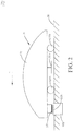
- the automatic mowing system 100a includes an automatic mower 10a and a wireless charging station 20a cooperating therewith, the automatic mower 10a and the wireless charging station 20a are both located in a to-be-cut region 30, and the to-be-cut region 30 is a lawn to be processed by a user.
- the wireless charging station 20a may also be located in another region outside the to-be-cut region 30. That is to say, it is ok as long as the wireless charging station 20a is in a movement range accessible to the automatic mower 10a.
- the automatic mower 10a includes an enclosure 11a, a mobile device 12a, a cutting device 13a, a battery pack 14a, and a wireless electric energy receiver 15a; the battery pack 14a is fixed into the enclosure 11a and electrically connected with the mobile device 12a and the cutting device 13a, to provide power required by operation of the mobile device 12a and the cutting device 13a; the battery pack 14a is electrically connected with the wireless electric energy receiver 15a, to acquire charging power from the wireless electric energy receiver 15a.
- the enclosure 11a includes a head 111a and a tail 112a as well as a top 113a and a bottom 114a connected between the head 111a and the tail 112a and opposite each other, a receiving chamber 115a is formed between the top 113a and the bottom 114a, and the battery pack 14a is removably disposed in the receiving chamber 115a.
- the mobile device 12a includes a mobile mechanism 121a and a mobile motor 122a that drives the mobile mechanism 121a to operate; in this embodiment, the mobile mechanism 121a includes multiple rollers which are rotatably disposed below the bottom 114a to support the whole enclosure 11a, and the mobile motor 122a is fixed into the receiving chamber 115a and electrically connected with the battery pack 114a; after acquiring the output power of the battery pack, the mobile motor 121a drives the rollers to roll and then drives the enclosure 11a to move in the to-be-cut region 30.
- the rollers may also be disposed on two sides of the enclosure 11a
- the mobile mechanism 121a may also use other conventional mobile mechanisms such as a track mechanism, and it is only necessary to maintain that the mobile mechanism 121a can stably support and drive the enclosure 11a to move, which is not repeated herein.
- the enclosure 11a has a lengthwise direction T from the tail 112a to the head 111a, the mobile device 12a drives the automatic mower 10a to make conventional movement, and the direction of the conventional movement is the same as that of the lengthwise direction T.
- the mobile device 12a further includes a steering module (not shown) and a reversing module (not shown) that controls the automatic mower 10a to adjust the movement direction to perform an obstacle avoiding operation, the steering module and the reversing module match the mobile mechanism 121a, regulate the mobile mechanism 121a when there is an obstacle ahead or it is necessary to change to advance towards the target, and then drive the mobile mechanism 121a to steer or reverse through the mobile motor 122a, thus achieving free movement of the automatic mower 10a in the to-be-cut region 30.
- a steering module (not shown) and a reversing module that controls the automatic mower 10a to adjust the movement direction to perform an obstacle avoiding operation
- the steering module and the reversing module match the mobile mechanism 121a, regulate the mobile mechanism 121a when there is an obstacle ahead or it is necessary to change to advance towards the target, and then drive the mobile mechanism 121a to steer or reverse through the mobile motor 122a, thus achieving free movement of the automatic mower 10a in the to-be-cut region
- the "lengthwise direction” herein is not limited to the lengthwise direction T from the tail 112a to the head 111a described previously, which may also be a direction opposite to the lengthwise direction T and from the head 111a to the tail 112a, which is a technology well-known to those of ordinary skill in the art and is not repeated herein.
- the cutting device 13a includes a cutter 131a and a cutting motor 132a that drives the cutter 131a to rotate, the cutting motor 132a is fixed into the receiving chamber 115a and electrically connected with the battery pack 14a, and an output shaft of the cutting motor 132a extends and penetrates the bottom 114a, so that the cutter 131a is located below the enclosure 11a; the cutting motor 132a, after acquiring the power output by the battery pack 14a, drives the cutter 132a to rotate, which automatically trims the to-be-cut region 30 while achieving free movement of the automatic mower 10a on the to-be-cut region 30.
- the automatic mower 10a further includes a mounting portion 16a connected onto the enclosure 11a, the wireless electric energy receiver 15a uses a magnetic induction coil which is mounted in the mounting portion 16a and close to an outer surface of the mounting portion 16a, and the wireless electric energy receiver 15a is disposed on the enclosure 11a through the mounting portion 16a, to jointly move with the automatic mower 10a.
- the automatic mower 10a further includes a control circuit 17a, the mobile motor 122a and the cutting motor 132a are both connected to the battery pack 14a through the control circuit 17a, and the power output by the battery pack 14a to the mobile motor 122a and the cutting motor 132a is adjusted through the control circuit 17a, to drive and shut down the cutting motor 132a and the mobile motor 122a according to different working conditions, causing movement and cutting of the automatic mower 10a more intelligent; even the control circuit 17a may further connect the wireless electric energy receiver 15a and the battery pack 14a, and then regulate a charging current for the battery pack 14a, preventing overcharge of the battery pack 14a, which is not repeated herein.
- control circuit 17a includes a switch module, a battery pack undervoltage and overcurrent protection module, a load current detection module, a motor speed control module, an obstacle impact identification module and other common functional modules, which is a technology well-known to those of ordinary skill in the art and is not repeated herein.
- the wireless charging station 20a includes a wireless electric energy transmitter 21a that acquires an AC signal from an external power source (not shown); the wireless electric energy transmitter 21a also uses a magnetic induction coil, and when the wireless electric energy transmitter 21a and the wireless electric energy receiver 15a are aligned, power output by the external power source can be transferred to the wireless electric energy receiver 15a through energy transfer such as electromagnetic induction and magnetic resonance through the two magnetic induction coils of the wireless electric energy transmitter 21a and the wireless electric energy receiver 15a, to complete charging for the battery pack 14a, which is a technology well-known to those of ordinary skill in the art and is not repeated herein.
- the height of the wireless charging station 20a located above the ground is 0.
- the wireless charging station 20a is completely located below the ground, and the wireless charging station 20a is completely located in the to-be-cut region 30.
- the automatic mower 10a As the wireless charging station 20a is completely located below the ground of the to-be-cut region 30, whether the automatic mower 10a randomly gets close to the wireless charging station 20a or intentionally directly returns to the wireless charging station 20a for charging in the process of moving in the to-be-cut region 30, the automatic mower 10a always can freely pass through or stay above the wireless charging station 20a, and the cutter 131a would not impact the wireless charging station 20a; so that the automatic mower 10a is movable to: the enclosure 11a can completely overlap with the wireless charging station 20a in the lengthwise direction T of the enclosure 11a, achieving that the to-be-cut region 30 has no cutting blind corner, and ensuring integrity and beauty of the lawn on the to-be-cut region 30.
- the wireless charging station 20a may also be merely partially located in the to-be-cut region 30, that is, the wireless charging station 20a may be disposed across a boundary line of the to-be-cut region 30, which does not affect wireless charging for the automatic mower 10a and is not repeated herein.
- the wireless electric energy receiver 15a is close to the head 111a of the automatic mower 10a, so that, when the automatic mower 10a returns to the wireless charging station 20a, the wireless electric energy receiver 15a and the wireless electric energy transmitter 21a can be aligned and matched faster, improving the charging efficiency of the automatic mower 10a.
- the wireless electric energy receiver 15a may also be close to the tail 112a of the automatic mower 10a or other positions, as long as it avoids that the mounting portion 16a interferes with rotation of the cutter 131a, which is not repeated herein.
- the automatic mowing system 100a further includes a regulating mechanism 18a which is connected between the wireless electric energy receiver 15a and the enclosure 11a; specifically, the regulating mechanism 18a is fixed onto the enclosure 11a and connected with the mounting portion 16a, and the regulating mechanism 18a can drive the mounting portion 16a to move relative to the enclosure 11a, to achieve regulation on the position of the wireless electric energy receiver 15a relative to the enclosure 11a.
- the regulating mechanism 18a is electrically connected with the control circuit 17a; after the automatic mower 10a returns to the wireless charging station 20 and completes matching between the wireless electric energy receiver 15a and the wireless electric energy transmitter 21a, the regulating mechanism 18a can drive the wireless electric energy receiver 15a to move along a vertical direction towards the wireless electric energy transmitter 21a; as in this embodiment, the wireless charging station 20a is completely located below the ground, when the wireless electric energy receiver 15a clings to the ground, the wireless electric energy receiver 15a and the wireless electric energy transmitter 21a are closest, to ensure the efficiency of wireless charging.
- the regulating mechanism 18a drives the wireless electric energy receiver 15a to move upwards away from the ground and return to a position before a move-down operation, to enable the automatic mower 10a to smoothly leave from above the wireless charging station 20a subsequently, without being interfered by the ground.
- the regulating mechanism may also be located in the wireless charging station, the wireless charging station has a movable portion receiving the wireless electric energy transmitter 21a and a base portion mounted to the ground, and the regulating mechanism is located between the movable portion and the base portion; after matching between the wireless electric energy receiver 15a and the wireless electric energy transmitter 21a is completed, the movable portion receiving the wireless electric energy transmitter 21a is lifted upwards, which may also cause the wireless electric energy receiver 15a and the wireless electric energy transmitter 21a to be closer; further, the regulating mechanism may also be connected with both the wireless electric energy receiver 15a and the wireless electric energy transmitter 21a, to control them to be close to or away from each other, which can also improve the efficiency of wireless charging.
- the regulating mechanism 18a is not limited to driving the wireless electric energy receiver 15a or the wireless electric energy transmitter 21a to move in the vertical direction, and may also drive the wireless electric energy receiver 15a and the wireless electric energy transmitter 21a to move in a horizontal direction, thus improving precision of matching between the wireless electric energy receiver 15a and the wireless electric energy transmitter 21a.
- the regulating mechanism 18a may employ multiple common transmission structures, such as worm and gear or bevel gear, and cooperate with infrared and other positioning structures to achieve rapidly and accurately driving the wireless electric energy receiver 15a and the wireless electric energy transmitter 21a to move in the vertical direction and the horizontal direction, which is a technology well-known to those of ordinary skill in the art and is not repeated herein.
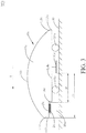
- the difference between the automatic mowing system 100b provided in the second embodiment of the present invention and the automatic mowing system 100a provided in the first embodiment is that: the wireless charging station 20b is only partially located below the ground of the to-be-cut region 30.
- the height of the wireless charging station 20b located above the ground of the to-be-cut region 30 is less than the minimum distance from the cutter 131b to the ground of the to-be-cut region 30.
- the minimum distance from the cutter 131b of the automatic mower 10b to the ground of the to-be-cut region 30 may be selected as 150 mm, 60 mm, 20 mm or other conventional heights, so that the automatic mower 10b can cut out lawns with different height in the to-be-cut region 30, thus making diversified trimming in conjunction with different varieties of grass; also, the height of the wireless charging station 20b located above the ground of the to-be-cut region 30 is also adjusted adaptively, to make it less than or equal to 150 mm, or less than or equal to 60 mm, or less than or equal to 20 mm; so that the wireless charging station 20b can adapt to the automatic mower 10b with multiple cutting heights, thereby improving adaptability of the automatic mowing system 100b.
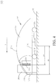
- the difference between the automatic mowing system 100c provided in the third embodiment of the present invention and the automatic mowing systems 100a and 100b in the first and second embodiments is that: the height of the wireless charging station 20c located above the ground of the to-be-cut region 30 is greater than the minimum distance between the cutter 131c and the ground.
- the enclosure 11c of the automatic mower 10c is provided thereon with a guide notch 116c which extends from an edge 117c of the enclosure 11c towards the inside of the enclosure 11c.
- the guide notch 116c is located at the head 111c of the enclosure 11c, and extends along an opposite direction of the lengthwise direction T of the enclosure 11c towards the interior of the enclosure 11c; whether the automatic mower 10c, under the driving of the mobile mechanism 121c, randomly gets close to the wireless charging station 20c or intentionally directly returns to the wireless charging station 20c for charging, at least one part of the wireless charging station 20c can be received through the guide notch 116c, so that the automatic mower 10c is movable to: the enclosure 11c and the wireless charging station 20c at least partially overlap in the lengthwise direction T of the enclosure 11c.
- a distance D2 between the cutter 131c and the wireless charging station 20c is apparently smaller than a distance D1 between the cutter 131c and the head 111c, which solves the deficiency that, when the height of the wireless charging station 20c located above the ground exceeds the minimum distance between the cutter 131c and the ground, a cutting blind corner in the to-be-cut region 30 is large as the head 111c of the enclosure 11c abuts against the wireless charging station 20c.
- the trimming capability of the automatic mower 10c may also be improved correspondingly, which is not repeated herein.
- the guide notch 116c is disposed on the bottom 114c and extends from the bottom 114c towards the top 113c, which facilitates the wireless charging station 20c to rapidly enter the guide notch 116c and stay below the enclosure 11c.
- the guide notch 116c may also be located on the tail 112c of the enclosure 11c or other parts, and is not limited to extending along an opposite direction of the lengthwise direction T into the enclosure 11c, its extending direction may be adjusted adaptively according to user demands, site conditions and the like, and it is only necessary to maintain that the guide notch 116c extends from an edge 117c of the enclosure 11c into the enclosure 11c and adaptively adjust a return movement direction of the automatic mower 10c to reverse or make other movements along the extending direction of the guide notch 116c, which is not repeated herein.
- the wireless electric energy receiver 15c is located in the guide notch 116c, so that the wireless electric energy receiver 15c is in communication with the periphery of the enclosure 11c, which facilitates it to match the wireless electric energy transmitter 21c staying in the guide notch 116c, thereby achieving wireless charging for the battery pack.
- the wireless electric energy receiver 15c may also be detached from the guide notch 116c through the regulating mechanism, when there is no charging demand, the wireless electric energy receiver 15c may be put away, avoiding that the wireless electric energy receiver 15c is damaged by the wireless charging station 20c, and when there is a charging demand, the wireless electric energy receiver 15c enters the guide notch 116c, to ensure the efficiency of wireless charging.
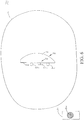
- the difference between the automatic mowing system 100d provided in the fourth embodiment of the present invention and the automatic mowing system 100c in the third embodiment is that: the height of the wireless charging station 20d located above the ground of the to-be-cut region 30 is greater than the minimum distance between the cutter 131d and the ground, and higher than part of the enclosure 11d.
- the guide notch 116d is also located at the head 111d, extends from an edge 117d of the head 111d along an opposite direction of the lengthwise direction T of the enclosure 11d towards the inside of the enclosure 11d, guides the guide notch 116d to extend from the bottom 114d to the top 113d, and penetrates the bottom 114d and the top 113d.
- the automatic mower 10d under the driving of the mobile mechanism 121d, randomly gets close to the wireless charging station 20d or intentionally directly returns to the wireless charging station 20d for charging, at least one part of the wireless charging station 20d can be received through the guide notch 116d, so that the automatic mower 10d is movable to: the enclosure 11d and the wireless charging station 20d at least partially overlap in the lengthwise direction T of the enclosure 1 Id.
- a distance D3 between the cutter 131d and the wireless charging station 20d is smaller than a distance D1 between the cutter 131d and the head 111d, which solves the deficiency that, when the height of the wireless charging station 20d exceeds the distance from the cutter 131d to the ground and part of the enclosure 11d, a cutting blind corner in the to-be-cut region 30 is large as the head 111d of the enclosure 11d abuts against the wireless charging station 20d.
- the wireless electric energy receiver 15d is also located in the guide notch 116d, so that the wireless electric energy receiver 15d is in communication with the periphery of the enclosure 11d, which facilitates it to match the wireless electric energy transmitter 21d staying in the guide notch 116d, thereby achieving wireless charging for the battery pack.
- the automatic mowing system provided in the present invention, by completely locating the wireless charging station below the ground, or setting the height thereof above the ground to be less than the height of the cutter relative to the ground, or setting a guide notch on the enclosure of the automatic mower and other multiple means mentioned in the foregoing embodiments, the enclosure of the automatic mower at least partially overlaps with the wireless charging station in the lengthwise direction T of the enclosure, which achieves that the automatic mower can trim the lawn closer to and even completely cover the region where the wireless charging station is, reduces and even completely removes the cutting blind corner in the to-be-cut region, ensures integrity of the lawn in the to-be-cut region, and improves the working capability of the automatic mowing system.
- the cutting element performing the mowing action may be a blade or a trimming line.
- the device transfers driving power of the cutting motor to the cutting element may be a cutter, a trimming head or the like.
- the cutter or the trimming head has the same function, that is, transfer the driving force to the cutting element, which may be collectively referred to as a connection tray.
- the difference between the automatic mowing system 100e provided in the fifth embodiment of the present invention and the automatic mowing system 100a provided in the first embodiment is that: the wireless charging station 20e is located in a region outside the to-be-cut region 30. Although the region is not the to-be-cut region 30, it belongs to a region within a movable range of the automatic mower 10e. Those skilled in the art may understand that the wireless charging station 20e may be partially or wholly located in the region within a movable range of the automatic mower 10e.
- the automatic mower 10e In a situation that the top of the wireless charging station 20e is lower than the bottom of the cutting device 13e, the automatic mower 10e always can freely pass through or stay above the wireless charging station 20e, and the cutting device would not impact the wireless charging station 20e; so that the automatic mower 10e is movable to: the enclosure 11e can completely overlap with the wireless charging station 20e in the lengthwise direction T of the enclosure 11e, achieving that the automatic mower 10e has no cutting blind corner in the movable range and ensuring integrity and beauty of the lawn in the movement range of the automatic mower 10e.
- That the wireless charging station 20e is lower than the cutting device 13e includes, but is not limited to, the following situations: 1) the wireless charging station 20e is wholly located in a position below the ground, the height of the top thereof coming out of the ground is zero, the height apparently from the ground is a negative value, while the height of the bottom of the cutting device 13e to the ground is a positive value; therefore, the wireless charging station 20e is lower than the cutting device; 2) the wireless charging station 20e is at least partially located above the ground, that is, the height of the top of the wireless charging station 20e to the ground is a positive value, but the height value is lower than that of the bottom of the cutting device 13e to the ground; 3) the wireless charging station 20e is completely located above the ground, and the height value of the top of the wireless charging station 20e relative to the ground is lower than the height value of the bottom of the cutting device 13e to the ground.
- the wireless electric energy transmitter 21e When the wireless charging station 20e is completely located below the ground, the wireless electric energy transmitter 21e is located below the ground. When the wireless charging station 20e is partially located above the ground, the wireless electric energy transmitter 21e may be located below the ground, and may also be at least partially located above the ground. When the wireless charging station 20e is completely located above the ground, the wireless electric energy transmitter 21e is completely located above the ground.
- the cutting device 13f includes a cutting element that performs a mowing action, and a connection tray 131f that transfers driving power from the cutting motor 132f to the cutting element.
- the cutting element may be a trimming line, a cutting blade or the like.
- the connection tray 131f may be a trimming head or a cutter.
- the wireless electric energy receiver 15f is disposed above the connection tray 131f.
- the cutting device 13g includes a cutting element that performs a mowing action, and a connection tray 131g that transfers driving power from the cutting motor 132g to the cutting element.
- the wireless electric energy receiver 15g is disposed in the connection tray 131g.
- the structure causes the space utilization rate to be the highest.
- the cutting element may be a blade or a trimming line.
- the connection tray 131g may be a trimming head or a cutter.
- the difference between the automatic mowing system 100h provided in the eighth embodiment of the present invention and the automatic mowing system 100a provided in the first embodiment is that: the automatic mower 10h further includes a boundary sensor 19h.
- the boundary sensor 19h receives information representing the boundary of the to-be-cut region 30, so as to identify the position of the automatic mower 10h relative to the boundary of the to-be-cut region 30.
- the wireless electric energy receiver 15h is separated from the boundary sensor 19h, so that the automatic mower 10h has sufficient space to dispose the boundary sensor 19h and the wireless electric energy receiver 15h.
- the cutting device 13h includes a cutting element that performs a mowing action, and a connection tray 131h that transfers driving power from the cutting motor 132h to the cutting element.
- the cutting device may be a trimming rope or a cutting blade.
- the connection tray 131h may be a trimming head or a cutter.
- the automatic mowing system 100h further includes a boundary device that delimits the to-be-cut region 30 of the automatic mowing system 100h, and the boundary device sends a boundary signal.
- the boundary sensor 19h identifies the position relative to the boundary of the to-be-cut region 30 by receiving a boundary signal.
- the boundary sensor 19h includes a video pickup device, which judges the position of the automatic mowing system 100h relative to the boundary of the to-be-cut region 30 by picking up image information of surrounding environments of the automatic mowing system 100h.
- the boundary sensor 19h and the wireless electric energy receiver 15h are disposed at a front portion and a rear portion along the lengthwise direction T of the enclosure 11h respectively.
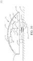
- the difference between the ninth embodiment as shown in FIG. 10 and the eighth embodiment lies in that one of the boundary sensor 19i and the wireless electric energy receiver 15i is disposed above the connection tray 131i. Meanwhile, the other one of the boundary sensor 19i and the wireless electric energy receiver 15i is disposed below the connection tray 131i.
- the boundary sensor 19i is disposed above the connection tray 131i, and the wireless electric energy receiver 15i is disposed below the connection tray 131i.
- the boundary sensor and the wireless electric energy receiver may be disposed at a front portion and a rear portion along a travel direction of the automatic mower respectively. The travel direction of the automatic mower may be the same as or different from the lengthwise direction T of the enclosure.
- connection tray above the connection tray may be any position on a space extending upwards from the top of the connection tray along a vertical direction to an outer surface of the enclosure.
- connection tray below the connection tray may be any position on a space extending downwards from the bottom of the connection tray along the vertical direction to ground.
- the height from the top of the wireless charging station to the ground is lower than the height from the bottom of the cutting device to the ground.
- the fifth to ninth embodiments may be improved as follows: the height of the top of the wireless charging station located above the ground is greater than the minimum distance between the cutting device and the ground.
- the third embodiment of the present invention for the specific structure of the automatic mowing system.
- the fifth to ninth embodiments may also be improved as follows: the height of the wireless charging station located in the movement range of the automatic mower is higher than part of the enclosure while greater than the minimum distance between the cutting device and the ground.
- the size of the wireless electric energy receiver along the width direction of the automatic mower is less than or equal to 50 cm, and such a width enables the wireless electric energy receiver to be completely received in the enclosure.
- the size may also be 40 cm, 30 cm, 20 cm, 10 cm or any other sizes, and the specific size is set according to the demand for charging power.
- the wireless electric energy receiver is a round disc.
- the diameter of the wireless electric energy receiver is less than or equal to 50 cm.
- the diameter may also be 40 cm, 30 cm, 20 cm, 10 cm or any other sizes, and the specific size is set according to the demand for charging power.
- the battery pack may also be other energy storage devices such as a super-capacitor. The energy storage devices and the battery pack may be collectively referred to as energy storage unit.
Landscapes
- Engineering & Computer Science (AREA)
- Power Engineering (AREA)
- Transportation (AREA)
- Mechanical Engineering (AREA)
- Life Sciences & Earth Sciences (AREA)
- Environmental Sciences (AREA)
- Computer Networks & Wireless Communication (AREA)
- Harvester Elements (AREA)
Abstract
Description
- The present invention relates to the field of gardening equipment, and in particular, to a wireless charging station, an automatic mower matched with the wireless charging station, and an automatic mowing system using the wireless charging station and the automatic mower.
- The existing automatic mower generally includes an enclosure, a mobile device, a cutting device, and a battery pack, and the battery can provide electric energy required by operation of the mobile device and the cutting device. In use, a to-be-cut region for the automatic mower to move is preset on a lawn, a charging station is disposed in the to-be-cut region, when it is detected that the power of the battery pack is low, the automatic mower can automatically return to the charging station and connect a charging terminal in the charging station, to achieve charging of the battery pack, and after it is subsequently detected that the power in the battery pack meets the operation demand, the automatic mower would automatically drive away from the charging station, to continue to complete trimming of the lawn in the to-be-cut region.
- The existing charging station generally also has a base board for the automatic mower to stay during charging and a baffle for stopping the automatic mower from driving away from the base board, and when the automatic mower returns to the charging station for charging, it first drives on the base board and connects the charging terminal on the baffle, and completely stops moving under the blocking of the baffle, causing the charging of the battery pack to be more stable. However, the automatic mower, in the process of moving to trim the lawn, may automatically stay away to prevent damage to the mower after contacting the baffle, resulting in that the lawn on the periphery of the baffle cannot be trimmed, and in order to ensure that the baffle can stably stop movement of the automatic mower when the automatic mower charges, the baffle generally is higher and wider than the automatic mower, so that the to-be-cut region always has a large-sized cutting blind corner, thereby reducing user experience.
- Therefore, it is necessary to propose a new charging station to solve the above problems. Correspondingly, it is also necessary to provide a new automatic mower and an automatic mowing system having the charging station and the automatic mower, to jointly solve the above technical problems.
- The present invention provides a wireless charging station having no interference with the cutting work of an automatic mower.
- In order to achieve the above invention purpose, the present invention provides a wireless charging station, for charging an automatic mower, the automatic mower comprising a cutting device, an energy storage unit and a wireless electric energy receiver, the wireless electric energy receiver being electrically connected with the energy storage unit, the wireless charging station comprises a wireless electric energy transmitter, the wireless charging station is at least partially located in a movement range of the automatic mower, and the top of the wireless charging station is lower than the bottom of the cutting device.
- In order to achieve the above invention purpose, the present invention also provides a wireless charging station, for charging an automatic mower, the automatic mower comprising a cutting device, an energy storage unit and a wireless electric energy receiver, the wireless electric energy receiver being electrically connected with the energy storage unit, the wireless charging station comprises a wireless electric energy transmitter, the wireless charging station is at least partially located in a movement range of the automatic mower, and the top of the wireless electric energy transmitter is lower than the bottom of the cutting device.
- In order to achieve the above invention purpose, the present invention also provides a wireless charging station, for charging an automatic mower, the automatic mower comprising a cutting device, an energy storage unit and a wireless electric energy receiver, the wireless electric energy receiver being electrically connected with the energy storage unit, the wireless charging station comprises a wireless electric energy transmitter, the wireless charging station is at least partially located in a movement range of the automatic mower, and the height of the wireless charging station above the ground is less than the minimum distance between the cutting device and the ground.
- Preferably, the height of the wireless charging station above the ground is less than or equal to 150 mm.
- Preferably, the height of the wireless charging station above the ground is less than or equal to 60 mm.
- Preferably, the height of the wireless charging station above the ground is less than or equal to 20 mm.
- Preferably, the wireless charging station is completely located in the movement range of the automatic mower.
- In order to achieve the above invention purpose, the present invention also provides a wireless charging station, for charging an automatic mower, the automatic mower comprising a cutting device, an energy storage unit and a wireless electric energy receiver, the wireless electric energy receiver being electrically connected the the energy storage unit, the wireless charging station comprises a wireless electric energy transmitter, the wireless charging station is at least partially located in a movement range of the automatic mower, and the wireless electric energy transmitter is located below the ground.
- In order to achieve the above invention purpose, the present invention also provides a wireless charging station, for charging an automatic mower, the automatic mower comprising a cutting device, an energy storage unit and a wireless electric energy receiver, the wireless electric energy receiver being electrically connected with the energy storage unit, the wireless charging station comprises a wireless electric energy transmitter, the wireless charging station is at least partially located in a movement range of the automatic mower, and the wireless charging station is located below the ground.
- Preferably, the wireless charging station is completely located in the movement range of the automatic mower.
- The present invention provides an automatic mowing system, comprising a wireless charging station having no interference with the cutting work of an automatic mower.
- In order to achieve the above invention purpose, the present invention provides an automatic mowing system, the automatic mowing system comprises: an automatic mower comprising: an enclosure; a mobile device comprising a mobile mechanism that supports the enclosure and drives the enclosure to move; a cutting device comprising a cutter located below the enclosure; an energy storage unit received in the enclosure and used for providing power for the mobile device and the cutting device; and a wireless electric energy receiver disposed on the enclosure and electrically connected with the energy storage unit; and the wireless charging station as mentioned before, the wireless electric energy transmitter in the wireless charging station selectively matches the wireless electric energy receiver to charge the energy storage unit.
- In order to achieve the above invention purpose, the present invention also provides an automatic mowing system, the automatic mowing system comprises: an automatic mower comprising: an enclosure; a cutting device received in the enclosure, comprising a connection tray; an energy storage unit providing power for the cutting device; a wireless electric energy receiver electrically connected with the energy storage unit; and the wireless charging station as mentioned before, the wireless electric energy transmitter in the wireless charging station selectively matches the wireless electric energy receiver to charge the energy storage unit.
- Preferably, the wireless electric energy receiver is disposed above the connection tray.
- Preferably, the wireless electric energy receiver is disposed in the connection tray.
- Preferably, the size of the wireless electric energy receiver along the width direction of the automatic mower is less than or equal to 50 cm.
- Preferably, the automatic mover further comprises a boundary sensor, the boundary sensor receives a signal representing a boundary of a to-be-cut region and identifies the position of the automatic mower relative to the boundary of the to-be-cut region, and the wireless electric energy receiver is separated from the boundary sensor.
- Preferably, the boundary sensor and the wireless electric energy receiver are disposed at a front portion and a rear portion along a travel direction of the automatic mower respectively.
- Preferably, one of the boundary sensor and the wireless electric energy receiver is disposed above the connection tray, and the other one of the boundary sensor and the wireless electric energy receiver is disposed below the connection tray.
- In order to achieve the above invention purpose, the present invention also provides an a wireless charging station, for charging an automatic mower, the automatic mower comprising a cutting device, the wireless charging station comprises a wireless electric energy transmitter, the wireless charging station is at least partially located in a movement range of the automatic mower, and the height of the wireless charging station above the ground is less than the minimum distance between the cutting device and the ground.
- Preferably, the height of the wireless charging station above the ground is less than or equal to 150 mm.
- Preferably, the height of the wireless charging station above the ground is less than or equal to 60 mm.
- Preferably, the height of the wireless charging station above the ground is less than or equal to 20 mm.
- Preferably, the wireless charging station is completely located below the ground.
- Preferably, the wireless charging station is completely located in the to-be-cut region.
- In order to achieve the above invention purpose, the present invention also provides an automatic mowing system, the automatic mowing system comprises: an automatic mower comprising: an enclosure; a mobile device comprising a mobile mechanism that supports the enclosure and drives the enclosure to move; a cutting device comprising a cutter located below the enclosure; an battery pack received in the enclosure and used for providing power for the mobile device and the cutting device; and a wireless electric energy receiver disposed on the enclosure and electrically connected with the battery pack; and the wireless charging station as mentioned before, the wireless electric energy transmitter in the wireless charging station selectively matches the wireless electric energy receiver to charge the battery pack.
- Compared with the prior art, in the present invention, the height of the wireless charging station relative to the ground is lower than the height of the cutter relative to the ground, enabling the cutter to process the area near the wireless charging station, thus improving the mowing range of the automatic mower to lawn.
- The present invention provides an automatic mowing system, comprising a wireless charging station reducing interference with the cutting work of an automatic mower.
- In order to achieve the above invention purpose, the present invention provides an automatic mowing system, the automatic mowing system comprises: an automatic mower comprising: an enclosure; a cutting device received in the enclosure, comprising a connection tray; an energy storage unit providing power for the cutting device; a wireless electric energy receiver electrically connected with the energy storage unit; and a wireless charging station comprising: a wireless electric energy transmitter selectively matching the wireless electric energy receiver to charge the energy storage unit; the wireless charging station being at least partially located in a movement range of the automatic mower, the enclosure comprising a lengthwise direction, and the automatic mower being movable to: the enclosure and the wireless charging station at least partially overlap in the lengthwise direction.
- In order to achieve the above invention purpose, the present invention also provides an automatic mowing system, the automatic mowing system comprises: an automatic mower comprising: an enclosure; a cutting device received in the enclosure, comprising a connection tray; an energy storage unit providing power for the cutting device; a wireless electric energy receiver electrically connected with the energy storage unit; and a wireless charging station comprising: a wireless electric energy transmitter selectively matching the wireless electric energy receiver to charge the energy storage unit; the wireless charging station being at least partially located in a movement range of the automatic mower, the automatic mower being movable to a specific position, and in the specific position, projections of the enclosure and the wireless charging station at least partially overlap in a vertical direction.
- In order to achieve the above invention purpose, the present invention also provides an automatic mowing system, the automatic mowing system comprises: an automatic mower comprising: an enclosure; a cutting device received in the enclosure, comprising a connection tray; an energy storage unit providing power for the cutting device; a wireless electric energy receiver disposed on the enclosure and electrically connected with the energy storage unit; and a wireless charging station comprising: a wireless electric energy transmitter selectively matching the wireless electric energy receiver to charge the energy storage unit; the wireless charging station being at least partially located in a movement range of the automatic mower, the automatic mower being movable to a specific position, and in the specific position, projections of the enclosure and the wireless charging station at least partially overlap in a horizontal direction.
- Preferably, the wireless charging station is completely located below the ground.
- Preferably, the height of the wireless charging station located above the ground is less than the minimum distance between the cutting device and the ground.
- Preferably, the minimum distance between the cutting device and the ground is 150 mm or 60 mm or 20 mm.
- Preferably, the height of the wireless charging station located above the ground is greater than the minimum distance between the cutting device and the ground.
- Preferably, the automatic mower comprises a guide notch extending from an edge of the enclosure into the enclosure, and the automatic mower is movable to: the wireless charging station is at least partially located in the guide notch.
- Preferably, the enclosure comprises a head and a tail opposite each other, and the guide notch extends from an edge of the head into the enclosure along the lengthwise direction.
- Preferably, the enclosure comprises a top and a bottom opposite each other, and the guide notch is located at the bottom and extends towards the top.
- Preferably, the guide notch extends from the bottom to the top, and causes the bottom and the top to connect.
- Preferably, the wireless electric energy receiver is located in the guide notch.
- Preferably, the automatic mowing system comprises a regulating mechanism connecting the wireless electric energy receiver and/or the wireless electric energy transmitter, and when the automatic mower moves to that the enclosure at least partially overlaps with the wireless charging station in the lengthwise direction and stops moving, and the regulating mechanism selectively regulates a relative distance between the wireless electric energy receiver and the wireless electric energy transmitter.
- Preferably, the wireless electric energy receiver is disposed above the connection tray.
- Preferably, the wireless electric energy receiver is disposed in the connection tray.
- Preferably, the size of the wireless electric energy receiver along the width direction of the automatic mower is less than or equal to 50 cm.
- Preferably, the automatic mower further comprises a boundary sensor, the boundary sensor receives a signal representing a boundary of a to-be-cut region and identifies the position of the automatic mower relative to the boundary of the to-be-cut region, and the wireless electric energy receiver is separated from the boundary sensor.
- Preferably, the boundary sensor and the wireless electric energy receiver are disposed at a front portion and a rear portion along a travel direction of the automatic mower respectively.
- Preferably, one of the boundary sensor and the wireless electric energy receiver is disposed above the connection tray, and the other one of the boundary sensor and the wireless electric energy receiver is disposed below the connection tray.
- In order to achieve the above invention purpose, the present invention also provides an automatic mowing system, the automatic mowing system comprises: an automatic mower comprising: an enclosure; a mobile device comprising a mobile mechanism that supports the enclosure and drives the enclosure to move; a cutting device comprising a cutter located below the enclosure; an battery pack received in the enclosure and used for providing power for the mobile device and the cutting device; a wireless electric energy receiver disposed on the enclosure and electrically connected with the battery pack; and a wireless charging station comprising: a wireless electric energy transmitter selectively matching the wireless electric energy receiver to charge the battery pack; the wireless charging station being at least partially located in a movement range of the automatic mower, the enclosure comprising a lengthwise direction, and the automatic mower being movable to: the enclosure and the wireless charging station at least partially overlap in the lengthwise direction.
- Preferably, the wireless charging station is completely located below the ground.
- Preferably, the height of the wireless charging station located above the ground is less than the minimum distance between the cutting device and the ground.
- Preferably, the minimum distance between the cutting device and the ground is 150 mm or 60 mm or 20 mm
- Preferably, the height of the wireless charging station located above the ground is greater than the minimum distance between the cutting device and the ground.
- Preferably, the automatic mower comprises a guide notch extending from an edge of the enclosure into the enclosure, and the automatic mower is movable to: the wireless charging station is at least partially located in the guide notch.
- Preferably, the enclosure comprises a head and a tail opposite each other, and the guide notch extends from an edge of the head into the enclosure along the lengthwise direction.
- Preferably, the enclosure comprises a top and a bottom opposite each other, and the guide notch is located at the bottom and extends towards the top.
- Preferably, the guide notch extends from the bottom to the top, and causes the bottom and the top to connect.
- Preferably, the wireless electric energy receiver is located in the guide notch.
- Preferably, the automatic mowing system comprises a regulating mechanism connecting the wireless electric energy receiver and/or the wireless electric energy transmitter, and when the automatic mower moves to that the enclosure at least partially overlaps with the wireless charging station in the lengthwise direction and stops moving, and the regulating mechanism selectively regulates a relative distance between the wireless electric energy receiver and the wireless electric energy transmitter.
- Compared with the prior art, the automatic mower in the automatic mowing system in the present invention, can mow the lawn closer to the charging station , reducing or even completely eliminating the cutting blind corner in the movement range, thus improving the ability of the automatic mower to mow the lawn.
- The present invention provides an automatic mower, comprising a wireless electric energy receiver having an optimized setting position.
- In order to achieve the above invention purpose, the present invention provides an automatic mower, the automatic mower comprises an enclosure, a cutting device received in the enclosure and comprising a connection tray, an energy storage unit providing power for the cutting device, and a wireless electric energy receiver selectively acquiring wireless charging energy to charge the energy storage unit, and the wireless electric energy receiver is disposed above the connection tray.
- In order to achieve the above invention purpose, the present invention also provides an automatic mower, the automatic mower comprises an enclosure, a cutting device received in the enclosure and comprising a connection tray, an energy storage unit providing power for the cutting device, and a wireless electric energy receiver selectively acquiring wireless charging energy to charge the energy storage unit, and the wireless electric energy receiver is disposed in the connection tray.
- Preferably, the size of the wireless electric energy receiver along the width direction of the automatic mower is less than or equal to 50 cm.
- Preferably, the automatic mower further comprises a boundary sensor, the boundary sensor receives a signal representing a boundary of a to-be-cut region and identifies the position of the automatic mower relative to the boundary of the to-be-cut region, and the wireless electric energy receiver is separated from the boundary sensor.
- Preferably, the boundary sensor and the wireless electric energy receiver are disposed at a front portion and a rear portion along a travel direction of the automatic mower respectively.
- Preferably, one of the boundary sensor and the wireless electric energy receiver is disposed above the connection tray, and the other one of the boundary sensor and the wireless electric energy receiver is disposed below the connection tray.
- The present invention further provides an automatic mowing system, the automatic mowing system comprising an automatic mower, the automatic mower comprising a wireless electric energy receiver having an optimized setting position.
- In order to achieve the above invention purpose, the present invention provides an automatic mowing system, the automatic mowing system comprising a wireless charging station and an automatic mower, the wireless charging station comprising a wireless electric energy transmitter, the automatic mower is the automatic mower as mentioned before, and the wireless electric energy receiver selectively matches the wireless electric energy transmitter to acquire wireless charging energy.
- Preferably, the top of the wireless charging station is lower than the bottom of the cutting device.
- Preferably, the height of the wireless charging station located above the ground is less than the minimum distance between the cutting device and the ground.
- Preferably, the wireless charging device is located below the ground.
- Preferably, the enclosure comprises a lengthwise direction, and the automatic mower is movable to: the enclosure and the wireless charging station at least partially overlap in the lengthwise direction.
- Preferably, the automatic mower is movable to a specific position, and in the specific position, projections of the enclosure and the wireless charging station at least partially overlap in a vertical direction.
- Preferably, the automatic mower is movable to a specific position, and in the specific position, projections of the enclosure and the wireless charging station at least partially overlap in a horizontal direction
- In order to achieve the above invention purpose, the present invention also provides an automatic mower, the automatic mower comprises an enclosure, a cutting device received in the enclosure and comprising a connection tray, an energy storage unit providing power for the cutting device, a wireless electric energy receiver selectively acquiring wireless charging energy to charge the energy storage unit, and a boundary sensor, the boundary sensor receives a signal representing a boundary of a to-be-cut region and identifies the position of the automatic mower relative to the boundary of the to-be-cut region, and the wireless electric energy receiver is separated from the boundary sensor.
- Preferably, the boundary sensor and the wireless electric energy receiver are disposed at a front portion and a rear portion along a travel direction of the automatic mower respectively.
- Preferably, one of the boundary sensor and the wireless electric energy receiver is disposed above the connection tray, and the other one of the boundary sensor and the wireless electric energy receiver is disposed below the connection tray.
- Preferably, the size of the wireless electric energy receiver along the width direction of the automatic mower is less than or equal to 50 cm.
- Preferably, the wireless electric energy receiver is disposed above the connection tray.
- Preferably, the wireless electric energy receiver is disposed in the connection tray.
- In order to achieve the above invention purpose, the present invention also provides an automatic mowing system, the automatic mowing system comprising a wireless charging station and an automatic mower, the wireless charging station comprising a wireless electric energy transmitter, the automatic mower is the automatic mower as mentioned before, and the wireless electric energy receiver selectively matches the wireless electric energy transmitter to acquire wireless charging energy.
- Preferably, the top of the wireless charging station is lower than the bottom of the cutting device.
- Preferably, the height of the wireless charging station located above the ground is less than the minimum distance between the cutting device and the ground.
- Preferably, the wireless charging station is located below the ground.
- Preferably, the enclosure comprises a lengthwise direction, and the automatic mower is movable to: the enclosure and the wireless charging station at least partially overlap in the lengthwise direction.
- Preferably, the automatic mower is movable to a specific position, and in the specific position, projections of the enclosure and the wireless charging station at least partially overlap in a vertical direction.
- Preferably, the automatic mower is movable to a specific position, and in the specific position, projections of the enclosure and the wireless charging station at least partially overlap in a horizontal direction.
- Compared with the prior art, the position of the wireless electric energy receiver of the automatic mower provided in the present invention is set reasonably, making full use of the space inside the automatic mower, optimizing the structure of the automatic mower.
- The present invention provides an automatic mower, comprising a wireless electric energy receiver with an optimized size.
- In order to achieve the above invention purpose, the present invention provides an automatic mower, the automatic mower comprises an enclosure, a cutting device received in the enclosure and comprising a connection tray, an energy storage unit providing power for the cutting device, and a wireless electric energy receiver selectively acquiring wireless charging energy to charge the energy storage unit, and the size of the wireless electric energy receiver along the width direction of the automatic mower is less than or equal to 50 cm.
- Preferably, the wireless electric energy receiver is disposed above the connection tray.
- Preferably, the wireless electric energy receiver is disposed in the connection tray.
- Preferably, the automatic mower further comprises a boundary signal sensor, the boundary signal sensor receives a signal representing a boundary of a to-be-cut region and identifies the position of the automatic mower relative to the boundary of the to-be-cut region, and the wireless electric energy receiver is separated from the boundary signal sensor.
- Preferably, the boundary signal sensor and the wireless electric energy receiver are disposed at a front portion and a rear portion along a travel direction of the automatic mower respectively.
- Preferably, the boundary signal sensor and the wireless electric energy receiver is disposed above the connection tray, and the other one of the boundary signal sensor and the wireless electric energy receiver is disposed below the connection tray.
- The present invention further provides an automatic mowing system, the automatic mowing system comprising an automatic mower, the automatic mower comprising a wireless electric energy receiver with an optimized size.
- In order to achieve the above invention purpose, the present invention provides an automatic mowing system, the automatic mowing system comprising a wireless charging station and an automatic mower, the wireless charging station comprising a wireless electric energy transmitter, the automatic mower is the automatic mower as mentioned before, and the wireless electric energy receiver selectively matches the wireless electric energy transmitter to acquire wireless charging energy.
- Preferably, the top of the wireless charging station is lower than the bottom of the cutting device.
- Preferably, the height of the wireless charging station located above the ground is less than the minimum distance between the cutting device and the ground.
- Preferably, the wireless charging station is located below the ground.
- Preferably, the enclosure comprises a lengthwise direction, and the automatic mower is movable to: the enclosure and the wireless charging station at least partially overlap in the lengthwise direction.
- Preferably, the automatic mower is movable to a specific position, and in the specific position, projections of the enclosure and the wireless charging station at least partially overlap in a vertical direction.
- Preferably, the automatic mower is movable to a specific position, and in the specific position, projections of the enclosure and the wireless charging station at least partially overlap in a horizontal direction.
- Compared with the prior art, the size of the wireless electric energy receiver of the automatic mower provided in the present invention along the width direction of the automatic mower is less than or equal to 50 cm, enabling the wireless electric energy receiver to be completely received in the enclosure of the automatic mower, thus optimizing the structure of the automatic mower.
- The objectives, technical solutions, and beneficial effects of the present invention can be clearly obtained through the following detailed description of specific embodiments that can implement the present invention and in combination with the accompanying drawings.
-
FIG. 1 is a sectional view of an automatic mowing system in a first embodiment of the present invention; -
FIG. 2 is a side view of an automatic mowing system in a second embodiment of the present invention; -
FIG. 3 is a side view of an automatic mowing system in a third embodiment of the present invention; -
FIG. 4 is a side view of an automatic mowing system in a fourth embodiment of the present invention, wherein the head part is a section view; -
FIG. 5 is a top view of the automatic mowing system shown inFIG. 4 ; -
FIG. 6 is a top view of an automatic mowing system in a fifth embodiment of the present invention; -
FIG. 7 is a sectional view of an automatic mowing system in a sixth embodiment of the present invention; -
FIG. 8 is a sectional view of an automatic mowing system in a seventh embodiment of the present invention; -
FIG. 9 is a sectional view of an automatic mowing system in an eighth embodiment of the present invention; and -
FIG. 10 is a sectional view of an automatic mowing system in a ninth embodiment of the present invention. - Corresponding numbers of related elements in the drawings are as follows:
- Automatic mowing system, 100a, 100b, 100c, 100d, 100e, 100f, 100g, 100h, 100i
- Automatic mower, 10a, 10b, 10c, 10d, 10e, 10f, 10g, 10h, 10i
- Enclosure, 11a, 11b, 11c, 11d, 11e, 11f, 11g, 11h, 11i
- Head, 111a, 111c, 111d, 111f, 111g, 111h, 111i
- Tail, 112a, 112c, 112d, 112f, 112g, 112h, 112i
- Top, 113a, 113c, 113d, 113f, 113g, 113h, 113i
- Bottom, 114a, 114c, 114d, 114f, 114g, 114h, 114i
- Receiving chamber, 115a, 115f, 115g, 115h, 115i
- Guide notch, 116c, 116d
- Edge, 117c, 117d
-
Mobile device 12a, -
Mobile mechanism - Mobile motor, 122a
- Cutting device, 13a, 13f, 13g, 13h, 13i
- Cutter, 131a, 131b, 131c, 131d
- Connection tray, 131f, 131g, 131h, 131i
- Cutting motor, 132a, 132f, 132g, 132h, 132i
- Battery pack, 14a
- Energy storage unit, 14f, 14g, 14h, 14i
- Wireless electric energy receiver, 15a, 15b, 15c, 15d, 15e, 15f, 15g, 15h, 15i
- Mounting
portion 16a - Control circuit, 17a, 17f, 17g, 17h, 17i
- Regulating mechanism, 18a, 18f
- Boundary sensor, 19h, 19i
- Wireless charging station, 20a, 20b, 20c, 20d, 20e, 20f, 20g, 20h, 20i
- Wireless electric energy transmitter, 21a, 21b, 21c, 21d, 21e, 21f, 21g, 21h, 21i
- To-be-cut region, 30
- Lengthwise direction, T
- The present invention is described below in detail in combination with specific embodiments illustrated. However, the embodiments do not limit the present invention, and changes in the structure, method or function made by those of ordinary skill in the art according to the embodiment are all included in the protection scope of the present invention.
- Referring to
FIG. 1 , in a first embodiment of the present invention, theautomatic mowing system 100a includes anautomatic mower 10a and awireless charging station 20a cooperating therewith, theautomatic mower 10a and thewireless charging station 20a are both located in a to-be-cut region 30, and the to-be-cut region 30 is a lawn to be processed by a user. Thewireless charging station 20a may also be located in another region outside the to-be-cut region 30. That is to say, it is ok as long as thewireless charging station 20a is in a movement range accessible to theautomatic mower 10a. - The
automatic mower 10a includes an enclosure 11a, amobile device 12a, acutting device 13a, a battery pack 14a, and a wirelesselectric energy receiver 15a; the battery pack 14a is fixed into the enclosure 11a and electrically connected with themobile device 12a and thecutting device 13a, to provide power required by operation of themobile device 12a and thecutting device 13a; the battery pack 14a is electrically connected with the wirelesselectric energy receiver 15a, to acquire charging power from the wirelesselectric energy receiver 15a. - The enclosure 11a includes a
head 111a and atail 112a as well as a top 113a and a bottom 114a connected between thehead 111a and thetail 112a and opposite each other, a receivingchamber 115a is formed between the top 113a and the bottom 114a, and the battery pack 14a is removably disposed in the receivingchamber 115a. - The
mobile device 12a includes amobile mechanism 121a and amobile motor 122a that drives themobile mechanism 121a to operate; in this embodiment, themobile mechanism 121a includes multiple rollers which are rotatably disposed below the bottom 114a to support the whole enclosure 11a, and themobile motor 122a is fixed into the receivingchamber 115a and electrically connected with thebattery pack 114a; after acquiring the output power of the battery pack, themobile motor 121a drives the rollers to roll and then drives the enclosure 11a to move in the to-be-cut region 30. - Certainly, in other embodiments of the present invention, the rollers may also be disposed on two sides of the enclosure 11a, the
mobile mechanism 121a may also use other conventional mobile mechanisms such as a track mechanism, and it is only necessary to maintain that themobile mechanism 121a can stably support and drive the enclosure 11a to move, which is not repeated herein. - In this embodiment, the enclosure 11a has a lengthwise direction T from the
tail 112a to thehead 111a, themobile device 12a drives theautomatic mower 10a to make conventional movement, and the direction of the conventional movement is the same as that of the lengthwise direction T. - The
mobile device 12a further includes a steering module (not shown) and a reversing module (not shown) that controls theautomatic mower 10a to adjust the movement direction to perform an obstacle avoiding operation, the steering module and the reversing module match themobile mechanism 121a, regulate themobile mechanism 121a when there is an obstacle ahead or it is necessary to change to advance towards the target, and then drive themobile mechanism 121a to steer or reverse through themobile motor 122a, thus achieving free movement of theautomatic mower 10a in the to-be-cut region 30. - It should be noted that the "lengthwise direction" herein is not limited to the lengthwise direction T from the
tail 112a to thehead 111a described previously, which may also be a direction opposite to the lengthwise direction T and from thehead 111a to thetail 112a, which is a technology well-known to those of ordinary skill in the art and is not repeated herein. - The
cutting device 13a includes acutter 131a and a cutting motor 132a that drives thecutter 131a to rotate, the cutting motor 132a is fixed into the receivingchamber 115a and electrically connected with the battery pack 14a, and an output shaft of the cutting motor 132a extends and penetrates the bottom 114a, so that thecutter 131a is located below the enclosure 11a; the cutting motor 132a, after acquiring the power output by the battery pack 14a, drives the cutter 132a to rotate, which automatically trims the to-be-cut region 30 while achieving free movement of theautomatic mower 10a on the to-be-cut region 30. - The
automatic mower 10a further includes a mountingportion 16a connected onto the enclosure 11a, the wirelesselectric energy receiver 15a uses a magnetic induction coil which is mounted in the mountingportion 16a and close to an outer surface of the mountingportion 16a, and the wirelesselectric energy receiver 15a is disposed on the enclosure 11a through the mountingportion 16a, to jointly move with theautomatic mower 10a. - In this embodiment, the
automatic mower 10a further includes acontrol circuit 17a, themobile motor 122a and the cutting motor 132a are both connected to the battery pack 14a through thecontrol circuit 17a, and the power output by the battery pack 14a to themobile motor 122a and the cutting motor 132a is adjusted through thecontrol circuit 17a, to drive and shut down the cutting motor 132a and themobile motor 122a according to different working conditions, causing movement and cutting of theautomatic mower 10a more intelligent; even thecontrol circuit 17a may further connect the wirelesselectric energy receiver 15a and the battery pack 14a, and then regulate a charging current for the battery pack 14a, preventing overcharge of the battery pack 14a, which is not repeated herein. - Certainly, the
control circuit 17a includes a switch module, a battery pack undervoltage and overcurrent protection module, a load current detection module, a motor speed control module, an obstacle impact identification module and other common functional modules, which is a technology well-known to those of ordinary skill in the art and is not repeated herein. - The
wireless charging station 20a includes a wirelesselectric energy transmitter 21a that acquires an AC signal from an external power source (not shown); the wirelesselectric energy transmitter 21a also uses a magnetic induction coil, and when the wirelesselectric energy transmitter 21a and the wirelesselectric energy receiver 15a are aligned, power output by the external power source can be transferred to the wirelesselectric energy receiver 15a through energy transfer such as electromagnetic induction and magnetic resonance through the two magnetic induction coils of the wirelesselectric energy transmitter 21a and the wirelesselectric energy receiver 15a, to complete charging for the battery pack 14a, which is a technology well-known to those of ordinary skill in the art and is not repeated herein. - In this embodiment, the height of the
wireless charging station 20a located above the ground is 0. Thewireless charging station 20a is completely located below the ground, and thewireless charging station 20a is completely located in the to-be-cut region 30. - As the
wireless charging station 20a is completely located below the ground of the to-be-cut region 30, whether theautomatic mower 10a randomly gets close to thewireless charging station 20a or intentionally directly returns to thewireless charging station 20a for charging in the process of moving in the to-be-cut region 30, theautomatic mower 10a always can freely pass through or stay above thewireless charging station 20a, and thecutter 131a would not impact thewireless charging station 20a; so that theautomatic mower 10a is movable to: the enclosure 11a can completely overlap with thewireless charging station 20a in the lengthwise direction T of the enclosure 11a, achieving that the to-be-cut region 30 has no cutting blind corner, and ensuring integrity and beauty of the lawn on the to-be-cut region 30. - Certainly, in other embodiments of the present invention, the
wireless charging station 20a may also be merely partially located in the to-be-cut region 30, that is, thewireless charging station 20a may be disposed across a boundary line of the to-be-cut region 30, which does not affect wireless charging for theautomatic mower 10a and is not repeated herein. - In this embodiment, the wireless
electric energy receiver 15a is close to thehead 111a of theautomatic mower 10a, so that, when theautomatic mower 10a returns to thewireless charging station 20a, the wirelesselectric energy receiver 15a and the wirelesselectric energy transmitter 21a can be aligned and matched faster, improving the charging efficiency of theautomatic mower 10a. - Certainly, in other embodiments of the present invention, the wireless
electric energy receiver 15a may also be close to thetail 112a of theautomatic mower 10a or other positions, as long as it avoids that the mountingportion 16a interferes with rotation of thecutter 131a, which is not repeated herein. In this embodiment, theautomatic mowing system 100a further includes aregulating mechanism 18a which is connected between the wirelesselectric energy receiver 15a and the enclosure 11a; specifically, theregulating mechanism 18a is fixed onto the enclosure 11a and connected with the mountingportion 16a, and theregulating mechanism 18a can drive the mountingportion 16a to move relative to the enclosure 11a, to achieve regulation on the position of the wirelesselectric energy receiver 15a relative to the enclosure 11a. - Preferably, the
regulating mechanism 18a is electrically connected with thecontrol circuit 17a; after theautomatic mower 10a returns to the wireless charging station 20 and completes matching between the wirelesselectric energy receiver 15a and the wirelesselectric energy transmitter 21a, theregulating mechanism 18a can drive the wirelesselectric energy receiver 15a to move along a vertical direction towards the wirelesselectric energy transmitter 21a; as in this embodiment, thewireless charging station 20a is completely located below the ground, when the wirelesselectric energy receiver 15a clings to the ground, the wirelesselectric energy receiver 15a and the wirelesselectric energy transmitter 21a are closest, to ensure the efficiency of wireless charging. - After charging for the battery pack 14a is completed, the
regulating mechanism 18a drives the wirelesselectric energy receiver 15a to move upwards away from the ground and return to a position before a move-down operation, to enable theautomatic mower 10a to smoothly leave from above thewireless charging station 20a subsequently, without being interfered by the ground. - Certainly, in other embodiments of the present invention, the regulating mechanism may also be located in the wireless charging station, the wireless charging station has a movable portion receiving the wireless
electric energy transmitter 21a and a base portion mounted to the ground, and the regulating mechanism is located between the movable portion and the base portion; after matching between the wirelesselectric energy receiver 15a and the wirelesselectric energy transmitter 21a is completed, the movable portion receiving the wirelesselectric energy transmitter 21a is lifted upwards, which may also cause the wirelesselectric energy receiver 15a and the wirelesselectric energy transmitter 21a to be closer; further, the regulating mechanism may also be connected with both the wirelesselectric energy receiver 15a and the wirelesselectric energy transmitter 21a, to control them to be close to or away from each other, which can also improve the efficiency of wireless charging. - Even, the
regulating mechanism 18a is not limited to driving the wirelesselectric energy receiver 15a or the wirelesselectric energy transmitter 21a to move in the vertical direction, and may also drive the wirelesselectric energy receiver 15a and the wirelesselectric energy transmitter 21a to move in a horizontal direction, thus improving precision of matching between the wirelesselectric energy receiver 15a and the wirelesselectric energy transmitter 21a. - In this embodiment, the
regulating mechanism 18a may employ multiple common transmission structures, such as worm and gear or bevel gear, and cooperate with infrared and other positioning structures to achieve rapidly and accurately driving the wirelesselectric energy receiver 15a and the wirelesselectric energy transmitter 21a to move in the vertical direction and the horizontal direction, which is a technology well-known to those of ordinary skill in the art and is not repeated herein. - Referring to
FIG. 2 , upon comparison, the difference between theautomatic mowing system 100b provided in the second embodiment of the present invention and theautomatic mowing system 100a provided in the first embodiment is that: the wireless charging station 20b is only partially located below the ground of the to-be-cut region 30. - Specifically, the height of the wireless charging station 20b located above the ground of the to-
be-cut region 30 is less than the minimum distance from thecutter 131b to the ground of the to-be-cut region 30. Whether theautomatic mower 10a, under the driving of themobile mechanism 121b, randomly gets close to the wireless charging station 20b or intentionally directly returns to the wireless charging station 20b for charging, theautomatic mower 10b always can freely pass through or stay above the wireless charging station 20b, which facilitates alignment and matching between the wirelesselectric energy receiver 15b and the wirelesselectric energy transmitter 21b, and thecutter 131b would always not impact the wireless charging station 20b; so that theautomatic mower 10b is movable to: the enclosure 11b can completely overlap with the wireless charging station 20b in the lengthwise direction T of the enclosure 11b, achieving that the to-be-cut region 30 has no cutting blind corner. - In this embodiment, by adjusting the position of the
mobile mechanism 121b on the enclosure 11b, the minimum distance from thecutter 131b of theautomatic mower 10b to the ground of the to-be-cut region 30 may be selected as 150 mm, 60 mm, 20 mm or other conventional heights, so that theautomatic mower 10b can cut out lawns with different height in the to-be-cut region 30, thus making diversified trimming in conjunction with different varieties of grass; also, the height of the wireless charging station 20b located above the ground of the to-be-cut region 30 is also adjusted adaptively, to make it less than or equal to 150 mm, or less than or equal to 60 mm, or less than or equal to 20 mm; so that the wireless charging station 20b can adapt to theautomatic mower 10b with multiple cutting heights, thereby improving adaptability of theautomatic mowing system 100b. - Referring to
FIG. 3 , upon comparison, the difference between theautomatic mowing system 100c provided in the third embodiment of the present invention and theautomatic mowing systems wireless charging station 20c located above the ground of the to-be-cut region 30 is greater than the minimum distance between thecutter 131c and the ground. - Specifically, the
enclosure 11c of theautomatic mower 10c is provided thereon with aguide notch 116c which extends from anedge 117c of theenclosure 11c towards the inside of theenclosure 11c. - In this embodiment, the
guide notch 116c is located at thehead 111c of theenclosure 11c, and extends along an opposite direction of the lengthwise direction T of theenclosure 11c towards the interior of theenclosure 11c; whether theautomatic mower 10c, under the driving of themobile mechanism 121c, randomly gets close to thewireless charging station 20c or intentionally directly returns to thewireless charging station 20c for charging, at least one part of thewireless charging station 20c can be received through theguide notch 116c, so that theautomatic mower 10c is movable to: theenclosure 11c and thewireless charging station 20c at least partially overlap in the lengthwise direction T of theenclosure 11c. - When the
wireless charging station 20c is located in theguide notch 116c, a distance D2 between thecutter 131c and thewireless charging station 20c is apparently smaller than a distance D1 between thecutter 131c and thehead 111c, which solves the deficiency that, when the height of thewireless charging station 20c located above the ground exceeds the minimum distance between thecutter 131c and the ground, a cutting blind corner in the to-be-cut region 30 is large as thehead 111c of theenclosure 11c abuts against thewireless charging station 20c. - Certainly, with the increase of the distance of the
guide notch 116c extending towards the interior of theenclosure 11c, the trimming capability of theautomatic mower 10c may also be improved correspondingly, which is not repeated herein. - Preferably, the
guide notch 116c is disposed on the bottom 114c and extends from the bottom 114c towards the top 113c, which facilitates thewireless charging station 20c to rapidly enter theguide notch 116c and stay below theenclosure 11c. - In other embodiments, the
guide notch 116c may also be located on thetail 112c of theenclosure 11c or other parts, and is not limited to extending along an opposite direction of the lengthwise direction T into theenclosure 11c, its extending direction may be adjusted adaptively according to user demands, site conditions and the like, and it is only necessary to maintain that theguide notch 116c extends from anedge 117c of theenclosure 11c into theenclosure 11c and adaptively adjust a return movement direction of theautomatic mower 10c to reverse or make other movements along the extending direction of theguide notch 116c, which is not repeated herein. - In this embodiment, the wireless
electric energy receiver 15c is located in theguide notch 116c, so that the wirelesselectric energy receiver 15c is in communication with the periphery of theenclosure 11c, which facilitates it to match the wirelesselectric energy transmitter 21c staying in theguide notch 116c, thereby achieving wireless charging for the battery pack. - Certainly, the wireless
electric energy receiver 15c may also be detached from theguide notch 116c through the regulating mechanism, when there is no charging demand, the wirelesselectric energy receiver 15c may be put away, avoiding that the wirelesselectric energy receiver 15c is damaged by thewireless charging station 20c, and when there is a charging demand, the wirelesselectric energy receiver 15c enters theguide notch 116c, to ensure the efficiency of wireless charging. - Referring to
FIG. 4 andFIG. 5 , upon comparison, the difference between theautomatic mowing system 100d provided in the fourth embodiment of the present invention and theautomatic mowing system 100c in the third embodiment is that: the height of thewireless charging station 20d located above the ground of the to-be-cut region 30 is greater than the minimum distance between thecutter 131d and the ground, and higher than part of theenclosure 11d. - Specifically, the
guide notch 116d is also located at thehead 111d, extends from anedge 117d of thehead 111d along an opposite direction of the lengthwise direction T of theenclosure 11d towards the inside of theenclosure 11d, guides theguide notch 116d to extend from the bottom 114d to the top 113d, and penetrates the bottom 114d and the top 113d. - Whether the
automatic mower 10d, under the driving of themobile mechanism 121d, randomly gets close to thewireless charging station 20d or intentionally directly returns to thewireless charging station 20d for charging, at least one part of thewireless charging station 20d can be received through theguide notch 116d, so that theautomatic mower 10d is movable to: theenclosure 11d and thewireless charging station 20d at least partially overlap in the lengthwise direction T of theenclosure 1 Id. - When the
wireless charging station 20d is located in theguide notch 116d, a distance D3 between thecutter 131d and thewireless charging station 20d is smaller than a distance D1 between thecutter 131d and thehead 111d, which solves the deficiency that, when the height of thewireless charging station 20d exceeds the distance from thecutter 131d to the ground and part of theenclosure 11d, a cutting blind corner in the to-be-cut region 30 is large as thehead 111d of theenclosure 11d abuts against thewireless charging station 20d. - The wireless
electric energy receiver 15d is also located in theguide notch 116d, so that the wirelesselectric energy receiver 15d is in communication with the periphery of theenclosure 11d, which facilitates it to match the wirelesselectric energy transmitter 21d staying in theguide notch 116d, thereby achieving wireless charging for the battery pack. Compared with the prior art, the automatic mowing system provided in the present invention, by completely locating the wireless charging station below the ground, or setting the height thereof above the ground to be less than the height of the cutter relative to the ground, or setting a guide notch on the enclosure of the automatic mower and other multiple means mentioned in the foregoing embodiments, the enclosure of the automatic mower at least partially overlaps with the wireless charging station in the lengthwise direction T of the enclosure, which achieves that the automatic mower can trim the lawn closer to and even completely cover the region where the wireless charging station is, reduces and even completely removes the cutting blind corner in the to-be-cut region, ensures integrity of the lawn in the to-be-cut region, and improves the working capability of the automatic mowing system. - It should be noted therein that the cutting element performing the mowing action may be a blade or a trimming line. Correspondingly, the device transfers driving power of the cutting motor to the cutting element may be a cutter, a trimming head or the like. The cutter or the trimming head has the same function, that is, transfer the driving force to the cutting element, which may be collectively referred to as a connection tray.
- Referring to
FIG. 6 , upon comparison, the difference between theautomatic mowing system 100e provided in the fifth embodiment of the present invention and theautomatic mowing system 100a provided in the first embodiment is that: thewireless charging station 20e is located in a region outside the to-be-cut region 30. Although the region is not the to-be-cut region 30, it belongs to a region within a movable range of theautomatic mower 10e. Those skilled in the art may understand that thewireless charging station 20e may be partially or wholly located in the region within a movable range of theautomatic mower 10e. In a situation that the top of thewireless charging station 20e is lower than the bottom of thecutting device 13e, theautomatic mower 10e always can freely pass through or stay above thewireless charging station 20e, and the cutting device would not impact thewireless charging station 20e; so that theautomatic mower 10e is movable to: the enclosure 11e can completely overlap with thewireless charging station 20e in the lengthwise direction T of the enclosure 11e, achieving that theautomatic mower 10e has no cutting blind corner in the movable range and ensuring integrity and beauty of the lawn in the movement range of theautomatic mower 10e. That thewireless charging station 20e is lower than thecutting device 13e includes, but is not limited to, the following situations: 1) thewireless charging station 20e is wholly located in a position below the ground, the height of the top thereof coming out of the ground is zero, the height apparently from the ground is a negative value, while the height of the bottom of thecutting device 13e to the ground is a positive value; therefore, thewireless charging station 20e is lower than the cutting device; 2) thewireless charging station 20e is at least partially located above the ground, that is, the height of the top of thewireless charging station 20e to the ground is a positive value, but the height value is lower than that of the bottom of thecutting device 13e to the ground; 3) thewireless charging station 20e is completely located above the ground, and the height value of the top of thewireless charging station 20e relative to the ground is lower than the height value of the bottom of thecutting device 13e to the ground. - When the
wireless charging station 20e is completely located below the ground, the wirelesselectric energy transmitter 21e is located below the ground. When thewireless charging station 20e is partially located above the ground, the wirelesselectric energy transmitter 21e may be located below the ground, and may also be at least partially located above the ground. When thewireless charging station 20e is completely located above the ground, the wirelesselectric energy transmitter 21e is completely located above the ground. - Referring to
FIG. 7 , upon comparison, the difference between theautomatic mowing system 100f provided in a sixth embodiment of the present invention and theautomatic mowing system 100a provided in the first embodiment is that: the cuttingdevice 13f includes a cutting element that performs a mowing action, and aconnection tray 131f that transfers driving power from the cuttingmotor 132f to the cutting element. The cutting element may be a trimming line, a cutting blade or the like. Correspondingly, theconnection tray 131f may be a trimming head or a cutter. The wirelesselectric energy receiver 15f is disposed above theconnection tray 131f. - Referring to
FIG. 8 , upon comparison, the difference between theautomatic mowing system 100g provided in the seventh embodiment of the present invention and theautomatic mowing system 100a provided in the first embodiment is that: the cuttingdevice 13g includes a cutting element that performs a mowing action, and aconnection tray 131g that transfers driving power from the cuttingmotor 132g to the cutting element. The wirelesselectric energy receiver 15g is disposed in theconnection tray 131g. The structure causes the space utilization rate to be the highest. The cutting element may be a blade or a trimming line. Correspondingly, theconnection tray 131g may be a trimming head or a cutter. - Referring to
FIG. 9 , upon comparison, the difference between theautomatic mowing system 100h provided in the eighth embodiment of the present invention and theautomatic mowing system 100a provided in the first embodiment is that: theautomatic mower 10h further includes aboundary sensor 19h. Theboundary sensor 19h receives information representing the boundary of the to-be-cut region 30, so as to identify the position of theautomatic mower 10h relative to the boundary of the to-be-cut region 30. The wirelesselectric energy receiver 15h is separated from theboundary sensor 19h, so that theautomatic mower 10h has sufficient space to dispose theboundary sensor 19h and the wirelesselectric energy receiver 15h. In the implementation, thecutting device 13h includes a cutting element that performs a mowing action, and aconnection tray 131h that transfers driving power from the cutting motor 132h to the cutting element. The cutting device may be a trimming rope or a cutting blade. Correspondingly, theconnection tray 131h may be a trimming head or a cutter. - For the
boundary sensor 19h, in a preferred embodiment, theautomatic mowing system 100h further includes a boundary device that delimits the to-be-cut region 30 of theautomatic mowing system 100h, and the boundary device sends a boundary signal. Theboundary sensor 19h identifies the position relative to the boundary of the to-be-cut region 30 by receiving a boundary signal. In other preferred embodiments, theboundary sensor 19h includes a video pickup device, which judges the position of theautomatic mowing system 100h relative to the boundary of the to-be-cut region 30 by picking up image information of surrounding environments of theautomatic mowing system 100h. - For the setting positions of the
boundary sensor 19h and the wirelesselectric energy receiver 15h, in the eighth embodiment as shown inFIG. 9 , theboundary sensor 19h and the wirelesselectric energy receiver 15h are disposed at a front portion and a rear portion along the lengthwise direction T of theenclosure 11h respectively. - The difference between the ninth embodiment as shown in
FIG. 10 and the eighth embodiment lies in that one of the boundary sensor 19i and the wirelesselectric energy receiver 15i is disposed above the connection tray 131i. Meanwhile, the other one of the boundary sensor 19i and the wirelesselectric energy receiver 15i is disposed below the connection tray 131i. Preferably, the boundary sensor 19i is disposed above the connection tray 131i, and the wirelesselectric energy receiver 15i is disposed below the connection tray 131i. Those skilled in the art can understand that, in other implementations, the boundary sensor and the wireless electric energy receiver may be disposed at a front portion and a rear portion along a travel direction of the automatic mower respectively. The travel direction of the automatic mower may be the same as or different from the lengthwise direction T of the enclosure. - In the present invention, above the connection tray may be any position on a space extending upwards from the top of the connection tray along a vertical direction to an outer surface of the enclosure. Below the connection tray may be any position on a space extending downwards from the bottom of the connection tray along the vertical direction to ground.
- In the fifth to ninth embodiments, the height from the top of the wireless charging station to the ground is lower than the height from the bottom of the cutting device to the ground. Those skilled in the art can understand that the fifth to ninth embodiments may be improved as follows: the height of the top of the wireless charging station located above the ground is greater than the minimum distance between the cutting device and the ground. At this point, to reduce the cutting blind corner of the automatic mower in the movement range, reference can be made to the third embodiment of the present invention for the specific structure of the automatic mowing system. Those skilled in the art can understand that the fifth to ninth embodiments may also be improved as follows: the height of the wireless charging station located in the movement range of the automatic mower is higher than part of the enclosure while greater than the minimum distance between the cutting device and the ground. At this point, to reduce the cutting blind corner of the automatic mower in the movement range, reference can be made to the fourth embodiment of the present invention for the specific structure of the automatic mowing system.
- In the foregoing embodiments, the size of the wireless electric energy receiver along the width direction of the automatic mower is less than or equal to 50 cm, and such a width enables the wireless electric energy receiver to be completely received in the enclosure. The size may also be 40 cm, 30 cm, 20 cm, 10 cm or any other sizes, and the specific size is set according to the demand for charging power. Preferably, the wireless electric energy receiver is a round disc. At this point, the diameter of the wireless electric energy receiver is less than or equal to 50 cm. The diameter may also be 40 cm, 30 cm, 20 cm, 10 cm or any other sizes, and the specific size is set according to the demand for charging power. The battery pack may also be other energy storage devices such as a super-capacitor. The energy storage devices and the battery pack may be collectively referred to as energy storage unit.
- It should be understood that, although the specification is described according to the embodiments, not each embodiment only includes an independent technical solution, such a description manner of the specification is merely for the sake of clarity, those skilled in the art should take the specification as a whole, and the technical solutions in the embodiments may also be properly combined to form other embodiments that can be understood by those skilled in the art.
- A series of detailed descriptions listed above are merely specific description about feasible embodiments of the present invention, they are not used to limit the protection scope of the present invention, and any equivalent embodiment or change without departing from the technical spirit of the present invention should be included in the protection scope of the present invention.
- The invention is further described by the following clauses:
- 1. A wireless charging station, for charging an automatic mower, said automatic mower comprising a cutting device, an energy storage unit and a wireless electric energy receiver, said wireless electric energy receiver being electrically connected with said energy storage unit, wherein said wireless charging station comprises a wireless electric energy transmitter, said wireless charging station is at least partially located in a movement range of said automatic mower, and the top of said wireless charging station is lower than the bottom of said cutting device.
- 2. A wireless charging station, for charging an automatic mower, said automatic mower comprising a cutting device, an energy storage unit and a wireless electric energy receiver, said wireless electric energy receiver being electrically connected with said energy storage unit, wherein said wireless charging station comprises a wireless electric energy transmitter, said wireless charging station is at least partially located in a movement range of said automatic mower, and the top of said wireless electric energy transmitter is lower than the bottom of said cutting device.
- 3. A wireless charging station, for charging an automatic mower, said automatic mower comprising a cutting device, an energy storage unit and a wireless electric energy receiver, said wireless electric energy receiver being electrically connected with said energy storage unit, wherein said wireless charging station comprises a wireless electric energy transmitter, said wireless charging station is at least partially located in a movement range of said automatic mower, and the height of said wireless charging station above the ground is less than the minimum distance between said cutting device and the ground.
- 4. The wireless charging station according to any of
clauses 1 to 3, wherein the height of said wireless charging station above the ground is less than or equal to 150 mm. - 5. The wireless charging station according to any of
clauses 1 to 3, wherein the height of said wireless charging station above the ground is less than or equal to 60 mm. - 6. The wireless charging station according to any of
clauses 1 to 3, wherein the height of said wireless charging station above the ground is less than or equal to 20 mm. - 7. The wireless charging station according to any of
clauses 1 to 3, wherein said wireless charging station is completely located in the movement range of said automatic mower. - 8. A wireless charging station, for charging an automatic mower, said automatic mower comprising a cutting device, an energy storage unit and a wireless electric energy receiver, said wireless electric energy receiver being electrically connected with said the energy storage unit, wherein said wireless charging station comprises a wireless electric energy transmitter, said wireless charging station is at least partially located in a movement range of said automatic mower, and said wireless electric energy transmitter is located below the ground.
- 9. A wireless charging station, for charging an automatic mower, said automatic mower comprising a cutting device, an energy storage unit and a wireless electric energy receiver, said wireless electric energy receiver being electrically connected with said energy storage unit, wherein said wireless charging station comprises a wireless electric energy transmitter, said wireless charging station is at least partially located in a movement range of said automatic mower, and said wireless charging station is located below the ground.
- 10. The wireless charging station according to clause 8 or 9, wherein said wireless charging station is completely located in the movement range of said automatic mower.
- 11. An automatic mowing system, wherein said automatic mowing system comprises
an automatic mower comprising:- an enclosure;
- a mobile device comprising a mobile mechanism that supports said enclosure and drives said enclosure to move;
- a cutting device comprising a cutter located below said enclosure;
- an energy storage unit received in said enclosure and used for providing power for said mobile device and said cutting device; and
- a wireless electric energy receiver disposed on said enclosure and electrically connected with said energy storage unit; and
- the wireless charging station according to any of
clauses 1, 2, 3, 8 and 9, said wireless electric energy transmitter in said wireless charging station selectively matches said wireless electric energy receiver to charge said energy storage unit.
- 12. An automatic mowing system, wherein said automatic mowing system comprises:
an automatic mower comprising:- an enclosure;
- a cutting device received in said enclosure, comprising a connection tray;
- an energy storage unit providing power for said cutting device;
- a wireless electric energy receiver electrically connected with said energy storage unit; and
- the wireless charging station according to any of
clauses 1, 2, 3, 8 and 9, said wireless electric energy transmitter in said wireless charging station selectively matches said wireless electric energy receiver to charge said energy storage unit.
- 13. The automatic mowing system according to clause 12, wherein said wireless electric energy receiver is disposed above said connection tray.
- 14. The automatic mowing system according to clause 12, wherein said wireless electric energy receiver is disposed in said connection tray.
- 15. The automatic mowing system according to clause 11 or 12, wherein the size of said wireless electric energy receiver along the width direction of said automatic mower is less than or equal to 50 cm.
- 16. The automatic mowing system according to clause 12, wherein said automatic mover further comprises a boundary sensor, said boundary sensor receives a signal representing a boundary of a to-be-cut region and identifies the position of said automatic mower relative to the boundary of the to-be-cut region, and said wireless electric energy receiver is separated from said boundary sensor.
- 17. The automatic mowing system according to clause 16, wherein said boundary sensor and said wireless electric energy receivers are disposed at a front portion and a rear portion along a travel direction of said automatic mower respectively.
- 18. The automatic mowing system according to clause 16, wherein one of said boundary sensor and said wireless electric energy receiver is disposed above said connection tray, and the other one of said boundary sensor and said wireless electric energy receiver is disposed below said connection tray.
- 19. An automatic mowing system, wherein said automatic mowing system comprises:
an automatic mower comprising:- an enclosure;
- a cutting device received in said enclosure, comprising a connection tray;
- an energy storage unit providing power for said cutting device;
- a wireless electric energy receiver electrically connected with said energy storage unit; and
- a wireless charging station comprising:
- a wireless electric energy transmitter selectively matching said wireless electric energy receiver to charge said energy storage unit;
- said wireless charging station being at least partially located in a movement range of said automatic mower, said enclosure comprising a lengthwise direction, and said automatic mower being movable to: said enclosure and said wireless charging station at least partially overlap in said lengthwise direction.
- 20. An automatic mowing system, wherein said automatic mowing system comprises:
an automatic mower comprising:- an enclosure;
- a cutting device received in said enclosure, comprising a connection tray;
- an energy storage unit providing power for said cutting device;
- a wireless electric energy receiver electrically connected with said energy storage unit; and
- a wireless charging station comprising:
- a wireless electric energy transmitter selectively matching said wireless electric energy receiver to charge said energy storage unit;
- said wireless charging station being at least partially located in a movement range of said automatic mower, said automatic mower being movable to a specific position, and in said specific position, projections of said enclosure and said wireless charging station at least partially overlap in a vertical direction.
- 21. An automatic mowing system, wherein said automatic mowing system comprises:
an automatic mower comprising:- an enclosure;
- a cutting device received in said enclosure, comprising a connection tray;
- an energy storage unit providing power for said cutting device;
- a wireless electric energy receiver disposed on said enclosure and electrically connected with said energy storage unit; and
- a wireless charging station comprising:
- a wireless electric energy transmitter selectively matching said wireless electric energy receiver to charge said energy storage unit;
- said wireless charging station being at least partially located in a movement range of said automatic mower, said automatic mower being movable to a specific position, and in said specific position, projections of said enclosure and said wireless charging station at least partially overlap in a horizontal direction.
- 22. The automatic mowing system according to any of clauses 19 to 21, wherein said wireless charging station is completely located below the ground.
- 23. The automatic mowing system according to any of clauses 19 to 21, wherein the height of said wireless charging station located above the ground is less than the minimum distance between said cutting device and the ground.
- 24. The automatic mowing system according to clause 23, wherein said minimum distance between said cutting device and the ground is 150 mm or 60 mm or 20 mm.
- 25. The automatic mowing system according to any of clauses 19 to 21, wherein the height of said wireless charging station located above the ground is greater than the minimum distance between said cutting device and the ground.
- 26. The automatic mowing system according to clause 25, wherein said automatic mower comprises a guide notch extending from an edge of said enclosure into said enclosure, and said automatic mower is movable to: said wireless charging station is at least partially located in said guide notch.
- 27. The automatic mowing system according to clause 26, wherein said enclosure comprises a head and a tail opposite each other, and said guide notch extends from an edge of said head into said enclosure along the lengthwise direction.
- 28. The automatic mowing system according to clause 26, wherein said enclosure comprises a top and a bottom opposite each other, and said guide notch is located at said bottom and extends towards said top.
- 29. The automatic mowing system according to clause 28, wherein said guide notch extends from said bottom to said top, and causes said bottom and said top to connect.
- 30. The automatic mowing system according to clause 26, wherein said wireless electric energy receiver is located in said guide notch.
- 31. The automatic mowing system according to any of clauses 19 to 21, wherein said automatic mowing system comprises a regulating mechanism connecting said wireless electric energy receiver and/or said wireless electric energy transmitter, and when said automatic mower moves to that said enclosure at least partially overlaps with said wireless charging station in the lengthwise direction and stops moving, and said regulating mechanism selectively regulates a relative distance between said wireless electric energy receiver and said wireless electric energy transmitter.
- 32. The automatic mowing system according to any of clauses 19 to 21, wherein said wireless electric energy receiver is disposed above said connection tray.
- 33. The automatic mowing system according to any of clauses 19 to 21, wherein said wireless electric energy receiver is disposed in said connection tray.
- 34. The automatic mowing system according to any of clauses 19 to 21, wherein the size of said wireless electric energy receiver along the width direction of said automatic mower is less than or equal to 50 cm.
- 35. The automatic mowing system according to any of clauses 19 to 21, wherein said automatic mower further comprises a boundary sensor, said boundary sensor receives a signal representing a boundary of a to-be-cut region and identifies the position of said automatic mower relative to the boundary of the to-be-cut region, and said wireless electric energy receiver is separated from said boundary sensor.
- 36. The automatic mowing system according to clause 35, wherein said boundary sensor and said wireless electric energy receiver are disposed at a front portion and a rear portion along a travel direction of said automatic mower respectively.
- 37. The automatic mowing system according to clause 35, wherein one of said boundary sensor and said wireless electric energy receiver is disposed above said connection tray, and the other one of said boundary sensor and said wireless electric energy receiver is disposed below said connection tray.
- 38. An automatic mower, wherein said automatic mower comprises an enclosure, a cutting device received in said enclosure and comprising a connection tray, an energy storage unit providing power for said cutting device, and a wireless electric energy receiver selectively acquiring wireless charging energy to charge said energy storage unit, and said wireless electric energy receiver is disposed above said connection tray.
- 39. An automatic mower, wherein said automatic mower comprises an enclosure, a cutting device received in said enclosure and comprising a connection tray, an energy storage unit providing power for said cutting device, and a wireless electric energy receiver selectively acquiring wireless charging energy to charge said energy storage unit, and said wireless electric energy receiver is disposed in said connection tray.
- 40. The automatic mower according to clause 38 or 39, wherein the size of said wireless electric energy receiver along the width direction of said automatic mower is less than or equal to 50 cm.
- 41. The automatic mower according to clause 38 or 39, wherein said automatic mower further comprises a boundary sensor, said boundary sensor receives a signal representing a boundary of a to-be-cut region and identifies the position of said automatic mower relative to the boundary of the to-be-cut region, and said wireless electric energy receiver is separated from said boundary sensor.
- 42. The automatic mower according to clause 41, wherein said boundary sensor and said wireless electric energy receiver are disposed at a front portion and a rear portion along a travel direction of said automatic mower respectively.
- 43. The automatic mower according to clause 41, wherein one of said boundary sensor and said wireless electric energy receiver is disposed above said connection tray, and the other one of said boundary sensor and said wireless electric energy receiver is disposed below said connection tray.
- 44. An automatic mowing system, said automatic mowing system comprising a wireless charging station and an automatic mower, said wireless charging station comprising a wireless electric energy transmitter, wherein said automatic mower is the automatic mower according to clause 38 or 39, and said wireless electric energy receiver selectively matches said wireless electric energy transmitter to acquire wireless charging energy.
- 45. The automatic mowing system according to clause 44, wherein the top of said wireless charging station is lower than said bottom of the cutting device.
- 46. The automatic mowing system according to clause 44, wherein the height of said wireless charging station located above the ground is less than the minimum distance between said cutting device and the ground.
- 47. The automatic mowing system according to clause 44, wherein said wireless charging device is located below the ground.
- 48. The automatic mowing system according to clause 44, wherein said enclosure comprises a lengthwise direction, and said automatic mower is movable to: said enclosure and said wireless charging station at least partially overlap in said lengthwise direction.
- 49. The automatic mowing system according to clause 44, wherein said automatic mower is movable to a specific position, and in said specific position, projections of said enclosure and said wireless charging station at least partially overlap in a vertical direction.
- 50. The automatic mowing system according to clause 44, wherein said automatic mower is movable to a specific position, and in said specific position, projections of said enclosure and said wireless charging station at least partially overlap in a horizontal direction.
- 51. An automatic mower, wherein said automatic mower comprises an enclosure, a cutting device received in said enclosure and comprising a connection tray, an energy storage unit providing power for said cutting device, and a wireless electric energy receiver selectively acquiring wireless charging energy to charge said energy storage unit, and the size of said wireless electric energy receiver along the width direction of said automatic mower is less than or equal to 50 cm.
- 52. The automatic mower according to clause 51, wherein said wireless electric energy receiver is disposed above said connection tray.
- 53. The automatic mower according to clause 51, wherein said wireless electric energy receiver is disposed in said connection tray.
- 54. The automatic mower according to clause 51, wherein said automatic mower further comprises a boundary signal sensor, said boundary signal sensor receives a signal representing a boundary of a to-be-cut region and identifies the position of said automatic mower relative to the boundary of the to-be-cut region, and said wireless electric energy receiver is separated from said boundary signal sensor.
- 55. The automatic mower according to clause 54, wherein said boundary signal sensor and said wireless electric energy receiver are disposed at a front portion and a rear portion along a travel direction of said automatic mower respectively.
- 56. The automatic mower according to clause 54, wherein one of said boundary signal sensor and said wireless electric energy receiver is disposed above said connection tray, and the other one of said boundary signal sensor and said wireless electric energy receiver is disposed below said connection tray.
- 57. An automatic mowing system, said automatic mowing system comprising a wireless charging station and an automatic mower, the wireless charging station comprising a wireless electric energy transmitter, wherein said automatic mower is the automatic mower according to any of clauses 51 to 56, and said wireless electric energy receiver selectively matches said wireless electric energy transmitter to acquire wireless charging energy.
- 58. The automatic mowing system according to clause 57, wherein the top of said wireless charging station is lower than the bottom of said cutting device.
- 59. The automatic mowing system according to clause 57, wherein the height of said wireless charging station located above the ground is less than the minimum distance between said cutting device and the ground.
- 60. The automatic mowing system according to clause 57, wherein said wireless charging device is located below the ground.
- 61. The automatic mowing system according to clause 57, wherein said enclosure comprises a lengthwise direction, and said automatic mower is movable to: said enclosure and said wireless charging station at least partially overlap in said lengthwise direction.
- 62. The automatic mowing system according to clause 57, wherein said automatic mower is movable to a specific position, and in said specific position, projections of said enclosure and said wireless charging station at least partially overlap in a vertical direction.
- 63. The automatic mowing system according to clause 57, wherein said automatic mower is movable to a specific position, and in said specific position, projections of said enclosure and said wireless charging station at least partially overlap in a horizontal direction.
- 64. An automatic mower, wherein said automatic mower comprises an enclosure, a cutting device received in said enclosure and comprising a connection tray, an energy storage unit providing power for said cutting device, a wireless electric energy receiver selectively acquiring wireless charging energy to charge said energy storage unit, and a boundary sensor, said boundary sensor receives a signal representing a boundary of a to-be-cut region and identifies the position of said automatic mower relative to the boundary of the to-be-cut region, and said wireless electric energy receiver is separated from said boundary sensor.
- 65. The automatic mower according to clause 64, wherein said boundary sensor and said wireless electric energy receiver are disposed at a front portion and a rear portion along a travel direction of said automatic mower respectively.
- 66. The automatic mower according to clause 64, wherein one of said boundary sensor and said wireless electric energy receiver is disposed above said connection tray, and the other one of said boundary sensor and said wireless electric energy receiver is disposed below said connection tray.
- 67. The automatic mower according to clause 64, wherein the size of said wireless electric energy receiver along the width direction of said automatic mower is less than or equal to 50 cm.
- 68. The automatic mower according to clause 64, wherein said wireless electric energy receiver is disposed above said connection tray.
- 69. The automatic mower according to clause 64, wherein said wireless electric energy receiver is disposed in said connection tray.
- 70. An automatic mowing system, said automatic mowing system comprising a wireless charging station and an automatic mower, said wireless charging station comprising a wireless electric energy transmitter, wherein said automatic mower is the automatic mower according to any of clauses 64 to 69, and said wireless electric energy receiver selectively matches said wireless electric energy transmitter to acquire wireless charging energy.
- 71. The automatic mowing system according to clause 70, wherein the top of said wireless charging station is lower than the bottom of said cutting device.
- 72. The automatic mowing system according to clause 70, wherein the height of said wireless charging station located above the ground is less than the minimum distance between said cutting device and the ground.
- 73. The automatic mowing system according to clause 70, wherein said wireless charging station is located below the ground.
- 74. The automatic mowing system according to clause 70, wherein said enclosure comprises a lengthwise direction, and said automatic mower is movable to: said enclosure and said wireless charging station at least partially overlap in the lengthwise direction.
- 75. The automatic mowing system according to clause 70, wherein said automatic mower is movable to a specific position, and in said specific position, projections of said enclosure and said wireless charging station at least partially overlap in a vertical direction.
- 76. The automatic mowing system according to clause 70, wherein said automatic mower is movable to a specific position, and in said specific position, projections of said enclosure and said wireless charging station at least partially overlap in a horizontal direction.
Claims (9)
- A mowing system comprising:an automatic mower, said automatic mower comprising a cutting device, an energy storage unit and a wireless electric energy receiver, said wireless electric energy receiver being electrically connected with said energy storage unit; anda wireless charging station comprising a wireless electric energy transmitter,wherein said wireless charging station is at least partially located in a movement range of said automatic mower, and the top of said wireless charging station is lower than the bottom of said cutting device.
- A mowing system comprising:an automatic mower, said automatic mower comprising a cutting device, an energy storage unit and a wireless electric energy receiver, said wireless electric energy receiver being electrically connected with said energy storage unit; anda wireless charging station comprising a wireless electric energy transmitter,wherein said wireless charging station is at least partially located in a movement range of said automatic mower, and the top of said wireless electric energy transmitter is lower than the bottom of said cutting device.
- A mowing system comprising:an automatic mower, said automatic mower comprising a cutting device, an energy storage unit and a wireless electric energy receiver, said wireless electric energy receiver being electrically connected with said energy storage unit; anda wireless charging station comprising a wireless electric energy transmitter,wherein said wireless charging station is at least partially located in a movement range of said automatic mower, and the height of said wireless charging station above the ground is less than the minimum distance between said cutting device and the ground.
- The mowing system according to any of claims 1 to 3, wherein the height of said wireless charging station above the ground is less than or equal to 150 mm.
- The mowing system according to any of claims 1 to 3, wherein the height of said wireless charging station above the ground is less than or equal to 60 mm.
- The mowing system according to any of claims 1 to 3, wherein the height of said wireless charging station above the ground is less than or equal to 20 mm.
- The mowing system according to any of claims 1 to 3, wherein said wireless charging station is completely located in the movement range of said automatic mower.
- The mowing system according to any preceding claim, wherein the wireless charging station is completely located above the ground.
- The mowing system according to claim 8, wherein the wireless electric energy transmitter is completely located above the ground.
Applications Claiming Priority (4)
| Application Number | Priority Date | Filing Date | Title |
|---|---|---|---|
| CN201410386662 | 2014-08-07 | ||
| CN201410386284 | 2014-08-07 | ||
| PCT/CN2015/086382 WO2016019902A1 (en) | 2014-08-07 | 2015-08-07 | Wireless charging station, automatic mower and automatic mowing system |
| EP15830628.2A EP3178304B1 (en) | 2014-08-07 | 2015-08-07 | Wireless charging station, automatic mower and automatic mowing system |
Related Parent Applications (1)
| Application Number | Title | Priority Date | Filing Date |
|---|---|---|---|
| EP15830628.2A Division EP3178304B1 (en) | 2014-08-07 | 2015-08-07 | Wireless charging station, automatic mower and automatic mowing system |
Publications (2)
| Publication Number | Publication Date |
|---|---|
| EP3653037A1 true EP3653037A1 (en) | 2020-05-20 |
| EP3653037B1 EP3653037B1 (en) | 2022-12-21 |
Family
ID=55263178
Family Applications (2)
| Application Number | Title | Priority Date | Filing Date |
|---|---|---|---|
| EP19208731.0A Active EP3653037B1 (en) | 2014-08-07 | 2015-08-07 | Mowing system comprising automatic mower and wireless charging station |
| EP15830628.2A Active EP3178304B1 (en) | 2014-08-07 | 2015-08-07 | Wireless charging station, automatic mower and automatic mowing system |
Family Applications After (1)
| Application Number | Title | Priority Date | Filing Date |
|---|---|---|---|
| EP15830628.2A Active EP3178304B1 (en) | 2014-08-07 | 2015-08-07 | Wireless charging station, automatic mower and automatic mowing system |
Country Status (3)
| Country | Link |
|---|---|
| US (1) | US11161422B2 (en) |
| EP (2) | EP3653037B1 (en) |
| WO (1) | WO2016019902A1 (en) |
Families Citing this family (21)
| Publication number | Priority date | Publication date | Assignee | Title |
|---|---|---|---|---|
| EP3412134B1 (en) | 2017-06-09 | 2020-08-19 | Andreas Stihl AG & Co. KG | Ground treatment system with an endless limiting wire |
| EP3412131B1 (en) | 2017-06-09 | 2020-11-11 | Andreas Stihl AG & Co. KG | Floor processing system with signal matching |
| EP3412132B1 (en) | 2017-06-09 | 2021-05-12 | Andreas Stihl AG & Co. KG | Floor processing system with at least one intensive zone |
| EP3412133B1 (en) | 2017-06-09 | 2022-09-14 | Andreas Stihl AG & Co. KG | Floor processing system with at least one charging station |
| EP3412135B1 (en) | 2017-06-09 | 2022-09-14 | Andreas Stihl AG & Co. KG | Floor treatment system with at least a charging station with data link |
| CN109491397B (en) * | 2019-01-14 | 2021-07-30 | 傲基科技股份有限公司 | Lawn mowing robot and its mowing area delimitation method |
| CN109986977A (en) * | 2019-04-17 | 2019-07-09 | 合芯磁导科技(无锡)有限公司 | A waterproof flood-proof mechanism for a safe, intelligent and energy-saving wireless charging transmitter |
| JP7260409B2 (en) * | 2019-06-14 | 2023-04-18 | 本田技研工業株式会社 | Autonomous working machine and wireless power supply system |
| JP2021040434A (en) * | 2019-09-04 | 2021-03-11 | 本田技研工業株式会社 | Battery pack |
| US11605961B2 (en) | 2019-09-13 | 2023-03-14 | Echo Incorporated | System for facilitating the charging of a battery-operated apparatus |
| CN212969077U (en) * | 2020-05-26 | 2021-04-13 | 纳恩博(北京)科技有限公司 | Charging pile |
| WO2022066708A1 (en) | 2020-09-22 | 2022-03-31 | Milwaukee Electric Tool Corporation | Wireless charging pad for power tool battery packs |
| US12296694B2 (en) | 2021-03-10 | 2025-05-13 | Techtronic Cordless Gp | Lawnmowers |
| CN113472366A (en) * | 2021-07-30 | 2021-10-01 | 格力博(江苏)股份有限公司 | Signal transmitting station and mowing system |
| US12443180B2 (en) | 2021-11-10 | 2025-10-14 | Techtronic Cordless Gp | Robotic lawn mowers |
| AU2023200381A1 (en) | 2022-01-31 | 2023-08-17 | Techtronic Cordless Gp | Robotic garden tool |
| TWI792905B (en) * | 2022-02-08 | 2023-02-11 | 國立中興大學 | Lawn mower and lawn mowing system with solar charging and wireless charging |
| EP4270138A1 (en) | 2022-04-28 | 2023-11-01 | Techtronic Cordless GP | Creation of a virtual boundary for a robotic garden tool |
| US12472611B2 (en) | 2022-05-31 | 2025-11-18 | Techtronic Cordless Gp | Peg driver |
| EP4310621B1 (en) | 2022-07-19 | 2025-02-12 | Techtronic Cordless GP | Display for controlling robotic tool |
| AU2023206123A1 (en) | 2022-07-29 | 2024-02-15 | Techtronic Cordless Gp | Generation of a cryptography key for a robotic garden tool |
Citations (4)
| Publication number | Priority date | Publication date | Assignee | Title |
|---|---|---|---|---|
| US6525509B1 (en) * | 1998-01-08 | 2003-02-25 | Aktiebolaget Electrolux | Docking system for a self-propelled working tool |
| US7668631B2 (en) * | 2008-01-23 | 2010-02-23 | Fabrizio Bernini | Autonomous lawn mower with recharge base |
| US20120260617A1 (en) * | 2011-04-18 | 2012-10-18 | Briggs & Stratton Corporation | Charging station for battery-powered lawn mower |
| CN103107576A (en) * | 2013-01-31 | 2013-05-15 | 浙江吉利汽车研究院有限公司杭州分公司 | Wireless charging system of electric automobile |
Family Cites Families (19)
| Publication number | Priority date | Publication date | Assignee | Title |
|---|---|---|---|---|
| US4800328A (en) * | 1986-07-18 | 1989-01-24 | Inductran Inc. | Inductive power coupling with constant voltage output |
| DE19546128C2 (en) | 1995-12-11 | 1997-12-04 | Sabo Maschinenfabrik Gmbh | Equipment for landscape, yard or garden maintenance, especially lawn mowers |
| GB9812933D0 (en) | 1998-06-16 | 1998-08-12 | Black & Decker Inc | Tool system |
| US6611738B2 (en) * | 1999-07-12 | 2003-08-26 | Bryan J. Ruffner | Multifunctional mobile appliance |
| US7185478B1 (en) * | 2005-04-28 | 2007-03-06 | Willis Ii Hulen J | Automated lawn cutting and vacuum system |
| ITFI20070116A1 (en) * | 2007-05-17 | 2008-11-18 | Fabrizio Bernini | LAWNMOWER |
| JP4453741B2 (en) * | 2007-10-25 | 2010-04-21 | トヨタ自動車株式会社 | Electric vehicle and vehicle power supply device |
| CN101609913A (en) * | 2008-06-20 | 2009-12-23 | 鸿富锦精密工业(深圳)有限公司 | Charging device |
| US8706297B2 (en) * | 2009-06-18 | 2014-04-22 | Michael Todd Letsky | Method for establishing a desired area of confinement for an autonomous robot and autonomous robot implementing a control system for executing the same |
| CN102315691B (en) | 2010-07-01 | 2015-10-21 | 苏州宝时得电动工具有限公司 | Wireless charging system and wireless charging method |
| CN102475015B (en) | 2010-11-30 | 2014-11-26 | 苏州宝时得电动工具有限公司 | Automatic running device |
| CN102934565B (en) | 2011-07-16 | 2015-12-09 | 苏州宝时得电动工具有限公司 | Mower and docking charging system |
| CN103217898B (en) * | 2012-01-20 | 2016-04-06 | 苏州宝时得电动工具有限公司 | Automatic operation equipment and control method thereof |
| US9848532B2 (en) | 2012-06-15 | 2017-12-26 | Mauno Keski-Luopa | Modular lawn maintenance machine and method |
| CN103336268B (en) | 2013-06-14 | 2015-07-15 | 北京航空航天大学 | Induction type non-contact charging position alignment device and method |
| US10139238B2 (en) * | 2013-09-11 | 2018-11-27 | Qualcomm Incorporated | Systems, methods, and apparatus related to guidance and alignment for an electric vehicle and charging station |
| US9376027B2 (en) * | 2013-09-13 | 2016-06-28 | Deere & Company | Robotic mower inductive charging station |
| US9375842B2 (en) * | 2014-05-15 | 2016-06-28 | Irobot Corporation | Autonomous mobile robot confinement system |
| KR102398329B1 (en) | 2015-03-16 | 2022-05-16 | 엘지전자 주식회사 | Charging equipment for moving robot and controlling method thereof |
-
2015
- 2015-08-07 WO PCT/CN2015/086382 patent/WO2016019902A1/en not_active Ceased
- 2015-08-07 EP EP19208731.0A patent/EP3653037B1/en active Active
- 2015-08-07 EP EP15830628.2A patent/EP3178304B1/en active Active
- 2015-08-07 US US15/501,779 patent/US11161422B2/en active Active
Patent Citations (4)
| Publication number | Priority date | Publication date | Assignee | Title |
|---|---|---|---|---|
| US6525509B1 (en) * | 1998-01-08 | 2003-02-25 | Aktiebolaget Electrolux | Docking system for a self-propelled working tool |
| US7668631B2 (en) * | 2008-01-23 | 2010-02-23 | Fabrizio Bernini | Autonomous lawn mower with recharge base |
| US20120260617A1 (en) * | 2011-04-18 | 2012-10-18 | Briggs & Stratton Corporation | Charging station for battery-powered lawn mower |
| CN103107576A (en) * | 2013-01-31 | 2013-05-15 | 浙江吉利汽车研究院有限公司杭州分公司 | Wireless charging system of electric automobile |
Also Published As
| Publication number | Publication date |
|---|---|
| WO2016019902A1 (en) | 2016-02-11 |
| EP3178304A4 (en) | 2018-04-04 |
| US20170215336A1 (en) | 2017-08-03 |
| EP3653037B1 (en) | 2022-12-21 |
| US11161422B2 (en) | 2021-11-02 |
| EP3178304B1 (en) | 2019-11-13 |
| EP3178304A1 (en) | 2017-06-14 |
Similar Documents
| Publication | Publication Date | Title |
|---|---|---|
| EP3178304B1 (en) | Wireless charging station, automatic mower and automatic mowing system | |
| CN115279170B (en) | An automatic working system | |
| CN106300578B (en) | Autonomous mobile device and wireless charging system thereof | |
| US9376027B2 (en) | Robotic mower inductive charging station | |
| US11782445B2 (en) | Self-moving device, functional module, and automatic working system | |
| EP3324261B1 (en) | Automatic lawn mower robot and controlling method associated | |
| WO2016206648A1 (en) | Autonomous mobile device and wireless charging system thereof | |
| US20190222043A1 (en) | Automatic Working System, Charging Station and Method for Returning Robotic Mower to Charging Station | |
| EP3804496A1 (en) | Automatic lawn mower and control method thereof | |
| CN104782314A (en) | Lawn mower | |
| CN205491778U (en) | Automatic lawn mower and automatic system of mowing | |
| CN107800200A (en) | Wireless charging power station and system of mowing automatically | |
| CN104704980A (en) | Automatic hay mower | |
| CN112544205A (en) | Unmanned aerial vehicle mows and intelligent system of mowing thereof | |
| CN105359728A (en) | Wireless charging station and automatic mowing system | |
| CN205408559U (en) | Automatic lawn mower and automatic system of mowing | |
| CN205408643U (en) | Automatic lawn mower and automatic system of mowing | |
| WO2000074465A1 (en) | Automated mowing apparatus | |
| CN105359705A (en) | Automatic mowing system | |
| EP4155859A1 (en) | Improved navigation for a robotic work tool | |
| WO2025030699A1 (en) | Charging method, robot, and robot charging system | |
| CN119302108B (en) | An intelligent lawn repair robot based on ROS framework | |
| EP4656027A1 (en) | Robotic lawn mower parking garage with openable lid | |
| CN117941521A (en) | Remote intelligent lawn mowing robot and remote intelligent lawn mowing system | |
| CN120266662A (en) | Remote control crawler-type mower |
Legal Events
| Date | Code | Title | Description |
|---|---|---|---|
| PUAI | Public reference made under article 153(3) epc to a published international application that has entered the european phase |
Free format text: ORIGINAL CODE: 0009012 |
|
| STAA | Information on the status of an ep patent application or granted ep patent |
Free format text: STATUS: THE APPLICATION HAS BEEN PUBLISHED |
|
| AC | Divisional application: reference to earlier application |
Ref document number: 3178304 Country of ref document: EP Kind code of ref document: P |
|
| AK | Designated contracting states |
Kind code of ref document: A1 Designated state(s): AL AT BE BG CH CY CZ DE DK EE ES FI FR GB GR HR HU IE IS IT LI LT LU LV MC MK MT NL NO PL PT RO RS SE SI SK SM TR |
|
| STAA | Information on the status of an ep patent application or granted ep patent |
Free format text: STATUS: REQUEST FOR EXAMINATION WAS MADE |
|
| 17P | Request for examination filed |
Effective date: 20201120 |
|
| RBV | Designated contracting states (corrected) |
Designated state(s): AL AT BE BG CH CY CZ DE DK EE ES FI FR GB GR HR HU IE IS IT LI LT LU LV MC MK MT NL NO PL PT RO RS SE SI SK SM TR |
|
| STAA | Information on the status of an ep patent application or granted ep patent |
Free format text: STATUS: EXAMINATION IS IN PROGRESS |
|
| 17Q | First examination report despatched |
Effective date: 20210204 |
|
| RIC1 | Information provided on ipc code assigned before grant |
Ipc: B60L 53/34 20190101ALI20220520BHEP Ipc: B60L 53/126 20190101ALI20220520BHEP Ipc: A01D 34/00 20060101AFI20220520BHEP |
|
| GRAP | Despatch of communication of intention to grant a patent |
Free format text: ORIGINAL CODE: EPIDOSNIGR1 |
|
| STAA | Information on the status of an ep patent application or granted ep patent |
Free format text: STATUS: GRANT OF PATENT IS INTENDED |
|
| INTG | Intention to grant announced |
Effective date: 20220707 |
|
| GRAS | Grant fee paid |
Free format text: ORIGINAL CODE: EPIDOSNIGR3 |
|
| GRAA | (expected) grant |
Free format text: ORIGINAL CODE: 0009210 |
|
| STAA | Information on the status of an ep patent application or granted ep patent |
Free format text: STATUS: THE PATENT HAS BEEN GRANTED |
|
| AC | Divisional application: reference to earlier application |
Ref document number: 3178304 Country of ref document: EP Kind code of ref document: P |
|
| AK | Designated contracting states |
Kind code of ref document: B1 Designated state(s): AL AT BE BG CH CY CZ DE DK EE ES FI FR GB GR HR HU IE IS IT LI LT LU LV MC MK MT NL NO PL PT RO RS SE SI SK SM TR |
|
| REG | Reference to a national code |
Ref country code: GB Ref legal event code: FG4D |
|
| REG | Reference to a national code |
Ref country code: CH Ref legal event code: EP |
|
| REG | Reference to a national code |
Ref country code: DE Ref legal event code: R096 Ref document number: 602015082057 Country of ref document: DE |
|
| REG | Reference to a national code |
Ref country code: AT Ref legal event code: REF Ref document number: 1538454 Country of ref document: AT Kind code of ref document: T Effective date: 20230115 |
|
| REG | Reference to a national code |
Ref country code: IE Ref legal event code: FG4D |
|
| REG | Reference to a national code |
Ref country code: SE Ref legal event code: TRGR |
|
| REG | Reference to a national code |
Ref country code: LT Ref legal event code: MG9D |
|
| REG | Reference to a national code |
Ref country code: NL Ref legal event code: MP Effective date: 20221221 |
|
| PG25 | Lapsed in a contracting state [announced via postgrant information from national office to epo] |
Ref country code: NO Free format text: LAPSE BECAUSE OF FAILURE TO SUBMIT A TRANSLATION OF THE DESCRIPTION OR TO PAY THE FEE WITHIN THE PRESCRIBED TIME-LIMIT Effective date: 20230321 Ref country code: LT Free format text: LAPSE BECAUSE OF FAILURE TO SUBMIT A TRANSLATION OF THE DESCRIPTION OR TO PAY THE FEE WITHIN THE PRESCRIBED TIME-LIMIT Effective date: 20221221 Ref country code: FI Free format text: LAPSE BECAUSE OF FAILURE TO SUBMIT A TRANSLATION OF THE DESCRIPTION OR TO PAY THE FEE WITHIN THE PRESCRIBED TIME-LIMIT Effective date: 20221221 |
|
| REG | Reference to a national code |
Ref country code: AT Ref legal event code: MK05 Ref document number: 1538454 Country of ref document: AT Kind code of ref document: T Effective date: 20221221 |
|
| PG25 | Lapsed in a contracting state [announced via postgrant information from national office to epo] |
Ref country code: RS Free format text: LAPSE BECAUSE OF FAILURE TO SUBMIT A TRANSLATION OF THE DESCRIPTION OR TO PAY THE FEE WITHIN THE PRESCRIBED TIME-LIMIT Effective date: 20221221 Ref country code: LV Free format text: LAPSE BECAUSE OF FAILURE TO SUBMIT A TRANSLATION OF THE DESCRIPTION OR TO PAY THE FEE WITHIN THE PRESCRIBED TIME-LIMIT Effective date: 20221221 Ref country code: HR Free format text: LAPSE BECAUSE OF FAILURE TO SUBMIT A TRANSLATION OF THE DESCRIPTION OR TO PAY THE FEE WITHIN THE PRESCRIBED TIME-LIMIT Effective date: 20221221 Ref country code: GR Free format text: LAPSE BECAUSE OF FAILURE TO SUBMIT A TRANSLATION OF THE DESCRIPTION OR TO PAY THE FEE WITHIN THE PRESCRIBED TIME-LIMIT Effective date: 20230322 |
|
| PG25 | Lapsed in a contracting state [announced via postgrant information from national office to epo] |
Ref country code: NL Free format text: LAPSE BECAUSE OF FAILURE TO SUBMIT A TRANSLATION OF THE DESCRIPTION OR TO PAY THE FEE WITHIN THE PRESCRIBED TIME-LIMIT Effective date: 20221221 |
|
| P01 | Opt-out of the competence of the unified patent court (upc) registered |
Effective date: 20230608 |
|
| PG25 | Lapsed in a contracting state [announced via postgrant information from national office to epo] |
Ref country code: SM Free format text: LAPSE BECAUSE OF FAILURE TO SUBMIT A TRANSLATION OF THE DESCRIPTION OR TO PAY THE FEE WITHIN THE PRESCRIBED TIME-LIMIT Effective date: 20221221 Ref country code: RO Free format text: LAPSE BECAUSE OF FAILURE TO SUBMIT A TRANSLATION OF THE DESCRIPTION OR TO PAY THE FEE WITHIN THE PRESCRIBED TIME-LIMIT Effective date: 20221221 Ref country code: PT Free format text: LAPSE BECAUSE OF FAILURE TO SUBMIT A TRANSLATION OF THE DESCRIPTION OR TO PAY THE FEE WITHIN THE PRESCRIBED TIME-LIMIT Effective date: 20230421 Ref country code: ES Free format text: LAPSE BECAUSE OF FAILURE TO SUBMIT A TRANSLATION OF THE DESCRIPTION OR TO PAY THE FEE WITHIN THE PRESCRIBED TIME-LIMIT Effective date: 20221221 Ref country code: EE Free format text: LAPSE BECAUSE OF FAILURE TO SUBMIT A TRANSLATION OF THE DESCRIPTION OR TO PAY THE FEE WITHIN THE PRESCRIBED TIME-LIMIT Effective date: 20221221 Ref country code: CZ Free format text: LAPSE BECAUSE OF FAILURE TO SUBMIT A TRANSLATION OF THE DESCRIPTION OR TO PAY THE FEE WITHIN THE PRESCRIBED TIME-LIMIT Effective date: 20221221 Ref country code: AT Free format text: LAPSE BECAUSE OF FAILURE TO SUBMIT A TRANSLATION OF THE DESCRIPTION OR TO PAY THE FEE WITHIN THE PRESCRIBED TIME-LIMIT Effective date: 20221221 |
|
| PG25 | Lapsed in a contracting state [announced via postgrant information from national office to epo] |
Ref country code: SK Free format text: LAPSE BECAUSE OF FAILURE TO SUBMIT A TRANSLATION OF THE DESCRIPTION OR TO PAY THE FEE WITHIN THE PRESCRIBED TIME-LIMIT Effective date: 20221221 Ref country code: PL Free format text: LAPSE BECAUSE OF FAILURE TO SUBMIT A TRANSLATION OF THE DESCRIPTION OR TO PAY THE FEE WITHIN THE PRESCRIBED TIME-LIMIT Effective date: 20221221 Ref country code: IS Free format text: LAPSE BECAUSE OF FAILURE TO SUBMIT A TRANSLATION OF THE DESCRIPTION OR TO PAY THE FEE WITHIN THE PRESCRIBED TIME-LIMIT Effective date: 20230421 Ref country code: AL Free format text: LAPSE BECAUSE OF FAILURE TO SUBMIT A TRANSLATION OF THE DESCRIPTION OR TO PAY THE FEE WITHIN THE PRESCRIBED TIME-LIMIT Effective date: 20221221 |
|
| REG | Reference to a national code |
Ref country code: DE Ref legal event code: R097 Ref document number: 602015082057 Country of ref document: DE |
|
| PLBE | No opposition filed within time limit |
Free format text: ORIGINAL CODE: 0009261 |
|
| STAA | Information on the status of an ep patent application or granted ep patent |
Free format text: STATUS: NO OPPOSITION FILED WITHIN TIME LIMIT |
|
| PG25 | Lapsed in a contracting state [announced via postgrant information from national office to epo] |
Ref country code: DK Free format text: LAPSE BECAUSE OF FAILURE TO SUBMIT A TRANSLATION OF THE DESCRIPTION OR TO PAY THE FEE WITHIN THE PRESCRIBED TIME-LIMIT Effective date: 20221221 |
|
| 26N | No opposition filed |
Effective date: 20230922 |
|
| PG25 | Lapsed in a contracting state [announced via postgrant information from national office to epo] |
Ref country code: SI Free format text: LAPSE BECAUSE OF FAILURE TO SUBMIT A TRANSLATION OF THE DESCRIPTION OR TO PAY THE FEE WITHIN THE PRESCRIBED TIME-LIMIT Effective date: 20221221 |
|
| PG25 | Lapsed in a contracting state [announced via postgrant information from national office to epo] |
Ref country code: MC Free format text: LAPSE BECAUSE OF FAILURE TO SUBMIT A TRANSLATION OF THE DESCRIPTION OR TO PAY THE FEE WITHIN THE PRESCRIBED TIME-LIMIT Effective date: 20221221 |
|
| REG | Reference to a national code |
Ref country code: CH Ref legal event code: PL |
|
| PG25 | Lapsed in a contracting state [announced via postgrant information from national office to epo] |
Ref country code: MC Free format text: LAPSE BECAUSE OF FAILURE TO SUBMIT A TRANSLATION OF THE DESCRIPTION OR TO PAY THE FEE WITHIN THE PRESCRIBED TIME-LIMIT Effective date: 20221221 |
|
| PG25 | Lapsed in a contracting state [announced via postgrant information from national office to epo] |
Ref country code: LU Free format text: LAPSE BECAUSE OF NON-PAYMENT OF DUE FEES Effective date: 20230807 |
|
| PG25 | Lapsed in a contracting state [announced via postgrant information from national office to epo] |
Ref country code: LU Free format text: LAPSE BECAUSE OF NON-PAYMENT OF DUE FEES Effective date: 20230807 Ref country code: CH Free format text: LAPSE BECAUSE OF NON-PAYMENT OF DUE FEES Effective date: 20230831 |
|
| REG | Reference to a national code |
Ref country code: BE Ref legal event code: MM Effective date: 20230831 |
|
| REG | Reference to a national code |
Ref country code: IE Ref legal event code: MM4A |
|
| PG25 | Lapsed in a contracting state [announced via postgrant information from national office to epo] |
Ref country code: IT Free format text: LAPSE BECAUSE OF FAILURE TO SUBMIT A TRANSLATION OF THE DESCRIPTION OR TO PAY THE FEE WITHIN THE PRESCRIBED TIME-LIMIT Effective date: 20221221 |
|
| PG25 | Lapsed in a contracting state [announced via postgrant information from national office to epo] |
Ref country code: IE Free format text: LAPSE BECAUSE OF NON-PAYMENT OF DUE FEES Effective date: 20230807 |
|
| PG25 | Lapsed in a contracting state [announced via postgrant information from national office to epo] |
Ref country code: IE Free format text: LAPSE BECAUSE OF NON-PAYMENT OF DUE FEES Effective date: 20230807 |
|
| PG25 | Lapsed in a contracting state [announced via postgrant information from national office to epo] |
Ref country code: BE Free format text: LAPSE BECAUSE OF NON-PAYMENT OF DUE FEES Effective date: 20230831 |
|
| PG25 | Lapsed in a contracting state [announced via postgrant information from national office to epo] |
Ref country code: BG Free format text: LAPSE BECAUSE OF FAILURE TO SUBMIT A TRANSLATION OF THE DESCRIPTION OR TO PAY THE FEE WITHIN THE PRESCRIBED TIME-LIMIT Effective date: 20221221 |
|
| PG25 | Lapsed in a contracting state [announced via postgrant information from national office to epo] |
Ref country code: BG Free format text: LAPSE BECAUSE OF FAILURE TO SUBMIT A TRANSLATION OF THE DESCRIPTION OR TO PAY THE FEE WITHIN THE PRESCRIBED TIME-LIMIT Effective date: 20221221 |
|
| PG25 | Lapsed in a contracting state [announced via postgrant information from national office to epo] |
Ref country code: CY Free format text: LAPSE BECAUSE OF FAILURE TO SUBMIT A TRANSLATION OF THE DESCRIPTION OR TO PAY THE FEE WITHIN THE PRESCRIBED TIME-LIMIT; INVALID AB INITIO Effective date: 20150807 |
|
| PG25 | Lapsed in a contracting state [announced via postgrant information from national office to epo] |
Ref country code: HU Free format text: LAPSE BECAUSE OF FAILURE TO SUBMIT A TRANSLATION OF THE DESCRIPTION OR TO PAY THE FEE WITHIN THE PRESCRIBED TIME-LIMIT; INVALID AB INITIO Effective date: 20150807 |
|
| PGFP | Annual fee paid to national office [announced via postgrant information from national office to epo] |
Ref country code: DE Payment date: 20250812 Year of fee payment: 11 |
|
| PGFP | Annual fee paid to national office [announced via postgrant information from national office to epo] |
Ref country code: GB Payment date: 20250826 Year of fee payment: 11 |
|
| PGFP | Annual fee paid to national office [announced via postgrant information from national office to epo] |
Ref country code: FR Payment date: 20250828 Year of fee payment: 11 |
|
| PGFP | Annual fee paid to national office [announced via postgrant information from national office to epo] |
Ref country code: SE Payment date: 20250826 Year of fee payment: 11 |
|
| PG25 | Lapsed in a contracting state [announced via postgrant information from national office to epo] |
Ref country code: TR Free format text: LAPSE BECAUSE OF FAILURE TO SUBMIT A TRANSLATION OF THE DESCRIPTION OR TO PAY THE FEE WITHIN THE PRESCRIBED TIME-LIMIT Effective date: 20221221 |