EP3652999B1 - Steuerung der übertragungsleistung eines endgeräts in einem mobilkommunikationssystem - Google Patents
Steuerung der übertragungsleistung eines endgeräts in einem mobilkommunikationssystem Download PDFInfo
- Publication number
- EP3652999B1 EP3652999B1 EP18844059.8A EP18844059A EP3652999B1 EP 3652999 B1 EP3652999 B1 EP 3652999B1 EP 18844059 A EP18844059 A EP 18844059A EP 3652999 B1 EP3652999 B1 EP 3652999B1
- Authority
- EP
- European Patent Office
- Prior art keywords
- uplink data
- terminal
- transmission power
- transmission
- control information
- Prior art date
- Legal status (The legal status is an assumption and is not a legal conclusion. Google has not performed a legal analysis and makes no representation as to the accuracy of the status listed.)
- Active
Links
- 230000005540 biological transmission Effects 0.000 title claims description 250
- 238000010295 mobile communication Methods 0.000 title claims description 9
- 238000000034 method Methods 0.000 claims description 50
- 238000009825 accumulation Methods 0.000 description 34
- 238000004891 communication Methods 0.000 description 26
- 230000011664 signaling Effects 0.000 description 25
- 238000004364 calculation method Methods 0.000 description 19
- 230000008859 change Effects 0.000 description 17
- 238000005516 engineering process Methods 0.000 description 14
- 238000010586 diagram Methods 0.000 description 6
- 238000013468 resource allocation Methods 0.000 description 6
- 230000004044 response Effects 0.000 description 4
- 238000011161 development Methods 0.000 description 2
- 230000018109 developmental process Effects 0.000 description 2
- 230000000694 effects Effects 0.000 description 2
- 230000006872 improvement Effects 0.000 description 2
- 238000012423 maintenance Methods 0.000 description 2
- 230000000737 periodic effect Effects 0.000 description 2
- 238000012545 processing Methods 0.000 description 2
- 230000009471 action Effects 0.000 description 1
- 125000004122 cyclic group Chemical group 0.000 description 1
- 230000036541 health Effects 0.000 description 1
- 230000007774 longterm Effects 0.000 description 1
- 238000005259 measurement Methods 0.000 description 1
- 230000008569 process Effects 0.000 description 1
- 238000011160 research Methods 0.000 description 1
- 230000001360 synchronised effect Effects 0.000 description 1
- 238000012546 transfer Methods 0.000 description 1
Images


Classifications
-
- H—ELECTRICITY
- H04—ELECTRIC COMMUNICATION TECHNIQUE
- H04W—WIRELESS COMMUNICATION NETWORKS
- H04W52/00—Power management, e.g. TPC [Transmission Power Control], power saving or power classes
- H04W52/04—TPC
- H04W52/54—Signalisation aspects of the TPC commands, e.g. frame structure
-
- H—ELECTRICITY
- H04—ELECTRIC COMMUNICATION TECHNIQUE
- H04W—WIRELESS COMMUNICATION NETWORKS
- H04W52/00—Power management, e.g. TPC [Transmission Power Control], power saving or power classes
- H04W52/04—TPC
- H04W52/06—TPC algorithms
- H04W52/14—Separate analysis of uplink or downlink
- H04W52/146—Uplink power control
-
- H—ELECTRICITY
- H04—ELECTRIC COMMUNICATION TECHNIQUE
- H04W—WIRELESS COMMUNICATION NETWORKS
- H04W52/00—Power management, e.g. TPC [Transmission Power Control], power saving or power classes
- H04W52/04—TPC
- H04W52/06—TPC algorithms
- H04W52/08—Closed loop power control
-
- H—ELECTRICITY
- H04—ELECTRIC COMMUNICATION TECHNIQUE
- H04W—WIRELESS COMMUNICATION NETWORKS
- H04W52/00—Power management, e.g. TPC [Transmission Power Control], power saving or power classes
- H04W52/04—TPC
- H04W52/06—TPC algorithms
- H04W52/16—Deriving transmission power values from another channel
-
- H—ELECTRICITY
- H04—ELECTRIC COMMUNICATION TECHNIQUE
- H04W—WIRELESS COMMUNICATION NETWORKS
- H04W52/00—Power management, e.g. TPC [Transmission Power Control], power saving or power classes
- H04W52/04—TPC
- H04W52/18—TPC being performed according to specific parameters
- H04W52/22—TPC being performed according to specific parameters taking into account previous information or commands
- H04W52/228—TPC being performed according to specific parameters taking into account previous information or commands using past power values or information
-
- H—ELECTRICITY
- H04—ELECTRIC COMMUNICATION TECHNIQUE
- H04W—WIRELESS COMMUNICATION NETWORKS
- H04W52/00—Power management, e.g. TPC [Transmission Power Control], power saving or power classes
- H04W52/04—TPC
- H04W52/38—TPC being performed in particular situations
- H04W52/50—TPC being performed in particular situations at the moment of starting communication in a multiple access environment
-
- Y—GENERAL TAGGING OF NEW TECHNOLOGICAL DEVELOPMENTS; GENERAL TAGGING OF CROSS-SECTIONAL TECHNOLOGIES SPANNING OVER SEVERAL SECTIONS OF THE IPC; TECHNICAL SUBJECTS COVERED BY FORMER USPC CROSS-REFERENCE ART COLLECTIONS [XRACs] AND DIGESTS
- Y02—TECHNOLOGIES OR APPLICATIONS FOR MITIGATION OR ADAPTATION AGAINST CLIMATE CHANGE
- Y02D—CLIMATE CHANGE MITIGATION TECHNOLOGIES IN INFORMATION AND COMMUNICATION TECHNOLOGIES [ICT], I.E. INFORMATION AND COMMUNICATION TECHNOLOGIES AIMING AT THE REDUCTION OF THEIR OWN ENERGY USE
- Y02D30/00—Reducing energy consumption in communication networks
- Y02D30/70—Reducing energy consumption in communication networks in wireless communication networks
Definitions
- the present disclosure relates generally to a terminal power control method in a beamforming system and, more particularly, to a method and an apparatus for supporting an uplink power control of a terminal according to a variation of a beam.
- the 5G or pre-5G communication system is also referred to as a "beyond 4G network" or a "post LTE system.”
- the 5G communication system is considered to be implemented in higher frequency (mmWave) bands, e.g., 60GHz bands, so as to accomplish higher data rates.
- mmWave e.g., 60GHz bands
- MIMO massive multiple-input multiple-output
- FD-MIMO full dimensional MIMO
- array antenna analog beam forming, and large scale antenna techniques are discussed in 5G communication systems.
- RANs cloud radio access networks
- D2D device-to-device
- SWSC sliding window superposition coding
- ACM advanced coding modulation
- FBMC filter bank multi carrier
- NOMA non-orthogonal multiple access
- SCMA sparse code multiple access
- the Internet is now evolving to the Internet of things (IoT) where distributed entities, such as things, and exchange and process information without human intervention.
- IoE Internet of everything
- sensing technology wired/wireless communication and network infrastructure, service interface technology, and security technology
- M2M machine-to-machine
- MTC machine type communication
- IoT environment may provide intelligent Internet technology services that create new value to human life by collecting and analyzing data generated among connected things.
- IoT may be applied to a variety of fields including smart home, smart building, smart city, smart car or connected cars, smart grid, health care, smart appliances and advanced medical services through convergence and combination between existing information technology (IT) and various industrial applications.
- 5G communication systems to IoT networks.
- technologies such as a sensor network, MTC, and M2M communication may be implemented by beamforming, MIMO, and array antennas.
- Application of a cloud RAN as the above-described big data processing technology is also an example of convergence between 5G and IoT technology.
- US 2016/330696 A1 describes control of a first data channel transmission power by a first wireless device based on a second data channel transmission power received from a second wireless device.
- LTE long term evolution
- LTE-advanced technologies research on a beamforming system have been actively performed.
- a beamforming system needs the control of uplink transmission power according to a variation of a beam.
- An aspect of the present disclosure provides a method and an apparatus for controlling uplink transmission power of a terminal according to a variation of a beam in a beamforming system.
- a method for transmitting data by a terminal in a mobile communication system includes receiving, from a base station, first control information for transmitting a first data, after receiving the first control information, receiving, from the base station, second control information for transmitting a second data, transmitting, to the base station, the second data corresponding to the second control information, and after transmitting the second data, determining a transmission power of the first data corresponding to the first control information based on a transmission power of the second data.
- a method for receiving data by a base station in a mobile communication system includes transmitting, to a terminal, first control information for receiving a first data, after transmitting the first control information, transmitting, to the terminal, second control information for receiving a second data, receiving, from the terminal, the second data corresponding to the second control information, and after receiving the second data, determining a transmission power of the first data transmitted by the terminal based on a transmission power of the second data transmitted by the terminal.
- a terminal in a mobile communication system is provided, as defined by claim 9.
- the terminal includes a transceiver, and a controller coupled with the transceiver and configured to control the transceiver to receive, from a base station, first control information for transmitting a first data, control the transceiver to receive, after receiving the first control information, from the base station, second control information for transmitting a second data, control the transceiver to transmit, to the base station, the second data corresponding to the second control information, and determine, after transmitting the second data, a transmission power of the first data corresponding to the first control information based on a transmission power of the second data.
- a base station in a mobile communication system is provided, s defined by claim 13.
- the base station includes a transceiver, and a controller coupled with the transceiver and configured to control the transceiver to transmit, to a terminal, first control information for receiving a first data, control the transceiver to transmit, after transmitting the first control information, to the terminal, second control information for receiving a second data, control the transceiver to receive, from the terminal, the second data corresponding to the second control information, and determine, after receiving the second data, a transmission power of the first data transmitted by the terminal based on a transmission power of the second data transmitted by the terminal.
- the power control with respect to a variation of beam allows a beamforming system to enhance the uplink performance of a terminal, minimize the power consumption of a terminal, and minimize interference affecting neighbor cells.
- the 5G communication system or the pre-5G communication system is also referred to as a beyond-4G network communication system or a post-LTE system.
- a super-high frequency (mmWave) band e.g., such as a 60 GHz band
- mmWave super-high frequency
- efforts are underway about various techniques such as beamforming, massive MIMO, FD-MIMO, array antenna, analog beam-forming, and large scale antenna for the 5G communication system.
- cloud RAN cloud radio access network
- ultra-dense network D2D communication
- wireless backhaul moving network
- cooperative communication CoMP, reception-end interference cancellation, and the like.
- FQAM and SWSC are being developed as ACM schemes
- FBMC, NOMA, and SCMA are also being developed as advanced access techniques.
- the purpose of controlling the uplink transmission power of a terminal is to minimize interference affecting neighbor cells and power consumption of the terminal.
- Another purpose of the present disclosure is to maintain the strength of a signal received by a base station at a certain level regardless of the position of a serving cell, thereby operating a transmission signal of a terminal within a dynamic range of the automatic gain control (AGC) of a receiving end of the base station.
- AGC automatic gain control
- the present disclosure includes a technique of operating a closed-loop power control parameter between a terminal (also referred to as user equipment (UE) or mobile station (MS)) and a base station (also referred to as a BS, an enhanced node B (eNB), gNB, or BS) in a system capable of variously operating a plurality of beams, a plurality of waveforms, a plurality of subcarrier spacings, and a plurality of operating bands.
- UE user equipment
- MS mobile station
- BS base station
- eNB enhanced node B
- gNB gigade B
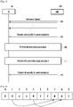
- FIG. 1 is a flow diagram of a method of transmitting a transmission power control parameter from a gNB 103, according to an example not falling in the scope of the invention.
- the gNB 103 may transmit cell-specific transmission power parameters at 107 which can be commonly used by all the cell-accessed UEs regardless of their capabilities.
- the gNB 103 can transmit P 0_PUSCH to the UE 101 for transmission power control of a physical uplink shared channel (PUSCH) and transmit P 0_PUCCH to the UE 101 for transmission power control of a physical uplink control channel (PUCCH).
- P 0_PUSCH is composed of a cell-specific parameter, P 0_NOMINAL_PUSCH , and a UE-specific parameter, P 0_UE_PUSCH .
- P 0_PUCCH is composed of a cell-specific parameter, P 0_NOMINAL_PUCCH , and a UE-specific parameter, P 0_UE_PUCCH .
- the cell-specific parameters P 0_NOMINAL_PUSCH and P 0_NOMINAL_PUCCH may be transmitted to the UE 101 through a channel, such as a master information block (MIB) or a system information block (SIB), broadcasted by the gNB.
- the UE-specific parameters P 0_UE_PUSCH and P 0_UE_PUCCH may be stored as a single default value in the UE 101 and the gNB in a state before the UE 101 accesses the gNB 103. The default value may be set to zero.
- the UE 101 capability may include a measurement parameter of the UE 101, handover, beam-related characteristics of the UE 101 (e.g., the reciprocity of transmission beam and reception beam, whether it is possible to select transmission beam(s) with reception beam(s) of the UE 101, and the like).
- beam-related characteristics of the UE 101 e.g., the reciprocity of transmission beam and reception beam, whether it is possible to select transmission beam(s) with reception beam(s) of the UE 101, and the like.
- the gNB 103 may provide one or more cell-specific configuration values via a broadcast channel such as the MIB or the SIB.
- the cell-specific configuration value may activate a gain for each beam type used in each of various downlink signals transmitted by the gNB 103, a difference between respective signals, a beam gain difference between the transmission beam and the reception beam, and the like.
- Such downlink signals transmitted by the gNB 103 in 105 may be a primary synchronization signal (PSS)/ secondary synchronization signal (SSS) for acquiring downlink synchronization of the UE 101, a cell-specific reference signal (CRS), and/or a demodulation reference signal (DMRS).
- PSS primary synchronization signal
- SSS secondary synchronization signal
- CRS cell-specific reference signal
- DMRS demodulation reference signal
- the UE 103 may continuously use the above-mentioned default values (P 0_UE_PUSCH and P 0_UE_PUCCH ) or the above-mentioned values activated by the gNB 103 (e.g., a gain for each beam type used in each of various downlink signals transmitted by the gNB 103, a difference between respective signals, a beam gain difference between the transmission beam and the reception beam) until there is an additional command from the gNB 103 as shown in FIG. 1 .
- P 0_UE_PUSCH and P 0_UE_PUCCH the above-mentioned values activated by the gNB 103
- the above-mentioned values activated by the gNB 103 e.g., a gain for each beam type used in each of various downlink signals transmitted by the gNB 103, a difference between respective signals, a beam gain difference between the transmission beam and the reception beam
- This additional command (update of values P 0_UE_PUSCH and P 0_UE_PUCCH ) of the gNB 103 may be provided through UE-specific RRC signaling or L1-signaling (PDCCH) after an RRC connection setup procedure at 111 or a random access procedure at 109 is performed.
- PDCH L1-signaling
- a single P 0_PUSCH and P 0_PUCCH value may be used without a distinction between cell-specific and UE-specific parameters. This value may be transmitted to the respective UEs via UE-specific RRC signaling dedicated to each UE or transmitted to the UEs in a cell-specific manner.
- the transmission power of the PUSCH in the i-th transmission unit, P PUSCH (i), may be determined in Equation (1) as follows.
- the unit is dBm.
- P PUSCH i min P CMAX i , 10 log 10 M PUSCH i + P 0 PUSCH j + ⁇ PUSCH j ⁇ PL + f i + ⁇ TF i dBm
- the parameter f(i) used in the i-th transmission unit may be obtained as follows. That is, f(i) may be obtained by accumulating a value transmitted by the gNB 103 to f(i-1) or by applying the value transmitted by the gNB 103 as it is. Whether such accumulation is enabled or disabled is determined by higher layer signaling of the gNB 103. Detailed operations are as follows.
- ⁇ PUSCH ( i - K PUSCH ) is a value signaled in the i-K PUSCH transmission unit.
- K PUSCH is fixed to 4 in the frequency division duplex (FDD) system
- K PUSCH is defined as shown in Table 1a below in the time division duplex (TDD) system.
- Table 1 K PUSCH Values in TDD System [Table 2] TDD UL/DL Configuration Subframe number i 0 1 2 3 4 5 6 7 8 9 0 4 6 4 6 1 6 6 6 4 2 4 4 3 4 4 4 4 4 5 4 6 7 7 7 5
- subframe numbers 2, 3, 7 and 8 denote uplink subframes
- subframe numbers 0, 1, 4, 5, 6 and 9 denote downlink subframes.
- an uplink of subframe number 2 indicates that uplink transmission information is acquired from a downlink before the sixth.
- This uplink transmission information also includes ⁇ PUSCH (i-K PUSCH ).
- ⁇ PUSCH (i-K PUSCH ) is defined in Table 3 as follows. [Table 3] TPC Command Field in DCI format 0/0A/0B/3/4/4A/4B/6-0A/3B Accumulated ⁇ PUSCH,c dB Absolute ⁇ PUSCH,c dB only DCI format 0/0A/0B/4/4A/4B/6-0A 0 -1 -4 1 0 -1 2 1 1 3 3 4
- a rule for transmission of a corresponding PUSCH after transmission of a PDCCH is defined as shown in Table 1b above.
- FIG. 2 is an illustration of a transmission relation between a downlink control channel and a corresponding uplink data channel according to an example not falling in the scope of the invention.
- the transmission of a corresponding uplink data channel after the reception of a downlink control channel is performed as shown in FIG. 2 .
- the transmission power necessary for the transmission of a corresponding data channel is calculated from Equation (1) above.
- the closed loop parameter used by the UE 101 in each transmission unit is operated according to the signaling of the gNB 103 and operated by applying the commands of the gNB 103. That is, the closed loop parameter f(i) of the UE 101 may be operated as expected by the gNB 103.
- Table 4 below is an example of DCI information transmission and closed parameter update of UE/eNB.
- Subframe Index 0 1 2 3 4 5 6 7 8 9 DCI Info K PUSCH - - 6 4 - - - 6 4 - ⁇ PUSCH (i) - 3 - - 1 - 0 - - 3 UE f(i) 0 0 0 0 0 0 3 4 4 eNB expected f(i) 0 0 0 0 0 0 0 3 4 4
- the method of operating the closed loop parameter for LTE power control is applied to a system in which the allocation of the uplink data channel is performed dynamically in the downlink control channel, a UE operation different from the expectation of the eNB may be caused.
- the dynamic allocation indicates that a time between the transmission of uplink allocation information (grant) on the PDCCH and the transmission of the PUSCH can be dynamically determined.
- information called K1 is introduced in the DCI of the PDCCH and is transmitted to the UE through the DCI.
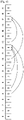
- FIG. 3 is an illustration of a transmission relation between a downlink control channel and a corresponding uplink data channel according to an embodiment.
- the reason is that new uplink allocation and uplink data transmission are performed before the eNB transmits uplink allocation information and the UE transmits corresponding uplink data.
- Table 5 below is an example of DCI information transmission and closed parameter update of UE/eNB.
- Subframe Index 0 1 2 3 4 5 6 7 8 9 DCI Info K1 - 7 - - 3 - - - - - ⁇ PUSCH (i) - 3 - - 3 - - - - - UE f(i) 0 0 0 0 0 0 0 3 6 6 eNB expected f e (i) 0 0 0 0 0 0 0 1 0 3
- K1 In addition to the case of directly transmitting information such as K1 to the DCI, there may be scenarios of defining various K1s according to services. Such examples are a system where ultra-reliable low latency communication (URLLC) and enhanced mobile broadband (eMBB) coexist, a case where the transmission unit size varies (slot vs. mini-slot), and the like.
- URLLC ultra-reliable low latency communication
- eMBB enhanced mobile broadband
- FIG. 4 is an illustration of a transmission relation between a downlink control channel and a corresponding uplink data channel according to an embodiment.
- FIG. 4 an example is shown of a transmission relation between the downlink control channel and the corresponding uplink data channel when K1 of the eMBB service is 5 and K1 of the URLLC service is 0. Even in case of transmitting the service type of uplink data rather than transmitting the K1 value directly with the DCI, the same problem occurs.
- Table 6 below is an example of DCI information transmission and closed parameter update of UE/eNB.
- the above issue is that the closed loop parameter used in calculating the power for transmitting the uplink data in the i-th transmission unit is different from the value expected by the eNB.
- the present disclosure addresses an issue that arises in case of accumulating closed loop parameters, as follows.
- the first embodiment is to update the closed loop parameter f(i) at the transmission time point (i) of uplink data by using the closed loop parameter f(i-K1) and the TPC command ⁇ PUSCH (i-K1) at the point in time (i-K1) when the eNB transmits grant information to instruct the transmission of uplink data.
- This embodiment allows the operation not affected in calculation of f(i) even though there are new resource allocation and corresponding uplink data transmission between transmission units i and i-K1. Thus, it can be applied as expected by the eNB (refer to FIG. 3 ).
- Table 7 is an example of DCI information transmission and closed parameter update of UE/eNB.
- Subframe Index 0 1 2 3 4 5 6 7 8 9 DCI Info K1 - 7 - - 3 - - - - - ⁇ PUSCH (i) - 1 - - 3 - - - - - UE f(i) 0 0 0 0 0 0 0 3 1 1 eNB expected f e (i) 0 0 0 0 0 0 0 0 3 1 1
- the second embodiment is to apply the previous f(i-1) without updating f(i) at the transmission point in time (i) of uplink data when there are new grant and uplink data transmission between the uplink data transmission point in time (i) and the point in time (i-K1) when the eNB transmits grant information to instruct the transmission of uplink data. Even though f(i) in the 8th transmission unit is different from the expected result of the eNB, it is possible to obtain the effect of applying the latest information to f(i).
- Table 8 below is an example of DCI information transmission and closed parameter update of UE/eNB.
- Subframe Index 0 1 2 3 4 5 6 7 8 9 DCI Info K1 - 7 - - 3 - - - - - ⁇ PUSCH (i) - 1 - - 3 - - - - - UE f(i) 0 0 0 0 0 0 0 3 3 3 eNB expected f e (i) 0 0 0 0 0 0 0 3 1 3
- the third embodiment is to use, but not store, f(i) updated by applying TPC command transmitted by the eNB when there are new grant and uplink data transmission between the uplink data transmission time point (i) and the time point (i-K1) when the eNB transmits grant information to instruct the transmission of uplink data. That is, f(i) used in the next transmission unit maintains a value before updated (refer to FIG. 3 ).
- Table 9 is an example of DCI information transmission and closed parameter update of UE/eNB.
- Subframe Index 0 1 2 3 4 5 6 7 8 9 DCI Info K1 - 7 - - 3 - - - - - ⁇ PUSCH (i) - 1 - - 3 - - - - - UE f(i) 0 0 0 0 0 0 0 3 1 1 eNB expected f e (i) 0 0 0 0 0 0 0 0 3 1 1
- the fourth embodiment is to operate f(i) by using a value before a certain time (T a ) after a certain time (T p ) based on a point in time (i-T p ) at which the eNB transmits a transmit power control (TPC) command.
- T a is 1 and T p is 3 (refer to FIG. 3 ).
- Table 10 below is an example of DCI information transmission and closed parameter update of UE/eNB.
- Subframe Index 0 1 2 3 4 5 6 7 8 9 DCI Info K1 - 7 - - 3 - - - - - ⁇ PUSCH (i) - 1 - - 3 - - - - - UE f(i) 0 0 0 0 1 1 1 4 4 4 4 eNB expected f e (i) 0 0 0 0 1 1 1 4 4 4 4 4
- a field indicating how to apply and manage a TPC command is added to the DCI.
- a TPC command usage field indicates how the UE applies a TPC command transmitted by the eNB. If the TPC command usage field is "0,” the current TPC command is accumulated, and such accumulation is used to calculate the power for uplink data transmission and stored as the closed loop parameter. If the TPC command usage field is "1," the current TPC command is accumulated and used for power calculation of uplink data transmission, but the closed loop parameter stores a value before accumulation. If the TPC command usage field is "2,” such accumulation is not performed, and the transmission power is calculated and stored using the current closed loop parameter.
- TPC Command Field in DCI format Accumulated ⁇ PUSCH,c dB Absolute ⁇ PUSCH,c dB 0 -1 -4 1 0 -1 2 1 1 3 3 4
- Table 12 below is an example of TPC Command Usage Field.
- TPC Command Usage Field in DCI format Accumulation for TPC Command Closed loop parameter after Accumulation action 0 Yes Use for transmit power calculation and store accumulated value 1 Yes Use for transmit power calculation and discard accumulated value 2 No Use for transmit power calculation and store accumulated value 3 Reserved Reserved
- the sixth embodiment is to operate f(i) with various values according to a beam, a beam group, a beam combination, a service type (eMBB, URLLC, etc.), a waveform (cyclic prefix orthogonal frequency division multiplexing (CP-OFDM), single carrier discrete Fourier transform SC-DFT, etc.), or subcarrier spacing (15kHz, 30kHz, 60kHz, etc.).
- a beam group e.g., URLLC, etc.
- a beam combination eMBB, URLLC, etc.
- a service type eMBB, URLLC, etc.
- CP-OFDM cyclic prefix orthogonal frequency division multiplexing
- SC-DFT single carrier discrete Fourier transform
- FIG. 5 is an illustration a transmission relation between a downlink control channel and a corresponding uplink data channel according to an example not falling in the scope of the invention.
- each of different transmission units when each of different transmission units sends K1 to designate the transmission unit for the transmission of uplink data, it may happen that a plurality of uplink data channels are scheduled to be transmitted in the same transmission unit.
- Table 13 below is an example of DCI information transmission and closed parameter update of UE/eNB.
- Subframe Index 0 1 2 3 4 5 6 7 8 9 DCI Info M (RB number) - 4 - - 1 - - - - - K1 - 6 - - 3 - - - - - ⁇ PUSCH (i) - 3 - - 1 - - - - - UE f(i) 0 0 0 0 0 0 3 or 1 3 or 1 3 or 1 eNB expected f e (i) 0 0 0 0 0 0 0 3 or 1 3 or 1 3 or 1 3 or 1 eNB expected f e (i) 0 0 0 0 0 0 0 3 or 1 3 or 1 3 or 1 3 or 1
- the present disclosure addresses the above issue, as follows.
- the above issue is caused by the existence of a plurality of closed loop parameters used in calculation of power for transmitting data of a plurality of uplinks in the i-th transmission unit.
- the first example is that the UE applies a common closed loop parameter when there are two or more uplink data channels in the i-th transmission unit.
- the common closed loop parameter may be defined as follows.
- the TPC command offered for the transmission of data having the largest data amount (or resource amount, modulation order, etc.) among uplink data transmitted in the i-th transmission unit is used as the closed loop parameter of the i-th transmission unit.
- the second example is that, when there are two or more uplink data channels in the i-th transmission unit, the UE updates the closed loop parameter and calculates the transmission power by applying the TPC command corresponding to each uplink data channel.
- one closed loop parameter is determined.
- a determination rule is as follows. The most recently received TPC command based on the i-th transmission unit is determined as a representative closed loop parameter of the i-th transmission unit. In the above example, 3 is selected as K1 from 3 and 7 in the 7th transmission unit, and the corresponding TPC command is applied to the calculation of the closed loop parameter.
- the representative closed loop parameter may be determined using a value used for the data channel having the largest resource amount among data channels of uplink in the i-th transmission unit, the largest TPC command value, or the like.
- the transmission power of the PUCCH in the i-th transmission unit, P PUCCH (i), may be determined as follows in Equation (2).
- the unit is dBm.
- P PUCCH i min P CMAX i , P 0 PUCCH j + PL + h n CQI n HARQ , n SR + ⁇ F _ PUCCH F + ⁇ TxD F ′ + g i dBm
- ⁇ PUCCH (i-k m ) is a value signaled in the i-k m transmission unit.
- FIG. 6 is an illustration of a transmission relation between a downlink control/data channel and a corresponding uplink HARQ-ACK channel according to an example not falling in the scope of the invention.
- a rule for the transmission of downlink data (PDSCH) and hybrid automatic repeat request acknowledgement (HARQ-ACK) after the transmission of a PDCCH is defined as shown in Table 14 above.
- the UE receives the downlink control channel and the corresponding downlink data channel and then transmits the HARQ-ACK to inform whether such channels are received successfully, as shown in FIG. 6 .
- the transmission power necessary for such data channel transmission is calculated using Equation (2) above.
- the closed loop parameter used by the UE in each transmission unit may be obtained as follows.
- the eNB may estimate the closed loop parameters used by the UE.
- a downlink assignment index (DAI) is an index transmitted to prevent an error of the HARQ-ACK in HARQ-ACK bundling of the PDSCH transmitted simultaneously in the next PUCCH transmission.
- Table 15 below is an example of DCI information transmission and closed parameter update of UE/eNB.
- the dynamic allocation indicates that a time between the transmission of downlink allocation information (grant) and the transmission of the HARQ-ACK can be dynamically determined.
- K0 A time between downlink control channel transmission and downlink data channel transmission
- K2 a time between downlink data channel transmission and corresponding HARQ-ACK transmission
- FIG. 7 is an illustration of a transmission relation between a downlink control/data channel and a corresponding uplink HARQ-ACK channel according to an example not falling in the scope of the invention.
- the HARQ-ACK is transmitted in response to three PDSCHs.
- the reason is that new downlink allocation and uplink HARQ-ACK transmission are performed before the eNB transmits downlink data and the UE transmits corresponding HARQ-ACK.
- Table 16 below is an example of DCI information transmission and closed parameter update of UE/eNB.
- Subframe Index 0 1 2 3 4 5 6 7 8 9 DCI K0 1 1 1 1 - - 1 - - - - Info K2 8 7 6 - - 1 - - - - DAI 0 1 2 - - 0 - - - - ⁇ PUCCH (i) 1 1 1 - - 3 - - - - UE g(i) 0 0 0 0 0 0 0 3 3 6 eNB expected g e (i) 0 0 0 0 0 0 0 3 3 3 3 3
- K0 and K2 In addition to case of directly introducing information such as K0 and K2 to the DCI, there may be scenarios having various K0s and K2s according to services. Such examples are a system where URLLC and eMBB coexist, a case where the transmission unit size varies (slot vs. mini-slot), and the like.
- FIG. 8 is an illustration of a transmission relation between a downlink control/data channel and a corresponding uplink HARQ-ACK channel according to an example not falling in the scope of the invention.
- Table 17 below is an example of DCI information transmission and closed parameter update of UE/eNB.
- the above issue is that the closed loop parameter used in calculating the power for transmitting the uplink HARQ-ACK in the i-th transmission unit is different from the value expected by the eNB.
- the present disclosure addresses an issue that arises in case of accumulating closed loop parameters, as follows.
- the first example is to update the closed loop parameter g(i) at the transmission point in time (i) of uplink HARQ-ACK by using the closed loop parameter g(i-K0-K2) and the TPC command ⁇ PUCCH (i) at the time point (i-K0-K2) when the eNB transmits grant information to instruct the transmission of uplink HARQ-ACK.
- a reference g(i-K0-K2) is based on the largest or arbitrary K0+K2.
- Table 18 below is an example of DCI information transmission and closed parameter update of UE/eNB.
- Subframe Index 0 1 2 3 4 5 6 7 8 9 DCI Info K0 1 1 1 1 - - 1 - - - - K2 8 7 6 - - 1 - - - - DAI 0 1 2 - - 0 - - - - ⁇ PUCCH (i) 1 1 1 - - 3 - - - - UE g(i) 0 0 0 0 0 0 0 3 3 3 3 eNB expected g e (i) 0 0 0 0 0 0 0 3 3 3 3
- the second example is to apply the previous g(i-1) without updating g(i) at the transmission point in time (i) of uplink HARQ-ACK when there are new grant and uplink HARQ-ACK transmission between the uplink HARQ-ACK transmission point in time (i) and the point in time (i-K0-K2) when the eNB transmits grant information to instruct the transmission of uplink HARQ-ACK.
- the third example is to use, but not store, g(i) updated by applying TPC command transmitted by the eNB when there are new grant and uplink HARQ-ACK transmission between the uplink HARQ-ACK transmission time point (i) and the point in time (i-K0-K2) when the eNB transmits grant information to instruct the transmission of uplink HARQ-ACK. That is, g(i) used in the next transmission unit maintains a value before updated.
- Table 19 below is an example of DCI information transmission and closed parameter update of UE/eNB.
- Subframe Index 0 1 2 3 4 5 6 7 8 9 DCI Info K0 1 1 1 1 - - 1 - - - - K2 8 7 6 - - 1 - - - - DAI 0 1 2 - - 0 - - - - ⁇ PUCCH (i) 1 1 1 - - 3 - - - - UE g(i) 0 0 0 0 0 0 0 3 0 3 eNB expected g e (i) 0 0 0 0 0 0 0 0 3 0 3
- a field indicating how to apply and manage a TPC command is added to the DCI.
- a TPC command usage field indicates how the UE applies a TPC command transmitted by the eNB. If the TPC command usage field is "0,” the current TPC command is accumulated, and such accumulation is used to calculate the power for uplink data transmission and stored as the closed loop parameter. If the TPC command usage field is "1," the current TPC command is accumulated and used for power calculation of uplink data transmission, but the closed loop parameter stores a value before accumulation. If the TPC command usage field is "2,” such accumulation is not performed, and the transmission power is calculated and stored using the current closed loop parameter.
- the fifth example is to operate g(i) with various values according to a beam, a beam group, a beam combination, a service type (eMBB, URLLC, etc.), a waveform (CP-OFDM, SC-DFT, etc.), or subcarrier spacing (15kHz, 30kHz, 60kHz, etc.).
- a beam group eMBB, URLLC, etc.
- a beam combination eMBB, URLLC, etc.
- subcarrier spacing 15kHz, 30kHz, 60kHz, etc.
- the LTE power control method is applied to a system using beamforming, the following issue may arise. Since path losses are different according to beam combinations, the eNB may not be able to achieve the desired reception power when ignoring a beam combination and applying a common path loss to the transmission power of uplink. Therefore, in the beamforming system, it is required to estimate and apply an appropriate path loss according to the UE transmission beam and the eNB reception beam. Assuming that the appropriate path loss is applied according to beam combinations, the transmission power P PUSCH,k (i) of PUSCH of the k-th beam in the i-th transmission unit may be determined as follows. The unit is dBm.
- the transmission power of the beamforming system may be operated using Equation (3) as follows.
- P PUSCH , k i min P CMAX i , 10 log 10 M PUSCH i + P 0 PUSCH , k j + ⁇ PUSCH , k j ⁇ PL k + f k i + ⁇ TF i dBm
- parameters such as P 0 PUSCH,k (j), ⁇ PUSCH,k (j), PL k , and f k (i) may be managed for each beam or beam combination or managed as a common value.
- the closed loop parameter f k (i) may have the following problem. Unlike the open loop parameter, the closed loop parameter performs a function of reducing an error by continuously feed-backing and updating a difference from a current state. In order to reduce an error of transmission power by using the closed loop parameter, continuous and periodic feedback of information is required.
- a new method for operating the closed loop parameter is as follows.
- the first example is an explicit operation method through the DCI.
- This directly signaling method may insert a reset in the TPC command field as shown in Table 20 below or add a TPC reset field in addition to the TPC command field as shown in Table 21 below.
- the TPC reset field is transmitted, the previous f k (i) is used or the f k (i) is initialized to zero.
- TPC Command Field in DCI format Accumulated ⁇ PUSCH,c dB Absolute ⁇ PUSCH,c dB 0 -3 -4 1 1 -1 2 1 1 3 3 4
- TPC Reset Field in DCI format Accumulated ⁇ PUSCH,c dB Absolute ⁇ PUSCH,c dB 0
- FIG. 9 is a flowchart of a method according to an example not falling in the scope of the invention.
- the UE receives an accumulation message from a higher layer at 901 and performs a certain operation of a closed loop parameter by using a TPC command field and a TPC reset field which are transmitted through DCI.
- an accumulation state is determined.
- a TPC command field and a TPC reset field are received.
- a TPC command field and a TPC reset field are received.
- the second example is an implicit operation method through higher layer signaling.
- This method allows the UE to initialize the closed loop parameter when a beam change occurs between the eNB and the UE.
- the higher layer signaling is defined and used as follows: accumulation enabled, accumulation enabled with beam change condition 1, accumulation enabled with beam change condition 2, and accumulation disabled.
- the accumulation enabled allows the UE to accumulate the closed loop parameter by using the TPC command of the DCI regardless of a beam change between the eNB and the UE.
- the accumulation enabled with beam change condition 1 allows the UE to initialize the closed loop parameter even if there is the TPC command of the DCI when a change occurs in a UE transmission beam.
- the accumulation enabled with beam change condition 2 allows the UE to initialize the closed loop parameter if a beam change between the eNB and the UE occurs by a command of the eNB.
- the accumulation disabled allows the UE to apply an absolute value by using the TPC command of the DCI regardless of a beam change between the eNB and the UE.
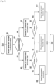
- FIG. 10 is a flowchart of a method according to an example not falling in the scope of the invention.
- the UE receives a higher layer message transmitted by the eNB in 1001.
- 1003 it is determined if accumulation is enabled.
- the UE receives a TPC command field and applies an absolute value by using a TPC command value in 1007.
- the accumulation is enabled in 1009, it is determined if there is a condition, where the operation is varied depending on whether there is a condition. If there is no condition in 1011, the UE receives a TPC command field and performs accumulation using a TPC command value in 1013.
- the UE receives a TPC command field in 1017 and checks whether a UE beam changes in 1019 (the eNB may not know the beam change). If the MS beam changes, the UE initializes the closed loop parameter in 1021, otherwise, the UE performs accumulation in 1013. In a case where there is an accumulation condition 2, the UE receives a TPC command field in 1023, determines if there is beam change information from a base station in 1025, initializes the closed loop parameter in 1021 only when the eNB explicitly changes a beam (the eNB knows the beam change), and performs accumulation using a TPC command value in 1013 when there is no beam change information from the base station.
- the third example is to use both the explicit and implicit methods.
- the upper layer signaling is used to initialize the closed loop parameter when the UE recognizes the beam change as described in the implicit method, and also a field for initializing the closed loop parameter is applied to the TPC command of the DCI. That is, even though there is no beam change, the eNB can dynamically initialize the closed loop parameters of the UE.
- a plurality of transmission formats may exist depending on the amount of information to be transmitted, a generation method, or the like.
- Each transmission format uses an independent transmission power equation. For example, in case of the PUCCH of LTE, different equations are applied to format 1/1a/1b/2/2a/2b/3 and format 4/5, as follows.
- P PUCCH i min P Cmax i P 0 _ PUCCH + PL + h n CQI n HARQ n SR + ⁇ F PUCCH F + ⁇ T ⁇ D F ′ + g i dBm
- P PUCCH i min P Cmax i P 0 _ PUCCH + PL + 10 log 10 M PUCCH i + ⁇ F PUCCH F + ⁇ TF i + g i
- LTE there may be a plurality of schemes of power calculation for transmission of the uplink control channel in a new system (e.g., a new radio access technology (RAT)).
- RAT new radio access technology
- the closed loop parameter used in each power control may be operated as follows.
- the uplink control channel has a control channel of transmitting a small amount of information and a control channel of transmitting a large amount of information.
- the control channel that transmits a small amount of information reflects the concept of bundling. That is, each of HACK-ACK/non-acknowledgement (NACK) for a plurality of downlink data channels is determined as one HACK-ACK/NACK bit through an AND logical operation. Therefore, one bit is very important, and the closed loop parameter transmitted through the PDCCH allocating downlink data transmission is accumulated.
- the uplink control channel that transmits a large amount of information is transmitted by multiplexing HACK-ACK/NACK for all data channels received on the downlink. Because the importance of an information bit transmitted in the uplink control channel may vary, there may be no need to use the closed loop parameters of other formats. Therefore, the eNB may operate the closed loop parameter applied to each PUCCH format in various types as follows.
- a frequency hopping pattern of the uplink control channel transmitted by the UE may be signaled by the eNB or performed by the UE in a promised manner. Then, the reception performance of the control channel may vary depending on the hopping pattern or whether hopping is made at the transmission of the uplink control channel. In this case where the performance of the uplink control channel varies, adjusting the transmission power according to the reception performance may reduce the power consumption of the UE and also reduce the interference amount to the neighbor eNB.
- ⁇ FH (H) is applied to a PUCCH transmission power calculation equation.
- the LTE PUCCH transmission power calculation equation is used as an example in this disclosure, the same may be applied equally to other transmission power as in Equation (6) as follows.
- P PUCCH i min P Cmax i P 0 _ PUCCH + PL + h n CQI n HARQ n SR + ⁇ F PUCCH F + ⁇ FH H + ⁇ T ⁇ D F ′ + g i dBm
- ⁇ FH (H) is a value depending on frequency hopping or not and a frequency hopping pattern.
- ⁇ FH (H) One method of applying ⁇ FH (H) is to signal ⁇ FH (H) from a higher layer. This value is transmitted as a relative or absolute value for each hopping pattern based on a certain hopping pattern. Another method is to define and apply a value according to a frequency hopping pattern. The frequency hopping value may be determined based on the performance by the frequency hopping pattern, and may also relate to a bandwidth part, a carrier frequency, a waveform, and the like of the UE.
- the eNB determines and operates relative values based on a certain hopping pattern as shown in Table 22 below.
- Table 22 Type Value Non-Hopping -1 Hopping pattern 1 0 Hopping pattern 2 1 ⁇ ⁇
- the eNB operates values by further considering the BWP of the UE as shown below in Table 23.
- Table 23 below may be wholly informed to the UE, but the UE may transmit only the corresponding BWP value.
- a performance difference by the center frequency or waveform may be operated in the same way.
- BWP #1 Value Non-Hopping -1 Hopping pattern 1 0 Hopping pattern 2 1 ⁇ ⁇ ⁇ BWP #2 Value Non-Hopping -0.5 Hopping pattern 1 0 Hopping pattern 2 0.5 ⁇ ⁇ ⁇ BWP #N Value Non-Hopping -2 Hopping pattern 1 0 Hopping pattern 2 2 ⁇ ⁇
- control channel resources may be allocated contiguously or non-contiguously.
- the reception performance of the uplink control channel may vary. In case where the performance of the uplink control channel varies, adjusting the transmission power according to the reception performance can reduce the power consumption of the UE and reduce the interference amount to the neighbor eNB.
- ⁇ RA (A) is applied to a PUCCH transmission power calculation equation.
- the LTE PUCCH transmission power calculation equation is used as an example in this disclosure, the same may be applied equally to other transmission power.
- P PUCCH i min P Cmax i P 0 _ PUCCH + PL + h n CQI n HARQ n SR + ⁇ F PUCCH F + ⁇ RA A + ⁇ T ⁇ D F ′ + g i dBm
- ⁇ RA (A) is a value depending on the type of PUCCH resource allocation.
- ⁇ RA (A) One method of applying ⁇ RA (A) is to signal ⁇ RA (A) from a higher layer. This value is transmitted as a relative or absolute value for each resource allocation type based on a certain resource allocation type. Another method is to define and apply a value according to a resource allocation type.
- the eNB determines and operates relative values based on a certain allocation type as shown in Table 24 below. Although the contiguous allocation is used as a reference, any other allocation type may be used alternatively.
- Table 24 Type Value Contiguous Allocation 0 Non-contiguous Allocation 1 0.5 Non-contiguous Allocation 2 1 ⁇ ⁇
- FIG. 11 is a block diagram of a terminal 1100 according to an embodiment.
- the terminal 1100 may include a transceiver 1110, a controller 1120, and storage 1130.
- the controller 1120 may be defined as a circuit, an application-specific integrated circuit (ASIC), or at least one processor.
- the transceiver 1110 may transmit and receive signals to and from other network entities.
- the transceiver 1110 may receive system information, a synchronization signal, or a reference signal from a base station.
- the controller 1120 may control the overall operation of the terminal 1100 according to embodiments of the present disclosure.
- the controller 1120 may control a signal flow between blocks to perform the above-described operation.
- the storage 1130 may store at least one of information transmitted or received through the transceiver 1110 and information generated through the controller 1120.
- FIG. 12 is a block diagram of a base station 1200 according to an embodiment.
- the base station 1200 may include a transceiver 1210, a controller 1220, and storage 1230.
- the controller 1220 may be defined as an ASIC, or at least one processor.
- the transceiver 1210 may transmit and receive signals to and from other network entities.
- the transceiver 1210 may transmit system information, a synchronization signal, or a reference signal to a terminal.
- the controller 1220 may control the overall operation of the base station 1200 according to an embodiment.
- the controller 1220 may control a signal flow between blocks to perform the above-described operation.
- the storage 1230 may store at least one of information transmitted or received through the transceiver 1210 and information generated through the controller 1220.
Landscapes
- Engineering & Computer Science (AREA)
- Computer Networks & Wireless Communication (AREA)
- Signal Processing (AREA)
- Mobile Radio Communication Systems (AREA)
Claims (15)
- Verfahren zum Übertragen von Daten, das von einem Endgerät (101) in einem mobilen Kommunikationssystem ausgeführt wird, wobei das Verfahren Folgendes umfasst:Empfangen erster Steuerungsinformationen zu einem ersten Zeitpunkt von einer Basisstation (103), wobei die ersten Steuerungsinformationen das Endgerät anweisen, erste Uplink-Daten zu einem vierten Zeitpunkt zu übertragen;Empfangen zweiter Steuerungsinformationen zu einem zweiten Zeitpunkt nach dem ersten Zeitpunkt von der Basisstation (103), wobei die zweiten Steuerungsinformationen das Endgerät anweisen, zweite Uplink-Daten zu einem dritten Zeitpunkt vor dem vierten Zeitpunkt zu übertragen;Übertragen der zweiten Uplink-Daten zu einem dritten Zeitpunkt an die Basisstation (103) basierend auf den zweiten Steuerungsinformationen;Bestimmen einer Übertragungsleistung der ersten Uplink-Daten entsprechend den ersten Steuerungsinformationen basierend auf einer Übertragungsleistung der zweiten Uplink-Daten.
- Verfahren nach Anspruch 1, wobei die Übertragungsleistung der ersten Uplink-Daten basierend auf der Übertragungsleistung der zweiten Uplink-Daten und einem Leistungsparameter zum Übertragen der ersten Uplink-Daten bestimmt wird, die in den ersten Steuerungsinformationen enthalten sind.
- Verfahren nach Anspruch 1, wobei das Bestimmen der Übertragungsleistung der ersten Uplink-Daten Folgendes umfasst:Identifizieren einer verstrichenen Zeit nach der Übertragung der zweiten Uplink-Daten;Bestimmen der Übertragungsleistung der ersten Uplink-Daten basierend auf der Übertragungsleistung der zweiten Uplink-Daten und einem Leistungsparameter zum Übertragen der ersten Uplink-Daten, die in den ersten Steuerungsinformationen enthalten sind, falls die verstrichene Zeit kleiner als eine vorbestimmte Schwelle ist; undBestimmen der Übertragungsleistung der ersten Uplink-Daten basierend auf der Übertragungsleistung der zweiten Uplink-Daten, falls die verstrichene Zeit größer als oder gleich der vorbestimmten Schwelle ist.
- Verfahren nach Anspruch 1, welches ferner Folgendes umfasst:
Empfangen von Informationen über einen Leistungsparameter zum Bestimmen der Übertragungsleistung der ersten Uplink-Daten von der Basisstation. - Verfahren zum Empfangen von Daten, welches von einer Basisstation (103) in einem mobilen Kommunikationssystem ausgeführt wird, wobei das Verfahren Folgendes umfasst:Übertragen erster Steuerungsinformationen zu einem ersten Zeitpunkt an ein Endgerät (101), wobei die ersten Steuerungsinformationen das Endgerät anweisen, erste Uplink-Daten zu einem vierten Zeitpunkt zu übertragen;Übertragen zweiter Steuerungsinformationen zu einem zweiten Zeitpunkt nach dem ersten Zeitpunkt an das Endgerät (101), wobei die zweiten Steuerungsinformationen das Endgerät anweisen, zweite Uplink-Daten zu einem dritten Zeitpunkt vor dem vierten Zeitpunkt zu übertragen;Empfangen der zweiten Uplink-Daten zu einem dritten Zeitpunkt von dem Endgerät (101) basierend auf den zweiten Steuerungsinformationen;Bestimmen einer Übertragungsleistung der ersten Uplink-Daten, die von dem Endgerät übertragen werden, basierend auf einer Übertragungsleistung der zweiten Uplink-Daten, die von dem Endgerät übertragen werden.
- Verfahren nach Anspruch 5, wobei die Übertragungsleistung der ersten Uplink-Daten, die von dem Endgerät übertragen werden, basierend auf der Übertragungsleistung der zweiten Uplink-Daten, die von dem Endgerät übertragen werden, und einem Leistungsparameter zum Empfangen der ersten Uplink-Daten bestimmt wird, die in den ersten Steuerungsinformationen enthalten sind.
- Verfahren nach Anspruch 5, wobei das Bestimmen der Übertragungsleistung der ersten Uplink-Daten, die von dem Endgerät übertragen werden, Folgendes umfasst:Identifizieren einer verstrichenen Zeit nach dem Empfangen der zweiten Uplink-Daten;Bestimmen der Übertragungsleistung der ersten Uplink-Daten, die von dem Endgerät übertragen werden, basierend auf der Übertragungsleistung der zweiten Uplink-Daten, die von dem Endgerät übertragen werden, und einem Leistungsparameter zum Empfangen der ersten Uplink-Daten, die in den ersten Steuerungsinformationen enthalten sind, falls die verstrichene Zeit kleiner als eine vorbestimmte Schwelle ist; undBestimmen der Übertragungsleistung der ersten Uplink-Daten, die von dem Endgerät übertragen werden, basierend auf der Übertragungsleistung der zweiten Uplink-Daten, die von dem Endgerät übertragen werden, falls die verstrichene Zeit größer als oder gleich der vorbestimmten Schwelle ist.
- Verfahren nach Anspruch 5, welches ferner Folgendes umfasst:
Übertragen von Informationen über einen Leistungsparameter an das Endgerät zum Bestimmen der Übertragungsleistung der ersten Uplink-Daten, die von dem Endgerät übertragen werden. - Endgerät (101) in einem mobilen Kommunikationssystem, wobei das Endgerät Folgendes umfasst:einen Transceiver (1110); undeine Steuerung (1120), die konfiguriert ist zum:Empfangen erster Steuerungsinformationen zu einem ersten Zeitpunkt von einer Basisstation (103) über den Transceiver (1110), wobei die ersten Steuerungsinformationen das Endgerät anweisen, erste Uplink-Daten zu einem vierten Zeitpunkt zu übertragen,Empfangen zweiter Steuerungsinformationen zu einem zweiten Zeitpunkt nach dem ersten Zeitpunkt von der Basisstation (103) über den Transceiver (1110), wobei die zweiten Steuerungsinformationen das Endgerät anweisen, zweite Uplink-Daten zu einem dritten Zeitpunkt vor dem vierten Zeitpunkt zu übertragen,Übertragen der zweiten Uplink-Daten zu einem dritten Zeitpunkt an die Basisstation (103) über den Transceiver (1110) basierend auf den zweiten Steuerungsinformationen, undBestimmen einer Übertragungsleistung der ersten Uplink-Daten entsprechend den ersten Steuerungsinformationen basierend auf einer Übertragungsleistung der zweiten Uplink-Daten.
- Endgerät nach Anspruch 9, wobei die Steuerung ferner konfiguriert ist, um die Übertragungsleistung der ersten Uplink-Daten zu bestimmen, basierend auf der Übertragungsleistung der zweiten Uplink-Daten und einem Leistungsparameter zum Übertragen der ersten Uplink-Daten, die in den ersten Steuerungsinformationen enthalten sind.
- Endgerät nach Anspruch 9, wobei die Steuerung ferner konfiguriert ist zum:Identifizieren einer verstrichenen Zeit nach der Übertragung der zweiten Uplink-Daten,Bestimmen der Übertragungsleistung der ersten Uplink-Daten basierend auf der Übertragungsleistung der zweiten Uplink-Daten und einem Leistungsparameter zum Übertragen der ersten Uplink-Daten, die in den ersten Steuerungsinformationen enthalten sind, falls die verstrichene Zeit kleiner als eine vorbestimmte Schwelle ist, undBestimmen der Übertragungsleistung der ersten Uplink-Daten basierend auf der Übertragungsleistung der zweiten Uplink-Daten, falls die verstrichene Zeit größer als oder gleich der vorbestimmten Schwelle ist.
- Endgerät nach Anspruch 9, wobei die Steuerung ferner konfiguriert ist, um den Transceiver zum Empfangen von Informationen von der Basisstation über einen Leistungsparameter zum Bestimmen der Übertragungsleistung der ersten Uplink-Daten zu steuern.
- Basisstation (103) in einem mobilen Kommunikationssystem, wobei die Basisstation Folgendes umfasst:einen Transceiver (1210); undeine Steuerung (1220), die konfiguriert ist zum:Übertragen erster Steuerungsinformationen zu einem ersten Zeitpunkt an ein Endgerät (101) über den Transceiver (1210), wobei die ersten Steuerungsinformationen das Endgerät anweisen, erste Uplink-Daten zu einem vierten Zeitpunkt zu übertragen,Übertragen zweiter Steuerungsinformationen zu einem zweiten Zeitpunkt nach dem ersten Zeitpunkt an das Endgerät (101) über den Transceiver (1210), wobei die zweiten Steuerungsinformationen das Endgerät anweisen, zweite Uplink-Daten zu einem dritten Zeitpunkt vor dem vierten Zeitpunkt zu übertragen,Empfangen der zweiten Uplink-Daten zu einem dritten Zeitpunkt von dem Endgerät (101) über den Transceiver (1210) basierend auf den zweiten Steuerungsinformationen, undBestimmen einer Übertragungsleistung der ersten Uplink-Daten, die von dem Endgerät übertragen werden, basierend auf einer Übertragungsleistung der zweiten Uplink-Daten, die von dem Endgerät übertragen werden.
- Basisstation nach Anspruch 13, wobei die Steuerung ferner konfiguriert ist, um die Übertragungsleistung der ersten Uplink-Daten zu bestimmen, die von dem Endgerät übertragen werden, basierend auf der Übertragungsleistung der zweiten Uplink-Daten, die von dem Endgerät übertragen werden, und einem Leistungsparameter zum Empfangen der ersten Uplink-Daten, die in den ersten Steuerungsinformationen enthalten sind.
- Basisstation nach Anspruch 13, wobei die Steuerung ferner konfiguriert ist zum:Identifizieren einer verstrichenen Zeit nach dem Empfangen der zweiten Uplink-Daten,Bestimmen der Übertragungsleistung der ersten Uplink-Daten, die von dem Endgerät übertragen werden, basierend auf der Übertragungsleistung der zweiten Uplink-Daten, die von dem Endgerät übertragen werden, und einem Leistungsparameter zum Empfangen der ersten Uplink-Daten, die in den ersten Steuerungsinformationen enthalten sind, falls die verstrichene Zeit kleiner als eine vorbestimmte Schwelle ist, undBestimmen der Übertragungsleistung der ersten Uplink-Daten, die von dem Endgerät übertragen werden, basierend auf der Übertragungsleistung der zweiten Uplink-Daten, die von dem Endgerät übertragen werden, falls die verstrichene Zeit größer als oder gleich der vorbestimmten Schwelle ist.
Applications Claiming Priority (3)
| Application Number | Priority Date | Filing Date | Title |
|---|---|---|---|
| KR20170101956 | 2017-08-10 | ||
| KR1020170116110A KR102341474B1 (ko) | 2017-08-10 | 2017-09-11 | 빔포밍 시스템에서 단말의 송신 전력 제어 방법 및 장치 |
| PCT/KR2018/009117 WO2019031882A1 (en) | 2017-08-10 | 2018-08-09 | METHOD AND APPARATUS FOR CONTROLLING TRANSMISSION POWER OF TERMINAL IN MOBILE COMMUNICATION SYSTEM |
Publications (3)
| Publication Number | Publication Date |
|---|---|
| EP3652999A1 EP3652999A1 (de) | 2020-05-20 |
| EP3652999A4 EP3652999A4 (de) | 2020-07-08 |
| EP3652999B1 true EP3652999B1 (de) | 2023-02-22 |
Family
ID=65562040
Family Applications (1)
| Application Number | Title | Priority Date | Filing Date |
|---|---|---|---|
| EP18844059.8A Active EP3652999B1 (de) | 2017-08-10 | 2018-08-09 | Steuerung der übertragungsleistung eines endgeräts in einem mobilkommunikationssystem |
Country Status (2)
| Country | Link |
|---|---|
| EP (1) | EP3652999B1 (de) |
| KR (1) | KR102341474B1 (de) |
Families Citing this family (1)
| Publication number | Priority date | Publication date | Assignee | Title |
|---|---|---|---|---|
| CN112399539B (zh) * | 2019-08-16 | 2022-08-26 | 华为技术有限公司 | 功率控制方法和装置 |
Family Cites Families (3)
| Publication number | Priority date | Publication date | Assignee | Title |
|---|---|---|---|---|
| JP3429674B2 (ja) * | 1998-04-28 | 2003-07-22 | 沖電気工業株式会社 | 多重通信システム |
| US7693110B2 (en) | 2004-09-16 | 2010-04-06 | Motorola, Inc. | System and method for downlink signaling for high speed uplink packet access |
| WO2015109602A1 (en) | 2014-01-27 | 2015-07-30 | Panasonic Intellectual Property Corporation Of America | Wireless device and power control method |
-
2017
- 2017-09-11 KR KR1020170116110A patent/KR102341474B1/ko active IP Right Grant
-
2018
- 2018-08-09 EP EP18844059.8A patent/EP3652999B1/de active Active
Also Published As
| Publication number | Publication date |
|---|---|
| KR102341474B1 (ko) | 2021-12-22 |
| EP3652999A1 (de) | 2020-05-20 |
| KR20190017596A (ko) | 2019-02-20 |
| EP3652999A4 (de) | 2020-07-08 |
Similar Documents
| Publication | Publication Date | Title |
|---|---|---|
| US11523383B2 (en) | Method and device for setting plurality of DMRS structures in wireless cellular communication system | |
| US11683763B2 (en) | Method and device for controlling transmission power of terminal in wireless communication system | |
| US11147029B2 (en) | Method and device for controlling transmission power of terminal in beamforming system | |
| US11076387B2 (en) | Method and device for transmitting or receiving control information in wireless communication system | |
| US10462756B2 (en) | Method and apparatus for controlling transmission power of terminal in mobile communication system | |
| US11304155B2 (en) | Method and device for transmitting power headroom information in communication system | |
| KR20190017136A (ko) | 무선 통신 시스템에서 상향링크 전송 방법 및 장치 | |
| US20220104138A1 (en) | Method and apparatus for controlling transmission power of ue in wireless communication system | |
| EP4195846A1 (de) | Verfahren und vorrichtung zum senden und empfangen von uplink in einem drahtloskommunikationssystem | |
| US20230189250A1 (en) | Method and device for transmitting and receiving uplink in wireless communication system | |
| US20220086768A1 (en) | Method and device for controlling power in wireless communication system | |
| US11570729B2 (en) | Method and device for controlling transmission power of terminal in beamforming system | |
| US20220224456A1 (en) | Method and apparatus for transmitting uplink channel in wireless communication system | |
| CN113711526A (zh) | 在无线通信系统中收发上行链路参考信号的方法和设备 | |
| CN114762263A (zh) | 用于网络协作通信的默认波束配置方法及装置 | |
| EP3652999B1 (de) | Steuerung der übertragungsleistung eines endgeräts in einem mobilkommunikationssystem | |
| EP4135422A1 (de) | Verfahren und vorrichtung zur steuerung der übertragungsleistung eines endgeräts in einem drahtloskommunikationssystem | |
| EP4224769A1 (de) | Verfahren und vorrichtung zum senden und empfangen von uplink in einem drahtloskommunikationssystem | |
| CN117063542A (zh) | 无线通信系统中报告上行链路功率余量的方法和装置 | |
| CN116888917A (zh) | 用于在无线通信系统中发送上行链路信道的方法和装置 | |
| KR20220103002A (ko) | 무선 통신 시스템에서 상향링크 채널 송신 방법 및 장치 | |
| KR20180122239A (ko) | Dynamic TDD 시스템을 위한 전송 전력 제어 방안 |
Legal Events
| Date | Code | Title | Description |
|---|---|---|---|
| STAA | Information on the status of an ep patent application or granted ep patent |
Free format text: STATUS: THE INTERNATIONAL PUBLICATION HAS BEEN MADE |
|
| PUAI | Public reference made under article 153(3) epc to a published international application that has entered the european phase |
Free format text: ORIGINAL CODE: 0009012 |
|
| STAA | Information on the status of an ep patent application or granted ep patent |
Free format text: STATUS: REQUEST FOR EXAMINATION WAS MADE |
|
| 17P | Request for examination filed |
Effective date: 20200210 |
|
| AK | Designated contracting states |
Kind code of ref document: A1 Designated state(s): AL AT BE BG CH CY CZ DE DK EE ES FI FR GB GR HR HU IE IS IT LI LT LU LV MC MK MT NL NO PL PT RO RS SE SI SK SM TR |
|
| AX | Request for extension of the european patent |
Extension state: BA ME |
|
| REG | Reference to a national code |
Ref country code: DE Ref legal event code: R079 Ref document number: 602018046510 Country of ref document: DE Free format text: PREVIOUS MAIN CLASS: H04W0052540000 Ipc: H04W0052160000 |
|
| A4 | Supplementary search report drawn up and despatched |
Effective date: 20200609 |
|
| RIC1 | Information provided on ipc code assigned before grant |
Ipc: H04W 52/16 20090101AFI20200604BHEP |
|
| DAV | Request for validation of the european patent (deleted) | ||
| DAX | Request for extension of the european patent (deleted) | ||
| STAA | Information on the status of an ep patent application or granted ep patent |
Free format text: STATUS: EXAMINATION IS IN PROGRESS |
|
| 17Q | First examination report despatched |
Effective date: 20201130 |
|
| STAA | Information on the status of an ep patent application or granted ep patent |
Free format text: STATUS: EXAMINATION IS IN PROGRESS |
|
| GRAP | Despatch of communication of intention to grant a patent |
Free format text: ORIGINAL CODE: EPIDOSNIGR1 |
|
| STAA | Information on the status of an ep patent application or granted ep patent |
Free format text: STATUS: GRANT OF PATENT IS INTENDED |
|
| INTG | Intention to grant announced |
Effective date: 20220914 |
|
| GRAS | Grant fee paid |
Free format text: ORIGINAL CODE: EPIDOSNIGR3 |
|
| GRAA | (expected) grant |
Free format text: ORIGINAL CODE: 0009210 |
|
| STAA | Information on the status of an ep patent application or granted ep patent |
Free format text: STATUS: THE PATENT HAS BEEN GRANTED |
|
| AK | Designated contracting states |
Kind code of ref document: B1 Designated state(s): AL AT BE BG CH CY CZ DE DK EE ES FI FR GB GR HR HU IE IS IT LI LT LU LV MC MK MT NL NO PL PT RO RS SE SI SK SM TR |
|
| REG | Reference to a national code |
Ref country code: GB Ref legal event code: FG4D |
|
| REG | Reference to a national code |
Ref country code: CH Ref legal event code: EP |
|
| REG | Reference to a national code |
Ref country code: AT Ref legal event code: REF Ref document number: 1550305 Country of ref document: AT Kind code of ref document: T Effective date: 20230315 Ref country code: IE Ref legal event code: FG4D |
|
| REG | Reference to a national code |
Ref country code: DE Ref legal event code: R096 Ref document number: 602018046510 Country of ref document: DE |
|
| REG | Reference to a national code |
Ref country code: LT Ref legal event code: MG9D |
|
| REG | Reference to a national code |
Ref country code: NL Ref legal event code: MP Effective date: 20230222 |
|
| REG | Reference to a national code |
Ref country code: AT Ref legal event code: MK05 Ref document number: 1550305 Country of ref document: AT Kind code of ref document: T Effective date: 20230222 |
|
| PG25 | Lapsed in a contracting state [announced via postgrant information from national office to epo] |
Ref country code: RS Free format text: LAPSE BECAUSE OF FAILURE TO SUBMIT A TRANSLATION OF THE DESCRIPTION OR TO PAY THE FEE WITHIN THE PRESCRIBED TIME-LIMIT Effective date: 20230222 Ref country code: PT Free format text: LAPSE BECAUSE OF FAILURE TO SUBMIT A TRANSLATION OF THE DESCRIPTION OR TO PAY THE FEE WITHIN THE PRESCRIBED TIME-LIMIT Effective date: 20230622 Ref country code: NO Free format text: LAPSE BECAUSE OF FAILURE TO SUBMIT A TRANSLATION OF THE DESCRIPTION OR TO PAY THE FEE WITHIN THE PRESCRIBED TIME-LIMIT Effective date: 20230522 Ref country code: NL Free format text: LAPSE BECAUSE OF FAILURE TO SUBMIT A TRANSLATION OF THE DESCRIPTION OR TO PAY THE FEE WITHIN THE PRESCRIBED TIME-LIMIT Effective date: 20230222 Ref country code: LV Free format text: LAPSE BECAUSE OF FAILURE TO SUBMIT A TRANSLATION OF THE DESCRIPTION OR TO PAY THE FEE WITHIN THE PRESCRIBED TIME-LIMIT Effective date: 20230222 Ref country code: LT Free format text: LAPSE BECAUSE OF FAILURE TO SUBMIT A TRANSLATION OF THE DESCRIPTION OR TO PAY THE FEE WITHIN THE PRESCRIBED TIME-LIMIT Effective date: 20230222 Ref country code: HR Free format text: LAPSE BECAUSE OF FAILURE TO SUBMIT A TRANSLATION OF THE DESCRIPTION OR TO PAY THE FEE WITHIN THE PRESCRIBED TIME-LIMIT Effective date: 20230222 Ref country code: ES Free format text: LAPSE BECAUSE OF FAILURE TO SUBMIT A TRANSLATION OF THE DESCRIPTION OR TO PAY THE FEE WITHIN THE PRESCRIBED TIME-LIMIT Effective date: 20230222 Ref country code: AT Free format text: LAPSE BECAUSE OF FAILURE TO SUBMIT A TRANSLATION OF THE DESCRIPTION OR TO PAY THE FEE WITHIN THE PRESCRIBED TIME-LIMIT Effective date: 20230222 |
|
| PG25 | Lapsed in a contracting state [announced via postgrant information from national office to epo] |
Ref country code: SE Free format text: LAPSE BECAUSE OF FAILURE TO SUBMIT A TRANSLATION OF THE DESCRIPTION OR TO PAY THE FEE WITHIN THE PRESCRIBED TIME-LIMIT Effective date: 20230222 Ref country code: PL Free format text: LAPSE BECAUSE OF FAILURE TO SUBMIT A TRANSLATION OF THE DESCRIPTION OR TO PAY THE FEE WITHIN THE PRESCRIBED TIME-LIMIT Effective date: 20230222 Ref country code: IS Free format text: LAPSE BECAUSE OF FAILURE TO SUBMIT A TRANSLATION OF THE DESCRIPTION OR TO PAY THE FEE WITHIN THE PRESCRIBED TIME-LIMIT Effective date: 20230622 Ref country code: GR Free format text: LAPSE BECAUSE OF FAILURE TO SUBMIT A TRANSLATION OF THE DESCRIPTION OR TO PAY THE FEE WITHIN THE PRESCRIBED TIME-LIMIT Effective date: 20230523 Ref country code: FI Free format text: LAPSE BECAUSE OF FAILURE TO SUBMIT A TRANSLATION OF THE DESCRIPTION OR TO PAY THE FEE WITHIN THE PRESCRIBED TIME-LIMIT Effective date: 20230222 |
|
| PG25 | Lapsed in a contracting state [announced via postgrant information from national office to epo] |
Ref country code: SM Free format text: LAPSE BECAUSE OF FAILURE TO SUBMIT A TRANSLATION OF THE DESCRIPTION OR TO PAY THE FEE WITHIN THE PRESCRIBED TIME-LIMIT Effective date: 20230222 Ref country code: RO Free format text: LAPSE BECAUSE OF FAILURE TO SUBMIT A TRANSLATION OF THE DESCRIPTION OR TO PAY THE FEE WITHIN THE PRESCRIBED TIME-LIMIT Effective date: 20230222 Ref country code: EE Free format text: LAPSE BECAUSE OF FAILURE TO SUBMIT A TRANSLATION OF THE DESCRIPTION OR TO PAY THE FEE WITHIN THE PRESCRIBED TIME-LIMIT Effective date: 20230222 Ref country code: DK Free format text: LAPSE BECAUSE OF FAILURE TO SUBMIT A TRANSLATION OF THE DESCRIPTION OR TO PAY THE FEE WITHIN THE PRESCRIBED TIME-LIMIT Effective date: 20230222 Ref country code: CZ Free format text: LAPSE BECAUSE OF FAILURE TO SUBMIT A TRANSLATION OF THE DESCRIPTION OR TO PAY THE FEE WITHIN THE PRESCRIBED TIME-LIMIT Effective date: 20230222 |
|
| PGFP | Annual fee paid to national office [announced via postgrant information from national office to epo] |
Ref country code: GB Payment date: 20230720 Year of fee payment: 6 |
|
| REG | Reference to a national code |
Ref country code: DE Ref legal event code: R097 Ref document number: 602018046510 Country of ref document: DE |
|
| PG25 | Lapsed in a contracting state [announced via postgrant information from national office to epo] |
Ref country code: SK Free format text: LAPSE BECAUSE OF FAILURE TO SUBMIT A TRANSLATION OF THE DESCRIPTION OR TO PAY THE FEE WITHIN THE PRESCRIBED TIME-LIMIT Effective date: 20230222 |
|
| PGFP | Annual fee paid to national office [announced via postgrant information from national office to epo] |
Ref country code: FR Payment date: 20230725 Year of fee payment: 6 Ref country code: DE Payment date: 20230720 Year of fee payment: 6 |
|
| PLBE | No opposition filed within time limit |
Free format text: ORIGINAL CODE: 0009261 |
|
| STAA | Information on the status of an ep patent application or granted ep patent |
Free format text: STATUS: NO OPPOSITION FILED WITHIN TIME LIMIT |
|
| 26N | No opposition filed |
Effective date: 20231123 |
|
| PG25 | Lapsed in a contracting state [announced via postgrant information from national office to epo] |
Ref country code: SI Free format text: LAPSE BECAUSE OF FAILURE TO SUBMIT A TRANSLATION OF THE DESCRIPTION OR TO PAY THE FEE WITHIN THE PRESCRIBED TIME-LIMIT Effective date: 20230222 |
|
| PG25 | Lapsed in a contracting state [announced via postgrant information from national office to epo] |
Ref country code: MC Free format text: LAPSE BECAUSE OF FAILURE TO SUBMIT A TRANSLATION OF THE DESCRIPTION OR TO PAY THE FEE WITHIN THE PRESCRIBED TIME-LIMIT Effective date: 20230222 |
|
| REG | Reference to a national code |
Ref country code: CH Ref legal event code: PL |
|
| PG25 | Lapsed in a contracting state [announced via postgrant information from national office to epo] |
Ref country code: MC Free format text: LAPSE BECAUSE OF FAILURE TO SUBMIT A TRANSLATION OF THE DESCRIPTION OR TO PAY THE FEE WITHIN THE PRESCRIBED TIME-LIMIT Effective date: 20230222 |
|
| PG25 | Lapsed in a contracting state [announced via postgrant information from national office to epo] |
Ref country code: LU Free format text: LAPSE BECAUSE OF NON-PAYMENT OF DUE FEES Effective date: 20230809 |
|
| PG25 | Lapsed in a contracting state [announced via postgrant information from national office to epo] |
Ref country code: LU Free format text: LAPSE BECAUSE OF NON-PAYMENT OF DUE FEES Effective date: 20230809 Ref country code: CH Free format text: LAPSE BECAUSE OF NON-PAYMENT OF DUE FEES Effective date: 20230831 |
|
| REG | Reference to a national code |
Ref country code: BE Ref legal event code: MM Effective date: 20230831 |
|
| REG | Reference to a national code |
Ref country code: IE Ref legal event code: MM4A |