EP3652551B1 - Technique to detect motor leakage flux anomalies - Google Patents
Technique to detect motor leakage flux anomalies Download PDFInfo
- Publication number
- EP3652551B1 EP3652551B1 EP18755948.9A EP18755948A EP3652551B1 EP 3652551 B1 EP3652551 B1 EP 3652551B1 EP 18755948 A EP18755948 A EP 18755948A EP 3652551 B1 EP3652551 B1 EP 3652551B1
- Authority
- EP
- European Patent Office
- Prior art keywords
- motor
- magnetic flux
- sinusoidal waveform
- signaling
- waveform
- Prior art date
- Legal status (The legal status is an assumption and is not a legal conclusion. Google has not performed a legal analysis and makes no representation as to the accuracy of the status listed.)
- Active
Links
Images


Classifications
-
- G—PHYSICS
- G01—MEASURING; TESTING
- G01R—MEASURING ELECTRIC VARIABLES; MEASURING MAGNETIC VARIABLES
- G01R33/00—Arrangements or instruments for measuring magnetic variables
- G01R33/0017—Means for compensating offset magnetic fields or the magnetic flux to be measured; Means for generating calibration magnetic fields
-
- G—PHYSICS
- G01—MEASURING; TESTING
- G01R—MEASURING ELECTRIC VARIABLES; MEASURING MAGNETIC VARIABLES
- G01R31/00—Arrangements for testing electric properties; Arrangements for locating electric faults; Arrangements for electrical testing characterised by what is being tested not provided for elsewhere
- G01R31/34—Testing dynamo-electric machines
- G01R31/346—Testing of armature or field windings
-
- G—PHYSICS
- G01—MEASURING; TESTING
- G01R—MEASURING ELECTRIC VARIABLES; MEASURING MAGNETIC VARIABLES
- G01R33/00—Arrangements or instruments for measuring magnetic variables
- G01R33/02—Measuring direction or magnitude of magnetic fields or magnetic flux
Definitions
- This application relates to a technique for detecting motor leakage flux anomalies; and more particularly to technique for detecting motor leakage flux anomalies in a motor.
- EP 1046044 B1 discloses a technique based upon using a differential current transformer to sense ground leakage current, and processes the signal to allow easy alarm trips, e.g., using a current transformer (amps) sensor placed in series with the power conductors feeding the motor.
- the EP 1046044 B1 technique does not track the motor load via the leakage flux and a flux sensor to sense changes in the load to indicate anomalies in operation before catastrophic damage occurs.
- US Patent No. 5,680,025 discloses a technique that uses a flux coil to sense motor load and flux signals, but does not disclose the ability to cancel out sinusoids.
- US Patent No. 6,308,140 B1 discloses a technique that senses motor current, not flux, and uses the motor current to detect broken rotor bars in the motor.
- US Patent No. 7,880,473 discloses a technique for non-invasive monitoring and diagnosis of a motor by measuring external flex density by comparing a combined value of magnetic field values measured at various points external to the motor to an expected combined value to determine if a fault is present in the motor.
- US Patent No. 4,808,932 discloses a method and apparatus for detecting rotor faults in an induction motor. The flux around the rotor bars is detected using a coil wound around one of the stator teeth.
- US Patent No. 5,739,698 discloses a method for nonintrusive detection of anomalies in electric machines.
- a flux coil obtains magnetic leakage flux measurements, which are then transformed to the frequency domain to obtain a flux spectrum.
- US Patent No. 5,252,915 discloses a device capable of detecting anomalies in a machine by analysing axial leakage flux. Harmonic components in the flux which are normally present in a healthy machine can be mathematically predicted.
- the present invention provides a new and unique technique for detecting motor leakage flux anomalies, which is based upon attached a magnetic flux sensor to the motor frame.
- a motor leakage flux detector e.g., including a fluxgate device, may be attached to the motor's outer frame.
- Embodiments of the present invention are defined in the apparatus claim 1 and the method claim 13. Further embodiments are defined in the corresponding dependent claims. The description and drawings also present additional aspects, examples, and implementations for the better understanding of the claimed embodiments defined in the claims.
- the present invention provides a new and unique technique for sensing motor flux non-invasively, and cancelling out sinusoid waveforms and using the resultant signal for baselining and trending, thereby allowing for accurate comparing and diagnosis for the purpose of indicating pending motor failure with an accurate diagnosis.
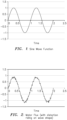
- An AC induction motor like element 20 e.g., for driving a pump like element 30 ( Fig. 4 ), is designed to draw a pure sinusoid waveform of current when supplied with a sinusoid AC voltage. For example, see the sine wave function shown in Figure 1 .
- the waveform in Figure 2 e.g., received from the motor magnetic flux sensor like element 20b, has a sinewave component with distortion riding on the wave shape.
- the flux distortion is the indicating component of anomalies that allow for diagnosis of abnormalities.
- This flux distortion could indicate either mechanical or electrical pending failure. Examples of mechanical failure are vibration caused by misalignment, out of balance, failing bearings, etc. Examples of electrical failure could also be representative of the motor's windings or rotor developing a pending failure, e.g. partially shorted winding, broken rotor bar, eccentric air gap, damaged laminations, etc.
- the technique herein proposes to sense the fundamental frequency of the magnetic flux, and mathematically subtract the exact same frequency as a pure sinusoid waveform.
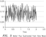
- the signal that remains is the non-sinusoid magnetic flux (see Figure 3 ), which can be processed to diagnose potential motor and/or load problems.
- One very important technique is a dynamically boosted gain of the resultant signal to allow much improved examination of minor flux distortions. By greatly amplifying these very small signals, improved diagnosis of previously undiscovered anomalies can be performed.
- fundamental sinewave cancellation allows for a motor's non sinusoidal flux "signature" to be recorded (e.g., sensed and stored in a suitable memory module like that forming part of element 10b) during a period of known proper operation, also called “base lining".
- baseline lining a period of known proper operation
- a spectral analysis e.g. using a Fast Fourier Transform analysis, can easily be performed to indicate anomalies from normal operation.
- a motor leakage sensor like element 20b attached to the outer frame like element 20a of the motor 20 By using a motor leakage sensor like element 20b attached to the outer frame like element 20a of the motor 20, one can non-invasively sense motor leakage. By subtracting the known good sinusoidal signal from the motor's non-sinusoidal flux signature, one can record a baseline of a known good working motor. That unique profile can be used to compare against future anomalies to determine pending failure.
- implementations are also envisioned using the addition of current sensors like 20d to sense motor current verses leakage flux sensors, but the same method could be used to trend the motor's current signature and compare future operations. However, adding current sensors like 20d would be an invasive solution.
- FIG. 4 The Basic Apparatus 10, including a Pump System
- Figure 4 shows apparatus generally indicated as 10 according to an implementation of the present invention, e.g., including a combination of a signal processor or signal processing module 10a, other signal processor circuits or components 10b, the motor 20 and the pump 30.
- the signal processor or signal processor module 10a may be configured to
- the functionality of the signal processor 10a may be implemented using hardware, software, firmware, or a combination thereof.
- the signal processor or signal processing module 10a would include one or more microprocessor-based architectures having, e. g., at least one processor or microprocessor, random access memory (RAM) and/or read only memory (ROM), input/output devices and control, and data and address buses connecting the same, and/or at least one input processor and at least one output processor.
- RAM random access memory
- ROM read only memory
- a person skilled in the art would be able to program such a microcontroller (or microprocessor)-based implementation to perform the functionality described herein without undue experimentation.
- the scope of the invention is intended to include implementing the functionality of the signal processor as stand-alone processor or processor module, as separate processor or processor modules, as well as some combination thereof.
- the signal processor 10a may include the signal processor 10a cooperating, or working in conjunction with, the input/output module forming part of the other component or circuitry forming part of element 10b.
- the signal processor 10a may be configured to use the baseline signature analysis to process the non-sinusoidal waveform, e.g., like that shown in Figure 3 , and determine the information about the anomalies in the motor 20 based upon the irregularities in the sensed motor flux that distort the waveform of the magnetic flux sensed by the motor leakage sensor 20b and caused by the vibration.
- the baseline signature analysis to process the non-sinusoidal waveform, e.g., like that shown in Figure 3 , and determine the information about the anomalies in the motor 20 based upon the irregularities in the sensed motor flux that distort the waveform of the magnetic flux sensed by the motor leakage sensor 20b and caused by the vibration.
- corresponding baseline signature analysis techniques to determine other type or kind of electrical and/or mechanical anomalies in the motor.
- the apparatus 10 may also include one or more other modules, components, etc. generally indicated as 10b for implementing other functionality associated with the apparatus, but that does not form part of the underlying invention and is not described in detail.
- the apparatus may also include the motor 20 having the outer housing 20a with the motor leakage flux detector 20b attached thereto, e.g., as shown in Figure 5 .
- the motor 20 may also include a rotor and stator combination 20c with windings, the current sensors 20d, as well as other motor components 20e that are known in the art.
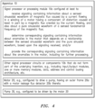
- Figure 6 shows a flow chart 50 of a method/algorithm having steps for determining anomalies in a motor, according to some aspects of the present invention, e.g., including implementing some combination of steps 50a, 50b, 50c and 50d.
- the flowchart 50 includes, e.g., a step 50d for arranging the outer frame 20a of the motor 20 with the motor leakage flux detector 20b to sense the sinusoidal waveform of the current flowing in the winding of the motor having the distortion caused at least in part by the magnetic flux created by the current flowing.
Landscapes
- Physics & Mathematics (AREA)
- General Physics & Mathematics (AREA)
- Condensed Matter Physics & Semiconductors (AREA)
- Control Of Ac Motors In General (AREA)
- Control Of Electric Motors In General (AREA)
- External Artificial Organs (AREA)
- Tests Of Circuit Breakers, Generators, And Electric Motors (AREA)
Description
- This application relates to a technique for detecting motor leakage flux anomalies; and more particularly to technique for detecting motor leakage flux anomalies in a motor.
- The following techniques are known in the art:
EP 1046044 B1 discloses a technique based upon using a differential current transformer to sense ground leakage current, and processes the signal to allow easy alarm trips, e.g., using a current transformer (amps) sensor placed in series with the power conductors feeding the motor. TheEP 1046044 B1 technique does not track the motor load via the leakage flux and a flux sensor to sense changes in the load to indicate anomalies in operation before catastrophic damage occurs. -
US Patent No. 5,680,025 discloses a technique that uses a flux coil to sense motor load and flux signals, but does not disclose the ability to cancel out sinusoids. -
US Patent No. 6,308,140 B1 discloses a technique that senses motor current, not flux, and uses the motor current to detect broken rotor bars in the motor. -
US Patent No. 7,880,473 discloses a technique for non-invasive monitoring and diagnosis of a motor by measuring external flex density by comparing a combined value of magnetic field values measured at various points external to the motor to an expected combined value to determine if a fault is present in the motor. -
US Patent No. 4,808,932 discloses a method and apparatus for detecting rotor faults in an induction motor. The flux around the rotor bars is detected using a coil wound around one of the stator teeth. -
US Patent No. 5,739,698 discloses a method for nonintrusive detection of anomalies in electric machines. A flux coil obtains magnetic leakage flux measurements, which are then transformed to the frequency domain to obtain a flux spectrum. -
US Patent No. 5,252,915 discloses a device capable of detecting anomalies in a machine by analysing axial leakage flux. Harmonic components in the flux which are normally present in a healthy machine can be mathematically predicted. - No technique are known in the art for sensing motor flux non-invasively, and cancelling out sinusoid waveforms and using the resultant signal for baselining and trending, thereby allowing for accurate comparing and diagnosis for the purpose of indicating pending motor failure with an accurate diagnosis.
- In view of this, there is a need in the industry for a better way for detecting electrical and mechanical faults in a motor driving a pump.
- In summary, and in contrast to the prior art techniques set forth above, the present invention provides a new and unique technique for detecting motor leakage flux anomalies, which is based upon attached a magnetic flux sensor to the motor frame. In particular, a motor leakage flux detector, e.g., including a fluxgate device, may be attached to the motor's outer frame.
- Embodiments of the present invention are defined in the
apparatus claim 1 and the method claim 13. Further embodiments are defined in the corresponding dependent claims. The description and drawings also present additional aspects, examples, and implementations for the better understanding of the claimed embodiments defined in the claims. - In effect, the present invention provides a new and unique technique for sensing motor flux non-invasively, and cancelling out sinusoid waveforms and using the resultant signal for baselining and trending, thereby allowing for accurate comparing and diagnosis for the purpose of indicating pending motor failure with an accurate diagnosis.
- The drawing, not necessarily drawn to scale, includes the following Figures:
-
Figure 1 shows a graph of a sine wave function (amplitude vs. time) of a pure sinusoid waveform of current, e.g., which is typically provided to an AC induction motor. -
Figure 2 shows a graph of a waveform (amplitude vs. time) of magnetic flux created by the current flowing in the AC induction motor, e.g., received from a motor magnetic flux sensor attached to an outer frame of the motor, having a sinewave component with distortion riding on the wave shape. -
Figure 3 shows a graph of a non-sinusoidal waveform (amplitude vs. time) of magnetic flux minus the sine wave function by the current flowing in the AC induction motor, e.g., for diagnosing potential motor and/or load problems. -
Figure 4 shows apparatus having a signal processor configured to process signaling received and determine corresponding signaling containing information about anomalies in a motor, e.g., for driving a pump, according to some embodiments of the present invention. -
Figure 5 shows a block diagram of a motor having an outer frame with a motor leakage flux detector arranged thereon, e.g., including a fluxgate device, according to some embodiments of the present invention. -
Figure 6 shows a flowchart of a basic method/algorithm, according to some embodiments of the present invention. - Not every reference numeral is included in every Figure, e.g., so as to reduce clutter in the drawing as a whole.
- An AC induction motor like element 20 (
Fig. 4 ), e.g., for driving a pump like element 30 (Fig. 4 ), is designed to draw a pure sinusoid waveform of current when supplied with a sinusoid AC voltage. For example, see the sine wave function shown inFigure 1 . - This current flowing in the motor's windings (20c (
Fig. 5 )) will create a sinusoid of magnetic flux. According to the present invention, for diagnosis of motor and/or load problems, it is imperative to examine the magnetic flux that is not sinusoidal. For example, see the motor flux function shown inFigure 2 . - The waveform in
Figure 2 , e.g., received from the motor magnetic flux sensor like element 20b, has a sinewave component with distortion riding on the wave shape. The flux distortion is the indicating component of anomalies that allow for diagnosis of abnormalities. This flux distortion could indicate either mechanical or electrical pending failure. Examples of mechanical failure are vibration caused by misalignment, out of balance, failing bearings, etc. Examples of electrical failure could also be representative of the motor's windings or rotor developing a pending failure, e.g. partially shorted winding, broken rotor bar, eccentric air gap, damaged laminations, etc. - According to the present invention, the technique herein proposes to sense the fundamental frequency of the magnetic flux, and mathematically subtract the exact same frequency as a pure sinusoid waveform. The signal that remains is the non-sinusoid magnetic flux (see
Figure 3 ), which can be processed to diagnose potential motor and/or load problems. - Numerous processes can be performed on the resultant signal. For example, one very important technique is a dynamically boosted gain of the resultant signal to allow much improved examination of minor flux distortions. By greatly amplifying these very small signals, improved diagnosis of previously undiscovered anomalies can be performed.
- In addition, fundamental sinewave cancellation allows for a motor's non sinusoidal flux "signature" to be recorded (e.g., sensed and stored in a suitable memory module like that forming part of element 10b) during a period of known proper operation, also called "base lining". This ability to provide a very detailed comparison to the non-sinusoidal component allows for a more accurate baseline signal to be established during a known good operational period.
- By performing a comparison analysis of a questionable signal to the baseline signal recorded, minimum deviation over time regarding wave shape in both amplitude and frequency can be determined. By establishing an alarm threshold for a deviation value that indicates an abnormal condition, but not a condition to cause immediate damage, the user may investigate a potential abnormal condition while the system is running, and not stopped due to a damaging fault.
- Lastly, a spectral analysis, e.g. using a Fast Fourier Transform analysis, can easily be performed to indicate anomalies from normal operation.
- By using a motor leakage sensor like element 20b attached to the outer frame like
element 20a of themotor 20, one can non-invasively sense motor leakage. By subtracting the known good sinusoidal signal from the motor's non-sinusoidal flux signature, one can record a baseline of a known good working motor. That unique profile can be used to compare against future anomalies to determine pending failure. - By way of further example, implementations are also envisioned using the addition of current sensors like 20d to sense motor current verses leakage flux sensors, but the same method could be used to trend the motor's current signature and compare future operations. However, adding current sensors like 20d would be an invasive solution.
-
Figure 4 shows apparatus generally indicated as 10 according to an implementation of the present invention, e.g., including a combination of a signal processor or signal processing module 10a, other signal processor circuits or components 10b, themotor 20 and the pump 30. - In operation, the signal processor or signal processor module 10a may be configured to
- receive signaling containing information about a sensed sinusoidal waveform of magnetic flux caused by a current flowing in a winding of a motor having a component of distortion caused at least in part by a magnetic flux created by the current flowing, and also about a pure sinusoidal waveform of a sensed fundamental frequency of the magnetic flux; and
- determine corresponding signaling containing information about anomalies in the motor that depends on a relationship between the sensed sinusoidal waveform and the pure sinusoid waveform, based upon the signaling received.
- By way of example, the functionality of the signal processor 10a may be implemented using hardware, software, firmware, or a combination thereof. In a typical software implementation, the signal processor or signal processing module 10a would include one or more microprocessor-based architectures having, e. g., at least one processor or microprocessor, random access memory (RAM) and/or read only memory (ROM), input/output devices and control, and data and address buses connecting the same, and/or at least one input processor and at least one output processor. A person skilled in the art would be able to program such a microcontroller (or microprocessor)-based implementation to perform the functionality described herein without undue experimentation. The scope of the invention is intended to include implementing the functionality of the signal processor as stand-alone processor or processor module, as separate processor or processor modules, as well as some combination thereof.
- By way of example, after reading the instant patent application, one skilled in the art would appreciate without undue experimentation how to implement the signal processor 10a to receive the signaling containing information about the sensed sinusoidal waveform of magnetic flux caused by the current flowing in the winding of the motor having the component of distortion caused at least in part by the magnetic flux created by the current flowing, and also about the pure sinusoidal waveform of the sensed fundamental frequency of the magnetic flux. The implementation may include the signal processor 10a cooperating, or working in conjunction with, the input/output module forming part of the other component or circuitry forming part of element 10b.
- By way of further example, after reading the instant patent application, one skilled in the art would appreciate without undue experimentation how to implement the signal processor 10a to determine the corresponding signaling containing information about the anomalies in the motor that depends on the relationship between the sensed sinusoidal waveform and the pure sinusoid waveform, e.g., including mechanical and/or electrical anomalies as set forth herein. By way of example, vibration of the motor and the motor leakage sensor 20b in relation to the windings of the motor may cause irregularities in the sensed motor flux that may distort the waveform of the magnetic flux sensed by the motor leakage sensor 20b. The signal processor 10a may be configured to use the baseline signature analysis to process the non-sinusoidal waveform, e.g., like that shown in
Figure 3 , and determine the information about the anomalies in themotor 20 based upon the irregularities in the sensed motor flux that distort the waveform of the magnetic flux sensed by the motor leakage sensor 20b and caused by the vibration. Similarly, one skilled in the art without undue experimentation would also be able to implement corresponding baseline signature analysis techniques to determine other type or kind of electrical and/or mechanical anomalies in the motor. - It is important to note that the scope of the invention is not intended to be limited to any particular type or kind of electrical and/or mechanical anomaly in the motor determined, and may include known anomalies.
- The apparatus 10 may also include one or more other modules, components, etc. generally indicated as 10b for implementing other functionality associated with the apparatus, but that does not form part of the underlying invention and is not described in detail.
- The apparatus may also include the
motor 20 having theouter housing 20a with the motor leakage flux detector 20b attached thereto, e.g., as shown inFigure 5 . By way of further example, themotor 20 may also include a rotor andstator combination 20c with windings, thecurrent sensors 20d, as well asother motor components 20e that are known in the art. -
Figure 6 shows aflow chart 50 of a method/algorithm having steps for determining anomalies in a motor, according to some aspects of the present invention, e.g., including implementing some combination ofsteps flowchart 50 includes, e.g., a step 50d for arranging theouter frame 20a of themotor 20 with the motor leakage flux detector 20b to sense the sinusoidal waveform of the current flowing in the winding of the motor having the distortion caused at least in part by the magnetic flux created by the current flowing.
Claims (13)
- Apparatus comprising:a motor (20) having an outer motor frame (20a) and configured to drive a pump (30);a motor magnetic flux sensor (20b) attached to the outer motor frame (20a), the sensor configured to:sense signaling containing information about a sensed sinusoidal waveform of magnetic flux caused by a current flowing in a winding of the motor (20) having a component of distortion caused at least in part by a magnetic flux created by the current flowing, and also about a pure sinusoidal waveform of a sensed fundamental frequency of the magnetic flux;a signal processor (10a) configured to:receive the signaling sensed by the sensor;subtract the pure sinusoidal waveform from the sensed sinusoidal waveform to determine a difference between the sensed sinusoidal waveform and the pure sinusoidal waveform of the fundamental frequency of the magnetic flux, resulting in a non-sinusoid magnetic flux waveform of magnetic flux distortion;wherein the signal processor (10a) is further configured to store and record in a memory module (10b) baseline signaling containing information about a baseline difference for subsequent comparison with a subsequent difference determined at a later point in time;perform a comparison of the non-sinusoid magnetic flux waveform of magnetic flux distortion to the baseline difference; anddetermine corresponding signaling containing information about anomalies in the motor (20) that depends on the comparison, based upon the signaling received.
- Apparatus according to claim 1, wherein the motor magnetic flux sensor (20b) is a leakage magnetic flux sensor.
- Apparatus according to claim 1, wherein the sensed sinusoidal waveform has a sinewave component with distortion riding on the sensed sinusoidal waveform.
- Apparatus according to claim 1, wherein the magnetic flux distortion contains information about either mechanical or electrical pending failure.
- Apparatus according to claim 4, wherein mechanical failure includes vibration caused by a misalignment, an out of balance condition, or one or more failing bearings, and optionally wherein the corresponding signaling determined contains information about the mechanical failure, including the vibration caused by the misalignment, the out of balance condition, or the one or more failing bearings.
- Apparatus according to claim 4, wherein electrical failure includes a partially shorted winding, a broken rotor bar, an eccentric air gap, or damaged laminations, and optionally wherein the corresponding signaling determined contains information about the electrical failure, including the partially shorted winding, the broken rotor bar, the eccentric air gap, or the damaged laminations.
- Apparatus according to claim 1, wherein the signal processor (10a) is configured to process associated signaling containing information about the sinusoid magnetic flux waveform to determine mechanical or electrical pending failure, using one or more of the following techniques:implementing a dynamically boosted gain technique on the associated signaling to amplify minor flux distortions for further analysis; orimplementing a fundamental sinewave cancellation technique comprising:recording/storing a motor's non sinusoidal flux "signature" during a period of known proper operation for establishing a motor's non sinusoidal flux "signature" baseline;recording/storing a subsequent motor's non sinusoidal flux "signature" during a subsequent period of operation; anddetermining, by a comparison analysis of the motor's non sinusoidal flux "signature" baseline and the subsequent motor's non sinusoidal flux "signature", one or more minimum deviations over time regarding corresponding wave shapes in both amplitude and frequency; orestablishing an alarm threshold for a deviation value that indicates an abnormal condition, including where the abnormal condition is not a condition to cause immediate damage, so the motor (20) is investigated for a potential abnormal condition while the motor is running, and not stopped due to a damaging fault.
- Apparatus according to claim 1, wherein the signal processor (10a) is configured to process associated signaling containing information about the non-sinusoid magnetic flux waveform by performing a spectral analysis, including using Fast Fourier Transform analysis, to determine the anomalies based upon a comparison a baseline sinusoidal waveform determined during normal operation at a first point in time and a subsequent sinusoidal waveform determined at a second and later point in time, and optionally wherein the signaling received at the first point in time contains information about the baseline sinusoidal waveform of the current flowing in the winding of the motor having the distortion caused at least in part by the magnetic flux created by the current flowing during the normal operation, and the signaling received at the second point in time contains information about the subsequent sinusoidal waveform of the current flowing in the winding of the motor having the distortion caused at least in part by the magnetic flux created by the current flowing at the second and later point in time.
- Apparatus according to claim 1, wherein the motor (20) is an AC induction motor configured to draw a pure sinusoid waveform of current when supplied with sinusoid AC voltage.
- Apparatus according to claim 1, wherein the signal processor (10a) is configured to decompose the signaling received to determine first signaling containing information about the sinusoidal waveform of the current flowing in the winding of the motor, and determine second signaling containing information about the distortion caused at least in part by the magnetic flux created by the current flowing.
- Apparatus according to claim 1, wherein the signaling received includes first signaling containing information about the sinusoidal waveform of the current flowing in the winding of the motor (20), and includes second signaling containing information about the distortion caused at least in part by the magnetic flux created by the current flowing.
- Apparatus according to claim 1, wherein the signal 2. processor (10a) is configured to provide the corresponding signaling determined containing information about the anomalies in the motor (20).
- A method comprising:sensing, with a motor magnetic flux sensor (20b) attached to an outer motor frame (20a) of a motor (20), signaling containing information about a sensed sinusoidal waveform of magnetic flux caused by a current flowing in a winding of the motor (20) having a component of distortion caused at least in part by a magnetic flux created by the current flowing and also about a pure sinusoidal waveform of a sensed fundamental frequency of the magnetic flux;receiving, by a signal processor (10a), said signaling;subtracting, by the signal processor (10a), the pure sinusoidal waveform from the sensed sinusoidal waveform to determine a difference between the sensed sinusoidal waveform and the pure sinusoidal waveform of the fundamental frequency of the magnetic flux, resulting in a non-sinusoid magnetic flux waveform of magnetic flux distortion;the signal processor (10a) storing and recording in a memory module (10b) baseline signaling containing information about a baseline difference for subsequent comparison with a subsequent difference determined at a later point in time;the signal processor (10a) performing a comparison of the non-sinusoid magnetic flux waveform of magnetic flux distortion to the baseline difference; anddetermining, by the signal processor (10a), corresponding signaling containing information about anomalies in the motor (20) that depends on the comparison, based upon the signaling received.
Applications Claiming Priority (2)
| Application Number | Priority Date | Filing Date | Title |
|---|---|---|---|
| US15/648,855 US10514428B2 (en) | 2017-07-13 | 2017-07-13 | Technique to detect motor leakage flux anomalies |
| PCT/US2018/041805 WO2019014438A1 (en) | 2017-07-13 | 2018-07-12 | Technique to detect motor leakage flux anomalies |
Publications (2)
| Publication Number | Publication Date |
|---|---|
| EP3652551A1 EP3652551A1 (en) | 2020-05-20 |
| EP3652551B1 true EP3652551B1 (en) | 2023-11-01 |
Family
ID=63244949
Family Applications (1)
| Application Number | Title | Priority Date | Filing Date |
|---|---|---|---|
| EP18755948.9A Active EP3652551B1 (en) | 2017-07-13 | 2018-07-12 | Technique to detect motor leakage flux anomalies |
Country Status (17)
| Country | Link |
|---|---|
| US (2) | US10514428B2 (en) |
| EP (1) | EP3652551B1 (en) |
| JP (1) | JP2020527017A (en) |
| KR (1) | KR20200028407A (en) |
| CN (1) | CN110998343A (en) |
| AU (1) | AU2018300989B2 (en) |
| BR (1) | BR112020000609A2 (en) |
| CA (1) | CA3069857A1 (en) |
| DK (1) | DK3652551T3 (en) |
| ES (1) | ES2965665T3 (en) |
| FI (1) | FI3652551T3 (en) |
| HU (1) | HUE064668T2 (en) |
| MX (1) | MX2020000463A (en) |
| PL (1) | PL3652551T3 (en) |
| PT (1) | PT3652551T (en) |
| RU (1) | RU2020106574A (en) |
| WO (1) | WO2019014438A1 (en) |
Families Citing this family (7)
| Publication number | Priority date | Publication date | Assignee | Title |
|---|---|---|---|---|
| FR3088439B1 (en) * | 2018-11-12 | 2020-11-13 | Electricite De France | ELECTRICAL FAULT DETECTION IN A GENERATOR |
| US11500037B2 (en) * | 2019-08-05 | 2022-11-15 | Sembcorp Industries Ltd | Method and a system of detecting winding fault under online operation of an electrical machine |
| KR102493056B1 (en) | 2020-03-06 | 2023-01-30 | 엘지전자 주식회사 | Laundry Treatment Apparatus And Assembly Method Of The Same |
| US11378491B2 (en) * | 2020-04-03 | 2022-07-05 | Itt Manufacturing Enterprises Llc | Bearing frame monitoring system |
| CN113219277A (en) * | 2021-04-16 | 2021-08-06 | 唐山不锈钢有限责任公司 | Method for detecting roller bearing degradation by adopting motor current |
| KR102544604B1 (en) * | 2021-04-27 | 2023-06-16 | 고려대학교 산학협력단 | Method for detection of fault of synchronous machine |
| KR102572908B1 (en) * | 2023-06-01 | 2023-08-31 | 주식회사 에이테크 | Method and Apparatus for Diagnosing Dynamic Eccentricity of Electric Vehicle Traction Motor |
Family Cites Families (68)
| Publication number | Priority date | Publication date | Assignee | Title |
|---|---|---|---|---|
| US4808932A (en) | 1987-05-15 | 1989-02-28 | Electric Power Research Institute, Inc. | Rotor fault and location detector for induction motors |
| US4761703A (en) | 1987-08-31 | 1988-08-02 | Electric Power Research Institute, Inc. | Rotor fault detector for induction motors |
| US5049815A (en) | 1990-04-20 | 1991-09-17 | General Electric Company | Spectral analysis of induction motor current to detect rotor faults with reduced false alarms |
| US5252915A (en) | 1992-01-23 | 1993-10-12 | Ontario Hydro | Method and apparatus for detecting stator faults in rotary dynamoelectric machines |
| US5612601A (en) | 1993-11-22 | 1997-03-18 | Martin Marietta Energy Systems, Inc. | Method for assessing motor insulation on operating motors |
| US5594175A (en) | 1994-05-06 | 1997-01-14 | Massachusetts Institute Of Technology | Apparatus and method for non-invasive diagnosis and control of motor operated valve condition |
| US5629870A (en) | 1994-05-31 | 1997-05-13 | Siemens Energy & Automation, Inc. | Method and apparatus for predicting electric induction machine failure during operation |
| US5477163A (en) | 1994-08-03 | 1995-12-19 | General Electric Company | Turn fault detection |
| US5680025A (en) | 1994-10-07 | 1997-10-21 | Csi Technology, Inc. | Proactive motor monitoring for avoiding premature failures and for fault recognition |
| US5530343A (en) | 1994-10-07 | 1996-06-25 | Computational Systems, Inc. | Induction motor speed determination by flux spectral analysis |
| US5726905A (en) | 1995-09-27 | 1998-03-10 | General Electric Company | Adaptive, on line, statistical method and apparatus for motor bearing fault detection by passive motor current monitoring |
| US5742522A (en) | 1996-04-01 | 1998-04-21 | General Electric Company | Adaptive, on line, statistical method and apparatus for detection of broken bars in motors by passive motor current monitoring and digital torque estimation |
| US5786708A (en) | 1996-04-01 | 1998-07-28 | General Electric Company | Self-tuning and compensating turn fault detector |
| US6144924A (en) | 1996-05-20 | 2000-11-07 | Crane Nuclear, Inc. | Motor condition and performance analyzer |
| US5739698A (en) | 1996-06-20 | 1998-04-14 | Csi Technology, Inc. | Machine fault detection using slot pass frequency flux measurements |
| US6014598A (en) | 1996-06-28 | 2000-01-11 | Arcelik A.S. | Model-based fault detection system for electric motors |
| US5726911A (en) | 1996-08-22 | 1998-03-10 | Csi Technology, Inc. | Electric motor monitor |
| US6138078A (en) | 1996-08-22 | 2000-10-24 | Csi Technology, Inc. | Machine monitor with tethered sensors |
| US6064172A (en) | 1997-02-11 | 2000-05-16 | Power Superconductor Applications Corporation | Method and apparatus for detection, classification and reduction of internal electrical faults in alternating current propulsion machinery using synchronous detection scheme |
| US6199018B1 (en) | 1998-03-04 | 2001-03-06 | Emerson Electric Co. | Distributed diagnostic system |
| US7024335B1 (en) | 1998-04-15 | 2006-04-04 | The Texas A&M University System | Condition assessment and life expectancy prediction for devices |
| US7308322B1 (en) | 1998-09-29 | 2007-12-11 | Rockwell Automation Technologies, Inc. | Motorized system integrated control and diagnostics using vibration, pressure, temperature, speed, and/or current analysis |
| US6169489B1 (en) | 1998-10-07 | 2001-01-02 | General Electric Company | Motor winding contamination detector and detection |
| US6172509B1 (en) | 1999-02-11 | 2001-01-09 | The United States Of America As Represented By The Secretary Of The Air Force | Detecting polyphase machine faults via current deviation |
| US6636823B1 (en) | 1999-09-30 | 2003-10-21 | Rockwell Automation Technologies, Inc. | Method and apparatus for motor fault diagnosis |
| US6529135B1 (en) | 1999-10-12 | 2003-03-04 | Csi Technology, Inc. | Integrated electric motor monitor |
| US6262550B1 (en) | 1999-12-17 | 2001-07-17 | General Electric Company | Electrical motor monitoring system and method |
| US6590362B2 (en) | 2001-07-27 | 2003-07-08 | Texas A&M University System | Method and system for early detection of incipient faults in electric motors |
| JP3671369B2 (en) * | 2001-11-26 | 2005-07-13 | エイテック株式会社 | Electrical equipment abnormality and deterioration diagnosis device |
| US20030193310A1 (en) | 2002-04-12 | 2003-10-16 | Ford Motor Company | Diagnostic method for an electric motor using torque estimates |
| US7116068B2 (en) | 2002-04-12 | 2006-10-03 | Ford Global Technologies, Llc | Diagnostic system and method for an electric motor using torque estimates |
| GB0217494D0 (en) | 2002-07-29 | 2002-09-04 | Boc Group Plc | Conditioning monitoring of pumps and pump systems |
| US6834256B2 (en) | 2002-08-30 | 2004-12-21 | General Electric Company | Method and system for determining motor reliability |
| US6941785B2 (en) | 2003-05-13 | 2005-09-13 | Ut-Battelle, Llc | Electric fuel pump condition monitor system using electrical signature analysis |
| US7231319B2 (en) | 2003-06-18 | 2007-06-12 | Eaton Corporation | System and method for proactive motor wellness diagnosis based on potential cavitation faults |
| GB0319553D0 (en) | 2003-08-20 | 2003-09-24 | Rolls Royce Plc | Condition monitoring |
| US7254514B2 (en) | 2005-05-12 | 2007-08-07 | General Electric Company | Method and system for predicting remaining life for motors featuring on-line insulation condition monitor |
| DE102005032720B4 (en) | 2005-07-13 | 2007-04-05 | Siemens Ag | Interface module device for an electric machine for calculating the service life of a bearing |
| US7277800B2 (en) | 2006-02-28 | 2007-10-02 | The Boeing Company | Freeplay monitor |
| US8103463B2 (en) | 2006-09-21 | 2012-01-24 | Impact Technologies, Llc | Systems and methods for predicting failure of electronic systems and assessing level of degradation and remaining useful life |
| WO2008148075A1 (en) | 2007-05-24 | 2008-12-04 | Alexander George Parlos | Machine condition assessment through power distribution networks |
| US7847580B2 (en) | 2007-06-04 | 2010-12-07 | Eaton Corporation | System and method for motor fault detection using stator current noise cancellation |
| US20090096405A1 (en) | 2007-10-15 | 2009-04-16 | General Electric Company | Method and system for remotely predicting the remaining life of an ac motor system |
| US7646308B2 (en) | 2007-10-30 | 2010-01-12 | Eaton Corporation | System for monitoring electrical equipment and providing predictive diagnostics therefor |
| US7880473B2 (en) | 2008-03-31 | 2011-02-01 | General Electric Company | Non-invasive monitoring and diagnosis of electric machines by measuring external flux density |
| JP5100528B2 (en) * | 2008-06-19 | 2012-12-19 | 三菱電機株式会社 | Single-phase induction motor air gap eccentricity inspection apparatus, air gap eccentricity inspection method, air gap eccentricity adjustment method, and single-phase induction motor manufactured using the same |
| US8095324B2 (en) | 2008-06-26 | 2012-01-10 | Pratt & Whitney Canada Corp. | Permanent magnet rotor crack detection |
| US9261562B2 (en) | 2008-10-04 | 2016-02-16 | Skf Usa, Inc. | Portable system for immotive multiphasic motive force electrical machine testing |
| US8217644B2 (en) | 2009-07-09 | 2012-07-10 | General Electric Company | High sensitivity differential current transformer for insulation health monitoring |
| US7977963B2 (en) * | 2009-07-21 | 2011-07-12 | GM Global Technology Operations LLC | Methods, systems and apparatus for detecting abnormal operation of an inverter sub-module |
| US8253365B2 (en) | 2009-10-20 | 2012-08-28 | GM Global Technology Operations LLC | Methods and systems for performing fault diagnostics for rotors of electric motors |
| US8378605B2 (en) | 2010-01-06 | 2013-02-19 | GM Global Technology Operations LLC | Method and apparatus for monitoring a system including a sensorless electric motor |
| US8401822B2 (en) | 2010-04-20 | 2013-03-19 | Eaton Corporation | System, wellness circuit and method of determining wellness of a rotating electrical apparatus |
| CA2799402C (en) | 2010-05-14 | 2020-10-06 | Harnischfeger Technologies, Inc. | Cycle decomposition analysis for remote machine monitoring |
| US8405339B2 (en) | 2010-07-01 | 2013-03-26 | Eaton Corporation | System and method for detecting fault in an AC machine |
| AU2012238916B2 (en) | 2011-04-08 | 2015-09-17 | Abb Schweiz Ag | Subsea measurement and monitoring |
| US9845012B2 (en) | 2011-07-06 | 2017-12-19 | General Electric Company | System and method for predicting mechanical failure of a motor |
| US9097767B2 (en) | 2012-01-09 | 2015-08-04 | GM Global Technology Operations LLC | DC-motor and fuel pump faults and brush-wear prognosis |
| US9048767B2 (en) * | 2012-01-23 | 2015-06-02 | Hamilton Sundstrand Corporation | Motor drive for permanent magnet synchronous motor |
| CN102662108B (en) * | 2012-05-14 | 2014-06-18 | 中国航空工业集团公司北京长城计量测试技术研究所 | Measuring method and device of sine wave local distortion |
| US20140039817A1 (en) | 2012-08-06 | 2014-02-06 | Phase3 Technologies Ltd. | System and method for monitoring an electrically-connected system having a periodic behavior |
| US9255970B2 (en) | 2012-09-27 | 2016-02-09 | General Electric Company | On-line monitoring of stator insulation in motors and generators |
| KR101357827B1 (en) | 2012-12-07 | 2014-02-05 | 전자부품연구원 | Fault detection method type of parallel permanent magnet motor and system using the same |
| KR101357828B1 (en) | 2012-12-07 | 2014-02-05 | 전자부품연구원 | Fault detection method type of series permanent magnet motor and system using the same |
| CA2904734C (en) | 2013-03-15 | 2018-01-02 | Emerson Electric Co. | Hvac system remote monitoring and diagnosis |
| GB201404226D0 (en) | 2014-03-11 | 2014-04-23 | Rolls Royce Plc | Fault detection in induction machines |
| BR112016027402B1 (en) | 2014-05-23 | 2022-08-09 | Schlumberger Technology B.V. | METHOD AND SYSTEM FOR EVALUATION OF SUBMERSIBLE ELECTRICAL SYSTEM AND NON-TRANSITORY COMPUTER READable STORAGE MEDIA |
| KR101637756B1 (en) * | 2014-12-03 | 2016-07-07 | 현대자동차주식회사 | Fault diagnosis method for resolver |
-
2017
- 2017-07-13 US US15/648,855 patent/US10514428B2/en active Active
-
2018
- 2018-07-12 CN CN201880052418.3A patent/CN110998343A/en active Pending
- 2018-07-12 DK DK18755948.9T patent/DK3652551T3/en active
- 2018-07-12 BR BR112020000609-2A patent/BR112020000609A2/en not_active IP Right Cessation
- 2018-07-12 EP EP18755948.9A patent/EP3652551B1/en active Active
- 2018-07-12 FI FIEP18755948.9T patent/FI3652551T3/en active
- 2018-07-12 PL PL18755948.9T patent/PL3652551T3/en unknown
- 2018-07-12 KR KR1020207003102A patent/KR20200028407A/en not_active Ceased
- 2018-07-12 RU RU2020106574A patent/RU2020106574A/en not_active Application Discontinuation
- 2018-07-12 PT PT187559489T patent/PT3652551T/en unknown
- 2018-07-12 HU HUE18755948A patent/HUE064668T2/en unknown
- 2018-07-12 MX MX2020000463A patent/MX2020000463A/en unknown
- 2018-07-12 JP JP2020501373A patent/JP2020527017A/en active Pending
- 2018-07-12 AU AU2018300989A patent/AU2018300989B2/en not_active Expired - Fee Related
- 2018-07-12 WO PCT/US2018/041805 patent/WO2019014438A1/en not_active Ceased
- 2018-07-12 CA CA3069857A patent/CA3069857A1/en not_active Abandoned
- 2018-07-12 ES ES18755948T patent/ES2965665T3/en active Active
-
2019
- 2019-11-18 US US16/686,283 patent/US10976379B2/en active Active
Also Published As
| Publication number | Publication date |
|---|---|
| KR20200028407A (en) | 2020-03-16 |
| JP2020527017A (en) | 2020-08-31 |
| PL3652551T3 (en) | 2024-04-08 |
| WO2019014438A1 (en) | 2019-01-17 |
| US10514428B2 (en) | 2019-12-24 |
| DK3652551T3 (en) | 2023-12-18 |
| AU2018300989B2 (en) | 2020-04-30 |
| CA3069857A1 (en) | 2019-01-17 |
| ES2965665T3 (en) | 2024-04-16 |
| CN110998343A (en) | 2020-04-10 |
| US20190018073A1 (en) | 2019-01-17 |
| EP3652551A1 (en) | 2020-05-20 |
| MX2020000463A (en) | 2020-08-17 |
| RU2020106574A3 (en) | 2021-08-13 |
| US20200110138A1 (en) | 2020-04-09 |
| FI3652551T3 (en) | 2023-12-13 |
| PT3652551T (en) | 2023-12-19 |
| BR112020000609A2 (en) | 2020-07-14 |
| HUE064668T2 (en) | 2024-04-28 |
| US10976379B2 (en) | 2021-04-13 |
| RU2020106574A (en) | 2021-08-13 |
| AU2018300989A1 (en) | 2020-01-30 |
Similar Documents
| Publication | Publication Date | Title |
|---|---|---|
| AU2018300989B2 (en) | Technique to detect motor leakage flux anomalies | |
| US10088506B2 (en) | Method for detecting a fault condition in an electrical machine | |
| de Jesus Romero-Troncoso | Multirate signal processing to improve FFT-based analysis for detecting faults in induction motors | |
| US10310016B2 (en) | Method for the diagnostics of electromechanical system based on impedance analysis | |
| US10267860B2 (en) | Fault detection in induction machines | |
| KR101474187B1 (en) | Method for monitoring demagnetization | |
| US5739698A (en) | Machine fault detection using slot pass frequency flux measurements | |
| US20080309366A1 (en) | System and method for bearing fault detection using stator current noise cancellation | |
| US20090146599A1 (en) | System and method for motor fault detection using stator current noise cancellation | |
| US20100299090A1 (en) | Method for monitoring the shaft current and/or the insulation of the shaft of electric machines and device for performing the method | |
| CN115989418A (en) | Machine state monitoring method and machine state monitoring system | |
| JP2005538370A (en) | Method and apparatus for capturing vibration of a shaft assembly in an electric machine | |
| JP5670033B2 (en) | Method and system for handling stray magnetic flux | |
| JP5643372B2 (en) | Rotating machine pass / fail diagnosis system | |
| Yeolekar et al. | Outer race bearing fault identification of induction motor based on stator current signature by wavelet transform | |
| Frosini et al. | An improved diagnostic system to detect inter-turns short circuits in low voltage stator windings | |
| Ibragimov et al. | Exploration of the combined vibration parameters and external magnetic field in diagnosing asynchronous electric motors | |
| BR102015011438A2 (en) | system and method for identifying characteristics of an electrical machine | |
| US20190265299A1 (en) | Monitoring And Fault Diagnosis Of Electric Machines | |
| Fernández et al. | Control and Monitoring of Induction Machines Using Hall-effect Sensors | |
| BR102022025707A2 (en) | EQUIPMENT AND METHOD FOR MEASUREMENT OF IMPEDANCE AT MULTIPLE FREQUENCIES THROUGH INJECTION OF SIGNALS FOR ANALYSIS OF ELECTRICAL MACHINES | |
| KR100631020B1 (en) | Eccentric Condition Diagnosis Device of Induction Motor | |
| KR20060071516A (en) | Apparatus for detecting broken rotor-bar in induction motor |
Legal Events
| Date | Code | Title | Description |
|---|---|---|---|
| STAA | Information on the status of an ep patent application or granted ep patent |
Free format text: STATUS: UNKNOWN |
|
| STAA | Information on the status of an ep patent application or granted ep patent |
Free format text: STATUS: THE INTERNATIONAL PUBLICATION HAS BEEN MADE |
|
| PUAI | Public reference made under article 153(3) epc to a published international application that has entered the european phase |
Free format text: ORIGINAL CODE: 0009012 |
|
| STAA | Information on the status of an ep patent application or granted ep patent |
Free format text: STATUS: REQUEST FOR EXAMINATION WAS MADE |
|
| 17P | Request for examination filed |
Effective date: 20200131 |
|
| AK | Designated contracting states |
Kind code of ref document: A1 Designated state(s): AL AT BE BG CH CY CZ DE DK EE ES FI FR GB GR HR HU IE IS IT LI LT LU LV MC MK MT NL NO PL PT RO RS SE SI SK SM TR |
|
| AX | Request for extension of the european patent |
Extension state: BA ME |
|
| DAV | Request for validation of the european patent (deleted) | ||
| DAX | Request for extension of the european patent (deleted) | ||
| STAA | Information on the status of an ep patent application or granted ep patent |
Free format text: STATUS: EXAMINATION IS IN PROGRESS |
|
| 17Q | First examination report despatched |
Effective date: 20220412 |
|
| GRAP | Despatch of communication of intention to grant a patent |
Free format text: ORIGINAL CODE: EPIDOSNIGR1 |
|
| STAA | Information on the status of an ep patent application or granted ep patent |
Free format text: STATUS: GRANT OF PATENT IS INTENDED |
|
| INTG | Intention to grant announced |
Effective date: 20230511 |
|
| GRAS | Grant fee paid |
Free format text: ORIGINAL CODE: EPIDOSNIGR3 |
|
| GRAA | (expected) grant |
Free format text: ORIGINAL CODE: 0009210 |
|
| STAA | Information on the status of an ep patent application or granted ep patent |
Free format text: STATUS: THE PATENT HAS BEEN GRANTED |
|
| AK | Designated contracting states |
Kind code of ref document: B1 Designated state(s): AL AT BE BG CH CY CZ DE DK EE ES FI FR GB GR HR HU IE IS IT LI LT LU LV MC MK MT NL NO PL PT RO RS SE SI SK SM TR |
|
| P01 | Opt-out of the competence of the unified patent court (upc) registered |
Effective date: 20230926 |
|
| REG | Reference to a national code |
Ref country code: GB Ref legal event code: FG4D |
|
| REG | Reference to a national code |
Ref country code: CH Ref legal event code: EP |
|
| REG | Reference to a national code |
Ref country code: DE Ref legal event code: R096 Ref document number: 602018060396 Country of ref document: DE |
|
| REG | Reference to a national code |
Ref country code: IE Ref legal event code: FG4D |
|
| REG | Reference to a national code |
Ref country code: FI Ref legal event code: FGE |
|
| REG | Reference to a national code |
Ref country code: DK Ref legal event code: T3 Effective date: 20231214 |
|
| REG | Reference to a national code |
Ref country code: PT Ref legal event code: SC4A Ref document number: 3652551 Country of ref document: PT Date of ref document: 20231219 Kind code of ref document: T Free format text: AVAILABILITY OF NATIONAL TRANSLATION Effective date: 20231212 |
|
| REG | Reference to a national code |
Ref country code: SE Ref legal event code: TRGR |
|
| REG | Reference to a national code |
Ref country code: NL Ref legal event code: FP |
|
| REG | Reference to a national code |
Ref country code: NO Ref legal event code: T2 Effective date: 20231101 |
|
| REG | Reference to a national code |
Ref country code: GR Ref legal event code: EP Ref document number: 20230402420 Country of ref document: GR Effective date: 20240110 |
|
| REG | Reference to a national code |
Ref country code: LT Ref legal event code: MG9D |
|
| REG | Reference to a national code |
Ref country code: AT Ref legal event code: UEP Ref document number: 1627802 Country of ref document: AT Kind code of ref document: T Effective date: 20231101 |
|
| PG25 | Lapsed in a contracting state [announced via postgrant information from national office to epo] |
Ref country code: IS Free format text: LAPSE BECAUSE OF FAILURE TO SUBMIT A TRANSLATION OF THE DESCRIPTION OR TO PAY THE FEE WITHIN THE PRESCRIBED TIME-LIMIT Effective date: 20240301 |
|
| PG25 | Lapsed in a contracting state [announced via postgrant information from national office to epo] |
Ref country code: LT Free format text: LAPSE BECAUSE OF FAILURE TO SUBMIT A TRANSLATION OF THE DESCRIPTION OR TO PAY THE FEE WITHIN THE PRESCRIBED TIME-LIMIT Effective date: 20231101 |
|
| REG | Reference to a national code |
Ref country code: ES Ref legal event code: FG2A Ref document number: 2965665 Country of ref document: ES Kind code of ref document: T3 Effective date: 20240416 |
|
| REG | Reference to a national code |
Ref country code: HU Ref legal event code: AG4A Ref document number: E064668 Country of ref document: HU |
|
| PG25 | Lapsed in a contracting state [announced via postgrant information from national office to epo] |
Ref country code: LT Free format text: LAPSE BECAUSE OF FAILURE TO SUBMIT A TRANSLATION OF THE DESCRIPTION OR TO PAY THE FEE WITHIN THE PRESCRIBED TIME-LIMIT Effective date: 20231101 Ref country code: IS Free format text: LAPSE BECAUSE OF FAILURE TO SUBMIT A TRANSLATION OF THE DESCRIPTION OR TO PAY THE FEE WITHIN THE PRESCRIBED TIME-LIMIT Effective date: 20240301 Ref country code: BG Free format text: LAPSE BECAUSE OF FAILURE TO SUBMIT A TRANSLATION OF THE DESCRIPTION OR TO PAY THE FEE WITHIN THE PRESCRIBED TIME-LIMIT Effective date: 20240201 |
|
| PG25 | Lapsed in a contracting state [announced via postgrant information from national office to epo] |
Ref country code: RS Free format text: LAPSE BECAUSE OF FAILURE TO SUBMIT A TRANSLATION OF THE DESCRIPTION OR TO PAY THE FEE WITHIN THE PRESCRIBED TIME-LIMIT Effective date: 20231101 Ref country code: LV Free format text: LAPSE BECAUSE OF FAILURE TO SUBMIT A TRANSLATION OF THE DESCRIPTION OR TO PAY THE FEE WITHIN THE PRESCRIBED TIME-LIMIT Effective date: 20231101 Ref country code: HR Free format text: LAPSE BECAUSE OF FAILURE TO SUBMIT A TRANSLATION OF THE DESCRIPTION OR TO PAY THE FEE WITHIN THE PRESCRIBED TIME-LIMIT Effective date: 20231101 |
|
| PGFP | Annual fee paid to national office [announced via postgrant information from national office to epo] |
Ref country code: IE Payment date: 20240620 Year of fee payment: 7 |
|
| PGFP | Annual fee paid to national office [announced via postgrant information from national office to epo] |
Ref country code: DK Payment date: 20240619 Year of fee payment: 7 |
|
| PGFP | Annual fee paid to national office [announced via postgrant information from national office to epo] |
Ref country code: LU Payment date: 20240619 Year of fee payment: 7 Ref country code: GR Payment date: 20240620 Year of fee payment: 7 |
|
| PGFP | Annual fee paid to national office [announced via postgrant information from national office to epo] |
Ref country code: NL Payment date: 20240619 Year of fee payment: 7 |
|
| PGFP | Annual fee paid to national office [announced via postgrant information from national office to epo] |
Ref country code: CZ Payment date: 20240625 Year of fee payment: 7 |
|
| PG25 | Lapsed in a contracting state [announced via postgrant information from national office to epo] |
Ref country code: SK Free format text: LAPSE BECAUSE OF FAILURE TO SUBMIT A TRANSLATION OF THE DESCRIPTION OR TO PAY THE FEE WITHIN THE PRESCRIBED TIME-LIMIT Effective date: 20231101 |
|
| PG25 | Lapsed in a contracting state [announced via postgrant information from national office to epo] |
Ref country code: SM Free format text: LAPSE BECAUSE OF FAILURE TO SUBMIT A TRANSLATION OF THE DESCRIPTION OR TO PAY THE FEE WITHIN THE PRESCRIBED TIME-LIMIT Effective date: 20231101 Ref country code: SK Free format text: LAPSE BECAUSE OF FAILURE TO SUBMIT A TRANSLATION OF THE DESCRIPTION OR TO PAY THE FEE WITHIN THE PRESCRIBED TIME-LIMIT Effective date: 20231101 Ref country code: EE Free format text: LAPSE BECAUSE OF FAILURE TO SUBMIT A TRANSLATION OF THE DESCRIPTION OR TO PAY THE FEE WITHIN THE PRESCRIBED TIME-LIMIT Effective date: 20231101 |
|
| PGFP | Annual fee paid to national office [announced via postgrant information from national office to epo] |
Ref country code: NO Payment date: 20240620 Year of fee payment: 7 Ref country code: FR Payment date: 20240619 Year of fee payment: 7 Ref country code: FI Payment date: 20240619 Year of fee payment: 7 |
|
| PGFP | Annual fee paid to national office [announced via postgrant information from national office to epo] |
Ref country code: PL Payment date: 20240620 Year of fee payment: 7 Ref country code: PT Payment date: 20240621 Year of fee payment: 7 |
|
| REG | Reference to a national code |
Ref country code: DE Ref legal event code: R097 Ref document number: 602018060396 Country of ref document: DE |
|
| PGFP | Annual fee paid to national office [announced via postgrant information from national office to epo] |
Ref country code: SE Payment date: 20240619 Year of fee payment: 7 Ref country code: BE Payment date: 20240619 Year of fee payment: 7 |
|
| PLBE | No opposition filed within time limit |
Free format text: ORIGINAL CODE: 0009261 |
|
| STAA | Information on the status of an ep patent application or granted ep patent |
Free format text: STATUS: NO OPPOSITION FILED WITHIN TIME LIMIT |
|
| PGFP | Annual fee paid to national office [announced via postgrant information from national office to epo] |
Ref country code: IT Payment date: 20240619 Year of fee payment: 7 |
|
| 26N | No opposition filed |
Effective date: 20240802 |
|
| PGFP | Annual fee paid to national office [announced via postgrant information from national office to epo] |
Ref country code: ES Payment date: 20240802 Year of fee payment: 7 Ref country code: CH Payment date: 20240801 Year of fee payment: 7 |
|
| PGFP | Annual fee paid to national office [announced via postgrant information from national office to epo] |
Ref country code: AT Payment date: 20240620 Year of fee payment: 7 |
|
| PG25 | Lapsed in a contracting state [announced via postgrant information from national office to epo] |
Ref country code: SI Free format text: LAPSE BECAUSE OF FAILURE TO SUBMIT A TRANSLATION OF THE DESCRIPTION OR TO PAY THE FEE WITHIN THE PRESCRIBED TIME-LIMIT Effective date: 20231101 |
|
| PGFP | Annual fee paid to national office [announced via postgrant information from national office to epo] |
Ref country code: HU Payment date: 20240709 Year of fee payment: 7 |
|
| PG25 | Lapsed in a contracting state [announced via postgrant information from national office to epo] |
Ref country code: SI Free format text: LAPSE BECAUSE OF FAILURE TO SUBMIT A TRANSLATION OF THE DESCRIPTION OR TO PAY THE FEE WITHIN THE PRESCRIBED TIME-LIMIT Effective date: 20231101 |
|
| PGFP | Annual fee paid to national office [announced via postgrant information from national office to epo] |
Ref country code: TR Payment date: 20240702 Year of fee payment: 7 |
|
| PG25 | Lapsed in a contracting state [announced via postgrant information from national office to epo] |
Ref country code: MC Free format text: LAPSE BECAUSE OF FAILURE TO SUBMIT A TRANSLATION OF THE DESCRIPTION OR TO PAY THE FEE WITHIN THE PRESCRIBED TIME-LIMIT Effective date: 20231101 |
|
| PGFP | Annual fee paid to national office [announced via postgrant information from national office to epo] |
Ref country code: DE Payment date: 20250730 Year of fee payment: 8 |
|
| PGFP | Annual fee paid to national office [announced via postgrant information from national office to epo] |
Ref country code: GB Payment date: 20250724 Year of fee payment: 8 |
|
| PG25 | Lapsed in a contracting state [announced via postgrant information from national office to epo] |
Ref country code: RO Free format text: LAPSE BECAUSE OF FAILURE TO SUBMIT A TRANSLATION OF THE DESCRIPTION OR TO PAY THE FEE WITHIN THE PRESCRIBED TIME-LIMIT Effective date: 20231101 |
|
| PG25 | Lapsed in a contracting state [announced via postgrant information from national office to epo] |
Ref country code: CY Free format text: LAPSE BECAUSE OF FAILURE TO SUBMIT A TRANSLATION OF THE DESCRIPTION OR TO PAY THE FEE WITHIN THE PRESCRIBED TIME-LIMIT; INVALID AB INITIO Effective date: 20180712 |
|
| PG25 | Lapsed in a contracting state [announced via postgrant information from national office to epo] |
Ref country code: CZ Free format text: LAPSE BECAUSE OF NON-PAYMENT OF DUE FEES Effective date: 20250712 |
|
| REG | Reference to a national code |
Ref country code: DK Ref legal event code: EBP Effective date: 20250731 |
|
| REG | Reference to a national code |
Ref country code: CH Ref legal event code: H13 Free format text: ST27 STATUS EVENT CODE: U-0-0-H10-H13 (AS PROVIDED BY THE NATIONAL OFFICE) Effective date: 20260224 |
|
| REG | Reference to a national code |
Ref country code: NL Ref legal event code: MM Effective date: 20250801 |
|
| REG | Reference to a national code |
Ref country code: AT Ref legal event code: MM01 Ref document number: 1627802 Country of ref document: AT Kind code of ref document: T Effective date: 20250712 |
|
| PG25 | Lapsed in a contracting state [announced via postgrant information from national office to epo] |
Ref country code: LU Free format text: LAPSE BECAUSE OF NON-PAYMENT OF DUE FEES Effective date: 20250712 |
|
| PG25 | Lapsed in a contracting state [announced via postgrant information from national office to epo] |
Ref country code: HU Free format text: LAPSE BECAUSE OF NON-PAYMENT OF DUE FEES Effective date: 20250713 |
|
| REG | Reference to a national code |
Ref country code: BE Ref legal event code: MM Effective date: 20250731 |
|
| PG25 | Lapsed in a contracting state [announced via postgrant information from national office to epo] |
Ref country code: NO Free format text: LAPSE BECAUSE OF NON-PAYMENT OF DUE FEES Effective date: 20250731 |
|
| PG25 | Lapsed in a contracting state [announced via postgrant information from national office to epo] |
Ref country code: AT Free format text: LAPSE BECAUSE OF NON-PAYMENT OF DUE FEES Effective date: 20250712 Ref country code: FI Free format text: LAPSE BECAUSE OF NON-PAYMENT OF DUE FEES Effective date: 20250712 |
|
| PG25 | Lapsed in a contracting state [announced via postgrant information from national office to epo] |
Ref country code: BE Free format text: LAPSE BECAUSE OF NON-PAYMENT OF DUE FEES Effective date: 20250731 |
|
| PG25 | Lapsed in a contracting state [announced via postgrant information from national office to epo] |
Ref country code: NL Free format text: LAPSE BECAUSE OF NON-PAYMENT OF DUE FEES Effective date: 20250801 |
|
| PG25 | Lapsed in a contracting state [announced via postgrant information from national office to epo] |
Ref country code: FR Free format text: LAPSE BECAUSE OF NON-PAYMENT OF DUE FEES Effective date: 20250731 |
|
| PG25 | Lapsed in a contracting state [announced via postgrant information from national office to epo] |
Ref country code: PT Free format text: LAPSE BECAUSE OF NON-PAYMENT OF DUE FEES Effective date: 20260112 Ref country code: CH Free format text: LAPSE BECAUSE OF NON-PAYMENT OF DUE FEES Effective date: 20250731 |
|
| PG25 | Lapsed in a contracting state [announced via postgrant information from national office to epo] |
Ref country code: GR Free format text: LAPSE BECAUSE OF NON-PAYMENT OF DUE FEES Effective date: 20260204 |