EP3652525B1 - Procede de quantification de l'humidite dans un matelas de fibres - Google Patents
Procede de quantification de l'humidite dans un matelas de fibres Download PDFInfo
- Publication number
- EP3652525B1 EP3652525B1 EP18749041.2A EP18749041A EP3652525B1 EP 3652525 B1 EP3652525 B1 EP 3652525B1 EP 18749041 A EP18749041 A EP 18749041A EP 3652525 B1 EP3652525 B1 EP 3652525B1
- Authority
- EP
- European Patent Office
- Prior art keywords
- blanket
- wave
- mattress
- fibers
- water
- Prior art date
- Legal status (The legal status is an assumption and is not a legal conclusion. Google has not performed a legal analysis and makes no representation as to the accuracy of the status listed.)
- Active
Links
Images


Classifications
-
- G—PHYSICS
- G01—MEASURING; TESTING
- G01N—INVESTIGATING OR ANALYSING MATERIALS BY DETERMINING THEIR CHEMICAL OR PHYSICAL PROPERTIES
- G01N22/00—Investigating or analysing materials by the use of microwaves or radio waves, i.e. electromagnetic waves with a wavelength of one millimetre or more
- G01N22/04—Investigating moisture content
Definitions
- the invention relates to fiber-based products, in particular based on mineral or plant fibers, for example rock, glass, cotton, wood or hemp fibers, and in particular such products made from a mat of fibers bound by a binder.
- mineral or plant fibers for example rock, glass, cotton, wood or hemp fibers
- the invention relates, more specifically, to a method for quantifying the humidity in such a mat of fibers, and to a method for manufacturing a product based on fibers bound by a binder, using said method.
- Insulation products marketed at the present time typically consist of panels, plates, rolls or products of tubular or other form obtained from a fiber mat, for example mineral fibers such as glass fibers or rock fibers, consolidated by an organic or mineral binder.
- the patent application WO 2006/023137 describes for example a process control method based on a measurement by spectroscopic means of the humidity present in the mat of fibers impregnated with the binder, before the heat treatment for crosslinking the binder in the oven. By comparing the measured humidity level with a reference value, the adjustment of at least one parameter allows the continuous control of the process.
- the aim of the present invention is to improve the precision of the controls and of the regulation on the production lines of products based on fibers bound by a binder, so as to guarantee optimum quality of the final product.
- the incident electromagnetic wave is typically but not limited to a microwave wave, that is to say a wave with a frequency between 1 and 300 GHz.
- the incident electromagnetic wave is preferably a wave with a frequency between 1 and 50 GHz, even more preferably between 1 and 10 GHz.
- a variation of a parameter of the transmitted wave with respect to the incident wave is a phase shift.
- a variation of a parameter of the transmitted wave with respect to the incident wave is an amplitude modification.
- the representative value of humidity in the fiber mat corresponds to the actual quantity of water (for example expressed in Kg) having interacted with the incident wave (during the crossing of the mat), referred to below after effective amount of water.
- the method further comprises a measurement of a value representative of the grammage of the mattress, advantageously downstream of the oven and preferably at the end of the line, on the final product.
- grammage is meant the mass of glass and binder per unit area.
- value representative of the grammage is meant the grammage or any value making it possible to obtain information on this grammage.
- the method further comprises a measurement of the thickness of the mattress, punctually or advantageously in real time and continuously, preferably in line with the transmitter or close to it.
- the determination of a value representative of humidity in the mat of fibers is a function of the identified variation of the wave, of the grammage and of the thickness of the mat.
- the effective quantity of water is for example determined by means of a mathematical relationship giving the variation of a parameter of the transmitted wave with respect to the incident wave as a function of at least the effective quantity of water, the grammage, and the thickness of the mattress, the coefficients of said relationship being determined beforehand by regression from a series of measurements carried out with samples of known or measured relative humidity, thickness and grammage, the effective quantity of water being a function of the effective volume of the mattress having actually interacted with the incident wave.
- the quantity of water can be approximated by a nonlinear regression (polynomial, exponential, etc.).
- the method comprises a prior calibration step for establishing a relationship between the variation of a parameter of the transmitted wave with respect to the incident wave and a real quantity of water interacting with a incident electromagnetic wave passing through the mattress, referred to as the effective quantity of water, said relationship taking into account the effective volume of the mattress having actually interacted with the incident wave.
- said relationship can also take into account humidity and/or ambient temperature.
- the calibration step comprises a step of estimating by tests or by digital simulation of the effective volume of the mattress interacting with the electromagnetic wave.
- the effective volume of the mattress is defined by the thickness of the mattress and by an effective section of the mattress, defined at each point of the thickness (in each plane of the mattress parallel to the main faces of the mattress), corresponding to the section interacting with the electromagnetic wave.
- the step of estimating the effective volume of the mattress comprises a step of estimating the mattress cross section interacting with the electromagnetic wave.
- the thickness of the mattress can be the nominal thickness of the mattress, known beforehand as a parameter of the production line, or a thickness measured on a sample.
- the cross section can be estimated by numerical simulation, or by experimental tests.
- cross section is typically rectangular.
- the effective volume can be of constant section over the entire thickness of the mattress.
- the effective volume can also have a variable section over the entire thickness of the mattress.
- the cross section is progressively increasing over at least part of the thickness of the mattress: the effective volume is widened from the transmitter in the direction of the receiver, over at least part of the thickness of the mattress.
- the effective volume typically has the general shape of a truncated cone or a double truncated cone. It should be noted that by cone is meant here a cone of revolution, a pyramidal cone or any cone.
- the guide curve of the cone is globally a homothety of the contour of the emitting surface (hereinafter useful surface) of the emitter.
- the cross section is estimated by experimental tests of the "blotter” type, consisting in placing, between the transmitter and the receiver, at least one fibrous plane sample - also called a blotter - which is varies the dimensions (transverse, that is to say typically in length and/or in width for example in the case of a rectangle), to be observed for each configuration of the sample, a characteristic variation of at least one parameter of the transmitted wave with respect to the incident wave (the evolution of the phase shift or the modification of the amplitude of the wave for example), and to deduce therefrom the maximum dimensions of the sample(s) for which there is an evolution said wave parameter (called cross section).
- the "blotter” type consisting in placing, between the transmitter and the receiver, at least one fibrous plane sample - also called a blotter - which is varies the dimensions (transverse, that is to say typically in length and/or in width for example in the case of a rectangle), to be observed for each configuration of the sample, a characteristic variation of at least one parameter of the transmitted wave
- a plurality of stacked samples are placed between the transmitter and the receiver, and the dimensions of each sample are gradually modified, one sample after another, observing each time a characteristic variation of the wave for determine for each sample the maximum section for which there is an evolution.
- the effective volume is advantageously approximated by a succession of truncated cones arranged between the transmitter and the receiver, said succession of truncated cones comprising at least two truncated cones whose large bases coincide with one another (forming a large common base).
- these two cones are symmetrical with respect to their large bases (their large common base) and their large bases are equidistant (their large common base is equidistant) from the transmitter and from the receiver.
- the method can further comprise a step of recalculating the relative humidity of the mattress (in other words the ratio expressed in % of the mass of water contained in a sample mattress to the total mass of this sample), taking into account the effective quantity of water and an effective volume of the mattress having interacted with the incident electromagnetic wave.
- the fiber mat is transported by a first transport member and by a second transport member separated from the first member by a measurement zone, and the transmitter and the receiver are arranged respectively above and below the mattress, in said measurement zone.
- a lateral direction Y is defined as the direction orthogonal to the travel direction X of the mattress and parallel to the travel plane.
- a transverse direction Z is orthogonal to X and Y.
- a length is measured in the running direction X and a width, in said lateral direction Y.
- a height or a thickness is measured in the transverse direction Z.
- At least two measurement subassemblies each comprising a transmitter and a receiver are distributed in the lateral direction of the mattress, preferably on either side of a median plane of the mattress, in other words a plane orthogonal to the scrolling plane and passing through its middle.
- the spacing between the transmitters of two adjacent measurement sub-assemblies is chosen to avoid interference.
- each measurement sub-assembly is preferably located at a distance from a lateral end of the mattress equal to at least once the maximum transverse dimension of the emitter, even more preferably 1.5 times this maximum transverse dimension.
- the transmitter is of rectangular section, it is preferably located at a distance from the side edge of the mattress at least equal to the length of its diagonal, even more preferably at least equal to 1.5 times the length of its diagonal .
- three measurement sub-assemblies each comprising a transmitter and a receiver are distributed over the width of the mattress, with one sub-assembly preferably aligned with the median plane of the mattress and the other two located on either side of the mattress. other of said median plane.
- provision may be made to arrange measuring sub-assemblies regularly spaced over the entire width of the mattress, for example spaced apart by a distance equal to 60 cm.
- the location of the wet points in the width of the loft makes it possible either to be able to control the parameters of the upstream process in a targeted manner to locally adjust the properties of the mattress, or to select downstream parts of the product to be discarded. Indeed, on leaving the oven, a mattress is typically cut into two or four strips of width equal respectively to half or a quarter of the width of the mattress. Knowing the wet spots of the mattress across its width means that only the strip or strips deemed to be defective can be discarded.
- the method comprises determining a humidity difference between at least two zones of the mattress aligned in the lateral direction, preferably two zones located on either side of the median plane of the mattress.
- the invention also relates to a process for the manufacture of a product based on fibers bound by a binder, comprising a step of drawing fibers, a step of adding the binder, a step of collecting and conveying the fibers impregnated with binder, and a step of crosslinking the binder, the method comprising in addition, before the crosslinking step, a step for quantifying the humidity in the fiber blanket, using the method described previously.
- the manufacturing method further comprises a feedback loop acting on one of the parameters of said method as a function of the quantified humidity of the mattress.
- the method further comprises a step of regulating at least one parameter chosen from the composition of the binder and in particular the proportion of water in the binder, the quantity of binder, the crosslinking temperature, the duration of the crosslinking step, or a speed or an air flow rate imposed during the crosslinking step, depending on the quantified humidity of the mattress.
- the fibers are for example mineral fibers, in particular of glass or rock, or vegetable fibers, in particular of wood, cotton or hemp.
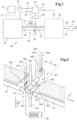
- FIG. 1 shows a block view of an installation for manufacturing a mineral wool blanket, incorporating the present invention.
- FIG 2 is a more detailed schematic view of the conveying means of the installation of the figure 1 .
- picture 3 is a sectional view according to plan III of the figure 2 .
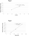
- FIG. 5 represents test results in the form of a curve giving the volume determined by the blotter method as a function of the thickness of the mattress, for a given emitter/mattress/receiver positioning.
- FIG. 6 represents test results in the form of a curve giving the volume determined by the blotter method as a function of the relative spacing between the emitter and the receiver, for a given mattress thickness.
- THE figures 7A and 7B illustrate (respectively in perspective and view along the scrolling direction X) the effective volume estimated during tests of the “blotter” type, in a given configuration.
- FIG. 1 is shown schematically an installation 100 for manufacturing fiber-based products, in particular based on a mineral wool blanket.
- the installation comprises a device 10 of known technology, allowing fiber drawing of rock or glass.
- a sizing or binder composition is sprayed onto the fibers 12 thus obtained, in a reception chamber 16, by dedicated means 18 for mixing and injecting the various constituents (resin, water, additives, etc.). Then the fibers are collected in the form of a mat or web 14, in the reception chamber 16, on a conveyor provided in its lower part with vacuum chambers maintained under vacuum (not shown).
- the fiber mat 14 is then sent by means of conveying means 20 into an oven 22, where the air temperature is for example of the order of 300° C., with a temperature at the heart of the mat around 250° C. vs.
- the mat of fibers 14' thus obtained is then transported to a unit 24 for the final preparation of the resulting products, comprising for example a cutting of the mattress so as to obtain blocks which can then be arranged in plates or rolls, and possibly the packaging of the plates or rolls thus obtained, for example their packaging in plastic film.
- the humidity in the mattress is precisely quantified upstream of the crosslinking oven 22.
- This humidity quantification is carried out by an automated device 40 described in more detail below with reference to the figure 2 And 3 , advantageously disposed at the level of the conveying means 20.
- the humidity quantification device comprises two measurement subassemblies 42c (on the left) and 42d (on the right), making it possible to quantify the humidity at the two lateral ends of the mattress.
- the invention will be described below more particularly with reference to one of these subassemblies 42c. All the corresponding description will obviously be transposable to the second subset 42d.
- the device could also comprise a greater number of sub-assemblies 42a...42n, distributed over the width of the mattress 14.
- the conveying means 20 comprise a first and a second transport member 30, 32 in the form of endless belts mounted around parallel axes, and driven by a motor.
- Each comprises a main face respectively 30a, 32a, here upper, intended to support the mat of mineral fibers 14. It could be equivalently chain conveyors or roller trains or any other suitable means of transport.
- the first and the second conveyor 30, 32 are spaced from each other, and separated, in the running direction X of the mattress, by a measurement zone 34.
- the spacing between the first transport member and the second transport member is referenced d on the figure 2 . It is typically between 10 and 30 cm.
- the fiber mat 14 is generally in the form of a continuous ribbon having two parallel main faces 14a, 14b, one of which (14b) is in contact with the conveyors 30, 32. It has a width l (including for example between 1 and 3 meters) and a thickness e (included for example between 10 and 60 centimeters), as illustrated on the picture 3 .
- a travel plane tangent to one of its main faces 14a, 14b is defined at any point of the mattress.
- a lateral direction Y is also locally defined as the direction orthogonal to the running direction X of the mattress and parallel to said running plane at the same point.
- the transmitter 44c is suitable for transmitting an incident microwave wave in the direction of the mattress.
- the receiver 46c is placed opposite the transmitter 44c. It is therefore aligned with the transmitter 44c, in a direction orthogonal to the running plane of the mattress.
- the distance Htot between transmitter and receiver is typically of the order of 50 to 100 cm, preferably between 70 and 100 cm, for example between 90 and 100 cm.
- the distance H1 between the underside of the mattress and the transmitter is for example between 0 and 10 cm.
- the receiver 46c is adapted to receive the wave transmitted at the output of the mattress and, in the example, to identify a variation of a parameter of the wave, such as a phase shift or an amplitude variation.
- the receiver 46c, the temperature sensor 50c, the humidity sensor 52c, the mattress thickness sensor 54c and the weight sensor are connected to a data processing unit 60, for example a computer, the operation of which will be described in more detail below.
- the data processing unit 60 comprises or is linked to calibration data 62, which establishes a relationship between a phase shift of the wave emitted by the transmitter 44c and/or a variation in its amplitude, and the quantity of water having acted with the wave (effective amount of water).
- the effective volume is a function of the height of the mattress and of the effective section of the mattress actually interacting with the wave.
- the height of the mattress is for example measured in real time, by a height sensor.
- the effective section of the mattress can be estimated by blotter type measurements as defined below: Starting from the above assumption that the cross section of the mattress is constant over the entire thickness of the mattress, this section can for example be determined by successively placing, between the transmitter and the receiver, plane fibrous samples - also called blotters - (plastic coated to prevent evaporation) of thickness equal to the thickness of the mattress but with increasingly larger lateral dimensions. By observing the evolution of the phase shift or the modification of the amplitude of the wave (or of any other characteristic variation), one can determine the section maximum for which there is an evolution of one of the characteristics of the wave (called cross section).
- the wave interacts with the mattress only on the portion of the sample corresponding to this effective section, but not with the rest of the sample. Although the sample is larger in size, the amount of water through which the wave passes remains the same.
- the effective volume will be estimated by considering the effective section as being variable over the thickness of the mattress.
- the cross section is estimated in a plurality of planes parallel to the main faces of the mattress: a plurality of samples are placed in layers, between the transmitter and the receiver, then the dimensions of each sample are varied gradually, one sample after another, observing each time the evolution of the phase shift or the modification of the amplitude of the wave (or of any other characteristic variation) to determine for each sample the maximum section for which there is an evolution .
- an optimal modeling of the effective volume consists of a double truncated pyramid as illustrated in the figure 4 or on the figures 7A and 7B .
- the volume depends on the thickness of the mattress on the one hand, and on the relative distance between the transmitter and the receiver and their spacing with respect to the mattress on the other hand.
- THE figures 7A and 7B give the results obtained by tests of the “blotter” type described previously, in a given line configuration.
- the transmitter and the receiver are separated by a distance Htot equal to 96 cm.
- the emitter and the receiver have useful facing surfaces which are rectangular, of width l1 equal to 92 cm (measured in the lateral direction) and of length L1 equal to 125 cm (measured in the running direction).
- the distance H1 between the underside of the mattress and the useful surface of the transmitter is equal to 10 cm.
- the volume crossed by the incident wave is approximated by a double pyramid with rectangular bases, truncated, and centered on the same transverse axis parallel to the Z axis connecting the transmitter and the receiver.
- a second truncated pyramid 82 of the same dimensions as the first pyramid, the first and the second pyramids being symmetrical with respect to their large common base.
- FIG. 5 represents test results in the form of a curve giving the volume determined by the blotter method as a function of the thickness of the mattress, for a given emitter/mattress/receiver positioning.
- the processing unit 60 comprises calculation means 64 using these calibration data, and in particular the relation (1') above, to calculate in real time, as a function of the thickness, the grammage, the temperature and ambient humidity, and variations of at least one parameter of the incident wave emitted by the transmitter 44c, the effective amount of water actually traversed by the incident wave.
- the process for quantifying the humidity in the mattress is finally carried out as follows:
- the corresponding receiver 46c, 46d acquires the signal corresponding to the transmitted wave, and determines the phase shift or the amplitude variation of the wave.
- the ambient temperature and humidity are measured by the sensors 50c, 50d; 52c, 52d.
- This information is sent to the data processing unit 60, which, using the calculation means 64, determines the effective quantity of water.
- the information on the humidity is transmitted to a control device 70 which is then capable of modifying continuously and in a very short time at least one of the parameters acting on a step of the manufacturing process. , for example via control lines 72, 74, 76.
- Said parameter can be, for example, but not limited to, the quantity of binder injected, the initial composition of the mixture and in particular the quantity of water present with the resin (line of command 72), the temperature of the oven or the time spent in the oven (line 76), the speed or air flow of the oven, etc...
- the presence of two measuring sub-assemblies 42c, 42d makes it possible to determine a right/left humidity difference in the mattress, and thus to evaluate the homogeneity of the production.
- the two subassemblies are perfectly symmetrical with respect to a median plane of the mattress.
- the distance between the receivers 46c, 46d is advantageously identical to that d2 separating the two transmitters 44c, 44d.
- the distance d2 separating the two transmitters 44c, 44d is chosen so as to avoid interference between the waves emanating from each transmitter (distance d3 between the effective volumes of the subsets 42c, 42d greater than 0, see figures 3 or 4 ).
Landscapes
- Physics & Mathematics (AREA)
- Electromagnetism (AREA)
- Health & Medical Sciences (AREA)
- Life Sciences & Earth Sciences (AREA)
- Chemical & Material Sciences (AREA)
- Analytical Chemistry (AREA)
- Biochemistry (AREA)
- General Health & Medical Sciences (AREA)
- General Physics & Mathematics (AREA)
- Immunology (AREA)
- Pathology (AREA)
- Treatment Of Fiber Materials (AREA)
- Investigating Or Analyzing Non-Biological Materials By The Use Of Chemical Means (AREA)
- Investigating Or Analyzing Materials Using Thermal Means (AREA)
- Investigating Or Analysing Materials By Optical Means (AREA)
- Paper (AREA)
Applications Claiming Priority (2)
| Application Number | Priority Date | Filing Date | Title |
|---|---|---|---|
| FR1770753A FR3069056B1 (fr) | 2017-07-13 | 2017-07-13 | Procede de quantification de l'humidite dans un matelas de fibres |
| PCT/FR2018/051766 WO2019012232A1 (fr) | 2017-07-13 | 2018-07-12 | Procede de quantification de l'humidite dans un matelas de fibres |
Publications (3)
| Publication Number | Publication Date |
|---|---|
| EP3652525A1 EP3652525A1 (fr) | 2020-05-20 |
| EP3652525B1 true EP3652525B1 (fr) | 2023-07-05 |
| EP3652525C0 EP3652525C0 (fr) | 2023-07-05 |
Family
ID=59930640
Family Applications (1)
| Application Number | Title | Priority Date | Filing Date |
|---|---|---|---|
| EP18749041.2A Active EP3652525B1 (fr) | 2017-07-13 | 2018-07-12 | Procede de quantification de l'humidite dans un matelas de fibres |
Country Status (6)
| Country | Link |
|---|---|
| US (1) | US11353408B2 (pl) |
| EP (1) | EP3652525B1 (pl) |
| ES (1) | ES2954293T3 (pl) |
| FR (1) | FR3069056B1 (pl) |
| PL (1) | PL3652525T3 (pl) |
| WO (1) | WO2019012232A1 (pl) |
Families Citing this family (1)
| Publication number | Priority date | Publication date | Assignee | Title |
|---|---|---|---|---|
| TWI837976B (zh) * | 2021-10-20 | 2024-04-01 | 桓達科技股份有限公司 | 取得耦合微波感測器的訊號值與物體含水率的線性回歸式的方法 |
Family Cites Families (10)
| Publication number | Priority date | Publication date | Assignee | Title |
|---|---|---|---|---|
| DE19805584C2 (de) * | 1998-02-12 | 2000-04-13 | Daimler Chrysler Ag | System und Verfahren zur Materialüberprüfung von Werkstoffen, sowie Werkstoff und Verfahren zu seiner Herstellung |
| EP1107914A1 (en) * | 1998-06-29 | 2001-06-20 | UPM-Kymmene Corporation | Method for closing a liquid packaging container |
| US7129834B2 (en) * | 2002-03-28 | 2006-10-31 | Kabushiki Kaisha Toshiba | String wireless sensor and its manufacturing method |
| US7435444B2 (en) * | 2004-07-23 | 2008-10-14 | Johns Manville | Control of pre-cured product moisture for formaldehyde-free fiberglass products |
| US20120144868A1 (en) * | 2010-12-09 | 2012-06-14 | Owens Corning Intellectual Capital, Llc | Apparatus and method for controlling moisture in the manufacture of glass fiber insulation |
| US9058455B2 (en) * | 2012-01-20 | 2015-06-16 | International Business Machines Corporation | Backside integration of RF filters for RF front end modules and design structure |
| US10179064B2 (en) * | 2014-05-09 | 2019-01-15 | Sleepnea Llc | WhipFlash [TM]: wearable environmental control system for predicting and cooling hot flashes |
| GB2563712B (en) * | 2015-08-23 | 2021-07-14 | Newham Paul | Modular systems for monitoring the presence of a person using a variety of sensing and connection devices |
| US20180283171A1 (en) * | 2015-12-22 | 2018-10-04 | Halliburton Energy Services, Inc | System And Method For Optical Communication Using Optical Switches |
| JPWO2018003936A1 (ja) * | 2016-06-30 | 2019-04-18 | 株式会社クラレ | キャパシタ用セパレータ |
-
2017
- 2017-07-13 FR FR1770753A patent/FR3069056B1/fr active Active
-
2018
- 2018-07-12 WO PCT/FR2018/051766 patent/WO2019012232A1/fr not_active Ceased
- 2018-07-12 ES ES18749041T patent/ES2954293T3/es active Active
- 2018-07-12 US US16/630,244 patent/US11353408B2/en active Active
- 2018-07-12 PL PL18749041.2T patent/PL3652525T3/pl unknown
- 2018-07-12 EP EP18749041.2A patent/EP3652525B1/fr active Active
Also Published As
| Publication number | Publication date |
|---|---|
| FR3069056A1 (fr) | 2019-01-18 |
| US20210096087A1 (en) | 2021-04-01 |
| EP3652525A1 (fr) | 2020-05-20 |
| WO2019012232A1 (fr) | 2019-01-17 |
| PL3652525T3 (pl) | 2023-09-04 |
| ES2954293T3 (es) | 2023-11-21 |
| EP3652525C0 (fr) | 2023-07-05 |
| US11353408B2 (en) | 2022-06-07 |
| FR3069056B1 (fr) | 2020-09-25 |
Similar Documents
| Publication | Publication Date | Title |
|---|---|---|
| WO2007128942A1 (fr) | Methode de detection des defauts localises presents dans un matelas de fibres minerales | |
| JP5923237B2 (ja) | 煙草加工産業のフィルタのカプセル監視とカプセル位置調整 | |
| KR20190015192A (ko) | 주조 장치 및 캐스트 시트의 두께를 검사하는 방법 | |
| EP2587253B1 (en) | Method and device for online measurement of plasticizer content in an endless filter rod | |
| CN1635840A (zh) | 香烟工业中用于同时连续地测定和控制过滤嘴杆内的醋酸纤维素和甘油三乙酸酯的含量的装置 | |
| CA1268110A (fr) | Enrouleuse a compression asservie | |
| GB2489587A (en) | Method and system for producing an endless filter rod | |
| EP4084633B1 (en) | Method and apparatus to crimp a sheet | |
| EP0118369B1 (fr) | Perfectionnements aux techniques de formation de feutres de fibres | |
| CN108291881B (zh) | 用于确定添加剂份额的设备和方法以及烟草加工业的机器 | |
| EP3652525A1 (fr) | Procede de quantification de l'humidite dans un matelas de fibres | |
| EP3240922A1 (fr) | Procédé de mesure à l'intérieur d'un matelas de fibres minérales ou végétales | |
| EP2943606B1 (fr) | Produit d'isolation thermique a base de laine minerale et procede de fabrication du produit | |
| CA3008533C (fr) | Produit d'isolation comprenant de la laine minerale en vrac | |
| WO2019073020A1 (fr) | Panneau acoustique en laine minerale et procede de fabrication d'un tel panneau | |
| EP4188684B1 (fr) | Etuve munie d'un systeme de mesure a l'interieur du matelas fibreux | |
| EP3898547B1 (fr) | Procede d'ajustement de la quantite d'eau de dilution d'une composition d'encollage, et unite de calcul correspondante | |
| JP2024071726A (ja) | アルカロイドを含有する材料のウェブをキャストするための方法および装置 | |
| EP3472380B1 (fr) | Installation de traitement d'un matelas de fibres minerales par detection et evacuation de defauts localises, et procede correspondant | |
| EP3429791B1 (fr) | Procede de decoupe d'un matelas, d'un panneau ou d'une plaque en laine minerale ou materiau de construction poreux | |
| RU2812695C1 (ru) | Способ и установка для гофрирования листа | |
| US20260033528A1 (en) | Method and apparatus for splicing two sheets of material | |
| FR2529878A1 (fr) | Perfectionnements aux techniques de formation de fibres comprenant une centrifugation |
Legal Events
| Date | Code | Title | Description |
|---|---|---|---|
| STAA | Information on the status of an ep patent application or granted ep patent |
Free format text: STATUS: UNKNOWN |
|
| STAA | Information on the status of an ep patent application or granted ep patent |
Free format text: STATUS: THE INTERNATIONAL PUBLICATION HAS BEEN MADE |
|
| PUAI | Public reference made under article 153(3) epc to a published international application that has entered the european phase |
Free format text: ORIGINAL CODE: 0009012 |
|
| STAA | Information on the status of an ep patent application or granted ep patent |
Free format text: STATUS: REQUEST FOR EXAMINATION WAS MADE |
|
| 17P | Request for examination filed |
Effective date: 20200213 |
|
| AK | Designated contracting states |
Kind code of ref document: A1 Designated state(s): AL AT BE BG CH CY CZ DE DK EE ES FI FR GB GR HR HU IE IS IT LI LT LU LV MC MK MT NL NO PL PT RO RS SE SI SK SM TR |
|
| AX | Request for extension of the european patent |
Extension state: BA ME |
|
| RAP1 | Party data changed (applicant data changed or rights of an application transferred) |
Owner name: SAINT-GOBAIN ISOVER |
|
| DAV | Request for validation of the european patent (deleted) | ||
| DAX | Request for extension of the european patent (deleted) | ||
| STAA | Information on the status of an ep patent application or granted ep patent |
Free format text: STATUS: EXAMINATION IS IN PROGRESS |
|
| 17Q | First examination report despatched |
Effective date: 20211122 |
|
| GRAP | Despatch of communication of intention to grant a patent |
Free format text: ORIGINAL CODE: EPIDOSNIGR1 |
|
| STAA | Information on the status of an ep patent application or granted ep patent |
Free format text: STATUS: GRANT OF PATENT IS INTENDED |
|
| INTG | Intention to grant announced |
Effective date: 20220922 |
|
| RIN1 | Information on inventor provided before grant (corrected) |
Inventor name: GAUBIL, MICHEL Inventor name: COSSALTER, LAURE Inventor name: SOTERAS, FIONA Inventor name: ROUBIN, MARC Inventor name: D'HERIN BYTNER, FREDERIC |
|
| GRAJ | Information related to disapproval of communication of intention to grant by the applicant or resumption of examination proceedings by the epo deleted |
Free format text: ORIGINAL CODE: EPIDOSDIGR1 |
|
| STAA | Information on the status of an ep patent application or granted ep patent |
Free format text: STATUS: EXAMINATION IS IN PROGRESS |
|
| GRAP | Despatch of communication of intention to grant a patent |
Free format text: ORIGINAL CODE: EPIDOSNIGR1 |
|
| STAA | Information on the status of an ep patent application or granted ep patent |
Free format text: STATUS: GRANT OF PATENT IS INTENDED |
|
| INTC | Intention to grant announced (deleted) | ||
| INTG | Intention to grant announced |
Effective date: 20230206 |
|
| GRAS | Grant fee paid |
Free format text: ORIGINAL CODE: EPIDOSNIGR3 |
|
| GRAA | (expected) grant |
Free format text: ORIGINAL CODE: 0009210 |
|
| STAA | Information on the status of an ep patent application or granted ep patent |
Free format text: STATUS: THE PATENT HAS BEEN GRANTED |
|
| AK | Designated contracting states |
Kind code of ref document: B1 Designated state(s): AL AT BE BG CH CY CZ DE DK EE ES FI FR GB GR HR HU IE IS IT LI LT LU LV MC MK MT NL NO PL PT RO RS SE SI SK SM TR |
|
| REG | Reference to a national code |
Ref country code: CH Ref legal event code: EP |
|
| REG | Reference to a national code |
Ref country code: AT Ref legal event code: REF Ref document number: 1585283 Country of ref document: AT Kind code of ref document: T Effective date: 20230715 |
|
| REG | Reference to a national code |
Ref country code: DE Ref legal event code: R096 Ref document number: 602018052850 Country of ref document: DE |
|
| REG | Reference to a national code |
Ref country code: IE Ref legal event code: FG4D Free format text: LANGUAGE OF EP DOCUMENT: FRENCH |
|
| U01 | Request for unitary effect filed |
Effective date: 20230705 |
|
| U07 | Unitary effect registered |
Designated state(s): AT BE BG DE DK EE FI FR IT LT LU LV MT NL PT SE SI Effective date: 20230710 |
|
| REG | Reference to a national code |
Ref country code: RO Ref legal event code: EPE |
|
| REG | Reference to a national code |
Ref country code: NO Ref legal event code: T2 Effective date: 20230705 |
|
| REG | Reference to a national code |
Ref country code: LT Ref legal event code: MG9D |
|
| REG | Reference to a national code |
Ref country code: ES Ref legal event code: FG2A Ref document number: 2954293 Country of ref document: ES Kind code of ref document: T3 Effective date: 20231121 |
|
| U20 | Renewal fee for the european patent with unitary effect paid |
Year of fee payment: 6 Effective date: 20231020 |
|
| PG25 | Lapsed in a contracting state [announced via postgrant information from national office to epo] |
Ref country code: GR Free format text: LAPSE BECAUSE OF FAILURE TO SUBMIT A TRANSLATION OF THE DESCRIPTION OR TO PAY THE FEE WITHIN THE PRESCRIBED TIME-LIMIT Effective date: 20231006 |
|
| PG25 | Lapsed in a contracting state [announced via postgrant information from national office to epo] |
Ref country code: IS Free format text: LAPSE BECAUSE OF FAILURE TO SUBMIT A TRANSLATION OF THE DESCRIPTION OR TO PAY THE FEE WITHIN THE PRESCRIBED TIME-LIMIT Effective date: 20231105 |
|
| PG25 | Lapsed in a contracting state [announced via postgrant information from national office to epo] |
Ref country code: RS Free format text: LAPSE BECAUSE OF FAILURE TO SUBMIT A TRANSLATION OF THE DESCRIPTION OR TO PAY THE FEE WITHIN THE PRESCRIBED TIME-LIMIT Effective date: 20230705 Ref country code: IS Free format text: LAPSE BECAUSE OF FAILURE TO SUBMIT A TRANSLATION OF THE DESCRIPTION OR TO PAY THE FEE WITHIN THE PRESCRIBED TIME-LIMIT Effective date: 20231105 Ref country code: HR Free format text: LAPSE BECAUSE OF FAILURE TO SUBMIT A TRANSLATION OF THE DESCRIPTION OR TO PAY THE FEE WITHIN THE PRESCRIBED TIME-LIMIT Effective date: 20230705 Ref country code: GR Free format text: LAPSE BECAUSE OF FAILURE TO SUBMIT A TRANSLATION OF THE DESCRIPTION OR TO PAY THE FEE WITHIN THE PRESCRIBED TIME-LIMIT Effective date: 20231006 |
|
| REG | Reference to a national code |
Ref country code: DE Ref legal event code: R097 Ref document number: 602018052850 Country of ref document: DE |
|
| REG | Reference to a national code |
Ref country code: IE Ref legal event code: MM4A |
|
| PG25 | Lapsed in a contracting state [announced via postgrant information from national office to epo] |
Ref country code: SM Free format text: LAPSE BECAUSE OF FAILURE TO SUBMIT A TRANSLATION OF THE DESCRIPTION OR TO PAY THE FEE WITHIN THE PRESCRIBED TIME-LIMIT Effective date: 20230705 Ref country code: MC Free format text: LAPSE BECAUSE OF FAILURE TO SUBMIT A TRANSLATION OF THE DESCRIPTION OR TO PAY THE FEE WITHIN THE PRESCRIBED TIME-LIMIT Effective date: 20230705 Ref country code: SK Free format text: LAPSE BECAUSE OF FAILURE TO SUBMIT A TRANSLATION OF THE DESCRIPTION OR TO PAY THE FEE WITHIN THE PRESCRIBED TIME-LIMIT Effective date: 20230705 |
|
| PLBE | No opposition filed within time limit |
Free format text: ORIGINAL CODE: 0009261 |
|
| STAA | Information on the status of an ep patent application or granted ep patent |
Free format text: STATUS: NO OPPOSITION FILED WITHIN TIME LIMIT |
|
| 26N | No opposition filed |
Effective date: 20240408 |
|
| PG25 | Lapsed in a contracting state [announced via postgrant information from national office to epo] |
Ref country code: IE Free format text: LAPSE BECAUSE OF NON-PAYMENT OF DUE FEES Effective date: 20230712 |
|
| PG25 | Lapsed in a contracting state [announced via postgrant information from national office to epo] |
Ref country code: IE Free format text: LAPSE BECAUSE OF NON-PAYMENT OF DUE FEES Effective date: 20230712 |
|
| U20 | Renewal fee for the european patent with unitary effect paid |
Year of fee payment: 7 Effective date: 20240731 |
|
| U1N | Appointed representative for the unitary patent procedure changed after the registration of the unitary effect |
Representative=s name: SAINT-GOBAIN RECHERCHE; FR |
|
| PGFP | Annual fee paid to national office [announced via postgrant information from national office to epo] |
Ref country code: PL Payment date: 20250608 Year of fee payment: 8 |
|
| PGFP | Annual fee paid to national office [announced via postgrant information from national office to epo] |
Ref country code: GB Payment date: 20250529 Year of fee payment: 8 |
|
| U20 | Renewal fee for the european patent with unitary effect paid |
Year of fee payment: 8 Effective date: 20250606 |
|
| PGFP | Annual fee paid to national office [announced via postgrant information from national office to epo] |
Ref country code: RO Payment date: 20250619 Year of fee payment: 8 |
|
| PG25 | Lapsed in a contracting state [announced via postgrant information from national office to epo] |
Ref country code: CY Free format text: LAPSE BECAUSE OF FAILURE TO SUBMIT A TRANSLATION OF THE DESCRIPTION OR TO PAY THE FEE WITHIN THE PRESCRIBED TIME-LIMIT; INVALID AB INITIO Effective date: 20180712 |
|
| PGFP | Annual fee paid to national office [announced via postgrant information from national office to epo] |
Ref country code: CZ Payment date: 20250618 Year of fee payment: 8 |
|
| PG25 | Lapsed in a contracting state [announced via postgrant information from national office to epo] |
Ref country code: HU Free format text: LAPSE BECAUSE OF FAILURE TO SUBMIT A TRANSLATION OF THE DESCRIPTION OR TO PAY THE FEE WITHIN THE PRESCRIBED TIME-LIMIT; INVALID AB INITIO Effective date: 20180712 |
|
| PGFP | Annual fee paid to national office [announced via postgrant information from national office to epo] |
Ref country code: ES Payment date: 20250804 Year of fee payment: 8 |
|
| PGFP | Annual fee paid to national office [announced via postgrant information from national office to epo] |
Ref country code: NO Payment date: 20250709 Year of fee payment: 8 |
|
| PGFP | Annual fee paid to national office [announced via postgrant information from national office to epo] |
Ref country code: TR Payment date: 20250703 Year of fee payment: 8 |
|
| PGFP | Annual fee paid to national office [announced via postgrant information from national office to epo] |
Ref country code: CH Payment date: 20250801 Year of fee payment: 8 |