EP3652402B1 - Furniture damper - Google Patents
Furniture damper Download PDFInfo
- Publication number
- EP3652402B1 EP3652402B1 EP18737142.2A EP18737142A EP3652402B1 EP 3652402 B1 EP3652402 B1 EP 3652402B1 EP 18737142 A EP18737142 A EP 18737142A EP 3652402 B1 EP3652402 B1 EP 3652402B1
- Authority
- EP
- European Patent Office
- Prior art keywords
- piston
- furniture
- closure element
- fitting according
- fluid
- Prior art date
- Legal status (The legal status is an assumption and is not a legal conclusion. Google has not performed a legal analysis and makes no representation as to the accuracy of the status listed.)
- Active
Links
- 239000012530 fluid Substances 0.000 claims description 77
- 238000013016 damping Methods 0.000 claims description 66
- 230000000087 stabilizing effect Effects 0.000 claims description 12
- 230000006835 compression Effects 0.000 claims description 7
- 238000007906 compression Methods 0.000 claims description 7
- 230000001419 dependent effect Effects 0.000 description 3
- 239000006096 absorbing agent Substances 0.000 description 2
- 230000000694 effects Effects 0.000 description 2
- 238000004146 energy storage Methods 0.000 description 2
- 230000010355 oscillation Effects 0.000 description 2
- 230000035939 shock Effects 0.000 description 2
- 238000005452 bending Methods 0.000 description 1
- 230000009172 bursting Effects 0.000 description 1
- 230000008878 coupling Effects 0.000 description 1
- 238000010168 coupling process Methods 0.000 description 1
- 238000005859 coupling reaction Methods 0.000 description 1
- 229920001821 foam rubber Polymers 0.000 description 1
- 238000009434 installation Methods 0.000 description 1
- 239000002655 kraft paper Substances 0.000 description 1
- 238000004519 manufacturing process Methods 0.000 description 1
- 239000000463 material Substances 0.000 description 1
- 230000002093 peripheral effect Effects 0.000 description 1
- 239000007787 solid Substances 0.000 description 1
Images


Classifications
-
- A—HUMAN NECESSITIES
- A47—FURNITURE; DOMESTIC ARTICLES OR APPLIANCES; COFFEE MILLS; SPICE MILLS; SUCTION CLEANERS IN GENERAL
- A47B—TABLES; DESKS; OFFICE FURNITURE; CABINETS; DRAWERS; GENERAL DETAILS OF FURNITURE
- A47B88/00—Drawers for tables, cabinets or like furniture; Guides for drawers
- A47B88/40—Sliding drawers; Slides or guides therefor
- A47B88/473—Braking devices, e.g. linear or rotational dampers or friction brakes; Buffers; End stops
- A47B88/477—Buffers; End stops
-
- F—MECHANICAL ENGINEERING; LIGHTING; HEATING; WEAPONS; BLASTING
- F16—ENGINEERING ELEMENTS AND UNITS; GENERAL MEASURES FOR PRODUCING AND MAINTAINING EFFECTIVE FUNCTIONING OF MACHINES OR INSTALLATIONS; THERMAL INSULATION IN GENERAL
- F16F—SPRINGS; SHOCK-ABSORBERS; MEANS FOR DAMPING VIBRATION
- F16F9/00—Springs, vibration-dampers, shock-absorbers, or similarly-constructed movement-dampers using a fluid or the equivalent as damping medium
- F16F9/32—Details
- F16F9/50—Special means providing automatic damping adjustment, i.e. self-adjustment of damping by particular sliding movements of a valve element, other than flexions or displacement of valve discs; Special means providing self-adjustment of spring characteristics
- F16F9/512—Means responsive to load action, i.e. static load on the damper or dynamic fluid pressure changes in the damper, e.g. due to changes in velocity
-
- E—FIXED CONSTRUCTIONS
- E05—LOCKS; KEYS; WINDOW OR DOOR FITTINGS; SAFES
- E05F—DEVICES FOR MOVING WINGS INTO OPEN OR CLOSED POSITION; CHECKS FOR WINGS; WING FITTINGS NOT OTHERWISE PROVIDED FOR, CONCERNED WITH THE FUNCTIONING OF THE WING
- E05F5/00—Braking devices, e.g. checks; Stops; Buffers
- E05F5/02—Braking devices, e.g. checks; Stops; Buffers specially for preventing the slamming of swinging wings during final closing movement, e.g. jamb stops
-
- A—HUMAN NECESSITIES
- A47—FURNITURE; DOMESTIC ARTICLES OR APPLIANCES; COFFEE MILLS; SPICE MILLS; SUCTION CLEANERS IN GENERAL
- A47B—TABLES; DESKS; OFFICE FURNITURE; CABINETS; DRAWERS; GENERAL DETAILS OF FURNITURE
- A47B88/00—Drawers for tables, cabinets or like furniture; Guides for drawers
- A47B88/40—Sliding drawers; Slides or guides therefor
- A47B88/473—Braking devices, e.g. linear or rotational dampers or friction brakes; Buffers; End stops
-
- E—FIXED CONSTRUCTIONS
- E05—LOCKS; KEYS; WINDOW OR DOOR FITTINGS; SAFES
- E05F—DEVICES FOR MOVING WINGS INTO OPEN OR CLOSED POSITION; CHECKS FOR WINGS; WING FITTINGS NOT OTHERWISE PROVIDED FOR, CONCERNED WITH THE FUNCTIONING OF THE WING
- E05F5/00—Braking devices, e.g. checks; Stops; Buffers
- E05F5/003—Braking devices, e.g. checks; Stops; Buffers for sliding wings
-
- E—FIXED CONSTRUCTIONS
- E05—LOCKS; KEYS; WINDOW OR DOOR FITTINGS; SAFES
- E05F—DEVICES FOR MOVING WINGS INTO OPEN OR CLOSED POSITION; CHECKS FOR WINGS; WING FITTINGS NOT OTHERWISE PROVIDED FOR, CONCERNED WITH THE FUNCTIONING OF THE WING
- E05F5/00—Braking devices, e.g. checks; Stops; Buffers
- E05F5/06—Buffers or stops limiting opening of swinging wings, e.g. floor or wall stops
- E05F5/10—Buffers or stops limiting opening of swinging wings, e.g. floor or wall stops with piston brakes
-
- F—MECHANICAL ENGINEERING; LIGHTING; HEATING; WEAPONS; BLASTING
- F16—ENGINEERING ELEMENTS AND UNITS; GENERAL MEASURES FOR PRODUCING AND MAINTAINING EFFECTIVE FUNCTIONING OF MACHINES OR INSTALLATIONS; THERMAL INSULATION IN GENERAL
- F16F—SPRINGS; SHOCK-ABSORBERS; MEANS FOR DAMPING VIBRATION
- F16F9/00—Springs, vibration-dampers, shock-absorbers, or similarly-constructed movement-dampers using a fluid or the equivalent as damping medium
- F16F9/32—Details
- F16F9/34—Special valve constructions; Shape or construction of throttling passages
-
- F—MECHANICAL ENGINEERING; LIGHTING; HEATING; WEAPONS; BLASTING
- F16—ENGINEERING ELEMENTS AND UNITS; GENERAL MEASURES FOR PRODUCING AND MAINTAINING EFFECTIVE FUNCTIONING OF MACHINES OR INSTALLATIONS; THERMAL INSULATION IN GENERAL
- F16F—SPRINGS; SHOCK-ABSORBERS; MEANS FOR DAMPING VIBRATION
- F16F9/00—Springs, vibration-dampers, shock-absorbers, or similarly-constructed movement-dampers using a fluid or the equivalent as damping medium
- F16F9/32—Details
- F16F9/50—Special means providing automatic damping adjustment, i.e. self-adjustment of damping by particular sliding movements of a valve element, other than flexions or displacement of valve discs; Special means providing self-adjustment of spring characteristics
- F16F9/516—Special means providing automatic damping adjustment, i.e. self-adjustment of damping by particular sliding movements of a valve element, other than flexions or displacement of valve discs; Special means providing self-adjustment of spring characteristics resulting in the damping effects during contraction being different from the damping effects during extension, i.e. responsive to the direction of movement
-
- E—FIXED CONSTRUCTIONS
- E05—LOCKS; KEYS; WINDOW OR DOOR FITTINGS; SAFES
- E05Y—INDEXING SCHEME RELATING TO HINGES OR OTHER SUSPENSION DEVICES FOR DOORS, WINDOWS OR WINGS AND DEVICES FOR MOVING WINGS INTO OPEN OR CLOSED POSITION, CHECKS FOR WINGS AND WING FITTINGS NOT OTHERWISE PROVIDED FOR, CONCERNED WITH THE FUNCTIONING OF THE WING
- E05Y2900/00—Application of doors, windows, wings or fittings thereof
- E05Y2900/20—Application of doors, windows, wings or fittings thereof for furnitures, e.g. cabinets
-
- F—MECHANICAL ENGINEERING; LIGHTING; HEATING; WEAPONS; BLASTING
- F16—ENGINEERING ELEMENTS AND UNITS; GENERAL MEASURES FOR PRODUCING AND MAINTAINING EFFECTIVE FUNCTIONING OF MACHINES OR INSTALLATIONS; THERMAL INSULATION IN GENERAL
- F16F—SPRINGS; SHOCK-ABSORBERS; MEANS FOR DAMPING VIBRATION
- F16F9/00—Springs, vibration-dampers, shock-absorbers, or similarly-constructed movement-dampers using a fluid or the equivalent as damping medium
- F16F9/32—Details
- F16F9/34—Special valve constructions; Shape or construction of throttling passages
- F16F9/3405—Throttling passages in or on piston body, e.g. slots
Definitions
- non-generic prior art is shown in the form of a shock absorber for vehicles, the shock absorber having an overload protection with a valve body acted upon by a spring.
- the valve body is provided with a passage opening so that the damping fluid can flow from the high pressure side to the low pressure side.
- General furniture dampers for damping movably mounted furniture parts are available in the WO 03/081077 A1 , in the WO 2006/029421 A1 , in the DE 201 07 426 U1 , in the AT 12 633 U1 and in the DE 20 2008 002 407 U1 shown.
- the document FR 2 594 473 A1 discloses a furniture fitting with at least one furniture damper according to the preamble of claim 1.
- Furniture fittings with a furniture damper are used, for example, to dampen a closing movement of movable furniture parts (drawers, doors or flaps) or of movably mounted furniture fittings, so that loud slamming and damage to the furniture parts are prevented.
- the damping effect of furniture dampers is generated by the flow resistance of a damping fluid located in a housing.
- the piston When pressure is applied, the piston is displaced within the fluid chamber, with the damping fluid flowing from the high-pressure side to the low-pressure side through piston openings and/or through a gap formed between the piston and the inner wall of the fluid chamber. If the piston is subjected to too much pressure, for example due to improper use, so-called damper bounce can occur. In such an overload case, the damping fluid can no longer flow sufficiently through the piston or past the piston. The increased pressure can then no longer be reduced by the damper, so that the piston or the piston rod attached to it stops abruptly or springs back.
- Overload protection for furniture dampers is widely known, for example from AT 12 633 U1 the applicant.
- These overload protection devices usually have a ball acted upon by a spring, which closes an overload opening of the piston in normal operation (ie below a predetermined pressurization on the piston) and which closes the overload opening of the piston in an overload case (ie above the predetermined pressurization on the piston). against the force of the energy accumulator, whereby a fluid-conducting connection between the high-pressure side and the low-pressure side is released. By releasing this fluid-conducting connection, a larger amount of Damping fluid is transported from the high-pressure side to the low-pressure side, so that the pressure in the furniture damper is quickly reduced and the housing of the furniture damper is prevented from bursting open.
- a path-dependent control of the damping force can be achieved through flow channels arranged on the inner wall of the cylinder.
- the flow channels can be designed in such a way that the effective flow cross section is reduced along the damping stroke ( DE 20 2008 002 407 U1 , Fig. 7). In this way, the further the piston is pushed into the cylinder, the higher the flow resistance of the damping fluid and thus the damping force.
- the disadvantage of this is that the production of such flow channels is relatively complex and that the installation space of the furniture damper increases accordingly.
- the object of the present invention is to provide a furniture fitting of the type mentioned at the beginning while avoiding the disadvantages discussed above, whereby in addition to a compact design, load-safe operation of the furniture damper is also made possible.
- the closure element has at least one throttle opening for the passage of the damping fluid from the high-pressure side to the low-pressure side, at least when executing the damping stroke.
- the closure element for closing the overload opening arranged in the piston has at least one throttle opening through which the damping fluid can flow even during a damping stroke carried out in normal operation (ie below the predetermined threshold value of pressurization on the piston).
- a throttle opening By arranging such a throttle opening, at least part of the braking force can be generated without there being an absolute need to arrange additional flow channels in the piston and/or on the inner wall of the fluid chamber.
- additional flow channels can also be provided in addition to the throttle opening of the closure element.
- the throttle opening is open in every operating position of the furniture damper. This allows the damping fluid to flow through the throttle opening of the closure element both when executing the damping stroke and when executing the return stroke.
- the damping fluid can be gaseous or hydraulic.
- the closure element has a cylindrical and / or a conical lateral surface and that the damping fluid above the predetermined threshold value of the pressurization on the piston downstream of the overload opening through the fluid-conducting connection in an axial direction along the cylindrical and / or conical
- the lateral surface of the closure element is guided past or directed away in a radial direction from the cylindrical and / or conical lateral surface of the closure element.
- the damping fluid is deflected in the event of an overload in such a way that a dynamic pressure in an area located behind (i.e. downstream) the closure element is prevented or at least reduced in such a way that the dynamic pressure behind the closure element is lower than that in front of it Fluid pressure occurring in the closure element is.
- This measure ensures that the closure element has a defined switching behavior, so that oscillation of the closure element in a longitudinal direction of the piston and the associated bouncing of a piston rod in the event of an overload is prevented.
- the closure element is mounted so that it can move to a limited extent relative to the piston in a longitudinal direction of the piston.
- the closure element can, for example, be designed as a solid body. According to an alternative embodiment, the closure element can also be designed as a hollow body, for example as a sleeve.
- the cavity of the closure element can be designed to at least partially accommodate the energy accumulator, which results in a very compact design.
- Fig. 1 shows a piece of furniture 1 with a cabinet-shaped furniture body 2, with movable furniture parts 3 in the form of drawers being mounted so that they can move relative to the furniture body 2 via drawer pull-out guides 4.
- the drawers each have a front panel 5, a drawer bottom 6, drawer side walls 7 and a rear wall 8.
- the drawer pull-out guides 4 each include a body rail 9, which is to be attached to the furniture body 2 via fastening sections 12a, 12b, a drawer rail 10 which is displaceably mounted relative to the body rail 9 and which is connected or is to be connected to the drawer side wall 7, as well as optionally a middle rail 11, which is movably mounted between the body rail 9 and the drawer rail 10 in order to fully extend the drawer.
- Fig. 2 shows a drawer pull-out guide 4 and a drawer side wall 7 to be connected to the drawer rail 10 in a perspective view.
- a movable middle rail 11 is arranged between the drawer rail 10 and the body rail 9, a coupling element 13 being arranged on the drawer rail 10, which can be releasably coupled to a spring-loaded driver 14 of a retraction device 15, so that the drawer rail 10 is detached from the driver 14 towards the end of the closing movement detected and can be retracted into a closed end position by an energy storage device of the retraction device 15.
- This spring-supported retraction movement of the drawer rail 10 can be braked up to the closed end position by a furniture damper 16, which is still to be described, with a, preferably hydraulic, piston-cylinder unit.
- the drawer side wall 7 is designed as a hollow chamber profile with an inner profile wall 7a and an outer profile wall 7b, the drawer side wall 7 having a channel 17 which is open towards the bottom and extends in the longitudinal direction of the drawer side wall 7 for receiving the drawer rail 10.
- the drawer side wall 7 also has a first fastening device 38a for connecting to the rear wall 8, a second fastening device 38b for connecting to the front panel 5 and a support 18 for supporting the drawer bottom 6.
- Fig. 3a shows the furniture damper 16 in an exploded view.
- the furniture damper 16 has a, for example cylindrical, housing 19, in which a fluid chamber 19a is formed for the displaceable mounting of a piston 20.
- the piston 20 is connected to a piston rod 21 led out of the housing 19, the piston 20 being mounted displaceably within the fluid chamber 19a in a longitudinal direction (L) of the piston rod 21 between a first end position and a second end position.
- L longitudinal direction
- the piston 20 is preferably against the resistance of a piston located in the housing 19 hydraulic damping fluid can be braked.
- the piston 20 can be made in one piece or in several parts.
- a volume of the fluid chamber 19a can be changed, with a deformable or movable compensation device 23 being provided to compensate for the volume of the fluid chamber 19a.
- a stabilizing element 24 with an opening 24a for displaceably receiving the piston rod 21 is arranged, so that the piston rod 21 when executing the damping stroke in a transverse to the longitudinal direction (L) the piston rod 21 can be stabilized in the direction extending.
- the piston rod 21 is precisely guided in the longitudinal direction (L), preventing bending or buckling of the piston rod 21 when moving in the longitudinal direction (L).
- a closure part 22 is provided for fluid-tight closure of the fluid chamber 19a.
- Fig. 3b shows the in Fig. 3a circled area (A) in an enlarged view.
- the compensation device 23 can either comprise a compressible piece of material (for example foam rubber) or alternatively - as shown in the figure - a seal 23c which can be acted upon by a compression spring 23a and which is mounted displaceably along the piston rod 21 within the fluid chamber 19a.
- the seal 23c can be supported on a bearing part 23b relative to the compression spring 23a.
- the size of the opening 24a of the, preferably disk-shaped, stabilizing element 24 essentially corresponds to a diameter of the piston rod 21.
- the stabilizing element 24 rests at least partially on an inner wall of the fluid chamber 19a and has at least one, preferably peripheral, recess 26a for the passage of the fluid chamber 19a arranged damping fluid.
- the stabilizing element 24 is provided with two or more recesses 26a, 26b, 26c for the passage of the damping fluid.
- the stabilizing element 24 can be mounted within the fluid chamber 19a in an area spaced between the two end positions of the piston 20 either in a fixed manner or with limited movement in the longitudinal direction (L).
- Fig. 3c shows the in Fig. 3a circled area (B) in an enlarged view.
- the piston 20 has two interconnected piston parts 20c, 20d and an overload protection 25 with a closure element 20b, the closure element 20b being acted upon by a force accumulator 20a in the form of a compression spring.
- the closure element 20b can have a cylindrical lateral surface 33a and/or a conical lateral surface 33b.
- the damping fluid can flow through the closure element 20b through at least one throttle opening 32 of the closure element 20b.
- the piston 20 is provided with at least one overload opening 30 ( Fig. 4b ), which is closed by the closure element 20b below a predetermined pressure on the piston 20.
- the closure element 20b is moved against the force of the energy accumulator 20a, so that the overload opening 30 of the piston 20 is released for the passage of the damping fluid in the event of an overload.
- a rapid pressure reduction in the fluid chamber 19a is brought about without the housing 19, the piston 20 or another component of the furniture damper 16 being damaged.
- At least one piston opening 34 ( Fig. 5b ) closed so that the piston 20 moves in the direction 29 ( Fig. 4a ) of the damping stroke presents a high resistance to the damping fluid.
- the switching ring 20e When moving against the direction 29 of the damping stroke, the switching ring 20e is moved into a position in which the piston opening 34 is released, so that the piston 20 only offers a small resistance to the damping fluid and the piston rod 21 comes out of the housing again in a rapid manner 19 can be pulled out.
- Fig. 4a shows the furniture damper 16 in a perspective cross section.
- a fluid chamber 19a for displaceably mounting the piston 20 is formed in the housing 19.
- a path-dependent control of the damping force can be brought about by flow channels 27a, 27b arranged on the inner wall of the housing 19, preferably in the form of grooves.
- the flow channels 27a, 27b can be designed in such a way that the effective flow cross section is reduced in the direction 29 of the damping stroke. In this way the flow resistance of the The further the piston 20 is pushed into the housing 19, the higher the damping fluid and thus the damping force.
- the piston rod 21 is guided through the closure part 22, through the compression spring 23a, the bearing part 23b and the seal 23c of the compensation device 23 as well as through the stabilizing element 24 and is connected to the piston 20.
- Fig. 4b shows the in Fig. 4a framed area in an enlarged view.
- the piston 20 moves in the direction 29 of the damping stroke, the piston rod 21 is inserted into the fluid chamber 19a, the additional volume of the piston rod 21 being able to be compensated for by the compensation device 23.
- the seal 23c moves against the force of the compression spring 23a when the piston rod 21 is inserted into the fluid chamber 19a, whereby the volume of the fluid chamber 19a increases and the additional volume of the piston rod 21 is thereby compensated for.
- the stabilizing element 24 can only be moved to a limited extent within the fluid chamber 19a over a first partial path S1, the housing 19 having a stop surface 28 to limit a movement of the stabilizing element 24.
- the stop surface 28 is formed by a taper of the fluid chamber 19a, the taper forming an annular inclined surface.
- the stabilizing element 24 is mounted so that it can move only along the first partial path S1.
- the flow channels 27a, 27b are arranged along a second partial path S2, with the stop surface 28 preventing entry and thus possible jamming of the seal 23c with the flow channels 27a, 27b.
- the fluid chamber 19a has a high pressure side (HP) and a low pressure side (LP), which are separated from each other by the piston 20.
- HP high pressure side
- LP low pressure side
- the piston 20 When executing the damping stroke in direction 29, the piston 20 is pressed into the high pressure side (HP) of the fluid chamber 19a. If the pressurization of the piston 20 exceeds a predetermined threshold value, the overload protection 25 becomes effective.
- the piston 20 has at least one overload opening 30, which is closed by the closure element 20b during normal operation (ie below the predetermined pressurization on the piston 20). If the predetermined pressurization on the piston 20, the closure element 20b is moved against the force of the energy accumulator 20a, so that the overload opening 30 of the piston 20 is released.
- Fig. 5a shows the furniture damper 16 in a perspective section.
- the high-pressure side (HP) and the low-pressure side (LP) of the fluid chamber 19a are separated from one another by the piston 20, the piston 20 being able to be pressed into the housing 19 in the direction 29 when the damping stroke is carried out.
- Fig. 5b shows the in Fig. 5a Framed area in an enlarged view, whereby the piston 20 is moved in the direction 29 when the damping stroke is carried out below a predetermined threshold value of pressurization (normal operation).
- the overload opening 30 of the piston 20 is closed by the closure element 20b by the force of the energy accumulator 20a.
- the damping fluid flows from the high-pressure side (HP) through the piston part 20d and reaches the low-pressure side (LP) through at least one piston opening 34, so that the movement of the piston 20 is braked.
- the piston 20 has a first piston part 20d and at least one second piston part 20c connected to the first piston part 20d.
- the first piston part 20d has a first recess 37a in which the closure element 20b is at least partially accommodated.
- the second piston part 20c has a second recess 37b, in which the energy accumulator 20a is at least partially accommodated. It can be provided that a longitudinal direction of the first recess 37a of the first piston part 20d and a longitudinal direction of the second recess 37b of the second piston part 20c run coaxially to one another.
- the second piston part 20c is connected to the piston rod 21, which is led out of the housing 19 of the furniture damper 16.
- the closure element 20b can be used as Hollow body, for example as a sleeve, may be formed, with the force accumulator 20a designed as a compression spring being at least partially accommodated in a cavity 39 of the closure element 20b.
- Fig. 5c shows the in Fig. 5a framed area in an enlarged view, the piston 20 being moved in the direction 29 when the damping stroke is carried out above a predetermined threshold value of pressurization.
- the closure element 20b is pressed by the fluid pressure that occurs against the force of the energy accumulator 20a, so that the overload opening 30 of the piston 20 is released.
- the damping fluid located on the high pressure side (HP) flows through the overload opening 30 of the piston 20, the damping fluid passing through the fluid-conducting connection 31 in the direction of the arrow 35 shown downstream of the overload opening 30 along the cylindrical and / or conical lateral surface 33a, 33b of the closure element 20b is guided past in an axial direction or is guided away in a radial direction from the cylindrical and / or conical lateral surface 33a, 33b of the closure element 20b.
- the fluid-conducting connection 31 can, for example, have at least one bore arranged in the piston 20 or at least one discharge channel 36 with a longitudinal direction, the longitudinal direction of the discharge channel 36 running parallel or transversely, for example at right angles, to a longitudinal direction (L) of the piston 20. Due to the cylindrical and/or conical lateral surface 33a, 33b of the closure element 20b, the damping fluid can be deflected downstream of the overload opening 30 in the event of an overload in such a way that a dynamic pressure occurring behind the closure element 20b and undesirable oscillation of the closure element 20b in the longitudinal direction (L) are avoided. It is preferably provided that the length of the closure element 20b corresponds to at least twice the diameter of the closure element 20b.
- the closure element 20b has at least one throttle opening 32, preferably arranged coaxially to the overload opening 30, for the passage of the damping fluid.
- This throttle opening 32 serves to stabilize the piston 20, especially shortly before reaching the pressed-in end position.
- the damping effect of the piston 20 can, as in the Fig. 4a shown and described, namely be designed in multiple stages.
- a movement of the piston 20 can be dampened over a first section through the first flow channel 27b, over a second section through the second flow channel 27a and over a third section through the throttle opening 32 up to the pressed-in end position.
- the damping fluid flows via the throttle opening 32 into the recesses 37a, 37b of the piston 20 and then, starting from the recess 37b of the second piston part 20c, reaches the low-pressure side (LP) of the fluid chamber 19a.
- LP low-pressure side
- Fig. 6a shows the piston 20 with the piston rod 21 connected to it in a first perspective view.
- Fig. 6b shows the in Fig. 6a circled area in an enlarged view.
- the first piston part 20d and the second piston part 20c can be seen, between which the switching ring 20e and the closure element 20b are mounted so that they can be displaced to a limited extent.
- the second piston part 20c is provided with at least one discharge channel 36 through which the damping fluid can escape in the event of an overload.
- Fig. 6c shows a possible embodiment of the closure element 20b, which has a cylindrical lateral surface 33a and/or a conical lateral surface 33b.
- the damping fluid can flow through the closure element 20b through the throttle opening 32.
- Fig. 6d shows the closure element 20b, which has a substantially spherical surface 33c.
- the damping fluid can flow into the closure element 20b through the throttle opening 32 and is transported to the low pressure side (LP) through the channel 32a.
- a guide (not shown) can be provided so that the closure element 20b is not rotated about its own axis.
- Fig. 6e shows the closure element 20b with a spherical surface 33c, with two or more throttle openings 32 for the passage of the damping fluid and two or more channels 32a for the removal of the damping fluid.
- a guide to fix the position of the closure element 20b is not absolutely necessary, since the damping fluid also flows when the closure element 20b rotates Closure element 20b can flow into the differently aligned throttle openings 32 about its own axis.
- the furniture damper 16 can also be used in combination with a holding plate for supporting the furniture damper 16, with a furniture hinge or with a furniture drive for moving a movably mounted furniture part 3 can be.
Description
Die vorliegende Erfindung bezieht sich auf einen Möbelbeschlag mit wenigstens einem Möbeldämpfer zur Dämpfung einer Bewegung eines bewegbar gelagerten Möbelteiles, umfassend:
- ein Gehäuse,
- zumindest eine im Gehäuse ausgebildete Fluidkammer mit einer Hockdruckseite und mit einer Niederdruckseite,
- ein in der Fluidkammer angeordnetes Dämpfungsfluid,
- zumindest einen Kolben mit wenigstens einer Überlastöffnung, wobei der Kolben in der Fluidkammer zur Ausführung eines Dämpfungshubes verschiebbar angeordnet ist und dass die Hochdruckseite und die Niederdruckseite der Fluidkammer durch den Kolben voneinander getrennt sind,
- eine im Kolben angeordnete Überlastsicherung mit einem von einem Kraftspeicher beaufschlagten Verschlusselement, wobei das Verschlusselement unterhalb eines vorgegebenen Schwellwertes einer Druckbeaufschlagung auf den Kolben die wenigstens eine Überlastöffnung des Kolbens verschließt und oberhalb des vorgegebenen Schwellwertes der Druckbeaufschlagung auf den Kolben die wenigstens eine Überlastöffnung des Kolbens entgegen der Kraft des Kraftspeichers freigibt, wobei durch die Freigabe der Überlastöffnung eine fluidleitende Verbindung zwischen der Hochdruckseite und der Niederdruckseite der Fluidkammer freigegeben wird,
- a housing,
- at least one fluid chamber formed in the housing with a high-pressure side and with a low-pressure side,
- a damping fluid arranged in the fluid chamber,
- at least one piston with at least one overload opening, the piston being displaceably arranged in the fluid chamber to carry out a damping stroke and the high-pressure side and the low-pressure side of the fluid chamber being separated from one another by the piston,
- an overload protection arranged in the piston with a closure element acted upon by an energy accumulator, the closure element closing the at least one overload opening of the piston below a predetermined threshold value of pressurization on the piston and the at least one overload opening of the piston against the above the predetermined threshold value of the pressurization on the piston releases the force of the energy storage device, with the release of the overload opening releasing a fluid-conducting connection between the high-pressure side and the low-pressure side of the fluid chamber,
In der
In der
Allgemeine Möbeldämpfer zur Dämpfung von bewegbar gelagerten Möbelteilen sind in der
Möbelbeschläge mit einem Möbeldämpfer werden beispielsweise zur Dämpfung einer Schließbewegung von bewegbaren Möbelteilen (Schubladen, Türen oder Klappen) oder von bewegbar gelagerten Möbelbeschlagteilen eingesetzt, sodass ein lautstarkes Zuschlagen und Beschädigungen der Möbelteile verhindert sind. Die Dämpfwirkung der Möbeldämpfer wird durch den Strömungswiderstand eines in einem Gehäuse befindlichen Dämpfungsfluides generiert. Bei einer Druckbeaufschlagung wird der Kolben innerhalb der Fluidkammer verschoben, wobei das Dämpfungsfluid durch Kolbenöffnungen hindurch und/oder durch einen zwischen dem Kolben und der Innenwandung der Fluidkammer gebildeten Spalt von der Hochdruckseite zur Niederdruckseite strömt. Bei einer zu hohen Druckbeaufschlagung des Kolbens, beispielsweise bei einer missbräuchlichen Verwendung, kann es zu einem so genannten Dämpferprellen kommen. In einem solchen Überlastfall kann das Dämpfungsfluid nicht mehr in einem ausreichenden Maße durch den Kolben hindurch oder am Kolben vorbei strömen. Der erhöhte Druck kann dann nicht mehr durch den Dämpfer abgebaut werden, sodass der Kolben bzw. die daran befestigte Kolbenstange abrupt stehen bleibt oder zurückfedert.Furniture fittings with a furniture damper are used, for example, to dampen a closing movement of movable furniture parts (drawers, doors or flaps) or of movably mounted furniture fittings, so that loud slamming and damage to the furniture parts are prevented. The damping effect of furniture dampers is generated by the flow resistance of a damping fluid located in a housing. When pressure is applied, the piston is displaced within the fluid chamber, with the damping fluid flowing from the high-pressure side to the low-pressure side through piston openings and/or through a gap formed between the piston and the inner wall of the fluid chamber. If the piston is subjected to too much pressure, for example due to improper use, so-called damper bounce can occur. In such an overload case, the damping fluid can no longer flow sufficiently through the piston or past the piston. The increased pressure can then no longer be reduced by the damper, so that the piston or the piston rod attached to it stops abruptly or springs back.
Überlastsicherungen für Möbeldämpfer sind vielfach bekannt, beispielsweise aus der
Durch an der Innenwandung des Zylinders angeordnete Strömungskanäle kann eine wegabhängige Steuerung der Dämpfkraft herbeigeführt werden. Dabei können die Strömungskanäle so ausgebildet sein, dass sich der wirksame Strömungsquerschnitt entlang des Dämpfungshubes verkleinert (
Aufgabe der vorliegenden Erfindung ist es, einen Möbelbeschlag der eingangs erwähnten Gattung unter Vermeidung der oben diskutierten Nachteile anzugeben, wobei neben einer kompakten Bauweise auch ein belastungssicherer Betrieb des Möbeldämpfers ermöglicht wird.The object of the present invention is to provide a furniture fitting of the type mentioned at the beginning while avoiding the disadvantages discussed above, whereby in addition to a compact design, load-safe operation of the furniture damper is also made possible.
Dies wird erfindungsgemäß durch die Merkmale des Patentanspruchs 1 gelöst. Weitere Ausführungsbeispiele der Erfindung sind in den abhängigen Ansprüchen angegeben.This is achieved according to the invention by the features of
Gemäß der Erfindung ist also vorgesehen, dass das Verschlusselement mindestens eine Drosselöffnung zum Durchtritt des Dämpfungsfluides von der Hochdruckseite zur Niederdruckseite zumindest bei der Ausführung des Dämpfungshubes aufweist.According to the invention, it is therefore provided that the closure element has at least one throttle opening for the passage of the damping fluid from the high-pressure side to the low-pressure side, at least when executing the damping stroke.
Mit anderen Worten weist das Verschlusselement zum Verschließen der im Kolben angeordneten Überlastöffnung mindestens eine Drosselöffnung auf, durch welche das Dämpfungsfluid auch bei einem im Normalbetrieb ausgeführten Dämpfungshub (d.h. unterhalb des vorgegebenen Schwellwertes einer Druckbeaufschlagung auf den Kolben) strömen kann. Durch die Anordnung einer solchen Drosselöffnung kann zumindest ein Teil der Bremskraft generiert werden, ohne dass dabei die zwingende Notwendigkeit besteht, zusätzliche Strömungskanäle im Kolben und/oder an der Innenwandung der Fluidkammer anzuordnen. Selbstverständlich können diese Strömungskanäle aber auch zusätzlich zur Drosselöffnung des Verschlusselementes vorgesehen werden.In other words, the closure element for closing the overload opening arranged in the piston has at least one throttle opening through which the damping fluid can flow even during a damping stroke carried out in normal operation (ie below the predetermined threshold value of pressurization on the piston). By arranging such a throttle opening, at least part of the braking force can be generated without there being an absolute need to arrange additional flow channels in the piston and/or on the inner wall of the fluid chamber. Of course these can Flow channels can also be provided in addition to the throttle opening of the closure element.
Gemäß der Erfindung wird auch vorgesehen, dass die Drosselöffnung in jeder Betriebsstellung des Möbeldämpfers geöffnet ist. Dadurch kann das Dämpfungsfluid sowohl bei der Ausführung des Dämpfungshubes als auch bei der Ausführung des Rückstellhubes durch die Drosselöffnung des Verschlusselementes hindurch strömen. Das Dämpfungsfluid kann gasförmig oder hydraulisch ausgebildet sein.According to the invention it is also provided that the throttle opening is open in every operating position of the furniture damper. This allows the damping fluid to flow through the throttle opening of the closure element both when executing the damping stroke and when executing the return stroke. The damping fluid can be gaseous or hydraulic.
Gemäß einem Ausführungsbeispiel kann vorgesehen sein, dass das Verschlusselement eine zylindrische und/oder eine kegelige Mantelfläche aufweist und dass das Dämpfungsfluid oberhalb des vorgegebenen Schwellwertes der Druckbeaufschlagung auf den Kolben stromabwärts der Überlastöffnung durch die fluidleitende Verbindung in einer axialen Richtung entlang der zylindrischen und/oder kegeligen Mantelfläche des Verschlusselementes vorbeigeleitet oder in einer radialen Richtung von der zylindrischen und/oder kegeligen Mantelfläche des Verschlusselementes weg geleitet wird.According to one exemplary embodiment, it can be provided that the closure element has a cylindrical and / or a conical lateral surface and that the damping fluid above the predetermined threshold value of the pressurization on the piston downstream of the overload opening through the fluid-conducting connection in an axial direction along the cylindrical and / or conical The lateral surface of the closure element is guided past or directed away in a radial direction from the cylindrical and / or conical lateral surface of the closure element.
Durch die zylindrische und/oder kegelige Mantelfläche des Verschlusselementes wird das Dämpfungsfluid im Überlastfall derart abgelenkt, dass ein Staudruck in einem hinter (d.h. stromabwärts) dem Verschlusselement gelegenen Bereich verhindert oder zumindest derart reduziert wird, dass der Staudruck hinter dem Verschlusselement geringer als der vor dem Verschlusselement auftretende Fluiddruck ist. Durch diese Maßnahme wird erreicht, dass das Verschlusselement ein definiertes Schaltverhalten aufweist, sodass ein Oszillieren des Verschlusselementes in einer Längsrichtung des Kolbens sowie eine damit verbundenes Prellen einer Kolbenstange im Überlastfall verhindert ist.Due to the cylindrical and/or conical lateral surface of the closure element, the damping fluid is deflected in the event of an overload in such a way that a dynamic pressure in an area located behind (i.e. downstream) the closure element is prevented or at least reduced in such a way that the dynamic pressure behind the closure element is lower than that in front of it Fluid pressure occurring in the closure element is. This measure ensures that the closure element has a defined switching behavior, so that oscillation of the closure element in a longitudinal direction of the piston and the associated bouncing of a piston rod in the event of an overload is prevented.
Gemäß einem Ausführungsbeispiel kann vorgesehen sein, dass das Verschlusselement relativ zum Kolben in einer Längsrichtung des Kolbens begrenzt bewegbar gelagert ist.According to one exemplary embodiment, it can be provided that the closure element is mounted so that it can move to a limited extent relative to the piston in a longitudinal direction of the piston.
Das Verschlusselement kann beispielsweise als Vollkörper ausgeführt sein. Gemäß einer alternativen Ausführungsform kann das Verschlusselement auch als Hohlkörper, beispielsweise als Hülse, ausgebildet sein. Der Hohlraum des Verschlusselementes kann nämlich zur zumindest teilweisen Aufnahme des Kraftspeichers ausgebildet sein, wodurch sich eine sehr kompakte Bauform ergibt.The closure element can, for example, be designed as a solid body. According to an alternative embodiment, the closure element can also be designed as a hollow body, for example as a sleeve. The cavity of the closure element can be designed to at least partially accommodate the energy accumulator, which results in a very compact design.
Weitere Einzelheiten und Vorteile der vorliegenden Erfindung ergeben sich anhand der nachfolgenden Figurenbeschreibung. Dabei zeigt bzw. zeigen:
- Fig. 1
- eine perspektivische Darstellung eines Möbels mit einem Möbelkorpus und relativ dazu verfahrbar gelagerten Schubladen,
- Fig. 2
- eine Schubladenausziehführung mit einer Ladenschiene, welche mit einer Schubladenseitenwand zu verbinden ist,
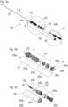
- Fig. 3a-3c
- einen Möbeldämpfer in einer Explosionsdarstellung sowie zwei vergrößerte Detaildarstellungen hierzu,
- Fig. 4a, 4b
- der Möbeldämpfer in einem perspektivischen Querschnitt sowie eine vergrößerte Detaildarstellung hierzu,
- Fig. 5a-5c
- den Möbeldämpfer in einem perspektivischen Schnitt sowie eine erste Detaildarstellung in einem Normalbetrieb und eine zweite Detaildarstellung in einem Überlastfall,
- Fig. 6a-6e
- den Kolben mit der Kolbenstange in einer perspektivischen Ansicht und eine vergrößerte Detaildarstellung hierzu sowie drei verschiedene Ausführungsbeispiele des Verschlusselementes in schematischen Ansichten.
- Fig. 1
- a perspective view of a piece of furniture with a furniture body and drawers that are movable relative to it,
- Fig. 2
- a drawer pull-out guide with a drawer rail, which is to be connected to a drawer side wall,
- Figs. 3a-3c
- an exploded view of a furniture damper and two enlarged detailed views,
- Fig. 4a, 4b
- the furniture damper in a perspective cross section as well as an enlarged detailed view,
- Figs. 5a-5c
- the furniture damper in a perspective section as well as a first detailed representation in normal operation and a second detailed representation in an overload case,
- Figs. 6a-6e
- the piston with the piston rod in a perspective view and an enlarged detailed view of this as well as three different exemplary embodiments of the closure element in schematic views.
Die Schubladenseitenwand 7 ist als Hohlkammerprofil mit einer inneren Profilwand 7a und einer äußeren Profilwand 7b ausgebildet, wobei die Schubladenseitenwand 7 einen nach unten hin offenen und sich in Längsrichtung der Schubladenseitenwand 7 erstreckenden Kanal 17 zur Aufnahme der Ladenschiene 10 aufweist. Die Schubladenseitenwand 7 weist ferner eine erste Befestigungsvorrichtung 38a zum Verbinden mit der Rückwand 8, eine zweite Befestigungsvorrichtung 38b zum Verbinden mit der Frontblende 5 sowie eine Auflage 18 zur Abstützung des Schubladenbodens 6 auf.The drawer side wall 7 is designed as a hollow chamber profile with an
Die Fluidkammer 19a weist eine Hochdruckseite (HP) und eine Niederdruckseite (LP) auf, welche durch den Kolben 20 voneinander getrennt sind. Bei der Ausführung des Dämpfungshubes in Richtung 29 wird der Kolben 20 in die Hockdruckseite (HP) der Fluidkammer 19a eingedrückt. Falls die Druckbeaufschlagung des Kolbens 20 einen vorgegebenen Schwellwert überschreitet, so wird die Überlastsicherung 25 wirksam. Hierfür weist der Kolben 20 zumindest eine Überlastöffnung 30 auf, welche im Normalbetrieb (d.h. unterhalb der vorgegebenen Druckbeaufschlagung auf den Kolben 20) durch das Verschlusselement 20b verschlossen ist. Bei Überschreitung der vorgegebenen Druckbeaufschlagung auf den Kolben 20 wird das Verschlusselement 20b entgegen der Kraft des Kraftspeichers 20a bewegt, sodass die Überlastöffnung 30 des Kolbens 20 freigegeben wird. Durch die Freigabe der Überlastöffnung 30 wird eine fluidleitende Verbindung 31 zwischen der Hochdruckseite (HP) und der Niederdruckseite (LP) freigegeben, sodass der wirksame Strömungsquerschnitt für das Dämpfungsfluid erhöht wird und das Dämpfungsfluid ausgehend von der Hochdruckseite (HP) durch die Überlastöffnung 30 und durch einen Abführkanal 36 der der fluidleitenden Verbindung 31 zur Niederdruckseite (LP) strömt. Auf diese Weise wird ein rascher Druckabbau in der Fluidkammer 19a herbeigeführt.The
Das Verschlusselement 20b weist zumindest eine, vorzugsweise koaxial zur Überlastöffnung 30 angeordnete Drosselöffnung 32 zum Durchtritt des Dämpfungsfluides auf. Diese Drosselöffnung 32 dient zur Stabilisierung des Kolbens 20, insbesondere kurz vor Erreichen der eingedrückten Endstellung. Die Dämpfungswirkung des Kolbens 20 kann, wie in der
Wenn auch der Möbeldämpfer 16 anhand der
Claims (15)
- A furniture fitting comprising at least one furniture damper (16) for dampening a movement of a movably-supported furniture part (3), the furniture damper (16) comprising:- a housing (19),- at least one fluid chamber (19a) arranged in the housing (19), the fluid chamber (19a) having a high-pressure side (HP) and a low-pressure side (LP),- a damping fluid arranged in the fluid chamber (19a),- at least one piston (20) having at least one overload opening (30), the piston (20) being displaceably arranged in the fluid chamber (19a) for performing a damping hub, and the high-pressure side (HP) and the low-pressure side (LP) of the fluid chamber (19a) are separated from each other by the piston (20),- an overload safety device (25) arranged in the piston (20), the overload safety device (25) having a closure element (20b) pressurized by a force storage member (20a), wherein the closure element (20b) blocks the at least one overload opening (30) of the piston (20) below a predetermined threshold value of a pressure application to the piston (20), and unblocks the at least one overload opening (30) of the piston (20) against a force of the force storage member (20a) above the predetermined threshold value of a pressure application to the piston (20), wherein due to unblocking of the overload opening (30), a fluid-conductive connection (31) between the high pressure side (HP) and the low-pressure side (LP) of the fluid chamber (19a) is unblocked,- wherein the closure element (20b) includes at least one throttle opening (32) for the passage of the damping fluid from the high-pressure side (HP) to the low-pressure side (LP) at least when performing the damping hub, characterized in that the throttle opening (32) is open in each operating position of the furniture damper (16).
- The furniture fitting according to claim 1, characterized in that the closure element (20b) has a cylindrical and/or a conical shell surface (33a, 33b), and the damping fluid, above the predetermined threshold value of the pressure application to the piston (20), can be passed along the cylindrical and/or conical shell surface (33a, 33b) downstream of the overload opening (30) through the fluid-conductive connection (31) along the cylindrical and/or conical shell surface (33a, 33b) in an axial direction, or can be deflected away from the cylindrical and/or conical shell surface (33a, 33b) of the closure element (20b) in a radial direction.
- The furniture fitting according to claim 1 or 2, characterized in that the closure element (20b) is movably supported relative to the piston (20) in a longitudinal direction (L) of the piston (20) in a limited manner.
- The furniture fitting according to one of the claims 1 to 3, characterized in that the closure element (20b) includes a cavity (39) in which the force storage member (20a) is at least partially accommodated.
- The furniture fitting according to one of the claims 1 to 4, characterized in that the throttle opening (32) is arranged coaxially with the overload opening (30).
- The furniture fitting according to one of the claims 1 to 5, characterized in that the fluid-conductive connection (31) includes at least one bore or a discharge channel (36) arranged in the piston (20), the discharge channel (36) having a longitudinal direction extending parallel or transverse, preferably at a right angle, to a longitudinal direction (L) of the piston (20).
- The furniture fitting according to one of the claims 1 to 6, characterized in that the piston (20) includes a first piston portion (20d) and at least one second piston portion (20c) connected to the first piston portion (20d).
- The furniture fitting according to claim 7, characterized in that the first piston portion (20d) includes a first recess (37a) in which the closure element (20b) is at least partially accommodated.
- The furniture fitting according to claim 7 or 8, characterized in that the second piston portion (20c) includes a second recess (37b) in which the force storage member (20a) is at least partially accommodated.
- The furniture fitting according to claim 9, characterized in that a longitudinal direction of the first recess (37a) of the first piston portion (20d) and a longitudinal direction of the second recess (37b) of the second piston portion (20c) extend coaxially with each other.
- The furniture fitting according to one of the claims 7 to 10, characterized in that the second piston portion (20c) is connected to a piston rod (21).
- The furniture fitting according to claim 11, characterized in that the piston rod (21) is led out from the housing (19) of the furniture damper (16).
- The furniture fitting according to claim 11 or 12, characterized in that the piston rod (21), for performing the damping hub, is displaceable between a first end position and a second end position, wherein at least one stabilizing element (24) is arranged in the fluid chamber (19a) in a region between the first end position and the second end position, the at least one stabilizing element (24) having an opening (24a) for displaceably receiving the piston rod (21), so that the piston rod (21), upon performing the damping hub, can be stabilized in a direction extending transversely to the longitudinal direction (L) of the piston rod (21).
- The furniture fitting according to one of the claims 1 to 13, characterized in that the force storage member (20a) includes at least one helical spring, preferably a compression spring.
- The furniture fitting according to one of the claims 1 to 14, characterized in that the furniture fitting is configured as a drawer pull-out guide (4), as a holding plate for supporting the furniture damper (16), as furniture hinge, or as a furniture drive for moving a movably-supported furniture part (3) .
Priority Applications (1)
| Application Number | Priority Date | Filing Date | Title |
|---|---|---|---|
| EP24154616.7A EP4357638A2 (en) | 2017-07-13 | 2018-06-22 | Furniture damper |
Applications Claiming Priority (2)
| Application Number | Priority Date | Filing Date | Title |
|---|---|---|---|
| ATA50585/2017A AT520128A1 (en) | 2017-07-13 | 2017-07-13 | furniture damper |
| PCT/AT2018/060127 WO2019010506A1 (en) | 2017-07-13 | 2018-06-22 | Furniture damper |
Related Child Applications (1)
| Application Number | Title | Priority Date | Filing Date |
|---|---|---|---|
| EP24154616.7A Division EP4357638A2 (en) | 2017-07-13 | 2018-06-22 | Furniture damper |
Publications (2)
| Publication Number | Publication Date |
|---|---|
| EP3652402A1 EP3652402A1 (en) | 2020-05-20 |
| EP3652402B1 true EP3652402B1 (en) | 2024-02-07 |
Family
ID=62816275
Family Applications (2)
| Application Number | Title | Priority Date | Filing Date |
|---|---|---|---|
| EP24154616.7A Pending EP4357638A2 (en) | 2017-07-13 | 2018-06-22 | Furniture damper |
| EP18737142.2A Active EP3652402B1 (en) | 2017-07-13 | 2018-06-22 | Furniture damper |
Family Applications Before (1)
| Application Number | Title | Priority Date | Filing Date |
|---|---|---|---|
| EP24154616.7A Pending EP4357638A2 (en) | 2017-07-13 | 2018-06-22 | Furniture damper |
Country Status (8)
| Country | Link |
|---|---|
| US (1) | US11140984B2 (en) |
| EP (2) | EP4357638A2 (en) |
| JP (1) | JP6949193B2 (en) |
| CN (1) | CN110869574B (en) |
| AT (1) | AT520128A1 (en) |
| MY (1) | MY197136A (en) |
| TW (1) | TWI704278B (en) |
| WO (1) | WO2019010506A1 (en) |
Families Citing this family (1)
| Publication number | Priority date | Publication date | Assignee | Title |
|---|---|---|---|---|
| CN112530212B (en) * | 2020-12-29 | 2022-12-20 | 广州海芯教育科技有限公司 | Intelligent manufacturing auxiliary type design teaching equipment |
Citations (3)
| Publication number | Priority date | Publication date | Assignee | Title |
|---|---|---|---|---|
| FR1506717A (en) * | 1965-12-22 | 1967-12-22 | Hoesch Ag | Shock absorber piston with force limiting valve |
| US20040021406A1 (en) * | 2000-09-19 | 2004-02-05 | Luciano Salice | Grease-dampened drawer closing apparatus |
| WO2019039370A1 (en) * | 2017-08-22 | 2019-02-28 | 株式会社パイオラックス | Air damper |
Family Cites Families (20)
| Publication number | Priority date | Publication date | Assignee | Title |
|---|---|---|---|---|
| AT12633B (en) | 1901-09-21 | 1903-07-25 | Andreas Radovanovic | |
| FR1115781A (en) * | 1954-12-06 | 1956-04-30 | Applic Mach Motrices | Back pressure valve |
| JPS4838428U (en) * | 1971-09-10 | 1973-05-12 | ||
| JPS4838428A (en) | 1971-09-20 | 1973-06-06 | ||
| JPS5632137U (en) * | 1979-08-18 | 1981-03-28 | ||
| JPS5632137A (en) | 1979-08-24 | 1981-04-01 | Ricoh Co Ltd | Two-component type diazo copying material |
| FR2594473B1 (en) * | 1986-02-14 | 1994-01-14 | Peugeot Automobiles | STOPPING DEVICE FOR MOBILE PANEL |
| AU671518B2 (en) | 1993-03-18 | 1996-08-29 | Stabilus Gmbh | A locking device for securing objects which are movable relatively to one another |
| DE20107426U1 (en) * | 2001-04-30 | 2001-08-30 | Zimmer Guenther Stephan | Brake controller with air or liquid damping, in particular for damping the end position of drawers, doors or the like. Facilities |
| BR0303572A (en) * | 2002-03-21 | 2004-04-20 | Blum Gmbh Julius | Pneumatic braking and damping device, especially for movable moving parts |
| JP4436154B2 (en) * | 2004-02-23 | 2010-03-24 | 不二ラテックス株式会社 | Drawing guide and shock absorber |
| WO2006029421A1 (en) * | 2004-09-17 | 2006-03-23 | Julius Blum Gmbh | Fluid damper |
| US20070046159A1 (en) * | 2005-08-25 | 2007-03-01 | Knape & Vogt Manufacturing Co. | Motion control bracket with integrated motion control device |
| DE202006003197U1 (en) * | 2006-03-01 | 2007-07-12 | Hettich-Oni Gmbh & Co. Kg | Damper for furniture |
| DE202008002407U1 (en) * | 2007-03-01 | 2008-05-29 | Julius Blum Gmbh | Furniture fitting for the movable storage of a furniture part |
| AT12633U1 (en) * | 2010-08-27 | 2012-09-15 | Blum Gmbh Julius | DAMPING DEVICE WITH OVERLOAD PROTECTION |
| AT12440U1 (en) * | 2010-10-06 | 2012-05-15 | Blum Gmbh Julius | FURNITURE SHOCKS |
| GB2541396A (en) * | 2015-08-17 | 2017-02-22 | Titus D O O Dekani | Improvements in dampers |
| DE102016223486A1 (en) * | 2016-01-27 | 2017-07-27 | Suspa Gmbh | Fluid-filled piston-cylinder unit |
| CN206320220U (en) * | 2016-12-19 | 2017-07-11 | 珠海市皓臻科技有限公司 | With can deformation ring damping buffer |
-
2017
- 2017-07-13 AT ATA50585/2017A patent/AT520128A1/en unknown
-
2018
- 2018-06-22 JP JP2020501307A patent/JP6949193B2/en active Active
- 2018-06-22 EP EP24154616.7A patent/EP4357638A2/en active Pending
- 2018-06-22 CN CN201880046110.8A patent/CN110869574B/en active Active
- 2018-06-22 MY MYPI2020000068A patent/MY197136A/en unknown
- 2018-06-22 WO PCT/AT2018/060127 patent/WO2019010506A1/en unknown
- 2018-06-22 EP EP18737142.2A patent/EP3652402B1/en active Active
- 2018-07-09 TW TW107123697A patent/TWI704278B/en active
-
2019
- 2019-12-31 US US16/731,301 patent/US11140984B2/en active Active
Patent Citations (3)
| Publication number | Priority date | Publication date | Assignee | Title |
|---|---|---|---|---|
| FR1506717A (en) * | 1965-12-22 | 1967-12-22 | Hoesch Ag | Shock absorber piston with force limiting valve |
| US20040021406A1 (en) * | 2000-09-19 | 2004-02-05 | Luciano Salice | Grease-dampened drawer closing apparatus |
| WO2019039370A1 (en) * | 2017-08-22 | 2019-02-28 | 株式会社パイオラックス | Air damper |
Also Published As
| Publication number | Publication date |
|---|---|
| CN110869574A (en) | 2020-03-06 |
| CN110869574B (en) | 2022-02-15 |
| WO2019010506A1 (en) | 2019-01-17 |
| US11140984B2 (en) | 2021-10-12 |
| JP6949193B2 (en) | 2021-10-13 |
| EP4357638A2 (en) | 2024-04-24 |
| US20200128960A1 (en) | 2020-04-30 |
| EP3652402A1 (en) | 2020-05-20 |
| MY197136A (en) | 2023-05-26 |
| TW201920825A (en) | 2019-06-01 |
| TWI704278B (en) | 2020-09-11 |
| AT520128A1 (en) | 2019-01-15 |
| JP2020526689A (en) | 2020-08-31 |
Similar Documents
| Publication | Publication Date | Title |
|---|---|---|
| EP2425080B1 (en) | Damper for furniture | |
| EP2535237B1 (en) | Device for dampening forces of compression | |
| WO2006029421A1 (en) | Fluid damper | |
| EP3439505B1 (en) | Furniture drive | |
| DE102015211891A1 (en) | Frequency-dependent damping valve arrangement | |
| EP3908755B1 (en) | Seat valve | |
| EP3539841B1 (en) | Device for dampening push forces | |
| DE202009006233U1 (en) | Damper cylinder for a damping device for furniture | |
| EP3652402B1 (en) | Furniture damper | |
| DE212011100150U1 (en) | furniture damper | |
| WO2017152195A1 (en) | Furniture damper | |
| AT15703U1 (en) | furniture damper | |
| DE19931362C2 (en) | Damping element for furniture doors | |
| EP2789782B1 (en) | Device for damping the movement of a movable part of a piece of furniture | |
| AT17731U1 (en) | furniture damper | |
| EP3062661B1 (en) | Mechanism for opening a movable furniture component | |
| DE20319598U1 (en) | Automatic return mechanism for drawer includes two spaced couplings with spring, connecting piston rod and latch | |
| EP4178395B1 (en) | Furniture damper | |
| EP3683395A1 (en) | Device for damping the movement of a piece of furniture and guiding device | |
| EP2980441A2 (en) | Device for dampening compressive forces | |
| EP3532690B1 (en) | Braking device for a sliding element | |
| DE10302870B3 (en) | Setting device with gas spring providing damped setting movement for pivoted flap or adjustable seat in automobile or domestic appliance door | |
| DE202015004323U1 (en) | Device for damping compressive forces | |
| DE102006009092A1 (en) | Cavitation-like process e.g. downstream of hydraulic resistance, preventing device for e.g. hydraulic steering assistance system, has piston connected with slider, where throttle point increases throttle effect with increased flow rate | |
| DE102016201386B4 (en) | Gas spring |
Legal Events
| Date | Code | Title | Description |
|---|---|---|---|
| STAA | Information on the status of an ep patent application or granted ep patent |
Free format text: STATUS: UNKNOWN |
|
| STAA | Information on the status of an ep patent application or granted ep patent |
Free format text: STATUS: THE INTERNATIONAL PUBLICATION HAS BEEN MADE |
|
| PUAI | Public reference made under article 153(3) epc to a published international application that has entered the european phase |
Free format text: ORIGINAL CODE: 0009012 |
|
| STAA | Information on the status of an ep patent application or granted ep patent |
Free format text: STATUS: REQUEST FOR EXAMINATION WAS MADE |
|
| 17P | Request for examination filed |
Effective date: 20191217 |
|
| AK | Designated contracting states |
Kind code of ref document: A1 Designated state(s): AL AT BE BG CH CY CZ DE DK EE ES FI FR GB GR HR HU IE IS IT LI LT LU LV MC MK MT NL NO PL PT RO RS SE SI SK SM TR |
|
| AX | Request for extension of the european patent |
Extension state: BA ME |
|
| DAV | Request for validation of the european patent (deleted) | ||
| DAX | Request for extension of the european patent (deleted) | ||
| STAA | Information on the status of an ep patent application or granted ep patent |
Free format text: STATUS: EXAMINATION IS IN PROGRESS |
|
| 17Q | First examination report despatched |
Effective date: 20220407 |
|
| P01 | Opt-out of the competence of the unified patent court (upc) registered |
Effective date: 20230523 |
|
| GRAP | Despatch of communication of intention to grant a patent |
Free format text: ORIGINAL CODE: EPIDOSNIGR1 |
|
| STAA | Information on the status of an ep patent application or granted ep patent |
Free format text: STATUS: GRANT OF PATENT IS INTENDED |
|
| INTG | Intention to grant announced |
Effective date: 20231123 |
|
| GRAS | Grant fee paid |
Free format text: ORIGINAL CODE: EPIDOSNIGR3 |
|
| GRAA | (expected) grant |
Free format text: ORIGINAL CODE: 0009210 |
|
| STAA | Information on the status of an ep patent application or granted ep patent |
Free format text: STATUS: THE PATENT HAS BEEN GRANTED |
|
| AK | Designated contracting states |
Kind code of ref document: B1 Designated state(s): AL AT BE BG CH CY CZ DE DK EE ES FI FR GB GR HR HU IE IS IT LI LT LU LV MC MK MT NL NO PL PT RO RS SE SI SK SM TR |
|
| REG | Reference to a national code |
Ref country code: GB Ref legal event code: FG4D Free format text: NOT ENGLISH |
|
| REG | Reference to a national code |
Ref country code: CH Ref legal event code: EP |
|
| REG | Reference to a national code |
Ref country code: IE Ref legal event code: FG4D Free format text: LANGUAGE OF EP DOCUMENT: GERMAN |
|
| REG | Reference to a national code |
Ref country code: DE Ref legal event code: R096 Ref document number: 502018014082 Country of ref document: DE |