EP3651329A1 - Switched tank converter - Google Patents
Switched tank converter Download PDFInfo
- Publication number
- EP3651329A1 EP3651329A1 EP19194109.5A EP19194109A EP3651329A1 EP 3651329 A1 EP3651329 A1 EP 3651329A1 EP 19194109 A EP19194109 A EP 19194109A EP 3651329 A1 EP3651329 A1 EP 3651329A1
- Authority
- EP
- European Patent Office
- Prior art keywords
- conversion unit
- stage conversion
- switch
- stage
- electrically connected
- Prior art date
- Legal status (The legal status is an assumption and is not a legal conclusion. Google has not performed a legal analysis and makes no representation as to the accuracy of the status listed.)
- Granted
Links
Images







Classifications
-
- H—ELECTRICITY
- H02—GENERATION; CONVERSION OR DISTRIBUTION OF ELECTRIC POWER
- H02M—APPARATUS FOR CONVERSION BETWEEN AC AND AC, BETWEEN AC AND DC, OR BETWEEN DC AND DC, AND FOR USE WITH MAINS OR SIMILAR POWER SUPPLY SYSTEMS; CONVERSION OF DC OR AC INPUT POWER INTO SURGE OUTPUT POWER; CONTROL OR REGULATION THEREOF
- H02M3/00—Conversion of DC power input into DC power output
- H02M3/22—Conversion of DC power input into DC power output with intermediate conversion into AC
- H02M3/24—Conversion of DC power input into DC power output with intermediate conversion into AC by static converters
- H02M3/28—Conversion of DC power input into DC power output with intermediate conversion into AC by static converters using discharge tubes with control electrode or semiconductor devices with control electrode to produce the intermediate AC
- H02M3/325—Conversion of DC power input into DC power output with intermediate conversion into AC by static converters using discharge tubes with control electrode or semiconductor devices with control electrode to produce the intermediate AC using devices of a triode or a transistor type requiring continuous application of a control signal
- H02M3/335—Conversion of DC power input into DC power output with intermediate conversion into AC by static converters using discharge tubes with control electrode or semiconductor devices with control electrode to produce the intermediate AC using devices of a triode or a transistor type requiring continuous application of a control signal using semiconductor devices only
- H02M3/33507—Conversion of DC power input into DC power output with intermediate conversion into AC by static converters using discharge tubes with control electrode or semiconductor devices with control electrode to produce the intermediate AC using devices of a triode or a transistor type requiring continuous application of a control signal using semiconductor devices only with automatic control of the output voltage or current, e.g. flyback converters
- H02M3/33523—Conversion of DC power input into DC power output with intermediate conversion into AC by static converters using discharge tubes with control electrode or semiconductor devices with control electrode to produce the intermediate AC using devices of a triode or a transistor type requiring continuous application of a control signal using semiconductor devices only with automatic control of the output voltage or current, e.g. flyback converters with galvanic isolation between input and output of both the power stage and the feedback loop
-
- H—ELECTRICITY
- H02—GENERATION; CONVERSION OR DISTRIBUTION OF ELECTRIC POWER
- H02M—APPARATUS FOR CONVERSION BETWEEN AC AND AC, BETWEEN AC AND DC, OR BETWEEN DC AND DC, AND FOR USE WITH MAINS OR SIMILAR POWER SUPPLY SYSTEMS; CONVERSION OF DC OR AC INPUT POWER INTO SURGE OUTPUT POWER; CONTROL OR REGULATION THEREOF
- H02M3/00—Conversion of DC power input into DC power output
- H02M3/02—Conversion of DC power input into DC power output without intermediate conversion into AC
- H02M3/04—Conversion of DC power input into DC power output without intermediate conversion into AC by static converters
- H02M3/06—Conversion of DC power input into DC power output without intermediate conversion into AC by static converters using resistors or capacitors, e.g. potential divider
- H02M3/07—Conversion of DC power input into DC power output without intermediate conversion into AC by static converters using resistors or capacitors, e.g. potential divider using capacitors charged and discharged alternately by semiconductor devices with control electrode, e.g. charge pumps
-
- H—ELECTRICITY
- H02—GENERATION; CONVERSION OR DISTRIBUTION OF ELECTRIC POWER
- H02M—APPARATUS FOR CONVERSION BETWEEN AC AND AC, BETWEEN AC AND DC, OR BETWEEN DC AND DC, AND FOR USE WITH MAINS OR SIMILAR POWER SUPPLY SYSTEMS; CONVERSION OF DC OR AC INPUT POWER INTO SURGE OUTPUT POWER; CONTROL OR REGULATION THEREOF
- H02M3/00—Conversion of DC power input into DC power output
- H02M3/02—Conversion of DC power input into DC power output without intermediate conversion into AC
- H02M3/04—Conversion of DC power input into DC power output without intermediate conversion into AC by static converters
- H02M3/06—Conversion of DC power input into DC power output without intermediate conversion into AC by static converters using resistors or capacitors, e.g. potential divider
- H02M3/07—Conversion of DC power input into DC power output without intermediate conversion into AC by static converters using resistors or capacitors, e.g. potential divider using capacitors charged and discharged alternately by semiconductor devices with control electrode, e.g. charge pumps
- H02M3/073—Charge pumps of the Schenkel-type
-
- H—ELECTRICITY
- H02—GENERATION; CONVERSION OR DISTRIBUTION OF ELECTRIC POWER
- H02M—APPARATUS FOR CONVERSION BETWEEN AC AND AC, BETWEEN AC AND DC, OR BETWEEN DC AND DC, AND FOR USE WITH MAINS OR SIMILAR POWER SUPPLY SYSTEMS; CONVERSION OF DC OR AC INPUT POWER INTO SURGE OUTPUT POWER; CONTROL OR REGULATION THEREOF
- H02M3/00—Conversion of DC power input into DC power output
- H02M3/22—Conversion of DC power input into DC power output with intermediate conversion into AC
- H02M3/24—Conversion of DC power input into DC power output with intermediate conversion into AC by static converters
- H02M3/28—Conversion of DC power input into DC power output with intermediate conversion into AC by static converters using discharge tubes with control electrode or semiconductor devices with control electrode to produce the intermediate AC
-
- H—ELECTRICITY
- H02—GENERATION; CONVERSION OR DISTRIBUTION OF ELECTRIC POWER
- H02M—APPARATUS FOR CONVERSION BETWEEN AC AND AC, BETWEEN AC AND DC, OR BETWEEN DC AND DC, AND FOR USE WITH MAINS OR SIMILAR POWER SUPPLY SYSTEMS; CONVERSION OF DC OR AC INPUT POWER INTO SURGE OUTPUT POWER; CONTROL OR REGULATION THEREOF
- H02M3/00—Conversion of DC power input into DC power output
- H02M3/22—Conversion of DC power input into DC power output with intermediate conversion into AC
- H02M3/24—Conversion of DC power input into DC power output with intermediate conversion into AC by static converters
- H02M3/28—Conversion of DC power input into DC power output with intermediate conversion into AC by static converters using discharge tubes with control electrode or semiconductor devices with control electrode to produce the intermediate AC
- H02M3/325—Conversion of DC power input into DC power output with intermediate conversion into AC by static converters using discharge tubes with control electrode or semiconductor devices with control electrode to produce the intermediate AC using devices of a triode or a transistor type requiring continuous application of a control signal
- H02M3/335—Conversion of DC power input into DC power output with intermediate conversion into AC by static converters using discharge tubes with control electrode or semiconductor devices with control electrode to produce the intermediate AC using devices of a triode or a transistor type requiring continuous application of a control signal using semiconductor devices only
-
- H—ELECTRICITY
- H02—GENERATION; CONVERSION OR DISTRIBUTION OF ELECTRIC POWER
- H02M—APPARATUS FOR CONVERSION BETWEEN AC AND AC, BETWEEN AC AND DC, OR BETWEEN DC AND DC, AND FOR USE WITH MAINS OR SIMILAR POWER SUPPLY SYSTEMS; CONVERSION OF DC OR AC INPUT POWER INTO SURGE OUTPUT POWER; CONTROL OR REGULATION THEREOF
- H02M3/00—Conversion of DC power input into DC power output
- H02M3/22—Conversion of DC power input into DC power output with intermediate conversion into AC
- H02M3/24—Conversion of DC power input into DC power output with intermediate conversion into AC by static converters
- H02M3/28—Conversion of DC power input into DC power output with intermediate conversion into AC by static converters using discharge tubes with control electrode or semiconductor devices with control electrode to produce the intermediate AC
- H02M3/325—Conversion of DC power input into DC power output with intermediate conversion into AC by static converters using discharge tubes with control electrode or semiconductor devices with control electrode to produce the intermediate AC using devices of a triode or a transistor type requiring continuous application of a control signal
- H02M3/335—Conversion of DC power input into DC power output with intermediate conversion into AC by static converters using discharge tubes with control electrode or semiconductor devices with control electrode to produce the intermediate AC using devices of a triode or a transistor type requiring continuous application of a control signal using semiconductor devices only
- H02M3/33569—Conversion of DC power input into DC power output with intermediate conversion into AC by static converters using discharge tubes with control electrode or semiconductor devices with control electrode to produce the intermediate AC using devices of a triode or a transistor type requiring continuous application of a control signal using semiconductor devices only having several active switching elements
- H02M3/33576—Conversion of DC power input into DC power output with intermediate conversion into AC by static converters using discharge tubes with control electrode or semiconductor devices with control electrode to produce the intermediate AC using devices of a triode or a transistor type requiring continuous application of a control signal using semiconductor devices only having several active switching elements having at least one active switching element at the secondary side of an isolation transformer
-
- H—ELECTRICITY
- H02—GENERATION; CONVERSION OR DISTRIBUTION OF ELECTRIC POWER
- H02M—APPARATUS FOR CONVERSION BETWEEN AC AND AC, BETWEEN AC AND DC, OR BETWEEN DC AND DC, AND FOR USE WITH MAINS OR SIMILAR POWER SUPPLY SYSTEMS; CONVERSION OF DC OR AC INPUT POWER INTO SURGE OUTPUT POWER; CONTROL OR REGULATION THEREOF
- H02M1/00—Details of apparatus for conversion
- H02M1/0067—Converter structures employing plural converter units, other than for parallel operation of the units on a single load
- H02M1/007—Plural converter units in cascade
-
- H—ELECTRICITY
- H02—GENERATION; CONVERSION OR DISTRIBUTION OF ELECTRIC POWER
- H02M—APPARATUS FOR CONVERSION BETWEEN AC AND AC, BETWEEN AC AND DC, OR BETWEEN DC AND DC, AND FOR USE WITH MAINS OR SIMILAR POWER SUPPLY SYSTEMS; CONVERSION OF DC OR AC INPUT POWER INTO SURGE OUTPUT POWER; CONTROL OR REGULATION THEREOF
- H02M1/00—Details of apparatus for conversion
- H02M1/0095—Hybrid converter topologies, e.g. NPC mixed with flying capacitor, thyristor converter mixed with MMC or charge pump mixed with buck
-
- H—ELECTRICITY
- H02—GENERATION; CONVERSION OR DISTRIBUTION OF ELECTRIC POWER
- H02M—APPARATUS FOR CONVERSION BETWEEN AC AND AC, BETWEEN AC AND DC, OR BETWEEN DC AND DC, AND FOR USE WITH MAINS OR SIMILAR POWER SUPPLY SYSTEMS; CONVERSION OF DC OR AC INPUT POWER INTO SURGE OUTPUT POWER; CONTROL OR REGULATION THEREOF
- H02M3/00—Conversion of DC power input into DC power output
- H02M3/02—Conversion of DC power input into DC power output without intermediate conversion into AC
- H02M3/04—Conversion of DC power input into DC power output without intermediate conversion into AC by static converters
- H02M3/06—Conversion of DC power input into DC power output without intermediate conversion into AC by static converters using resistors or capacitors, e.g. potential divider
- H02M3/07—Conversion of DC power input into DC power output without intermediate conversion into AC by static converters using resistors or capacitors, e.g. potential divider using capacitors charged and discharged alternately by semiconductor devices with control electrode, e.g. charge pumps
- H02M3/073—Charge pumps of the Schenkel-type
- H02M3/075—Charge pumps of the Schenkel-type including a plurality of stages and two sets of clock signals, one set for the odd and one set for the even numbered stages
-
- Y—GENERAL TAGGING OF NEW TECHNOLOGICAL DEVELOPMENTS; GENERAL TAGGING OF CROSS-SECTIONAL TECHNOLOGIES SPANNING OVER SEVERAL SECTIONS OF THE IPC; TECHNICAL SUBJECTS COVERED BY FORMER USPC CROSS-REFERENCE ART COLLECTIONS [XRACs] AND DIGESTS
- Y02—TECHNOLOGIES OR APPLICATIONS FOR MITIGATION OR ADAPTATION AGAINST CLIMATE CHANGE
- Y02B—CLIMATE CHANGE MITIGATION TECHNOLOGIES RELATED TO BUILDINGS, e.g. HOUSING, HOUSE APPLIANCES OR RELATED END-USER APPLICATIONS
- Y02B70/00—Technologies for an efficient end-user side electric power management and consumption
- Y02B70/10—Technologies improving the efficiency by using switched-mode power supplies [SMPS], i.e. efficient power electronics conversion e.g. power factor correction or reduction of losses in power supplies or efficient standby modes
Definitions
- the present disclosure relates to a converter, and more particularly to a switched tank converter.
- the two-stage converter system includes a front-stage converter and a rear-stage converter.
- the front-stage converter needs higher efficiency.
- the front-stage converter is a LLC converter, a phase-shifted full-bridge converter or a switched tank converter.
- the rear-stage converter is usually a buck converter. Since the two-stage converter system has high frequency, small volume, high dynamic response and associated benefits, the two-stage converter system is widely applied to the data center.
- the switched tank converter In comparison with the LLC converter and the phase-shifted full-bridge converter, the switched tank converter is not equipped with a transformer. Consequently, the volume of the switched tank converter is smaller than the volume of the LLC converter and the volume of the phase-shifted full-bridge converter. Moreover, at the low transformer ratio, the operating efficiency of the switched tank converter is higher than the operating efficiency of the LLC converter and the operating efficiency of the phase-shifted full-bridge converter. Recently, the switched tank converter is widely used as the front-stage converter of the two-stage converter system.
- the conventional switched tank converter includes a plurality of conversion units.
- the switched tank converter has a multi-stage conversion structure.
- the conventional switched tank converters are divided into two types, i.e., a first-type switched tank converter and a second-type switched tank converter.
- the transformer ratio is added by 1. That is, if the first-type switched tank converter has an N-stage conversion structure, the highest transformer ratio is (N+1).
- the transformer ratio is added by 2. That is, if the second-type switched tank converter has an N-stage conversion structure, the highest transformer ratio is 2N.
- the applications of the first-type switched tank converter and the second-type switched tank converter are limited.
- the first-type switched tank converter needs a 15-stage conversion structure to achieve the transformer ratio of 16:1
- the second-type switched tank converter needs an 8-stage conversion structure to achieve the transformer ratio of 16:1. That is, the circuitry of the first-type switched tank converter or the second-type switched tank converter is complicated and not cost-effective.
- a switched tank converter includes N conversion units, which are arranged in N stages, wherein N is larger than or equal to 3. Each conversion unit is selected from one of a first-type conversion unit and a second-type conversion unit. Each conversion unit includes an input end, an output end, a support capacitor, a half-bridge inverter circuit, a half-bridge rectifier circuit and a resonant circuit. A first end of the support capacitor is electrically connected with the output end. A first end of the half-bridge inverter circuit is electrically connected with the input end. A second end of the half-bridge inverter circuit is electrically connected with the output end.
- a first end of the half-bridge rectifier circuit is electrically connected with a ground end.
- a second end of the half-bridge rectifier circuit is electrically connected with the first end of the support capacitor of the first-stage conversion unit.
- a first end of the resonant circuit is electrically connected with a middle point of the half-bridge inverter circuit.
- a second end of the resonant circuit is electrically connected with a middle point of the half-bridge rectifier circuit.
- a second end of the support capacitor of each first-type conversion unit is electrically connected with the ground end.
- Each second-type conversion unit includes a half-bridge clamping circuit. A first end of the half-bridge clamping circuit is electrically connected with the ground end.
- a middle point of the half-bridge clamping circuit is electrically connected with the second end of the support capacitor of the second-type conversion unit.
- the output end of each conversion unit is electrically connected with the input end of a next-stage conversion unit.
- the output end of the first-stage conversion unit is electrically connected with a load end.
- the first-stage conversion unit is the first-type conversion unit.
- the input end of the Nth-stage conversion unit is electrically connected with a power end.
- at least one conversion unit of the third-stage conversion unit to the Nth-stage conversion unit is the second-type conversion unit.
- the second end of the half-bridge clamping circuit of each second-type conversion unit of the second-stage conversion unit to the Nth-stage conversion unit is electrically connected with the first end of the support capacitor of the lower-stage conversion unit.
- the second end of the half-bridge clamping circuit of at least one second-type conversion unit of the third-stage conversion unit to the Nth-stage conversion unit is not electrically connected with the first end of the support capacitor of the first-stage conversion unit.
- An object of the present disclosure provides a switched tank converter.
- the switched tank converter has an N-stage conversion structure to achieve the highest transformer ratio of 2 N .
- the circuitry of the switched tank converter is simplified and cost-effective.
- Another object of the present disclosure provides a switched tank converter with a plurality of conversion units.
- the conversion units are classified into first-type conversion units and second-type conversion units.
- first-type conversion units and second-type conversion unit or the connecting relationships are changed, different transformer ratios can be achieved.
- one or more different DC voltages are outputted according to the number of the first-type conversion units.
- the transformer ratio of the switched tank converter can be dynamically adjusted.
- the present disclosure provides a switched tank converter.
- the switched tank converter is a DC/DC switched tank converter.
- the switched tank converter includes N conversion units, which are arranged in N stages, wherein N is an integer larger than or equal to 3.
- Each conversion unit is a first-type conversion unit or a second-type conversion unit.
- each conversion unit includes an input end, an output end, a support capacitor, a half-bridge inverter circuit, a half-bridge rectifier circuit and a resonant circuit.
- the support capacitor has a first end and a second end. The first end of the support capacitor is electrically connected with the output end of the corresponding conversion unit.
- the half-bridge inverter circuit has a first end and a second end.
- the first end of the half-bridge inverter circuit is electrically connected with the input end of the corresponding conversion unit.
- the second end of the half-bridge inverter circuit is electrically connected with the output end of the corresponding conversion unit.
- the half-bridge rectifier circuit has a first end and a second end. The first end of the half-bridge rectifier circuit is electrically connected with a ground end.
- the second end of the half-bridge rectifier circuit of each conversion unit is electrically connected with the first end of the support capacitor of the first-stage conversion unit.
- the resonant circuit has a first end and a second end. The first end of the resonant circuit is electrically connected with a middle point of the half-bridge inverter circuit.
- the second end of the resonant circuit is electrically connected with a middle point of the half-bridge rectifier circuit.
- the second end of the support capacitor of each first-type conversion unit is electrically connected with the ground end.
- Each second-type conversion unit includes a half-bridge clamping circuit. A first end of the half-bridge clamping circuit is electrically connected with the ground end. A middle point of the half-bridge clamping circuit is electrically connected with the second end of the support capacitor of the corresponding second-type conversion unit.
- the output end of each conversion unit is electrically connected with the input end of a next-stage conversion unit.
- the output end of the first-stage conversion unit is electrically connected with a load end.
- the first-stage conversion unit is the first-type conversion unit.
- the input end of the Nth-stage conversion unit is electrically connected with a power end.
- at least one conversion unit of the third-stage conversion unit to the Nth-stage conversion unit is the second-type conversion unit.
- the second end of the half-bridge clamping circuit of each second-type conversion unit of the second-stage conversion unit to the Nth-stage conversion unit is electrically connected with the first end of the support capacitor of the lower-stage conversion unit.
- the second end of the half-bridge clamping circuit of at least one second-type conversion unit of the third-stage conversion unit to the Nth-stage conversion unit is not electrically connected with the first end of the support capacitor of the first-stage conversion unit.
- FIG. 1A is a schematic circuit diagram illustrating a switched tank converter according to a first embodiment of the present disclosure.
- the switched tank converter 1 is electrically connected between a load end 8 and a power end 9.
- the switched tank converter 1 includes N conversion units 2, which are arranged in N stages. That is, the switched tank converter 1 has an N-stage conversion structure, wherein N is an integer larger than or equal to 3.
- Each conversion unit 2 is operated at a variable frequency or a fixed frequency.
- the switched tank converter 1 has a 4-stage conversion structure with four conversion units 2.
- the first-stage conversion unit 2 is electrically connected with the load end 8.
- the last-stage conversion unit 2 is electrically connected with the power end 9.
- the four conversion units 2 include a first-stage conversion unit 2, a second-stage conversion unit 2, a third-stage conversion unit 2 and a fourth-stage conversion unit 2 from right to left of FIG. 1A .
- Each of the four conversion units 2 includes an input end 20, an output end 21, a support capacitor C, a half-bridge inverter circuit 22, a half-bridge rectifier circuit 23 and a resonant circuit 24.
- the support capacitor C has a first end and a second end. The first end of the support capacitor C is electrically connected with the output end 21 of the corresponding conversion unit 2.
- the half-bridge inverter circuit 22 has a first end and a second end. The first end of the half-bridge inverter circuit 22 is electrically connected with the input end 20 of the corresponding conversion unit 2.
- the second end of the half-bridge inverter circuit 22 is electrically connected with the output end 21 of the corresponding conversion unit 2.
- the half-bridge rectifier circuit 23 has a first end and a second end. The first end of the half-bridge rectifier circuit 23 of each conversion unit 2 is electrically connected with a ground end. The second end of the half-bridge rectifier circuit 23 of each conversion unit 2 is electrically connected with the first end of the support capacitor C of the first-stage conversion unit 2.
- the resonant circuit 24 has a first end and a second end. The first end of the resonant circuit 24 is electrically connected with a middle point of the half-bridge inverter circuit 22. The second end of the resonant circuit 24 is electrically connected with a middle point of the half-bridge rectifier circuit 23.
- the first-stage conversion unit 2 is a first-type conversion unit. Consequently, the second end of the support capacitor C of the first-stage conversion unit 2 is electrically connected with the ground end G.
- the second-stage conversion unit 2, the third-stage conversion unit 2 and the fourth-stage conversion unit 2 are second-type conversion units.
- each of the second-stage conversion unit 2, the third-stage conversion unit 2 and the fourth-stage conversion unit 2 further includes a half-bridge clamping circuit 25.
- a first end of the half-bridge clamping circuit 25 is electrically connected with the ground end G.
- a middle point of the half-bridge clamping circuit 25 is electrically connected with the second end of the support capacitor C of the corresponding conversion unit 2.
- each conversion unit 2 is electrically connected with the input end 20 of the next-stage conversion unit 2. That is, the output end 21 of the fourth-stage conversion unit 2 is electrically connected with the input end 20 of the third-stage conversion unit 2, the output end 21 of the third-stage conversion unit 2 is electrically connected with the input end 20 of the second-stage conversion unit 2, and the output end 21 of the second-stage conversion unit 2 is electrically connected with the input end 20 of the first-stage conversion unit 2.
- the output end 21 of the first-stage conversion unit 2 is electrically connected with the load end 8. Consequently, the DC voltage of the support capacitor C of the first-stage conversion unit 2 is equal to the DC voltage of the load end 8.
- the second end of the half-bridge clamping circuit 25 of the third-stage conversion unit 2 is electrically connected with the first end of the support capacitor C of the second-stage conversion unit 2.
- the second end of the half-bridge clamping circuit 25 of the fourth-stage conversion unit 2 is electrically connected with the first end of the support capacitor C of the third-stage conversion unit 2.
- the second end of the half-bridge clamping circuit 25 of the second-stage conversion unit 2 is electrically connected with the first end of the support capacitor C of the first-stage conversion unit 2.
- each half-bridge clamping circuit 25 includes a first switch S1 and a second switch S2, which have a complementary switch configuration.
- the first switch S1 is electrically connected between the first end of the half-bridge clamping circuit 25 and the second switch S2.
- the second switch S2 is electrically connected between the second end of the half-bridge clamping circuit 25 and the first switch S1.
- Each half-bridge inverter circuit 22 includes a third switch S3 and a fourth switch S4, which have a complementary switch configuration.
- the third switch S3 is electrically connected between the fourth switch S4 and the second end of the half-bridge inverter circuit 22.
- the fourth switch S4 is electrically connected between the third switch S3 and the first end of the half-bridge inverter circuit 22.
- Each half-bridge rectifier circuit 23 includes a fifth switch S5 and a sixth switch S6, which have a complementary switch configuration.
- the fifth switch S5 is electrically connected between the sixth switch S6 and the first end of the half-bridge rectifier circuit 23.
- the sixth switch S6 is electrically connected between the fifth switch S5 and the second end of the half-bridge rectifier circuit 23.
- the third switches S3 of all conversion units 2, the fifth switches S5 of all conversion units 2 and the second switches S2 of the second-type conversion units 2 are synchronously turned on and synchronously turned off.
- the fourth switches S4 of all conversion units 2, the sixth switches S6 of all conversion units 2 and the first switches S1 of the second-type conversion units 2 are synchronously turned on and synchronously turned off. In case that the dead time is ignored, the duty cycle of each of the switches S1, S2, S3, S4, S5 and S6 is 50%.
- the resonant circuit 24 includes a resonant inductor Lr and a resonant capacitor Cr.
- the resonant inductor Lr and the resonant capacitor Cr are connected with each other in series.
- the resonant circuit 24 is an equivalent circuit of a resonant inductor Lr and a resonant capacitor Cr in serial connection.
- the resonant circuit 24 includes one of a resonant inductor Lr and a resonant capacitor Cr.
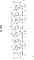
- FIG. 1B is a schematic circuit diagram illustrating the switched tank converter of FIG. 1A , in which all first switches S1, all fourth switches S4 and all sixth switches S6 are turned on and all second switches S2, all third switches S3 and all fifth switches S5 are turned off.
- FIG. 1C is a schematic circuit diagram illustrating the switched tank converter of FIG. 1A , in which all first switches S1, all fourth switches S4 and all sixth switches S6 are turned off and all second switches S2, all third switches S3 and all fifth switches S5 are turned on.
- the resonant capacitor Cr of the first-stage conversion unit 2 discharges electric energy to the support capacitor C of the first-stage conversion unit 2.
- the DC voltage of the resonant capacitor Cr of the first-stage conversion unit 2 is equal to the DC voltage of the support capacitor C of the first-stage conversion unit 2.
- the DC voltage of the support capacitor C of the first-stage conversion unit 2 is Vo.
- the support capacitor C of the second-stage conversion unit 2 discharges electric energy to the resonant capacitor Cr and the support capacitor C of the first-stage conversion unit 2.
- the DC voltage of the resonant capacitor Cr of the first-stage conversion unit 2 is equal to the DC voltage of the support capacitor C of the first-stage conversion unit 2 (i.e., Vo).
- the DC voltage of the support capacitor C of the second-stage conversion unit 2 is equal to the sum of the DC voltages of the resonant capacitor Cr and the support capacitor C of the first-stage conversion unit 2. That is, the DC voltage of the support capacitor C of the second-stage conversion unit 2 is equal to 2Vo.
- the resonant capacitor Cr of the second-stage conversion unit 2 discharges electric energy to the support capacitor C of the second-stage conversion unit 2 and the support capacitor C of the first-stage conversion unit 2.
- the DC voltage of the support capacitor C of the first-stage conversion unit 2 is equal to Vo
- the DC voltage of the support capacitor C of the second-stage conversion unit 2 is equal to 2Vo.
- the DC voltage of the resonant capacitor Cr of the second-stage conversion unit 2 is equal to the sum of the DC voltage of the support capacitor C of the second-stage conversion unit 2 and the DC voltage of the support capacitor C of the first-stage conversion unit 2. That is, the DC voltage of the resonant capacitor Cr of the second-stage conversion unit 2 is equal to 3Vo.
- the support capacitor C of the third-stage conversion unit 2 discharges electric energy to the resonant capacitor Cr of the second-stage conversion unit 2 and the support capacitor C of the first-stage conversion unit 2.
- the DC voltage of the resonant capacitor Cr of the second-stage conversion unit 2 is equal to 3Vo
- the DC voltage of the support capacitor C of the first-stage conversion unit 2 is equal to Vo.
- the DC voltage of the support capacitor C of the third-stage conversion unit 2 is equal to the sum of the DC voltage of the resonant capacitor Cr of the second-stage conversion unit 2 and the DC voltage of the support capacitor C of the first-stage conversion unit 2. That is, the DC voltage of the support capacitor C of the third-stage conversion unit 2 is equal to 4Vo.
- the resonant capacitor Cr of the third-stage conversion unit 2 discharges electric energy to the support capacitor C of the third-stage conversion unit 2, the support capacitor C of the second-stage conversion unit 2 and the support capacitor C of the first-stage conversion unit 2.
- the DC voltage of the support capacitor C of the first-stage conversion unit 2 is equal to Vo
- the DC voltage of the support capacitor C of the second-stage conversion unit 2 is equal to 2Vo
- the DC voltage of the support capacitor C of the third-stage conversion unit 2 is equal to 4Vo.
- the DC voltage of the resonant capacitor Cr of the third-stage conversion unit 2 is equal to the sum of the DC voltage of the support capacitor C of the third-stage conversion unit 2, the DC voltage of the support capacitor C of the second-stage conversion unit 2 and the DC voltage of the support capacitor C of the first-stage conversion unit 2. That is, the DC voltage of the resonant capacitor Cr of the third-stage conversion unit 2 is equal to 7Vo.
- the support capacitor C of the fourth-stage conversion unit 2 discharges electric energy to the resonant capacitor Cr of the third-stage conversion unit 2 and the support capacitor C of the first-stage conversion unit 2.
- the DC voltage of the resonant capacitor Cr of the third-stage conversion unit 2 is equal to 7Vo
- the DC voltage of the support capacitor C of the first-stage conversion unit 2 is equal to Vo.
- the DC voltage of the support capacitor C of the fourth-stage conversion unit 2 is equal to the sum of the DC voltage of the resonant capacitor Cr of the third-stage conversion unit 2 and the DC voltage of the support capacitor C of the first-stage conversion unit 2. That is, the DC voltage of the support capacitor C of the fourth-stage conversion unit 2 is equal to 8Vo.
- the resonant capacitor Cr of the fourth-stage conversion unit 2 discharges electric energy to the support capacitor C of the fourth-stage conversion unit 2, the support capacitor C of the third-stage conversion unit 2, the support capacitor C of the second-stage conversion unit 2 and the support capacitor C of the first-stage conversion unit 2.
- the DC voltage of the support capacitor C of the first-stage conversion unit 2 is equal to Vo
- the DC voltage of the support capacitor C of the second-stage conversion unit 2 is equal to 2Vo
- the DC voltage of the support capacitor C of the third-stage conversion unit 2 is equal to 4Vo
- the DC voltage of the support capacitor C of the fourth-stage conversion unit 2 is equal to 8Vo.
- the DC voltage of the resonant capacitor Cr of the fourth-stage conversion unit 2 is equal to the sum of the DC voltage of the support capacitor C of the fourth-stage conversion unit 2, the DC voltage of the support capacitor C of the third-stage conversion unit 2, the DC voltage of the support capacitor C of the second-stage conversion unit 2 and the DC voltage of the support capacitor C of the first-stage conversion unit 2. That is, the DC voltage of the resonant capacitor Cr of the fourth-stage conversion unit 2 is equal to 15Vo.
- the support capacitor C of the power end 9 discharges electric energy to the resonant capacitor Cr of the fourth-stage conversion unit 2 and the support capacitor C of the first-stage conversion unit 2.
- the DC voltage of the resonant capacitor Cr of the fourth-stage conversion unit 2 is equal to 15Vo
- the DC voltage of the support capacitor C of the first-stage conversion unit 2 is equal to Vo.
- the DC voltage of the power end 9 is equal to the sum of the DC voltage of the resonant capacitor Cr of the fourth-stage conversion unit 2 and the DC voltage of the support capacitor C of the first-stage conversion unit 2. That is, the DC voltage of the power end 9 is equal to 16Vo.
- the conventional first-type switched tank converter needs a 15-stage conversion structure to achieve the transformer ratio of 16:1, and the conventional second-type switched tank converter needs an 8-stage conversion structure to achieve the transformer ratio of 16:1.
- the switched tank converter 1 needs a 4-stage conversion structure to achieve the transformer ratio of 16:1. In other words, the circuitry of the switched tank converter 1 is simplified and cost-effective.
- the switched tank converter 1 has an N-stage conversion structure.
- the first-stage conversion unit 2 is the first-type conversion unit 2.
- Each of the second-stage conversion unit 2 to the Nth-stage conversion unit 2 is the second-type conversion unit 2.
- the switched tank converter 1 has the highest transformer ratio (i.e., 2 N ).
- the conventional switched tank converter can achieve the highest transformer ratio of (N+1) or 2N. In case that the high transformer ratio is required, the circuitry of the switched tank converter 1 is simplified and cost-effective.
- FIG. 2A is a schematic circuit diagram illustrating a switched tank converter according to a second embodiment of the present disclosure.
- the switched tank converter 3 has a 4-stage conversion structure with four conversion units 2.
- the first-stage conversion unit 2 is a first-type conversion unit
- the second-stage conversion unit 2 the third-stage conversion unit 2 and the fourth-stage conversion unit 2 are second-type conversion units.
- the connection relationship between the half-bridge clamping circuit 25 and the support capacitor C is distinguished.
- the second end of the half-bridge clamping circuit 25 of the each conversion unit 2 is electrically connected with the first end of the support capacitor C of the next-stage conversion unit.
- the second end of the half-bridge clamping circuit 25 of the third-stage conversion unit 2 is electrically connected with the first end of the support capacitor C of the second-stage conversion unit 2
- the second end of the half-bridge clamping circuit 25 of the fourth-stage conversion unit 2 is electrically connected with the first end of the support capacitor C of the third-stage conversion unit 2.
- the second end of the half-bridge clamping circuit 25 of the fourth-stage conversion unit 2 is electrically connected with the first end of the support capacitor C of the second-stage conversion unit 2.
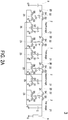
- FIG. 2B is a schematic circuit diagram illustrating the switched tank converter of FIG. 2A , in which all first switches, all fourth switches and all sixth switches are turned on and all second switches, all third switches and all fifth switches are turned off.
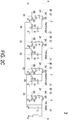
- FIG. 2C is a schematic circuit diagram illustrating the switched tank converter of FIG. 2A , in which all first switches, all fourth switches and all sixth switches are turned off and all second switches, all third switches and all fifth switches are turned on.
- the resonant capacitor Cr of the first-stage conversion unit 2 discharges electric energy to the support capacitor C of the first-stage conversion unit 2.
- the DC voltage of the resonant capacitor Cr of the first-stage conversion unit 2 is equal to the DC voltage of the support capacitor C of the first-stage conversion unit 2.
- the DC voltage of the support capacitor C of the first-stage conversion unit 2 is Vo.
- the support capacitor C of the second-stage conversion unit 2 discharges electric energy to the resonant capacitor Cr and the support capacitor C of the first-stage conversion unit 2.
- the DC voltage of the resonant capacitor Cr of the first-stage conversion unit 2 is equal to the DC voltage of the support capacitor C of the first-stage conversion unit 2 (i.e., Vo).
- the DC voltage of the support capacitor C of the second-stage conversion unit 2 is equal to the sum of the DC voltages of the resonant capacitor Cr and the support capacitor C of the first-stage conversion unit 2. That is, the DC voltage of the support capacitor C of the second-stage conversion unit 2 is equal to 2Vo.
- the rest may be deduced by analogy. That is, the DC voltage of the power end 9 is equal to 12Vo.
- the 4-stage conversion structure of the switched tank converter 3 achieves the transformer ratio of 12:1.
- the switched tank converter 1 achieves the transformer ratio of 16:1.
- the switched tank converter 3 achieves the transformer ratio of 12:1.
- the transformer ratio is adjustable according to the result of judging whether the second end of the half-bridge clamping circuit 25 of any second-type conversion unit 2 of the third-stage conversion unit 2 to the Nth-stage conversion unit 2 is electrically connected with the first end of the support capacitor C of the next-stage conversion unit 2. Consequently, even if the stage number of the switched tank converter is identical, the transformer ratio is diversified.
- the second-stage conversion unit 2 is the first-type conversion unit or the second-type conversion unit.
- the second end of the half-bridge clamping circuit 25 of the second-stage conversion unit 2 is electrically connected with the first end of the support capacitor C of the first-stage conversion unit 2.
- at least one of the conversion units 2 of the third-stage conversion unit 2 to the Nth-stage conversion unit 2 is the second-type conversion unit, and the other conversion units are the first-type conversion units.
- the second end of the half-bridge clamping circuit 25 of each second-type conversion unit 2 is electrically connected with the first end of the support capacitor C of the lower-stage conversion unit.
- the second end of the half-bridge clamping circuit 25 of at least one second-type conversion unit 2 is not electrically connected with the first end of the support capacitor C of the first-stage conversion unit 2.
- FIG. 3A is a schematic circuit diagram illustrating a switched tank converter according to a third embodiment of the present disclosure.
- the switched tank converter 4 has a 3-stage conversion structure with three conversion units 2.
- the first-stage conversion unit 2 and the second-stage conversion unit 2 are first-type conversion units, and the third-stage conversion unit 2 is a second-type conversion unit 2.
- the second end of the half-bridge clamping circuit 25 of the third-stage conversion unit 2 is electrically connected with the first end of the support capacitor C of the second-stage conversion unit 2.
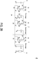
- FIG. 3B is a schematic circuit diagram illustrating the switched tank converter of FIG. 3A , in which all first switches, all fourth switches and all sixth switches are turned on and all second switches, all third switches and all fifth switches are turned off.
- FIG. 3C is a schematic circuit diagram illustrating the switched tank converter of FIG. 3A , in which all first switches, all fourth switches and all sixth switches are turned off and all second switches, all third switches and all fifth switches are turned on.
- the resonant capacitor Cr of the first-stage conversion unit 2 discharges electric energy to the support capacitor C of the first-stage conversion unit 2.
- the DC voltage of the resonant capacitor Cr of the first-stage conversion unit 2 is equal to the DC voltage of the support capacitor C of the first-stage conversion unit 2.
- the DC voltage of the support capacitor C of the first-stage conversion unit 2 is Vo.
- the support capacitor C of the second-stage conversion unit 2 discharges electric energy to the resonant capacitor Cr and the support capacitor C of the first-stage conversion unit 2.
- the DC voltage of the resonant capacitor Cr of the first-stage conversion unit 2 is equal to the DC voltage of the support capacitor C of the first-stage conversion unit 2 (i.e., Vo).
- the DC voltage of the support capacitor C of the second-stage conversion unit 2 is equal to the sum of the DC voltages of the resonant capacitor Cr and the support capacitor C of the first-stage conversion unit 2. That is, the DC voltage of the support capacitor C of the second-stage conversion unit 2 is equal to 2Vo.
- the resonant capacitor Cr of the second-stage conversion unit 2 discharges electric energy to the support capacitor C of the second-stage conversion unit 2.
- the DC voltage of the support capacitor C of the second-stage conversion unit 2 is 2Vo
- the DC voltage of the resonant capacitor Cr of the second-stage conversion unit 2 is equal to the DC voltage of the support capacitor C of the second-stage conversion unit 2. That is, the DC voltage of the resonant capacitor Cr of the second-stage conversion unit 2 is 2Vo.
- the support capacitor C of the third-stage conversion unit 2 discharges electric energy to the resonant capacitor Cr of the second-stage conversion unit 2 and the support capacitor C of the first-stage conversion unit 2.
- the DC voltage of the resonant capacitor Cr of the second-stage conversion unit 2 is equal to 2Vo
- the DC voltage of the support capacitor C of the first-stage conversion unit 2 is equal to Vo.
- the DC voltage of the support capacitor C of the third-stage conversion unit 2 is equal to the sum of the DC voltage of the resonant capacitor Cr of the second-stage conversion unit 2 and the DC voltage of the support capacitor C of the first-stage conversion unit 2. That is, the DC voltage of the support capacitor C of the third-stage conversion unit 2 is equal to 3Vo.
- the resonant capacitor Cr of the third-stage conversion unit 2 discharges electric energy to the support capacitor C of the third-stage conversion unit 2 and the support capacitor C of the second-stage conversion unit 2.
- the DC voltage of the support capacitor C of the second-stage conversion unit 2 is 2Vo
- the DC voltage of the support capacitor C of the third-stage conversion unit 2 is equal to 3Vo.
- the DC voltage of the resonant capacitor Cr of the third-stage conversion unit 2 is equal to the sum of the DC voltage of the support capacitor C of the third-stage conversion unit 2 and the DC voltage of the support capacitor C of the second-stage conversion unit 2. That is, the DC voltage of the resonant capacitor Cr of the third-stage conversion unit 2 is equal to 5Vo.
- the support capacitor C of the power end 9 discharges electric energy to the resonant capacitor Cr of the third-stage conversion unit 2 and the support capacitor C of the first-stage conversion unit 2.
- the DC voltage of the resonant capacitor Cr of the third-stage conversion unit 2 is equal to 5Vo
- the DC voltage of the support capacitor C of the first-stage conversion unit 2 is equal to Vo.
- the DC voltage of the power end 9 is equal to the sum of the DC voltage of the resonant capacitor Cr of the third-stage conversion unit 2 and the DC voltage of the support capacitor C of the first-stage conversion unit 2. That is, the DC voltage of the power end 9 is equal to 6Vo.
- the second-stage conversion unit 2 is the first-type conversion unit. That is, the second end of the support capacitor C of the second-stage conversion unit 2 is electrically connected with the ground end G.
- the output end 21 of the first-stage conversion unit 2 outputs a DC voltage with the transformer ratio of 6:1 to the load end 8, and the output end 21 of the second-stage conversion unit 2 with the transformer ratio of 3:1 to another load end 8 (not shown). Consequently, the switched tank converter 4 can output two different DC voltages.
- the method of controlling the switches may be varied to achieve different transformer ratios.
- the third switches of all conversion units, the fifth switches of all conversion units and the second switches of all second-type conversion units are synchronously turned on and synchronously turned off, and the fourth switches of all conversion units, the sixth switches of all conversion units and the first switches of all second-type conversion units are synchronously turned on and synchronously turned off.
- a first transformer ratio is achieved.
- the first switch of at least one conversion unit of the second-stage conversion unit to the Nth-stage conversion unit is continuously turned on and the second switch is continuously turned off.
- the third switches of all conversion units, the fifth switches of all conversion units and the other second switches are synchronously turned on and synchronously turned off, and the fourth switches of all conversion units, the sixth switches of all conversion units and the other first switches are synchronously turned on and synchronously turned off. Under this circumstance, a second transformer ratio is achieved.
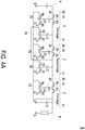
- FIG. 4A is a schematic circuit diagram illustrating a switched tank converter according to a fourth embodiment of the present disclosure.
- the switched tank converter 5 has a 3-stage conversion structure with three conversion units 2.
- the first-stage conversion unit 2 is a first-type conversion unit
- the second-stage conversion unit 2 and the third-stage conversion unit 2 are second-type conversion units 2.
- the second end of the half-bridge clamping circuit 25 of the second-stage conversion unit 2 is electrically connected with the first end of the support capacitor C of the first-stage conversion unit 2.
- the second end of the half-bridge clamping circuit 25 of the third-stage conversion unit 2 is electrically connected with the first end of the support capacitor C of the second-stage conversion unit 2.
- FIG. 4B is a schematic circuit diagram illustrating the switched tank converter of FIG. 4A in a first operation mode, in which all first switches, all fourth switches and all sixth switches are turned on and all second switches, all third switches and all fifth switches are turned off.
- FIG. 4C is a schematic circuit diagram illustrating the switched tank converter of FIG. 4A in a first operation mode, in which all first switches, all fourth switches and all sixth switches are turned off and all second switches, all third switches and all fifth switches are turned on.
- the operations of the switches S1 ⁇ S6 are similar to those of the first, second and third embodiments. That is, the third switches S3 of all conversion units 2, the fifth switches S5 of all conversion units 2 and the second switches S2 of the second-type conversion units 2 are synchronously turned on and synchronously turned off. In addition, the fourth switches S4 of all conversion units 2, the sixth switches S6 of all conversion units 2 and the first switches S1 of the second-type conversion units 2 are synchronously turned on and synchronously turned off. Consequently, the switched tank converter 5 achieves the transformer ratio of 8:1.
- FIG. 4D is a schematic circuit diagram illustrating the switched tank converter of FIG. 4A in a second operation mode, in which the first switch of the second-stage conversion unit is continuously turned on and the second switch of the second-stage conversion unit is continuously turned off, the other first switches, all fourth switches and all sixth switches are turned on and the other second switches, all third switches and all fifth switches are turned off.
- FIG. 4E is a schematic circuit diagram illustrating the switched tank converter of FIG.
- the first switch S1 of the second-stage conversion unit 2 is continuously turned on, and the second switch S2 of the second-stage conversion unit 2 is continuously turned off.
- the third switches S3 of all conversion units 2, the fifth switches S5 of all conversion units 2 and the other second switches S2 are synchronously turned on and synchronously turned off.
- the fourth switches S4 of all conversion units 2, the sixth switches S6 of all conversion units 2 and the other first switches S1 are synchronously turned on and synchronously turned off.
- the resonant capacitor Cr of the first-stage conversion unit 2 discharges electric energy to the support capacitor C of the first-stage conversion unit 2.
- the DC voltage of the resonant capacitor Cr of the first-stage conversion unit 2 is equal to the DC voltage of the support capacitor C of the first-stage conversion unit 2.
- the DC voltage of the support capacitor C of the first-stage conversion unit 2 is Vo.
- the support capacitor C of the second-stage conversion unit 2 discharges electric energy to the resonant capacitor Cr and the support capacitor C of the first-stage conversion unit 2.
- the DC voltage of the resonant capacitor Cr of the first-stage conversion unit 2 is equal to the DC voltage of the support capacitor C of the first-stage conversion unit 2 (i.e., Vo).
- the DC voltage of the support capacitor C of the second-stage conversion unit 2 is equal to the sum of the DC voltages of the resonant capacitor Cr and the support capacitor C of the first-stage conversion unit 2. That is, the DC voltage of the support capacitor C of the second-stage conversion unit 2 is equal to 2Vo.
- the resonant capacitor Cr of the second-stage conversion unit 2 discharges electric energy to the support capacitor C of the second-stage conversion unit 2.
- the DC voltage of the support capacitor C of the second-stage conversion unit 2 is equal to 2Vo
- the DC voltage of the resonant capacitor Cr of the second-stage conversion unit 2 is equal to the DC voltage of the support capacitor C of the second-stage conversion unit 2 (i.e., 2Vo).
- the support capacitor C of the third-stage conversion unit 2 discharges electric energy to the resonant capacitor Cr of the second-stage conversion unit 2 and the support capacitor C of the first-stage conversion unit 2.
- the DC voltage of the resonant capacitor Cr of the second-stage conversion unit 2 is equal to 2Vo
- the DC voltage of the support capacitor C of the first-stage conversion unit 2 is equal to Vo.
- the DC voltage of the support capacitor C of the third-stage conversion unit 2 is equal to the sum of the DC voltage of the resonant capacitor Cr of the second-stage conversion unit 2 and the DC voltage of the support capacitor C of the first-stage conversion unit 2. That is, the DC voltage of the support capacitor C of the third-stage conversion unit 2 is equal to 3Vo.
- the resonant capacitor Cr of the third-stage conversion unit 2 discharges electric energy to the support capacitor C of the third-stage conversion unit 2 and the support capacitor C of the second-stage conversion unit 2.
- the DC voltage of the support capacitor C of the second-stage conversion unit 2 is equal to 2Vo
- the DC voltage of the support capacitor C of the third-stage conversion unit 2 is equal to 3Vo.
- the DC voltage of the resonant capacitor Cr of the third-stage conversion unit 2 is equal to the sum of the DC voltage of the support capacitor C of the third-stage conversion unit 2 and the DC voltage of the support capacitor C of the second-stage conversion unit 2. That is, the DC voltage of the resonant capacitor Cr of the third-stage conversion unit 2 is equal to 5Vo.
- the support capacitor C of the power end 9 discharges electric energy to the resonant capacitor Cr of the third-stage conversion unit 2 and the support capacitor C of the first-stage conversion unit 2.
- the DC voltage of the resonant capacitor Cr of the third-stage conversion unit 2 is equal to 5Vo
- the DC voltage of the support capacitor C of the first-stage conversion unit 2 is equal to Vo.
- the DC voltage of the power end 9 is equal to the sum of the DC voltage of the resonant capacitor Cr of the third-stage conversion unit 2 and the DC voltage of the support capacitor C of the first-stage conversion unit 2. That is, the DC voltage of the power end 9 is equal to 6Vo.
- the switched tank converter in different operation modes can achieve different transformer ratios.
- the present disclosure provides a switched tank DC converter.
- the switched tank converter includes N conversion units 2, which are arranged in N stages, wherein N is an integer larger than or equal to 3.
- Each conversion unit is a first-type conversion unit or a second-type conversion unit.
- the output end of each conversion unit is electrically connected with the input end of a next-stage conversion unit.
- the output end of the first-stage conversion unit is electrically connected with a load end.
- the first-stage conversion unit is the first-type conversion unit.
- the input end of the Nth-stage conversion unit is electrically connected with a power end.
- at least one conversion unit of the third-stage conversion unit to the Nth-stage conversion unit is the second-type conversion unit.
- the second end of the half-bridge clamping circuit of each second-type conversion unit of the second-stage conversion unit to the Nth-stage conversion unit is electrically connected with the first end of the support capacitor of the lower-stage conversion unit.
- the second end of the half-bridge clamping circuit of at least one second-type conversion unit of the third-stage conversion unit to the Nth-stage conversion unit is not electrically connected with the first end of the support capacitor of the first-stage conversion unit.
- the switched tank converter has an N-stage conversion structure to achieve the highest transformer ratio of 2 N .
- the circuitry of the switched tank converter is simplified and cost-effective.
- different transformer ratios can be achieved.
- one or more different DC voltages are outputted according to the number of the first-type conversion units.
- the transformer ratio of the switched tank converter can be dynamically adjusted.
Landscapes
- Engineering & Computer Science (AREA)
- Power Engineering (AREA)
- Dc-Dc Converters (AREA)
Abstract
Description
- The present disclosure relates to a converter, and more particularly to a switched tank converter.
- With the continuous expansion of the data center market of the global Internet, the amount of the electric power supplied to the data center is gradually increased, and the power supply demands on the processor of the data center are gradually increased. Therefore, a converter system with a two-stage configuration is usually required to power the processor of the data center. The two-stage converter system includes a front-stage converter and a rear-stage converter. The front-stage converter needs higher efficiency. For example, the front-stage converter is a LLC converter, a phase-shifted full-bridge converter or a switched tank converter. In addition, the rear-stage converter is usually a buck converter. Since the two-stage converter system has high frequency, small volume, high dynamic response and associated benefits, the two-stage converter system is widely applied to the data center.
- In comparison with the LLC converter and the phase-shifted full-bridge converter, the switched tank converter is not equipped with a transformer. Consequently, the volume of the switched tank converter is smaller than the volume of the LLC converter and the volume of the phase-shifted full-bridge converter. Moreover, at the low transformer ratio, the operating efficiency of the switched tank converter is higher than the operating efficiency of the LLC converter and the operating efficiency of the phase-shifted full-bridge converter. Recently, the switched tank converter is widely used as the front-stage converter of the two-stage converter system.
- The conventional switched tank converter includes a plurality of conversion units. In other words, the switched tank converter has a multi-stage conversion structure. According to the transformer ratio, the conventional switched tank converters are divided into two types, i.e., a first-type switched tank converter and a second-type switched tank converter. As the stage number (or the conversion unit number) of the first-type switched tank converter is increased by one, the transformer ratio is added by 1. That is, if the first-type switched tank converter has an N-stage conversion structure, the highest transformer ratio is (N+1). As the stage number (or the conversion unit number) of the second-type switched tank converter is increased by one, the transformer ratio is added by 2. That is, if the second-type switched tank converter has an N-stage conversion structure, the highest transformer ratio is 2N.
- However, in case that the high transformer ratio is required, the applications of the first-type switched tank converter and the second-type switched tank converter are limited. For example, the first-type switched tank converter needs a 15-stage conversion structure to achieve the transformer ratio of 16:1, and the second-type switched tank converter needs an 8-stage conversion structure to achieve the transformer ratio of 16:1. That is, the circuitry of the first-type switched tank converter or the second-type switched tank converter is complicated and not cost-effective.
- Therefore, there is a need of providing an improved switched tank converter.
- In accordance with an aspect of the present disclosure, a switched tank converter is provided. The switched tank converter includes N conversion units, which are arranged in N stages, wherein N is larger than or equal to 3. Each conversion unit is selected from one of a first-type conversion unit and a second-type conversion unit. Each conversion unit includes an input end, an output end, a support capacitor, a half-bridge inverter circuit, a half-bridge rectifier circuit and a resonant circuit. A first end of the support capacitor is electrically connected with the output end. A first end of the half-bridge inverter circuit is electrically connected with the input end. A second end of the half-bridge inverter circuit is electrically connected with the output end. A first end of the half-bridge rectifier circuit is electrically connected with a ground end. A second end of the half-bridge rectifier circuit is electrically connected with the first end of the support capacitor of the first-stage conversion unit. A first end of the resonant circuit is electrically connected with a middle point of the half-bridge inverter circuit. A second end of the resonant circuit is electrically connected with a middle point of the half-bridge rectifier circuit. A second end of the support capacitor of each first-type conversion unit is electrically connected with the ground end. Each second-type conversion unit includes a half-bridge clamping circuit. A first end of the half-bridge clamping circuit is electrically connected with the ground end. A middle point of the half-bridge clamping circuit is electrically connected with the second end of the support capacitor of the second-type conversion unit. The output end of each conversion unit is electrically connected with the input end of a next-stage conversion unit. The output end of the first-stage conversion unit is electrically connected with a load end. The first-stage conversion unit is the first-type conversion unit. The input end of the Nth-stage conversion unit is electrically connected with a power end. Moreover, at least one conversion unit of the third-stage conversion unit to the Nth-stage conversion unit is the second-type conversion unit. The second end of the half-bridge clamping circuit of each second-type conversion unit of the second-stage conversion unit to the Nth-stage conversion unit is electrically connected with the first end of the support capacitor of the lower-stage conversion unit. The second end of the half-bridge clamping circuit of at least one second-type conversion unit of the third-stage conversion unit to the Nth-stage conversion unit is not electrically connected with the first end of the support capacitor of the first-stage conversion unit.
- The above contents of the present disclosure will become more readily apparent to those ordinarily skilled in the art after reviewing the following detailed description and accompanying drawings, in which:
-
-
FIG. 1A is a schematic circuit diagram illustrating a switched tank converter according to a first embodiment of the present disclosure; -
FIG. 1B is a schematic circuit diagram illustrating the switched tank converter ofFIG. 1A , in which all first switches, all fourth switches and all sixth switches are turned on and all second switches, all third switches and all fifth switches are turned off; -
FIG. 1C is a schematic circuit diagram illustrating the switched tank converter ofFIG. 1A , in which all first switches, all fourth switches and all sixth switches are turned off and all second switches, all third switches and all fifth switches are turned on; -
FIG. 2A is a schematic circuit diagram illustrating a switched tank converter according to a second embodiment of the present disclosure; -
FIG. 2B is a schematic circuit diagram illustrating the switched tank converter ofFIG. 2A , in which all first switches, all fourth switches and all sixth switches are turned on and all second switches, all third switches and all fifth switches are turned off; -
FIG. 2C is a schematic circuit diagram illustrating the switched tank converter ofFIG. 2A , in which all first switches, all fourth switches and all sixth switches are turned off and all second switches, all third switches and all fifth switches are turned on; -
FIG. 3A is a schematic circuit diagram illustrating a switched tank converter according to a third embodiment of the present disclosure; -
FIG. 3B is a schematic circuit diagram illustrating the switched tank converter ofFIG. 3A , in which all first switches, all fourth switches and all sixth switches are turned on and all second switches, all third switches and all fifth switches are turned off; -
FIG. 3C is a schematic circuit diagram illustrating the switched tank converter ofFIG. 3A , in which all first switches, all fourth switches and all sixth switches are turned off and all second switches, all third switches and all fifth switches are turned on; -
FIG. 4A is a schematic circuit diagram illustrating a switched tank converter according to a fourth embodiment of the present disclosure; -
FIG. 4B is a schematic circuit diagram illustrating the switched tank converter ofFIG. 4A in a first operation mode, in which all first switches, all fourth switches and all sixth switches are turned on and all second switches, all third switches and all fifth switches are turned off; -
FIG. 4C is a schematic circuit diagram illustrating the switched tank converter ofFIG. 4A in a first operation mode, in which all first switches, all fourth switches and all sixth switches are turned off and all second switches, all third switches and all fifth switches are turned on; -
FIG. 4D is a schematic circuit diagram illustrating the switched tank converter ofFIG. 4A in a second operation mode, in which the first switch of the second-stage conversion unit is continuously turned on and the second switch of the second-stage conversion unit is continuously turned off, the other first switches, all fourth switches and all sixth switches are turned on and the other second switches, all third switches and all fifth switches are turned off; and -
FIG. 4E is a schematic circuit diagram illustrating the switched tank converter ofFIG. 4A in a second operation mode, in which the first switch of the second-stage conversion unit is continuously turned on and the second switch of the second-stage conversion unit is continuously turned off, the other first switches, all fourth switches and all sixth switches are turned off and the other second switches, all third switches and all fifth switches are turned on. - The present disclosure will now be described more specifically with reference to the following embodiments. It is to be noted that the following descriptions of some embodiments of this disclosure are presented herein for purpose of illustration and description only. It is not intended to be exhaustive or to be limited to the precise form disclosed.
- An object of the present disclosure provides a switched tank converter. The switched tank converter has an N-stage conversion structure to achieve the highest transformer ratio of 2N. In case that the high transformer ratio is required, the circuitry of the switched tank converter is simplified and cost-effective.
- Another object of the present disclosure provides a switched tank converter with a plurality of conversion units. The conversion units are classified into first-type conversion units and second-type conversion units. As the numbers of the first-type conversion unit and the second-type conversion unit or the connecting relationships are changed, different transformer ratios can be achieved. Moreover, one or more different DC voltages are outputted according to the number of the first-type conversion units. As the method of controlling the switches is changed, the transformer ratio of the switched tank converter can be dynamically adjusted.
- The present disclosure provides a switched tank converter. For example, the switched tank converter is a DC/DC switched tank converter. The switched tank converter includes N conversion units, which are arranged in N stages, wherein N is an integer larger than or equal to 3. Each conversion unit is a first-type conversion unit or a second-type conversion unit. Regardless of the type of the conversion unit, each conversion unit includes an input end, an output end, a support capacitor, a half-bridge inverter circuit, a half-bridge rectifier circuit and a resonant circuit. The support capacitor has a first end and a second end. The first end of the support capacitor is electrically connected with the output end of the corresponding conversion unit. The half-bridge inverter circuit has a first end and a second end. The first end of the half-bridge inverter circuit is electrically connected with the input end of the corresponding conversion unit. The second end of the half-bridge inverter circuit is electrically connected with the output end of the corresponding conversion unit. The half-bridge rectifier circuit has a first end and a second end. The first end of the half-bridge rectifier circuit is electrically connected with a ground end. The second end of the half-bridge rectifier circuit of each conversion unit is electrically connected with the first end of the support capacitor of the first-stage conversion unit. The resonant circuit has a first end and a second end. The first end of the resonant circuit is electrically connected with a middle point of the half-bridge inverter circuit. The second end of the resonant circuit is electrically connected with a middle point of the half-bridge rectifier circuit. The second end of the support capacitor of each first-type conversion unit is electrically connected with the ground end. Each second-type conversion unit includes a half-bridge clamping circuit. A first end of the half-bridge clamping circuit is electrically connected with the ground end. A middle point of the half-bridge clamping circuit is electrically connected with the second end of the support capacitor of the corresponding second-type conversion unit. The output end of each conversion unit is electrically connected with the input end of a next-stage conversion unit. The output end of the first-stage conversion unit is electrically connected with a load end. The first-stage conversion unit is the first-type conversion unit. The input end of the Nth-stage conversion unit is electrically connected with a power end. Moreover, at least one conversion unit of the third-stage conversion unit to the Nth-stage conversion unit is the second-type conversion unit. The second end of the half-bridge clamping circuit of each second-type conversion unit of the second-stage conversion unit to the Nth-stage conversion unit is electrically connected with the first end of the support capacitor of the lower-stage conversion unit. The second end of the half-bridge clamping circuit of at least one second-type conversion unit of the third-stage conversion unit to the Nth-stage conversion unit is not electrically connected with the first end of the support capacitor of the first-stage conversion unit.
- The concepts of the switched tank converter will be described as follows. In the following embodiments, similar component parts and elements are designated by identical numeral references.
-
FIG. 1A is a schematic circuit diagram illustrating a switched tank converter according to a first embodiment of the present disclosure. As shown inFIG. 1A , the switchedtank converter 1 is electrically connected between aload end 8 and apower end 9. The switchedtank converter 1 includesN conversion units 2, which are arranged in N stages. That is, the switchedtank converter 1 has an N-stage conversion structure, wherein N is an integer larger than or equal to 3. Eachconversion unit 2 is operated at a variable frequency or a fixed frequency. In this embodiment, the switchedtank converter 1 has a 4-stage conversion structure with fourconversion units 2. The first-stage conversion unit 2 is electrically connected with theload end 8. The last-stage conversion unit 2 is electrically connected with thepower end 9. That is, the fourconversion units 2 include a first-stage conversion unit 2, a second-stage conversion unit 2, a third-stage conversion unit 2 and a fourth-stage conversion unit 2 from right to left ofFIG. 1A . Each of the fourconversion units 2 includes aninput end 20, anoutput end 21, a support capacitor C, a half-bridge inverter circuit 22, a half-bridge rectifier circuit 23 and aresonant circuit 24. The support capacitor C has a first end and a second end. The first end of the support capacitor C is electrically connected with theoutput end 21 of thecorresponding conversion unit 2. The half-bridge inverter circuit 22 has a first end and a second end. The first end of the half-bridge inverter circuit 22 is electrically connected with theinput end 20 of thecorresponding conversion unit 2. The second end of the half-bridge inverter circuit 22 is electrically connected with theoutput end 21 of thecorresponding conversion unit 2. The half-bridge rectifier circuit 23 has a first end and a second end. The first end of the half-bridge rectifier circuit 23 of eachconversion unit 2 is electrically connected with a ground end. The second end of the half-bridge rectifier circuit 23 of eachconversion unit 2 is electrically connected with the first end of the support capacitor C of the first-stage conversion unit 2. Theresonant circuit 24 has a first end and a second end. The first end of theresonant circuit 24 is electrically connected with a middle point of the half-bridge inverter circuit 22. The second end of theresonant circuit 24 is electrically connected with a middle point of the half-bridge rectifier circuit 23. - In this embodiment, the first-
stage conversion unit 2 is a first-type conversion unit. Consequently, the second end of the support capacitor C of the first-stage conversion unit 2 is electrically connected with the ground end G. The second-stage conversion unit 2, the third-stage conversion unit 2 and the fourth-stage conversion unit 2 are second-type conversion units. In this embodiment, each of the second-stage conversion unit 2, the third-stage conversion unit 2 and the fourth-stage conversion unit 2 further includes a half-bridge clamping circuit 25. A first end of the half-bridge clamping circuit 25 is electrically connected with the ground end G. A middle point of the half-bridge clamping circuit 25 is electrically connected with the second end of the support capacitor C of thecorresponding conversion unit 2. - Moreover, the
output end 21 of eachconversion unit 2 is electrically connected with theinput end 20 of the next-stage conversion unit 2. That is, theoutput end 21 of the fourth-stage conversion unit 2 is electrically connected with theinput end 20 of the third-stage conversion unit 2, theoutput end 21 of the third-stage conversion unit 2 is electrically connected with theinput end 20 of the second-stage conversion unit 2, and theoutput end 21 of the second-stage conversion unit 2 is electrically connected with theinput end 20 of the first-stage conversion unit 2. Theoutput end 21 of the first-stage conversion unit 2 is electrically connected with theload end 8. Consequently, the DC voltage of the support capacitor C of the first-stage conversion unit 2 is equal to the DC voltage of theload end 8. The second end of the half-bridge clamping circuit 25 of the third-stage conversion unit 2 is electrically connected with the first end of the support capacitor C of the second-stage conversion unit 2. The second end of the half-bridge clamping circuit 25 of the fourth-stage conversion unit 2 is electrically connected with the first end of the support capacitor C of the third-stage conversion unit 2. The second end of the half-bridge clamping circuit 25 of the second-stage conversion unit 2 is electrically connected with the first end of the support capacitor C of the first-stage conversion unit 2. - In this embodiment, each half-
bridge clamping circuit 25 includes a first switch S1 and a second switch S2, which have a complementary switch configuration. The first switch S1 is electrically connected between the first end of the half-bridge clamping circuit 25 and the second switch S2. The second switch S2 is electrically connected between the second end of the half-bridge clamping circuit 25 and the first switch S1. Each half-bridge inverter circuit 22 includes a third switch S3 and a fourth switch S4, which have a complementary switch configuration. The third switch S3 is electrically connected between the fourth switch S4 and the second end of the half-bridge inverter circuit 22. The fourth switch S4 is electrically connected between the third switch S3 and the first end of the half-bridge inverter circuit 22. Each half-bridge rectifier circuit 23 includes a fifth switch S5 and a sixth switch S6, which have a complementary switch configuration. The fifth switch S5 is electrically connected between the sixth switch S6 and the first end of the half-bridge rectifier circuit 23. The sixth switch S6 is electrically connected between the fifth switch S5 and the second end of the half-bridge rectifier circuit 23. - The third switches S3 of all
conversion units 2, the fifth switches S5 of allconversion units 2 and the second switches S2 of the second-type conversion units 2 (e.g., the second-stage conversion unit 2 to the fourth-stage conversion unit 2) are synchronously turned on and synchronously turned off. The fourth switches S4 of allconversion units 2, the sixth switches S6 of allconversion units 2 and the first switches S1 of the second-type conversion units 2 (e.g., the second-stage conversion unit 2 to the fourth-stage conversion unit 2) are synchronously turned on and synchronously turned off. In case that the dead time is ignored, the duty cycle of each of the switches S1, S2, S3, S4, S5 and S6 is 50%. - In this embodiment, the
resonant circuit 24 includes a resonant inductor Lr and a resonant capacitor Cr. The resonant inductor Lr and the resonant capacitor Cr are connected with each other in series. In another embodiment, theresonant circuit 24 is an equivalent circuit of a resonant inductor Lr and a resonant capacitor Cr in serial connection. Alternatively, theresonant circuit 24 includes one of a resonant inductor Lr and a resonant capacitor Cr. - The operations of the switched
tank converter 1 will be described as follows. - Please refer to
FIGS. 1B and1C .FIG. 1B is a schematic circuit diagram illustrating the switched tank converter ofFIG. 1A , in which all first switches S1, all fourth switches S4 and all sixth switches S6 are turned on and all second switches S2, all third switches S3 and all fifth switches S5 are turned off.FIG. 1C is a schematic circuit diagram illustrating the switched tank converter ofFIG. 1A , in which all first switches S1, all fourth switches S4 and all sixth switches S6 are turned off and all second switches S2, all third switches S3 and all fifth switches S5 are turned on. - As shown in
FIG. 1C , when the third switch S3 and the fifth switch S5 of the first-stage conversion unit 2 are turned on, the resonant capacitor Cr of the first-stage conversion unit 2 discharges electric energy to the support capacitor C of the first-stage conversion unit 2. In the steady state, the DC voltage of the resonant capacitor Cr of the first-stage conversion unit 2 is equal to the DC voltage of the support capacitor C of the first-stage conversion unit 2. For example, the DC voltage of the support capacitor C of the first-stage conversion unit 2 is Vo. - As shown in
FIG. 1B , when the first switch S1 of the second-stage conversion unit 2 and the fourth switch S4 and the sixth switch S6 of the first-stage conversion unit 2 are turned on, the support capacitor C of the second-stage conversion unit 2 discharges electric energy to the resonant capacitor Cr and the support capacitor C of the first-stage conversion unit 2. In the steady state, the DC voltage of the resonant capacitor Cr of the first-stage conversion unit 2 is equal to the DC voltage of the support capacitor C of the first-stage conversion unit 2 (i.e., Vo). According to Kirchhoff's Voltage Law (KVL), the DC voltage of the support capacitor C of the second-stage conversion unit 2 is equal to the sum of the DC voltages of the resonant capacitor Cr and the support capacitor C of the first-stage conversion unit 2. That is, the DC voltage of the support capacitor C of the second-stage conversion unit 2 is equal to 2Vo. - As shown in
FIG. 1C , when the second switch S2, the third switch S3 and the fifth switch S5 of the second-stage conversion unit 2 are turned on, the resonant capacitor Cr of the second-stage conversion unit 2 discharges electric energy to the support capacitor C of the second-stage conversion unit 2 and the support capacitor C of the first-stage conversion unit 2. In the steady state, the DC voltage of the support capacitor C of the first-stage conversion unit 2 is equal to Vo, and the DC voltage of the support capacitor C of the second-stage conversion unit 2 is equal to 2Vo. According to Kirchhoff's Voltage Law, the DC voltage of the resonant capacitor Cr of the second-stage conversion unit 2 is equal to the sum of the DC voltage of the support capacitor C of the second-stage conversion unit 2 and the DC voltage of the support capacitor C of the first-stage conversion unit 2. That is, the DC voltage of the resonant capacitor Cr of the second-stage conversion unit 2 is equal to 3Vo. - As shown in
FIG. 1B , when the first switch S1 of the third-stage conversion unit 2 and the fourth switch S4 and the sixth switch S6 of the second-stage conversion unit 2 are turned on, the support capacitor C of the third-stage conversion unit 2 discharges electric energy to the resonant capacitor Cr of the second-stage conversion unit 2 and the support capacitor C of the first-stage conversion unit 2. In the steady state, the DC voltage of the resonant capacitor Cr of the second-stage conversion unit 2 is equal to 3Vo, and the DC voltage of the support capacitor C of the first-stage conversion unit 2 is equal to Vo. According to Kirchhoff's Voltage Law, the DC voltage of the support capacitor C of the third-stage conversion unit 2 is equal to the sum of the DC voltage of the resonant capacitor Cr of the second-stage conversion unit 2 and the DC voltage of the support capacitor C of the first-stage conversion unit 2. That is, the DC voltage of the support capacitor C of the third-stage conversion unit 2 is equal to 4Vo. - As shown in
FIG. 1C , when the second switch S2, the third switch S3 and the fifth switch S5 of the third-stage conversion unit 2 and the second switch S2 of the second-stage conversion unit 2 are turned on, the resonant capacitor Cr of the third-stage conversion unit 2 discharges electric energy to the support capacitor C of the third-stage conversion unit 2, the support capacitor C of the second-stage conversion unit 2 and the support capacitor C of the first-stage conversion unit 2. In the steady state, the DC voltage of the support capacitor C of the first-stage conversion unit 2 is equal to Vo, the DC voltage of the support capacitor C of the second-stage conversion unit 2 is equal to 2Vo, and the DC voltage of the support capacitor C of the third-stage conversion unit 2 is equal to 4Vo. According to Kirchhoff's Voltage Law, the DC voltage of the resonant capacitor Cr of the third-stage conversion unit 2 is equal to the sum of the DC voltage of the support capacitor C of the third-stage conversion unit 2, the DC voltage of the support capacitor C of the second-stage conversion unit 2 and the DC voltage of the support capacitor C of the first-stage conversion unit 2. That is, the DC voltage of the resonant capacitor Cr of the third-stage conversion unit 2 is equal to 7Vo. - As shown in
FIG. 1B , when the first switch S1 of the fourth-stage conversion unit 2 and the fourth switch S4 and the sixth switch S6 of the third-stage conversion unit 2 are turned on, the support capacitor C of the fourth-stage conversion unit 2 discharges electric energy to the resonant capacitor Cr of the third-stage conversion unit 2 and the support capacitor C of the first-stage conversion unit 2. In the steady state, the DC voltage of the resonant capacitor Cr of the third-stage conversion unit 2 is equal to 7Vo, and the DC voltage of the support capacitor C of the first-stage conversion unit 2 is equal to Vo. According to Kirchhoff's Voltage Law, the DC voltage of the support capacitor C of the fourth-stage conversion unit 2 is equal to the sum of the DC voltage of the resonant capacitor Cr of the third-stage conversion unit 2 and the DC voltage of the support capacitor C of the first-stage conversion unit 2. That is, the DC voltage of the support capacitor C of the fourth-stage conversion unit 2 is equal to 8Vo. - As shown in
FIG. 1C , when the second switch S2, the third switch S3 and the fifth switch S5 of the fourth-stage conversion unit 2, the second switch S2 of the third-stage conversion unit 2 and the second switch S2 of the second-stage conversion unit 2 are turned on, the resonant capacitor Cr of the fourth-stage conversion unit 2 discharges electric energy to the support capacitor C of the fourth-stage conversion unit 2, the support capacitor C of the third-stage conversion unit 2, the support capacitor C of the second-stage conversion unit 2 and the support capacitor C of the first-stage conversion unit 2. In the steady state, the DC voltage of the support capacitor C of the first-stage conversion unit 2 is equal to Vo, the DC voltage of the support capacitor C of the second-stage conversion unit 2 is equal to 2Vo, the DC voltage of the support capacitor C of the third-stage conversion unit 2 is equal to 4Vo, and the DC voltage of the support capacitor C of the fourth-stage conversion unit 2 is equal to 8Vo. According to Kirchhoff's Voltage Law, the DC voltage of the resonant capacitor Cr of the fourth-stage conversion unit 2 is equal to the sum of the DC voltage of the support capacitor C of the fourth-stage conversion unit 2, the DC voltage of the support capacitor C of the third-stage conversion unit 2, the DC voltage of the support capacitor C of the second-stage conversion unit 2 and the DC voltage of the support capacitor C of the first-stage conversion unit 2. That is, the DC voltage of the resonant capacitor Cr of the fourth-stage conversion unit 2 is equal to 15Vo. - As shown in
FIG. 1B , when the fourth switch S4 and the sixth switch S6 of the fourth-stage conversion unit 2 are turned on, the support capacitor C of thepower end 9 discharges electric energy to the resonant capacitor Cr of the fourth-stage conversion unit 2 and the support capacitor C of the first-stage conversion unit 2. In the steady state, the DC voltage of the resonant capacitor Cr of the fourth-stage conversion unit 2 is equal to 15Vo, and the DC voltage of the support capacitor C of the first-stage conversion unit 2 is equal to Vo. According to Kirchhoff's Voltage Law, the DC voltage of thepower end 9 is equal to the sum of the DC voltage of the resonant capacitor Cr of the fourth-stage conversion unit 2 and the DC voltage of the support capacitor C of the first-stage conversion unit 2. That is, the DC voltage of thepower end 9 is equal to 16Vo. - As mentioned above, the conventional first-type switched tank converter needs a 15-stage conversion structure to achieve the transformer ratio of 16:1, and the conventional second-type switched tank converter needs an 8-stage conversion structure to achieve the transformer ratio of 16:1. In the first embodiment of the present disclosure, the switched
tank converter 1 needs a 4-stage conversion structure to achieve the transformer ratio of 16:1. In other words, the circuitry of the switchedtank converter 1 is simplified and cost-effective. - From the above descriptions, the switched
tank converter 1 has an N-stage conversion structure. The first-stage conversion unit 2 is the first-type conversion unit 2. Each of the second-stage conversion unit 2 to the Nth-stage conversion unit 2 is the second-type conversion unit 2. In case that the second end of the half-bridge clamping circuit 25 of eachconversion unit 2 is electrically connected with the first end of the support capacitor C of the next-stage conversion unit C, the switchedtank converter 1 has the highest transformer ratio (i.e., 2N). The conventional switched tank converter can achieve the highest transformer ratio of (N+1) or 2N. In case that the high transformer ratio is required, the circuitry of the switchedtank converter 1 is simplified and cost-effective. -
FIG. 2A is a schematic circuit diagram illustrating a switched tank converter according to a second embodiment of the present disclosure. In this embodiment, the switchedtank converter 3 has a 4-stage conversion structure with fourconversion units 2. Like the first embodiment, the first-stage conversion unit 2 is a first-type conversion unit, and the second-stage conversion unit 2, the third-stage conversion unit 2 and the fourth-stage conversion unit 2 are second-type conversion units. In comparison with the first embodiment, the connection relationship between the half-bridge clamping circuit 25 and the support capacitor C is distinguished. In the second-stage conversion unit to the Nth-stage conversion unit of the switchedtank converter 1 of the first embodiment, the second end of the half-bridge clamping circuit 25 of the eachconversion unit 2 is electrically connected with the first end of the support capacitor C of the next-stage conversion unit. That is, the second end of the half-bridge clamping circuit 25 of the third-stage conversion unit 2 is electrically connected with the first end of the support capacitor C of the second-stage conversion unit 2, and the second end of the half-bridge clamping circuit 25 of the fourth-stage conversion unit 2 is electrically connected with the first end of the support capacitor C of the third-stage conversion unit 2. In the switchedtank converter 3 of this embodiment, the second end of the half-bridge clamping circuit 25 of the fourth-stage conversion unit 2 is electrically connected with the first end of the support capacitor C of the second-stage conversion unit 2. - The operations of the switched
tank converter 3 will be described as follows. - Please refer to
FIGS. 2B and2C .FIG. 2B is a schematic circuit diagram illustrating the switched tank converter ofFIG. 2A , in which all first switches, all fourth switches and all sixth switches are turned on and all second switches, all third switches and all fifth switches are turned off.FIG. 2C is a schematic circuit diagram illustrating the switched tank converter ofFIG. 2A , in which all first switches, all fourth switches and all sixth switches are turned off and all second switches, all third switches and all fifth switches are turned on. - As shown in
FIG. 2C , when the third switch S3 and the fifth switch S5 of the first-stage conversion unit 2 are turned on, the resonant capacitor Cr of the first-stage conversion unit 2 discharges electric energy to the support capacitor C of the first-stage conversion unit 2. In the steady state, the DC voltage of the resonant capacitor Cr of the first-stage conversion unit 2 is equal to the DC voltage of the support capacitor C of the first-stage conversion unit 2. For example, the DC voltage of the support capacitor C of the first-stage conversion unit 2 is Vo. - As shown in
FIG. 2B , when the first switch S1 of the second-stage conversion unit 2 and the fourth switch S4 and the sixth switch S6 of the first-stage conversion unit 2 are turned on, the support capacitor C of the second-stage conversion unit 2 discharges electric energy to the resonant capacitor Cr and the support capacitor C of the first-stage conversion unit 2. In the steady state, the DC voltage of the resonant capacitor Cr of the first-stage conversion unit 2 is equal to the DC voltage of the support capacitor C of the first-stage conversion unit 2 (i.e., Vo). According to Kirchhoff's Voltage Law (KVL), the DC voltage of the support capacitor C of the second-stage conversion unit 2 is equal to the sum of the DC voltages of the resonant capacitor Cr and the support capacitor C of the first-stage conversion unit 2. That is, the DC voltage of the support capacitor C of the second-stage conversion unit 2 is equal to 2Vo. The rest may be deduced by analogy. That is, the DC voltage of thepower end 9 is equal to 12Vo. In the second embodiment of the present disclosure, the 4-stage conversion structure of the switchedtank converter 3 achieves the transformer ratio of 12:1. - In the first embodiment, the switched
tank converter 1 achieves the transformer ratio of 16:1. In the second embodiment, the switchedtank converter 3 achieves the transformer ratio of 12:1. In case that the switched tank converter has N-stage conversion structure (N is at least 3) with the first-type conversion unit and the second-type conversion unit, the transformer ratio is adjustable according to the result of judging whether the second end of the half-bridge clamping circuit 25 of any second-type conversion unit 2 of the third-stage conversion unit 2 to the Nth-stage conversion unit 2 is electrically connected with the first end of the support capacitor C of the next-stage conversion unit 2. Consequently, even if the stage number of the switched tank converter is identical, the transformer ratio is diversified. - In some embodiments, the second-
stage conversion unit 2 is the first-type conversion unit or the second-type conversion unit. In case that the second-stage conversion unit 2 is the second-type conversion unit, the second end of the half-bridge clamping circuit 25 of the second-stage conversion unit 2 is electrically connected with the first end of the support capacitor C of the first-stage conversion unit 2. Moreover, at least one of theconversion units 2 of the third-stage conversion unit 2 to the Nth-stage conversion unit 2 is the second-type conversion unit, and the other conversion units are the first-type conversion units. The second end of the half-bridge clamping circuit 25 of each second-type conversion unit 2 is electrically connected with the first end of the support capacitor C of the lower-stage conversion unit. However, the second end of the half-bridge clamping circuit 25 of at least one second-type conversion unit 2 is not electrically connected with the first end of the support capacitor C of the first-stage conversion unit 2. -
FIG. 3A is a schematic circuit diagram illustrating a switched tank converter according to a third embodiment of the present disclosure. In this embodiment, the switchedtank converter 4 has a 3-stage conversion structure with threeconversion units 2. The first-stage conversion unit 2 and the second-stage conversion unit 2 are first-type conversion units, and the third-stage conversion unit 2 is a second-type conversion unit 2. The second end of the half-bridge clamping circuit 25 of the third-stage conversion unit 2 is electrically connected with the first end of the support capacitor C of the second-stage conversion unit 2. - The operations of the switched
tank converter 4 will be described as follows. - Please refer to
FIGS. 3B and3C .FIG. 3B is a schematic circuit diagram illustrating the switched tank converter ofFIG. 3A , in which all first switches, all fourth switches and all sixth switches are turned on and all second switches, all third switches and all fifth switches are turned off.FIG. 3C is a schematic circuit diagram illustrating the switched tank converter ofFIG. 3A , in which all first switches, all fourth switches and all sixth switches are turned off and all second switches, all third switches and all fifth switches are turned on. - As shown in
FIG. 3C , when the third switch S3 and the fifth switch S5 of the first-stage conversion unit 2 are turned on, the resonant capacitor Cr of the first-stage conversion unit 2 discharges electric energy to the support capacitor C of the first-stage conversion unit 2. In the steady state, the DC voltage of the resonant capacitor Cr of the first-stage conversion unit 2 is equal to the DC voltage of the support capacitor C of the first-stage conversion unit 2. For example, the DC voltage of the support capacitor C of the first-stage conversion unit 2 is Vo. - As shown in
FIG. 3B , when the fourth switch S4 and the sixth switch S6 of the first-stage conversion unit 2 are turned on, the support capacitor C of the second-stage conversion unit 2 discharges electric energy to the resonant capacitor Cr and the support capacitor C of the first-stage conversion unit 2. In the steady state, the DC voltage of the resonant capacitor Cr of the first-stage conversion unit 2 is equal to the DC voltage of the support capacitor C of the first-stage conversion unit 2 (i.e., Vo). According to Kirchhoff's Voltage Law, the DC voltage of the support capacitor C of the second-stage conversion unit 2 is equal to the sum of the DC voltages of the resonant capacitor Cr and the support capacitor C of the first-stage conversion unit 2. That is, the DC voltage of the support capacitor C of the second-stage conversion unit 2 is equal to 2Vo. - As shown in
FIG. 3C , when the third switch S3 and the fifth switch S5 of the second-stage conversion unit 2 are turned on, the resonant capacitor Cr of the second-stage conversion unit 2 discharges electric energy to the support capacitor C of the second-stage conversion unit 2. In the steady state, the DC voltage of the support capacitor C of the second-stage conversion unit 2 is 2Vo, the DC voltage of the resonant capacitor Cr of the second-stage conversion unit 2 is equal to the DC voltage of the support capacitor C of the second-stage conversion unit 2. That is, the DC voltage of the resonant capacitor Cr of the second-stage conversion unit 2 is 2Vo. - As shown in
FIG. 3B , when the first switch S1 of the third-stage conversion unit 2 and the fourth switch S4 and the sixth switch S6 of the second-stage conversion unit 2 are turned on, the support capacitor C of the third-stage conversion unit 2 discharges electric energy to the resonant capacitor Cr of the second-stage conversion unit 2 and the support capacitor C of the first-stage conversion unit 2. In the steady state, the DC voltage of the resonant capacitor Cr of the second-stage conversion unit 2 is equal to 2Vo, and the DC voltage of the support capacitor C of the first-stage conversion unit 2 is equal to Vo. According to Kirchhoff's Voltage Law, the DC voltage of the support capacitor C of the third-stage conversion unit 2 is equal to the sum of the DC voltage of the resonant capacitor Cr of the second-stage conversion unit 2 and the DC voltage of the support capacitor C of the first-stage conversion unit 2. That is, the DC voltage of the support capacitor C of the third-stage conversion unit 2 is equal to 3Vo. - As shown in
FIG. 3C , when the second switch S2, the third switch S3 and the fifth switch S5 of the third-stage conversion unit 2 are turned on, the resonant capacitor Cr of the third-stage conversion unit 2 discharges electric energy to the support capacitor C of the third-stage conversion unit 2 and the support capacitor C of the second-stage conversion unit 2. In the steady state, the DC voltage of the support capacitor C of the second-stage conversion unit 2 is 2Vo, and the DC voltage of the support capacitor C of the third-stage conversion unit 2 is equal to 3Vo. According to Kirchhoff's Voltage Law, the DC voltage of the resonant capacitor Cr of the third-stage conversion unit 2 is equal to the sum of the DC voltage of the support capacitor C of the third-stage conversion unit 2 and the DC voltage of the support capacitor C of the second-stage conversion unit 2. That is, the DC voltage of the resonant capacitor Cr of the third-stage conversion unit 2 is equal to 5Vo. - As shown in
FIG. 3B , when the fourth switch S4 and the sixth switch S6 of the third-stage conversion unit 2 are turned on, the support capacitor C of thepower end 9 discharges electric energy to the resonant capacitor Cr of the third-stage conversion unit 2 and the support capacitor C of the first-stage conversion unit 2. In the steady state, the DC voltage of the resonant capacitor Cr of the third-stage conversion unit 2 is equal to 5Vo, and the DC voltage of the support capacitor C of the first-stage conversion unit 2 is equal to Vo. According to Kirchhoff's Voltage Law, the DC voltage of thepower end 9 is equal to the sum of the DC voltage of the resonant capacitor Cr of the third-stage conversion unit 2 and the DC voltage of the support capacitor C of the first-stage conversion unit 2. That is, the DC voltage of thepower end 9 is equal to 6Vo. - In this embodiment, the second-
stage conversion unit 2 is the first-type conversion unit. That is, the second end of the support capacitor C of the second-stage conversion unit 2 is electrically connected with the ground end G. Theoutput end 21 of the first-stage conversion unit 2 outputs a DC voltage with the transformer ratio of 6:1 to theload end 8, and theoutput end 21 of the second-stage conversion unit 2 with the transformer ratio of 3:1 to another load end 8 (not shown). Consequently, the switchedtank converter 4 can output two different DC voltages. - Even if the architecture of the switched tank converter is not changed, the method of controlling the switches may be varied to achieve different transformer ratios. In the above first controlling method, the third switches of all conversion units, the fifth switches of all conversion units and the second switches of all second-type conversion units are synchronously turned on and synchronously turned off, and the fourth switches of all conversion units, the sixth switches of all conversion units and the first switches of all second-type conversion units are synchronously turned on and synchronously turned off. Under this circumstance, a first transformer ratio is achieved. In a second controlling method, the first switch of at least one conversion unit of the second-stage conversion unit to the Nth-stage conversion unit is continuously turned on and the second switch is continuously turned off. The third switches of all conversion units, the fifth switches of all conversion units and the other second switches are synchronously turned on and synchronously turned off, and the fourth switches of all conversion units, the sixth switches of all conversion units and the other first switches are synchronously turned on and synchronously turned off. Under this circumstance, a second transformer ratio is achieved.
-
FIG. 4A is a schematic circuit diagram illustrating a switched tank converter according to a fourth embodiment of the present disclosure. In this embodiment, the switchedtank converter 5 has a 3-stage conversion structure with threeconversion units 2. The first-stage conversion unit 2 is a first-type conversion unit, and the second-stage conversion unit 2 and the third-stage conversion unit 2 are second-type conversion units 2. The second end of the half-bridge clamping circuit 25 of the second-stage conversion unit 2 is electrically connected with the first end of the support capacitor C of the first-stage conversion unit 2. The second end of the half-bridge clamping circuit 25 of the third-stage conversion unit 2 is electrically connected with the first end of the support capacitor C of the second-stage conversion unit 2. - Hereinafter, the operations of the switched
tank converter 5 in a first operation mode will be illustrated with reference toFIGS. 4B and4C .FIG. 4B is a schematic circuit diagram illustrating the switched tank converter ofFIG. 4A in a first operation mode, in which all first switches, all fourth switches and all sixth switches are turned on and all second switches, all third switches and all fifth switches are turned off.FIG. 4C is a schematic circuit diagram illustrating the switched tank converter ofFIG. 4A in a first operation mode, in which all first switches, all fourth switches and all sixth switches are turned off and all second switches, all third switches and all fifth switches are turned on. - In the first operation mode, the operations of the switches S1∼S6 are similar to those of the first, second and third embodiments. That is, the third switches S3 of all
conversion units 2, the fifth switches S5 of allconversion units 2 and the second switches S2 of the second-type conversion units 2 are synchronously turned on and synchronously turned off. In addition, the fourth switches S4 of allconversion units 2, the sixth switches S6 of allconversion units 2 and the first switches S1 of the second-type conversion units 2 are synchronously turned on and synchronously turned off. Consequently, the switchedtank converter 5 achieves the transformer ratio of 8:1. - Hereinafter, the operations of the switched
tank converter 5 in a second operation mode will be illustrated with reference toFIGS. 4D and4E .FIG. 4D is a schematic circuit diagram illustrating the switched tank converter ofFIG. 4A in a second operation mode, in which the first switch of the second-stage conversion unit is continuously turned on and the second switch of the second-stage conversion unit is continuously turned off, the other first switches, all fourth switches and all sixth switches are turned on and the other second switches, all third switches and all fifth switches are turned off.FIG. 4E is a schematic circuit diagram illustrating the switched tank converter ofFIG. 4A in a second operation mode, in which the first switch of the second-stage conversion unit is continuously turned on and the second switch of the second-stage conversion unit is continuously turned off, the other first switches, all fourth switches and all sixth switches are turned off and the other second switches, all third switches and all fifth switches are turned on. - In the second operation mode, the first switch S1 of the second-
stage conversion unit 2 is continuously turned on, and the second switch S2 of the second-stage conversion unit 2 is continuously turned off. The third switches S3 of allconversion units 2, the fifth switches S5 of allconversion units 2 and the other second switches S2 are synchronously turned on and synchronously turned off. In addition, the fourth switches S4 of allconversion units 2, the sixth switches S6 of allconversion units 2 and the other first switches S1 are synchronously turned on and synchronously turned off. When the switchedtank converter 5 is in the first operation mode, the transformer ratio of 8:1. When the switchedtank converter 5 is in the second operation mode, a different transformer ratio is achieved. - As shown in
FIG. 4E , when the third switch S3 and the fifth switch S5 of the first-stage conversion unit 2 are turned on, the resonant capacitor Cr of the first-stage conversion unit 2 discharges electric energy to the support capacitor C of the first-stage conversion unit 2. In the steady state, the DC voltage of the resonant capacitor Cr of the first-stage conversion unit 2 is equal to the DC voltage of the support capacitor C of the first-stage conversion unit 2. For example, the DC voltage of the support capacitor C of the first-stage conversion unit 2 is Vo. - As shown in
FIG. 4D , when the first switch S1 of the second-stage conversion unit 2 and the fourth switch S4 and the sixth switch S6 of the first-stage conversion unit 2 are turned on, the support capacitor C of the second-stage conversion unit 2 discharges electric energy to the resonant capacitor Cr and the support capacitor C of the first-stage conversion unit 2. In the steady state, the DC voltage of the resonant capacitor Cr of the first-stage conversion unit 2 is equal to the DC voltage of the support capacitor C of the first-stage conversion unit 2 (i.e., Vo). According to Kirchhoff's Voltage Law, the DC voltage of the support capacitor C of the second-stage conversion unit 2 is equal to the sum of the DC voltages of the resonant capacitor Cr and the support capacitor C of the first-stage conversion unit 2. That is, the DC voltage of the support capacitor C of the second-stage conversion unit 2 is equal to 2Vo. - As shown in
FIG. 4E , when the first switch S1, the third switch S3 and the fifth switch S5 of the second-stage conversion unit 2 are turned on, the resonant capacitor Cr of the second-stage conversion unit 2 discharges electric energy to the support capacitor C of the second-stage conversion unit 2. In the steady state, the DC voltage of the support capacitor C of the second-stage conversion unit 2 is equal to 2Vo, and the DC voltage of the resonant capacitor Cr of the second-stage conversion unit 2 is equal to the DC voltage of the support capacitor C of the second-stage conversion unit 2 (i.e., 2Vo). - As shown in
FIG. 4D , when the first switch S1 of the third-stage conversion unit 2 and the fourth switch S4 and the sixth switch S6 of the second-stage conversion unit 2 are turned on, the support capacitor C of the third-stage conversion unit 2 discharges electric energy to the resonant capacitor Cr of the second-stage conversion unit 2 and the support capacitor C of the first-stage conversion unit 2. In the steady state, the DC voltage of the resonant capacitor Cr of the second-stage conversion unit 2 is equal to 2Vo, and the DC voltage of the support capacitor C of the first-stage conversion unit 2 is equal to Vo. According to Kirchhoff's Voltage Law, the DC voltage of the support capacitor C of the third-stage conversion unit 2 is equal to the sum of the DC voltage of the resonant capacitor Cr of the second-stage conversion unit 2 and the DC voltage of the support capacitor C of the first-stage conversion unit 2. That is, the DC voltage of the support capacitor C of the third-stage conversion unit 2 is equal to 3Vo. - As shown in
FIG. 4E , when the second switch S2, the third switch S3 and the fifth switch S5 of the third-stage conversion unit 2 and the first switch S1 of the second-stage conversion unit 2 are turned on, the resonant capacitor Cr of the third-stage conversion unit 2 discharges electric energy to the support capacitor C of the third-stage conversion unit 2 and the support capacitor C of the second-stage conversion unit 2. In the steady state, the DC voltage of the support capacitor C of the second-stage conversion unit 2 is equal to 2Vo, and the DC voltage of the support capacitor C of the third-stage conversion unit 2 is equal to 3Vo. According to Kirchhoff's Voltage Law, the DC voltage of the resonant capacitor Cr of the third-stage conversion unit 2 is equal to the sum of the DC voltage of the support capacitor C of the third-stage conversion unit 2 and the DC voltage of the support capacitor C of the second-stage conversion unit 2. That is, the DC voltage of the resonant capacitor Cr of the third-stage conversion unit 2 is equal to 5Vo. - As shown in
FIG. 4D , when the fourth switch S4 and the sixth switch S6 of the third-stage conversion unit 2 are turned on, the support capacitor C of thepower end 9 discharges electric energy to the resonant capacitor Cr of the third-stage conversion unit 2 and the support capacitor C of the first-stage conversion unit 2. In the steady state, the DC voltage of the resonant capacitor Cr of the third-stage conversion unit 2 is equal to 5Vo, and the DC voltage of the support capacitor C of the first-stage conversion unit 2 is equal to Vo. According to Kirchhoff's Voltage Law, the DC voltage of thepower end 9 is equal to the sum of the DC voltage of the resonant capacitor Cr of the third-stage conversion unit 2 and the DC voltage of the support capacitor C of the first-stage conversion unit 2. That is, the DC voltage of thepower end 9 is equal to 6Vo. - As mentioned above, if the architecture of the switched tank converter is not changed, the switched tank converter in different operation modes can achieve different transformer ratios.
- From the above descriptions, the present disclosure provides a switched tank DC converter. The switched tank converter includes
N conversion units 2, which are arranged in N stages, wherein N is an integer larger than or equal to 3. Each conversion unit is a first-type conversion unit or a second-type conversion unit. The output end of each conversion unit is electrically connected with the input end of a next-stage conversion unit. The output end of the first-stage conversion unit is electrically connected with a load end. The first-stage conversion unit is the first-type conversion unit. The input end of the Nth-stage conversion unit is electrically connected with a power end. Moreover, at least one conversion unit of the third-stage conversion unit to the Nth-stage conversion unit is the second-type conversion unit. The second end of the half-bridge clamping circuit of each second-type conversion unit of the second-stage conversion unit to the Nth-stage conversion unit is electrically connected with the first end of the support capacitor of the lower-stage conversion unit. The second end of the half-bridge clamping circuit of at least one second-type conversion unit of the third-stage conversion unit to the Nth-stage conversion unit is not electrically connected with the first end of the support capacitor of the first-stage conversion unit. - The switched tank converter has an N-stage conversion structure to achieve the highest transformer ratio of 2N. In case that the high transformer ratio is required, the circuitry of the switched tank converter is simplified and cost-effective. As the numbers of the first-type conversion unit and the second-type conversion unit or the connecting relationships are changed, different transformer ratios can be achieved. Moreover, one or more different DC voltages are outputted according to the number of the first-type conversion units. As the method of controlling the switches is changed, the transformer ratio of the switched tank converter can be dynamically adjusted.
Claims (10)
- A switched tank converter (1, 3, 4, 5), characterized in that the switched tank converter (1, 3, 4, 5) comprises N conversion units (2), which are arranged in N stages, wherein N is larger than or equal to 3, each conversion unit (2) is selected from one of a first-type conversion unit and a second-type conversion unit, and each conversion unit (2) comprises:an input end (20);an output end (21);a support capacitor (C) having a first end and a second end, wherein the first end of the support capacitor (C) is electrically connected with the output end (21);a half-bridge inverter circuit (22), wherein a first end of the half-bridge inverter circuit (22) is electrically connected with the input end (20), and a second end of the half-bridge inverter circuit (22) is electrically connected with the output end (21);a half-bridge rectifier circuit (23), wherein a first end of the half-bridge rectifier circuit (23) is electrically connected with a ground end (G), and a second end of the half-bridge rectifier circuit (23) is electrically connected with the first end of the support capacitor (C) of the first-stage conversion unit (2); anda resonant circuit (24), wherein a first end of the resonant circuit (24) is electrically connected with a middle point of the half-bridge inverter circuit (22), and a second end of the resonant circuit (24) is electrically connected with a middle point of the half-bridge rectifier circuit (23),wherein the second end of the support capacitor (C) of each first-type conversion unit is electrically connected with the ground end (G), and each second-type conversion unit comprises a half-bridge clamping circuit (25), wherein a first end of the half-bridge clamping circuit (25) is electrically connected with the ground end (G), and a middle point of the half-bridge clamping circuit (25) is electrically connected with the second end of the support capacitor (C) of the second-type conversion unit,wherein the output end (21) of each conversion unit (2) is electrically connected with the input end (20) of a next-stage conversion unit (2), the output end (21) of the first-stage conversion unit (2) is electrically connected with a load end (8), the first-stage conversion unit (2) is the first-type conversion unit, and the input end (20) of the Nth-stage conversion unit (2) is electrically connected with a power end (9),wherein at least one conversion unit (2) of the third-stage conversion unit (2) to the Nth-stage conversion unit (2) is the second-type conversion unit, wherein the second end of the half-bridge clamping circuit (25) of each second-type conversion unit of the second-stage conversion unit (2) to the Nth-stage conversion unit (2) is electrically connected with the first end of the support capacitor (C) of the lower-stage conversion unit (2), and the second end of the half-bridge clamping circuit (25) of at least one second-type conversion unit of the third-stage conversion unit (2) to the Nth-stage conversion unit (2) is not electrically connected with the first end of the support capacitor (C) of the first-stage conversion unit (2).
- The switched tank converter (1, 3, 4, 5) according to claim 1, wherein each of the second-stage conversion unit (2) to the Nth-stage conversion unit (2) is the second-type conversion unit.
- The switched tank converter (1, 3, 4, 5) according to claim 2, wherein in each of the second-stage conversion unit (2) to the Nth-stage conversion unit (2), the second end of the half-bridge clamping circuit (25) is electrically connected with the first end of the support capacitor (C) of the next-stage conversion unit (2).
- The switched tank converter (1, 3, 4, 5) according to claim 1, wherein each half-bridge clamping circuit (25) comprises a first switch (S1) and a second switch (S2) in a complementary switch configuration, the first switch (S1) is electrically connected between the first end of the half-bridge clamping circuit (25) and the second switch (S2), and the second switch (S2) is electrically connected between the second end of the half-bridge clamping circuit (25) and the first switch (S1),
wherein each half-bridge inverter circuit (22) comprises a third switch (S3) and a fourth switch (S4) in a complementary switch configuration, the third switch (S3) is electrically connected between the fourth switch (S4) and the second end of the half-bridge inverter circuit (22), and the fourth switch (S4) is electrically connected between the third switch (S3) and the first end of the half-bridge inverter circuit (22),
wherein each half-bridge rectifier circuit (23) comprises a fifth switch (S5) and a sixth switch (S6) in a complementary switch configuration, the fifth switch (S5) is electrically connected between the sixth switch (S6) and the first end of the half-bridge rectifier circuit (23), and the sixth switch (S6) is electrically connected between the fifth switch (S5) and the second end of the half-bridge rectifier circuit (23). - The switched tank converter (1, 3, 4, 5) according to claim 4, wherein the third switch (S3) of each conversion unit (2), the fifth switch (S5) of each conversion unit (2) and the second switch (S2) of each second-type conversion unit are synchronously turned on and synchronously turned off, and the fourth switch (S4) of each conversion unit (2), the sixth switch (S6) of each conversion unit (2) and the first switch (S1) of each second-type conversion unit are synchronously turned on and synchronously turned off.
- The switched tank converter (1, 3, 4, 5) according to claim 5, wherein each of the first switch (S1), the second switch (S2), the third switch (S3), the fourth switch (S4), the fifth switch (S5) and the sixth switch (S6) has a duty cycle of 50%.
- The switched tank converter (1, 3, 4, 5) according to claim 4, wherein in at least one second-type conversion unit of the second-stage conversion unit (2) to the Nth-stage conversion unit (2), the first switch (S1) is continuously turned on and the second switch (S2) is continuously turned off,
wherein in the conversion units (2) of the first-stage conversion unit (2) to the Nth-stage conversion unit (2), the third switches (S3) of all conversion units (2), the fifth switches (S5) of all conversion units (2) and the other second switches (S2) are synchronously turned on and synchronously turned off, and the fourth switches (S4) of all conversion units (2), the sixth switches (S6) of all conversion units (2) and the other first switches (S1) are synchronously turned on and synchronously turned off. - The switched tank converter (1, 3, 4, 5) according to claim 1, wherein each conversion unit (2) is operated at a variable frequency or a fixed frequency.
- The switched tank converter (1, 3, 4, 5) according to claim 1, wherein the resonant circuit (24) comprises an inductor (Lr) or a capacitor (Cr).
- The switched tank converter (1, 3, 4, 5) according to claim 1, wherein the resonant circuit (24) comprises an inductor (Lr) and a capacitor (Cr), which are connected with each other in series.
Applications Claiming Priority (1)
| Application Number | Priority Date | Filing Date | Title |
|---|---|---|---|
| CN201811338613.0A CN111181401B (en) | 2018-11-12 | 2018-11-12 | Switch resonant cavity converter |
Publications (2)
| Publication Number | Publication Date |
|---|---|
| EP3651329A1 true EP3651329A1 (en) | 2020-05-13 |
| EP3651329B1 EP3651329B1 (en) | 2022-01-12 |
Family
ID=67777212
Family Applications (1)
| Application Number | Title | Priority Date | Filing Date |
|---|---|---|---|
| EP19194109.5A Active EP3651329B1 (en) | 2018-11-12 | 2019-08-28 | Switched tank converter |
Country Status (3)
| Country | Link |
|---|---|
| US (1) | US10608530B1 (en) |
| EP (1) | EP3651329B1 (en) |
| CN (1) | CN111181401B (en) |
Families Citing this family (10)
| Publication number | Priority date | Publication date | Assignee | Title |
|---|---|---|---|---|
| CN109617394B (en) * | 2018-12-05 | 2021-08-17 | 成都芯源系统有限公司 | Resonant switch capacitor converter and controller and control method thereof |
| TWI740619B (en) * | 2020-08-21 | 2021-09-21 | 國立臺灣科技大學 | Control circuit and control method for power converter |
| EP4207569A4 (en) * | 2020-09-01 | 2023-10-25 | Huawei Digital Power Technologies Co., Ltd. | DC/DC CONVERTER AND VOLTAGE GAIN CHANGING METHOD AND SYSTEM |
| US11742764B2 (en) * | 2021-02-04 | 2023-08-29 | Maxim Integrated Products, Inc. | Resonant power converters including coupled inductors |
| CN113746326B (en) * | 2021-09-07 | 2024-05-28 | 上海伏达半导体有限公司 | Switched capacitor converter and method |
| US11855536B2 (en) * | 2021-09-23 | 2023-12-26 | Psemi Corporation | Power converters, power systems, and switch topologies |
| CN114785130B (en) * | 2022-04-24 | 2025-06-03 | 华南理工大学 | Multiple reference levels, wide range gain adjustment and high transformation ratio DC/DC converter |
| CN114785128B (en) * | 2022-04-24 | 2025-12-23 | 华南理工大学 | High-ratio DC/DC converter with wide input voltage range and adjustable gain |
| CN114785129B (en) * | 2022-04-24 | 2024-08-30 | 华南理工大学 | High-transformation-ratio non-isolated DC/DC converter |
| CN115642784B (en) * | 2022-12-23 | 2023-03-21 | 浙江大学杭州国际科创中心 | Power supply system control method and power supply system |
Citations (1)
| Publication number | Priority date | Publication date | Assignee | Title |
|---|---|---|---|---|
| US9917517B1 (en) * | 2016-10-26 | 2018-03-13 | Google Inc. | Switched tank converter |
Family Cites Families (10)
| Publication number | Priority date | Publication date | Assignee | Title |
|---|---|---|---|---|
| WO2006061952A1 (en) * | 2004-12-06 | 2006-06-15 | Rohm Co., Ltd | Boosting circuit and portable apparatus using this |
| US8737093B1 (en) * | 2010-08-02 | 2014-05-27 | Solarbridge Technologies, Inc. | Power converter with quasi-resonant voltage multiplier having shared switching node |
| CN102104362B (en) * | 2011-03-01 | 2013-03-06 | 北京大学 | Millimeter-wave frequency multiplier and cascaded frequency multipliers |
| US9024478B2 (en) * | 2011-03-03 | 2015-05-05 | Massachusetts Institute Of Technology | Photovoltaic energy extraction with multilevel output DC-DC switched capacitor converters |
| US9203299B2 (en) * | 2013-03-15 | 2015-12-01 | Artic Sand Technologies, Inc. | Controller-driven reconfiguration of switched-capacitor power converter |
| CN105024551A (en) * | 2014-04-16 | 2015-11-04 | 艾默生网络能源有限公司 | Resonance circuit, charger and uninterrupted power supply |
| US9966842B1 (en) * | 2017-08-16 | 2018-05-08 | Google Llc | Parallel voltage regulator with switched capacitor or capacitor-inductor blocks |
| CN107834844B (en) | 2017-10-19 | 2020-04-03 | 华为技术有限公司 | A switched capacitor conversion circuit, charging control system and control method |
| US10658928B2 (en) * | 2018-04-26 | 2020-05-19 | Virginia Tech Intellectual Properties, Inc. | Switched capacitor converters with multi resonant frequencies |
| US10439493B1 (en) * | 2018-05-01 | 2019-10-08 | Semiconductor Components Industries, Llc | Methods and systems of operating a resonant dickson converter |
-
2018
- 2018-11-12 CN CN201811338613.0A patent/CN111181401B/en active Active
-
2019
- 2019-08-01 US US16/529,038 patent/US10608530B1/en active Active
- 2019-08-28 EP EP19194109.5A patent/EP3651329B1/en active Active
Patent Citations (1)
| Publication number | Priority date | Publication date | Assignee | Title |
|---|---|---|---|---|
| US9917517B1 (en) * | 2016-10-26 | 2018-03-13 | Google Inc. | Switched tank converter |
Non-Patent Citations (2)
| Title |
|---|
| LI YANCHAO ET AL: "A 98.55% Efficiency Switched-Tank Converter for Data Center Application", IEEE TRANSACTIONS ON INDUSTRY APPLICATIONS, IEEE SERVICE CENTER, PISCATAWAY, NJ, US, vol. 54, no. 6, 1 November 2018 (2018-11-01), pages 6205 - 6222, XP011691359, ISSN: 0093-9994, [retrieved on 20181010], DOI: 10.1109/TIA.2018.2858741 * |
| LYU XIAOFENG ET AL: "Comparison of GaN based switched-tank converter and cascaded voltage divider", 2017 IEEE 5TH WORKSHOP ON WIDE BANDGAP POWER DEVICES AND APPLICATIONS (WIPDA), IEEE, 30 October 2017 (2017-10-30), pages 158 - 164, XP033265242, DOI: 10.1109/WIPDA.2017.8170540 * |
Also Published As
| Publication number | Publication date |
|---|---|
| CN111181401A (en) | 2020-05-19 |
| EP3651329B1 (en) | 2022-01-12 |
| US10608530B1 (en) | 2020-03-31 |
| CN111181401B (en) | 2021-01-26 |
Similar Documents
| Publication | Publication Date | Title |
|---|---|---|
| US10608530B1 (en) | Resonance switched tank converter with multiple conversion units | |
| US11652416B2 (en) | Power converter with cross coupled capacitors | |
| EP3618252B1 (en) | Multi-level boost apparatus | |
| US20060087295A1 (en) | Non-isolated power conversion system having multiple switching power converters | |
| JP6082969B2 (en) | Switched capacitor converter capable of PWM control | |
| CA3056408A1 (en) | Zero inductor voltage converter topology with improved switch utilization | |
| US20230231480A1 (en) | Switched-capacitor direct current/direct current converter, switching-mode power supply, and control method | |
| US9065392B2 (en) | Divide by 2 and 3 charge pump methods | |
| TWI683520B (en) | Multi-phase dc-dc power converter and driving method of the same | |
| US8391035B2 (en) | Integrated-type high step-up ratio DC-AC conversion circuit with auxiliary step-up circuit | |
| US11022992B2 (en) | Voltage regulator | |
| US12456921B2 (en) | DC-DC converter with parallel and series capacitor configurations | |
| Han et al. | An 80A 48V-input capacitor-assisted dual-inductor hybrid Dickson converter for large-conversion ratio applications | |
| Khatua et al. | A high-power-density electrolytic-free offline LED driver utilizing a merged energy buffer architecture | |
| US20220385184A1 (en) | Power converter | |
| CN114244101B (en) | Switch capacitor resonance type direct current converter | |
| US11205969B2 (en) | Inverter device configured to operate in a CCM and sequentially operate in buck and boost phases | |
| CN118432432A (en) | Charge pump circuit and chip | |
| KR100560338B1 (en) | Boost circuit | |
| Axelrod et al. | DC-DC converter based on the switched-coupled-inductor quadratic boost converter and diode-capacitor Dickson multiplier | |
| EP3895299B1 (en) | Hybrid power converter and method | |
| US11442484B2 (en) | Voltage regulator | |
| Akhlaghi et al. | ZVT interleaved high step-up converter for renewable energy systems | |
| Gupta et al. | Quadratic Extended-Duty-Ratio Boost Converter with Voltage Multiplier Cell for High Gain Applications | |
| KR102914819B1 (en) | High Efficiency PSFB Converter with Wide Voltage Range |
Legal Events
| Date | Code | Title | Description |
|---|---|---|---|
| PUAI | Public reference made under article 153(3) epc to a published international application that has entered the european phase |
Free format text: ORIGINAL CODE: 0009012 |
|
| STAA | Information on the status of an ep patent application or granted ep patent |
Free format text: STATUS: THE APPLICATION HAS BEEN PUBLISHED |
|
| AK | Designated contracting states |
Kind code of ref document: A1 Designated state(s): AL AT BE BG CH CY CZ DE DK EE ES FI FR GB GR HR HU IE IS IT LI LT LU LV MC MK MT NL NO PL PT RO RS SE SI SK SM TR |
|
| AX | Request for extension of the european patent |
Extension state: BA ME |
|
| STAA | Information on the status of an ep patent application or granted ep patent |
Free format text: STATUS: REQUEST FOR EXAMINATION WAS MADE |
|
| 17P | Request for examination filed |
Effective date: 20201026 |
|
| RBV | Designated contracting states (corrected) |
Designated state(s): AL AT BE BG CH CY CZ DE DK EE ES FI FR GB GR HR HU IE IS IT LI LT LU LV MC MK MT NL NO PL PT RO RS SE SI SK SM TR |
|
| GRAP | Despatch of communication of intention to grant a patent |
Free format text: ORIGINAL CODE: EPIDOSNIGR1 |
|
| STAA | Information on the status of an ep patent application or granted ep patent |
Free format text: STATUS: GRANT OF PATENT IS INTENDED |
|
| INTG | Intention to grant announced |
Effective date: 20210831 |
|
| GRAS | Grant fee paid |
Free format text: ORIGINAL CODE: EPIDOSNIGR3 |
|
| GRAA | (expected) grant |
Free format text: ORIGINAL CODE: 0009210 |
|
| STAA | Information on the status of an ep patent application or granted ep patent |
Free format text: STATUS: THE PATENT HAS BEEN GRANTED |
|
| AK | Designated contracting states |
Kind code of ref document: B1 Designated state(s): AL AT BE BG CH CY CZ DE DK EE ES FI FR GB GR HR HU IE IS IT LI LT LU LV MC MK MT NL NO PL PT RO RS SE SI SK SM TR |
|
| REG | Reference to a national code |
Ref country code: GB Ref legal event code: FG4D |
|
| REG | Reference to a national code |
Ref country code: CH Ref legal event code: EP |
|
| REG | Reference to a national code |
Ref country code: DE Ref legal event code: R096 Ref document number: 602019010825 Country of ref document: DE |
|
| REG | Reference to a national code |
Ref country code: IE Ref legal event code: FG4D |
|
| REG | Reference to a national code |
Ref country code: NL Ref legal event code: FP |
|
| REG | Reference to a national code |
Ref country code: AT Ref legal event code: REF Ref document number: 1463039 Country of ref document: AT Kind code of ref document: T Effective date: 20220215 |
|
| REG | Reference to a national code |
Ref country code: LT Ref legal event code: MG9D |
|
| REG | Reference to a national code |
Ref country code: AT Ref legal event code: MK05 Ref document number: 1463039 Country of ref document: AT Kind code of ref document: T Effective date: 20220112 |
|
| PG25 | Lapsed in a contracting state [announced via postgrant information from national office to epo] |
Ref country code: SE Free format text: LAPSE BECAUSE OF FAILURE TO SUBMIT A TRANSLATION OF THE DESCRIPTION OR TO PAY THE FEE WITHIN THE PRESCRIBED TIME-LIMIT Effective date: 20220112 Ref country code: RS Free format text: LAPSE BECAUSE OF FAILURE TO SUBMIT A TRANSLATION OF THE DESCRIPTION OR TO PAY THE FEE WITHIN THE PRESCRIBED TIME-LIMIT Effective date: 20220112 Ref country code: PT Free format text: LAPSE BECAUSE OF FAILURE TO SUBMIT A TRANSLATION OF THE DESCRIPTION OR TO PAY THE FEE WITHIN THE PRESCRIBED TIME-LIMIT Effective date: 20220512 Ref country code: NO Free format text: LAPSE BECAUSE OF FAILURE TO SUBMIT A TRANSLATION OF THE DESCRIPTION OR TO PAY THE FEE WITHIN THE PRESCRIBED TIME-LIMIT Effective date: 20220412 Ref country code: LT Free format text: LAPSE BECAUSE OF FAILURE TO SUBMIT A TRANSLATION OF THE DESCRIPTION OR TO PAY THE FEE WITHIN THE PRESCRIBED TIME-LIMIT Effective date: 20220112 Ref country code: HR Free format text: LAPSE BECAUSE OF FAILURE TO SUBMIT A TRANSLATION OF THE DESCRIPTION OR TO PAY THE FEE WITHIN THE PRESCRIBED TIME-LIMIT Effective date: 20220112 Ref country code: ES Free format text: LAPSE BECAUSE OF FAILURE TO SUBMIT A TRANSLATION OF THE DESCRIPTION OR TO PAY THE FEE WITHIN THE PRESCRIBED TIME-LIMIT Effective date: 20220112 Ref country code: BG Free format text: LAPSE BECAUSE OF FAILURE TO SUBMIT A TRANSLATION OF THE DESCRIPTION OR TO PAY THE FEE WITHIN THE PRESCRIBED TIME-LIMIT Effective date: 20220412 |
|
| PG25 | Lapsed in a contracting state [announced via postgrant information from national office to epo] |
Ref country code: PL Free format text: LAPSE BECAUSE OF FAILURE TO SUBMIT A TRANSLATION OF THE DESCRIPTION OR TO PAY THE FEE WITHIN THE PRESCRIBED TIME-LIMIT Effective date: 20220112 Ref country code: LV Free format text: LAPSE BECAUSE OF FAILURE TO SUBMIT A TRANSLATION OF THE DESCRIPTION OR TO PAY THE FEE WITHIN THE PRESCRIBED TIME-LIMIT Effective date: 20220112 Ref country code: GR Free format text: LAPSE BECAUSE OF FAILURE TO SUBMIT A TRANSLATION OF THE DESCRIPTION OR TO PAY THE FEE WITHIN THE PRESCRIBED TIME-LIMIT Effective date: 20220413 Ref country code: FI Free format text: LAPSE BECAUSE OF FAILURE TO SUBMIT A TRANSLATION OF THE DESCRIPTION OR TO PAY THE FEE WITHIN THE PRESCRIBED TIME-LIMIT Effective date: 20220112 Ref country code: AT Free format text: LAPSE BECAUSE OF FAILURE TO SUBMIT A TRANSLATION OF THE DESCRIPTION OR TO PAY THE FEE WITHIN THE PRESCRIBED TIME-LIMIT Effective date: 20220112 |
|
| PG25 | Lapsed in a contracting state [announced via postgrant information from national office to epo] |
Ref country code: IS Free format text: LAPSE BECAUSE OF FAILURE TO SUBMIT A TRANSLATION OF THE DESCRIPTION OR TO PAY THE FEE WITHIN THE PRESCRIBED TIME-LIMIT Effective date: 20220512 |
|
| REG | Reference to a national code |
Ref country code: DE Ref legal event code: R097 Ref document number: 602019010825 Country of ref document: DE |
|
| PG25 | Lapsed in a contracting state [announced via postgrant information from national office to epo] |
Ref country code: SM Free format text: LAPSE BECAUSE OF FAILURE TO SUBMIT A TRANSLATION OF THE DESCRIPTION OR TO PAY THE FEE WITHIN THE PRESCRIBED TIME-LIMIT Effective date: 20220112 Ref country code: SK Free format text: LAPSE BECAUSE OF FAILURE TO SUBMIT A TRANSLATION OF THE DESCRIPTION OR TO PAY THE FEE WITHIN THE PRESCRIBED TIME-LIMIT Effective date: 20220112 Ref country code: RO Free format text: LAPSE BECAUSE OF FAILURE TO SUBMIT A TRANSLATION OF THE DESCRIPTION OR TO PAY THE FEE WITHIN THE PRESCRIBED TIME-LIMIT Effective date: 20220112 Ref country code: EE Free format text: LAPSE BECAUSE OF FAILURE TO SUBMIT A TRANSLATION OF THE DESCRIPTION OR TO PAY THE FEE WITHIN THE PRESCRIBED TIME-LIMIT Effective date: 20220112 Ref country code: DK Free format text: LAPSE BECAUSE OF FAILURE TO SUBMIT A TRANSLATION OF THE DESCRIPTION OR TO PAY THE FEE WITHIN THE PRESCRIBED TIME-LIMIT Effective date: 20220112 Ref country code: CZ Free format text: LAPSE BECAUSE OF FAILURE TO SUBMIT A TRANSLATION OF THE DESCRIPTION OR TO PAY THE FEE WITHIN THE PRESCRIBED TIME-LIMIT Effective date: 20220112 |
|
| PLBE | No opposition filed within time limit |
Free format text: ORIGINAL CODE: 0009261 |
|
| STAA | Information on the status of an ep patent application or granted ep patent |
Free format text: STATUS: NO OPPOSITION FILED WITHIN TIME LIMIT |
|
| PG25 | Lapsed in a contracting state [announced via postgrant information from national office to epo] |
Ref country code: AL Free format text: LAPSE BECAUSE OF FAILURE TO SUBMIT A TRANSLATION OF THE DESCRIPTION OR TO PAY THE FEE WITHIN THE PRESCRIBED TIME-LIMIT Effective date: 20220112 |
|
| 26N | No opposition filed |
Effective date: 20221013 |
|
| PG25 | Lapsed in a contracting state [announced via postgrant information from national office to epo] |
Ref country code: SI Free format text: LAPSE BECAUSE OF FAILURE TO SUBMIT A TRANSLATION OF THE DESCRIPTION OR TO PAY THE FEE WITHIN THE PRESCRIBED TIME-LIMIT Effective date: 20220112 |
|
| PG25 | Lapsed in a contracting state [announced via postgrant information from national office to epo] |
Ref country code: MC Free format text: LAPSE BECAUSE OF FAILURE TO SUBMIT A TRANSLATION OF THE DESCRIPTION OR TO PAY THE FEE WITHIN THE PRESCRIBED TIME-LIMIT Effective date: 20220112 |
|
| REG | Reference to a national code |
Ref country code: CH Ref legal event code: PL |
|
| PG25 | Lapsed in a contracting state [announced via postgrant information from national office to epo] |
Ref country code: LU Free format text: LAPSE BECAUSE OF NON-PAYMENT OF DUE FEES Effective date: 20220828 Ref country code: LI Free format text: LAPSE BECAUSE OF NON-PAYMENT OF DUE FEES Effective date: 20220831 Ref country code: CH Free format text: LAPSE BECAUSE OF NON-PAYMENT OF DUE FEES Effective date: 20220831 |
|
| REG | Reference to a national code |
Ref country code: BE Ref legal event code: MM Effective date: 20220831 |
|
| PG25 | Lapsed in a contracting state [announced via postgrant information from national office to epo] |
Ref country code: IT Free format text: LAPSE BECAUSE OF FAILURE TO SUBMIT A TRANSLATION OF THE DESCRIPTION OR TO PAY THE FEE WITHIN THE PRESCRIBED TIME-LIMIT Effective date: 20220112 Ref country code: IE Free format text: LAPSE BECAUSE OF NON-PAYMENT OF DUE FEES Effective date: 20220828 Ref country code: FR Free format text: LAPSE BECAUSE OF NON-PAYMENT OF DUE FEES Effective date: 20220831 |
|
| PG25 | Lapsed in a contracting state [announced via postgrant information from national office to epo] |
Ref country code: BE Free format text: LAPSE BECAUSE OF NON-PAYMENT OF DUE FEES Effective date: 20220831 |
|
| GBPC | Gb: european patent ceased through non-payment of renewal fee |
Effective date: 20230828 |
|
| PG25 | Lapsed in a contracting state [announced via postgrant information from national office to epo] |
Ref country code: CY Free format text: LAPSE BECAUSE OF FAILURE TO SUBMIT A TRANSLATION OF THE DESCRIPTION OR TO PAY THE FEE WITHIN THE PRESCRIBED TIME-LIMIT Effective date: 20220112 |
|
| PG25 | Lapsed in a contracting state [announced via postgrant information from national office to epo] |
Ref country code: MK Free format text: LAPSE BECAUSE OF FAILURE TO SUBMIT A TRANSLATION OF THE DESCRIPTION OR TO PAY THE FEE WITHIN THE PRESCRIBED TIME-LIMIT Effective date: 20220112 Ref country code: HU Free format text: LAPSE BECAUSE OF FAILURE TO SUBMIT A TRANSLATION OF THE DESCRIPTION OR TO PAY THE FEE WITHIN THE PRESCRIBED TIME-LIMIT; INVALID AB INITIO Effective date: 20190828 |
|
| PG25 | Lapsed in a contracting state [announced via postgrant information from national office to epo] |
Ref country code: TR Free format text: LAPSE BECAUSE OF FAILURE TO SUBMIT A TRANSLATION OF THE DESCRIPTION OR TO PAY THE FEE WITHIN THE PRESCRIBED TIME-LIMIT Effective date: 20220112 |
|
| PG25 | Lapsed in a contracting state [announced via postgrant information from national office to epo] |
Ref country code: GB Free format text: LAPSE BECAUSE OF NON-PAYMENT OF DUE FEES Effective date: 20230828 |
|
| PG25 | Lapsed in a contracting state [announced via postgrant information from national office to epo] |
Ref country code: GB Free format text: LAPSE BECAUSE OF NON-PAYMENT OF DUE FEES Effective date: 20230828 |
|
| PG25 | Lapsed in a contracting state [announced via postgrant information from national office to epo] |
Ref country code: MT Free format text: LAPSE BECAUSE OF FAILURE TO SUBMIT A TRANSLATION OF THE DESCRIPTION OR TO PAY THE FEE WITHIN THE PRESCRIBED TIME-LIMIT Effective date: 20220112 |
|
| PGFP | Annual fee paid to national office [announced via postgrant information from national office to epo] |
Ref country code: NL Payment date: 20250704 Year of fee payment: 7 |
|
| PGFP | Annual fee paid to national office [announced via postgrant information from national office to epo] |
Ref country code: DE Payment date: 20250702 Year of fee payment: 7 |