EP3651301A1 - System and method for controlling operation of an energy generation and storage system - Google Patents
System and method for controlling operation of an energy generation and storage system Download PDFInfo
- Publication number
- EP3651301A1 EP3651301A1 EP19208336.8A EP19208336A EP3651301A1 EP 3651301 A1 EP3651301 A1 EP 3651301A1 EP 19208336 A EP19208336 A EP 19208336A EP 3651301 A1 EP3651301 A1 EP 3651301A1
- Authority
- EP
- European Patent Office
- Prior art keywords
- energy
- power
- energy generation
- storage system
- setpoint
- Prior art date
- Legal status (The legal status is an assumption and is not a legal conclusion. Google has not performed a legal analysis and makes no representation as to the accuracy of the status listed.)
- Withdrawn
Links
Images



Classifications
-
- H—ELECTRICITY
- H02—GENERATION; CONVERSION OR DISTRIBUTION OF ELECTRIC POWER
- H02J—ELECTRIC POWER NETWORKS; CIRCUIT ARRANGEMENTS OR SYSTEMS FOR SUPPLYING OR DISTRIBUTING ELECTRIC POWER; SYSTEMS FOR STORING ELECTRIC ENERGY
- H02J3/00—Circuit arrangements for AC mains or AC distribution networks
- H02J3/28—Arrangements for balancing of the load in networks by storage of energy
- H02J3/32—Arrangements for balancing of the load in networks by storage of energy using batteries or super capacitors with converting means
-
- G—PHYSICS
- G05—CONTROLLING; REGULATING
- G05F—SYSTEMS FOR REGULATING ELECTRIC OR MAGNETIC VARIABLES
- G05F1/00—Automatic systems in which deviations of an electric quantity from one or more predetermined values are detected at the output of the system and fed back to a device within the system to restore the detected quantity to its predetermined value or values, i.e. retroactive systems
- G05F1/66—Regulating electric power
-
- G—PHYSICS
- G05—CONTROLLING; REGULATING
- G05B—CONTROL OR REGULATING SYSTEMS IN GENERAL; FUNCTIONAL ELEMENTS OF SUCH SYSTEMS; MONITORING OR TESTING ARRANGEMENTS FOR SUCH SYSTEMS OR ELEMENTS
- G05B19/00—Program-control systems
- G05B19/02—Program-control systems electric
- G05B19/04—Program control other than numerical control, i.e. in sequence controllers or logic controllers
- G05B19/042—Program control other than numerical control, i.e. in sequence controllers or logic controllers using digital processors
- G05B19/0428—Safety, monitoring
-
- G—PHYSICS
- G06—COMPUTING OR CALCULATING; COUNTING
- G06F—ELECTRIC DIGITAL DATA PROCESSING
- G06F1/00—Details not covered by groups G06F3/00 - G06F13/00 and G06F21/00
- G06F1/26—Power supply means, e.g. regulation thereof
- G06F1/263—Arrangements for using multiple switchable power supplies, e.g. battery and AC
-
- G—PHYSICS
- G06—COMPUTING OR CALCULATING; COUNTING
- G06Q—INFORMATION AND COMMUNICATION TECHNOLOGY [ICT] SPECIALLY ADAPTED FOR ADMINISTRATIVE, COMMERCIAL, FINANCIAL, MANAGERIAL OR SUPERVISORY PURPOSES; SYSTEMS OR METHODS SPECIALLY ADAPTED FOR ADMINISTRATIVE, COMMERCIAL, FINANCIAL, MANAGERIAL OR SUPERVISORY PURPOSES, NOT OTHERWISE PROVIDED FOR
- G06Q10/00—Administration; Management
- G06Q10/04—Forecasting or optimisation specially adapted for administrative or management purposes, e.g. linear programming or "cutting stock problem"
-
- G—PHYSICS
- G06—COMPUTING OR CALCULATING; COUNTING
- G06Q—INFORMATION AND COMMUNICATION TECHNOLOGY [ICT] SPECIALLY ADAPTED FOR ADMINISTRATIVE, COMMERCIAL, FINANCIAL, MANAGERIAL OR SUPERVISORY PURPOSES; SYSTEMS OR METHODS SPECIALLY ADAPTED FOR ADMINISTRATIVE, COMMERCIAL, FINANCIAL, MANAGERIAL OR SUPERVISORY PURPOSES, NOT OTHERWISE PROVIDED FOR
- G06Q10/00—Administration; Management
- G06Q10/06—Resources, workflows, human or project management; Enterprise or organisation planning; Enterprise or organisation modelling
-
- G—PHYSICS
- G06—COMPUTING OR CALCULATING; COUNTING
- G06Q—INFORMATION AND COMMUNICATION TECHNOLOGY [ICT] SPECIALLY ADAPTED FOR ADMINISTRATIVE, COMMERCIAL, FINANCIAL, MANAGERIAL OR SUPERVISORY PURPOSES; SYSTEMS OR METHODS SPECIALLY ADAPTED FOR ADMINISTRATIVE, COMMERCIAL, FINANCIAL, MANAGERIAL OR SUPERVISORY PURPOSES, NOT OTHERWISE PROVIDED FOR
- G06Q50/00—Information and communication technology [ICT] specially adapted for implementation of business processes of specific business sectors, e.g. utilities or tourism
- G06Q50/06—Energy or water supply
-
- H—ELECTRICITY
- H02—GENERATION; CONVERSION OR DISTRIBUTION OF ELECTRIC POWER
- H02J—ELECTRIC POWER NETWORKS; CIRCUIT ARRANGEMENTS OR SYSTEMS FOR SUPPLYING OR DISTRIBUTING ELECTRIC POWER; SYSTEMS FOR STORING ELECTRIC ENERGY
- H02J3/00—Circuit arrangements for AC mains or AC distribution networks
- H02J3/008—Circuit arrangements for power supply or distribution technologies responsive to energy trading
-
- H—ELECTRICITY
- H02—GENERATION; CONVERSION OR DISTRIBUTION OF ELECTRIC POWER
- H02J—ELECTRIC POWER NETWORKS; CIRCUIT ARRANGEMENTS OR SYSTEMS FOR SUPPLYING OR DISTRIBUTING ELECTRIC POWER; SYSTEMS FOR STORING ELECTRIC ENERGY
- H02J3/00—Circuit arrangements for AC mains or AC distribution networks
- H02J3/28—Arrangements for balancing of the load in networks by storage of energy
-
- H—ELECTRICITY
- H02—GENERATION; CONVERSION OR DISTRIBUTION OF ELECTRIC POWER
- H02J—ELECTRIC POWER NETWORKS; CIRCUIT ARRANGEMENTS OR SYSTEMS FOR SUPPLYING OR DISTRIBUTING ELECTRIC POWER; SYSTEMS FOR STORING ELECTRIC ENERGY
- H02J3/00—Circuit arrangements for AC mains or AC distribution networks
- H02J3/38—Arrangements for feeding a single network from two or more generators or sources in parallel; Arrangements for feeding already energised networks from additional generators or sources in parallel
- H02J3/381—Dispersed generators
-
- H—ELECTRICITY
- H02—GENERATION; CONVERSION OR DISTRIBUTION OF ELECTRIC POWER
- H02J—ELECTRIC POWER NETWORKS; CIRCUIT ARRANGEMENTS OR SYSTEMS FOR SUPPLYING OR DISTRIBUTING ELECTRIC POWER; SYSTEMS FOR STORING ELECTRIC ENERGY
- H02J2101/00—Supply or distribution of decentralised, dispersed or local electric power generation
- H02J2101/20—Dispersed power generation using renewable energy sources
- H02J2101/22—Solar energy
- H02J2101/24—Photovoltaics
-
- H—ELECTRICITY
- H02—GENERATION; CONVERSION OR DISTRIBUTION OF ELECTRIC POWER
- H02J—ELECTRIC POWER NETWORKS; CIRCUIT ARRANGEMENTS OR SYSTEMS FOR SUPPLYING OR DISTRIBUTING ELECTRIC POWER; SYSTEMS FOR STORING ELECTRIC ENERGY
- H02J2101/00—Supply or distribution of decentralised, dispersed or local electric power generation
- H02J2101/20—Dispersed power generation using renewable energy sources
- H02J2101/28—Wind energy
-
- H—ELECTRICITY
- H02—GENERATION; CONVERSION OR DISTRIBUTION OF ELECTRIC POWER
- H02J—ELECTRIC POWER NETWORKS; CIRCUIT ARRANGEMENTS OR SYSTEMS FOR SUPPLYING OR DISTRIBUTING ELECTRIC POWER; SYSTEMS FOR STORING ELECTRIC ENERGY
- H02J2103/00—Details of circuit arrangements for mains or AC distribution networks
- H02J2103/30—Simulating, planning, modelling, reliability check or computer assisted design [CAD] of electric power networks
-
- Y—GENERAL TAGGING OF NEW TECHNOLOGICAL DEVELOPMENTS; GENERAL TAGGING OF CROSS-SECTIONAL TECHNOLOGIES SPANNING OVER SEVERAL SECTIONS OF THE IPC; TECHNICAL SUBJECTS COVERED BY FORMER USPC CROSS-REFERENCE ART COLLECTIONS [XRACs] AND DIGESTS
- Y02—TECHNOLOGIES OR APPLICATIONS FOR MITIGATION OR ADAPTATION AGAINST CLIMATE CHANGE
- Y02E—REDUCTION OF GREENHOUSE GAS [GHG] EMISSIONS, RELATED TO ENERGY GENERATION, TRANSMISSION OR DISTRIBUTION
- Y02E10/00—Energy generation through renewable energy sources
- Y02E10/50—Photovoltaic [PV] energy
- Y02E10/56—Power conversion systems, e.g. maximum power point trackers
-
- Y—GENERAL TAGGING OF NEW TECHNOLOGICAL DEVELOPMENTS; GENERAL TAGGING OF CROSS-SECTIONAL TECHNOLOGIES SPANNING OVER SEVERAL SECTIONS OF THE IPC; TECHNICAL SUBJECTS COVERED BY FORMER USPC CROSS-REFERENCE ART COLLECTIONS [XRACs] AND DIGESTS
- Y02—TECHNOLOGIES OR APPLICATIONS FOR MITIGATION OR ADAPTATION AGAINST CLIMATE CHANGE
- Y02E—REDUCTION OF GREENHOUSE GAS [GHG] EMISSIONS, RELATED TO ENERGY GENERATION, TRANSMISSION OR DISTRIBUTION
- Y02E60/00—Enabling technologies; Technologies with a potential or indirect contribution to GHG emissions mitigation
-
- Y—GENERAL TAGGING OF NEW TECHNOLOGICAL DEVELOPMENTS; GENERAL TAGGING OF CROSS-SECTIONAL TECHNOLOGIES SPANNING OVER SEVERAL SECTIONS OF THE IPC; TECHNICAL SUBJECTS COVERED BY FORMER USPC CROSS-REFERENCE ART COLLECTIONS [XRACs] AND DIGESTS
- Y04—INFORMATION OR COMMUNICATION TECHNOLOGIES HAVING AN IMPACT ON OTHER TECHNOLOGY AREAS
- Y04S—SYSTEMS INTEGRATING TECHNOLOGIES RELATED TO POWER NETWORK OPERATION, COMMUNICATION OR INFORMATION TECHNOLOGIES FOR IMPROVING THE ELECTRICAL POWER GENERATION, TRANSMISSION, DISTRIBUTION, MANAGEMENT OR USAGE, i.e. SMART GRIDS
- Y04S40/00—Systems for electrical power generation, transmission, distribution or end-user application management characterised by the use of communication or information technologies, or communication or information technology specific aspects supporting them
- Y04S40/20—Information technology specific aspects, e.g. CAD, simulation, modelling, system security
-
- Y—GENERAL TAGGING OF NEW TECHNOLOGICAL DEVELOPMENTS; GENERAL TAGGING OF CROSS-SECTIONAL TECHNOLOGIES SPANNING OVER SEVERAL SECTIONS OF THE IPC; TECHNICAL SUBJECTS COVERED BY FORMER USPC CROSS-REFERENCE ART COLLECTIONS [XRACs] AND DIGESTS
- Y04—INFORMATION OR COMMUNICATION TECHNOLOGIES HAVING AN IMPACT ON OTHER TECHNOLOGY AREAS
- Y04S—SYSTEMS INTEGRATING TECHNOLOGIES RELATED TO POWER NETWORK OPERATION, COMMUNICATION OR INFORMATION TECHNOLOGIES FOR IMPROVING THE ELECTRICAL POWER GENERATION, TRANSMISSION, DISTRIBUTION, MANAGEMENT OR USAGE, i.e. SMART GRIDS
- Y04S50/00—Market activities related to the operation of systems integrating technologies related to power network operation or related to communication or information technologies
- Y04S50/10—Energy trading, including energy flowing from end-user application to grid
Definitions
- the present subject matter relates generally to energy generation and storage systems and more particularly, to systems and methods for controlling operation of energy generation and storage systems.
- Power generation facilities can be configured to deliver various grid services for revenue generation.
- power generations systems such as renewable energy plants
- grid services such as peak shaving, frequency response, ramp rate control, purchasing and selling of energy, load following, energy arbitrage, and other grid services.
- power generation facilities provide grid services in modal fashion such that the power generation facility responds to power demands for a single grid service at a time.
- Energy storage systems have become increasingly used to deliver power to utility grids either as part of standalone energy storage systems or as part of a renewable energy farm (e.g., a wind farm or solar farm) with an integrated energy storage system.
- Energy storage systems can include one or more battery banks or other energy storage devices that can be coupled to the grid via a suitable power converter.
- Energy storage systems are unique in that energy storage systems have the ability to both deliver and reserve energy for particular grid services.
- a method for controlling an energy generation and storage system using a multi-layer architecture includes determining, by one or more control devices, a power or energy generation schedule for the energy generation and storage system at a first layer of the multi-layer architecture. The method further includes determining, by the one or more control devices, a power setpoint for the energy generation and storage system at a second layer of the multi-layer architecture. The power or energy setpoint is based, at least in part, on the power or energy generation schedule. The method further includes controlling, by the one or more control devices, operation of the energy generation and storage system based, at least in part, on the power or energy setpoint.
- a control system for controlling operation of an energy generation and storage system using a multi-layer architecture.
- the control system includes one or more control devices configured to perform operations.
- the operations include determining a power or energy generation schedule at a first layer of the multi-layer architecture.
- the operations can further include determining a power or energy setpoint for the energy generation and storage system at a second layer of the multi-layer architecture.
- the power or energy setpoint can be based, at least in part, on the power or energy generation schedule.
- the operations can further include controlling operation of the energy generation and storage system based, at least in part, on the power or energy setpoint.
- a multi-layer architecture for controlling operation of an energy generation and storage system.
- the multi-layer architecture includes a first layer.
- the first layer includes one or more control devices configured to determine a power or energy generation schedule for the energy generation and storage system.
- the multi-layer architecture further includes a second layer.
- the second layer includes one or more control devices configured to determine a power or energy setpoint for the energy generation and storage system based, at least in part, on the power or energy generation schedule.
- the multi-layer architecture further includes a third layer.
- the third layer includes one or more control devices configured to control operation of the energy generation and storage system based, at least in part, on the power or energy setpoint.
- Example aspects of the present disclosure are directed to systems and methods for controlling operation of an energy generation and storage system using a multi-layer architecture.
- the multi-layer architecture can include three separate layers (e.g., first layer, second layer, and third layer).
- the first layer can include a scheduling controller configured to determine a power or energy generation schedule for the energy generation and storage system.
- the second layer can include a dispatch controller configured to determine a power or energy setpoint for the power generation and storage system based, at least in part, on the power or energy generation schedule.
- the third layer can include a configuration controller configured to control one or more assets (e.g., energy generation assets and/or energy storage assets) in real time and account for real time constraints, such as those imposed by the grid operator and not visible to the dispatch controller.
- assets e.g., energy generation assets and/or energy storage assets
- the scheduling controller can be configured to determine a power or energy generation schedule that maximizes net revenue (e.g. gross, penalties, cost of system degradation) based on various input data.
- the input data can include forecasted or actual market data, forecasted power generation data, environmental data, operational feedback data (e.g., state-of-charge), or any other suitable data that can be used to determine the power or energy generation schedule.
- the scheduling controller can be configured to determine a power generation schedule that satisfies one or more constraints of a grid or market service to which the energy generation and storage system is committed.
- the scheduling controller can be configured to determine a power generation schedule that allows the energy generation and storage system to operate in a firm manner despite the unpredictable nature of the energy generation assets (e.g., solar, wind, etc.) of the system.
- the scheduling controller can also be used to generate a bid in the day or hours ahead timeframe in the energy, capacity or ancillary service markets.
- the scheduling controller can be configured to take into account forecasts for day ahead prices and forecasts for wind and solar generation and determine a bid schedule that maximizes revenue in the day ahead energy market. In this instance, the cleared bid from the energy market will be passed on to the dispatch controller as the generation schedule.
- the scheduling controller can similarly be configured for several use cases including, but not limited to, firming and load following.
- the dispatch controller can be configured to determine a power or energy setpoint for the energy generation and storage system that further maximizes the system's net revenue and is based, at least in part, on the power generation schedule determined by the scheduling controller.
- the amount of power or energy the generation assets output during a portion of the power or energy generation schedule can be less than the amount of power or energy required by the grid service request due to inaccuracies in predicting in advanced the amount of power that will be generated during scheduling.
- the power or energy setpoint determined by the dispatch controller can recommend the energy storage assets (e.g., batteries) discharge to provide the additional power or energy needed to meet the power or energy demands of the grid service request.
- the amount of power or energy the generation assets output during a portion of the power or energy generation schedule can be greater than the amount of power or energy required by the grid service request.
- the power or energy setpoint determined by the dispatch controller can recommend the excess power or energy generated by the generation assets be used to charge the storage assets of the system. In this manner, the excess power or energy generated by the generation assets can be used in a more efficient manner.
- the power generation assets can also be used to respond to a power setpoint when needed, as determined by the dispatch controller or configured controller.
- the dispatch controller can also be configured to generate power or energy bids in the real time market. The real time market bids are typically requested a few minutes to a few hours in advance of the actual generation.
- the dispatch controller can take into account better near term forecasts for energy production and price to determine the real time bid to maximize revenue.
- the cleared bid is passed on to the third layer which is the configuration controller as the power or energy setpoint.
- the dispatch controller can similarly be configured for several use cases including but not limited to firming and load following.
- the configuration controller can be configured to determine whether the power or energy setpoint determined by the dispatch controller violates one or more constraints.
- the one or more constraints can be associated with the grid regulations.
- the one or more constraints can be associated with one or more assets (e.g., energy generation assets and/or energy storage assets) of the system.
- an external authority e.g., grid operator
- the configuration controller determines the power or energy setpoint violates the one or more constraints
- the configuration controller does not adjust operation of the energy generation and storage system according to the power or energy setpoint recommended by the dispatch controller at the second layer of the architecture.
- the configuration controller determines the power or energy setpoint does not violate the one or more constraints
- the configuration controller generates one or more control actions associated with controlling operation of the energy generation and storage system based, at least in part, on the power or energy setpoint. More specifically, the one or more control actions can be associated with adjusting the power or energy setpoint for the assets (e.g., energy generation asset and/or energy storage assets) of the energy generation and storage system.
- assets e.g., energy generation asset and/or energy storage assets
- operation of the energy generation and storage system can be controlled (e.g., adjusted) to avoid deviations in the power generation schedule the system is currently committed to provide.
- deviations from the power generation schedule that result in penalties (e.g., monetary losses, energy losses, power losses, etc.) can be reduced or eliminated, thus maximizing net revenue of the system.
- the configuration controller also manages grid code compliance requirements and is authorized to deviate from the power or energy setpoint if such deviation is required to meet grid code compliance requirements.
- controlling operation of the energy generation and storage system using the multi-layer architecture allows the system to operate in a more efficient manner and achieve maximum net revenue across its grid service requests while maintaining grid compliance.
- the system can be controlled such that the energy storage assets discharge when the amount of power the generation assets output is less than the amount of power required by the grid service request.
- penalties e.g., monetary losses, energy losses, power losses, etc.
- the system can be controlled such that the energy storage assets charge when the amount of power the generation assets output is greater than the amount of power required by the grid service request. In this manner, excess power generated by the generation assets can be recycled.
- the multi-layer architecture ensures that the scheduling controller can make power and energy commitments days or hours in advance where required by the grid operator. This architecture also allows for the dispatch controller to deviate from this advance commitment based on near term forecasts when the costs or penalties associated with such deviation is lesser than the rewards.
- the last layer of the multi-layer architecture, the configuration controller manages the assets in real time and ensures real time constraints and grid compliance requirements are met.
- FIG. 1 depicts an energy generation and storage system 100 according to example embodiments of the present disclosure.
- the energy generation and storage system 100 includes one or more energy generation assets 102 and one or more energy storage assets 104.
- the energy generation and storage system 100 can be a standalone power system.
- the energy generation and storage system 100 can be implemented as part of a large-scale renewable energy system, such as wind farm or solar farm.
- the energy generation asset(s) 102 can include any number of energy generating components.
- the energy generation asset(s) 102 can include, without limitation, gas engine generators, gas turbines, wind turbines, solar cells, steam turbines, hydroelectric generators, nuclear power assets, or other devices capable of generating energy.
- the energy storage asset(s) 104 can include any number of energy storing components.
- the energy storage asset(s) 104 can include a battery energy storage system (BESS) 110.
- the BESS 110 can include one or more battery energy storage devices 112, such as battery cells or battery packs.
- the battery energy storage devices 112 can contain one or more sodium nickel chloride batteries, sodium sulfur batteries, lithium ion batteries, nickel metal hydride batteries, or other similar devices.
- the battery energy storage units 112 can be coupled to a switching element (e.g. one or more contactors) selectively operable to couple the energy storage units 112 to the system 100.
- a switching element e.g. one or more contactors
- battery energy storage units 112 include individual battery cells coupled to a switching element, it will be appreciated that battery energy storage units 112 can include multiple battery cells coupled to the switching element.
- present disclosure is discussed with reference to a battery energy storage system for purposes of illustration and discussion, those of ordinary skill in the art, using the disclosures provided herein, should understand that other energy storage devices (e.g. capacitors, fuel cells, etc.) can be used without deviating from the scope of the present disclosure.
- the BESS 110 can include a battery management system (BMS) 115.
- the BMS 115 can include one or more electronic devices that monitor one or more of the battery energy storage units 112, such as by protecting the battery energy storage unit from operating outside a safe operating mode, monitoring a state of the battery energy storage unit, calculating and reporting operating data for the battery energy storage unit, controlling the battery energy storage unit environment, and/or any other suitable control actions.
- the BMS 115 is configured to monitor and/or control operation of one or more energy storage units 112.
- the BMS 115 can be, for example, a logic controller implemented purely in hardware, a firmware-programmable digital signal processor, or a programmable processor-based software-controlled computer.
- the system 100 can also include one or more control devices (e.g., controller) configured to monitor and/or control various aspects of the energy generation and storage system 100.
- the system 100 can include a first control device 170 configured to control operation of the energy generation asset(s) 102.
- the system 100 can include a second control device 172 configured to control operation of the energy storage asset(s) 104.
- the control devices 170, 172 can control an amount of power the energy generation asset(s) 102 and/or energy storage asset(s) 104 provide to a power grid 180.
- the multi-layer architecture 200 includes a first layer 202, a second layer 204, and a third layer 206. It should be appreciated, however, that the multi-layer architecture can include more or fewer layers. For instance, in some embodiments, the multi-layer architecture 200 can include only two layers.
- the first layer 202 can include a scheduling controller 210
- the second layer 204 can include a dispatch controller 220
- the third layer 206 can include a configuration controller 230.
- the controllers 210, 220, 230 of the different layers 202, 204, 206 can be implemented using hardware, software, or combinations of hardware and software.
- Suitable hardware may include, but is not limited to, a processor, a field programmable gate-array, an application specific integrated circuit (ASIC), digital or analog electrical circuit, packaged hardware units, and the like.
- Suitable software may include, but is not limited to, a portion of program code that is executable by a processor to perform a particular function or set of functions, a self-contained software component, firmware, and the like.
- each layer of the multi-layer architecture 200 can include software configured to be stored in a processor readable storage device to program a processor to perform functions described herein.
- the scheduling controller 210 can be configured to access, obtain, or receive various types of input data 300.
- the scheduling controller 210 can obtain market data 302 that describes various market inputs.
- the market data 302 can include data that describes day ahead market prices (e.g., for energy and/or ancillary services), fuel prices, or other prices for various items that may be bought or sold from a market (e.g., an energy market associated with the grid).
- the market data 302 may include forecasted or actual data.
- the market data 302 can include or convey one or more grid service requests.
- the scheduling controller 210 can determine one or more grid service requests based on the forecasted or actual market input data 302.
- the grid service requests can be requests for beneficial services, such as peak shaving, frequency response, ramp rate control, purchasing and selling of energy, load following, energy arbitrage, power firming, and other grid services.
- the grid service requests can specify a requested amount of power and/or a requested duration.
- the grid service requests or other associated requests can specify certain performance parameters that are mandatory or requested (e.g., supplied power should be within a certain frequency range). If the supplied grid service does not meet the performance parameters, the potential revenue can be decreased by some factor.
- the input data 300 includes environmental data 304 that describes various environmental conditions.
- the environmental input data 304 can include data that describes an ambient temperature at one or more of the energy generation and/or storage assets, an ambient humidity at one or more of the energy generation and/or storage assets, an ambient pressure at one or more of the energy generation and/or storage assets, weather forecasts for locations of one or more of the energy generation and/or storage assets, hazardous conditions potentially damaging to assets or preventative of maintenance thereto, or other environmental conditions.
- the input data 300 can include system operational feedback data 306 indicative of performance of one or more assets (e.g., energy generating assets and/or energy storage assets) of the energy generation and storage system.
- the feedback data 306 can indicate state of asset data (e.g., presently observed physical measurements) that describes the status of various operational parameters or other current conditions of the one or more assets of the energy generation and storage system.
- one or more sensors of the energy generation and storage system can provide state of asset data to the scheduling controller 210.
- the state of asset data can describe a current power output setpoint of one or more energy generation assets; a current effective power output by the generation asset(s); a current state of health of the energy generation asset(s); and/or a current RPM for one or more energy generation assets that include moving parts.
- the state of asset data can include one or more temperature readings associated with the energy generation asset(s); an emissions status for the energy generation asset(s); a current and/or expected efficiency for the energy generation asset(s); or any other suitable data indicative of a state or health of the energy generation asset(s).
- the state of asset data obtained from the one or more sensors can describe a current power output setpoint of one or more energy storage assets; a current effective power output by the energy storage asset(s); a current state of health of the energy storage asset(s); and/or a current state of charge of the energy storage asset(s).
- the state of asset data can include one or more temperature readings associated with the energy storage asset(s).
- the input data 300 can include penalty/incentive data 308.
- the data 308 can be indicative of a penalty (e.g., monetary losses, energy losses, power losses, etc.) associated with non-compliance of one or more constraints of a grid services request.
- the data 308 can be indicative of an incentive (e.g., monetary) associated with compliance of the one or more constraints of the grid service request.
- the input data 300 can include forecast power generation data 309 associated with the energy generation asset(s) 102 ( FIG. 1 ) of the system 100 ( FIG. 1 ).
- the forecast power generation data 309 can indicate an amount of power the energy generation asset(s) 102 is predicted to generate over the next day. It should be appreciated, however, that the power generation data 309 can indicate an amount of power the energy generation asset(s) 102 are predicted (e.g., forecasted) to generate over any suitable amount of time.
- the scheduling controller 210 can determine a power or energy generation schedule 310 to commit to the grid authority based, at least in part, on the input data 300. For instance, the scheduling controller 210 can be configured to determine a power generation schedule 310 that satisfies one or more constraints of a grid services request. In this manner, economic losses (e.g., lost revenue) associated with operating the energy generation and storage system to meet the grid services request can be reduced or eliminated.
- economic losses e.g., lost revenue
- the scheduling controller 210 can be configured to determine the power or energy generation schedule 310 multiple times each day. For example, the scheduling controller 210 can be configured to determine the power generation schedule 310 after a predetermined amount of time (e.g., 1 hour) has lapsed since the power generation schedule 310 was last determined. In this manner, the power generation schedule 310 can be updated to reflect fluctuations (e.g., changes) to the input data 300.
- the power generation schedule 310 determined by the scheduling controller 210 can be provided to a grid operator/market authority 311 for approval.
- the power generation schedule 310 can be provided to the second layer 204 of the multi-layer architecture, which will be discussed below in more detail.
- the dispatch controller 220 included at the second layer 204 of the multi-layer architecture 200 can be configured to access, obtain, or receive various types of input data 400.
- the input data 400 can include data associated with the power generation schedule 310 determined by the scheduling controller 210 ( FIG. 3 ) at the first layer 202 ( FIG. 3 ) of the multi-layer architecture 200.
- the data associated with the power generation schedule 310 can indicate an amount of power the system is committed to provide over a predetermined amount of time, such as one hour.
- the input data 400 can include forecasted or actual market input data 402 that describes real-time market prices (e.g., for energy and/or ancillary services) for various items that may be bought or sold from a market, such as an energy market associated with the grid.
- the input data 400 can include environmental data 404 that includes real-time weather forecast data for an area or region in which the energy generation and storage system is located.
- the input data 400 can include the feedback data 306 indicative of performance of the energy generation asset(s) 102 ( FIG. 1 ) and/or the energy storage assets(s) 104 ( FIG. 1 ).
- the feedback data 306 can indicate state of asset data (e.g., presently observed physical measurements) that describes the status of various operational parameters or other current conditions at the energy generation asset(s) 102 and/or the energy storage asset(s) 104.
- the input data 400 can include forecast power generation data 405 associated with the energy generation asset(s) 102 ( FIG. 1 ) of the system 100 ( FIG. 1 ).
- the forecast power generation data 405 can indicate an amount of power the energy generation asset(s) 102 is predicted to generate over the next few hours. It should be appreciated, however, that the power generation data 405 included as input data 400 for the dispatch controller 220 can be more accurate compared to the power generation data 309 ( FIG 4 ) included as input data 300 ( FIG. 4 ) for the scheduling controller 210 ( FIG. 4 ).
- the dispatch controller 220 can be configured to determine a power or energy setpoint for one or more assets (e.g., energy generation assets and/or energy storage assets) of the energy generation and storage system.
- the power setpoint can include a split value indicative of a power split between an energy generation asset (e.g., wind, solar, etc.) of the system and an energy storage asset (e.g., battery) of the system.
- the power or energy setpoint for a particular asset e.g. generation asset or storage asset
- a positive power setpoint for an asset indicates the asset is providing power to the load (e.g., grid) or other components of the system.
- a negative power setpoint for an asset indicates the asset is receiving power (e.g., charging) from the load (e.g., grid) or other components of the system.
- the power or energy setpoint 406 determined by the dispatch controller 220 can be provided to the grid operator/market authority 311 for approval. Furthermore, upon receiving approval, the power or energy setpoint 406 can be provided to the third layer 206 ( FIG. 3 ) of the multi-layer architecture 200 ( FIG. 3 ), which will be discussed below in more detail
- the configuration controller 230 can be configured to access, obtain, or receive various types of input data 500.
- the input data 500 can include the power setpoint 406 determined by the dispatch controller 220 ( FIG. 5 ) at the second layer 204 of the multi-layer architecture 200.
- the input data 500 can include constraint data 502 provided by a grid operator or other external source.
- the constraint data 502 can be indicative of one or more constraints associated with the grid service request to which the energy generation and storage system is currently committed.
- the constraint data 502 can be indicative of one or more constraints associated with one or more assets (e.g., energy generation asset and/or energy storage assets) of the system.
- the configuration controller 230 can be configured to determine whether the power setpoint 406 recommended by the dispatch controller 220 ( FIG. 5 ) at the second layer 204 ( FIG. 5 ) violates the one or more constraints. When the configuration controller 230 determines the power setpoint 406 violates the one or more constraints, the configuration controller 230 does not adjust operation of the energy generation and storage system according to the power setpoint 406. In contrast, when the configuration controller 230 determines the power setpoint 406 does not violate the one or more constraints, the configuration controller 230 generates one or more control actions 504 associated with controlling operation of the energy generation and storage system based, at least in part, on the power or energy setpoint 406.
- the one or more control actions 504 can be associated with adjusting the power or energy setpoint for the assets (e.g., energy generation asset and/or energy storage assets) of the energy generation and storage system.
- assets e.g., energy generation asset and/or energy storage assets
- operation of the energy generation and storage system can be controlled (e.g., adjusted) to avoid deviations between the amount of power or energy the system outputs and the amount of power the system is committed to provide according to the power generation schedule.
- deviations from the power generation schedule resulting in penalties e.g., monetary loss, energy loss, power loss, etc.
- FIG. 7 a graphical representation of an implementation of the multi-layer architecture 200 ( FIG. 3 ) for a power generation and storage system committed to a grid service (e.g., power firming) according to example embodiments of the present disclosure.
- Curve 600 indicates a forecasted output of the energy generation asset(s) 102 ( FIG. 1 ) of the power generation and storage system 100.
- the graphical representation depicts a first interval of time 610 and a second interval of time 620 that occurs after the first interval of time 610.
- the first interval of time 610 and the second time interval 620 each span one hour. However, it should be appreciated, that the first and second time intervals 610, 620 can span any suitable amount of time.
- Line 630 corresponds to the power generation schedule the energy generation and storage system is, according to the power generation schedule 310 ( FIG. 4 ), committed to provide during the first interval of time 610.
- the energy generation and storage system is committed to provide a greater amount of power than the energy generation asset(s) 102 of the system 100 are forecasted to provide during the first interval of time 610.
- the dispatch controller 220 FIG. 5
- the second layer 204 FIG.
- the dispatch controller 220 can determine a power or energy setpoint for the system 100 such that the energy storage asset(s) 104 of the system 100 provides an additional amount of power that is needed to ensure the energy generation and storage system 100 (that is, the energy generation asset(s) 102 and the energy storage asset(s) 104) provides the requisite amount of power according to the power generation schedule.
- Line 640 corresponds to a predicted power generation schedule (e.g., not yet committed to grid authority) for the energy generation and storage system during the second interval of time 620.
- the predicted power generation schedule is less than the forecasted output of the energy generation asset(s) 102 ( FIG. 1 ) of the system 100.
- the dispatch controller 220 can determine a power or energy setpoint for the system 100 such that excess power generated by the generation asset(s) 102 can be used to recharge the energy storage asset(s) 104.
- the multi-layer architecture 200 of the present disclosure reduces or eliminates the occurrence of penalties (e.g., monetary losses, energy losses, power losses, etc.) associated with operation of the energy generation and storage system.
- the system 700 can include a first control device 710 configured to implement the first layer 202 ( FIG. 4 ) of the multi-layer architecture 200.
- the first control device 710 can be configured to implement the scheduling controller 210 included in the first layer 202.
- the first control device 710 can access or obtain input data (e.g., market data, environmental data, feedback data, penalty/incentive data) that can be used to determine a power or energy generation schedule for the energy generation and storage system.
- input data e.g., market data, environmental data, feedback data, penalty/incentive data
- the system 700 can include a second control device 720 configured to implement the second layer 204 ( FIG. 5 ) of the multi-layer architecture 200.
- the second control device 720 can be configured to implement the dispatch controller 220 included in the second layer 204.
- the second control device 720 can access or obtain input data (e.g., power generation schedule, market data, environmental data, feedback data, penalty/incentive data, etc.) that can be used to determine a power or energy setpoint for the energy generation and storage system.
- input data e.g., power generation schedule, market data, environmental data, feedback data, penalty/incentive data, etc.
- the second control device can be configured to determine a power setpoint for one or more assets (e.g., generation asset and/or storage asset) to reduce or eliminate deviations from the power or energy generation schedule that can result in penalties (e.g. monetary losses, energy losses, power losses, etc.).
- the system 700 can include a third control device 730 configured to implement the third layer 206 ( FIG. 6 ) of the multi-layer architecture 200.
- the third control device 730 can be configured to implement the configuration controller 230 included in the third layer 206.
- the third control device 730 can be configured to determine whether the power or energy setpoint determined by the second control device 720 violates one or more constraints.
- the one or more constraints can be associated with the grid service request to which the energy generation and storage system is committed. Alternatively or additionally, the one or more constraints can be operating constraints (e.g., rated voltage) of one or more assets of the energy generation and storage system.
- control devices 710, 720, 730 of the system 700 can be configured to implement the respective layers 202, 204, 206 ( FIG. 3 ) of the multi-layer architecture 200 at different frequencies.
- the first control device 710 can be configured to implement the scheduling controller 210 at a first frequency (e.g., once every hour).
- the second control device 720 can be configured to implement the dispatch controller 220 at a second frequency that is different than the first frequency. More specifically, the second frequency can be greater than the first frequency. In this manner, the second control device 720 can be configured to implement the dispatch controller 220 more frequently than the first control device 710 implements the scheduling controller 210.
- the third control device 730 can be configured to implement the configuration controller 230 at a third frequency that is different than the first frequency. More specifically, the third frequency can be greater than the second frequency. In this manner, the third control device 730 can be configured to implement the configuration controller 230 more frequently than the second control device 720 implements the dispatch controller 220.
- the system 700 of FIG. 7 depicts each layer 202, 204, 206 ( FIG. 3 ) of the multi-layer architecture 200 being implemented in discrete control devices, it should be appreciated that one or more layers 202, 204, 206 can be implemented on the same control device.
- the second control device 720 can be configured to implement both the second layer 204 and the third layer 206 of the multi-layer architecture 200.
- the control devices 710, 720, 730 of the system 700 can be located at any suitable location.
- the first control device 710 can be a server or cloud computing device provided at a location that is remote relative to the energy generation asset(s) and energy storage asset(s) of the system.
- the second control device 720 can be configured to facilitate communication between the first control device 710 and the third device 730.
- the third control device 730 correspond to the control devices 170, 172 ( FIG. 1 ) of the energy generation and storage system 100 ( FIG. 1 ).
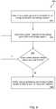
- FIG. 9 depicts a flow diagram of a method 800 for controlling operation of an energy generation and storage system using a multi-layer architecture is provided according to example embodiments of the present disclosure. It should be appreciated that the method 800 can be implemented using the multi-layer architecture 200 discussed above with reference to FIGS. 3-6 .
- FIG. 9 depicts steps performed in a particular order for purposes of illustration and discussion. Those of ordinary skill in the art, using the disclosures provided herein, will understand that various steps of the method 800 may be adapted, modified, rearranged, performed simultaneously or modified in various ways without deviating from the scope of the present disclosure.
- the method 800 includes determining, by one or more control devices, a power or energy generation schedule for the energy generation and storage system at a first layer of the multi-layer architecture.
- a scheduling controller implemented at a first layer can determine the power or energy generation schedule based on various input data.
- the input data can include market data, environmental data (e.g., weather), feedback data indicative of a current state or health of one or more assets of the energy generation and storage system, and/or penalty/incentive data associated with one or more grid service requests. It should be appreciated, however, that the input data can include any data that can be used to determine the power generation schedule for the energy generation and storage system.
- the method 800 includes determining, by one or more control devices, a power or energy setpoint for the energy generation and storage system based, at least in part, on the power or energy generation schedule determined at (802).
- a dispatch controller implemented at a second layer of the multi-layer architecture can determine the power setpoint based on various input data.
- the input data can include the power generation schedule determined at (802), real-time market data, real-time environmental data (e.g., weather), feedback data indicative of a current state or health of one or more assets of the energy generation and storage system, and/or penalty/incentive data associated with one or more grid service requests.
- the input data can include any data that can be used to determine the power or energy generation schedule for the energy generation and storage system.
- the method 800 includes determining whether the power or energy setpoint determined at (804) violates one or more constraints.
- a configuration controller implemented at a third layer of the multi-layer architecture can determine whether the power setpoint determined at (804) violates the one or more constraints.
- the one or more constraints can be associated with the one or more assets of the energy generation and storage system.
- the one or more constraints can be indicative of operating limits(e.g., rated voltage, rated current, etc.) associated with the one or more assets.
- the one or more constraints can be associated with the grid services (e.g., power firming) the energy generation and storage system is currently committed to provide. If the power or energy setpoint determined at (804) does not violate the one or more constraints, the method 800 proceeds to (808). Otherwise, the method 800 reverts to (804). It should be appreciated that multiple iterations of steps (804) and (806) may be performed until a power or energy setpoint is determined that does not violate the one or more constraints.
- the method 800 can include providing a notification indicative of the power or energy setpoint determined at (804) violating the one or more constraints.
- the notification can comprise a visual notification or audible notification. In this manner, one or more persons receiving the notification can become apprised of the power setpoint violation.
- the method 800 includes controlling, by one or more control devices, operation of energy storage system based, at least in part, on the power or energy setpoint.
- the configuration controller implemented at the third layer of the multi-layer architecture can be configured to generate one or more control actions associated with adjusting operation of one or more assets of the system based, at least in part, on the power or energy setpoint. In this manner, operation of the one or more assets of the system can be adjusted to reduce or eliminate deviations from the power or energy generation schedule that result in penalties (e.g., monetary losses, energy losses, power losses, etc.).
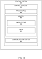
- FIG. 10 depicts a block diagram of an example control system 900 that may be used by a distributed control system, or other systems to implement methods and systems according to example embodiments of the present disclosure.
- the control system 900 can include one or more control device(s) 902.
- the control device(s) 902 may include one or more processors 904 and one or more memory devices 906.
- the processor(s) 904 can include any suitable processing device, such as a microprocessor, microcontroller, integrated circuit, logic device, or other suitable processing device.
- the memory device(s) 906 can include one or more computer-readable media, including, but not limited to, non-transitory computer-readable media, RAM, ROM, hard drives, flash drives, or other memory devices.
- the memory device(s) 906 can store information accessible by the one or more processor(s) 904, including computer-readable instructions 908 that may be executed by the processor(s) 904.
- the instructions 908 may be any set of instructions that when executed by the processor(s) 904, cause the processor(s) 904 to perform operations.
- the instructions 908 may be software written in any suitable programming language or may be implemented in hardware.
- the instructions 908 may be executed by the processor(s) 904 to cause the processor(s) 904 to perform operations, such as implementing one or more of the processes mentioned above.
- the memory device(s) 904 may further store data 910 that may be accessed by the processor(s) 904. It should be appreciated that data 610 may include one or more table(s), function(s), algorithm(s), model(s), equation(s), etc. according to example embodiments of the present disclosure.
- the control device(s) 902 can also include a communication interface 912 used to communicate, for example, with the other components of system 900.
- the communication interface 912 may include any suitable components for interfacing with one or more network(s), including for example, transmitters, receivers, ports, controllers, antennas, or other suitable components.
Landscapes
- Engineering & Computer Science (AREA)
- Business, Economics & Management (AREA)
- Power Engineering (AREA)
- Physics & Mathematics (AREA)
- General Physics & Mathematics (AREA)
- Theoretical Computer Science (AREA)
- Economics (AREA)
- Human Resources & Organizations (AREA)
- Strategic Management (AREA)
- Automation & Control Theory (AREA)
- Marketing (AREA)
- Entrepreneurship & Innovation (AREA)
- Tourism & Hospitality (AREA)
- General Business, Economics & Management (AREA)
- Game Theory and Decision Science (AREA)
- Development Economics (AREA)
- Health & Medical Sciences (AREA)
- Operations Research (AREA)
- Quality & Reliability (AREA)
- Electromagnetism (AREA)
- Radar, Positioning & Navigation (AREA)
- General Engineering & Computer Science (AREA)
- Public Health (AREA)
- Water Supply & Treatment (AREA)
- General Health & Medical Sciences (AREA)
- Primary Health Care (AREA)
- Educational Administration (AREA)
- Supply And Distribution Of Alternating Current (AREA)
Abstract
Description
- The present subject matter relates generally to energy generation and storage systems and more particularly, to systems and methods for controlling operation of energy generation and storage systems.
- Power generation facilities can be configured to deliver various grid services for revenue generation. For instance, power generations systems, such as renewable energy plants, can be configured to respond to requests for grid services, such as peak shaving, frequency response, ramp rate control, purchasing and selling of energy, load following, energy arbitrage, and other grid services. Typically, power generation facilities provide grid services in modal fashion such that the power generation facility responds to power demands for a single grid service at a time.
- Energy storage systems have become increasingly used to deliver power to utility grids either as part of standalone energy storage systems or as part of a renewable energy farm (e.g., a wind farm or solar farm) with an integrated energy storage system. Energy storage systems can include one or more battery banks or other energy storage devices that can be coupled to the grid via a suitable power converter. Energy storage systems are unique in that energy storage systems have the ability to both deliver and reserve energy for particular grid services.
- Aspects and advantages of embodiments of the present disclosure will be set forth in part in the following description, or may be learned from the description, or may be learned through practice of the embodiments.
- In one aspect, a method for controlling an energy generation and storage system using a multi-layer architecture is provided. The method includes determining, by one or more control devices, a power or energy generation schedule for the energy generation and storage system at a first layer of the multi-layer architecture. The method further includes determining, by the one or more control devices, a power setpoint for the energy generation and storage system at a second layer of the multi-layer architecture. The power or energy setpoint is based, at least in part, on the power or energy generation schedule. The method further includes controlling, by the one or more control devices, operation of the energy generation and storage system based, at least in part, on the power or energy setpoint.
- In another aspect, a control system for controlling operation of an energy generation and storage system using a multi-layer architecture is provided. The control system includes one or more control devices configured to perform operations. The operations include determining a power or energy generation schedule at a first layer of the multi-layer architecture. The operations can further include determining a power or energy setpoint for the energy generation and storage system at a second layer of the multi-layer architecture. The power or energy setpoint can be based, at least in part, on the power or energy generation schedule. The operations can further include controlling operation of the energy generation and storage system based, at least in part, on the power or energy setpoint.
- In yet another aspect, a multi-layer architecture for controlling operation of an energy generation and storage system is provided. The multi-layer architecture includes a first layer. The first layer includes one or more control devices configured to determine a power or energy generation schedule for the energy generation and storage system. The multi-layer architecture further includes a second layer. The second layer includes one or more control devices configured to determine a power or energy setpoint for the energy generation and storage system based, at least in part, on the power or energy generation schedule. The multi-layer architecture further includes a third layer. The third layer includes one or more control devices configured to control operation of the energy generation and storage system based, at least in part, on the power or energy setpoint.
- Variations and modifications can be made to these example aspects of the present disclosure. These and other features, aspects and advantages of various embodiments will become better understood with reference to the following description and appended claims. The accompanying drawings, which are incorporated in and constitute a part of this specification, illustrate embodiments of the present disclosure and, together with the description, serve to explain the related principles.
- Detailed discussion of embodiments directed to one of ordinary skill in the art are set forth in the specification, which makes reference to the appended figures, in which:
-
FIG. 1 depicts an energy generation and storage system according to example embodiments of the present disclosure; -
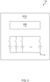
FIG. 2 depicts a block diagram of an energy storage asset of the energy generation and storage system ofFIG.1 according to example embodiments of the present disclosure; -
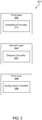
FIG. 3 depicts a multi-layer architecture used to control operation of an energy generation and storage system according to example embodiments of the present disclosure; -
FIG. 4 depicts a scheduling controller of the multi-layer architecture ofFIG. 2 according to example embodiments of the present disclosure; -
FIG. 5 depicts a dispatch controller of the multi-layer architecture ofFIG. 2 according to example embodiments of the present disclosure; -
FIG. 6 depicts a configuration controller of the multi-layer architecture ofFIG. 2 according to example embodiments of the present disclosure; -
FIG. 7 depicts a graphical representation of implementation of the multi-layer architecture ofFIG. 3 according to example embodiments of the present disclosure; -
FIG. 8 depicts a system for controlling operation of an energy generation and storage system according to example embodiments of the present disclosure; -
FIG. 9 depicts a flow diagram of a method for controlling operation of an energy generation and storage system according to example embodiments of the present disclosure; and -
FIG. 10 depicts a block diagram of a control system according to example embodiments of the present disclosure. - Reference now will be made in detail to embodiments of the invention, one or more examples of which are illustrated in the drawings. Each example is provided by way of explanation of the invention, not limitation of the invention. In fact, it will be apparent to those skilled in the art that various modifications and variations can be made in the present invention without departing from the scope or spirit of the invention. For instance, features illustrated or described as part of one embodiment can be used with another embodiment to yield a still further embodiment. Thus, it is intended that the present invention covers such modifications and variations as come within the scope of the appended claims and their equivalents.
- Example aspects of the present disclosure are directed to systems and methods for controlling operation of an energy generation and storage system using a multi-layer architecture. In some implementations, the multi-layer architecture can include three separate layers (e.g., first layer, second layer, and third layer). The first layer can include a scheduling controller configured to determine a power or energy generation schedule for the energy generation and storage system. The second layer can include a dispatch controller configured to determine a power or energy setpoint for the power generation and storage system based, at least in part, on the power or energy generation schedule. The third layer can include a configuration controller configured to control one or more assets (e.g., energy generation assets and/or energy storage assets) in real time and account for real time constraints, such as those imposed by the grid operator and not visible to the dispatch controller.
- The scheduling controller can be configured to determine a power or energy generation schedule that maximizes net revenue (e.g. gross, penalties, cost of system degradation) based on various input data. For instance, the input data can include forecasted or actual market data, forecasted power generation data, environmental data, operational feedback data (e.g., state-of-charge), or any other suitable data that can be used to determine the power or energy generation schedule. The scheduling controller can be configured to determine a power generation schedule that satisfies one or more constraints of a grid or market service to which the energy generation and storage system is committed. For example, the scheduling controller can be configured to determine a power generation schedule that allows the energy generation and storage system to operate in a firm manner despite the unpredictable nature of the energy generation assets (e.g., solar, wind, etc.) of the system. The scheduling controller can also be used to generate a bid in the day or hours ahead timeframe in the energy, capacity or ancillary service markets. For instance, the scheduling controller can be configured to take into account forecasts for day ahead prices and forecasts for wind and solar generation and determine a bid schedule that maximizes revenue in the day ahead energy market. In this instance, the cleared bid from the energy market will be passed on to the dispatch controller as the generation schedule. The scheduling controller can similarly be configured for several use cases including, but not limited to, firming and load following.
- The dispatch controller can be configured to determine a power or energy setpoint for the energy generation and storage system that further maximizes the system's net revenue and is based, at least in part, on the power generation schedule determined by the scheduling controller. In some instances, the amount of power or energy the generation assets output during a portion of the power or energy generation schedule can be less than the amount of power or energy required by the grid service request due to inaccuracies in predicting in advanced the amount of power that will be generated during scheduling. In such instances, the power or energy setpoint determined by the dispatch controller can recommend the energy storage assets (e.g., batteries) discharge to provide the additional power or energy needed to meet the power or energy demands of the grid service request. In this manner, deviations between the amount of power or energy the system provides and the amount of power or energy the system is committed to provide according to the power generation schedule can be avoided. More specifically, deviations from the power generation schedule that result in penalties (e.g., monetary losses, energy losses, power losses, etc.) can be avoided.
- However, in some instances, the amount of power or energy the generation assets output during a portion of the power or energy generation schedule can be greater than the amount of power or energy required by the grid service request. In such instances, the power or energy setpoint determined by the dispatch controller can recommend the excess power or energy generated by the generation assets be used to charge the storage assets of the system. In this manner, the excess power or energy generated by the generation assets can be used in a more efficient manner. In addition to using the energy storage assets, the power generation assets can also be used to respond to a power setpoint when needed, as determined by the dispatch controller or configured controller. The dispatch controller can also be configured to generate power or energy bids in the real time market. The real time market bids are typically requested a few minutes to a few hours in advance of the actual generation. The dispatch controller can take into account better near term forecasts for energy production and price to determine the real time bid to maximize revenue. In this instance, the cleared bid is passed on to the third layer which is the configuration controller as the power or energy setpoint. The dispatch controller can similarly be configured for several use cases including but not limited to firming and load following.
- The configuration controller can be configured to determine whether the power or energy setpoint determined by the dispatch controller violates one or more constraints. In some implementations, the one or more constraints can be associated with the grid regulations. Alternatively or additionally, the one or more constraints can be associated with one or more assets (e.g., energy generation assets and/or energy storage assets) of the system. Furthermore, an external authority (e.g., grid operator), can impose a constraint on the system by commanding it to output a certain power or respond to a grid event (e.g., frequency event).
- When the configuration controller determines the power or energy setpoint violates the one or more constraints, the configuration controller does not adjust operation of the energy generation and storage system according to the power or energy setpoint recommended by the dispatch controller at the second layer of the architecture. In contrast, when the configuration controller determines the power or energy setpoint does not violate the one or more constraints, the configuration controller generates one or more control actions associated with controlling operation of the energy generation and storage system based, at least in part, on the power or energy setpoint. More specifically, the one or more control actions can be associated with adjusting the power or energy setpoint for the assets (e.g., energy generation asset and/or energy storage assets) of the energy generation and storage system. In this manner, operation of the energy generation and storage system can be controlled (e.g., adjusted) to avoid deviations in the power generation schedule the system is currently committed to provide. As such, deviations from the power generation schedule that result in penalties (e.g., monetary losses, energy losses, power losses, etc.) can be reduced or eliminated, thus maximizing net revenue of the system. The configuration controller also manages grid code compliance requirements and is authorized to deviate from the power or energy setpoint if such deviation is required to meet grid code compliance requirements.
- The present disclosure provides numerous technical benefits. For instance, controlling operation of the energy generation and storage system using the multi-layer architecture allows the system to operate in a more efficient manner and achieve maximum net revenue across its grid service requests while maintaining grid compliance. As mentioned above, the system can be controlled such that the energy storage assets discharge when the amount of power the generation assets output is less than the amount of power required by the grid service request. Thus, deviations from the power generation schedule that result in penalties (e.g., monetary losses, energy losses, power losses, etc.) can be avoided. Additionally, the system can be controlled such that the energy storage assets charge when the amount of power the generation assets output is greater than the amount of power required by the grid service request. In this manner, excess power generated by the generation assets can be recycled. The multi-layer architecture ensures that the scheduling controller can make power and energy commitments days or hours in advance where required by the grid operator. This architecture also allows for the dispatch controller to deviate from this advance commitment based on near term forecasts when the costs or penalties associated with such deviation is lesser than the rewards. The last layer of the multi-layer architecture, the configuration controller, manages the assets in real time and ensures real time constraints and grid compliance requirements are met.
- Referring now to the Figures,
FIG. 1 depicts an energy generation andstorage system 100 according to example embodiments of the present disclosure. The energy generation andstorage system 100 includes one or moreenergy generation assets 102 and one or moreenergy storage assets 104. In some implementations, the energy generation andstorage system 100 can be a standalone power system. In alternative implementations, the energy generation andstorage system 100 can be implemented as part of a large-scale renewable energy system, such as wind farm or solar farm. - The energy generation asset(s) 102 can include any number of energy generating components. For example, the energy generation asset(s) 102 can include, without limitation, gas engine generators, gas turbines, wind turbines, solar cells, steam turbines, hydroelectric generators, nuclear power assets, or other devices capable of generating energy.
- Referring briefly now to
FIG. 2 , the energy storage asset(s) 104 can include any number of energy storing components. For example, the energy storage asset(s) 104 can include a battery energy storage system (BESS) 110. The BESS 110 can include one or more batteryenergy storage devices 112, such as battery cells or battery packs. The batteryenergy storage devices 112 can contain one or more sodium nickel chloride batteries, sodium sulfur batteries, lithium ion batteries, nickel metal hydride batteries, or other similar devices. The batteryenergy storage units 112 can be coupled to a switching element (e.g. one or more contactors) selectively operable to couple theenergy storage units 112 to thesystem 100. Although batteryenergy storage units 112 include individual battery cells coupled to a switching element, it will be appreciated that batteryenergy storage units 112 can include multiple battery cells coupled to the switching element. In addition, the present disclosure is discussed with reference to a battery energy storage system for purposes of illustration and discussion, those of ordinary skill in the art, using the disclosures provided herein, should understand that other energy storage devices (e.g. capacitors, fuel cells, etc.) can be used without deviating from the scope of the present disclosure. - The BESS 110 can include a battery management system (BMS) 115. The
BMS 115 can include one or more electronic devices that monitor one or more of the batteryenergy storage units 112, such as by protecting the battery energy storage unit from operating outside a safe operating mode, monitoring a state of the battery energy storage unit, calculating and reporting operating data for the battery energy storage unit, controlling the battery energy storage unit environment, and/or any other suitable control actions. For example, in some embodiments, theBMS 115 is configured to monitor and/or control operation of one or moreenergy storage units 112. TheBMS 115 can be, for example, a logic controller implemented purely in hardware, a firmware-programmable digital signal processor, or a programmable processor-based software-controlled computer. - Referring again to
FIG. 1 , thesystem 100 can also include one or more control devices (e.g., controller) configured to monitor and/or control various aspects of the energy generation andstorage system 100. For instance, as shown inFIG. 1 , thesystem 100 can include a first control device 170 configured to control operation of the energy generation asset(s) 102. Additionally, thesystem 100 can include asecond control device 172 configured to control operation of the energy storage asset(s) 104. For instance, thecontrol devices 170, 172 can control an amount of power the energy generation asset(s) 102 and/or energy storage asset(s) 104 provide to a power grid 180. - Referring now to
FIG. 3 , a block diagram of amulti-layer architecture 200 that can be used to control operation of an energy generation and storage system is provided according to example embodiments of the present disclosure. As shown, themulti-layer architecture 200 includes afirst layer 202, asecond layer 204, and athird layer 206. It should be appreciated, however, that the multi-layer architecture can include more or fewer layers. For instance, in some embodiments, themulti-layer architecture 200 can include only two layers. - As shown, the
first layer 202 can include ascheduling controller 210, thesecond layer 204 can include adispatch controller 220, and thethird layer 206 can include aconfiguration controller 230. It should be appreciated that thecontrollers different layers multi-layer architecture 200 can include software configured to be stored in a processor readable storage device to program a processor to perform functions described herein. - Referring now to
FIG. 4 , thescheduling controller 210 can be configured to access, obtain, or receive various types ofinput data 300. For example, thescheduling controller 210 can obtainmarket data 302 that describes various market inputs. In some implementations, themarket data 302 can include data that describes day ahead market prices (e.g., for energy and/or ancillary services), fuel prices, or other prices for various items that may be bought or sold from a market (e.g., an energy market associated with the grid). Themarket data 302 may include forecasted or actual data. Alternatively or additionally, themarket data 302 can include or convey one or more grid service requests. - In some implementations, the
scheduling controller 210 can determine one or more grid service requests based on the forecasted or actualmarket input data 302. The grid service requests can be requests for beneficial services, such as peak shaving, frequency response, ramp rate control, purchasing and selling of energy, load following, energy arbitrage, power firming, and other grid services. The grid service requests can specify a requested amount of power and/or a requested duration. The grid service requests or other associated requests can specify certain performance parameters that are mandatory or requested (e.g., supplied power should be within a certain frequency range). If the supplied grid service does not meet the performance parameters, the potential revenue can be decreased by some factor. - In some implementations, the
input data 300 includesenvironmental data 304 that describes various environmental conditions. For instance, theenvironmental input data 304 can include data that describes an ambient temperature at one or more of the energy generation and/or storage assets, an ambient humidity at one or more of the energy generation and/or storage assets, an ambient pressure at one or more of the energy generation and/or storage assets, weather forecasts for locations of one or more of the energy generation and/or storage assets, hazardous conditions potentially damaging to assets or preventative of maintenance thereto, or other environmental conditions. - In some implementations, the
input data 300 can include systemoperational feedback data 306 indicative of performance of one or more assets (e.g., energy generating assets and/or energy storage assets) of the energy generation and storage system. For example, thefeedback data 306 can indicate state of asset data (e.g., presently observed physical measurements) that describes the status of various operational parameters or other current conditions of the one or more assets of the energy generation and storage system. - As an example, one or more sensors of the energy generation and storage system can provide state of asset data to the
scheduling controller 210. For instance, the state of asset data can describe a current power output setpoint of one or more energy generation assets; a current effective power output by the generation asset(s); a current state of health of the energy generation asset(s); and/or a current RPM for one or more energy generation assets that include moving parts. Alternatively or additionally, the state of asset data can include one or more temperature readings associated with the energy generation asset(s); an emissions status for the energy generation asset(s); a current and/or expected efficiency for the energy generation asset(s); or any other suitable data indicative of a state or health of the energy generation asset(s). - As another example, the state of asset data obtained from the one or more sensors can describe a current power output setpoint of one or more energy storage assets; a current effective power output by the energy storage asset(s); a current state of health of the energy storage asset(s); and/or a current state of charge of the energy storage asset(s). Alternatively or additionally, the state of asset data can include one or more temperature readings associated with the energy storage asset(s).
- In some implementations, the
input data 300 can include penalty/incentive data 308. For instance, thedata 308 can be indicative of a penalty (e.g., monetary losses, energy losses, power losses, etc.) associated with non-compliance of one or more constraints of a grid services request. Alternatively or additionally, thedata 308 can be indicative of an incentive (e.g., monetary) associated with compliance of the one or more constraints of the grid service request. - In some implementations, the
input data 300 can include forecastpower generation data 309 associated with the energy generation asset(s) 102 (FIG. 1 ) of the system 100 (FIG. 1 ). For instance, the forecastpower generation data 309 can indicate an amount of power the energy generation asset(s) 102 is predicted to generate over the next day. It should be appreciated, however, that thepower generation data 309 can indicate an amount of power the energy generation asset(s) 102 are predicted (e.g., forecasted) to generate over any suitable amount of time. - In some implementations, the
scheduling controller 210 can determine a power orenergy generation schedule 310 to commit to the grid authority based, at least in part, on theinput data 300. For instance, thescheduling controller 210 can be configured to determine apower generation schedule 310 that satisfies one or more constraints of a grid services request. In this manner, economic losses (e.g., lost revenue) associated with operating the energy generation and storage system to meet the grid services request can be reduced or eliminated. - In some implementations, the
scheduling controller 210 can be configured to determine the power orenergy generation schedule 310 multiple times each day. For example, thescheduling controller 210 can be configured to determine thepower generation schedule 310 after a predetermined amount of time (e.g., 1 hour) has lapsed since thepower generation schedule 310 was last determined. In this manner, thepower generation schedule 310 can be updated to reflect fluctuations (e.g., changes) to theinput data 300. In some implementations, thepower generation schedule 310 determined by thescheduling controller 210 can be provided to a grid operator/market authority 311 for approval. Furthermore, upon receiving approval, thepower generation schedule 310 can be provided to thesecond layer 204 of the multi-layer architecture, which will be discussed below in more detail. - Referring now to
FIG. 5 , thedispatch controller 220 included at thesecond layer 204 of themulti-layer architecture 200 can be configured to access, obtain, or receive various types ofinput data 400. For example, theinput data 400 can include data associated with thepower generation schedule 310 determined by the scheduling controller 210 (FIG. 3 ) at the first layer 202 (FIG. 3 ) of themulti-layer architecture 200. For instance, the data associated with thepower generation schedule 310 can indicate an amount of power the system is committed to provide over a predetermined amount of time, such as one hour. - In some implementations, the
input data 400 can include forecasted or actualmarket input data 402 that describes real-time market prices (e.g., for energy and/or ancillary services) for various items that may be bought or sold from a market, such as an energy market associated with the grid. Alternatively or additionally, theinput data 400 can includeenvironmental data 404 that includes real-time weather forecast data for an area or region in which the energy generation and storage system is located. - In some implementations, the
input data 400 can include thefeedback data 306 indicative of performance of the energy generation asset(s) 102 (FIG. 1 ) and/or the energy storage assets(s) 104 (FIG. 1 ). For example, thefeedback data 306 can indicate state of asset data (e.g., presently observed physical measurements) that describes the status of various operational parameters or other current conditions at the energy generation asset(s) 102 and/or the energy storage asset(s) 104. - In some implementations, the
input data 400 can include forecastpower generation data 405 associated with the energy generation asset(s) 102 (FIG. 1 ) of the system 100 (FIG. 1 ). For instance, the forecastpower generation data 405 can indicate an amount of power the energy generation asset(s) 102 is predicted to generate over the next few hours. It should be appreciated, however, that thepower generation data 405 included asinput data 400 for thedispatch controller 220 can be more accurate compared to the power generation data 309 (FIG 4 ) included as input data 300 (FIG. 4 ) for the scheduling controller 210 (FIG. 4 ). - The
dispatch controller 220 can be configured to determine a power or energy setpoint for one or more assets (e.g., energy generation assets and/or energy storage assets) of the energy generation and storage system. In some implementations, the power setpoint can include a split value indicative of a power split between an energy generation asset (e.g., wind, solar, etc.) of the system and an energy storage asset (e.g., battery) of the system. It should be appreciated that the power or energy setpoint for a particular asset (e.g. generation asset or storage asset) can be positive or negative. A positive power setpoint for an asset indicates the asset is providing power to the load (e.g., grid) or other components of the system. In contrast, a negative power setpoint for an asset indicates the asset is receiving power (e.g., charging) from the load (e.g., grid) or other components of the system. - In some implementations, the power or
energy setpoint 406 determined by thedispatch controller 220 can be provided to the grid operator/market authority 311 for approval. Furthermore, upon receiving approval, the power orenergy setpoint 406 can be provided to the third layer 206 (FIG. 3 ) of the multi-layer architecture 200 (FIG. 3 ), which will be discussed below in more detail - Referring now to
FIG. 6 , theconfiguration controller 230 can be configured to access, obtain, or receive various types ofinput data 500. For example, theinput data 500 can include thepower setpoint 406 determined by the dispatch controller 220 (FIG. 5 ) at thesecond layer 204 of themulti-layer architecture 200. Additionally, theinput data 500 can includeconstraint data 502 provided by a grid operator or other external source. In some implementations, theconstraint data 502 can be indicative of one or more constraints associated with the grid service request to which the energy generation and storage system is currently committed. Alternatively or additionally, theconstraint data 502 can be indicative of one or more constraints associated with one or more assets (e.g., energy generation asset and/or energy storage assets) of the system. - The
configuration controller 230 can be configured to determine whether thepower setpoint 406 recommended by the dispatch controller 220 (FIG. 5 ) at the second layer 204 (FIG. 5 ) violates the one or more constraints. When theconfiguration controller 230 determines thepower setpoint 406 violates the one or more constraints, theconfiguration controller 230 does not adjust operation of the energy generation and storage system according to thepower setpoint 406. In contrast, when theconfiguration controller 230 determines thepower setpoint 406 does not violate the one or more constraints, theconfiguration controller 230 generates one ormore control actions 504 associated with controlling operation of the energy generation and storage system based, at least in part, on the power orenergy setpoint 406. More specifically, the one ormore control actions 504 can be associated with adjusting the power or energy setpoint for the assets (e.g., energy generation asset and/or energy storage assets) of the energy generation and storage system. In this manner, operation of the energy generation and storage system can be controlled (e.g., adjusted) to avoid deviations between the amount of power or energy the system outputs and the amount of power the system is committed to provide according to the power generation schedule. More specifically, deviations from the power generation schedule resulting in penalties (e.g., monetary loss, energy loss, power loss, etc.) can be reduced or eliminated. - Referring now to
FIG. 7 , a graphical representation of an implementation of the multi-layer architecture 200 (FIG. 3 ) for a power generation and storage system committed to a grid service (e.g., power firming) according to example embodiments of the present disclosure.Curve 600 indicates a forecasted output of the energy generation asset(s) 102 (FIG. 1 ) of the power generation andstorage system 100. As shown, the graphical representation depicts a first interval oftime 610 and a second interval oftime 620 that occurs after the first interval oftime 610. The first interval oftime 610 and thesecond time interval 620 each span one hour. However, it should be appreciated, that the first andsecond time intervals -
Line 630 corresponds to the power generation schedule the energy generation and storage system is, according to the power generation schedule 310 (FIG. 4 ), committed to provide during the first interval oftime 610. As shown, the energy generation and storage system is committed to provide a greater amount of power than the energy generation asset(s) 102 of thesystem 100 are forecasted to provide during the first interval oftime 610. Thus, in order to ensure an amount of power or energy the system output does not deviate (e.g., vertical space betweencurve 600 and line 630) from an amount of power the system is committed to provide according to the power generation schedule, the dispatch controller 220 (FIG. 5 ) implemented at the second layer 204 (FIG. 5 ) of themulti-layer architecture 200 can determine a power or energy setpoint for the system 100 (FIG. 1 ). More specifically, thedispatch controller 220 can determine a power or energy setpoint for thesystem 100 such that the energy storage asset(s) 104 of thesystem 100 provides an additional amount of power that is needed to ensure the energy generation and storage system 100 (that is, the energy generation asset(s) 102 and the energy storage asset(s) 104) provides the requisite amount of power according to the power generation schedule. -
Line 640 corresponds to a predicted power generation schedule (e.g., not yet committed to grid authority) for the energy generation and storage system during the second interval oftime 620. As shown, the predicted power generation schedule is less than the forecasted output of the energy generation asset(s) 102 (FIG. 1 ) of thesystem 100. As such, thedispatch controller 220 can determine a power or energy setpoint for thesystem 100 such that excess power generated by the generation asset(s) 102 can be used to recharge the energy storage asset(s) 104. In this manner, themulti-layer architecture 200 of the present disclosure reduces or eliminates the occurrence of penalties (e.g., monetary losses, energy losses, power losses, etc.) associated with operation of the energy generation and storage system. - Referring now to
FIG. 8 , asystem 700 for controlling operation of an energy generation and storage system using a multi-layer architecture (e.g., multi-layer architecture ofFIGS. 3-6 ) is provided according to example embodiments of the present disclosure. As shown, thesystem 700 can include afirst control device 710 configured to implement the first layer 202 (FIG. 4 ) of themulti-layer architecture 200. For instance, thefirst control device 710 can be configured to implement thescheduling controller 210 included in thefirst layer 202. In this manner, thefirst control device 710 can access or obtain input data (e.g., market data, environmental data, feedback data, penalty/incentive data) that can be used to determine a power or energy generation schedule for the energy generation and storage system. - In some implementations, the
system 700 can include asecond control device 720 configured to implement the second layer 204 (FIG. 5 ) of themulti-layer architecture 200. For instance, thesecond control device 720 can be configured to implement thedispatch controller 220 included in thesecond layer 204. In this manner, thesecond control device 720 can access or obtain input data (e.g., power generation schedule, market data, environmental data, feedback data, penalty/incentive data, etc.) that can be used to determine a power or energy setpoint for the energy generation and storage system. More specifically, the second control device can be configured to determine a power setpoint for one or more assets (e.g., generation asset and/or storage asset) to reduce or eliminate deviations from the power or energy generation schedule that can result in penalties (e.g. monetary losses, energy losses, power losses, etc.). - In some implementations, the
system 700 can include athird control device 730 configured to implement the third layer 206 (FIG. 6 ) of themulti-layer architecture 200. For instance, thethird control device 730 can be configured to implement theconfiguration controller 230 included in thethird layer 206. In this manner, thethird control device 730 can be configured to determine whether the power or energy setpoint determined by thesecond control device 720 violates one or more constraints. In some implementations, the one or more constraints can be associated with the grid service request to which the energy generation and storage system is committed. Alternatively or additionally, the one or more constraints can be operating constraints (e.g., rated voltage) of one or more assets of the energy generation and storage system. - In some implementations, the
control devices system 700 can be configured to implement therespective layers FIG. 3 ) of themulti-layer architecture 200 at different frequencies. For instance, thefirst control device 710 can be configured to implement thescheduling controller 210 at a first frequency (e.g., once every hour). - The
second control device 720 can be configured to implement thedispatch controller 220 at a second frequency that is different than the first frequency. More specifically, the second frequency can be greater than the first frequency. In this manner, thesecond control device 720 can be configured to implement thedispatch controller 220 more frequently than thefirst control device 710 implements thescheduling controller 210. - The
third control device 730 can be configured to implement theconfiguration controller 230 at a third frequency that is different than the first frequency. More specifically, the third frequency can be greater than the second frequency. In this manner, thethird control device 730 can be configured to implement theconfiguration controller 230 more frequently than thesecond control device 720 implements thedispatch controller 220. - Although the
system 700 ofFIG. 7 depicts eachlayer FIG. 3 ) of themulti-layer architecture 200 being implemented in discrete control devices, it should be appreciated that one ormore layers second control device 720 can be configured to implement both thesecond layer 204 and thethird layer 206 of themulti-layer architecture 200. It should also be appreciated that thecontrol devices system 700 can be located at any suitable location. For instance, in some implementations, thefirst control device 710 can be a server or cloud computing device provided at a location that is remote relative to the energy generation asset(s) and energy storage asset(s) of the system. In some implementations, thesecond control device 720 can be configured to facilitate communication between thefirst control device 710 and thethird device 730. Alternatively or additionally, thethird control device 730 correspond to the control devices 170, 172 (FIG. 1 ) of the energy generation and storage system 100 (FIG. 1 ). -
FIG. 9 depicts a flow diagram of amethod 800 for controlling operation of an energy generation and storage system using a multi-layer architecture is provided according to example embodiments of the present disclosure. It should be appreciated that themethod 800 can be implemented using themulti-layer architecture 200 discussed above with reference toFIGS. 3-6 .FIG. 9 depicts steps performed in a particular order for purposes of illustration and discussion. Those of ordinary skill in the art, using the disclosures provided herein, will understand that various steps of themethod 800 may be adapted, modified, rearranged, performed simultaneously or modified in various ways without deviating from the scope of the present disclosure. - At (802), the
method 800 includes determining, by one or more control devices, a power or energy generation schedule for the energy generation and storage system at a first layer of the multi-layer architecture. In example embodiments, a scheduling controller implemented at a first layer can determine the power or energy generation schedule based on various input data. For instance, the input data can include market data, environmental data (e.g., weather), feedback data indicative of a current state or health of one or more assets of the energy generation and storage system, and/or penalty/incentive data associated with one or more grid service requests. It should be appreciated, however, that the input data can include any data that can be used to determine the power generation schedule for the energy generation and storage system. - At (804), the
method 800 includes determining, by one or more control devices, a power or energy setpoint for the energy generation and storage system based, at least in part, on the power or energy generation schedule determined at (802). In example embodiments, a dispatch controller implemented at a second layer of the multi-layer architecture can determine the power setpoint based on various input data. For instance, the input data can include the power generation schedule determined at (802), real-time market data, real-time environmental data (e.g., weather), feedback data indicative of a current state or health of one or more assets of the energy generation and storage system, and/or penalty/incentive data associated with one or more grid service requests. It should be appreciated, however, that the input data can include any data that can be used to determine the power or energy generation schedule for the energy generation and storage system. - At (806), the
method 800 includes determining whether the power or energy setpoint determined at (804) violates one or more constraints. In example embodiments, a configuration controller implemented at a third layer of the multi-layer architecture can determine whether the power setpoint determined at (804) violates the one or more constraints. - In some implementations, the one or more constraints can be associated with the one or more assets of the energy generation and storage system. For instance, the one or more constraints can be indicative of operating limits(e.g., rated voltage, rated current, etc.) associated with the one or more assets. Alternatively or additionally, the one or more constraints can be associated with the grid services (e.g., power firming) the energy generation and storage system is currently committed to provide. If the power or energy setpoint determined at (804) does not violate the one or more constraints, the
method 800 proceeds to (808). Otherwise, themethod 800 reverts to (804). It should be appreciated that multiple iterations of steps (804) and (806) may be performed until a power or energy setpoint is determined that does not violate the one or more constraints. In some implementations, themethod 800 can include providing a notification indicative of the power or energy setpoint determined at (804) violating the one or more constraints. In example embodiments, the notification can comprise a visual notification or audible notification. In this manner, one or more persons receiving the notification can become apprised of the power setpoint violation. - At (808), the
method 800 includes controlling, by one or more control devices, operation of energy storage system based, at least in part, on the power or energy setpoint. In some implementations, the configuration controller implemented at the third layer of the multi-layer architecture can be configured to generate one or more control actions associated with adjusting operation of one or more assets of the system based, at least in part, on the power or energy setpoint. In this manner, operation of the one or more assets of the system can be adjusted to reduce or eliminate deviations from the power or energy generation schedule that result in penalties (e.g., monetary losses, energy losses, power losses, etc.). -
FIG. 10 depicts a block diagram of anexample control system 900 that may be used by a distributed control system, or other systems to implement methods and systems according to example embodiments of the present disclosure. As shown, thecontrol system 900 can include one or more control device(s) 902. The control device(s) 902 may include one ormore processors 904 and one ormore memory devices 906. The processor(s) 904 can include any suitable processing device, such as a microprocessor, microcontroller, integrated circuit, logic device, or other suitable processing device. The memory device(s) 906 can include one or more computer-readable media, including, but not limited to, non-transitory computer-readable media, RAM, ROM, hard drives, flash drives, or other memory devices. - The memory device(s) 906 can store information accessible by the one or more processor(s) 904, including computer-
readable instructions 908 that may be executed by the processor(s) 904. Theinstructions 908 may be any set of instructions that when executed by the processor(s) 904, cause the processor(s) 904 to perform operations. Theinstructions 908 may be software written in any suitable programming language or may be implemented in hardware. In some embodiments, theinstructions 908 may be executed by the processor(s) 904 to cause the processor(s) 904 to perform operations, such as implementing one or more of the processes mentioned above. The memory device(s) 904 may further storedata 910 that may be accessed by the processor(s) 904. It should be appreciated thatdata 610 may include one or more table(s), function(s), algorithm(s), model(s), equation(s), etc. according to example embodiments of the present disclosure. - The control device(s) 902 can also include a
communication interface 912 used to communicate, for example, with the other components ofsystem 900. Thecommunication interface 912 may include any suitable components for interfacing with one or more network(s), including for example, transmitters, receivers, ports, controllers, antennas, or other suitable components. - The technology discussed herein makes reference to computer-based systems and actions taken by and information sent to and from computer-based systems. One of ordinary skill in the art will recognize that the inherent flexibility of computer-based systems allows for a great variety of possible configurations, combinations, and divisions of tasks and functionality between and among components. For instance, processes discussed herein may be implemented using a single computing device or multiple computing devices working in combination. Databases, memory, instructions, and applications may be implemented on a single system or distributed across multiple systems. Distributed components may operate sequentially or in parallel.
- Further disclosed are embodiments according to the following clauses:
- 1. A method for controlling an energy generation and storage system using a multi-layer architecture, the method comprising:
- determining, by one or more control devices, a power or energy generation schedule for the energy generation and storage system at a first layer of the multi-layer architecture;
- determining, by the one or more control devices, a power or energy setpoint for the energy generation and storage system at a second layer of the multi-layer architecture,
- the power or energy setpoint based, at least in part, on power or energy generation schedule; and
- controlling, by the one or more control devices, the energy generation and storage system based, at least in part, on the power or energy setpoint.
- 2. The method of clause 1, wherein the energy generation and storage system is controlled according to the power or energy setpoint at a third layer of the multi-layer architecture.
- 3. The method of clause 1, wherein when a total amount of power or energy generated by energy generation assets of the system is less than an amount of power or energy needed to satisfy a grid service associated with the power or energy generation schedule, controlling the energy generation and storage system based, at least in part, on the power or energy setpoint comprises generating, by the one or more control devices, a control action associated with discharging one or more energy storage assets of the system.
- 4. The method of clause 1, wherein when a total amount of power or energy generated by energy generation assets of the system is greater than an amount of power or energy needed to satisfy a grid service request associated with the power or energy generation schedule, controlling the energy generation and storage system based, at least in part, on the power setpoint comprises generating, by the one or more control devices, a control action associated with charging one or more energy storage assets of the system.
- 5. The method of clause 1, further comprising:
- determining, by the one or more control devices, whether operating the energy generation and storage system at the power setpoint violates one or more constraints of the energy generation and storage system; and
- responsive to determining operating the energy generation and storage system at the power setpoint violates the one or more constraints, adjusting, by the one or more control devices, operation of the energy generation and storage system to operate at a different power or energy setpoint that does not violate the one or more constraints.
- 6. The method of clause 5, wherein whether operating the energy generation and storage system at the power or energy setpoint violates the one or more constraints is determined at a third layer of the multi-layer architecture.
- 7. The method of clause 5, further comprising providing, by the one or more control devices, a notification indicative of the power or energy setpoint violating the one or more constraints of the energy generation and storage system.
- 8. The method of clause 1, wherein the power or energy setpoint comprises a split value indicative of a power or energy split between one or more energy generation assets of the energy generation and storage system and one or more energy storage assets of the energy generation and storage system.
- 9. The method of clause 8, wherein the one or more energy generation assets comprise at least one of a wind turbine and a solar panel, and wherein the one or more energy storage assets comprise one or more batteries.
- 10. The method of clause 1, wherein determining a power generation schedule at a first layer of the multi-layer architecture comprises determining, by the one or more control devices, the power generation schedule based, at least in part, on forecast energy market data and forecast environmental data.
- 11. The method of clause 1, wherein determining a power or energy setpoint at a second layer of the multi-layer architecture comprises determining, by one or more control devices, the power or energy setpoint such that an amount of power or energy the energy generation and storage system outputs does not deviate from an amount of power or energy the system is committed to provide according to the power or energy generation schedule.
- 12. The method of clause 11, wherein the power or energy setpoint is determined based, at least in part, on forecast energy market data and forecast environmental data.
- 13. The method of clause 1, wherein determining a power or energy setpoint occurs more frequently than determining a power generation schedule.
- 14. A system for controlling operation of an energy generation and storage system using a multi-layer architecture, the system comprising:
one or more control devices configured to perform operations, comprising:- determining a power or energy generation schedule for the energy generation and storage system at a first layer of the multi-layer architecture;
- determining a power or energy setpoint for the energy generation and storage system at a second layer of the multi-layer architecture, the power or energy setpoint based, at least in part, on the power or energy generation schedule; and
- controlling the energy generation and storage system based, at least in part, on the power or energy setpoint.
- 15. The system of clause 14, wherein the energy generation and storage system is controlled according to the power or energy setpoint using a third layer of the multi-layer architecture.
- 16. The system of clause 14, wherein the operations further comprise:
determining whether operating the energy generation and storage system at the power or energy setpoint violates one or more constraints of the energy generation and storage system; and
responsive to determining operating the energy generation and storage system at the power or energy setpoint violates the one or more constraints, adjusting operation of the energy generation and storage system to operate at a different power or energy setpoint that does not violate the one or more constraints. - 17. The system of clause 16, wherein whether the energy generation and storage system violates one or more constraints of the energy generation and storage system is determined at a third layer of the multi-layer architecture.
- 18. The system of clause 16, wherein the operations further comprise: providing, by the one or more control devices, a notification indicative of the power or energy setpoint violating the one or more constraints of the energy generation and storage system.
- 18. The system of clause 14, wherein the power or energy setpoint comprises a split value indicative of a power or energy split between one or more energy generation assets of the energy generation and storage system and one or more energy storage assets of the energy generation and storage system.
- 20. A multi-layer architecture for controlling operation of an energy generation and storage system, comprising:
- a first layer comprising one or more control devices configured to determine a power or energy generation schedule for the energy generation and storage system;
- a second layer comprising one or more control devices configured to determine a power or energy setpoint for the energy generation and storage system based, at least in part, on the power or energy generation schedule; and
- a third layer comprising one or more control devices configured to determine whether the power or energy setpoint violates one or more constraints of the energy generation and storage system, the one or more control devices of the third layer further configured to control operation of the energy generation and storage system according to the power setpoint in response to determining operating the energy generation and storage system at the power or energy setpoint does not violate the one or more constraints.
- Although specific features of various embodiments may be shown in some drawings and not in others, this is for convenience only. In accordance with the principles of the present disclosure, any feature of a drawing may be referenced and/or claimed in combination with any feature of any other drawing.
- This written description uses examples to disclose the claimed subject matter, including the best mode, and also to enable any person skilled in the art to practice the claimed subject matter, including making and using any devices or systems and performing any incorporated methods. The patentable scope of the disclosed technology is defined by the claims, and may include other examples that occur to those skilled in the art. Such other examples are intended to be within the scope of the claims if they include structural elements that do not differ from the literal language of the claims, or if they include equivalent structural elements with insubstantial differences from the literal languages of the claims.
Claims (15)
- A method (800) for controlling an energy generation and storage system (100) using a multi-layer architecture (200), the method (800) comprising:determining, by one or more control devices (902), a power or energy generation schedule (310) for the energy generation and storage system (100) at a first layer (202) of the multi-layer architecture (200);determining, by the one or more control devices (902), a power or energy setpoint (406) for the energy generation and storage system (100) at a second layer (204) of the multi-layer architecture (200), the power or energy setpoint (406) based, at least in part, on the power or energy generation schedule (310); andcontrolling, by the one or more control devices (902), the energy generation and storage system (100) based, at least in part, on the power or energy setpoint (406).
- The method (800) of claim 1, wherein the energy generation and storage system (100) is controlled according to the power or energy setpoint (406) at a third layer (206) of the multi-layer architecture (200).
- The method (800) of any of the preceding claims, wherein when a total amount of power or energy generated by energy generation assets (102) of the system (700) is less than an amount of power or energy needed to satisfy a grid service (311) associated with the power or energy generation schedule (310), controlling the energy generation and storage system (100) based, at least in part, on the power or energy setpoint (406) comprises generating, by the one or more control devices (902), a control action (504) associated with discharging one or more energy storage assets (104) of the system (700).
- The method (800) of any of the preceding claims, wherein when a total amount of power or energy generated by energy generation assets (102) of the system (700) is greater than an amount of power or energy needed to satisfy a grid service request (311) associated with the power or energy generation schedule (310), controlling the energy generation and storage system (100) based, at least in part, on the power setpoint (406) comprises generating, by the one or more control devices (902), a control action (504) associated with charging one or more energy storage assets (104) of the system (700).
- The method (800) of any of the preceding claims, further comprising:determining, by the one or more control devices (902), whether operating the energy generation and storage system (100) at the power setpoint (406) violates one or more constraints of the energy generation and storage system (100); andresponsive to determining operating the energy generation and storage system (100) at the power setpoint (406) violates the one or more constraints, adjusting, by the one or more control devices (902), operation of the energy generation and storage system (100) to operate at a different power or energy setpoint (406) that does not violate the one or more constraints.
- The method (800) of claim 5, wherein whether operating the energy generation and storage system (100) at the power or energy setpoint (406) violates the one or more constraints is determined at a third layer (206) of the multi-layer architecture (200).
- The method (800) of claim 5, further comprising providing, by the one or more control devices (902), a notification indicative of the power or energy setpoint (406) violating the one or more constraints of the energy generation and storage system (100).
- The method (800) of any of the preceding claims, wherein the power or energy setpoint (406) comprises a split value indicative of a power or energy split between one or more energy generation assets (102) of the energy generation and storage system (100) and one or more energy storage assets (102) of the energy generation and storage system (100).
- The method (800) of claim 8, wherein the one or more energy generation assets (102) comprise at least one of a wind turbine and a solar panel, and wherein the one or more energy storage assets (102) comprise one or more batteries (112).
- The method (800) of any of the preceding claims, wherein determining a power generation schedule (310) at a first layer (202) of the multi-layer architecture (200) comprises determining, by the one or more control devices (902), the power generation schedule (310) based, at least in part, on forecast energy market data (402) and forecast environmental data (404).
- The method (800) of any of the preceding claims, wherein determining a power or energy setpoint (406) at a second layer (204) of the multi-layer architecture (200) comprises determining, by one or more control devices (902), the power or energy setpoint (406) such that an amount of power or energy the energy generation and storage system (100) outputs does not deviate from an amount of power or energy the system is committed to provide according to the power or energy generation schedule (310).
- The method (800) of claim 11, wherein the power or energy setpoint (406) is determined based, at least in part, on forecast energy market data (402) and forecast environmental data (404).
- The method (800) of any of the preceding claims, wherein determining a power or energy setpoint (406) occurs more frequently than determining a power generation schedule (310).
- A system (900) for controlling operation of an energy generation and storage system (100) using a multi-layer architecture (200), the system (900) comprising:
one or more control devices (902) configured to perform operations, comprising:determining a power or energy generation schedule (310) for the energy generation and storage system (100) at a first layer (202) of the multi-layer architecture (200);determining a power or energy setpoint (406) for the energy generation and storage system (100) at a second layer (204) of the multi-layer architecture (200), the power or energy setpoint (406) based, at least in part, on the power or energy generation schedule (310); andcontrolling the energy generation and storage system (100) based, at least in part, on the power or energy setpoint (406). - The system (900) of claim 14, wherein the energy generation and storage system (100) is controlled according to the power or energy setpoint (406) using a third layer (206) of the multi-layer architecture (200).
Applications Claiming Priority (1)
| Application Number | Priority Date | Filing Date | Title |
|---|---|---|---|
| IN201841042178 | 2018-11-09 |
Publications (1)
| Publication Number | Publication Date |
|---|---|
| EP3651301A1 true EP3651301A1 (en) | 2020-05-13 |
Family
ID=68531459
Family Applications (1)
| Application Number | Title | Priority Date | Filing Date |
|---|---|---|---|
| EP19208336.8A Withdrawn EP3651301A1 (en) | 2018-11-09 | 2019-11-11 | System and method for controlling operation of an energy generation and storage system |
Country Status (2)
| Country | Link |
|---|---|
| US (1) | US11467616B2 (en) |
| EP (1) | EP3651301A1 (en) |
Families Citing this family (5)
| Publication number | Priority date | Publication date | Assignee | Title |
|---|---|---|---|---|
| US10186889B2 (en) * | 2015-10-08 | 2019-01-22 | Taurus Des, Llc | Electrical energy storage system with variable state-of-charge frequency response optimization |
| EP4096050A1 (en) * | 2021-05-24 | 2022-11-30 | ANSALDO ENERGIA S.p.A. | Plant for the production of electrical energy and method for operating said plant |
| US12184066B2 (en) * | 2021-06-09 | 2024-12-31 | General Electric Renovables Espana, S.L. | Systems and methods for operating a power generating asset |
| US12272951B2 (en) * | 2022-04-19 | 2025-04-08 | General Electric Company | Severe weather-driven large-scale outage management for emergency power grid |
| CN120750031B (en) * | 2025-09-02 | 2025-12-05 | 浙江晶科储能有限公司 | Control methods and energy storage systems |
Family Cites Families (34)
| Publication number | Priority date | Publication date | Assignee | Title |
|---|---|---|---|---|
| JP2002262458A (en) | 2001-03-02 | 2002-09-13 | Toshiba Eng Co Ltd | Electric power supply system utilizing weather forecast information |
| US7089190B2 (en) | 2001-05-18 | 2006-08-08 | Power Resource Managers, Llp | System and method for managing utility power use |
| US7873442B2 (en) | 2002-05-20 | 2011-01-18 | The Energy Authority, Inc. | System and method for managing and optimizing power use |
| US20080046387A1 (en) | 2006-07-23 | 2008-02-21 | Rajeev Gopal | System and method for policy based control of local electrical energy generation and use |
| GB0809235D0 (en) | 2008-05-21 | 2008-06-25 | Poweroasis Ltd | Supervisory system controller for use with a renewable energy powered radio telecommunications site |
| US8600556B2 (en) * | 2009-06-22 | 2013-12-03 | Johnson Controls Technology Company | Smart building manager |
| JP5539750B2 (en) | 2010-02-17 | 2014-07-02 | トヨタホーム株式会社 | Residential power system |
| CN102687024A (en) | 2010-09-08 | 2012-09-19 | 三洋电机株式会社 | Power visualization method and power visualization device |
| US8754547B2 (en) | 2010-11-17 | 2014-06-17 | Battelle Memorial Institute | Controller for hybrid energy storage |
| JP5353957B2 (en) | 2011-06-14 | 2013-11-27 | 株式会社デンソー | Power supply system |
| US9020649B2 (en) | 2011-07-18 | 2015-04-28 | Nec Laboratories America, Inc. | Method for real-time power management of a grid-tied microgrid to extend storage lifetime and reduce cost of energy |
| WO2013094146A1 (en) | 2011-12-21 | 2013-06-27 | パナソニック株式会社 | Information processing device, method for generating electric power price list, information processing system, and display device |
| WO2014010030A1 (en) * | 2012-07-10 | 2014-01-16 | 株式会社日立製作所 | Power system control system, and power system control method |
| US20140077599A1 (en) | 2012-09-14 | 2014-03-20 | Caterpillar, Inc. | Multiple Hybrid Integration |
| US20140077610A1 (en) | 2012-09-14 | 2014-03-20 | Caterpillar, Inc. | Selecting a hybrid power source |
| CN103001225B (en) | 2012-11-14 | 2014-10-08 | 合肥工业大学 | MAS-based (multi-agent system) multi-microgrid energy management system simulation method |
| US10243359B2 (en) * | 2012-12-07 | 2019-03-26 | Battelle Memorial Institute | Method and system for using demand side resources to provide frequency regulation using a dynamic allocation of energy resources |
| CN104969436B (en) | 2013-02-07 | 2018-05-22 | 维斯塔斯风力系统集团公司 | Power plants and energy storage systems for grid ancillary services |
| BR112015025412B1 (en) * | 2013-04-04 | 2022-02-08 | General Electric Company | MANAGEMENT SYSTEM AND METHOD PERFORMED BY THE MANAGEMENT SYSTEM |
| US9098876B2 (en) | 2013-05-06 | 2015-08-04 | Viridity Energy, Inc. | Facilitating revenue generation from wholesale electricity markets based on a self-tuning energy asset model |
| CN103441537B (en) | 2013-06-18 | 2018-04-13 | 国家电网公司 | Distributing wind power plant active optimization regulation and control method equipped with energy-accumulating power station |
| US10949898B2 (en) | 2013-07-26 | 2021-03-16 | Recargo, Inc. | Scoring charging events for electric vehicles |
| JP6142925B2 (en) * | 2013-09-09 | 2017-06-07 | 富士通株式会社 | Operation plan generation device, operation plan generation method, operation plan generation program, and storage battery system |
| CN103544655B (en) | 2013-10-18 | 2017-02-08 | 国家电网公司 | Layered optimization method of regional distribution network comprising micro-grid |
| IN2013CH06082A (en) * | 2013-12-26 | 2015-07-03 | Gen Electric | |
| US9915243B2 (en) * | 2014-02-24 | 2018-03-13 | General Electric Company | System and method for automatic generation control in wind farms |
| US20160147204A1 (en) * | 2014-11-26 | 2016-05-26 | General Electric Company | Methods and systems for enhancing control of power plant generating units |
| US10817789B2 (en) | 2015-06-09 | 2020-10-27 | Opower, Inc. | Determination of optimal energy storage methods at electric customer service points |
| US9960637B2 (en) * | 2015-07-04 | 2018-05-01 | Sunverge Energy, Inc. | Renewable energy integrated storage and generation systems, apparatus, and methods with cloud distributed energy management services |
| CN105375501B (en) | 2015-09-18 | 2018-07-13 | 北京北变微电网技术有限公司 | Multiple Time Scales micro-capacitance sensor is layered stable control method |
| US10120357B2 (en) | 2015-09-18 | 2018-11-06 | General Electric Company | Systems and methods to control a power split between energy generation and energy storage assets |
| CN105608635A (en) | 2015-11-18 | 2016-05-25 | 深圳合纵能源技术有限公司 | Economical scheduling system and method for regional power grid based on peak and valley electricity prices |
| CN106712114B (en) | 2017-02-24 | 2019-03-19 | 国网江苏省电力公司泗阳县供电公司 | A Hierarchical Optimal Scheduling Method for Active Distribution Network Energy Considering Environmental Benefits |
| CN106992556B (en) | 2017-05-24 | 2020-01-03 | 南方电网科学研究院有限责任公司 | Optimal scheduling method based on hybrid power supply multi-time scale complementation |
-
2019
- 2019-11-08 US US16/677,781 patent/US11467616B2/en active Active
- 2019-11-11 EP EP19208336.8A patent/EP3651301A1/en not_active Withdrawn
Non-Patent Citations (1)
| Title |
|---|
| HEREDIA F-JAVIER ET AL: "On optimal participation in the electricity markets of wind power plants with battery energy storage systems", COMPUTERS AND OPERATIONS RESEARCH, OXFORD, GB, vol. 96, 27 March 2018 (2018-03-27), pages 316 - 329, XP085401180, ISSN: 0305-0548, DOI: 10.1016/J.COR.2018.03.004 * |
Also Published As
| Publication number | Publication date |
|---|---|
| US11467616B2 (en) | 2022-10-11 |
| US20200150706A1 (en) | 2020-05-14 |
Similar Documents
| Publication | Publication Date | Title |
|---|---|---|
| US11467616B2 (en) | System and method for controlling operation of an energy generation and storage system | |
| Varaiya et al. | Smart operation of smart grid: Risk-limiting dispatch | |
| Xu et al. | Scalable planning for energy storage in energy and reserve markets | |
| Shen et al. | A microgrid energy management system and risk management under an electricity market environment | |
| JP2023129546A (en) | Systems and methods for optimally controlling energy storage systems | |
| Dos Santos et al. | A dynamic piecewise linear model for DC transmission losses in optimal scheduling problems | |
| US20160241042A1 (en) | Systems and methods for distributing power using photovoltaic resources and a shifting battery system | |
| Sharma et al. | Use of forecasting in energy storage applications: A review | |
| JP7464657B2 (en) | Systems and methods utilizing AC overbuilt renewable electricity generating resources and charge storage devices that provide desirable capacity factors | |
| CA3030490A1 (en) | Intelligent energy management system for distributed energy resources and energy storage systems using machine learning | |
| US11669060B2 (en) | Hybrid machine learning and simulation based system for forecasting in electricity systems | |
| WO2020219078A1 (en) | Intelligent energy management system for distributed energy resources and energy storage systems using machine learning | |
| Parkinson et al. | Wind integration in self-regulating electric load distributions | |
| Jain et al. | Overview of energy management systems for microgrids and smart grid | |
| EP4503382A1 (en) | Method and system for the hierarchical scheduling of energy flows in microgrids deploying battery energy storage systems | |
| CN120657861A (en) | Intelligent substation energy management method based on cloud computing | |
| US11949233B1 (en) | Renewable energy power plant simulator | |
| WO2019017968A1 (en) | System, device, and method for mode-based energy storage management | |
| KR102472630B1 (en) | Power generation management system | |
| Dashtdar et al. | Optimization of microgrid operation based on two-level probabilistic scheduling with benders decomposition | |
| Delfino et al. | Identification and management of an electrical storage system for application in photovoltaic installations | |
| JP2023083813A (en) | POWER MANAGEMENT SYSTEM, POWER MANAGEMENT DEVICE, POWER MANAGEMENT METHOD AND COMPUTER PROGRAM | |
| Muttaqi et al. | An effective power dispatch strategy to improve generation schedulability by mitigating wind power uncertainty with a data driven flexible dispatch margin for a wind farm using a multi-unit battery energy storage system | |
| Chen et al. | A Multi-time scale robust energy management scheme for grid-connected micro-grid | |
| Spiegel et al. | Assessing the Value of Proactive Microgrid Scheduling |
Legal Events
| Date | Code | Title | Description |
|---|---|---|---|
| PUAI | Public reference made under article 153(3) epc to a published international application that has entered the european phase |
Free format text: ORIGINAL CODE: 0009012 |
|
| STAA | Information on the status of an ep patent application or granted ep patent |
Free format text: STATUS: THE APPLICATION HAS BEEN PUBLISHED |
|
| AK | Designated contracting states |
Kind code of ref document: A1 Designated state(s): AL AT BE BG CH CY CZ DE DK EE ES FI FR GB GR HR HU IE IS IT LI LT LU LV MC MK MT NL NO PL PT RO RS SE SI SK SM TR |
|
| AX | Request for extension of the european patent |
Extension state: BA ME |
|
| STAA | Information on the status of an ep patent application or granted ep patent |
Free format text: STATUS: REQUEST FOR EXAMINATION WAS MADE |
|
| 17P | Request for examination filed |
Effective date: 20201019 |
|
| RBV | Designated contracting states (corrected) |
Designated state(s): AL AT BE BG CH CY CZ DE DK EE ES FI FR GB GR HR HU IE IS IT LI LT LU LV MC MK MT NL NO PL PT RO RS SE SI SK SM TR |
|
| STAA | Information on the status of an ep patent application or granted ep patent |
Free format text: STATUS: EXAMINATION IS IN PROGRESS |
|
| 17Q | First examination report despatched |
Effective date: 20210615 |
|
| STAA | Information on the status of an ep patent application or granted ep patent |
Free format text: STATUS: THE APPLICATION IS DEEMED TO BE WITHDRAWN |
|
| 18D | Application deemed to be withdrawn |
Effective date: 20220104 |