EP3651297A1 - Reactive power control equipment and reactive power control method - Google Patents
Reactive power control equipment and reactive power control method Download PDFInfo
- Publication number
- EP3651297A1 EP3651297A1 EP19190818.5A EP19190818A EP3651297A1 EP 3651297 A1 EP3651297 A1 EP 3651297A1 EP 19190818 A EP19190818 A EP 19190818A EP 3651297 A1 EP3651297 A1 EP 3651297A1
- Authority
- EP
- European Patent Office
- Prior art keywords
- reactive power
- power
- electric power
- reactive
- adjusted
- Prior art date
- Legal status (The legal status is an assumption and is not a legal conclusion. Google has not performed a legal analysis and makes no representation as to the accuracy of the status listed.)
- Pending
Links
Images


Classifications
-
- H—ELECTRICITY
- H02—GENERATION; CONVERSION OR DISTRIBUTION OF ELECTRIC POWER
- H02J—ELECTRIC POWER NETWORKS; CIRCUIT ARRANGEMENTS OR SYSTEMS FOR SUPPLYING OR DISTRIBUTING ELECTRIC POWER; SYSTEMS FOR STORING ELECTRIC ENERGY
- H02J3/00—Circuit arrangements for AC mains or AC distribution networks
- H02J3/18—Arrangements for adjusting, eliminating or compensating reactive power in networks
- H02J3/1821—Arrangements for adjusting, eliminating or compensating reactive power in networks using shunt compensators
- H02J3/1835—Arrangements for adjusting, eliminating or compensating reactive power in networks using shunt compensators with stepless control
-
- G—PHYSICS
- G01—MEASURING; TESTING
- G01R—MEASURING ELECTRIC VARIABLES; MEASURING MAGNETIC VARIABLES
- G01R21/00—Arrangements for measuring electric power or power factor
- G01R21/001—Measuring real or reactive component; Measuring apparent energy
- G01R21/003—Measuring reactive component
-
- G—PHYSICS
- G05—CONTROLLING; REGULATING
- G05F—SYSTEMS FOR REGULATING ELECTRIC OR MAGNETIC VARIABLES
- G05F1/00—Automatic systems in which deviations of an electric quantity from one or more predetermined values are detected at the output of the system and fed back to a device within the system to restore the detected quantity to its predetermined value or values, i.e. retroactive systems
- G05F1/66—Regulating electric power
-
- H—ELECTRICITY
- H02—GENERATION; CONVERSION OR DISTRIBUTION OF ELECTRIC POWER
- H02J—ELECTRIC POWER NETWORKS; CIRCUIT ARRANGEMENTS OR SYSTEMS FOR SUPPLYING OR DISTRIBUTING ELECTRIC POWER; SYSTEMS FOR STORING ELECTRIC ENERGY
- H02J3/00—Circuit arrangements for AC mains or AC distribution networks
- H02J3/12—Arrangements for adjusting voltage in AC networks by changing a characteristic of the network load
- H02J3/16—Arrangements for adjusting voltage in AC networks by changing a characteristic of the network load by adjustment of reactive power
-
- H—ELECTRICITY
- H02—GENERATION; CONVERSION OR DISTRIBUTION OF ELECTRIC POWER
- H02J—ELECTRIC POWER NETWORKS; CIRCUIT ARRANGEMENTS OR SYSTEMS FOR SUPPLYING OR DISTRIBUTING ELECTRIC POWER; SYSTEMS FOR STORING ELECTRIC ENERGY
- H02J3/00—Circuit arrangements for AC mains or AC distribution networks
- H02J3/18—Arrangements for adjusting, eliminating or compensating reactive power in networks
- H02J3/1885—Arrangements for adjusting, eliminating or compensating reactive power in networks using rotating AC generators, e.g. synchronous generators
-
- H—ELECTRICITY
- H02—GENERATION; CONVERSION OR DISTRIBUTION OF ELECTRIC POWER
- H02J—ELECTRIC POWER NETWORKS; CIRCUIT ARRANGEMENTS OR SYSTEMS FOR SUPPLYING OR DISTRIBUTING ELECTRIC POWER; SYSTEMS FOR STORING ELECTRIC ENERGY
- H02J3/00—Circuit arrangements for AC mains or AC distribution networks
- H02J3/38—Arrangements for feeding a single network from two or more generators or sources in parallel; Arrangements for feeding already energised networks from additional generators or sources in parallel
- H02J3/46—Controlling the sharing of generated power between the generators, sources or networks
-
- H—ELECTRICITY
- H02—GENERATION; CONVERSION OR DISTRIBUTION OF ELECTRIC POWER
- H02J—ELECTRIC POWER NETWORKS; CIRCUIT ARRANGEMENTS OR SYSTEMS FOR SUPPLYING OR DISTRIBUTING ELECTRIC POWER; SYSTEMS FOR STORING ELECTRIC ENERGY
- H02J3/00—Circuit arrangements for AC mains or AC distribution networks
- H02J3/38—Arrangements for feeding a single network from two or more generators or sources in parallel; Arrangements for feeding already energised networks from additional generators or sources in parallel
- H02J3/46—Controlling the sharing of generated power between the generators, sources or networks
- H02J3/50—Controlling the sharing of reactive power
-
- H—ELECTRICITY
- H02—GENERATION; CONVERSION OR DISTRIBUTION OF ELECTRIC POWER
- H02J—ELECTRIC POWER NETWORKS; CIRCUIT ARRANGEMENTS OR SYSTEMS FOR SUPPLYING OR DISTRIBUTING ELECTRIC POWER; SYSTEMS FOR STORING ELECTRIC ENERGY
- H02J2101/00—Supply or distribution of decentralised, dispersed or local electric power generation
- H02J2101/20—Dispersed power generation using renewable energy sources
-
- H—ELECTRICITY
- H02—GENERATION; CONVERSION OR DISTRIBUTION OF ELECTRIC POWER
- H02J—ELECTRIC POWER NETWORKS; CIRCUIT ARRANGEMENTS OR SYSTEMS FOR SUPPLYING OR DISTRIBUTING ELECTRIC POWER; SYSTEMS FOR STORING ELECTRIC ENERGY
- H02J3/00—Circuit arrangements for AC mains or AC distribution networks
- H02J3/38—Arrangements for feeding a single network from two or more generators or sources in parallel; Arrangements for feeding already energised networks from additional generators or sources in parallel
-
- H—ELECTRICITY
- H02—GENERATION; CONVERSION OR DISTRIBUTION OF ELECTRIC POWER
- H02J—ELECTRIC POWER NETWORKS; CIRCUIT ARRANGEMENTS OR SYSTEMS FOR SUPPLYING OR DISTRIBUTING ELECTRIC POWER; SYSTEMS FOR STORING ELECTRIC ENERGY
- H02J3/00—Circuit arrangements for AC mains or AC distribution networks
- H02J3/38—Arrangements for feeding a single network from two or more generators or sources in parallel; Arrangements for feeding already energised networks from additional generators or sources in parallel
- H02J3/381—Dispersed generators
-
- Y—GENERAL TAGGING OF NEW TECHNOLOGICAL DEVELOPMENTS; GENERAL TAGGING OF CROSS-SECTIONAL TECHNOLOGIES SPANNING OVER SEVERAL SECTIONS OF THE IPC; TECHNICAL SUBJECTS COVERED BY FORMER USPC CROSS-REFERENCE ART COLLECTIONS [XRACs] AND DIGESTS
- Y02—TECHNOLOGIES OR APPLICATIONS FOR MITIGATION OR ADAPTATION AGAINST CLIMATE CHANGE
- Y02E—REDUCTION OF GREENHOUSE GAS [GHG] EMISSIONS, RELATED TO ENERGY GENERATION, TRANSMISSION OR DISTRIBUTION
- Y02E40/00—Technologies for an efficient electrical power generation, transmission or distribution
- Y02E40/30—Reactive power compensation
Definitions
- the invention relates to reactive power control equipment and a reactive power control method.
- renewable energy power generation equipment is increasing at a high speed.
- the ratio of the power through the renewable energy electric power generation in the whole generated electric power is increasing year by year.
- the renewable energy electric power generation is unstable in the power supply; for example, photovoltaic power generation is affected by bad weather, and wind power generation is affected by wind speed. Therefore, in the present circumstances, the power generated by the renewable energy power generation equipment is difficult to be completely replaced with the power generated by the base load power generation equipment such as thermal power generation and nuclear power generation.
- the power supplied to an electric power grid is a combination of the power generated by the renewable energy power generation equipment and the power generated by the thermal power plant and the nuclear power equipment.
- the ratio of the power generated by the renewable energy power generation equipment tends to increase. Since one electric power grid includes the combined power generated by the renewable energy power generation equipment and generated by the thermal power plant and the nuclear power equipment, the voltage and frequency of the electric power shows unpredictable behavior in each load terminal point (power consumption area) coupled to the electric power grid, and it is difficult to optimally control the voltage and frequency in each load terminal point (power consumption area).
- Japanese Unexamined Patent Application Publication No. 2016-208654 discloses electric power grid voltage and reactive power monitoring, and control equipment that gives control data to the respective equipment capable of adjusting the voltage and the reactive power of the electric power grid.
- the above equipment requires one and more allowable band width of targeted value, using one and more indexes of showing stability of the electric power grid, obtains the information about the targeted value from the allowable band width of targeted value, and gives the control data including the information about the targeted value to the respective equipment, so that the respective equipment adjusts the voltage and the reactive power in each setting place (refer to Abstract).
- Japanese Unexamined Patent Application Publication No. 2016-208654 discloses the electric power grid voltage reactive power monitoring and control equipment that keeps balance between the voltage and the reactive power of an electric power grid.
- the above equipment in the above publication does not challenge to control the reactive power adjusted by a synchronous condenser coupled to the electric power grid and the reactive power of the electric power coupled to the electric power grid and to optimally control the reactive power of the electric power in each load terminal point (power consumption area), considering instability of the electric power supplied from the renewable energy power generation equipment.
- the invention provides reactive power control equipment and a reactive power control method of controlling the reactive power adjusted by a synchronous condenser coupled to the electric power grid and the reactive power of the electric power supplied to the electric power grid, to optimally control the reactive power in each load terminal point (power consumption area), considering the instability of the electric power supplied from the renewable energy power generation equipment.
- the reactive power control equipment described in the invention includes an input portion that inputs the information of reactive power including the reactive power adjusted by an automatic voltage regulator of automatically adjusting a voltage of electric power generated by an electric power generator and supplied to an electric power grid, reactive power adjusted by a synchronous condenser coupled to the electric power grid, the reactive power of electric power generated by the renewable energy power generation equipment, and reactive power set in each load terminal point (consumer area) of consuming the electric power; a calculation unit that calculates each setting value of the reactive power adjusted by the synchronous condenser and the automatic voltage regulator, using the information of the reactive power input in the input portion; and/or an output portion that outputs the setting values of the reactive power calculated by the calculation unit respectively to the synchronous condensers and the automatic voltage regulators.
- the reactive power control method described in the invention includes the following steps of: inputting information of the reactive power including reactive power adjusted by an automatic voltage regulator of automatically adjusting a voltage of electric power generated by an electric power generator and supplied to the electric power grid, reactive power adjusted by a synchronous condenser coupled to the electric power grid, reactive power of electric power generated by the renewable energy power generation equipment, and reactive power set in each load terminal point (power consumption area) of consuming the electric power; calculating each setting value of the reactive power adjusted by the synchronous condenser and the automatic voltage regulator, using the input reactive power information; and/or outputting the calculated setting values of the reactive power respectively to the synchronous condensers and the automatic voltage regulators.
- the invention is to provide the reactive power control equipment and the reactive power control method of controlling the reactive power adjusted by the synchronous condenser coupled to the electric power grid and the reactive power of the electric power supplied to the electric power grid, to optimally control the reactive power in each load terminal point (power consumption area), considering the instability of the electric power supplied from the renewable energy power generation equipment.
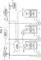
- Fig. 1 is an explanatory view for describing respective power generation equipment coupled to an electric power grid in the embodiment.
- Electric powers generated by electric power generators are supplied to an electric power grid 1.
- These electric power generators are installed in power generation equipment (station) built in respective regions (respective areas). For example, the electric power generators are installed in the thermal power generation equipment and the nuclear power generation equipment. Further, these electric power generators (GEN1, GEN2, and GEN3) are installed in the power generation equipment (station) built in one region (one area). For example, the electric power generators are installed in one piece of power generation equipment in a multiple (multi-shaft) way.
- the electric power generated by renewable energy power generation equipment 10 is supplied to the electric power grid 1.
- the renewable energy power generation equipment 10 is, for example, the photovoltaic power generation equipment and the wind power generation equipment.
- the respective power generation equipment is coupled to the electric power grid 1, where there is the mixed electric power generated by the renewable energy power generation equipment 10 and generated by the electric power generators (GEN1, GEN2, and GEN3) installed in the thermal power generating plant and the nuclear power generation equipment.
- the electric power generators GEN1, GEN2, and GEN3
- respective load terminal points (hereinafter, described as "power consumption area") 2 which consume the electric power supplied from the electric power grid 1 are coupled to the electric power grid 1.
- the electric power generators (GEN1, GEN2, and GEN3) respectively include AVRs (AVR: Automatic Voltage Regulator; hereinafter, described as "AVR”) (AVR11, AVR12, and AVR13).
- AVR Automatic Voltage Regulator
- the AVR11 (although AVR11 will be typically described, AVR12 and AVR13 have the same function) described in the embodiment is to automatically adjust the voltage of the electric power generated by the electric power generator GEN1 (although this description will be made by using the GEN1 corresponding to the AVR11, the same applies to the GEN2 corresponding to the AVR12 and the GEN3 corresponding to the AVR13) to a predetermined value.
- the AVR11 is to automatically adjust the voltage of the electric power supplied to the electric power grid 1.
- the AVR12 and the AVR13 are the same. In the embodiment, although the case of having three electric power generators and three AVRs is described, the number is not restricted to this.
- the AVR11 has a function of information and communication technology (ICT: Information and Communication Technology, hereinafter, described as “ICT”) and a function of automatic reactive power regulator (AQR: Automatic Q Regulator) (hereinafter, this function will be described as "Var regulation function").
- ICT Information and Communication Technology
- AQR Automatic Q Regulator
- the Var regulation function is a function of automatically adjusting the reactive power of the electric power generated by the electric power generator GEN1 to a predetermined value.
- the AVR12 and the AVR13 have the same function.
- a synchronous condenser 3 is coupled to the electric power grid 1.
- the synchronous condenser 3 is coupled to the electric power grid 1 in a no-load state, to adjust the reactive power of the electric power grid 1 in this embodiment.
- Reactive power control equipment 4 described in the embodiment is coupled to the power consumption area 2, the synchronous condenser 3, the AVR11, the AVR12, the AVR13, the renewable energy power generation equipment 10, and a central load dispatch center (hereinafter, described as "dispatch center") 5, to transmit and receive (input and output) the information of the reactive power to and from the above.
- a central load dispatch center hereinafter, described as "dispatch center"
- the dispatch center 5 monitors the used amount of the electric power in the power consumption area 2 and the electric generating power generated by the respective electric power generators (GEN1, GEN2, and GEN3) through the respective AVRs (11, 12, 13), and shares various types of information (effective electric power, frequency, voltage, and the like) including the information of the reactive power with the reactive power control equipment 4.
- the reactive power control equipment 4 in the embodiment is described using a cloud network (CLOUD NETWORK) capable of automatic analysis and high-speed calculation; however, it is not restricted to this as far as it can gather the information of the reactive power and automatically adjust the fluctuation of the reactive power set in the power consumption area 2.
- CLOUD NETWORK a cloud network
- the reactive power control equipment 4 receives the reactive power Q(1) from the AVR11, the reactive power Q(2) from the AVR12, and the reactive power Q(3) from the AVR13.
- Each of the reactive power Q(1), the reactive power Q(2), and the reactive power Q(3) is the reactive power of the electric power generated by each of the electric power generator GEN1, the electric power generator GEN2, and the electric power generator GEN3.
- the reactive power control equipment 4 receives the reactive power Q(r) of the electric power generated by the renewable energy power generation equipment 10 from the renewable energy power generation equipment 10.
- the reactive power control equipment 4 receives the reactive power Q(s) adjusted by the synchronous condenser 3 from the synchronous condenser 3.
- the reactive power control equipment 4 receives the reactive power Q(req) (request reactive power value) set in the power consumption area 2, or requested by the power consumption area 2, from the power consumption area 2.
- the reactive power control equipment 4 described in the embodiment calculates the reactive power Q(ideal) (1) as the setting value, for example, using the reactive power Q(req), the reactive power Q(1), the reactive power Q(s), and the reactive power Q(r) and outputs the reactive power Q(ideal) (1) to the AVR11.
- the above equipment outputs the reactive power Q(ideal)(2) to the AVR12 using the reactive power Q(2) and the like and the reactive power Q(ideal)(3) to the AVR13 using the reactive power Q(3) and the like.
- the reactive power control equipment 4 calculates the reactive power (reactive power Q(ideal)(1) and the reactive power Q(ideal)(s)) for the adjustment of the AVR11 and the synchronous condenser 3, and outputs the calculated reactive power (the reactive power Q(ideal) (1) and the reactive power Q(ideal) (s)) to the AVR11 and the synchronous condenser 3.
- the AVR11 and the synchronous condenser 3 control the reactive power (the reactive power Q(1) and the reactive power Q(s)) output by the AVR11 and the synchronous condenser 3, according to the input reactive power (the reactive power Q(ideal)(1) and the reactive power Q(ideal) (s)). The same ones apply to the AVR12 and the AVR13.
- the above equipment reports the reactive power Q(ideal) as the setting value to the power consumption area 2 (Report).
- the reactive power control equipment 4 described in the embodiment sequentially calculates the reactive power Q(ideal) in real time, for example, using the reactive power Q(1) (the reactive power Q(2) and the reactive power Q(3) are the same), the reactive power Q(s), and the reactive power Q(r), and controls the reactive power (Q(k) and Q(s)) to properly set the reactive power Q(req) requested by the power consumption area 2, in other words, the request reactive power value set in the power consumption area 2.
- the Q(k) is a general term of Q(1), Q(2), and Q(3).
- Fig. 2 is an explanatory view for describing a function of controlling the reactive power in the embodiment.
- the reactive power control equipment 4 described in the embodiment includes an input portion database 41 as the input portion, a calculation unit 42, and an output portion database 43 as the output portion.
- DB database
- the input portion DB 41 includes a consumption area input DB 25 for storing the reactive power Q(req) input from the power consumption area 2, a synchronous condenser input DB 35 for storing the reactive power Q(s) input from the synchronous condenser 3, an AVR11 input DB 21 for storing the reactive power Q(1) input from the AVR11, an AVR12 input DB 22 for storing the reactive power Q(2) input from the AVR12, an AVR13 input DB 23 for storing the reactive power Q(3) input from the AVR13, and a renewable energy power generation equipment input DB 15 for storing the reactive power Q(r) input from the renewable energy power generation equipment 10.
- the input portion DB 41 is an input portion for receiving the reactive power Q(req), the reactive power Q(s), the reactive power Q(1), the reactive power Q(2), the reactive power Q(3), and the reactive power Q(r), as the information of the reactive power.
- the calculation unit 42 calculates the reactive power Q(ideal)(1) as the setting value, for example, using the stored reactive power Q(req), reactive power Q(1), reactive power Q(s), and reactive power Q(r). Similarly, the calculation unit 42 calculates the reactive power Q(ideal)(2), using the reactive power Q(2) and the like, and the reactive power Q(ideal)(3), using the reactive power Q(3) and the like. Further, similarly, the calculation unit 42 calculates the reactive power Q(ideal)(s) as the setting value.
- the calculation unit 42 calculates the reactive power Q(ideal)(s) to be adjusted by the synchronous condenser 3 and the reactive power Q(ideal)(1, 2, 3) to be adjusted by the AVR(11, 12, 13), using the input reactive power information.
- the calculation unit 42 subtracts a total of, for example, the reactive power Q(1) adjusted by the AVR11 (the reactive power Q(2) adjusted by the AVR12 and the reactive power Q(3) adjusted by the AVR13 are the same), the reactive power Q(s) adjusted by the synchronous condenser 3, and the reactive power Q(r) of the electric power generated by the renewable energy power generation equipment 10, from the reactive power Q(req) set in the power consumption area 2, to calculate a deviation value.
- the calculation unit 42 compares this deviation value with predetermined reactive power (Q(gap) described later).
- the calculation unit 42 determines whether the loop continuous time is greater than the predetermined time or not.
- the calculation unit 42 slightly adjusts the predetermined reactive power (Q(gap) described later) to shorten the loop continuous time.
- the output portion DB 43 includes an AVR11 output DB 31, an AVR12 output DB 32, an AVR13 output DB 33, a consumption area output DB 26, and a synchronous condenser output DB 36.
- the output portion DB 43 stores the calculated reactive power Q(ideal)(1) in the AVR11 output DB 31, reactive power Q(ideal)(2) in the AVR12 output DB 32, reactive power Q(ideal)(3) in the AVR13 output DB 33, reactive power Q(ideal) in the consumption area output DB 26, and reactive power Q(ideal)(s) in the synchronous condenser output DB 36, and outputs the calculation results to the AVR11, the AVR12, the AVR13, and the synchronous condenser 3.
- the AVR11, the AVR12, the AVR13, and the synchronous condenser 3 control the reactive power (the reactive power Q(1), the reactive power Q(2), the reactive power Q(3), and the reactive power Q(s)) output by the AVR11, the AVR12, the AVR13, and the synchronous condenser 3, based on the output calculation results (the reactive power Q(ideal)(1), the reactive power Q(ideal)(2), the reactive power Q(ideal)(3), and the reactive power Q(ideal)(s)).
- the output portion DB 43 is an output portion of outputting the reactive power calculated by the calculation unit 42 (the reactive power Q(ideal)(1), the reactive power Q(ideal)(2), the reactive power Q(ideal)(3), and the reactive power Q(ideal)(s)) to the AVR11, the AVR12, the AVR13, and the synchronous condenser 3.
- the output portion DB 43 reports the reactive power Q(ideal) as the setting value to the power consumption area 2 (Report).
- the reactive power Q(req) even in the electric power grid 1 including a mixture of the electric power generated by the renewable energy power generation equipment 10 and the electric power generated by the electric power generators (GEN1, GEN2, and GEN3) installed in the thermal power generating plant and the nuclear power generation equipment, it is possible to stably control the reactive power Q(req) to satisfy the reactive power Q(req) requested by the power consumption area 2, in other words, the request reactive power value set in power consumption area 2, for example, using the reactive power Q(1) (the reactive power Q(2) and the reactive power Q(3) are the same), the reactive power Q(s), and the reactive power Q(r), by sequentially calculating the reactive power Q(ideal) in real time.
- a reactive power control method described in the embodiment includes a process of inputting the reactive power Q(1) (the reactive power Q(2) and the reactive power Q(3) are the same), the reactive power Q(s), the reactive power Q(r), and the reactive power Q(req) as the reactive power information, a process of calculating the reactive power (the reactive power Q(ideal)(1), the reactive power Q(ideal)(2), the reactive power Q(ideal)(3), and the reactive power Q(ideal)(s)) adjusted by the AVR(11, 12, 13) and the synchronous condenser 3, using the input reactive power information, and a process of outputting the calculated reactive power (the reactive power Q(ideal)(1), the reactive power Q(ideal)(2), the reactive power Q(ideal)(3), and the reactive power Q(ideal)(s)) to the AVR(11, 12, 13) and the synchronous condenser 3.
- the reactive power control equipment 4 has an ICT function, which enables centralized supervision and centralized control. Further, the above has a function of sequentially controlling the reactive power and a function of centralizing the reactive power information in real time. Even when the electric power grid 1 contains the unsteadily-fluctuating renewable energy power generation equipment 10, it is possible to sequentially solve the unpredictable behavior of the reactive power in the power consumption area 2 and properly control the reactive power in real time.
- the AVR described in the embodiment has the ICT function and a Var regulation function, which enables data communication and data cooperation, and further, can sequentially adjust the reactive power in real time.
- the AVR has a function of automatically and sequentially receiving (inputting) the reactive power calculated by the reactive power control equipment 4, in real time, as a feedback instruction, until the reactive power in the power consumption area 2 becomes proper.
- the Var regulation function is centralized in the AVR, hence saving space in the installation area at the site can be expected.
- the embodiment enables the centralized supervision and the centralized control of the reactive power of the power generation equipment affecting the power consumption area 2, according to the reactive power control equipment 4.
- the unsteadily-fluctuating renewable energy power generation equipment 10, the AVR, and the synchronous condenser 3 are cooperatively operated through the reactive power control equipment 4, so that the same equipment 4 receives (collects, inputs) the reactive power information in real time from the renewable energy power generation equipment 10, the AVR, and the synchronous condenser 3.
- the reactive power is sequentially controlled in the AVR and the synchronous condenser 3.
- Fig. 3 is an explanatory view for describing a flow chart for controlling the reactive power in the embodiment.
- the reactive power control equipment 4 receives (collects and inputs) the reactive power Q automatically and continuously (sequentially and in real time) in the input portion, calculates the above in the calculation unit 42, and transmits (outputs) the calculation result in the output portion.
- the reactive power control method includes a process of inputting (collecting and receiving) the reactive power Q automatically and continuously (sequentially and in real time) in the input portion, a process of calculating the reactive power Q in the calculation unit 42, and a process of outputting (transmitting) the calculation result in the output portion.
- the calculation unit 42 performs the following processing (calculating process).
- the reactive power Q(1) is input from the AVR11
- the reactive power Q(2) is input from the AVR12
- the reactive power Q(3) is input from the AVR13.
- the reactive power Q from the AVR(k) with the loop number i is represented as reactive power Q(k, i).
- the reactive power Q from the AVR11 of the loop number (first) is represented as the reactive power Q(11, 1).
- the reactive power Q(r) is input from the renewable energy power generation equipment 10.
- the reactive power Q from the renewable energy power generation equipment 10 with the loop number i is represented as the reactive power Q(r, i).
- the reactive power Q(s) is input from the synchronous condenser 3.
- the reactive power Q from the synchronous condenser 3 with the loop number i is represented as the reactive power Q(s, i).
- the reactive power Q(req) (request reactive power value) is input from the power consumption area 2.
- a process of monitoring the current value of the reactive power Q and setting the setting value (operation pattern) is performed (103).
- the above is performed on the reactive power Q(k, i) and the reactive power Q(s, i) .
- the reactive power Q(k, i) and the reactive power Q(s, i) are set as the reactive power Q(ideal)(k, i) and the reactive power Q(ideal)(s, i) calculated in the reactive power control equipment 4.
- the reactive power Q(k, 0) and the reactive power Q(s, 0) are set as the initial value.
- the reactive power Q(k, i) as the current value can be monitored sequentially and in real time, and the reactive power Q(ideal)(k, i) and the reactive power Q(ideal)(s, i) as the setting value are set after examining the fluctuation factor comprehensively.
- the fluctuation factor includes, for example, fluctuation of the electric generating power in the renewable energy power generation equipment 10 with the form of the electric power generation (photovoltaic power generation and wind power generation) and regionality taken into consideration, a change of the operation pattern in the power consumption area 2, and stability of the electric power grid 1 depending on the running number and the installation number of the electric power generators (GEN1, GEN2, and GEN3) and the synchronous condenser 3.
- a deviation value of the reactive power Q(req) (request reactive power value) from the total of the reactive power Q(k, i), the reactive power Q(s, i), and the reactive power Q(r, i) is within a predetermined values (reactive power Q(gap)) (104).
- the reactive power Q(gap) is a desired deviation of the reactive power and the initial setting value of the reactive power Q(gap) is set based on the major conditional plan described later (accumulated data in the past). This reactive power Q(gap) (reactive power desired deviation) can be changed between daytime and nighttime.
- the reactive power of adding Q(k, i), Q(s, i), and Q(r, i) is subtracted from the Q(req) to calculate a deviation value.
- this deviation value is compared with the Q(gap) (predetermined reactive power deviation).
- the reactive power Q(gap) can be adjusted in the calculation unit 42 of the reactive power control equipment 4.
- the relational expression (1) when the left side is Q(gap) and more, it is determined whether or not the loop continuous time is a predetermined time and more. In the embodiment, it is determined, for example, whether or not the loop continuous time is 0.1 second or more (105).
- the deviation value is Q(gap) (the predetermined reactive power) and more, it is determined whether or not the loop continuous time is the predetermined time (0.1 second in the embodiment) and more.
- the above determination is performed because the electric power becomes instable especially when the renewable energy power generation equipment 10 is coupled to the electric power grid 1; for the electric power generated by the renewable energy power generation equipment 10 is greatly affected by the environment (for example weather etc.) and the fluctuation of the electric power becomes large.
- the reactive power Q(ideal)(k, i) and the reactive power Q(ideal)(s, i) as the setting value are reconsidered (106).
- they are reconsidered also by comprehensively re-examining the fluctuation factor.
- the Q(gap) is slightly adjusted to shorten the loop continuous time (108).
- the Q(gap) predetermined reactive power
- the above slight adjustment is performed because the electric power becomes instable especially when the renewable energy power generation equipment 10 is coupled to the electric power grid 1; for the electric power generated by the renewable energy power generation equipment 10 is greatly affected by the environment (for example weather etc.) and the fluctuation of the electric power becomes large.
- the slight adjustment is to modify the initial setting value of the Q(gap), regardless of the size of the modified value.
- Fig. 4 is an explanatory view for describing the slight adjustment of a desired deviation of the reactive power according to the embodiment.
- Fig. 4 shows a relation, for example, between the reactive power (Q) and the time (t), imaging that the reactive power (here, this is described as (reactive power Q)) on the left side of the relational expression (1) converges on the Q(ideal).
- the (reactive power Q) does not converge in the range of 2Q(gap) with the Q(ideal) set as the center at the time t1.
- the initial setting value (initial value) is slightly adjusted to Q'(gap)
- the (reactive power Q) converges in the range of 2Q'(gap) with the Q(ideal) set as the center at the time t1.
- the setting time can be set to be shorter as the determination becomes severer and to be longer as the determination becomes looser.
- the photovoltaic power generation and the wind power generation as the typical renewable energy power generation equipment 10 respectively supply the reactive power Qs(r, i) (photovoltaic) and the reactive power Qw(r, i) (wind power) to the grid side
- the reactive power Qs(r, i) (photovoltaic) and the reactive power Qw(r, i) (wind power) are different in the electric generating power under a predetermined condition, and according to this, the Q(gap) to be preset (initially set) has to be adjusted.
- the main conditional plan to affect the reactive power Qs(r, i) includes time (hh hour mm minute), date (mm month dd day), weather (clear (cloud cover 0 to 10%), fair (cloud cover 20 to 80%),cloudy (cloud cover 90 to 100%), rain, snow, fog, and the like), place (regional difference in latitude and longitude), equipment specifications of the photovoltaic power generation (panel area, power generation efficiency, rated solar insolation, etc.), and the like.
- coefficients for correction according to the weather are classified, to adjust the gap through multiplication by a predetermined rate.
- the adjustment coefficient plan the latest weather information is obtained from a database of the Metrological Agency and the like in real time. For example, as the correction by (1) cloud cover, some amount ⁇ (100 - cloud cover)% and as the correction by (2) rain, snow, and fog, some amount ⁇ 50 (typical)% may be considered.
- the main conditional plan to affect the reactive power Qw(r, i) (in the power generation equipment, the actually blowing wind affects the revolution per minute (RPM) of a wind turbine of the electric power generator) includes place (regional difference in latitude and longitude), date (mm month dd day) (generally, wind speed tends to be higher in winter and lower in summer), ground level (generally, wind speed tends to be higher according as the altitude gets higher and lower according as the altitude gets lower), equipment specifications of the wind power generation (installation number, rated wind speed, power generation efficiency, yaw control of windmill, presence or absence of the operating blade, etc.), and the like.
- place regional difference in latitude and longitude
- date mm month dd day
- ground level generally, wind speed tends to be higher according as the altitude gets higher and lower according as the altitude gets lower
- equipment specifications of the wind power generation installation number, rated wind speed, power generation efficiency, yaw control of windmill, presence or absence of the operating blade,
- coefficients for correction according to the oscillation factor are classified, hence to adjust the gap through multiplication by a predetermined average wind speed. For example, as the correction by (1) date (seasons), some amount ⁇ 1.0 (spring/autumn), some amount ⁇ 0.8 (summer), some amount ⁇ 1.2 (winter) (typical) and as the correction by (2) yaw control of windmill and presence or absence of operating blade, some amount ⁇ cos ⁇ ( ⁇ : angle made by wind speed vector and windmill rotation axis) may be considered.
- a DB about the electric generating capacity of the renewable energy for the date and time in the past is provided, and predetermined reactive power is set based on the electric generating capacity stored in the above DB. Further, the predetermined reactive power is adjusted according to the adjustment coefficient (adjustment coefficient plan) based on the weather information in real time.
- this method is effective in the sever determination like the relation of (1) in the vicinity of the boundary range of the Q(gap).
Landscapes
- Engineering & Computer Science (AREA)
- Power Engineering (AREA)
- Physics & Mathematics (AREA)
- General Physics & Mathematics (AREA)
- Electromagnetism (AREA)
- Radar, Positioning & Navigation (AREA)
- Automation & Control Theory (AREA)
- Supply And Distribution Of Alternating Current (AREA)
- Control Of Eletrric Generators (AREA)
Abstract
Description
- The invention relates to reactive power control equipment and a reactive power control method. Background
- These days, with increasing environmental consciousness, renewable energy power generation equipment is increasing at a high speed. The ratio of the power through the renewable energy electric power generation in the whole generated electric power is increasing year by year. The renewable energy electric power generation, however, is unstable in the power supply; for example, photovoltaic power generation is affected by bad weather, and wind power generation is affected by wind speed. Therefore, in the present circumstances, the power generated by the renewable energy power generation equipment is difficult to be completely replaced with the power generated by the base load power generation equipment such as thermal power generation and nuclear power generation.
- Accordingly, the power supplied to an electric power grid is a combination of the power generated by the renewable energy power generation equipment and the power generated by the thermal power plant and the nuclear power equipment.
- The ratio of the power generated by the renewable energy power generation equipment tends to increase. Since one electric power grid includes the combined power generated by the renewable energy power generation equipment and generated by the thermal power plant and the nuclear power equipment, the voltage and frequency of the electric power shows unpredictable behavior in each load terminal point (power consumption area) coupled to the electric power grid, and it is difficult to optimally control the voltage and frequency in each load terminal point (power consumption area).
- As the background art of this technical field, there is Japanese Unexamined Patent Application Publication No.
2016-208654 - Japanese Unexamined Patent Application Publication No.
2016-208654 - The invention provides reactive power control equipment and a reactive power control method of controlling the reactive power adjusted by a synchronous condenser coupled to the electric power grid and the reactive power of the electric power supplied to the electric power grid, to optimally control the reactive power in each load terminal point (power consumption area), considering the instability of the electric power supplied from the renewable energy power generation equipment.
- The reactive power control equipment described in the invention includes an input portion that inputs the information of reactive power including the reactive power adjusted by an automatic voltage regulator of automatically adjusting a voltage of electric power generated by an electric power generator and supplied to an electric power grid, reactive power adjusted by a synchronous condenser coupled to the electric power grid, the reactive power of electric power generated by the renewable energy power generation equipment, and reactive power set in each load terminal point (consumer area) of consuming the electric power; a calculation unit that calculates each setting value of the reactive power adjusted by the synchronous condenser and the automatic voltage regulator, using the information of the reactive power input in the input portion; and/or an output portion that outputs the setting values of the reactive power calculated by the calculation unit respectively to the synchronous condensers and the automatic voltage regulators.
- Further, the reactive power control method described in the invention includes the following steps of: inputting information of the reactive power including reactive power adjusted by an automatic voltage regulator of automatically adjusting a voltage of electric power generated by an electric power generator and supplied to the electric power grid, reactive power adjusted by a synchronous condenser coupled to the electric power grid, reactive power of electric power generated by the renewable energy power generation equipment, and reactive power set in each load terminal point (power consumption area) of consuming the electric power; calculating each setting value of the reactive power adjusted by the synchronous condenser and the automatic voltage regulator, using the input reactive power information; and/or outputting the calculated setting values of the reactive power respectively to the synchronous condensers and the automatic voltage regulators.
- The invention is to provide the reactive power control equipment and the reactive power control method of controlling the reactive power adjusted by the synchronous condenser coupled to the electric power grid and the reactive power of the electric power supplied to the electric power grid, to optimally control the reactive power in each load terminal point (power consumption area), considering the instability of the electric power supplied from the renewable energy power generation equipment.
- Other objects, structures, and effects than the above will be cleared according to the description of the following embodiment.
-
-
Fig. 1 is an explanatory view for describing respective power generation equipment coupled to an electric power grid according to the embodiment; -
Fig. 2 is an explanatory view for describing a function of controlling the reactive power according to the embodiment; -
Fig. 3 is an explanatory view for describing a flow chart of controlling the reactive power according to the embodiment; and -
Fig. 4 is an explanatory view for describing slight adjustment of desired deviation of the reactive power according to the embodiment. - Hereinafter, a preferred embodiment will be described with reference to the drawings. The same reference numerals are attached to the same components and the description is saved when there is an overlapping description.
-
Fig. 1 is an explanatory view for describing respective power generation equipment coupled to an electric power grid in the embodiment. - Electric powers generated by electric power generators (GEN1, GEN2, and GEN3) are supplied to an
electric power grid 1. These electric power generators (GEN1, GEN2, and GEN3) are installed in power generation equipment (station) built in respective regions (respective areas). For example, the electric power generators are installed in the thermal power generation equipment and the nuclear power generation equipment. Further, these electric power generators (GEN1, GEN2, and GEN3) are installed in the power generation equipment (station) built in one region (one area). For example, the electric power generators are installed in one piece of power generation equipment in a multiple (multi-shaft) way. - The electric power generated by renewable energy
power generation equipment 10 is supplied to theelectric power grid 1. The renewable energypower generation equipment 10 is, for example, the photovoltaic power generation equipment and the wind power generation equipment. - As mentioned above, in the embodiment, the respective power generation equipment is coupled to the
electric power grid 1, where there is the mixed electric power generated by the renewable energypower generation equipment 10 and generated by the electric power generators (GEN1, GEN2, and GEN3) installed in the thermal power generating plant and the nuclear power generation equipment. - Further, respective load terminal points (hereinafter, described as "power consumption area") 2 which consume the electric power supplied from the
electric power grid 1 are coupled to theelectric power grid 1. - As the result, particularly because of instability of the electric power generated by the renewable energy
power generation equipment 10, there is a possibility that a request reactive power value to be requested by thepower consumption area 2 cannot be set properly, as for the electric power supplied from theelectric power grid 1 including a mixture of the electric power generated by the renewable energypower generation equipment 10 and the electric power generated by the electric power generators (GEN1, GEN2, and GEN3) installed in the thermal power generating plants and the nuclear power generation equipment. - The electric power generators (GEN1, GEN2, and GEN3) respectively include AVRs (AVR: Automatic Voltage Regulator; hereinafter, described as "AVR") (AVR11, AVR12, and AVR13).
- The AVR11 (although AVR11 will be typically described, AVR12 and AVR13 have the same function) described in the embodiment is to automatically adjust the voltage of the electric power generated by the electric power generator GEN1 (although this description will be made by using the GEN1 corresponding to the AVR11, the same applies to the GEN2 corresponding to the AVR12 and the GEN3 corresponding to the AVR13) to a predetermined value. In short, the AVR11 is to automatically adjust the voltage of the electric power supplied to the
electric power grid 1. The AVR12 and the AVR13 are the same. In the embodiment, although the case of having three electric power generators and three AVRs is described, the number is not restricted to this. - The AVR11 has a function of information and communication technology (ICT: Information and Communication Technology, hereinafter, described as "ICT") and a function of automatic reactive power regulator (AQR: Automatic Q Regulator) (hereinafter, this function will be described as "Var regulation function"). Here, the Var regulation function is a function of automatically adjusting the reactive power of the electric power generated by the electric power generator GEN1 to a predetermined value. The AVR12 and the AVR13 have the same function.
- Further, a
synchronous condenser 3 is coupled to theelectric power grid 1. Here, thesynchronous condenser 3 is coupled to theelectric power grid 1 in a no-load state, to adjust the reactive power of theelectric power grid 1 in this embodiment. - Reactive
power control equipment 4 described in the embodiment is coupled to thepower consumption area 2, thesynchronous condenser 3, the AVR11, the AVR12, the AVR13, the renewable energypower generation equipment 10, and a central load dispatch center (hereinafter, described as "dispatch center") 5, to transmit and receive (input and output) the information of the reactive power to and from the above. - The dispatch center 5 monitors the used amount of the electric power in the
power consumption area 2 and the electric generating power generated by the respective electric power generators (GEN1, GEN2, and GEN3) through the respective AVRs (11, 12, 13), and shares various types of information (effective electric power, frequency, voltage, and the like) including the information of the reactive power with the reactivepower control equipment 4. - The reactive
power control equipment 4 in the embodiment is described using a cloud network (CLOUD NETWORK) capable of automatic analysis and high-speed calculation; however, it is not restricted to this as far as it can gather the information of the reactive power and automatically adjust the fluctuation of the reactive power set in thepower consumption area 2. - The reactive
power control equipment 4 receives the reactive power Q(1) from the AVR11, the reactive power Q(2) from the AVR12, and the reactive power Q(3) from the AVR13. Each of the reactive power Q(1), the reactive power Q(2), and the reactive power Q(3) is the reactive power of the electric power generated by each of the electric power generator GEN1, the electric power generator GEN2, and the electric power generator GEN3. - The reactive
power control equipment 4 receives the reactive power Q(r) of the electric power generated by the renewable energypower generation equipment 10 from the renewable energypower generation equipment 10. - The reactive
power control equipment 4 receives the reactive power Q(s) adjusted by thesynchronous condenser 3 from thesynchronous condenser 3. - The reactive
power control equipment 4 receives the reactive power Q(req) (request reactive power value) set in thepower consumption area 2, or requested by thepower consumption area 2, from thepower consumption area 2. - The reactive
power control equipment 4 described in the embodiment calculates the reactive power Q(ideal) (1) as the setting value, for example, using the reactive power Q(req), the reactive power Q(1), the reactive power Q(s), and the reactive power Q(r) and outputs the reactive power Q(ideal) (1) to the AVR11. Similarly, the above equipment outputs the reactive power Q(ideal)(2) to the AVR12 using the reactive power Q(2) and the like and the reactive power Q(ideal)(3) to the AVR13 using the reactive power Q(3) and the like. - Further, the above outputs the reactive power Q(ideal)(s) as the setting value to the
synchronous condenser 3. - Using the input reactive power information, the reactive
power control equipment 4 calculates the reactive power (reactive power Q(ideal)(1) and the reactive power Q(ideal)(s)) for the adjustment of the AVR11 and thesynchronous condenser 3, and outputs the calculated reactive power (the reactive power Q(ideal) (1) and the reactive power Q(ideal) (s)) to the AVR11 and thesynchronous condenser 3. The AVR11 and thesynchronous condenser 3 control the reactive power (the reactive power Q(1) and the reactive power Q(s)) output by the AVR11 and thesynchronous condenser 3, according to the input reactive power (the reactive power Q(ideal)(1) and the reactive power Q(ideal) (s)). The same ones apply to the AVR12 and the AVR13. - Further, the above equipment reports the reactive power Q(ideal) as the setting value to the power consumption area 2 (Report).
- Even in the
electric power grid 1 including a mixture of the electric power generated by the renewable energypower generation equipment 10 and the electric power generated by the electric power generators (GEN1, GEN2, and GEN3) installed in the thermal power generating plant and the nuclear power generation equipment, the reactivepower control equipment 4 described in the embodiment sequentially calculates the reactive power Q(ideal) in real time, for example, using the reactive power Q(1) (the reactive power Q(2) and the reactive power Q(3) are the same), the reactive power Q(s), and the reactive power Q(r), and controls the reactive power (Q(k) and Q(s)) to properly set the reactive power Q(req) requested by thepower consumption area 2, in other words, the request reactive power value set in thepower consumption area 2. Here, the Q(k) is a general term of Q(1), Q(2), and Q(3). -
Fig. 2 is an explanatory view for describing a function of controlling the reactive power in the embodiment. - The reactive
power control equipment 4 described in the embodiment includes aninput portion database 41 as the input portion, acalculation unit 42, and anoutput portion database 43 as the output portion. Hereinafter, the database will be described as "DB". - The
input portion DB 41 includes a consumptionarea input DB 25 for storing the reactive power Q(req) input from thepower consumption area 2, a synchronouscondenser input DB 35 for storing the reactive power Q(s) input from thesynchronous condenser 3, anAVR11 input DB 21 for storing the reactive power Q(1) input from the AVR11, anAVR12 input DB 22 for storing the reactive power Q(2) input from the AVR12, anAVR13 input DB 23 for storing the reactive power Q(3) input from the AVR13, and a renewable energy power generationequipment input DB 15 for storing the reactive power Q(r) input from the renewable energypower generation equipment 10. - In other words, the
input portion DB 41 is an input portion for receiving the reactive power Q(req), the reactive power Q(s), the reactive power Q(1), the reactive power Q(2), the reactive power Q(3), and the reactive power Q(r), as the information of the reactive power. - The
calculation unit 42 calculates the reactive power Q(ideal)(1) as the setting value, for example, using the stored reactive power Q(req), reactive power Q(1), reactive power Q(s), and reactive power Q(r). Similarly, thecalculation unit 42 calculates the reactive power Q(ideal)(2), using the reactive power Q(2) and the like, and the reactive power Q(ideal)(3), using the reactive power Q(3) and the like. Further, similarly, thecalculation unit 42 calculates the reactive power Q(ideal)(s) as the setting value. - In short, the
calculation unit 42 calculates the reactive power Q(ideal)(s) to be adjusted by thesynchronous condenser 3 and the reactive power Q(ideal)(1, 2, 3) to be adjusted by the AVR(11, 12, 13), using the input reactive power information. - The
calculation unit 42 subtracts a total of, for example, the reactive power Q(1) adjusted by the AVR11 (the reactive power Q(2) adjusted by the AVR12 and the reactive power Q(3) adjusted by the AVR13 are the same), the reactive power Q(s) adjusted by thesynchronous condenser 3, and the reactive power Q(r) of the electric power generated by the renewable energypower generation equipment 10, from the reactive power Q(req) set in thepower consumption area 2, to calculate a deviation value. - The
calculation unit 42 compares this deviation value with predetermined reactive power (Q(gap) described later). - When the deviation value is the predetermined reactive power (Q(gap) described later) and more, the
calculation unit 42 determines whether the loop continuous time is greater than the predetermined time or not. - When the loop duration time reaches the predetermined time and more, the
calculation unit 42 slightly adjusts the predetermined reactive power (Q(gap) described later) to shorten the loop continuous time. - The
output portion DB 43 includes anAVR11 output DB 31, anAVR12 output DB 32, anAVR13 output DB 33, a consumptionarea output DB 26, and a synchronouscondenser output DB 36. Theoutput portion DB 43 stores the calculated reactive power Q(ideal)(1) in theAVR11 output DB 31, reactive power Q(ideal)(2) in theAVR12 output DB 32, reactive power Q(ideal)(3) in theAVR13 output DB 33, reactive power Q(ideal) in the consumptionarea output DB 26, and reactive power Q(ideal)(s) in the synchronouscondenser output DB 36, and outputs the calculation results to the AVR11, the AVR12, the AVR13, and thesynchronous condenser 3. - The AVR11, the AVR12, the AVR13, and the
synchronous condenser 3 control the reactive power (the reactive power Q(1), the reactive power Q(2), the reactive power Q(3), and the reactive power Q(s)) output by the AVR11, the AVR12, the AVR13, and thesynchronous condenser 3, based on the output calculation results (the reactive power Q(ideal)(1), the reactive power Q(ideal)(2), the reactive power Q(ideal)(3), and the reactive power Q(ideal)(s)). - In short, the
output portion DB 43 is an output portion of outputting the reactive power calculated by the calculation unit 42 (the reactive power Q(ideal)(1), the reactive power Q(ideal)(2), the reactive power Q(ideal)(3), and the reactive power Q(ideal)(s)) to the AVR11, the AVR12, the AVR13, and thesynchronous condenser 3. - Further, the
output portion DB 43 reports the reactive power Q(ideal) as the setting value to the power consumption area 2 (Report). - According to this, even in the
electric power grid 1 including a mixture of the electric power generated by the renewable energypower generation equipment 10 and the electric power generated by the electric power generators (GEN1, GEN2, and GEN3) installed in the thermal power generating plant and the nuclear power generation equipment, it is possible to stably control the reactive power Q(req) to satisfy the reactive power Q(req) requested by thepower consumption area 2, in other words, the request reactive power value set inpower consumption area 2, for example, using the reactive power Q(1) (the reactive power Q(2) and the reactive power Q(3) are the same), the reactive power Q(s), and the reactive power Q(r), by sequentially calculating the reactive power Q(ideal) in real time. - Then, a reactive power control method described in the embodiment includes a process of inputting the reactive power Q(1) (the reactive power Q(2) and the reactive power Q(3) are the same), the reactive power Q(s), the reactive power Q(r), and the reactive power Q(req) as the reactive power information, a process of calculating the reactive power (the reactive power Q(ideal)(1), the reactive power Q(ideal)(2), the reactive power Q(ideal)(3), and the reactive power Q(ideal)(s)) adjusted by the AVR(11, 12, 13) and the
synchronous condenser 3, using the input reactive power information, and a process of outputting the calculated reactive power (the reactive power Q(ideal)(1), the reactive power Q(ideal)(2), the reactive power Q(ideal)(3), and the reactive power Q(ideal)(s)) to the AVR(11, 12, 13) and thesynchronous condenser 3. - The reactive
power control equipment 4 has an ICT function, which enables centralized supervision and centralized control. Further, the above has a function of sequentially controlling the reactive power and a function of centralizing the reactive power information in real time. Even when theelectric power grid 1 contains the unsteadily-fluctuating renewable energypower generation equipment 10, it is possible to sequentially solve the unpredictable behavior of the reactive power in thepower consumption area 2 and properly control the reactive power in real time. - Further, the AVR described in the embodiment has the ICT function and a Var regulation function, which enables data communication and data cooperation, and further, can sequentially adjust the reactive power in real time. Especially, the AVR has a function of automatically and sequentially receiving (inputting) the reactive power calculated by the reactive
power control equipment 4, in real time, as a feedback instruction, until the reactive power in thepower consumption area 2 becomes proper. Further, the Var regulation function is centralized in the AVR, hence saving space in the installation area at the site can be expected. - The embodiment enables the centralized supervision and the centralized control of the reactive power of the power generation equipment affecting the
power consumption area 2, according to the reactivepower control equipment 4. The unsteadily-fluctuating renewable energypower generation equipment 10, the AVR, and thesynchronous condenser 3 are cooperatively operated through the reactivepower control equipment 4, so that thesame equipment 4 receives (collects, inputs) the reactive power information in real time from the renewable energypower generation equipment 10, the AVR, and thesynchronous condenser 3. The reactive power is sequentially controlled in the AVR and thesynchronous condenser 3. - Even in the
electric power grid 1 increasing more and more in the ratio of the electric generating capacity of the renewable energypower generation equipment 10, it is possible to realize stable control of the reactive power Q(req) (request reactive power value) requested by thepower consumption area 2 or set in thepower consumption area 2. -
Fig. 3 is an explanatory view for describing a flow chart for controlling the reactive power in the embodiment. - The reactive
power control equipment 4 receives (collects and inputs) the reactive power Q automatically and continuously (sequentially and in real time) in the input portion, calculates the above in thecalculation unit 42, and transmits (outputs) the calculation result in the output portion. - The reactive power control method includes a process of inputting (collecting and receiving) the reactive power Q automatically and continuously (sequentially and in real time) in the input portion, a process of calculating the reactive power Q in the
calculation unit 42, and a process of outputting (transmitting) the calculation result in the output portion. - Particularly, the
calculation unit 42 performs the following processing (calculating process). - At first, the processing starts with the repetition number (i) of calculation loop, or the loop number i = 0 (101) .
- Then, various types of reactive power Q are input (102) .
- Specifically, the reactive power Q(1) is input from the AVR11, the reactive power Q(2) is input from the AVR12, and the reactive power Q(3) is input from the AVR13. Here, the reactive power Q from the AVR(k) with the loop number i is represented as reactive power Q(k, i). For example, the reactive power Q from the AVR11 of the loop number (first) is represented as the reactive power Q(11, 1).
- The reactive power Q(r) is input from the renewable energy
power generation equipment 10. Here, the reactive power Q from the renewable energypower generation equipment 10 with the loop number i is represented as the reactive power Q(r, i). - The reactive power Q(s) is input from the
synchronous condenser 3. Here, the reactive power Q from thesynchronous condenser 3 with the loop number i is represented as the reactive power Q(s, i). - The reactive power Q(req) (request reactive power value) is input from the
power consumption area 2. - Next, a process of monitoring the current value of the reactive power Q and setting the setting value (operation pattern) is performed (103). Particularly, in the embodiment, the above is performed on the reactive power Q(k, i) and the reactive power Q(s, i) . In other words, the reactive power Q(k, i) and the reactive power Q(s, i) are set as the reactive power Q(ideal)(k, i) and the reactive power Q(ideal)(s, i) calculated in the reactive
power control equipment 4. In the case of the loop number i = 0, the reactive power Q(k, 0) and the reactive power Q(s, 0) are set as the initial value. - The reactive power Q(k, i) as the current value can be monitored sequentially and in real time, and the reactive power Q(ideal)(k, i) and the reactive power Q(ideal)(s, i) as the setting value are set after examining the fluctuation factor comprehensively. The fluctuation factor includes, for example, fluctuation of the electric generating power in the renewable energy
power generation equipment 10 with the form of the electric power generation (photovoltaic power generation and wind power generation) and regionality taken into consideration, a change of the operation pattern in thepower consumption area 2, and stability of theelectric power grid 1 depending on the running number and the installation number of the electric power generators (GEN1, GEN2, and GEN3) and thesynchronous condenser 3. - Next, it is determined whether or not a deviation value of the reactive power Q(req) (request reactive power value) from the total of the reactive power Q(k, i), the reactive power Q(s, i), and the reactive power Q(r, i) is within a predetermined values (reactive power Q(gap)) (104). The reactive power Q(gap) is a desired deviation of the reactive power and the initial setting value of the reactive power Q(gap) is set based on the major conditional plan described later (accumulated data in the past). This reactive power Q(gap) (reactive power desired deviation) can be changed between daytime and nighttime.
- Specifically, the relation of (1) If {Q(req) - [Q(k, i) + Q(s, i) + Q(r, i)] < Q(gap)} is determined. When there are plural Q(k, i) + Q(s, i) + Q(r, i), these are added.
- In the calculating process, the reactive power of adding Q(k, i), Q(s, i), and Q(r, i) is subtracted from the Q(req) to calculate a deviation value.
- Further, in the calculating process, this deviation value is compared with the Q(gap) (predetermined reactive power deviation).
- When the relational expression (1) is satisfied, in other words, when the left side is less than the Q(gap), the reactive power Q is determined to be proper (no Alarm light on).
- When the relational expression (1) is not satisfied, in other words, when the left side is Q(gap) and more, the reactive power Q is determined to be improper (Alarm light on) .
- Here, the reactive power Q(gap) can be adjusted in the
calculation unit 42 of the reactivepower control equipment 4. - Next, when the relational expression (1) is satisfied, in other words, when the left side is less than Q(gap), the reactive power Q is kept (110).
- Then, the loop number i is increased by "1" and the current value and the setting value of the reactive power Q are updated (111).
- On the other hand, when the relational expression (1) is not satisfied, in other words, when the left side is Q(gap) and more, it is determined whether or not the loop continuous time is a predetermined time and more. In the embodiment, it is determined, for example, whether or not the loop continuous time is 0.1 second or more (105).
- In other words, in the calculating process, when the deviation value is Q(gap) (the predetermined reactive power) and more, it is determined whether or not the loop continuous time is the predetermined time (0.1 second in the embodiment) and more.
- The above determination is performed because the electric power becomes instable especially when the renewable energy
power generation equipment 10 is coupled to theelectric power grid 1; for the electric power generated by the renewable energypower generation equipment 10 is greatly affected by the environment (for example weather etc.) and the fluctuation of the electric power becomes large. - When the loop continuous time is less than 0.1 second, the reactive power Q(ideal)(k, i) and the reactive power Q(ideal)(s, i) as the setting value are reconsidered (106). Here, they are reconsidered also by comprehensively re-examining the fluctuation factor.
- Then, the loop number i is increased by "1", to update the current value and the setting value of the reactive power Q (107).
- On the other hand, when the loop continuous time is 0.1 second or more, the Q(gap) is slightly adjusted to shorten the loop continuous time (108).
- In the calculating process, when the loop continuous time is the predetermined time (0.1 second in the embodiment) or more, the Q(gap) (predetermined reactive power) is slightly adjusted to shorten the loop continuous time.
- The above slight adjustment is performed because the electric power becomes instable especially when the renewable energy
power generation equipment 10 is coupled to theelectric power grid 1; for the electric power generated by the renewable energypower generation equipment 10 is greatly affected by the environment (for example weather etc.) and the fluctuation of the electric power becomes large. Here, the slight adjustment is to modify the initial setting value of the Q(gap), regardless of the size of the modified value. - Then, the Q(gap) is replaced with the slightly-adjusted Q'(gap) (Q(gap) = Q'(gap)) and again the determination of the relational expression (1) is performed (109).
-
Fig. 4 is an explanatory view for describing the slight adjustment of a desired deviation of the reactive power according to the embodiment. - Here, the slight adjustment of the above desired deviation is described using
Fig. 4. Fig. 4 shows a relation, for example, between the reactive power (Q) and the time (t), imaging that the reactive power (here, this is described as (reactive power Q)) on the left side of the relational expression (1) converges on the Q(ideal). - When the initial setting value is the Q(gap), the (reactive power Q) does not converge in the range of 2Q(gap) with the Q(ideal) set as the center at the time t1. On the other hand, when the initial setting value (initial value) is slightly adjusted to Q'(gap), the (reactive power Q) converges in the range of 2Q'(gap) with the Q(ideal) set as the center at the time t1.
- As mentioned above, by slightly adjusting the initial setting value from Q(gap) to Q'(gap), it can be determined that the deviation value converges within the allowance at the time t1 and later.
- According to the embodiment, from the viewpoint of controlling the reactive power Q, automatic adjustment of the Q(gap) as the deviation value from the targeted value can solve the waste of time required for the determination loop of algorithm caused by not converging on the Q(ideal) because of the unpredictable fluctuation.
- Particularly, by automatically adjusting the Q(gap), in determination of the relation of (1), it is possible to solve a problem of wasting time more than the setting time (the loop continuous time) in the determination loop of algorithm caused by not converging on the Q(ideal) because of the unpredictable fluctuation of the renewal energy
power generation equipment 10 unsteadily fluctuating. - Here, the setting time can be set to be shorter as the determination becomes severer and to be longer as the determination becomes looser.
- For example, considering the case where the photovoltaic power generation and the wind power generation as the typical renewable energy
power generation equipment 10 respectively supply the reactive power Qs(r, i) (photovoltaic) and the reactive power Qw(r, i) (wind power) to the grid side, the reactive power Qs(r, i) (photovoltaic) and the reactive power Qw(r, i) (wind power) are different in the electric generating power under a predetermined condition, and according to this, the Q(gap) to be preset (initially set) has to be adjusted. - Particularly, in the case of the photovoltaic power generation, the main conditional plan to affect the reactive power Qs(r, i) (proportional to solar insolation) includes time (hh hour mm minute), date (mm month dd day), weather (clear (
cloud cover 0 to 10%), fair (cloud cover 20 to 80%),cloudy (cloud cover 90 to 100%), rain, snow, fog, and the like), place (regional difference in latitude and longitude), equipment specifications of the photovoltaic power generation (panel area, power generation efficiency, rated solar insolation, etc.), and the like. - For example, coefficients for correction according to the weather are classified, to adjust the gap through multiplication by a predetermined rate. As the adjustment coefficient plan, the latest weather information is obtained from a database of the Metrological Agency and the like in real time. For example, as the correction by (1) cloud cover, some amount × (100 - cloud cover)% and as the correction by (2) rain, snow, and fog, some amount × 50 (typical)% may be considered.
- Particularly, in the case of the wind power generation, the main conditional plan to affect the reactive power Qw(r, i) (in the power generation equipment, the actually blowing wind affects the revolution per minute (RPM) of a wind turbine of the electric power generator) includes place (regional difference in latitude and longitude), date (mm month dd day) (generally, wind speed tends to be higher in winter and lower in summer), ground level (generally, wind speed tends to be higher according as the altitude gets higher and lower according as the altitude gets lower), equipment specifications of the wind power generation (installation number, rated wind speed, power generation efficiency, yaw control of windmill, presence or absence of the operating blade, etc.), and the like.
- Then, coefficients for correction according to the oscillation factor are classified, hence to adjust the gap through multiplication by a predetermined average wind speed. For example, as the correction by (1) date (seasons), some amount × 1.0 (spring/autumn), some amount × 0.8 (summer), some amount × 1.2 (winter) (typical) and as the correction by (2) yaw control of windmill and presence or absence of operating blade, some amount × cosθ (θ: angle made by wind speed vector and windmill rotation axis) may be considered.
- In the above-mentioned embodiment, although the description has been made in the case of using a plurality of adjustment coefficients, a single (constant) adjustment coefficient may be used.
- In other words, in the embodiment, a DB about the electric generating capacity of the renewable energy for the date and time in the past is provided, and predetermined reactive power is set based on the electric generating capacity stored in the above DB. Further, the predetermined reactive power is adjusted according to the adjustment coefficient (adjustment coefficient plan) based on the weather information in real time.
- Further, by making the sampling time longer, generally a change of parameter can be loosened and plotted. Particularly, as for the parameter irregularly and rapidly changing like in the renewal energy
power generation equipment 10, this method is effective in the sever determination like the relation of (1) in the vicinity of the boundary range of the Q(gap). - As mentioned above, by calculating the optimal reactive power Q(ideal)(k, i) and reactive power Q(ideal)(s, i) and outputting the above to the AVR11, AVR12, AVR13, and the
synchronous condenser 3, to control the reactive power Q(1), the reactive power Q(2), the reactive power Q(3), and the reactive power Q(s), it is possible to stabilize theelectric power grid 1 even when the renewable energypower generation equipment 10 having great fluctuation of the electric power is coupled to theelectric power grid 1. - The invention is not restricted to the abovementioned embodiment but it includes various modified examples. For example, the abovementioned embodiment has been described in details for the sake of easy understanding of the invention and the invention is not necessarily restricted to the structure having all the described components.
-
- 1:
- ELECTRIC POWER GRID
- 2:
- POWER CONSUMPTION AREA
- 3:
- SYNCHRONOUS CONDENSER
- 4:
- REACTIVE POWER CONTROL EQUIPMENT
- 5:
- DISPATCH CENTER
- 10:
- RENEWABLE ENERGY POWER GENERATION EQUIPMENT
- 11, 12, 13:
- AVR
- 15:
- RENEWABLE ENERGY POWER GENERATION EQUIPMENT INPUT DB
- 21, 22, 23:
- AVR INPUT DB
- 25:
- CONSUMPTION AREA INPUT DB
- 26:
- CONSUMPTION AREA OUTPUT DB
- 31,
- 32, 33: AVR OUTPUT DB
- 35:
- SYNCHRONOUS CONDENSER INPUT DB
- 36:
- SYNCHRONOUS CONDENSER OUTPUT DB
- 41:
- INPUT PORTION DB
- 42:
- CALCULATION UNIT
- 43:
- OUTPUT PORTION DB
Claims (14)
- Reactive power control equipment, comprising:an input portion(41) that inputs information of reactive power including reactive power adjusted by an automatic voltage regulator(11,12,13) of automatically adjusting a voltage of electric power generated by an electric power generator(GEN1, GEN2, GEN3), reactive power adjusted by a synchronous condenser(3), reactive power of electric power generated by renewable energy power generation equipment(10), and reactive power set in a load terminal point(12) of consuming the electric power;characterized in thata calculation unit(42) that calculates each setting value of reactive power adjusted by the synchronous condenser(3) and the automatic voltage regulator(11,12,13), using the information of the reactive power input in the input portion(41); andan output portion(43) that outputs the setting values of the reactive power calculated by the calculation unit(42) respectively to the synchronous condenser(3) and the automatic voltage regulator(11,12,13).
- The equipment according to claim 1,
wherein the calculation unit(42) subtracts a total of the reactive power adjusted by the automatic voltage regulator(11,12,13), the reactive power adjusted by the synchronous condenser(3), and the reactive power of the electric power generated by the renewable energy power generation equipment(10), from the reactive power set in the load terminal point(12), to calculate a deviation value. - The equipment according to claim 2,
wherein the calculation unit(42) compares the deviation value with predetermined reactive power. - The equipment according to claim 3,
wherein when the deviation value is the predetermined reactive power and more, the calculation unit(42) determines whether or not a loop continuous time is a predetermined time and more. - The equipment according to claim 4,
wherein when the loop continuous time is the predetermined time and more, the calculation unit(42) adjusts the predetermined reactive power. - The equipment according to claim 3,
wherein the predetermined reactive power is set based on electric generating capacity of renewable energy for date and time in the past. - The equipment according to claim 3,
wherein the predetermined reactive power is adjusted by using an adjustment coefficient based on weather information in real time. - A reactive power control method,
comprising the following steps of:inputting information of reactive power including reactive power adjusted by an automatic voltage regulator(11,12,13) of automatically adjusting a voltage of electric power generated by an electric power generator(GEN1, GEN2, GEN3), reactive power adjusted by a synchronous condenser(3), reactive power of electric power generated by renewable energy power generation equipment(10), and reactive power set in a load terminal point(12) of consuming the electric power;characterized in thatcalculating each setting value of reactive power adjusted by the synchronous condenser(3) and the automatic voltage regulator(11,12,13), using the information of the reactive power input in the input portion(41); andoutputting the calculated setting values of the reactive power respectively to the synchronous condenser(3) and the automatic voltage regulator(11,12,13). - The method according to claim 8,
wherein in the calculation step, a total of the reactive power adjusted by the automatic voltage regulator(11,12,13), the reactive power adjusted by the synchronous condenser(3), and the reactive power of the electric power generated by the renewable energy power generation equipment(10), is subtracted from the reactive power set in the load terminal point(12), to calculate a deviation value. - The method according to claim 9,
wherein in the calculation step, the deviation value is compared with predetermined reactive power. - The method according to claim 9,
wherein in the calculation step, when the deviation value is the predetermined reactive power and more, it is determined whether or not a loop continuous time is a predetermined time and more. - The method according to claim 11,
wherein in the calculation step, when the loop continuous time is the predetermined time and more, the predetermined reactive power is adjusted. - The method according to claim 10,
wherein the predetermined reactive power is set based on electric generating capacity of renewable energy for date and time in the past. - The method according to claim 10,
wherein the predetermined reactive power is adjusted by using an adjustment coefficient based on weather information in real time.
Applications Claiming Priority (1)
| Application Number | Priority Date | Filing Date | Title |
|---|---|---|---|
| JP2018209646A JP7086820B2 (en) | 2018-11-07 | 2018-11-07 | Reactive power control device and reactive power control method |
Publications (1)
| Publication Number | Publication Date |
|---|---|
| EP3651297A1 true EP3651297A1 (en) | 2020-05-13 |
Family
ID=67587529
Family Applications (1)
| Application Number | Title | Priority Date | Filing Date |
|---|---|---|---|
| EP19190818.5A Pending EP3651297A1 (en) | 2018-11-07 | 2019-08-08 | Reactive power control equipment and reactive power control method |
Country Status (8)
| Country | Link |
|---|---|
| US (1) | US10958073B2 (en) |
| EP (1) | EP3651297A1 (en) |
| JP (1) | JP7086820B2 (en) |
| KR (1) | KR102254624B1 (en) |
| CN (1) | CN111162542B (en) |
| AU (1) | AU2019216583B2 (en) |
| CA (1) | CA3051438C (en) |
| SG (1) | SG10201907318XA (en) |
Families Citing this family (1)
| Publication number | Priority date | Publication date | Assignee | Title |
|---|---|---|---|---|
| CN114424420B (en) * | 2021-03-02 | 2026-04-14 | 华为数字能源技术有限公司 | Method for realizing rapid power response and new energy power station |
Citations (3)
| Publication number | Priority date | Publication date | Assignee | Title |
|---|---|---|---|---|
| US20150168981A1 (en) * | 2013-12-13 | 2015-06-18 | General Electric Company | Hybrid high-inertia synchronous condenser facility |
| US20150372491A1 (en) * | 2014-06-19 | 2015-12-24 | Electromechanical Engineering Associates, Inc. | Synchronous condenser |
| JP2016208654A (en) | 2015-04-22 | 2016-12-08 | 株式会社日立製作所 | Power system voltage reactive power monitoring and control apparatus and method |
Family Cites Families (17)
| Publication number | Priority date | Publication date | Assignee | Title |
|---|---|---|---|---|
| JP3318509B2 (en) * | 1997-05-20 | 2002-08-26 | 松下電器産業株式会社 | Static var compensator |
| JP3490302B2 (en) * | 1998-08-26 | 2004-01-26 | 三菱電機株式会社 | Voltage / reactive power control device |
| CN1414679A (en) * | 2002-09-27 | 2003-04-30 | 艾默生网络能源有限公司 | Control method of wattless compensation device and equipment |
| JP4899800B2 (en) * | 2006-02-28 | 2012-03-21 | 株式会社日立製作所 | Wind turbine generator, wind turbine generator system and power system controller |
| JP5429265B2 (en) | 2006-02-28 | 2014-02-26 | 株式会社日立製作所 | Wind power generator |
| US20110320052A1 (en) * | 2009-06-05 | 2011-12-29 | Mitsubishi Heavy Industries, Ltd. | Utility grid stabilization apparatus and method,as well as wind power generating system |
| JP5566736B2 (en) * | 2010-03-12 | 2014-08-06 | 株式会社東芝 | Solar power system |
| CN103141004B (en) * | 2010-09-22 | 2016-12-07 | 东芝三菱电机产业系统株式会社 | Power inverter |
| US10345842B2 (en) | 2011-10-31 | 2019-07-09 | Mitsubishi Electric Corporation | Power-distribution-system voltage control system, power-distribution-system voltage control method, and centralized voltage control apparatus |
| JP6075348B2 (en) * | 2014-10-01 | 2017-02-08 | 中国電力株式会社 | Voltage regulator |
| JP6450142B2 (en) | 2014-10-17 | 2019-01-09 | 株式会社日立製作所 | Power system control system, power system control method, and power converter |
| CN107155382A (en) * | 2015-01-13 | 2017-09-12 | 东芝三菱电机产业系统株式会社 | The control device of inverter |
| US20170017298A1 (en) * | 2015-07-15 | 2017-01-19 | Washington State University | Real time control of voltage stability of power systems at the transmission level |
| JP6587522B2 (en) * | 2015-11-20 | 2019-10-09 | 株式会社日立製作所 | Voltage / reactive power control device, method, and voltage / reactive power control system |
| JP6572760B2 (en) | 2015-12-04 | 2019-09-11 | 中国電力株式会社 | Power system operation system and power system operation method |
| JP6876406B2 (en) * | 2016-10-20 | 2021-05-26 | 株式会社日立製作所 | Voltage-disabled power operation support device and support method, and voltage-disabled power operation monitoring control device and monitoring control method |
| CN108092274B (en) * | 2017-12-05 | 2021-07-02 | 国电南瑞科技股份有限公司 | Control method of inverter excitation system with double closed-loop control of voltage and reactive power |
-
2018
- 2018-11-07 JP JP2018209646A patent/JP7086820B2/en active Active
-
2019
- 2019-08-07 SG SG10201907318XA patent/SG10201907318XA/en unknown
- 2019-08-08 CA CA3051438A patent/CA3051438C/en active Active
- 2019-08-08 EP EP19190818.5A patent/EP3651297A1/en active Pending
- 2019-08-12 AU AU2019216583A patent/AU2019216583B2/en active Active
- 2019-08-16 US US16/542,611 patent/US10958073B2/en active Active
- 2019-08-27 KR KR1020190104827A patent/KR102254624B1/en active Active
- 2019-08-29 CN CN201910809256.XA patent/CN111162542B/en active Active
Patent Citations (4)
| Publication number | Priority date | Publication date | Assignee | Title |
|---|---|---|---|---|
| US20150168981A1 (en) * | 2013-12-13 | 2015-06-18 | General Electric Company | Hybrid high-inertia synchronous condenser facility |
| US20150372491A1 (en) * | 2014-06-19 | 2015-12-24 | Electromechanical Engineering Associates, Inc. | Synchronous condenser |
| JP2016208654A (en) | 2015-04-22 | 2016-12-08 | 株式会社日立製作所 | Power system voltage reactive power monitoring and control apparatus and method |
| EP3288142A1 (en) * | 2015-04-22 | 2018-02-28 | Hitachi, Ltd. | Power system voltage reactive power monitoring control device and method |
Non-Patent Citations (1)
| Title |
|---|
| HERNANDEZ BLANCA ET AL: "Secondary and Tertiary Voltage Regulation Controls Based on Regional Optimal Power Flows", 2018 POWER SYSTEMS COMPUTATION CONFERENCE (PSCC), POWER SYSTEMS COMPUTATION CONFERENCE, 11 June 2018 (2018-06-11), pages 1 - 7, XP033393169, DOI: 10.23919/PSCC.2018.8442443 * |
Also Published As
| Publication number | Publication date |
|---|---|
| AU2019216583A1 (en) | 2020-05-21 |
| JP2020078160A (en) | 2020-05-21 |
| AU2019216583B2 (en) | 2021-03-11 |
| KR20200052818A (en) | 2020-05-15 |
| CN111162542B (en) | 2024-07-19 |
| US10958073B2 (en) | 2021-03-23 |
| US20200144820A1 (en) | 2020-05-07 |
| CA3051438C (en) | 2023-02-28 |
| CN111162542A (en) | 2020-05-15 |
| KR102254624B1 (en) | 2021-05-21 |
| CA3051438A1 (en) | 2020-05-07 |
| JP7086820B2 (en) | 2022-06-20 |
| SG10201907318XA (en) | 2020-06-29 |
Similar Documents
| Publication | Publication Date | Title |
|---|---|---|
| CN112868157B (en) | Method and wind park for feeding electrical power into a power supply grid | |
| US10605229B2 (en) | Wind farm inertial response | |
| US12463424B2 (en) | Power regulation method and power regulation device | |
| EP2223406B1 (en) | Event-based control system for wind turbine generators | |
| US20200259358A1 (en) | Coordinated control of renewable electric generation resource and charge storage device | |
| WO2018150604A1 (en) | Energy production and frequency regulation co- optimization for power generation systems | |
| KR101943588B1 (en) | Method for controlling wind turbines | |
| US10734812B2 (en) | Renewable power system and sizing method for controllable plant associated with renewable power system | |
| JP2017022975A (en) | Wind power plant operation control device, operation control method, and wind power generation system | |
| US10468888B2 (en) | Control system for solar power plant | |
| CN109617138A (en) | An independent microgrid energy management method considering stochastic forecast errors | |
| Kërçi et al. | Frequency quality in low-inertia power systems | |
| Manzano et al. | Economic predictive control for isolated microgrids based on real world demand/renewable energy data and forecast errors | |
| US11921482B2 (en) | Method of controlling a microgrid, power management system, and energy management system | |
| CA3051438C (en) | Reactive power control equipment and reactive power control method | |
| KR102440939B1 (en) | Wind Generator System Minimizing Power Variation in Wind Turbine Generators | |
| Elgammal et al. | Optimal frequency control management of grid integration PV/wind/FC/storage battery based smart grid using multi objective particle swarm optimization MOPSO and model predictive control (MPC) | |
| CN120725399A (en) | A distributed resource aggregation analysis method and system | |
| Spruce et al. | Simulation and control of windfarms | |
| Sivakumar et al. | Machine learning-based LFC modelling for solar and wind power plant | |
| US20230193874A1 (en) | Power production forecast based wind turbine control | |
| CN116054179A (en) | An event-triggered reactive power optimization control system and method for power systems | |
| Detlefsen et al. | Managing critical weather conditions in a large-scale wind based European power system—The twenties project | |
| Agüero et al. | Grid frequency control. Secondary frequency control tuning taking into account distributed primary frequency control | |
| Eurasto | Tuning of the load-frequency controller for the Finnish power system |
Legal Events
| Date | Code | Title | Description |
|---|---|---|---|
| PUAI | Public reference made under article 153(3) epc to a published international application that has entered the european phase |
Free format text: ORIGINAL CODE: 0009012 |
|
| STAA | Information on the status of an ep patent application or granted ep patent |
Free format text: STATUS: REQUEST FOR EXAMINATION WAS MADE |
|
| 17P | Request for examination filed |
Effective date: 20191021 |
|
| AK | Designated contracting states |
Kind code of ref document: A1 Designated state(s): AL AT BE BG CH CY CZ DE DK EE ES FI FR GB GR HR HU IE IS IT LI LT LU LV MC MK MT NL NO PL PT RO RS SE SI SK SM TR |
|
| AX | Request for extension of the european patent |
Extension state: BA ME |
|
| RAP1 | Party data changed (applicant data changed or rights of an application transferred) |
Owner name: MITSUBISHI POWER, LTD. |
|
| STAA | Information on the status of an ep patent application or granted ep patent |
Free format text: STATUS: EXAMINATION IS IN PROGRESS |
|
| 17Q | First examination report despatched |
Effective date: 20220222 |
|
| RAP1 | Party data changed (applicant data changed or rights of an application transferred) |
Owner name: MITSUBISHI HEAVY INDUSTRIES, LTD. |
|
| RAP1 | Party data changed (applicant data changed or rights of an application transferred) |
Owner name: MITSUBISHI GENERATOR CO., LTD. |