EP3651234A1 - Multifunctional battery packaging and insulation - Google Patents
Multifunctional battery packaging and insulation Download PDFInfo
- Publication number
- EP3651234A1 EP3651234A1 EP19207510.9A EP19207510A EP3651234A1 EP 3651234 A1 EP3651234 A1 EP 3651234A1 EP 19207510 A EP19207510 A EP 19207510A EP 3651234 A1 EP3651234 A1 EP 3651234A1
- Authority
- EP
- European Patent Office
- Prior art keywords
- block
- gas
- battery cell
- battery
- battery cells
- Prior art date
- Legal status (The legal status is an assumption and is not a legal conclusion. Google has not performed a legal analysis and makes no representation as to the accuracy of the status listed.)
- Pending
Links
- 238000009413 insulation Methods 0.000 title abstract description 9
- 238000004806 packaging method and process Methods 0.000 title abstract description 6
- 239000011153 ceramic matrix composite Substances 0.000 claims abstract description 51
- 239000007788 liquid Substances 0.000 claims abstract description 49
- 239000000463 material Substances 0.000 claims abstract description 37
- 239000000835 fiber Substances 0.000 claims abstract description 36
- 239000000919 ceramic Substances 0.000 claims abstract description 33
- 238000000034 method Methods 0.000 claims abstract description 33
- 239000006260 foam Substances 0.000 claims abstract description 32
- 238000010304 firing Methods 0.000 claims abstract description 8
- 239000002002 slurry Substances 0.000 claims abstract description 8
- 239000002131 composite material Substances 0.000 claims abstract description 6
- 238000001816 cooling Methods 0.000 claims description 41
- HBBGRARXTFLTSG-UHFFFAOYSA-N Lithium ion Chemical compound [Li+] HBBGRARXTFLTSG-UHFFFAOYSA-N 0.000 claims description 11
- 229910001416 lithium ion Inorganic materials 0.000 claims description 11
- 238000004519 manufacturing process Methods 0.000 claims description 7
- 238000005086 pumping Methods 0.000 claims description 6
- 239000011224 oxide ceramic Substances 0.000 claims description 5
- 229910052574 oxide ceramic Inorganic materials 0.000 claims description 5
- WHXSMMKQMYFTQS-UHFFFAOYSA-N Lithium Chemical compound [Li] WHXSMMKQMYFTQS-UHFFFAOYSA-N 0.000 claims description 4
- RTAQQCXQSZGOHL-UHFFFAOYSA-N Titanium Chemical compound [Ti] RTAQQCXQSZGOHL-UHFFFAOYSA-N 0.000 claims description 4
- JDZCKJOXGCMJGS-UHFFFAOYSA-N [Li].[S] Chemical compound [Li].[S] JDZCKJOXGCMJGS-UHFFFAOYSA-N 0.000 claims description 4
- NDPGDHBNXZOBJS-UHFFFAOYSA-N aluminum lithium cobalt(2+) nickel(2+) oxygen(2-) Chemical compound [Li+].[O--].[O--].[O--].[O--].[Al+3].[Co++].[Ni++] NDPGDHBNXZOBJS-UHFFFAOYSA-N 0.000 claims description 4
- OJIJEKBXJYRIBZ-UHFFFAOYSA-N cadmium nickel Chemical compound [Ni].[Cd] OJIJEKBXJYRIBZ-UHFFFAOYSA-N 0.000 claims description 4
- 229910052744 lithium Inorganic materials 0.000 claims description 4
- 229910000625 lithium cobalt oxide Inorganic materials 0.000 claims description 4
- GELKBWJHTRAYNV-UHFFFAOYSA-K lithium iron phosphate Chemical compound [Li+].[Fe+2].[O-]P([O-])([O-])=O GELKBWJHTRAYNV-UHFFFAOYSA-K 0.000 claims description 4
- 229910002102 lithium manganese oxide Inorganic materials 0.000 claims description 4
- VGYDTVNNDKLMHX-UHFFFAOYSA-N lithium;manganese;nickel;oxocobalt Chemical compound [Li].[Mn].[Ni].[Co]=O VGYDTVNNDKLMHX-UHFFFAOYSA-N 0.000 claims description 4
- BFZPBUKRYWOWDV-UHFFFAOYSA-N lithium;oxido(oxo)cobalt Chemical compound [Li+].[O-][Co]=O BFZPBUKRYWOWDV-UHFFFAOYSA-N 0.000 claims description 4
- VLXXBCXTUVRROQ-UHFFFAOYSA-N lithium;oxido-oxo-(oxomanganiooxy)manganese Chemical compound [Li+].[O-][Mn](=O)O[Mn]=O VLXXBCXTUVRROQ-UHFFFAOYSA-N 0.000 claims description 4
- 229910052987 metal hydride Inorganic materials 0.000 claims description 4
- QELJHCBNGDEXLD-UHFFFAOYSA-N nickel zinc Chemical compound [Ni].[Zn] QELJHCBNGDEXLD-UHFFFAOYSA-N 0.000 claims description 4
- 238000003754 machining Methods 0.000 claims description 3
- 239000007789 gas Substances 0.000 description 59
- 238000010586 diagram Methods 0.000 description 14
- 238000013461 design Methods 0.000 description 9
- 230000008901 benefit Effects 0.000 description 4
- 230000000694 effects Effects 0.000 description 4
- 230000006870 function Effects 0.000 description 4
- 238000012986 modification Methods 0.000 description 4
- 230000004048 modification Effects 0.000 description 4
- XLYOFNOQVPJJNP-UHFFFAOYSA-N water Substances O XLYOFNOQVPJJNP-UHFFFAOYSA-N 0.000 description 4
- 239000002826 coolant Substances 0.000 description 3
- 239000004033 plastic Substances 0.000 description 3
- 229920003023 plastic Polymers 0.000 description 3
- 239000011148 porous material Substances 0.000 description 3
- 239000007787 solid Substances 0.000 description 3
- 239000004698 Polyethylene Substances 0.000 description 2
- -1 polyethylene Polymers 0.000 description 2
- 229920000573 polyethylene Polymers 0.000 description 2
- 229920002635 polyurethane Polymers 0.000 description 2
- 239000004814 polyurethane Substances 0.000 description 2
- 230000002028 premature Effects 0.000 description 2
- 238000012545 processing Methods 0.000 description 2
- 229920001169 thermoplastic Polymers 0.000 description 2
- 239000004416 thermosoftening plastic Substances 0.000 description 2
- 230000004888 barrier function Effects 0.000 description 1
- 238000007796 conventional method Methods 0.000 description 1
- 239000000112 cooling gas Substances 0.000 description 1
- 230000008878 coupling Effects 0.000 description 1
- 238000010168 coupling process Methods 0.000 description 1
- 238000005859 coupling reaction Methods 0.000 description 1
- 229910052500 inorganic mineral Inorganic materials 0.000 description 1
- 238000002955 isolation Methods 0.000 description 1
- 239000011707 mineral Substances 0.000 description 1
- 239000000203 mixture Substances 0.000 description 1
- 230000008569 process Effects 0.000 description 1
Images




Classifications
-
- H—ELECTRICITY
- H01—ELECTRIC ELEMENTS
- H01M—PROCESSES OR MEANS, e.g. BATTERIES, FOR THE DIRECT CONVERSION OF CHEMICAL ENERGY INTO ELECTRICAL ENERGY
- H01M50/00—Constructional details or processes of manufacture of the non-active parts of electrochemical cells other than fuel cells, e.g. hybrid cells
- H01M50/20—Mountings; Secondary casings or frames; Racks, modules or packs; Suspension devices; Shock absorbers; Transport or carrying devices; Holders
- H01M50/233—Mountings; Secondary casings or frames; Racks, modules or packs; Suspension devices; Shock absorbers; Transport or carrying devices; Holders characterised by physical properties of casings or racks, e.g. dimensions
- H01M50/24—Mountings; Secondary casings or frames; Racks, modules or packs; Suspension devices; Shock absorbers; Transport or carrying devices; Holders characterised by physical properties of casings or racks, e.g. dimensions adapted for protecting batteries from their environment, e.g. from corrosion
-
- H—ELECTRICITY
- H01—ELECTRIC ELEMENTS
- H01M—PROCESSES OR MEANS, e.g. BATTERIES, FOR THE DIRECT CONVERSION OF CHEMICAL ENERGY INTO ELECTRICAL ENERGY
- H01M10/00—Secondary cells; Manufacture thereof
- H01M10/60—Heating or cooling; Temperature control
- H01M10/65—Means for temperature control structurally associated with the cells
- H01M10/658—Means for temperature control structurally associated with the cells by thermal insulation or shielding
-
- H—ELECTRICITY
- H01—ELECTRIC ELEMENTS
- H01M—PROCESSES OR MEANS, e.g. BATTERIES, FOR THE DIRECT CONVERSION OF CHEMICAL ENERGY INTO ELECTRICAL ENERGY
- H01M10/00—Secondary cells; Manufacture thereof
- H01M10/05—Accumulators with non-aqueous electrolyte
- H01M10/052—Li-accumulators
- H01M10/0525—Rocking-chair batteries, i.e. batteries with lithium insertion or intercalation in both electrodes; Lithium-ion batteries
-
- A—HUMAN NECESSITIES
- A62—LIFE-SAVING; FIRE-FIGHTING
- A62C—FIRE-FIGHTING
- A62C3/00—Fire prevention, containment or extinguishing specially adapted for particular objects or places
- A62C3/16—Fire prevention, containment or extinguishing specially adapted for particular objects or places in electrical installations, e.g. cableways
-
- C—CHEMISTRY; METALLURGY
- C04—CEMENTS; CONCRETE; ARTIFICIAL STONE; CERAMICS; REFRACTORIES
- C04B—LIME, MAGNESIA; SLAG; CEMENTS; COMPOSITIONS THEREOF, e.g. MORTARS, CONCRETE OR LIKE BUILDING MATERIALS; ARTIFICIAL STONE; CERAMICS; REFRACTORIES; TREATMENT OF NATURAL STONE
- C04B35/00—Shaped ceramic products characterised by their composition; Ceramics compositions; Processing powders of inorganic compounds preparatory to the manufacturing of ceramic products
- C04B35/71—Ceramic products containing macroscopic reinforcing agents
-
- C—CHEMISTRY; METALLURGY
- C04—CEMENTS; CONCRETE; ARTIFICIAL STONE; CERAMICS; REFRACTORIES
- C04B—LIME, MAGNESIA; SLAG; CEMENTS; COMPOSITIONS THEREOF, e.g. MORTARS, CONCRETE OR LIKE BUILDING MATERIALS; ARTIFICIAL STONE; CERAMICS; REFRACTORIES; TREATMENT OF NATURAL STONE
- C04B38/00—Porous mortars, concrete, artificial stone or ceramic ware; Preparation thereof
- C04B38/0067—Porous mortars, concrete, artificial stone or ceramic ware; Preparation thereof characterised by the density of the end product
-
- H—ELECTRICITY
- H01—ELECTRIC ELEMENTS
- H01M—PROCESSES OR MEANS, e.g. BATTERIES, FOR THE DIRECT CONVERSION OF CHEMICAL ENERGY INTO ELECTRICAL ENERGY
- H01M10/00—Secondary cells; Manufacture thereof
- H01M10/05—Accumulators with non-aqueous electrolyte
- H01M10/058—Construction or manufacture
-
- H—ELECTRICITY
- H01—ELECTRIC ELEMENTS
- H01M—PROCESSES OR MEANS, e.g. BATTERIES, FOR THE DIRECT CONVERSION OF CHEMICAL ENERGY INTO ELECTRICAL ENERGY
- H01M10/00—Secondary cells; Manufacture thereof
- H01M10/60—Heating or cooling; Temperature control
- H01M10/61—Types of temperature control
- H01M10/613—Cooling or keeping cold
-
- H—ELECTRICITY
- H01—ELECTRIC ELEMENTS
- H01M—PROCESSES OR MEANS, e.g. BATTERIES, FOR THE DIRECT CONVERSION OF CHEMICAL ENERGY INTO ELECTRICAL ENERGY
- H01M10/00—Secondary cells; Manufacture thereof
- H01M10/60—Heating or cooling; Temperature control
- H01M10/64—Heating or cooling; Temperature control characterised by the shape of the cells
- H01M10/643—Cylindrical cells
-
- H—ELECTRICITY
- H01—ELECTRIC ELEMENTS
- H01M—PROCESSES OR MEANS, e.g. BATTERIES, FOR THE DIRECT CONVERSION OF CHEMICAL ENERGY INTO ELECTRICAL ENERGY
- H01M10/00—Secondary cells; Manufacture thereof
- H01M10/60—Heating or cooling; Temperature control
- H01M10/65—Means for temperature control structurally associated with the cells
- H01M10/653—Means for temperature control structurally associated with the cells characterised by electrically insulating or thermally conductive materials
-
- H—ELECTRICITY
- H01—ELECTRIC ELEMENTS
- H01M—PROCESSES OR MEANS, e.g. BATTERIES, FOR THE DIRECT CONVERSION OF CHEMICAL ENERGY INTO ELECTRICAL ENERGY
- H01M10/00—Secondary cells; Manufacture thereof
- H01M10/60—Heating or cooling; Temperature control
- H01M10/65—Means for temperature control structurally associated with the cells
- H01M10/655—Solid structures for heat exchange or heat conduction
- H01M10/6556—Solid parts with flow channel passages or pipes for heat exchange
-
- H—ELECTRICITY
- H01—ELECTRIC ELEMENTS
- H01M—PROCESSES OR MEANS, e.g. BATTERIES, FOR THE DIRECT CONVERSION OF CHEMICAL ENERGY INTO ELECTRICAL ENERGY
- H01M10/00—Secondary cells; Manufacture thereof
- H01M10/60—Heating or cooling; Temperature control
- H01M10/65—Means for temperature control structurally associated with the cells
- H01M10/656—Means for temperature control structurally associated with the cells characterised by the type of heat-exchange fluid
- H01M10/6561—Gases
-
- H—ELECTRICITY
- H01—ELECTRIC ELEMENTS
- H01M—PROCESSES OR MEANS, e.g. BATTERIES, FOR THE DIRECT CONVERSION OF CHEMICAL ENERGY INTO ELECTRICAL ENERGY
- H01M10/00—Secondary cells; Manufacture thereof
- H01M10/60—Heating or cooling; Temperature control
- H01M10/65—Means for temperature control structurally associated with the cells
- H01M10/656—Means for temperature control structurally associated with the cells characterised by the type of heat-exchange fluid
- H01M10/6561—Gases
- H01M10/6563—Gases with forced flow, e.g. by blowers
-
- H—ELECTRICITY
- H01—ELECTRIC ELEMENTS
- H01M—PROCESSES OR MEANS, e.g. BATTERIES, FOR THE DIRECT CONVERSION OF CHEMICAL ENERGY INTO ELECTRICAL ENERGY
- H01M10/00—Secondary cells; Manufacture thereof
- H01M10/60—Heating or cooling; Temperature control
- H01M10/65—Means for temperature control structurally associated with the cells
- H01M10/656—Means for temperature control structurally associated with the cells characterised by the type of heat-exchange fluid
- H01M10/6561—Gases
- H01M10/6563—Gases with forced flow, e.g. by blowers
- H01M10/6565—Gases with forced flow, e.g. by blowers with recirculation or U-turn in the flow path, i.e. back and forth
-
- H—ELECTRICITY
- H01—ELECTRIC ELEMENTS
- H01M—PROCESSES OR MEANS, e.g. BATTERIES, FOR THE DIRECT CONVERSION OF CHEMICAL ENERGY INTO ELECTRICAL ENERGY
- H01M10/00—Secondary cells; Manufacture thereof
- H01M10/60—Heating or cooling; Temperature control
- H01M10/65—Means for temperature control structurally associated with the cells
- H01M10/656—Means for temperature control structurally associated with the cells characterised by the type of heat-exchange fluid
- H01M10/6567—Liquids
-
- H—ELECTRICITY
- H01—ELECTRIC ELEMENTS
- H01M—PROCESSES OR MEANS, e.g. BATTERIES, FOR THE DIRECT CONVERSION OF CHEMICAL ENERGY INTO ELECTRICAL ENERGY
- H01M50/00—Constructional details or processes of manufacture of the non-active parts of electrochemical cells other than fuel cells, e.g. hybrid cells
- H01M50/20—Mountings; Secondary casings or frames; Racks, modules or packs; Suspension devices; Shock absorbers; Transport or carrying devices; Holders
- H01M50/204—Racks, modules or packs for multiple batteries or multiple cells
- H01M50/207—Racks, modules or packs for multiple batteries or multiple cells characterised by their shape
- H01M50/213—Racks, modules or packs for multiple batteries or multiple cells characterised by their shape adapted for cells having curved cross-section, e.g. round or elliptic
-
- H—ELECTRICITY
- H01—ELECTRIC ELEMENTS
- H01M—PROCESSES OR MEANS, e.g. BATTERIES, FOR THE DIRECT CONVERSION OF CHEMICAL ENERGY INTO ELECTRICAL ENERGY
- H01M50/00—Constructional details or processes of manufacture of the non-active parts of electrochemical cells other than fuel cells, e.g. hybrid cells
- H01M50/20—Mountings; Secondary casings or frames; Racks, modules or packs; Suspension devices; Shock absorbers; Transport or carrying devices; Holders
- H01M50/218—Mountings; Secondary casings or frames; Racks, modules or packs; Suspension devices; Shock absorbers; Transport or carrying devices; Holders characterised by the material
- H01M50/22—Mountings; Secondary casings or frames; Racks, modules or packs; Suspension devices; Shock absorbers; Transport or carrying devices; Holders characterised by the material of the casings or racks
- H01M50/222—Inorganic material
-
- H—ELECTRICITY
- H01—ELECTRIC ELEMENTS
- H01M—PROCESSES OR MEANS, e.g. BATTERIES, FOR THE DIRECT CONVERSION OF CHEMICAL ENERGY INTO ELECTRICAL ENERGY
- H01M50/00—Constructional details or processes of manufacture of the non-active parts of electrochemical cells other than fuel cells, e.g. hybrid cells
- H01M50/20—Mountings; Secondary casings or frames; Racks, modules or packs; Suspension devices; Shock absorbers; Transport or carrying devices; Holders
- H01M50/218—Mountings; Secondary casings or frames; Racks, modules or packs; Suspension devices; Shock absorbers; Transport or carrying devices; Holders characterised by the material
- H01M50/22—Mountings; Secondary casings or frames; Racks, modules or packs; Suspension devices; Shock absorbers; Transport or carrying devices; Holders characterised by the material of the casings or racks
- H01M50/231—Mountings; Secondary casings or frames; Racks, modules or packs; Suspension devices; Shock absorbers; Transport or carrying devices; Holders characterised by the material of the casings or racks having a layered structure
-
- H—ELECTRICITY
- H01—ELECTRIC ELEMENTS
- H01M—PROCESSES OR MEANS, e.g. BATTERIES, FOR THE DIRECT CONVERSION OF CHEMICAL ENERGY INTO ELECTRICAL ENERGY
- H01M50/00—Constructional details or processes of manufacture of the non-active parts of electrochemical cells other than fuel cells, e.g. hybrid cells
- H01M50/20—Mountings; Secondary casings or frames; Racks, modules or packs; Suspension devices; Shock absorbers; Transport or carrying devices; Holders
- H01M50/253—Mountings; Secondary casings or frames; Racks, modules or packs; Suspension devices; Shock absorbers; Transport or carrying devices; Holders adapted for specific cells, e.g. electrochemical cells operating at high temperature
-
- H—ELECTRICITY
- H01—ELECTRIC ELEMENTS
- H01M—PROCESSES OR MEANS, e.g. BATTERIES, FOR THE DIRECT CONVERSION OF CHEMICAL ENERGY INTO ELECTRICAL ENERGY
- H01M50/00—Constructional details or processes of manufacture of the non-active parts of electrochemical cells other than fuel cells, e.g. hybrid cells
- H01M50/20—Mountings; Secondary casings or frames; Racks, modules or packs; Suspension devices; Shock absorbers; Transport or carrying devices; Holders
- H01M50/289—Mountings; Secondary casings or frames; Racks, modules or packs; Suspension devices; Shock absorbers; Transport or carrying devices; Holders characterised by spacing elements or positioning means within frames, racks or packs
- H01M50/291—Mountings; Secondary casings or frames; Racks, modules or packs; Suspension devices; Shock absorbers; Transport or carrying devices; Holders characterised by spacing elements or positioning means within frames, racks or packs characterised by their shape
-
- H—ELECTRICITY
- H01—ELECTRIC ELEMENTS
- H01M—PROCESSES OR MEANS, e.g. BATTERIES, FOR THE DIRECT CONVERSION OF CHEMICAL ENERGY INTO ELECTRICAL ENERGY
- H01M50/00—Constructional details or processes of manufacture of the non-active parts of electrochemical cells other than fuel cells, e.g. hybrid cells
- H01M50/20—Mountings; Secondary casings or frames; Racks, modules or packs; Suspension devices; Shock absorbers; Transport or carrying devices; Holders
- H01M50/289—Mountings; Secondary casings or frames; Racks, modules or packs; Suspension devices; Shock absorbers; Transport or carrying devices; Holders characterised by spacing elements or positioning means within frames, racks or packs
- H01M50/293—Mountings; Secondary casings or frames; Racks, modules or packs; Suspension devices; Shock absorbers; Transport or carrying devices; Holders characterised by spacing elements or positioning means within frames, racks or packs characterised by the material
-
- Y—GENERAL TAGGING OF NEW TECHNOLOGICAL DEVELOPMENTS; GENERAL TAGGING OF CROSS-SECTIONAL TECHNOLOGIES SPANNING OVER SEVERAL SECTIONS OF THE IPC; TECHNICAL SUBJECTS COVERED BY FORMER USPC CROSS-REFERENCE ART COLLECTIONS [XRACs] AND DIGESTS
- Y02—TECHNOLOGIES OR APPLICATIONS FOR MITIGATION OR ADAPTATION AGAINST CLIMATE CHANGE
- Y02E—REDUCTION OF GREENHOUSE GAS [GHG] EMISSIONS, RELATED TO ENERGY GENERATION, TRANSMISSION OR DISTRIBUTION
- Y02E60/00—Enabling technologies; Technologies with a potential or indirect contribution to GHG emissions mitigation
- Y02E60/10—Energy storage using batteries
-
- Y—GENERAL TAGGING OF NEW TECHNOLOGICAL DEVELOPMENTS; GENERAL TAGGING OF CROSS-SECTIONAL TECHNOLOGIES SPANNING OVER SEVERAL SECTIONS OF THE IPC; TECHNICAL SUBJECTS COVERED BY FORMER USPC CROSS-REFERENCE ART COLLECTIONS [XRACs] AND DIGESTS
- Y02—TECHNOLOGIES OR APPLICATIONS FOR MITIGATION OR ADAPTATION AGAINST CLIMATE CHANGE
- Y02P—CLIMATE CHANGE MITIGATION TECHNOLOGIES IN THE PRODUCTION OR PROCESSING OF GOODS
- Y02P70/00—Climate change mitigation technologies in the production process for final industrial or consumer products
- Y02P70/50—Manufacturing or production processes characterised by the final manufactured product
Definitions
- the present disclosure relates to batteries.
- the present disclosure relates to multifunctional battery packaging and insulation.
- lithium ion battery cells are susceptible to thermal runaway. This presents a considerable safety issue in the form of fire.
- one battery cell exotherming i.e. experiencing thermal runaway
- Present solutions include either no insulation or encasing the battery cell array in a block of high density polyurethane (HDPE) or other similar plastic materials. While this solution attempts to prevent the cascading effect of individual battery cell runaway, it is prohibitively heavy and does not allow for adequate cooling due to the impervious nature of the HDPE. In essence, the battery cells are wrapped in a solid cocoon of nonporous polyethylene thermoplastic, which acts to contain heat rather than to dissipate it.
- HDPE high density polyurethane
- a battery pack comprises a plurality of battery cells.
- the battery pack further comprises a block comprising a plurality of recesses formed within the block, where each of the recesses respectively houses one of the battery cells within the block.
- the block comprises a low density ceramic fiber reinforced foam that is porous such that a gas or liquid may pass through the block to cool the battery cells.
- the battery cells is a lithium-ion battery cell, a nickel-cadmium battery cell, a nickel-zinc battery cell, and/or a nickel-metal hydride battery cell.
- the lithium-ion battery cell is a lithium cobalt oxide battery cell, a lithium manganese oxide battery cell, a lithium iron phosphate battery cell, a lithium nickel manganese cobalt oxide battery cell, a lithium nickel cobalt aluminum oxide battery cell, a lithium titanate battery cell, or a lithium-sulfur battery cell.
- the low density ceramic fiber reinforced foam is a low density oxide ceramic fiber reinforced foam. In some embodiments, the low density ceramic fiber reinforced foam comprises alumina-borosilicate.
- At least a portion of a surface of the block is local hardened.
- the ceramic matrix composite (CMC) material comprises a ceramic slurry composite pre-impregnated (prepreg) with fibers.
- the ceramic matrix composite material (CMC) is cured via firing the block in a kiln.
- an interior surface of at least one of the recesses of the block is coated with the ceramic matrix composite (CMC) material.
- CMC ceramic matrix composite
- the block is configured to pass the gas or the liquid in a zig-zag fashion within an interior of the block.
- at least one cooling hole is machined or formed within the block such that a gas or liquid may pass through the block via the at least one cooling hole.
- a system for cooling a battery pack comprises the battery pack comprising a plurality of battery cells and a block comprising a plurality of recesses formed within the block, where each of the recesses respectively houses one of the battery cells within the block.
- the block comprises a low density ceramic fiber reinforced foam that is porous such that a gas or liquid may pass through the block.
- the system further comprises a pump to pump the gas or the liquid through the block to cool the battery cells within the block.
- the pump is configured to pump the gas or the liquid into a face side or into an edge side of the block. In one or more embodiments, the pump is configured to pump the gas or the liquid into at least one cooling hole, which is machined or formed within the block. In some embodiments, the block is configured to allow the gas or the liquid pass in a zig-zag fashion within an interior of the block.
- a method for cooling a battery pack comprises pumping, via a pump, a gas or liquid through a block of the battery pack to cool a plurality of battery cells within the battery pack.
- a plurality of recesses is formed within the block, and each of the recesses respectively houses one of the battery cells within the block.
- the block comprises a low density ceramic fiber reinforced foam that is porous such that the gas or the liquid may pass through the block.
- a method of manufacturing a battery pack comprises forming a block comprising a plurality of recesses configured to receive a plurality of battery cells, where the block comprises a low density ceramic fiber reinforced foam that is porous such that a gas or liquid may pass through the block.
- the method further comprises covering at least a portion of a surface of the block with a ceramic matrix composite (CMC) material.
- the method comprises firing the block in a kiln to cure the CMC material. Further the method comprises disposing one of the battery cells within each of the recesses within the block.
- CMC ceramic matrix composite
- the method further comprises machining or forming at least one cooling hole within the block to allow for a gas or liquid to pass through the block.
- the method further comprises forming the block such that the block is configured to pass the gas or the liquid in a zig-zag fashion within an interior of the block.
- the methods and apparatus disclosed herein provide an operative system for multifunctional battery packaging and insulation.
- the system of the present disclosure teaches
- thermal runaway As previously mentioned above, present day lithium ion battery cells are susceptible to thermal runaway. This presents a considerable safety issue in the form of high temperatures and fire. Likewise, if one battery cell experiences thermal runaway (which can be caused by a short within the battery cell), the heat and fire produced from the thermal runaway can cause the temperature in the adjacent battery cells to increase. This increase in temperature in the adjacent battery cells can cause a cascading effect of thermal runaway within the entire array of battery cells. In addition, it is preferred to maintain the battery cells at a constant temperature throughout their life cycle to ensure peak performance of the battery cells and to prevent premature battery cell failure.
- Present solutions include either no insulation or encasing the battery cell array in a block of high density polyurethane (HDPE) or other similar plastic materials. While this solution attempts to prevent the cascading effect of individual battery cell runaway, it is prohibitively heavy and does not allow for adequate cooling due to the impervious nature of the HDPE. In essence, the battery cells are wrapped in a solid cocoon of nonporous polyethylene thermoplastic, which acts to contain heat (i.e. acts to insulate the heat) rather than to dissipate it.
- the block of HDPE (or other similar plastic material) is incapable of withstanding the temperatures exhibited during thermal runaway that can reach 1,100 degrees Fahrenheit.
- the present disclosure teaches a battery pack design comprising a battery cell array packaged within a block of low density ceramic fiber reinforced foam (e.g., low density oxide ceramic fiber reinforced foam) (e.g., comprising alumina-borosilicate).
- the low density ceramic fiber reinforced foam has a density range of approximately 8 to 30 pounds per cubic foot (pcf), and comprises approximately 95% to 98% air by volume.
- the block may be bare mineral, or local surface hardened, or even covered selectively in a ceramic slurry composite prepreg (e.g., a ceramic slurry pre-impregnated with fibers) and subsequently kiln fired.
- a cooling gas e.g., air
- liquid e.g., water or coolant
- the disclosed battery pack design of encasing a battery cell array within a block of low density ceramic fiber reinforced foam provides several advantages. Firstly, the design allows for isolation of the battery cells such that, in the event an individual battery cell experiences thermal runaway, the fire is contained within the battery cell and the heat produced by that battery cell does not heat any adjacent battery cells. Secondly, the porous nature of the block of the design allows for cooling of the battery cells via a forced air exchange applied to the block. Thirdly, the disclosed battery pack design weighs (e.g., approximately 8 to 20 pounds per cubic foot) much less than conventional battery pack designs employing HDPE (e.g., approximately 50 pounds per cubic foot).
- the disclosed battery pack design can withstand much higher temperatures (e.g., can withstand temperatures greater than 2000 degrees Fahrenheit) than conventional battery pack designs employing HDPE, which is incapable of withstanding typical temperatures exhibited during runaway that can reach 1,100 degrees Fahrenheit.
- Embodiments of the present disclosure may be described herein in terms of functional and/or logical components and various processing steps. It should be appreciated that such components may be realized by any number of hardware, software, and/or firmware components configured to perform the specified functions. For example, an embodiment of the present disclosure may employ various integrated circuit components (e.g., memory elements, digital signal processing elements, logic elements, look-up tables, or the like), which may carry out a variety of functions under the control of one or more processors, microprocessors, or other control devices.
- integrated circuit components e.g., memory elements, digital signal processing elements, logic elements, look-up tables, or the like
- FIG. 1 is a diagram showing a plurality of battery cells 110 employed for the disclosed battery pack 310 (refer to FIG. 3 ), in accordance with at least one embodiment of the present disclosure.
- the battery cells 110 are shown to be cylindrical in shape. However, it should be noted that in other embodiments, the battery cells 110 may be of various different shapes than the cylindrical shape as is depicted in FIG. 1 .
- battery cells 110 of the disclosed battery pack 310 may be employed for the battery cells 110 of the disclosed battery pack 310 including, but not limited to, lithium-ion battery cells, nickel-cadmium battery cells, nickel-zinc battery cells, and/or nickel-metal hydride battery cells.
- lithium-ion battery cells When lithium-ion battery cells are employed for the battery cells 110, various different types of lithium-ion battery cells may be employed for the battery cells 110 of the disclosed battery pack 310 including, but not limited to, lithium cobalt oxide battery cells, lithium manganese oxide battery cells, lithium iron phosphate battery cells, lithium nickel manganese cobalt oxide battery cells, lithium nickel cobalt aluminum oxide battery cells, lithium titanate battery cells, or lithium-sulfur battery cells.
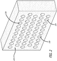
- FIG. 2 is a diagram showing a block 210 employed for the disclosed battery pack 310 (refer to FIG. 3 ), in accordance with at least one embodiment of the present disclosure.
- the block 210 is shown to be formed to comprise a plurality of recesses 220 configured to receive the plurality of battery cells 110.
- a single battery cell 110 is disposed (e.g., inserted) into each recess 220 of the block 210.
- the recesses 220 are formed to be complimentary in shape and size to the battery cells 110.
- the block 210 is manufactured from a low density ceramic fiber reinforced foam, such as a low density oxide ceramic fiber reinforced foam.
- the low density ceramic fiber reinforced foam comprises alumina-borosilicate.
- the low density ceramic fiber reinforced foam is a Boeing Rigid Insulation (BRI) material.
- the foam is porous (e.g., an open cell foam) such that a gas (e.g., air) or a liquid (e.g., water or a coolant) may pass through the block 210 to cool the battery cells 110.
- the block 210 may also be formed to allow a gas or a liquid to pass (e.g., flow) in a predefined fashion (e.g., a zig-zag fashion, refer to FIG. 7 ) within the interior (or manifold) of the block 210.
- the block 210 may be formed to comprise at least one cooling hole (e.g., refer to cooling holes 710, 740 of block 730 of FIG. 7 ) (or slot) on a side (e.g., refer to an edge side 420a-d or face side 430a,b, of FIG. 4 ) of the block 210 such that a liquid or gas may pass through the block 210 via the cooling hole.
- at least one cooling hole (or slot) may be machined (instead of formed) on a side of the block 210 to allow for a liquid or gas may pass through the block 210 via the cooling hole.
- At least a portion of the surface (which may include the surface of the interior of at least one recess 220) of the block 210 is covered with a ceramic matrix composite (CMC) material (e.g., a ceramic slurry composite pre-impregnated (prepreg) with fibers, such as a ceramic slurry mix with 3M Nextel 312 ceramic fibers).
- CMC ceramic matrix composite
- preg ceramic slurry composite pre-impregnated
- the block 210 may be covered by the CMC material in a number of different ways to control gas or liquid flow.
- only the surface of one side of the block 210 may be covered with the CMC material, only the surface of the interior of the recesses 220 of the block 210 may be covered with the CMC material, only the surface of the interior of some of the recesses 220 of the block 210 may be covered with the CMC material, only the surface of one side of the block and the surface of the interior of the recesses 220 of the block 210 may be covered with the CMC material, or only the surface of two sides of the block and the surface of the interior of some of the recesses 220 of the block 210 may be covered with the CMC material.
- the CMC material is cured by firing the block 210 in a kiln after the CMC material is applied to the block 210.
- At least one cooling hole may be machined into at least one of the recesses 220 of the block 210 to enhance the heat exchange and/or cooling function. It should be noted that the cooling hole(s) (and/or slot(s)) may be machined within recesses 220 that have their interior surface covered with the CMC material, which has already been cured, and/or within recesses 220 that do not have their interior surface covered with the CMC material.
- the battery cells 110 are disposed within the recesses 220 of the block.
- At least a portion of the surface (which may include the surface of the interior of at least one recess 220) of the block 210 is local hardened.
- the battery cells 110 are disposed within the recesses 220 of the block.
- FIG. 3 is a diagram showing the fully constructed disclosed battery pack 310, in accordance with at least one embodiment of the present disclosure.
- each of the recesses 220 of the block 210 houses one of the battery cells 110 within the block 210.
- the top side of each of the battery cells 110 is flush with the surface of the first face side 430a of the block 210, and each of the battery cells 110 fits into a respective recess 220 such that there are no gaps in between each of the battery cells 110 and its respective recess 220.
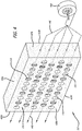
- FIG. 4 is a diagram showing a gas 440 pumped by a pump 410 into an edge side (e.g., a first edge side) 420a of the block 210 of the disclosed battery pack 310, in accordance with at least one embodiment of the present disclosure.
- a pump e.g., a blower
- a gas e.g., air
- FIG. 4 is a diagram showing a gas 440 pumped by a pump 410 into an edge side (e.g., a first edge side) 420a of the block 210 of the disclosed battery pack 310, in accordance with at least one embodiment of the present disclosure.
- a pump e.g., a blower
- a gas e.g., air
- various other different types of pumps may be employed for the pump 410 of the disclosed system including, but not limited to, a liquid pump (e.g., a water pump).
- the pump 410 may pump a liquid (e.g., water or coolant) into the block 210 rather than a gas 440 as is illustrated in FIG. 4 .
- the pump 410 is shown to be pumping a gas 440 into a first edge side 420a of the block 210.
- the pumped gas 440 travels within the porous material of the block 210, travels past the battery cells 110 to cool the battery cells 110 and exits out of the second edge side 420b of the block 210.
- the pump 410 may pump a gas 440 (or liquid) into various different sides of the block 210 other than the first edge side 420a of the block 210 as is depicted in FIG. 4 .
- the various other different sides of the block 210 that the gas 440 may be pumped into are the second edge side 420b, the top edge side 420c, the bottom edge side 420d (refer to FIG. 5 ), the first face side 430a (refer to FIG. 7 ), and the second face side 430b.
- FIG. 5 is a diagram showing a gas 440 pumped into another edge side (e.g., a bottom edge side) 420d of the block 210 of the disclosed battery pack 310, in accordance with at least one embodiment of the present disclosure.
- FIG. 5 (as well as FIGS. 6 and 7 ) does not specifically show a pump 410 (refer to FIG. 4 ) pumping the gas 440 into the block 210, it is understood that a pump 410 is being used to pump the gas 440.
- the gas 440 is pumped into a bottom edge side 420d of the block 210.
- the pumped gas 440 travels within the porous material of the block 210, travels past the battery cells 110 to cool the battery cells 110 and exits out of the top edge side 420c of the block 210.
- FIG. 6 is a diagram showing a gas 440 pumped into a face side (e.g., a first face side 430a) of the block 210 of the disclosed battery pack 310, in accordance with at least one embodiment of the present disclosure.
- the gas 440 is pumped into a first face side 430a of the block 210.
- the pumped gas 440 travels within the porous material of the block 210, travels past the battery cells 110 to cool the battery cells 110 and exits out of the second face side 430b of the block 210.
- FIG. 7 is a diagram showing a gas 440 pumped into a cooling hole 710 of the block 730 of the disclosed battery pack 720, in accordance with at least one embodiment of the present disclosure.
- the block 730 for the battery pack 720 of this figure is formed to allow a gas 440 (or a liquid) to pass (e.g., flow) in a predefined zig-zag fashion within the interior (or manifold) of the block 730.
- solid barriers 750 are formed within the porous block such that a gas (or liquid) will be forced to flow within the interior of the block 730 in a zig-zag fashion.
- cooling holes 710, 740 are formed (or alternatively machined) on the first edge side 420a and the second edge side 420b of the block 730.
- the gas 440 is pumped into the block 730 via cooling hole 710.
- the gas 440 then flows through the interior of the block 730 in a zig-zag fashion to cool the battery cells 110 and exits the block 730 via cooling hole 740.
- cooling holes 710, 740 in FIG. 7 are illustrated to be circular shaped cooling holes. However, in other embodiments, various different shapes other than a circular shape may be employed for cooling holes 710, 740 formed (or machined) on the block 730. Other shapes that the cooling holes 710, 740 may be formed to be include, but are not limited to, a rectangular shaped cooling hole (e.g., a slot), a square shaped cooling hole, and a triangular shaped cooling hole.
- FIG. 8 is a flow chart showing a method 800 of manufacturing the disclosed battery pack, in accordance with at least one embodiment of the present disclosure.
- a block comprising a plurality of recesses configured to receive a plurality of battery cell is formed 820.
- the block is optionally formed to allow a gas or a liquid to pass (e.g., flow) in a predefined fashion (e.g., a zig-zag fashion) within the interior of the block.
- at least one cooling hole is optionally machined within a side of the block to allow for a gas or liquid to pass (e.g., flow) through the interior of the block 830.
- CMC ceramic matrix composite
- FIG. 9 is a flow chart showing another method 900 of manufacturing the disclosed battery pack, in accordance with at least one embodiment of the present disclosure.
- a block comprising a plurality of recesses configured to receive a plurality of battery cell is formed 920.
- the block is optionally formed to allow a gas or a liquid to pass (e.g., flow) in a predefined fashion (e.g., a zig-zag fashion) within the interior of the block.
- at least one cooling hole is optionally machined within a side of the block to allow for a gas or liquid to pass (e.g., flow) through the interior of the block 930.
- the method 900 ends 960.
Landscapes
- Chemical & Material Sciences (AREA)
- Chemical Kinetics & Catalysis (AREA)
- Electrochemistry (AREA)
- General Chemical & Material Sciences (AREA)
- Engineering & Computer Science (AREA)
- Manufacturing & Machinery (AREA)
- Materials Engineering (AREA)
- Inorganic Chemistry (AREA)
- Ceramic Engineering (AREA)
- Structural Engineering (AREA)
- Organic Chemistry (AREA)
- Public Health (AREA)
- Business, Economics & Management (AREA)
- Emergency Management (AREA)
- Health & Medical Sciences (AREA)
- Secondary Cells (AREA)
- Battery Mounting, Suspending (AREA)
Abstract
Description
- The present disclosure relates to batteries. In particular, the present disclosure relates to multifunctional battery packaging and insulation.
- Present day lithium ion battery cells are susceptible to thermal runaway. This presents a considerable safety issue in the form of fire. Likewise, one battery cell exotherming (i.e. experiencing thermal runaway) can cause the temperature in the adjacent battery cells to increase, thus causing a cascading effect of exotherming battery cells among an entire array of battery cells. In addition, it is preferred to keep the battery cells at a constant temperature throughout their life cycle to ensure peak performance and to prevent premature battery cell failure.
- Present solutions include either no insulation or encasing the battery cell array in a block of high density polyurethane (HDPE) or other similar plastic materials. While this solution attempts to prevent the cascading effect of individual battery cell runaway, it is prohibitively heavy and does not allow for adequate cooling due to the impervious nature of the HDPE. In essence, the battery cells are wrapped in a solid cocoon of nonporous polyethylene thermoplastic, which acts to contain heat rather than to dissipate it.
- In light of the foregoing, there is a need for an improved battery cell packaging and insulation design.
- The present disclosure relates to a method, system, and apparatus for multifunctional battery packaging and insulation. In one or more embodiments, a battery pack comprises a plurality of battery cells. The battery pack further comprises a block comprising a plurality of recesses formed within the block, where each of the recesses respectively houses one of the battery cells within the block. In one or more embodiments, the block comprises a low density ceramic fiber reinforced foam that is porous such that a gas or liquid may pass through the block to cool the battery cells.
- In one or more embodiments, at least one of the battery cells is a lithium-ion battery cell, a nickel-cadmium battery cell, a nickel-zinc battery cell, and/or a nickel-metal hydride battery cell. In some embodiments, the lithium-ion battery cell is a lithium cobalt oxide battery cell, a lithium manganese oxide battery cell, a lithium iron phosphate battery cell, a lithium nickel manganese cobalt oxide battery cell, a lithium nickel cobalt aluminum oxide battery cell, a lithium titanate battery cell, or a lithium-sulfur battery cell.
- In at least one embodiment, the low density ceramic fiber reinforced foam is a low density oxide ceramic fiber reinforced foam. In some embodiments, the low density ceramic fiber reinforced foam comprises alumina-borosilicate.
- In one or more embodiments, at least a portion of a surface of the block is local hardened.
- In at least one embodiment, at least a portion of a surface of the block is covered with a ceramic matrix composite (CMC) material. In one or more embodiments, the ceramic matrix composite (CMC) material comprises a ceramic slurry composite pre-impregnated (prepreg) with fibers. In some embodiments, the ceramic matrix composite material (CMC) is cured via firing the block in a kiln.
- In one or more embodiments, an interior surface of at least one of the recesses of the block is coated with the ceramic matrix composite (CMC) material.
- In at least one embodiment, the block is configured to pass the gas or the liquid in a zig-zag fashion within an interior of the block. In some embodiments, at least one cooling hole is machined or formed within the block such that a gas or liquid may pass through the block via the at least one cooling hole.
- In one or more embodiments, a system for cooling a battery pack comprises the battery pack comprising a plurality of battery cells and a block comprising a plurality of recesses formed within the block, where each of the recesses respectively houses one of the battery cells within the block. In one or more embodiments, the block comprises a low density ceramic fiber reinforced foam that is porous such that a gas or liquid may pass through the block. The system further comprises a pump to pump the gas or the liquid through the block to cool the battery cells within the block.
- In at least one embodiment, the pump is configured to pump the gas or the liquid into a face side or into an edge side of the block. In one or more embodiments, the pump is configured to pump the gas or the liquid into at least one cooling hole, which is machined or formed within the block. In some embodiments, the block is configured to allow the gas or the liquid pass in a zig-zag fashion within an interior of the block.
- In one or more embodiments, a method for cooling a battery pack comprises pumping, via a pump, a gas or liquid through a block of the battery pack to cool a plurality of battery cells within the battery pack. In at least one embodiment, a plurality of recesses is formed within the block, and each of the recesses respectively houses one of the battery cells within the block. In some embodiments, the block comprises a low density ceramic fiber reinforced foam that is porous such that the gas or the liquid may pass through the block.
- In at least one embodiment, a method of manufacturing a battery pack, comprises forming a block comprising a plurality of recesses configured to receive a plurality of battery cells, where the block comprises a low density ceramic fiber reinforced foam that is porous such that a gas or liquid may pass through the block. The method further comprises covering at least a portion of a surface of the block with a ceramic matrix composite (CMC) material. Also, the method comprises firing the block in a kiln to cure the CMC material. Further the method comprises disposing one of the battery cells within each of the recesses within the block.
- In one or more embodiments, the method further comprises machining or forming at least one cooling hole within the block to allow for a gas or liquid to pass through the block.
- In at least one embodiment, the method further comprises forming the block such that the block is configured to pass the gas or the liquid in a zig-zag fashion within an interior of the block.
- The features, functions, and advantages can be achieved independently in various embodiments of the present disclosure or may be combined in yet other embodiments.
- These and other features, aspects, and advantages of the present disclosure will become better understood with regard to the following description, appended claims, and accompanying drawings where:
-
FIG. 1 is a diagram showing a plurality of battery cells employed for the disclosed battery pack, in accordance with at least one embodiment of the present disclosure. -
FIG. 2 is a diagram showing a block employed for the disclosed battery pack, in accordance with at least one embodiment of the present disclosure. -
FIG. 3 is a diagram showing the fully constructed disclosed battery pack, in accordance with at least one embodiment of the present disclosure. -
FIG. 4 is a diagram showing a gas pumped by a pump into an edge side of the block of the disclosed battery pack, in accordance with at least one embodiment of the present disclosure. -
FIG. 5 is a diagram showing a gas pumped into another edge side of the block of the disclosed battery pack, in accordance with at least one embodiment of the present disclosure. -
FIG. 6 is a diagram showing a gas pumped into a face side of the block of the disclosed battery pack, in accordance with at least one embodiment of the present disclosure. -
FIG. 7 is a diagram showing a gas pumped into a cooling hole of the block of the disclosed battery pack, in accordance with at least one embodiment of the present disclosure. -
FIG. 8 is a flow chart showing a method of manufacturing the disclosed battery pack, in accordance with at least one embodiment of the present disclosure. -
FIG. 9 is a flow chart showing another method of manufacturing the disclosed battery pack, in accordance with at least one embodiment of the present disclosure. - The methods and apparatus disclosed herein provide an operative system for multifunctional battery packaging and insulation. In one or more embodiments, the system of the present disclosure teaches
- As previously mentioned above, present day lithium ion battery cells are susceptible to thermal runaway. This presents a considerable safety issue in the form of high temperatures and fire. Likewise, if one battery cell experiences thermal runaway (which can be caused by a short within the battery cell), the heat and fire produced from the thermal runaway can cause the temperature in the adjacent battery cells to increase. This increase in temperature in the adjacent battery cells can cause a cascading effect of thermal runaway within the entire array of battery cells. In addition, it is preferred to maintain the battery cells at a constant temperature throughout their life cycle to ensure peak performance of the battery cells and to prevent premature battery cell failure.
- Present solutions include either no insulation or encasing the battery cell array in a block of high density polyurethane (HDPE) or other similar plastic materials. While this solution attempts to prevent the cascading effect of individual battery cell runaway, it is prohibitively heavy and does not allow for adequate cooling due to the impervious nature of the HDPE. In essence, the battery cells are wrapped in a solid cocoon of nonporous polyethylene thermoplastic, which acts to contain heat (i.e. acts to insulate the heat) rather than to dissipate it. The block of HDPE (or other similar plastic material) is incapable of withstanding the temperatures exhibited during thermal runaway that can reach 1,100 degrees Fahrenheit.
- The present disclosure teaches a battery pack design comprising a battery cell array packaged within a block of low density ceramic fiber reinforced foam (e.g., low density oxide ceramic fiber reinforced foam) (e.g., comprising alumina-borosilicate). The low density ceramic fiber reinforced foam has a density range of approximately 8 to 30 pounds per cubic foot (pcf), and comprises approximately 95% to 98% air by volume. The block may be bare mineral, or local surface hardened, or even covered selectively in a ceramic slurry composite prepreg (e.g., a ceramic slurry pre-impregnated with fibers) and subsequently kiln fired. In one or more embodiments, a cooling gas (e.g., air) or liquid (e.g., water or coolant) may be pumped into (and/or forced though) the porous block (e.g., through the open cell foam of the block) of the disclosed battery pack to help maintain more of a constant temperature battery cell operating range.
- The disclosed battery pack design of encasing a battery cell array within a block of low density ceramic fiber reinforced foam provides several advantages. Firstly, the design allows for isolation of the battery cells such that, in the event an individual battery cell experiences thermal runaway, the fire is contained within the battery cell and the heat produced by that battery cell does not heat any adjacent battery cells. Secondly, the porous nature of the block of the design allows for cooling of the battery cells via a forced air exchange applied to the block. Thirdly, the disclosed battery pack design weighs (e.g., approximately 8 to 20 pounds per cubic foot) much less than conventional battery pack designs employing HDPE (e.g., approximately 50 pounds per cubic foot). Fourthly, the disclosed battery pack design can withstand much higher temperatures (e.g., can withstand temperatures greater than 2000 degrees Fahrenheit) than conventional battery pack designs employing HDPE, which is incapable of withstanding typical temperatures exhibited during runaway that can reach 1,100 degrees Fahrenheit.
- In the following description, numerous details are set forth in order to provide a more thorough description of the system. It will be apparent, however, to one skilled in the art, that the disclosed system may be practiced without these specific details. In the other instances, well known features have not been described in detail, so as not to unnecessarily obscure the system.
- Embodiments of the present disclosure may be described herein in terms of functional and/or logical components and various processing steps. It should be appreciated that such components may be realized by any number of hardware, software, and/or firmware components configured to perform the specified functions. For example, an embodiment of the present disclosure may employ various integrated circuit components (e.g., memory elements, digital signal processing elements, logic elements, look-up tables, or the like), which may carry out a variety of functions under the control of one or more processors, microprocessors, or other control devices. In addition, those skilled in the art will appreciate that embodiments of the present disclosure may be practiced in conjunction with other components, and that the systems described herein are merely example embodiments of the present disclosure.
- For the sake of brevity, conventional techniques and components related to battery packs, and other functional aspects of the system (and the individual operating components of the systems) may not be described in detail herein. Furthermore, the connecting lines shown in the various figures contained herein are intended to represent example functional relationships and/or physical couplings between the various elements. It should be noted that many alternative or additional functional relationships or physical connections may be present in one or more embodiments of the present disclosure.
-
FIG. 1 is a diagram showing a plurality ofbattery cells 110 employed for the disclosed battery pack 310 (refer toFIG. 3 ), in accordance with at least one embodiment of the present disclosure. In this figure, thebattery cells 110 are shown to be cylindrical in shape. However, it should be noted that in other embodiments, thebattery cells 110 may be of various different shapes than the cylindrical shape as is depicted inFIG. 1 . - Various different types of battery cells may be employed for the
battery cells 110 of the disclosedbattery pack 310 including, but not limited to, lithium-ion battery cells, nickel-cadmium battery cells, nickel-zinc battery cells, and/or nickel-metal hydride battery cells. When lithium-ion battery cells are employed for thebattery cells 110, various different types of lithium-ion battery cells may be employed for thebattery cells 110 of the disclosedbattery pack 310 including, but not limited to, lithium cobalt oxide battery cells, lithium manganese oxide battery cells, lithium iron phosphate battery cells, lithium nickel manganese cobalt oxide battery cells, lithium nickel cobalt aluminum oxide battery cells, lithium titanate battery cells, or lithium-sulfur battery cells. -
FIG. 2 is a diagram showing ablock 210 employed for the disclosed battery pack 310 (refer toFIG. 3 ), in accordance with at least one embodiment of the present disclosure. In this figure, theblock 210 is shown to be formed to comprise a plurality ofrecesses 220 configured to receive the plurality ofbattery cells 110. For the disclosedbattery pack 310, asingle battery cell 110 is disposed (e.g., inserted) into eachrecess 220 of theblock 210. As such, therecesses 220 are formed to be complimentary in shape and size to thebattery cells 110. - The
block 210 is manufactured from a low density ceramic fiber reinforced foam, such as a low density oxide ceramic fiber reinforced foam. In one or more embodiments, the low density ceramic fiber reinforced foam comprises alumina-borosilicate. In at least one embodiment, the low density ceramic fiber reinforced foam is a Boeing Rigid Insulation (BRI) material. The foam is porous (e.g., an open cell foam) such that a gas (e.g., air) or a liquid (e.g., water or a coolant) may pass through theblock 210 to cool thebattery cells 110. - In one or more embodiments, the
block 210 may also be formed to allow a gas or a liquid to pass (e.g., flow) in a predefined fashion (e.g., a zig-zag fashion, refer toFIG. 7 ) within the interior (or manifold) of theblock 210. In some embodiments, theblock 210 may be formed to comprise at least one cooling hole (e.g., refer to coolingholes block 730 ofFIG. 7 ) (or slot) on a side (e.g., refer to anedge side 420a-d or faceside 430a,b, ofFIG. 4 ) of theblock 210 such that a liquid or gas may pass through theblock 210 via the cooling hole. Also, at least one cooling hole (or slot) may be machined (instead of formed) on a side of theblock 210 to allow for a liquid or gas may pass through theblock 210 via the cooling hole. - In one or more embodiments, at least a portion of the surface (which may include the surface of the interior of at least one recess 220) of the
block 210 is covered with a ceramic matrix composite (CMC) material (e.g., a ceramic slurry composite pre-impregnated (prepreg) with fibers, such as a ceramic slurry mix with 3M Nextel 312 ceramic fibers). As such, theblock 210 may be covered by the CMC material in a number of different ways to control gas or liquid flow. For example, but not limited by these examples, only the surface of one side of theblock 210 may be covered with the CMC material, only the surface of the interior of therecesses 220 of theblock 210 may be covered with the CMC material, only the surface of the interior of some of therecesses 220 of theblock 210 may be covered with the CMC material, only the surface of one side of the block and the surface of the interior of therecesses 220 of theblock 210 may be covered with the CMC material, or only the surface of two sides of the block and the surface of the interior of some of therecesses 220 of theblock 210 may be covered with the CMC material. The CMC material is cured by firing theblock 210 in a kiln after the CMC material is applied to theblock 210. - In one or more embodiments, at least one cooling hole (and/or slot) may be machined into at least one of the
recesses 220 of theblock 210 to enhance the heat exchange and/or cooling function. It should be noted that the cooling hole(s) (and/or slot(s)) may be machined withinrecesses 220 that have their interior surface covered with the CMC material, which has already been cured, and/or withinrecesses 220 that do not have their interior surface covered with the CMC material. - Then, the
battery cells 110 are disposed within therecesses 220 of the block. - In other embodiments, at least a portion of the surface (which may include the surface of the interior of at least one recess 220) of the
block 210 is local hardened. For these embodiments, after at least a portion of the surface of theblock 210 is local hardened, thebattery cells 110 are disposed within therecesses 220 of the block. -
FIG. 3 is a diagram showing the fully constructed disclosedbattery pack 310, in accordance with at least one embodiment of the present disclosure. In this figure, each of therecesses 220 of theblock 210 houses one of thebattery cells 110 within theblock 210. As is shown in this figure, the top side of each of thebattery cells 110 is flush with the surface of thefirst face side 430a of theblock 210, and each of thebattery cells 110 fits into arespective recess 220 such that there are no gaps in between each of thebattery cells 110 and itsrespective recess 220. -
FIG. 4 is a diagram showing agas 440 pumped by apump 410 into an edge side (e.g., a first edge side) 420a of theblock 210 of the disclosedbattery pack 310, in accordance with at least one embodiment of the present disclosure. In this figure, a pump (e.g., a blower) 410 is shown to be pumping a gas (e.g., air) into theblock 210 in order to cool thebattery cells 110 housed within theblock 210. It should be noted that although thepump 410 is depicted as a blower inFIG. 4 , in various other embodiments, various other different types of pumps may be employed for thepump 410 of the disclosed system including, but not limited to, a liquid pump (e.g., a water pump). In addition, in other embodiments, thepump 410 may pump a liquid (e.g., water or coolant) into theblock 210 rather than agas 440 as is illustrated inFIG. 4 . - In
FIG. 4 , thepump 410 is shown to be pumping agas 440 into afirst edge side 420a of theblock 210. The pumpedgas 440 travels within the porous material of theblock 210, travels past thebattery cells 110 to cool thebattery cells 110 and exits out of thesecond edge side 420b of theblock 210. It should be noted that in other embodiments, thepump 410 may pump a gas 440 (or liquid) into various different sides of theblock 210 other than thefirst edge side 420a of theblock 210 as is depicted inFIG. 4 . The various other different sides of theblock 210 that thegas 440 may be pumped into are thesecond edge side 420b, thetop edge side 420c, thebottom edge side 420d (refer toFIG. 5 ), thefirst face side 430a (refer toFIG. 7 ), and thesecond face side 430b. -
FIG. 5 is a diagram showing agas 440 pumped into another edge side (e.g., a bottom edge side) 420d of theblock 210 of the disclosedbattery pack 310, in accordance with at least one embodiment of the present disclosure. It should be noted that althoughFIG. 5 (as well asFIGS. 6 and7 ) does not specifically show a pump 410 (refer toFIG. 4 ) pumping thegas 440 into theblock 210, it is understood that apump 410 is being used to pump thegas 440. InFIG. 5 , thegas 440 is pumped into abottom edge side 420d of theblock 210. The pumpedgas 440 travels within the porous material of theblock 210, travels past thebattery cells 110 to cool thebattery cells 110 and exits out of thetop edge side 420c of theblock 210. -
FIG. 6 is a diagram showing agas 440 pumped into a face side (e.g., afirst face side 430a) of theblock 210 of the disclosedbattery pack 310, in accordance with at least one embodiment of the present disclosure. InFIG. 6 , thegas 440 is pumped into afirst face side 430a of theblock 210. The pumpedgas 440 travels within the porous material of theblock 210, travels past thebattery cells 110 to cool thebattery cells 110 and exits out of thesecond face side 430b of theblock 210. -
FIG. 7 is a diagram showing agas 440 pumped into acooling hole 710 of theblock 730 of the disclosed battery pack 720, in accordance with at least one embodiment of the present disclosure. Theblock 730 for the battery pack 720 of this figure is formed to allow a gas 440 (or a liquid) to pass (e.g., flow) in a predefined zig-zag fashion within the interior (or manifold) of theblock 730. In particular,solid barriers 750 are formed within the porous block such that a gas (or liquid) will be forced to flow within the interior of theblock 730 in a zig-zag fashion. - Also shown in
FIG. 7 , cooling holes 710, 740 are formed (or alternatively machined) on thefirst edge side 420a and thesecond edge side 420b of theblock 730. Thegas 440 is pumped into theblock 730 viacooling hole 710. Thegas 440 then flows through the interior of theblock 730 in a zig-zag fashion to cool thebattery cells 110 and exits theblock 730 viacooling hole 740. - It should be noted that the cooling holes 710, 740 in
FIG. 7 are illustrated to be circular shaped cooling holes. However, in other embodiments, various different shapes other than a circular shape may be employed for coolingholes block 730. Other shapes that the cooling holes 710, 740 may be formed to be include, but are not limited to, a rectangular shaped cooling hole (e.g., a slot), a square shaped cooling hole, and a triangular shaped cooling hole. -
FIG. 8 is a flow chart showing amethod 800 of manufacturing the disclosed battery pack, in accordance with at least one embodiment of the present disclosure. At thestart 810 of themethod 800, a block comprising a plurality of recesses configured to receive a plurality of battery cell is formed 820. During the forming of the block, the block is optionally formed to allow a gas or a liquid to pass (e.g., flow) in a predefined fashion (e.g., a zig-zag fashion) within the interior of the block. Also, at least one cooling hole is optionally machined within a side of the block to allow for a gas or liquid to pass (e.g., flow) through the interior of theblock 830. - Then, at least a portion of the surface of the block is covered with a ceramic matrix composite (CMC)
material 840. The block is then fired in a kiln to cure theCMC material 850. Then, a battery cell is disposed (e.g., inserted) within each of the recesses formed within theblock 860. Then, themethod 800 ends 870. -
FIG. 9 is a flow chart showing anothermethod 900 of manufacturing the disclosed battery pack, in accordance with at least one embodiment of the present disclosure. At thestart 910 of themethod 900, a block comprising a plurality of recesses configured to receive a plurality of battery cell is formed 920. During the forming of the block, the block is optionally formed to allow a gas or a liquid to pass (e.g., flow) in a predefined fashion (e.g., a zig-zag fashion) within the interior of the block. Also, at least one cooling hole is optionally machined within a side of the block to allow for a gas or liquid to pass (e.g., flow) through the interior of theblock 930. - Then, at least a portion of the surface of the block is local hardened 940. Then, a battery cell is disposed (e.g., inserted) within each of the recesses formed within the
block 950. Then, themethod 900 ends 960. - Although particular embodiments have been shown and described, it should be understood that the above discussion is not intended to limit the scope of these embodiments. While embodiments and variations of the many aspects of the disclosure have been disclosed and described herein, such disclosure is provided for purposes of explanation and illustration only. Thus, various changes and modifications may be made without departing from the scope of the claims.
- Where methods described above indicate certain events occurring in certain order, those of ordinary skill in the art having the benefit of this disclosure would recognize that the ordering may be modified and that such modifications are in accordance with the variations of the present disclosure. Additionally, parts of methods may be performed concurrently in a parallel process when possible, as well as performed sequentially. In addition, more steps or less steps of the methods may be performed.
- Accordingly, embodiments are intended to exemplify alternatives, modifications, and equivalents that may fall within the scope of the claims.
- Further, the disclosure comprises embodiments according to the following clauses:
- Clause 1 :A battery pack apparatus (310), the apparatus (310) comprising: a plurality of battery cells (110); and
a block (210) comprising a plurality of recesses (220) formed within the block (210), wherein each of the recesses (220) respectively houses one of the battery cells (110) within the block (210), and
wherein the block (210) comprises a low density ceramic fiber reinforced foam that is porous such that a gas (440) or liquid may pass through the block (210). - Clause 2: The apparatus of clause 1, wherein at least one of the battery cells (110) is at least one of a lithium-ion battery cell, a nickel-cadmium battery cell, a nickel-zinc battery cell, or a nickel-metal hydride battery cell.
- Clause 3: The apparatus of clause 2, wherein the lithium-ion battery cell is a lithium cobalt oxide battery cell, a lithium manganese oxide battery cell, a lithium iron phosphate battery cell, a lithium nickel manganese cobalt oxide battery cell, a lithium nickel cobalt aluminum oxide battery cell, a lithium titanate battery cell, or a lithium-sulfur battery cell.
- Clause 4: The apparatus of clause 1, wherein the low density ceramic fiber reinforced foam is a low density oxide ceramic fiber reinforced foam.
- Clause 5: The apparatus of clause 1, wherein the low density ceramic fiber reinforced foam comprises alumina-borosilicate.
- Clause 6: The apparatus of clause 1, wherein at least a portion of a surface of the block (210) is local hardened.
- Clause 7: The apparatus of clause 1, wherein at least a portion of a surface of the block (210) is covered with a ceramic matrix composite (CMC) material.
- Clause 8: The apparatus of clause 7, wherein the ceramic matrix composite (CMC) material comprises a ceramic slurry composite pre-impregnated (prepreg) with fibers.
- Clause 9: The apparatus of clause 7, wherein the ceramic matrix composite material (CMC) is cured via firing the block (210) in a kiln.
- Clause 10: The apparatus of clause 7, wherein an interior surface of at least one of the recesses (220) of the block (210) is coated with the ceramic matrix composite (CMC) material.
- Clause 11: The apparatus of clause 1, wherein the block (210) is configured to pass the gas (440) or the liquid in a zig-zag fashion within an interior of the block (210).
- Clause 12: The apparatus of clause 1, wherein at least one cooling hole (710, 740) is machined or formed within the block (210) such that a gas (440) or liquid may pass through the block (210) via the at least one cooling hole (710, 740).
- Clause 13: A system for cooling a battery pack (310), the system comprising:
the battery pack (310) comprising a plurality of battery cells (110) and a block (210) comprising a plurality of recesses (220) formed within the block (210), wherein each of the recesses (220) respectively houses one of the battery cells (110) within the block (210), and wherein the block (210) comprises a low density ceramic fiber reinforced foam that is porous such that a gas (440) or liquid may pass through the block (210); and a pump (410) to pump the gas (440) or the liquid through the block (210) to cool the battery cells (110) within the block (210). - Clause 14: The system of clause 13, wherein the pump (410) is configured to pump the gas (440) or the liquid into a face side (430a, 430b) or into an edge side (420a, 420b, 420c, 420d) of the block.
- Clause 15: The system of clause 13, wherein the pump (410) is configured to pump the gas (440) or the liquid into at least one cooling hole (710, 740), which is machined or formed within the block (210).
- Clause 16: The system of clause 13, wherein the block (210) is configured to allow the gas (440) or the liquid pass in a zig-zag fashion within an interior of the block (210).
- Clause 17: A method for cooling a battery pack (310), the method comprising:
- pumping, via a pump (410), a gas (440) or liquid through a block (210) of the battery pack (310) to cool a plurality of battery cells (110) within the battery pack (310),
- wherein a plurality of recesses (220) is formed within the block (210), and each of
- the recesses (220) respectively houses one of the battery cells (110) within the block (210), and wherein the block (210) comprises a low density ceramic fiber reinforced foam that is porous such that the gas (440) or the liquid may pass through the block (210).
- Clause 18: A method of manufacturing a battery pack (310), the method comprising:
- forming a block (210) comprising a plurality of recesses (220) configured to receive a plurality of battery cells (110), wherein the block (220) comprises a low density ceramic fiber reinforced foam that is porous such that a gas (440) or liquid may pass through the block (220);
- covering at least a portion of a surface of the block (220) with a ceramic matrix composite (CMC) material;
- firing the block (220) in a kiln to cure the CMC material; and
- disposing one of the battery cells (110) within each of the recesses (220) within the block (210).
- Clause 19: The method of clause 18, wherein the method further comprises machining or forming at least one cooling hole (710, 740) within the block (210) to allow for a gas (440) or liquid to pass through the block (210).
- Clause 20: The method of clause 18, wherein the method further comprises forming the block (210) such that the block (210) is configured to pass the gas (440) or the liquid in a zig-zag fashion within an interior of the block (210).
- Although certain illustrative embodiments and methods have been disclosed herein, it can be apparent from the foregoing disclosure to those skilled in the art that variations and modifications of such embodiments and methods can be made. Many other examples exist, each differing from others in matters of detail only. Accordingly, it is intended that this disclosure be limited only to the extent required by the appended claims and the rules and principles of applicable law.
Claims (15)
- A battery pack apparatus (310), the apparatus (310) comprising:a plurality of battery cells (110); anda block (210) comprising a plurality of recesses (220) formed within the block (210), wherein each of the recesses (220) respectively houses one of the battery cells (110) within the block (210), andwherein the block (210) comprises a low density ceramic fiber reinforced foam that is porous such that a gas (440) or liquid may pass through the block (210).
- The apparatus of claim 1, wherein at least one of the battery cells (110) is at least one of a lithium-ion battery cell, a nickel-cadmium battery cell, a nickel-zinc battery cell, or a nickel-metal hydride battery cell.
- The apparatus of claim 2, wherein the lithium-ion battery cell is a lithium cobalt oxide battery cell, a lithium manganese oxide battery cell, a lithium iron phosphate battery cell, a lithium nickel manganese cobalt oxide battery cell, a lithium nickel cobalt aluminum oxide battery cell, a lithium titanate battery cell, or a lithium-sulfur battery cell.
- The apparatus of claim 1, wherein the low density ceramic fiber reinforced foam is a low density oxide ceramic fiber reinforced foam.
- The apparatus of claim 1, wherein the low density ceramic fiber reinforced foam comprises alumina-borosilicate.
- The apparatus of claim 1, wherein at least a portion of a surface of the block (210) is local hardened.
- The apparatus of claim 1, wherein at least a portion of a surface of the block (210) is covered with a ceramic matrix composite (CMC) material.
- The apparatus of claim 7, wherein the ceramic matrix composite (CMC) material comprises a ceramic slurry composite pre-impregnated (prepreg) with fibers.
- The apparatus of claim 7, wherein the ceramic matrix composite material (CMC) is cured via firing the block (210) in a kiln.
- The apparatus of claim 7, wherein an interior surface of at least one of the recesses (220) of the block (210) is coated with the ceramic matrix composite (CMC) material.
- The apparatus of claim 1, wherein the block (210) is configured to pass the gas (440) or the liquid in a zig-zag fashion within an interior of the block (210).
- The apparatus of claim 1, wherein at least one cooling hole (710, 740) is machined or formed within the block (210) such that a gas (440) or liquid may pass through the block (210) via the at least one cooling hole (710, 740).
- A method for cooling a battery pack (310), the method comprising:pumping, via a pump (410), a gas (440) or liquid through a block (210) of the battery pack (310) to cool a plurality of battery cells (110) within the battery pack (310),wherein a plurality of recesses (220) is formed within the block (210), and each of the recesses (220) respectively houses one of the battery cells (110) within the block (210), and wherein the block (210) comprises a low density ceramic fiber reinforced foam that is porous such that the gas (440) or the liquid may pass through the block (210).
- A method of manufacturing a battery pack (310), the method comprising:forming a block (210) comprising a plurality of recesses (220) configured to receive a plurality of battery cells (110), wherein the block (220) comprises a low density ceramic fiber reinforced foam that is porous such that a gas (440) or liquid may pass through the block (220);covering at least a portion of a surface of the block (220) with a ceramic matrix composite (CMC) material;firing the block (220) in a kiln to cure the CMC material; anddisposing one of the battery cells (110) within each of the recesses (220) within the block (210).
- The method of claim 18, wherein the method further comprises machining or forming at least one cooling hole (710, 740) within the block (210) to allow for a gas (440) or liquid to pass through the block (210).
Applications Claiming Priority (1)
| Application Number | Priority Date | Filing Date | Title |
|---|---|---|---|
| US16/183,093 US11367893B2 (en) | 2018-11-07 | 2018-11-07 | Multifunctional battery packaging and insulation |
Publications (1)
| Publication Number | Publication Date |
|---|---|
| EP3651234A1 true EP3651234A1 (en) | 2020-05-13 |
Family
ID=68470424
Family Applications (1)
| Application Number | Title | Priority Date | Filing Date |
|---|---|---|---|
| EP19207510.9A Pending EP3651234A1 (en) | 2018-11-07 | 2019-11-06 | Multifunctional battery packaging and insulation |
Country Status (8)
| Country | Link |
|---|---|
| US (1) | US11367893B2 (en) |
| EP (1) | EP3651234A1 (en) |
| JP (1) | JP7441634B2 (en) |
| KR (1) | KR102851440B1 (en) |
| CN (1) | CN111162320B (en) |
| AU (1) | AU2019261717B2 (en) |
| CA (1) | CA3061040C (en) |
| TW (1) | TWI855004B (en) |
Cited By (1)
| Publication number | Priority date | Publication date | Assignee | Title |
|---|---|---|---|---|
| GB2606481A (en) * | 2022-07-06 | 2022-11-09 | Darchem Engineering Ltd | Enclosure |
Families Citing this family (2)
| Publication number | Priority date | Publication date | Assignee | Title |
|---|---|---|---|---|
| KR102909624B1 (en) | 2020-11-16 | 2026-01-08 | 주식회사 엘지에너지솔루션 | Cell Module Having Guide Frame and Its Manufacturing Method |
| EP4156392B1 (en) * | 2021-09-23 | 2025-07-23 | Samsung SDI Co., Ltd. | Battery cell holder for transport of battery cells and a battery pack comprising the same |
Citations (5)
| Publication number | Priority date | Publication date | Assignee | Title |
|---|---|---|---|---|
| US6479185B1 (en) * | 2000-04-04 | 2002-11-12 | Moltech Power Systems, Inc. | Extended life battery pack with active cooling |
| DE102009001592A1 (en) * | 2009-03-17 | 2010-09-23 | Robert Bosch Gmbh | Power supply unit comprises one or multiple energy cell units embedded partially in porous body, where porous body is made of material with certain thermal conductivity |
| US20120003508A1 (en) * | 2010-07-02 | 2012-01-05 | Saft | Battery of electrochemical generators comprising a foam as inter-generator filler material |
| WO2015179625A1 (en) * | 2014-05-21 | 2015-11-26 | Cadenza Innovation, Llc | Lithium ion battery with thermal runaway protection |
| CN108736102A (en) * | 2018-07-05 | 2018-11-02 | 江苏泛亚微透科技股份有限公司 | The elastic silica aerogel component of new-energy automobile lithium-ion-power cell heat conduction |
Family Cites Families (16)
| Publication number | Priority date | Publication date | Assignee | Title |
|---|---|---|---|---|
| US5167271A (en) * | 1988-10-20 | 1992-12-01 | Lange Frederick F | Method to produce ceramic reinforced or ceramic-metal matrix composite articles |
| WO2003043954A1 (en) * | 2001-11-19 | 2003-05-30 | Stanton Advanced Ceramics Llc | Thermal shock resistant ceramic composites |
| US7153464B2 (en) * | 2003-12-01 | 2006-12-26 | General Electric Company | Method of making porous ceramic matrix composites |
| JP2010211963A (en) | 2009-03-06 | 2010-09-24 | Toyota Motor Corp | Power storage apparatus |
| KR101143279B1 (en) * | 2009-08-20 | 2012-05-11 | 주식회사 엘지화학 | Battery Pack Having Novel Cooling Structure |
| KR101055464B1 (en) * | 2009-09-10 | 2011-08-08 | 삼성전기주식회사 | Solid Oxide Fuel Cells and Solid Oxide Fuel Cell Bundles |
| US8443922B2 (en) | 2009-10-07 | 2013-05-21 | The Boeing Company | Containment device and method for containing energy storage devices |
| JP2014022264A (en) | 2012-07-20 | 2014-02-03 | Chia Yuan Li | Vehicle battery with four functions of water proof, fire protection, vibration isolation and explosion protection and manufacturing method thereof |
| KR20170062555A (en) * | 2012-10-11 | 2017-06-07 | 카덴차 이노베이션, 인크 | Lithium ion battery |
| US10790489B2 (en) * | 2012-10-11 | 2020-09-29 | Cadenza Innovation, Inc. | Lithium ion battery |
| US20170015592A1 (en) | 2014-03-14 | 2017-01-19 | General Electric Company | Process of producing ceramic matrix composites and ceramic matrix composites formed thereby |
| US20160218336A1 (en) * | 2015-01-28 | 2016-07-28 | Motorola Solutions, Inc | Method and apparatus for assembling cells in a battery pack to control thermal release |
| EP3347932B1 (en) | 2015-09-11 | 2020-11-04 | Teledyne Scientific & Imaging, LLC | Multi-functional high temperature structure for thermal management and prevention of explosion propagation |
| EP3580790B1 (en) * | 2017-02-08 | 2024-01-24 | Elkem Silicones USA Corp. | Secondary battery pack with improved thermal management |
| US10256443B2 (en) | 2017-02-28 | 2019-04-09 | Murata Manufactruing Co., Ltd. | Battery pack, electric power tool, and electronic apparatus |
| WO2018195303A1 (en) * | 2017-04-19 | 2018-10-25 | Unifrax I Llc | Insulation barrier for electrochemical battery and electrochemical battery including same |
-
2018
- 2018-11-07 US US16/183,093 patent/US11367893B2/en active Active
-
2019
- 2019-11-05 TW TW108140045A patent/TWI855004B/en active
- 2019-11-06 EP EP19207510.9A patent/EP3651234A1/en active Pending
- 2019-11-06 CA CA3061040A patent/CA3061040C/en active Active
- 2019-11-06 KR KR1020190141057A patent/KR102851440B1/en active Active
- 2019-11-06 AU AU2019261717A patent/AU2019261717B2/en active Active
- 2019-11-07 JP JP2019202099A patent/JP7441634B2/en active Active
- 2019-11-07 CN CN201911080277.9A patent/CN111162320B/en active Active
Patent Citations (5)
| Publication number | Priority date | Publication date | Assignee | Title |
|---|---|---|---|---|
| US6479185B1 (en) * | 2000-04-04 | 2002-11-12 | Moltech Power Systems, Inc. | Extended life battery pack with active cooling |
| DE102009001592A1 (en) * | 2009-03-17 | 2010-09-23 | Robert Bosch Gmbh | Power supply unit comprises one or multiple energy cell units embedded partially in porous body, where porous body is made of material with certain thermal conductivity |
| US20120003508A1 (en) * | 2010-07-02 | 2012-01-05 | Saft | Battery of electrochemical generators comprising a foam as inter-generator filler material |
| WO2015179625A1 (en) * | 2014-05-21 | 2015-11-26 | Cadenza Innovation, Llc | Lithium ion battery with thermal runaway protection |
| CN108736102A (en) * | 2018-07-05 | 2018-11-02 | 江苏泛亚微透科技股份有限公司 | The elastic silica aerogel component of new-energy automobile lithium-ion-power cell heat conduction |
Non-Patent Citations (2)
| Title |
|---|
| ANONYMOUS: "Ceramic matrix composite - Wikipedia", 28 May 2016 (2016-05-28), XP055390873, Retrieved from the Internet <URL:https://en.wikipedia.org/w/index.php?title=Ceramic_matrix_composite&oldid=722547687> [retrieved on 20170714] * |
| ANONYMOUS: "Glass fiber - Wikipedia", 14 May 2018 (2018-05-14), pages 1 - 9, XP093039989, Retrieved from the Internet <URL:https://en.wikipedia.org/w/index.php?title=Glass_fiber&oldid=841219609> [retrieved on 20230418] * |
Cited By (3)
| Publication number | Priority date | Publication date | Assignee | Title |
|---|---|---|---|---|
| GB2606481A (en) * | 2022-07-06 | 2022-11-09 | Darchem Engineering Ltd | Enclosure |
| WO2024009105A3 (en) * | 2022-07-06 | 2024-02-15 | Darchem Engineering Limited | Enclosure |
| GB2606481B (en) * | 2022-07-06 | 2024-06-26 | Darchem Engineering Ltd | A ceramic matrix composite enclosure for an electrochemical power unit |
Also Published As
| Publication number | Publication date |
|---|---|
| US20200144658A1 (en) | 2020-05-07 |
| US11367893B2 (en) | 2022-06-21 |
| TW202029556A (en) | 2020-08-01 |
| JP2020092084A (en) | 2020-06-11 |
| JP7441634B2 (en) | 2024-03-01 |
| TWI855004B (en) | 2024-09-11 |
| CN111162320B (en) | 2024-04-02 |
| AU2019261717A1 (en) | 2020-05-21 |
| AU2019261717B2 (en) | 2025-03-27 |
| BR102019023285A2 (en) | 2020-05-26 |
| KR102851440B1 (en) | 2025-08-26 |
| CN111162320A (en) | 2020-05-15 |
| CA3061040A1 (en) | 2020-05-07 |
| KR20200053426A (en) | 2020-05-18 |
| CA3061040C (en) | 2024-03-12 |
Similar Documents
| Publication | Publication Date | Title |
|---|---|---|
| CA3061040C (en) | Multifunctional battery packaging and insulation | |
| EP1979961B1 (en) | Cooling structure of lithium ion secondary battery system | |
| KR102006430B1 (en) | Battery heat exchanger | |
| CN107331915B (en) | A kind of liquid cooling system and its liquid cooling package | |
| KR102275878B1 (en) | Method for producing cell module improved in characteristics of safety | |
| CN108520991B (en) | Novel thermal management system of vehicle-mounted lithium ion battery | |
| Sirikasemsuk et al. | Experimental investigation of the thermal management system of a battery pack using a thermoelectric air‐cooling module | |
| Rashidi et al. | Potentials of porous materials for temperature control of lithium-ion batteries | |
| CN109216605B (en) | Battery tray, battery pack assembly and vehicle with same | |
| JP5327016B2 (en) | Battery module | |
| CN118137064A (en) | Heat dissipation device for thermal runaway of battery pack | |
| CN104409794A (en) | Temperature management device of power battery pack of electric automobile, as well as manufacture method and application method thereof | |
| CN222355223U (en) | Cooling devices, battery components and electrical equipment | |
| WO2025145855A1 (en) | Battery module, battery with same, and electric device | |
| KR101872307B1 (en) | Method for Preparing Battery Pack Using Fixing Structure for Hot Melting and Battery Pack Prepared by Using the Same | |
| BR102019023285B1 (en) | Battery assembly apparatus, method and system for cooling the battery assembly, and method for manufacturing the battery assembly. | |
| CN109216602B (en) | Battery tray and battery pack assembly with same | |
| CN218783112U (en) | An immersion cooled battery | |
| CN223909993U (en) | Modular low-temperature high-power lithium battery baking protection basket | |
| US20240039076A1 (en) | Battery pack | |
| TW202324824A (en) | Thermal management module integrated with heat dissipation, rigidity and flame retardancy of battery including a high thermal conductivity polymer-based composite material shell, an upper cover plate, a lower cover plate and an inner cavity | |
| KR101306653B1 (en) | A method for manufacturing of bma with injection mesh | |
| CN222530505U (en) | Battery thermal management system with embedded composite cold plate | |
| CN206441839U (en) | A kind of battery module forced heating and cooled down | |
| CN222463035U (en) | Cooling system, battery pack and electric equipment |
Legal Events
| Date | Code | Title | Description |
|---|---|---|---|
| PUAI | Public reference made under article 153(3) epc to a published international application that has entered the european phase |
Free format text: ORIGINAL CODE: 0009012 |
|
| STAA | Information on the status of an ep patent application or granted ep patent |
Free format text: STATUS: THE APPLICATION HAS BEEN PUBLISHED |
|
| AK | Designated contracting states |
Kind code of ref document: A1 Designated state(s): AL AT BE BG CH CY CZ DE DK EE ES FI FR GB GR HR HU IE IS IT LI LT LU LV MC MK MT NL NO PL PT RO RS SE SI SK SM TR |
|
| AX | Request for extension of the european patent |
Extension state: BA ME |
|
| STAA | Information on the status of an ep patent application or granted ep patent |
Free format text: STATUS: REQUEST FOR EXAMINATION WAS MADE |
|
| 17P | Request for examination filed |
Effective date: 20201113 |
|
| RBV | Designated contracting states (corrected) |
Designated state(s): AL AT BE BG CH CY CZ DE DK EE ES FI FR GB GR HR HU IE IS IT LI LT LU LV MC MK MT NL NO PL PT RO RS SE SI SK SM TR |
|
| RAP3 | Party data changed (applicant data changed or rights of an application transferred) |
Owner name: THE BOEING COMPANY |
|
| STAA | Information on the status of an ep patent application or granted ep patent |
Free format text: STATUS: EXAMINATION IS IN PROGRESS |
|
| 17Q | First examination report despatched |
Effective date: 20230510 |