EP3651232A1 - Battery module - Google Patents
Battery module Download PDFInfo
- Publication number
- EP3651232A1 EP3651232A1 EP19171322.1A EP19171322A EP3651232A1 EP 3651232 A1 EP3651232 A1 EP 3651232A1 EP 19171322 A EP19171322 A EP 19171322A EP 3651232 A1 EP3651232 A1 EP 3651232A1
- Authority
- EP
- European Patent Office
- Prior art keywords
- cell
- module
- sides
- battery
- module frame
- Prior art date
- Legal status (The legal status is an assumption and is not a legal conclusion. Google has not performed a legal analysis and makes no representation as to the accuracy of the status listed.)
- Granted
Links
Images


Classifications
-
- H—ELECTRICITY
- H01—ELECTRIC ELEMENTS
- H01M—PROCESSES OR MEANS, e.g. BATTERIES, FOR THE DIRECT CONVERSION OF CHEMICAL ENERGY INTO ELECTRICAL ENERGY
- H01M50/00—Constructional details or processes of manufacture of the non-active parts of electrochemical cells other than fuel cells, e.g. hybrid cells
- H01M50/20—Mountings; Secondary casings or frames; Racks, modules or packs; Suspension devices; Shock absorbers; Transport or carrying devices; Holders
-
- H—ELECTRICITY
- H01—ELECTRIC ELEMENTS
- H01M—PROCESSES OR MEANS, e.g. BATTERIES, FOR THE DIRECT CONVERSION OF CHEMICAL ENERGY INTO ELECTRICAL ENERGY
- H01M10/00—Secondary cells; Manufacture thereof
- H01M10/04—Construction or manufacture in general
- H01M10/0413—Large-sized flat cells or batteries for motive or stationary systems with plate-like electrodes
-
- H—ELECTRICITY
- H01—ELECTRIC ELEMENTS
- H01M—PROCESSES OR MEANS, e.g. BATTERIES, FOR THE DIRECT CONVERSION OF CHEMICAL ENERGY INTO ELECTRICAL ENERGY
- H01M10/00—Secondary cells; Manufacture thereof
- H01M10/04—Construction or manufacture in general
- H01M10/0468—Compression means for stacks of electrodes and separators
-
- H—ELECTRICITY
- H01—ELECTRIC ELEMENTS
- H01M—PROCESSES OR MEANS, e.g. BATTERIES, FOR THE DIRECT CONVERSION OF CHEMICAL ENERGY INTO ELECTRICAL ENERGY
- H01M10/00—Secondary cells; Manufacture thereof
- H01M10/60—Heating or cooling; Temperature control
- H01M10/61—Types of temperature control
- H01M10/613—Cooling or keeping cold
-
- H—ELECTRICITY
- H01—ELECTRIC ELEMENTS
- H01M—PROCESSES OR MEANS, e.g. BATTERIES, FOR THE DIRECT CONVERSION OF CHEMICAL ENERGY INTO ELECTRICAL ENERGY
- H01M10/00—Secondary cells; Manufacture thereof
- H01M10/60—Heating or cooling; Temperature control
- H01M10/62—Heating or cooling; Temperature control specially adapted for specific applications
- H01M10/625—Vehicles
-
- H—ELECTRICITY
- H01—ELECTRIC ELEMENTS
- H01M—PROCESSES OR MEANS, e.g. BATTERIES, FOR THE DIRECT CONVERSION OF CHEMICAL ENERGY INTO ELECTRICAL ENERGY
- H01M10/00—Secondary cells; Manufacture thereof
- H01M10/60—Heating or cooling; Temperature control
- H01M10/64—Heating or cooling; Temperature control characterised by the shape of the cells
- H01M10/647—Prismatic or flat cells, e.g. pouch cells
-
- H—ELECTRICITY
- H01—ELECTRIC ELEMENTS
- H01M—PROCESSES OR MEANS, e.g. BATTERIES, FOR THE DIRECT CONVERSION OF CHEMICAL ENERGY INTO ELECTRICAL ENERGY
- H01M10/00—Secondary cells; Manufacture thereof
- H01M10/60—Heating or cooling; Temperature control
- H01M10/65—Means for temperature control structurally associated with the cells
- H01M10/653—Means for temperature control structurally associated with the cells characterised by electrically insulating or thermally conductive materials
-
- H—ELECTRICITY
- H01—ELECTRIC ELEMENTS
- H01M—PROCESSES OR MEANS, e.g. BATTERIES, FOR THE DIRECT CONVERSION OF CHEMICAL ENERGY INTO ELECTRICAL ENERGY
- H01M10/00—Secondary cells; Manufacture thereof
- H01M10/60—Heating or cooling; Temperature control
- H01M10/65—Means for temperature control structurally associated with the cells
- H01M10/655—Solid structures for heat exchange or heat conduction
-
- H—ELECTRICITY
- H01—ELECTRIC ELEMENTS
- H01M—PROCESSES OR MEANS, e.g. BATTERIES, FOR THE DIRECT CONVERSION OF CHEMICAL ENERGY INTO ELECTRICAL ENERGY
- H01M10/00—Secondary cells; Manufacture thereof
- H01M10/60—Heating or cooling; Temperature control
- H01M10/65—Means for temperature control structurally associated with the cells
- H01M10/655—Solid structures for heat exchange or heat conduction
- H01M10/6554—Rods or plates
-
- H—ELECTRICITY
- H01—ELECTRIC ELEMENTS
- H01M—PROCESSES OR MEANS, e.g. BATTERIES, FOR THE DIRECT CONVERSION OF CHEMICAL ENERGY INTO ELECTRICAL ENERGY
- H01M10/00—Secondary cells; Manufacture thereof
- H01M10/60—Heating or cooling; Temperature control
- H01M10/65—Means for temperature control structurally associated with the cells
- H01M10/655—Solid structures for heat exchange or heat conduction
- H01M10/6556—Solid parts with flow channel passages or pipes for heat exchange
-
- H—ELECTRICITY
- H01—ELECTRIC ELEMENTS
- H01M—PROCESSES OR MEANS, e.g. BATTERIES, FOR THE DIRECT CONVERSION OF CHEMICAL ENERGY INTO ELECTRICAL ENERGY
- H01M10/00—Secondary cells; Manufacture thereof
- H01M10/60—Heating or cooling; Temperature control
- H01M10/65—Means for temperature control structurally associated with the cells
- H01M10/656—Means for temperature control structurally associated with the cells characterised by the type of heat-exchange fluid
- H01M10/6567—Liquids
-
- H—ELECTRICITY
- H01—ELECTRIC ELEMENTS
- H01M—PROCESSES OR MEANS, e.g. BATTERIES, FOR THE DIRECT CONVERSION OF CHEMICAL ENERGY INTO ELECTRICAL ENERGY
- H01M10/00—Secondary cells; Manufacture thereof
- H01M10/60—Heating or cooling; Temperature control
- H01M10/65—Means for temperature control structurally associated with the cells
- H01M10/656—Means for temperature control structurally associated with the cells characterised by the type of heat-exchange fluid
- H01M10/6567—Liquids
- H01M10/6568—Liquids characterised by flow circuits, e.g. loops, located externally to the cells or cell casings
-
- H—ELECTRICITY
- H01—ELECTRIC ELEMENTS
- H01M—PROCESSES OR MEANS, e.g. BATTERIES, FOR THE DIRECT CONVERSION OF CHEMICAL ENERGY INTO ELECTRICAL ENERGY
- H01M50/00—Constructional details or processes of manufacture of the non-active parts of electrochemical cells other than fuel cells, e.g. hybrid cells
- H01M50/20—Mountings; Secondary casings or frames; Racks, modules or packs; Suspension devices; Shock absorbers; Transport or carrying devices; Holders
- H01M50/204—Racks, modules or packs for multiple batteries or multiple cells
- H01M50/207—Racks, modules or packs for multiple batteries or multiple cells characterised by their shape
- H01M50/211—Racks, modules or packs for multiple batteries or multiple cells characterised by their shape adapted for pouch cells
-
- H—ELECTRICITY
- H01—ELECTRIC ELEMENTS
- H01M—PROCESSES OR MEANS, e.g. BATTERIES, FOR THE DIRECT CONVERSION OF CHEMICAL ENERGY INTO ELECTRICAL ENERGY
- H01M50/00—Constructional details or processes of manufacture of the non-active parts of electrochemical cells other than fuel cells, e.g. hybrid cells
- H01M50/20—Mountings; Secondary casings or frames; Racks, modules or packs; Suspension devices; Shock absorbers; Transport or carrying devices; Holders
- H01M50/233—Mountings; Secondary casings or frames; Racks, modules or packs; Suspension devices; Shock absorbers; Transport or carrying devices; Holders characterised by physical properties of casings or racks, e.g. dimensions
-
- H—ELECTRICITY
- H01—ELECTRIC ELEMENTS
- H01M—PROCESSES OR MEANS, e.g. BATTERIES, FOR THE DIRECT CONVERSION OF CHEMICAL ENERGY INTO ELECTRICAL ENERGY
- H01M50/00—Constructional details or processes of manufacture of the non-active parts of electrochemical cells other than fuel cells, e.g. hybrid cells
- H01M50/20—Mountings; Secondary casings or frames; Racks, modules or packs; Suspension devices; Shock absorbers; Transport or carrying devices; Holders
- H01M50/233—Mountings; Secondary casings or frames; Racks, modules or packs; Suspension devices; Shock absorbers; Transport or carrying devices; Holders characterised by physical properties of casings or racks, e.g. dimensions
- H01M50/24—Mountings; Secondary casings or frames; Racks, modules or packs; Suspension devices; Shock absorbers; Transport or carrying devices; Holders characterised by physical properties of casings or racks, e.g. dimensions adapted for protecting batteries from their environment, e.g. from corrosion
-
- H—ELECTRICITY
- H01—ELECTRIC ELEMENTS
- H01M—PROCESSES OR MEANS, e.g. BATTERIES, FOR THE DIRECT CONVERSION OF CHEMICAL ENERGY INTO ELECTRICAL ENERGY
- H01M50/00—Constructional details or processes of manufacture of the non-active parts of electrochemical cells other than fuel cells, e.g. hybrid cells
- H01M50/20—Mountings; Secondary casings or frames; Racks, modules or packs; Suspension devices; Shock absorbers; Transport or carrying devices; Holders
- H01M50/289—Mountings; Secondary casings or frames; Racks, modules or packs; Suspension devices; Shock absorbers; Transport or carrying devices; Holders characterised by spacing elements or positioning means within frames, racks or packs
- H01M50/291—Mountings; Secondary casings or frames; Racks, modules or packs; Suspension devices; Shock absorbers; Transport or carrying devices; Holders characterised by spacing elements or positioning means within frames, racks or packs characterised by their shape
-
- H—ELECTRICITY
- H01—ELECTRIC ELEMENTS
- H01M—PROCESSES OR MEANS, e.g. BATTERIES, FOR THE DIRECT CONVERSION OF CHEMICAL ENERGY INTO ELECTRICAL ENERGY
- H01M2220/00—Batteries for particular applications
- H01M2220/20—Batteries in motive systems, e.g. vehicle, ship, plane
-
- Y—GENERAL TAGGING OF NEW TECHNOLOGICAL DEVELOPMENTS; GENERAL TAGGING OF CROSS-SECTIONAL TECHNOLOGIES SPANNING OVER SEVERAL SECTIONS OF THE IPC; TECHNICAL SUBJECTS COVERED BY FORMER USPC CROSS-REFERENCE ART COLLECTIONS [XRACs] AND DIGESTS
- Y02—TECHNOLOGIES OR APPLICATIONS FOR MITIGATION OR ADAPTATION AGAINST CLIMATE CHANGE
- Y02E—REDUCTION OF GREENHOUSE GAS [GHG] EMISSIONS, RELATED TO ENERGY GENERATION, TRANSMISSION OR DISTRIBUTION
- Y02E60/00—Enabling technologies; Technologies with a potential or indirect contribution to GHG emissions mitigation
- Y02E60/10—Energy storage using batteries
-
- Y—GENERAL TAGGING OF NEW TECHNOLOGICAL DEVELOPMENTS; GENERAL TAGGING OF CROSS-SECTIONAL TECHNOLOGIES SPANNING OVER SEVERAL SECTIONS OF THE IPC; TECHNICAL SUBJECTS COVERED BY FORMER USPC CROSS-REFERENCE ART COLLECTIONS [XRACs] AND DIGESTS
- Y02—TECHNOLOGIES OR APPLICATIONS FOR MITIGATION OR ADAPTATION AGAINST CLIMATE CHANGE
- Y02P—CLIMATE CHANGE MITIGATION TECHNOLOGIES IN THE PRODUCTION OR PROCESSING OF GOODS
- Y02P70/00—Climate change mitigation technologies in the production process for final industrial or consumer products
- Y02P70/50—Manufacturing or production processes characterised by the final manufactured product
Definitions
- the present disclosure relates to a battery module, and more particularly, to a battery module having a simplified structure and high energy density.
- Batteries are generally mounted within vehicles to store electrical energy and a battery module outputs a predetermined voltage by connecting a plurality of battery cells, each of which outputs a unit voltage. A plurality of the battery modules are connected to output a desired voltage.
- Battery modules of the related art include cartridges for fixing battery cells. In other words, battery modules of the related art have a structure with cartridges between stacked battery cells. Additionally, the battery modules of the related art further include cooling fins disposed between battery cells in surface contact with the battery cells. The ends of the cooling fins indirectly discharge heat from the battery cells by coming into contact with a cooling block.
- battery modules of the related art use cartridges, the size of the structure of stacked battery cells is increased. In particular, the module size is further increased by the cooling fins. Battery modules of the related art also use an indirect cooling method that discharges heat from battery cells using heat transfer through cooling fins disposed between the battery cells and thus, cooling efficiency is reduced.
- the present disclosure provides a battery module that allows for simplifying and downsizing of a structure by reducing the number of parts and can achieve high energy density by securing an excellent heat dissipation ability.
- a battery module may include: a module frame having a top and sides that extend down from the top; a cell-stacking structure disposed between the both sides of the module frame and including a plurality of stacked battery cells; and a bottom plate disposed under the cell-stacking structure and bonded to lower ends of the sides of the module frame.
- the battery cells may be stacked in surface contact with one another from a first side to a second side of the module frame.
- the cell-stacking structure may further include surface pressure pads disposed between some of the battery cells (e.g., a predetermined number of the battery cells) to be compressed in the stacking direction of the battery cells.
- the battery cells each may have electrode cell taps on both ends and may be stacked with the cell taps facing a front portion and a rear portion of the module frame.
- An exemplary embodiment of the present disclosure may further include a heat transfer substance disposed between the cell-stacking structure and the bottom plate.
- the heat transfer substance may be a gap filler of which thermal conductivity is increased by pressure and the bottom plate may be bonded to lower ends of the sides of the module frame while being pressed toward the cell-stacking structure.
- the bottom plate may be bonded to lower ends of the sides of the module frame with the sides of the module frame pressed toward the cell-stacking structure.
- An exemplary embodiment of the present disclosure may further include a cooling water block attached to the bottom of the bottom plate to supply cooling water to the bottom of the bottom plate.
- a front cover and a rear cover made of an insulating material may be respectively coupled to the front portion and the rear portion of the module frame.
- the front cover and the rear cover each may have separation walls that extend between pairs of bonded cell taps on surfaces facing the cell taps.
- a module frame has a structure with a top and sides that extend from both ends of the top and battery cells are stacked with sides facing one another, specific cartridges for stacking the battery cell may be omitted and thus, the module may be downsized. Further, since the bottom of the module frame is open, it may be possible to more easily apply a heat transfer substance to the bottom of the cell-stacking structure after disposing the cell-stacking structure having the stacked battery cells between both sides of the module frame.
- a bottom plate may be bonded to the module frame while being pressed toward the cell-stacking structure after the heat transfer substance is applied, when a heat transfer substance of which thermal conductivity is increased as pressure is increased is used, a heat transfer effect may be considerably improved.
- cooling performance may be improved by reducing the size and the heat transfer ability of the battery module may be improved. Therefore, high energy density of the battery module may be achieved. Further, according to the battery module, by bonding the bottom plate to the module frame while pressing both sides of the module frame toward the cell-stacking structure after disposing the cell-stacking structure between both sides of the module frame, the battery module may be manufactured with a predetermined level of surface pressure between the battery cells and thus, the initial performance of the battery module may be improved.
- vehicle or “vehicular” or other similar term as used herein is inclusive of motor vehicles in general such as passenger automobiles including sports utility vehicles (SUV), buses, trucks, various commercial vehicles, watercraft including a variety of boats and ships, aircraft, and the like, and includes hybrid vehicles, electric vehicles, plug-in hybrid electric vehicles, hydrogen-powered vehicles and other alternative fuel vehicles (e.g. fuels derived from resources other than petroleum).
- a hybrid vehicle is a vehicle that has two or more sources of power, for example both gasoline-powered and electric-powered vehicles.
- FIG. 1 is a perspective view of a battery module according to an exemplary embodiment of the present disclosure
- FIG. 2 is a detailed view of the battery module according to an exemplary embodiment of the present disclosure shown in FIG. 1
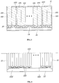
- FIG. 3 is a cross-sectional view of the battery module of FIG. 1 according to an exemplary embodiment of the present disclosure taken along line A-A'.
- a battery module may include: a module frame 11 having a top 111 and sides 112 and 113 that extend down from the top 111; a cell-stacking structure 100 disposed between both sides 112 and 113 of the module frame 11 and including a plurality of stacked battery cells 101; and a bottom plate 14 disposed under the cell-stacking structure 100 and bonded to the lower ends of the sides 112 and 113.
- the module frame 11 functions as a case that covers and encloses the top and two sides of the battery module and may include the top 111 (e.g., a top surface) and the sides 112 and 113 (e.g., a first side surface and a second side surface) that extend down from the top.
- the module frame 11 may have a rectangular parallelepiped shape with the front, rear, and bottom removed.
- the top 111 and the sides 112 and 113 of the module frame 11 may be formed integrally by extruding a metallic material such as aluminum.
- the cell-stacking structure 100 in which a plurality of battery cells 101 is stacked in parallel in surface contact with one another may be disposed between both sides 112 and 113 of the module frame 11.
- the cell-stacking structure 100 may be formed by stacking a plurality of cells 101 having a pouch shape in surface contact with one another.
- the battery cells 101 may each have a cell tap 102 that functions as an electrode thereof. Additionally, the battery cells 101 may be stacked in the cell-stacking structure 100 from a first side 112 to a second side 113 of the module frame 11, and the cell taps 102 of the battery cells 101 may be arranged to face the front portion and the rear portion of the module frame 11 (e.g., protrude toward 12 and 13).
- the cell-stacking structure 100 may include a surface pressure pad 103 capable of being compressed in the stacking direction between the stacked cells 101. The surface pressure pad 103 may attenuate and generate uniform the surface pressure acting between the stacked battery cells 101.
- the cell-stacking structure 100 may omit specific cartridges and the outermost cells 101 of the cell-stacking structure 100 may be in contact with the sides 112 and 113 of the module frame 11.
- the module frame 11 functions as a case of the battery module 10 and functions as a frame inside which the cell-stacking structure 100 is installed. Accordingly, specific cartridges may be omitted from the structure when stacking battery cell and thus, a battery module may be downsized.
- the bottom plate 14 may be disposed under the cell-stacking structure 100 after the cell-stacking structure 100 is disposed between the sides 112 and 113 of the module frame 11, and may be bonded to the sides 112 and 113 of the module frame 11 by welding or other bonding methods.
- the bottom plate 14 may be brought in contact with the cell-stacking structure 100 through a heat transfer substance 16.
- the heat transfer substance 16 may be provided to enable heat generated from the cell-stacking structure 100 including the battery cells 101 to transfer to the bottom plate 14.
- the heat transfer substance 16 may be a gap filler having excellent thermal conductivity. When the heat transfer substance 16 is liquid, it may be applied to the bottom of the cell-stacking structure 100 disposed between the sides 112 and 113 of the module frame 11 during the process of manufacturing the battery module. According to an exemplary embodiment of the present disclosure, since the bottom of the module frame 11 is open, the heat transfer substance 16 may be applied more easily. If necessary, the heat transfer substance 16 may be applied to the entire bottom, exposed through the open bottom, of the cell-stacking structure 100 or may be applied in various patterns such as a zigzag shape.
- the ability to transmit heat generated from the cell-stacking structure 100 to the bottom plate 14 may be improved by welding the bottom plate 14 to the lower ends of the sides 112 and 113 of the module frame 11 while pressing the bottom plate 14 toward the cell-stacking structure 100.
- the bottom plate 14 may be bonded to the lower ends of the sides 112 and 113 of the module frame 11 by welding or other bonding methods with the sides 112 and 113 of the module frame 11 pressed toward the cell-stacking structure 100.
- the performance of a battery module may be improved when a predetermined level of uniform surface pressure is maintained between battery cells stacked in the battery module.
- the lower ends of the sides 112 and 113 of the module frame 11 may be freely moved in some extent and thus, sufficient surface pressure may be applied between the battery cells 101 in the cell-stacking structure 100 by attaching the bottom plate 14 to the module frame 11 using welding or other bonding methods while pressing the sides 112 and 113 of the module frame 11 toward the cell-stacking structure, whereby it may be possible to improve the performance of the battery module.
- the battery module 10 may further include a cooling water block 15 attached to the bottom of the bottom plate 14.
- a cooling water pattern through which cooling water flows may be engraved (e.g., a groove passage may be formed) on the cooling water block 15 when seen from the bottom plate 14 and edges of the cooling block 15 may be bonded to the bottom of the bottom plate 14 and thus, cooling water flowing through the cooling water pattern may come in direct contact with the bottom plate 14.
- the heat generated from the cell-stacking structure 100 including the battery cells 101 may transfer to the cooling water flowing on the cooling water block 15 through the heat transfer substance 16 and the bottom plate 14.
- the battery module 10 has a shortened heat transfer path through which the heat transfers to the cooling water through the bottom plate 14 and the heat transfer substance 16 being in direct contact with the battery cells 101 that generates the heat, thus improving cooling performance. Additionally, by reducing the size and improving the cooling performance of the battery module 10, the battery module 10 may output greater or equal level of energy with a relatively small size in comparison to battery modules of the related art and thus, energy density may be improved.
- the battery module 10 may further include a front cover 12 and a rear cover 13 that are coupled to the front portion and the rear portion of the module frame 11.
- the inner sides of the front cover 12 and the rear cover 13 face the cell taps 102 on the battery cells 101 of the cell-stacking structure 100.
- the front cover 12 and the rear cover 13 may be made of an insulating material. The insulating material thus provides an overall insulating effect to the structure.
- FIG. 4 is a cross-sectional view of the battery module of FIG. 1 according to an exemplary embodiment of the present disclosure taken along line B-B'.
- the cell taps 101 included in the battery cells 101 may be bonded to one another to form electrical connection with the cell taps 102 of adjacent battery cells 101.
- cell taps may be bonded such that battery cells included in battery modules are connected in series, and thus, a pair of cell taps bonded to each other may be insulated from another adjacent pair of cell taps.
- the front cover 12 and the rear cover 13 may have separation walls 121 that extend between pair of cell taps bonded to each other on the surfaces facing the cell taps 102. Accordingly, even when pairs of bonded cell taps are bent or broken toward adjacent pairs of cell taps by a shock etc., insulation between the pairs of cell taps may be maintained by the separation walls 121 without a short with adjacent pairs of cell taps.
Landscapes
- Chemical & Material Sciences (AREA)
- Chemical Kinetics & Catalysis (AREA)
- Electrochemistry (AREA)
- General Chemical & Material Sciences (AREA)
- Engineering & Computer Science (AREA)
- Manufacturing & Machinery (AREA)
- Battery Mounting, Suspending (AREA)
- Secondary Cells (AREA)
Abstract
Description
- The present disclosure relates to a battery module, and more particularly, to a battery module having a simplified structure and high energy density.
- Batteries are generally mounted within vehicles to store electrical energy and a battery module outputs a predetermined voltage by connecting a plurality of battery cells, each of which outputs a unit voltage. A plurality of the battery modules are connected to output a desired voltage. Battery modules of the related art include cartridges for fixing battery cells. In other words, battery modules of the related art have a structure with cartridges between stacked battery cells. Additionally, the battery modules of the related art further include cooling fins disposed between battery cells in surface contact with the battery cells. The ends of the cooling fins indirectly discharge heat from the battery cells by coming into contact with a cooling block.
- As described above, since battery modules of the related art use cartridges, the size of the structure of stacked battery cells is increased. In particular, the module size is further increased by the cooling fins. Battery modules of the related art also use an indirect cooling method that discharges heat from battery cells using heat transfer through cooling fins disposed between the battery cells and thus, cooling efficiency is reduced.
- The description provided above as a related art of the present disclosure is merely for helping understanding the background of the present disclosure and should not be construed as being included in the related art known by those skilled in the art.
- The present disclosure provides a battery module that allows for simplifying and downsizing of a structure by reducing the number of parts and can achieve high energy density by securing an excellent heat dissipation ability.
- In accordance with an aspect of the present disclosure, a battery module may include: a module frame having a top and sides that extend down from the top; a cell-stacking structure disposed between the both sides of the module frame and including a plurality of stacked battery cells; and a bottom plate disposed under the cell-stacking structure and bonded to lower ends of the sides of the module frame.
- In an exemplary embodiment of the present disclosure, the battery cells may be stacked in surface contact with one another from a first side to a second side of the module frame. In addition, the cell-stacking structure may further include surface pressure pads disposed between some of the battery cells (e.g., a predetermined number of the battery cells) to be compressed in the stacking direction of the battery cells. The battery cells each may have electrode cell taps on both ends and may be stacked with the cell taps facing a front portion and a rear portion of the module frame.
- An exemplary embodiment of the present disclosure may further include a heat transfer substance disposed between the cell-stacking structure and the bottom plate. The heat transfer substance may be a gap filler of which thermal conductivity is increased by pressure and the bottom plate may be bonded to lower ends of the sides of the module frame while being pressed toward the cell-stacking structure. The bottom plate may be bonded to lower ends of the sides of the module frame with the sides of the module frame pressed toward the cell-stacking structure.
- An exemplary embodiment of the present disclosure may further include a cooling water block attached to the bottom of the bottom plate to supply cooling water to the bottom of the bottom plate. A front cover and a rear cover made of an insulating material may be respectively coupled to the front portion and the rear portion of the module frame. In particular, the front cover and the rear cover each may have separation walls that extend between pairs of bonded cell taps on surfaces facing the cell taps.
- According to the battery module, since a module frame has a structure with a top and sides that extend from both ends of the top and battery cells are stacked with sides facing one another, specific cartridges for stacking the battery cell may be omitted and thus, the module may be downsized. Further, since the bottom of the module frame is open, it may be possible to more easily apply a heat transfer substance to the bottom of the cell-stacking structure after disposing the cell-stacking structure having the stacked battery cells between both sides of the module frame. According to the battery module, since a bottom plate may be bonded to the module frame while being pressed toward the cell-stacking structure after the heat transfer substance is applied, when a heat transfer substance of which thermal conductivity is increased as pressure is increased is used, a heat transfer effect may be considerably improved.
- As described above, according to the battery module, cooling performance may be improved by reducing the size and the heat transfer ability of the battery module may be improved. Therefore, high energy density of the battery module may be achieved. Further, according to the battery module, by bonding the bottom plate to the module frame while pressing both sides of the module frame toward the cell-stacking structure after disposing the cell-stacking structure between both sides of the module frame, the battery module may be manufactured with a predetermined level of surface pressure between the battery cells and thus, the initial performance of the battery module may be improved.
- The effects of the present disclosure are not limited to the effects described above and other effects may be clearly understood by those skilled in the art from the following description.
- The above and other aspects, features and advantages of the present disclosure will be more apparent from the following detailed description taken in conjunction with the accompanying drawings, in which:
-
FIG. 1 is a perspective view of a battery module according to an exemplary embodiment of the present disclosure; -
FIG. 2 is a detailed view of the battery module according to an exemplary embodiment of the present disclosure shown inFIG. 1 ; -
FIG. 3 is a cross-sectional view of the battery module ofFIG. 1 according to an exemplary embodiment of the present disclosure taken along line A-A'; and -
FIG. 4 is a cross-sectional view of the battery module ofFIG. 1 according to an exemplary embodiment of the present disclosure taken along line B-B'. - It is understood that the term "vehicle" or "vehicular" or other similar term as used herein is inclusive of motor vehicles in general such as passenger automobiles including sports utility vehicles (SUV), buses, trucks, various commercial vehicles, watercraft including a variety of boats and ships, aircraft, and the like, and includes hybrid vehicles, electric vehicles, plug-in hybrid electric vehicles, hydrogen-powered vehicles and other alternative fuel vehicles (e.g. fuels derived from resources other than petroleum). As referred to herein, a hybrid vehicle is a vehicle that has two or more sources of power, for example both gasoline-powered and electric-powered vehicles.
- The terminology used herein is for the purpose of describing particular embodiments only and is not intended to be limiting of the disclosure. As used herein, the singular forms "a", "an" and "the" are intended to include the plural forms as well, unless the context clearly indicates otherwise. It will be further understood that the terms "comprises" and/or "comprising," when used in this specification, specify the presence of stated features, integers, steps, operations, elements, and/or components, but do not preclude the presence or addition of one or more other features, integers, steps, operations, elements, components, and/or groups thereof. As used herein, the term "and/or" includes any and all combinations of one or more of the associated listed items.
- A battery module according to various exemplary embodiments of the present disclosure is described hereafter in detail with reference to the accompanying drawings.
-
FIG. 1 is a perspective view of a battery module according to an exemplary embodiment of the present disclosure,FIG. 2 is a detailed view of the battery module according to an exemplary embodiment of the present disclosure shown inFIG. 1 , andFIG. 3 is a cross-sectional view of the battery module ofFIG. 1 according to an exemplary embodiment of the present disclosure taken along line A-A'. - Referring to
FIGS. 1 to 3 , a battery module according to an exemplary embodiment of the present disclosure may include: amodule frame 11 having atop 111 andsides top 111; a cell-stacking structure 100 disposed between bothsides module frame 11 and including a plurality of stackedbattery cells 101; and abottom plate 14 disposed under the cell-stacking structure 100 and bonded to the lower ends of thesides - The
module frame 11 functions as a case that covers and encloses the top and two sides of the battery module and may include the top 111 (e.g., a top surface) and thesides 112 and 113 (e.g., a first side surface and a second side surface) that extend down from the top. In other words, themodule frame 11 may have a rectangular parallelepiped shape with the front, rear, and bottom removed. Thetop 111 and thesides module frame 11 may be formed integrally by extruding a metallic material such as aluminum. The cell-stacking structure 100 in which a plurality ofbattery cells 101 is stacked in parallel in surface contact with one another may be disposed between bothsides module frame 11. - The cell-
stacking structure 100 may be formed by stacking a plurality ofcells 101 having a pouch shape in surface contact with one another. Thebattery cells 101 may each have acell tap 102 that functions as an electrode thereof. Additionally, thebattery cells 101 may be stacked in the cell-stacking structure 100 from afirst side 112 to asecond side 113 of themodule frame 11, and thecell taps 102 of thebattery cells 101 may be arranged to face the front portion and the rear portion of the module frame 11 (e.g., protrude toward 12 and 13). The cell-stacking structure 100 may include asurface pressure pad 103 capable of being compressed in the stacking direction between thestacked cells 101. Thesurface pressure pad 103 may attenuate and generate uniform the surface pressure acting between the stackedbattery cells 101. - In an exemplary embodiment of the present disclosure, the cell-
stacking structure 100 may omit specific cartridges and theoutermost cells 101 of the cell-stacking structure 100 may be in contact with thesides module frame 11. In other words, in an exemplary embodiment of the present disclosure, themodule frame 11 functions as a case of thebattery module 10 and functions as a frame inside which the cell-stacking structure 100 is installed. Accordingly, specific cartridges may be omitted from the structure when stacking battery cell and thus, a battery module may be downsized. - Further, the
bottom plate 14 may be disposed under the cell-stacking structure 100 after the cell-stacking structure 100 is disposed between thesides module frame 11, and may be bonded to thesides module frame 11 by welding or other bonding methods. In particular, thebottom plate 14 may be brought in contact with the cell-stacking structure 100 through aheat transfer substance 16. Theheat transfer substance 16 may be provided to enable heat generated from the cell-stacking structure 100 including thebattery cells 101 to transfer to thebottom plate 14. - The
heat transfer substance 16 may be a gap filler having excellent thermal conductivity. When theheat transfer substance 16 is liquid, it may be applied to the bottom of the cell-stackingstructure 100 disposed between thesides module frame 11 during the process of manufacturing the battery module. According to an exemplary embodiment of the present disclosure, since the bottom of themodule frame 11 is open, theheat transfer substance 16 may be applied more easily. If necessary, theheat transfer substance 16 may be applied to the entire bottom, exposed through the open bottom, of the cell-stackingstructure 100 or may be applied in various patterns such as a zigzag shape. - In particular, in an exemplary embodiment of the present disclosure, when a gap filler of which the thermal conductivity is increased, as pressure is increased, is used as the
heat transfer substance 16, the ability to transmit heat generated from the cell-stackingstructure 100 to thebottom plate 14 may be improved by welding thebottom plate 14 to the lower ends of thesides module frame 11 while pressing thebottom plate 14 toward the cell-stackingstructure 100. - The
bottom plate 14 may be bonded to the lower ends of thesides module frame 11 by welding or other bonding methods with thesides module frame 11 pressed toward the cell-stackingstructure 100. The performance of a battery module may be improved when a predetermined level of uniform surface pressure is maintained between battery cells stacked in the battery module. In addition, the lower ends of thesides module frame 11 may be freely moved in some extent and thus, sufficient surface pressure may be applied between thebattery cells 101 in the cell-stackingstructure 100 by attaching thebottom plate 14 to themodule frame 11 using welding or other bonding methods while pressing thesides module frame 11 toward the cell-stacking structure, whereby it may be possible to improve the performance of the battery module. - The
battery module 10 according to an exemplary embodiment of the present disclosure may further include a coolingwater block 15 attached to the bottom of thebottom plate 14. In particular, a cooling water pattern through which cooling water flows may be engraved (e.g., a groove passage may be formed) on the coolingwater block 15 when seen from thebottom plate 14 and edges of thecooling block 15 may be bonded to the bottom of thebottom plate 14 and thus, cooling water flowing through the cooling water pattern may come in direct contact with thebottom plate 14. According to this structure, the heat generated from the cell-stackingstructure 100 including thebattery cells 101 may transfer to the cooling water flowing on the coolingwater block 15 through theheat transfer substance 16 and thebottom plate 14. - As described above, the
battery module 10 according to an exemplary embodiment of the present disclosure has a shortened heat transfer path through which the heat transfers to the cooling water through thebottom plate 14 and theheat transfer substance 16 being in direct contact with thebattery cells 101 that generates the heat, thus improving cooling performance. Additionally, by reducing the size and improving the cooling performance of thebattery module 10, thebattery module 10 may output greater or equal level of energy with a relatively small size in comparison to battery modules of the related art and thus, energy density may be improved. - The
battery module 10 according to an exemplary embodiment of the present disclosure may further include afront cover 12 and arear cover 13 that are coupled to the front portion and the rear portion of themodule frame 11. The inner sides of thefront cover 12 and therear cover 13 face the cell taps 102 on thebattery cells 101 of the cell-stackingstructure 100. In an exemplary embodiment of the present disclosure, thefront cover 12 and therear cover 13 may be made of an insulating material. The insulating material thus provides an overall insulating effect to the structure. -
FIG. 4 is a cross-sectional view of the battery module ofFIG. 1 according to an exemplary embodiment of the present disclosure taken along line B-B'. Referring toFIG. 4 , the cell taps 101 included in thebattery cells 101 may be bonded to one another to form electrical connection with the cell taps 102 ofadjacent battery cells 101. In general, cell taps may be bonded such that battery cells included in battery modules are connected in series, and thus, a pair of cell taps bonded to each other may be insulated from another adjacent pair of cell taps. - In an exemplary embodiment of the present disclosure, the
front cover 12 and therear cover 13 may haveseparation walls 121 that extend between pair of cell taps bonded to each other on the surfaces facing the cell taps 102. Accordingly, even when pairs of bonded cell taps are bent or broken toward adjacent pairs of cell taps by a shock etc., insulation between the pairs of cell taps may be maintained by theseparation walls 121 without a short with adjacent pairs of cell taps. - Although the present disclosure was provided above in relation to specific exemplary embodiments shown in the drawings, it is apparent to those skilled in the art that the present disclosure may be changed and modified in various ways without departing from the scope of the present disclosure, which is described in the following claims.
Claims (10)
- A battery module, comprising:a module frame having a top and sides that extend down from the top;a cell-stacking structure disposed between the sides of the module frame and including a plurality of stacked battery cells; anda bottom plate disposed under the cell-stacking structure and bonded to lower ends of the sides of the module frame.
- The battery module of claim 1, wherein the sides of the module frame include a first side and a second side and the battery cells are stacked in surface contact with one another from the first side to the second side of the module frame.
- The battery module of claim 1 or 2, wherein the cell-stacking structure further includes:
surface pressure pads disposed between a predetermined number of the battery cells to be compressed in the stacking direction of the battery cells. - The battery module of any one of claims 1 to 3, wherein the battery cells each include electrode cell taps on both ends thereof and the battery cells are stacked with the cell taps facing a front portion and a rear portion of the module frame.
- The battery module of any one of claims 1 to 4, further comprising:
a heat transfer substance disposed between the cell-stacking structure and the bottom plate. - The battery module of claim 5, wherein the heat transfer substance is a gap filler of which thermal conductivity is increased by pressure and the bottom plate is bonded to lower ends of the sides of the module frame while being pressed toward the cell-stacking structure.
- The battery module of any one of claims 1 to 6, wherein the bottom plate is bonded to lower ends of the sides of the module frame with the sides of the module frame pressed toward the cell-stacking structure.
- The battery module of any one of claims 1 to 7, further comprising:
a cooling water block attached to the bottom of the bottom plate to supply cooling water to the bottom of the bottom plate. - The battery module of any one of claims 4 to 8, further comprising:a front cover and a rear cover made of an insulating material and respectively coupled to the front portion and the rear portion of the module frame,wherein the front cover and the rear cover each have separation walls that extend between pairs of bonded cell taps on surfaces facing the cell taps.
- The battery module of claim 8 or 9, further comprising:
a cooling water pattern engraved on the cooling water block and through which cooling water flows.
Applications Claiming Priority (1)
| Application Number | Priority Date | Filing Date | Title |
|---|---|---|---|
| KR1020180138388A KR102691475B1 (en) | 2018-11-12 | 2018-11-12 | Battery module |
Publications (2)
| Publication Number | Publication Date |
|---|---|
| EP3651232A1 true EP3651232A1 (en) | 2020-05-13 |
| EP3651232B1 EP3651232B1 (en) | 2025-03-26 |
Family
ID=66290282
Family Applications (1)
| Application Number | Title | Priority Date | Filing Date |
|---|---|---|---|
| EP19171322.1A Active EP3651232B1 (en) | 2018-11-12 | 2019-04-26 | Battery module |
Country Status (4)
| Country | Link |
|---|---|
| US (1) | US11245151B2 (en) |
| EP (1) | EP3651232B1 (en) |
| KR (1) | KR102691475B1 (en) |
| CN (1) | CN111180621A (en) |
Cited By (2)
| Publication number | Priority date | Publication date | Assignee | Title |
|---|---|---|---|---|
| EP3989348A1 (en) * | 2020-10-20 | 2022-04-27 | Hyundai Motor Company | Battery module and battery pack including same |
| WO2023288029A1 (en) * | 2021-07-14 | 2023-01-19 | Our Next Energy, Inc. | Structural cell to pack battery |
Families Citing this family (12)
| Publication number | Priority date | Publication date | Assignee | Title |
|---|---|---|---|---|
| KR102829343B1 (en) * | 2019-07-24 | 2025-07-02 | 현대자동차주식회사 | Apparatus for cooling battery of vehicle and manufacturing method of the same |
| KR102885971B1 (en) * | 2020-04-22 | 2025-11-12 | 주식회사 엘지에너지솔루션 | Battery module and battery pack including the same |
| KR102800478B1 (en) | 2020-08-05 | 2025-04-23 | 주식회사 엘지에너지솔루션 | Battery module, battery pack including the same and method of manufacturing battery module |
| KR102929045B1 (en) * | 2020-08-07 | 2026-02-19 | 주식회사 엘지에너지솔루션 | Battery module and battery pack including the same |
| KR102937131B1 (en) * | 2020-08-14 | 2026-03-09 | 주식회사 엘지에너지솔루션 | Battery module and battery pack including the same |
| KR102897044B1 (en) * | 2020-08-20 | 2025-12-08 | 에스케이온 주식회사 | Battery module |
| KR102876300B1 (en) * | 2020-08-24 | 2025-10-23 | 주식회사 엘지에너지솔루션 | Battery module and battery pack including the same |
| KR102955871B1 (en) * | 2020-11-23 | 2026-04-21 | 주식회사 엘지에너지솔루션 | Battery module, battery pack comprising the battery module and vehicle comprising the battery pack |
| KR102951435B1 (en) * | 2021-05-20 | 2026-04-09 | 주식회사 엘지에너지솔루션 | Battery module and battery pack comprising the battery module |
| KR102402503B1 (en) | 2022-02-17 | 2022-05-26 | 주식회사 서연이화 | A battery pack cooling structure |
| US20250141003A1 (en) * | 2022-05-26 | 2025-05-01 | Lg Energy Solution, Ltd. | Battery module and method for manufacturing the same |
| KR20240084820A (en) * | 2022-12-07 | 2024-06-14 | 현대자동차주식회사 | Battery pack case |
Citations (4)
| Publication number | Priority date | Publication date | Assignee | Title |
|---|---|---|---|---|
| DE102005031504A1 (en) * | 2005-07-06 | 2007-01-11 | Daimlerchrysler Ag | Prismatic battery of several single cells |
| EP2523249A2 (en) * | 2010-01-06 | 2012-11-14 | LG Chem, Ltd. | Mid- or large-sized battery pack having improved cooling efficiency |
| WO2018008866A1 (en) * | 2016-07-06 | 2018-01-11 | 주식회사 엘지화학 | Battery module, battery pack comprising same, and vehicle |
| EP3343691A1 (en) * | 2015-09-24 | 2018-07-04 | LG Chem, Ltd. | Battery module |
Family Cites Families (12)
| Publication number | Priority date | Publication date | Assignee | Title |
|---|---|---|---|---|
| US7875378B2 (en) * | 2006-03-06 | 2011-01-25 | Lg Chem, Ltd. | Voltage sensing member and battery module employed with the same |
| US9450276B2 (en) * | 2011-04-19 | 2016-09-20 | A123 Systems Llc | Thermal gap pad for a prismatic battery pack |
| AT513127B1 (en) * | 2012-08-21 | 2014-02-15 | Avl List Gmbh | Electric energy storage |
| US20150037662A1 (en) * | 2013-07-30 | 2015-02-05 | Johnson Controls Technology Company | System and method for sealing a battery cell |
| DE102013222293A1 (en) * | 2013-11-04 | 2015-05-07 | Robert Bosch Gmbh | battery module |
| CN112531255B (en) | 2015-02-27 | 2023-07-07 | 株式会社Lg新能源 | battery module |
| CN104993183B (en) * | 2015-05-22 | 2017-10-03 | 江苏科技大学 | A kind of battery module, battery modules and battery modules method for packing |
| KR20180036863A (en) | 2016-09-30 | 2018-04-10 | 현대자동차주식회사 | Battery unit |
| KR20180068379A (en) | 2016-12-13 | 2018-06-22 | 현대자동차주식회사 | Battery case of electric vehicle |
| KR20190043277A (en) | 2017-10-18 | 2019-04-26 | 현대자동차주식회사 | Battery module having cooling channel and battery system comprising the same |
| KR102603060B1 (en) | 2018-06-08 | 2023-11-16 | 현대자동차주식회사 | Cooling device for battery of vehicle and mafufacturing method of the same |
| KR20200001692A (en) | 2018-06-28 | 2020-01-07 | 현대자동차주식회사 | Battery module for vehicle |
-
2018
- 2018-11-12 KR KR1020180138388A patent/KR102691475B1/en active Active
-
2019
- 2019-04-26 EP EP19171322.1A patent/EP3651232B1/en active Active
- 2019-05-01 US US16/400,813 patent/US11245151B2/en active Active
- 2019-05-22 CN CN201910428085.6A patent/CN111180621A/en active Pending
Patent Citations (4)
| Publication number | Priority date | Publication date | Assignee | Title |
|---|---|---|---|---|
| DE102005031504A1 (en) * | 2005-07-06 | 2007-01-11 | Daimlerchrysler Ag | Prismatic battery of several single cells |
| EP2523249A2 (en) * | 2010-01-06 | 2012-11-14 | LG Chem, Ltd. | Mid- or large-sized battery pack having improved cooling efficiency |
| EP3343691A1 (en) * | 2015-09-24 | 2018-07-04 | LG Chem, Ltd. | Battery module |
| WO2018008866A1 (en) * | 2016-07-06 | 2018-01-11 | 주식회사 엘지화학 | Battery module, battery pack comprising same, and vehicle |
Cited By (3)
| Publication number | Priority date | Publication date | Assignee | Title |
|---|---|---|---|---|
| EP3989348A1 (en) * | 2020-10-20 | 2022-04-27 | Hyundai Motor Company | Battery module and battery pack including same |
| US12009536B2 (en) | 2020-10-20 | 2024-06-11 | Hyundai Motor Company | Battery module and battery pack including same |
| WO2023288029A1 (en) * | 2021-07-14 | 2023-01-19 | Our Next Energy, Inc. | Structural cell to pack battery |
Also Published As
| Publication number | Publication date |
|---|---|
| EP3651232B1 (en) | 2025-03-26 |
| KR20200055215A (en) | 2020-05-21 |
| KR102691475B1 (en) | 2024-08-02 |
| US11245151B2 (en) | 2022-02-08 |
| CN111180621A (en) | 2020-05-19 |
| US20200152931A1 (en) | 2020-05-14 |
Similar Documents
| Publication | Publication Date | Title |
|---|---|---|
| US11245151B2 (en) | Battery module | |
| KR101833526B1 (en) | Battery Module Having Water-Cooled Type Cooling Structure | |
| CN107946689B (en) | Battery system with external thermal management system | |
| EP2763214B1 (en) | Battery module | |
| CN102498610B (en) | Including novel structural heat dissipation components, battery modules and medium and large battery packs | |
| KR101990590B1 (en) | Battery module, battery pack comprising the battery module and vehicle comprising the battery pack | |
| KR101218751B1 (en) | Middle or Large-sized Battery Pack of Improved Cooling Efficiency | |
| KR101326086B1 (en) | Battery Module with Compact Structure and Excellent Heat Radiation Characteristics and Middle or Large-sized Battery Pack Employed with the Same | |
| EP3611776A1 (en) | Battery module | |
| KR101252944B1 (en) | Battery pack with enhanced radiating ability | |
| KR102073950B1 (en) | Battery Pack Having Edge Cooling-Typed Member | |
| US20180191041A1 (en) | Water-cooled battery module of electric vehicle | |
| CN219226522U (en) | Battery and electricity utilization device | |
| US20250023199A1 (en) | Battery, electrical apparatus and battery forming method | |
| KR101615928B1 (en) | Middle or Large-sized Battery Pack Having Efficient Cooling Structure | |
| CN101772857A (en) | Battery, particularly for a hybrid drive | |
| CN110380112B (en) | Battery module, assembling method and power battery | |
| CN210040347U (en) | Battery module and power battery | |
| KR101543477B1 (en) | Battery module and lithium secondary battery pack comprising the same | |
| KR20200104620A (en) | Battery module having all-around heat transfer path | |
| CN210040348U (en) | Battery module and power battery | |
| CN209447888U (en) | The protection mounting device of 48V lithium-ion battery systems | |
| CN119497931A (en) | Battery module and battery pack containing the battery module | |
| KR101262033B1 (en) | Cooling Member Having Improved Reliability to Cooling Design and Battery Module Employed with the Same | |
| CN120895794A (en) | Battery devices and electrical appliances |
Legal Events
| Date | Code | Title | Description |
|---|---|---|---|
| PUAI | Public reference made under article 153(3) epc to a published international application that has entered the european phase |
Free format text: ORIGINAL CODE: 0009012 |
|
| STAA | Information on the status of an ep patent application or granted ep patent |
Free format text: STATUS: THE APPLICATION HAS BEEN PUBLISHED |
|
| AK | Designated contracting states |
Kind code of ref document: A1 Designated state(s): AL AT BE BG CH CY CZ DE DK EE ES FI FR GB GR HR HU IE IS IT LI LT LU LV MC MK MT NL NO PL PT RO RS SE SI SK SM TR |
|
| AX | Request for extension of the european patent |
Extension state: BA ME |
|
| STAA | Information on the status of an ep patent application or granted ep patent |
Free format text: STATUS: REQUEST FOR EXAMINATION WAS MADE |
|
| 17P | Request for examination filed |
Effective date: 20201103 |
|
| RBV | Designated contracting states (corrected) |
Designated state(s): AL AT BE BG CH CY CZ DE DK EE ES FI FR GB GR HR HU IE IS IT LI LT LU LV MC MK MT NL NO PL PT RO RS SE SI SK SM TR |
|
| RAP3 | Party data changed (applicant data changed or rights of an application transferred) |
Owner name: HYUNDAI MOTOR COMPANY Owner name: KIA CORPORATION |
|
| P01 | Opt-out of the competence of the unified patent court (upc) registered |
Effective date: 20230505 |
|
| REG | Reference to a national code |
Ref country code: DE Ref legal event code: R079 Free format text: PREVIOUS MAIN CLASS: H01M0002100000 Ipc: H01M0050211000 Ref country code: DE Ref legal event code: R079 Ref document number: 602019067678 Country of ref document: DE Free format text: PREVIOUS MAIN CLASS: H01M0002100000 Ipc: H01M0050211000 |
|
| STAA | Information on the status of an ep patent application or granted ep patent |
Free format text: STATUS: EXAMINATION IS IN PROGRESS |
|
| 17Q | First examination report despatched |
Effective date: 20240102 |
|
| RIC1 | Information provided on ipc code assigned before grant |
Ipc: H01M 10/6554 20140101ALI20231219BHEP Ipc: H01M 10/647 20140101ALI20231219BHEP Ipc: H01M 10/613 20140101ALI20231219BHEP Ipc: H01M 10/04 20060101ALI20231219BHEP Ipc: H01M 50/291 20210101ALI20231219BHEP Ipc: H01M 50/233 20210101ALI20231219BHEP Ipc: H01M 50/211 20210101AFI20231219BHEP |
|
| GRAP | Despatch of communication of intention to grant a patent |
Free format text: ORIGINAL CODE: EPIDOSNIGR1 |
|
| STAA | Information on the status of an ep patent application or granted ep patent |
Free format text: STATUS: GRANT OF PATENT IS INTENDED |
|
| INTG | Intention to grant announced |
Effective date: 20241015 |
|
| GRAS | Grant fee paid |
Free format text: ORIGINAL CODE: EPIDOSNIGR3 |
|
| GRAA | (expected) grant |
Free format text: ORIGINAL CODE: 0009210 |
|
| STAA | Information on the status of an ep patent application or granted ep patent |
Free format text: STATUS: THE PATENT HAS BEEN GRANTED |
|
| AK | Designated contracting states |
Kind code of ref document: B1 Designated state(s): AL AT BE BG CH CY CZ DE DK EE ES FI FR GB GR HR HU IE IS IT LI LT LU LV MC MK MT NL NO PL PT RO RS SE SI SK SM TR |
|
| REG | Reference to a national code |
Ref country code: GB Ref legal event code: FG4D |
|
| REG | Reference to a national code |
Ref country code: CH Ref legal event code: EP |
|
| REG | Reference to a national code |
Ref country code: DE Ref legal event code: R096 Ref document number: 602019067678 Country of ref document: DE |
|
| REG | Reference to a national code |
Ref country code: IE Ref legal event code: FG4D |
|
| PG25 | Lapsed in a contracting state [announced via postgrant information from national office to epo] |
Ref country code: RS Free format text: LAPSE BECAUSE OF FAILURE TO SUBMIT A TRANSLATION OF THE DESCRIPTION OR TO PAY THE FEE WITHIN THE PRESCRIBED TIME-LIMIT Effective date: 20250626 |
|
| PG25 | Lapsed in a contracting state [announced via postgrant information from national office to epo] |
Ref country code: FI Free format text: LAPSE BECAUSE OF FAILURE TO SUBMIT A TRANSLATION OF THE DESCRIPTION OR TO PAY THE FEE WITHIN THE PRESCRIBED TIME-LIMIT Effective date: 20250326 |
|
| REG | Reference to a national code |
Ref country code: LT Ref legal event code: MG9D |
|
| PG25 | Lapsed in a contracting state [announced via postgrant information from national office to epo] |
Ref country code: NO Free format text: LAPSE BECAUSE OF FAILURE TO SUBMIT A TRANSLATION OF THE DESCRIPTION OR TO PAY THE FEE WITHIN THE PRESCRIBED TIME-LIMIT Effective date: 20250626 |
|
| PG25 | Lapsed in a contracting state [announced via postgrant information from national office to epo] |
Ref country code: HR Free format text: LAPSE BECAUSE OF FAILURE TO SUBMIT A TRANSLATION OF THE DESCRIPTION OR TO PAY THE FEE WITHIN THE PRESCRIBED TIME-LIMIT Effective date: 20250326 |
|
| PG25 | Lapsed in a contracting state [announced via postgrant information from national office to epo] |
Ref country code: LV Free format text: LAPSE BECAUSE OF FAILURE TO SUBMIT A TRANSLATION OF THE DESCRIPTION OR TO PAY THE FEE WITHIN THE PRESCRIBED TIME-LIMIT Effective date: 20250326 |
|
| PG25 | Lapsed in a contracting state [announced via postgrant information from national office to epo] |
Ref country code: GR Free format text: LAPSE BECAUSE OF FAILURE TO SUBMIT A TRANSLATION OF THE DESCRIPTION OR TO PAY THE FEE WITHIN THE PRESCRIBED TIME-LIMIT Effective date: 20250627 Ref country code: BG Free format text: LAPSE BECAUSE OF FAILURE TO SUBMIT A TRANSLATION OF THE DESCRIPTION OR TO PAY THE FEE WITHIN THE PRESCRIBED TIME-LIMIT Effective date: 20250326 |
|
| REG | Reference to a national code |
Ref country code: NL Ref legal event code: MP Effective date: 20250326 |
|
| PG25 | Lapsed in a contracting state [announced via postgrant information from national office to epo] |
Ref country code: NL Free format text: LAPSE BECAUSE OF FAILURE TO SUBMIT A TRANSLATION OF THE DESCRIPTION OR TO PAY THE FEE WITHIN THE PRESCRIBED TIME-LIMIT Effective date: 20250326 |
|
| PG25 | Lapsed in a contracting state [announced via postgrant information from national office to epo] |
Ref country code: SE Free format text: LAPSE BECAUSE OF FAILURE TO SUBMIT A TRANSLATION OF THE DESCRIPTION OR TO PAY THE FEE WITHIN THE PRESCRIBED TIME-LIMIT Effective date: 20250326 |
|
| REG | Reference to a national code |
Ref country code: AT Ref legal event code: MK05 Ref document number: 1779882 Country of ref document: AT Kind code of ref document: T Effective date: 20250326 |
|
| PG25 | Lapsed in a contracting state [announced via postgrant information from national office to epo] |
Ref country code: SM Free format text: LAPSE BECAUSE OF FAILURE TO SUBMIT A TRANSLATION OF THE DESCRIPTION OR TO PAY THE FEE WITHIN THE PRESCRIBED TIME-LIMIT Effective date: 20250326 |
|
| PG25 | Lapsed in a contracting state [announced via postgrant information from national office to epo] |
Ref country code: ES Free format text: LAPSE BECAUSE OF FAILURE TO SUBMIT A TRANSLATION OF THE DESCRIPTION OR TO PAY THE FEE WITHIN THE PRESCRIBED TIME-LIMIT Effective date: 20250326 Ref country code: PT Free format text: LAPSE BECAUSE OF FAILURE TO SUBMIT A TRANSLATION OF THE DESCRIPTION OR TO PAY THE FEE WITHIN THE PRESCRIBED TIME-LIMIT Effective date: 20250728 |
|
| PG25 | Lapsed in a contracting state [announced via postgrant information from national office to epo] |
Ref country code: PL Free format text: LAPSE BECAUSE OF FAILURE TO SUBMIT A TRANSLATION OF THE DESCRIPTION OR TO PAY THE FEE WITHIN THE PRESCRIBED TIME-LIMIT Effective date: 20250326 Ref country code: IT Free format text: LAPSE BECAUSE OF FAILURE TO SUBMIT A TRANSLATION OF THE DESCRIPTION OR TO PAY THE FEE WITHIN THE PRESCRIBED TIME-LIMIT Effective date: 20250326 |
|
| PG25 | Lapsed in a contracting state [announced via postgrant information from national office to epo] |
Ref country code: AT Free format text: LAPSE BECAUSE OF FAILURE TO SUBMIT A TRANSLATION OF THE DESCRIPTION OR TO PAY THE FEE WITHIN THE PRESCRIBED TIME-LIMIT Effective date: 20250326 |
|
| PG25 | Lapsed in a contracting state [announced via postgrant information from national office to epo] |
Ref country code: EE Free format text: LAPSE BECAUSE OF FAILURE TO SUBMIT A TRANSLATION OF THE DESCRIPTION OR TO PAY THE FEE WITHIN THE PRESCRIBED TIME-LIMIT Effective date: 20250326 |
|
| PG25 | Lapsed in a contracting state [announced via postgrant information from national office to epo] |
Ref country code: RO Free format text: LAPSE BECAUSE OF FAILURE TO SUBMIT A TRANSLATION OF THE DESCRIPTION OR TO PAY THE FEE WITHIN THE PRESCRIBED TIME-LIMIT Effective date: 20250326 |
|
| PG25 | Lapsed in a contracting state [announced via postgrant information from national office to epo] |
Ref country code: SK Free format text: LAPSE BECAUSE OF FAILURE TO SUBMIT A TRANSLATION OF THE DESCRIPTION OR TO PAY THE FEE WITHIN THE PRESCRIBED TIME-LIMIT Effective date: 20250326 |
|
| PG25 | Lapsed in a contracting state [announced via postgrant information from national office to epo] |
Ref country code: IS Free format text: LAPSE BECAUSE OF FAILURE TO SUBMIT A TRANSLATION OF THE DESCRIPTION OR TO PAY THE FEE WITHIN THE PRESCRIBED TIME-LIMIT Effective date: 20250726 |
|
| REG | Reference to a national code |
Ref country code: CH Ref legal event code: H13 Free format text: ST27 STATUS EVENT CODE: U-0-0-H10-H13 (AS PROVIDED BY THE NATIONAL OFFICE) Effective date: 20251125 |
|
| PG25 | Lapsed in a contracting state [announced via postgrant information from national office to epo] |
Ref country code: LU Free format text: LAPSE BECAUSE OF NON-PAYMENT OF DUE FEES Effective date: 20250426 |
|
| PG25 | Lapsed in a contracting state [announced via postgrant information from national office to epo] |
Ref country code: MC Free format text: LAPSE BECAUSE OF FAILURE TO SUBMIT A TRANSLATION OF THE DESCRIPTION OR TO PAY THE FEE WITHIN THE PRESCRIBED TIME-LIMIT Effective date: 20250326 |
|
| REG | Reference to a national code |
Ref country code: BE Ref legal event code: MM Effective date: 20250430 |
|
| REG | Reference to a national code |
Ref country code: DE Ref legal event code: R097 Ref document number: 602019067678 Country of ref document: DE |
|
| PG25 | Lapsed in a contracting state [announced via postgrant information from national office to epo] |
Ref country code: DK Free format text: LAPSE BECAUSE OF FAILURE TO SUBMIT A TRANSLATION OF THE DESCRIPTION OR TO PAY THE FEE WITHIN THE PRESCRIBED TIME-LIMIT Effective date: 20250326 |
|
| PG25 | Lapsed in a contracting state [announced via postgrant information from national office to epo] |
Ref country code: BE Free format text: LAPSE BECAUSE OF NON-PAYMENT OF DUE FEES Effective date: 20250430 |
|
| PG25 | Lapsed in a contracting state [announced via postgrant information from national office to epo] |
Ref country code: CH Free format text: LAPSE BECAUSE OF NON-PAYMENT OF DUE FEES Effective date: 20250430 |
|
| PG25 | Lapsed in a contracting state [announced via postgrant information from national office to epo] |
Ref country code: CZ Free format text: LAPSE BECAUSE OF FAILURE TO SUBMIT A TRANSLATION OF THE DESCRIPTION OR TO PAY THE FEE WITHIN THE PRESCRIBED TIME-LIMIT Effective date: 20250326 |
|
| PLBE | No opposition filed within time limit |
Free format text: ORIGINAL CODE: 0009261 |
|
| STAA | Information on the status of an ep patent application or granted ep patent |
Free format text: STATUS: NO OPPOSITION FILED WITHIN TIME LIMIT |
|
| REG | Reference to a national code |
Ref country code: CH Ref legal event code: L10 Free format text: ST27 STATUS EVENT CODE: U-0-0-L10-L00 (AS PROVIDED BY THE NATIONAL OFFICE) Effective date: 20260211 |
|
| 26N | No opposition filed |
Effective date: 20260105 |
|
| PGFP | Annual fee paid to national office [announced via postgrant information from national office to epo] |
Ref country code: GB Payment date: 20260324 Year of fee payment: 8 |
|
| PG25 | Lapsed in a contracting state [announced via postgrant information from national office to epo] |
Ref country code: IE Free format text: LAPSE BECAUSE OF NON-PAYMENT OF DUE FEES Effective date: 20250426 |
|
| PGFP | Annual fee paid to national office [announced via postgrant information from national office to epo] |
Ref country code: FR Payment date: 20260323 Year of fee payment: 8 |
|
| PG25 | Lapsed in a contracting state [announced via postgrant information from national office to epo] |
Ref country code: CY Free format text: LAPSE BECAUSE OF FAILURE TO SUBMIT A TRANSLATION OF THE DESCRIPTION OR TO PAY THE FEE WITHIN THE PRESCRIBED TIME-LIMIT Effective date: 20250326 |
|
| PG25 | Lapsed in a contracting state [announced via postgrant information from national office to epo] |
Ref country code: LT Free format text: LAPSE BECAUSE OF FAILURE TO SUBMIT A TRANSLATION OF THE DESCRIPTION OR TO PAY THE FEE WITHIN THE PRESCRIBED TIME-LIMIT Effective date: 20250326 |
|
| PGFP | Annual fee paid to national office [announced via postgrant information from national office to epo] |
Ref country code: DE Payment date: 20260323 Year of fee payment: 8 |