EP3651218A1 - Thermoelectric conversion element and thermoelectric conversion device - Google Patents
Thermoelectric conversion element and thermoelectric conversion device Download PDFInfo
- Publication number
- EP3651218A1 EP3651218A1 EP18827510.1A EP18827510A EP3651218A1 EP 3651218 A1 EP3651218 A1 EP 3651218A1 EP 18827510 A EP18827510 A EP 18827510A EP 3651218 A1 EP3651218 A1 EP 3651218A1
- Authority
- EP
- European Patent Office
- Prior art keywords
- thermoelectric conversion
- conversion element
- thermoelectric
- element according
- weyl
- Prior art date
- Legal status (The legal status is an assumption and is not a legal conclusion. Google has not performed a legal analysis and makes no representation as to the accuracy of the status listed.)
- Granted
Links
Images





Classifications
-
- H—ELECTRICITY
- H10—SEMICONDUCTOR DEVICES; ELECTRIC SOLID-STATE DEVICES NOT OTHERWISE PROVIDED FOR
- H10N—ELECTRIC SOLID-STATE DEVICES NOT OTHERWISE PROVIDED FOR
- H10N15/00—Thermoelectric devices without a junction of dissimilar materials; Thermomagnetic devices, e.g. using the Nernst-Ettingshausen effect
- H10N15/20—Thermomagnetic devices using thermal change of the magnetic permeability, e.g. working above and below the Curie point
-
- H—ELECTRICITY
- H10—SEMICONDUCTOR DEVICES; ELECTRIC SOLID-STATE DEVICES NOT OTHERWISE PROVIDED FOR
- H10N—ELECTRIC SOLID-STATE DEVICES NOT OTHERWISE PROVIDED FOR
- H10N15/00—Thermoelectric devices without a junction of dissimilar materials; Thermomagnetic devices, e.g. using the Nernst-Ettingshausen effect
-
- H—ELECTRICITY
- H10—SEMICONDUCTOR DEVICES; ELECTRIC SOLID-STATE DEVICES NOT OTHERWISE PROVIDED FOR
- H10N—ELECTRIC SOLID-STATE DEVICES NOT OTHERWISE PROVIDED FOR
- H10N10/00—Thermoelectric devices comprising a junction of dissimilar materials, i.e. devices exhibiting Seebeck or Peltier effects
- H10N10/10—Thermoelectric devices comprising a junction of dissimilar materials, i.e. devices exhibiting Seebeck or Peltier effects operating with only the Peltier or Seebeck effects
- H10N10/17—Thermoelectric devices comprising a junction of dissimilar materials, i.e. devices exhibiting Seebeck or Peltier effects operating with only the Peltier or Seebeck effects characterised by the structure or configuration of the cell or thermocouple forming the device
-
- H—ELECTRICITY
- H02—GENERATION; CONVERSION OR DISTRIBUTION OF ELECTRIC POWER
- H02N—ELECTRIC MACHINES NOT OTHERWISE PROVIDED FOR
- H02N11/00—Generators or motors not provided for elsewhere; Alleged perpetua mobilia obtained by electric or magnetic means
- H02N11/002—Generators
-
- H—ELECTRICITY
- H10—SEMICONDUCTOR DEVICES; ELECTRIC SOLID-STATE DEVICES NOT OTHERWISE PROVIDED FOR
- H10N—ELECTRIC SOLID-STATE DEVICES NOT OTHERWISE PROVIDED FOR
- H10N10/00—Thermoelectric devices comprising a junction of dissimilar materials, i.e. devices exhibiting Seebeck or Peltier effects
- H10N10/80—Constructional details
- H10N10/81—Structural details of the junction
Definitions
- the present invention relates to a thermoelectric conversion element and a thermoelectric conversion device including the thermoelectric conversion element.
- thermoelectric conversion devices using the anomalous Nernst effect are proposed thermoelectric conversion devices using the anomalous Nernst effect (see Patent Literature 1, for example).
- the anomalous Nernst effect is a phenomenon observed when heat current flowing through a magnetic material creates a temperature difference, which generates an electric voltage in a direction perpendicular to both a direction of magnetization and a temperature gradient.
- the Seebeck effect is well known as a thermoelectric mechanism that also generates an electric voltage due to a temperature gradient.
- the Seebeck effect generates the electric voltage in a direction of the temperature gradient, which causes a complicated three-dimensional structure of thermoelectric modules. This makes it difficult to achieve large-area thermoelectric modules and film-shaped thermoelectric modules.
- toxic and rare materials are used in the Seebeck effect, leading to fragile, vibration sensitive modules, and a high manufacturing cost.
- the anomalous Nernst effect generates the electric voltage in the direction perpendicular to the temperature gradient, which enables a lateral configuration of thermoelectric modules to cover a heat source.
- Such a configuration is advantageous for achieving large-area thermoelectric modules and film-shaped thermoelectric modules.
- inexpensive, low-toxicity, highly durable materials can be selected for the anomalous Nernst effect.
- Patent Literature 1 Japanese Patent No. 6,079,995
- the anomalous Nernst effect has advantages over the Seebeck effect as described above, the current power generation capacity by the anomalous Nernst effect using typical magnetic materials is still insufficient for practical applications.
- an object of the present invention is to provide a thermoelectric conversion element that can exhibit a much larger anomalous Nernst effect than ever before, and to provide a thermoelectric conversion device including the thermoelectric conversion element.
- thermoelectric conversion element is made of a material with a band structure having Weyl points in the vicinity of Fermi energy.
- the thermoelectric conversion element has a thermoelectric mechanism for generating electromotive force by the anomalous Nernst effect.
- thermoelectric conversion device includes a substrate, and a power generator provided on the substrate and including a plurality of thermoelectric conversion elements.
- Each of the plurality of thermoelectric conversion elements has a shape extending in one direction, and is made of a material with a band structure having Weyl points in the vicinity of the Fermi energy.
- the plurality of thermoelectric conversion elements is arranged in parallel to one another in a direction perpendicular to the one direction and electrically connected in series to one another in a serpentine shape.
- thermoelectric conversion device includes: a thermoelectric conversion element made of a material with a band structure having Weyl points in the vicinity of the Fermi energy; and a hollow member.
- the thermoelectric conversion element is a sheet-shaped element covering an outer surface of the hollow member.
- thermoelectric conversion element made of a material whose band structure has Weyl points in the vicinity of Fermi energy.
- thermoelectric conversion device uses the anomalous Nernst effect.
- Berry curvature of Weyl points residing in the vicinity of Fermi energy E F can potentially enhance the anomalous Nernst effect, and it is therefore expected that search for materials containing the Weyl fermions and new material synthesis are effective in development of a thermoelectric conversion device using the anomalous Nernst effect.
- the Weyl fermions are massless fermions defined by the Dirac equation. As shown in FIG. 1 , the Weyl points are present at intersections of linear band dispersions and appear in pairs with opposite chirality (right handed and left handed). A pair of Weyl points can be regarded as positive and negative magnetic poles in a fictitious magnetic field (Berry curvature) in a momentum space and is considered to affect motion of electrons in a material, as with magnetic fields in a real space.
- TX is a transition metal
- X is one of Si, Ge, Sn, Al, and Ga.
- the following embodiments are directed to Co 2 MnGa, which is a full Heusler ferromagnet.
- FIG. 2 schematically shows a crystal structure of Co 2 MnGa.
- Co 2 MnGa has a L2 1 -type cubic full Heusler structure as shown in FIG. 2 .
- a unit cell of the L2 1 structure consists of four face-centered cubic (fcc) sublattices with Co atoms at (1/4, 1/4, 1/4) and (3/4, 3/4, 3/4), Mn atom at (0, 0, 0) and Ga atom at (1/2, 1/2, 1/2) in a lattice coordinate system.
- the crystal structure of Co 2 MnGa can be determined by a variety of diffraction methods, such as X-ray diffraction.
- thermoelectric conversion element 1 As shown in FIG. 3 , an assumption is made that a thermoelectric conversion element 1 according to the embodiments is made of Co 2 MnGa, has a box shape extending in one direction (direction y), has a thickness (length in a direction z) greater than or equal to 0.1 ⁇ m, and is magnetized in a direction +z.
- heat current Q ⁇ T
- the anomalous Nernst effect generates electromotive force V ( ⁇ M ⁇ T) in the thermoelectric conversion element 1 in an outer product direction (direction y) perpendicular to both the direction of the heat current Q (direction +x) and the direction of magnetization M (direction +z).
- thermoelectric conversion element 1 Reference will now be made to a verification experiment of the anomalous Nernst effect of the thermoelectric conversion element 1.
- FIGS. 4 to 6A show the results of the measurement of the Nernst effect, the Seebeck effect, and the Hall effect for each sample.
- is greater than 0.2, as shown by a right vertical axis of the graph a in FIG. 4 .
- the graphs a and b in FIG. 4 further indicate that there is almost no anisotropy in S yx .
- the Hall resistivity ⁇ yx reaches 15 ⁇ cm at room temperature and reaches a maximum 16 ⁇ cm around 320 K.
- ⁇ xx is longitudinal resistivity.
- a graph a in FIG. 5 shows temperature dependence of ⁇ xx at zero magnetic field.
- ⁇ M anomalous contribution
- ⁇ B normal contribution
- ⁇ 15 ⁇ cm is one of the largest known for the anomalous Hall effect.
- the Hall conductivity is also exceptionally large.
- ⁇ yx - ⁇ yx /( ⁇ xx 2 + ⁇ yx 2 ) is satisfied.
- - ⁇ yx monotonically increases on cooling and reaches - ⁇ yx ⁇ 2000 ⁇ -1 cm -1 at absolute zero. This value is of the same order of magnitude as the one known for the layered quantum Hall effect.
- the Nernst coefficient S yx can be defined by the Peltier coefficient ⁇ yx .
- J, ⁇ and ⁇ are an electric current density tensor, an electric conductivity tensor, and a thermoelectric conductivity tensor, respectively.
- Peltier coefficient ⁇ yx Hall conductivity ⁇ yx ⁇ Seebeck coefficient S xx + longitudinal conductivity ⁇ xx ⁇ Nernst coefficient S yx
- the Peltier coefficient determines the magnitude of the Nernst coefficient, and it is effective to evaluate the Peltier coefficient for determination of the anomalous Nernst effect.
- a graph b in FIG. 6A shows the results of calculation of temperature dependence of - ⁇ yx using Expression (1) and the values obtained from FIGS. 4 and 5 and the graph a in FIG. 6A .
- - ⁇ yx increases almost linearly with T up to T ⁇ 25 K, reaches a maximum around T ⁇ 140 K, and then gradually decreases with a rise in T.
- the curve of the temperature dependence of - ⁇ yx closely resembles-TlogT behavior.
- a crossover is found between two distinct behaviors: - ⁇ yx ⁇ T at low temperatures and - ⁇ yx ⁇ -TlogT at high temperatures.
- k B is the Boltzmann constant.
- - ⁇ yx ⁇ -TlogT behavior at high temperatures indicates violation of the Mott formula.
- the -TlogT behavior of the thermoelectric coefficient can be understood in terms of Weyl fermions, as will be described below.
- FIG. 7A shows the band structure of Co 2 MnGa obtained from the first-principles calculations.
- the magnetization M is 4.2 ⁇ B
- the magnetization direction is along [110].
- the Weyl points can be searched in the Brillouin zone by a method of Fukui-Hatsugai-Suzuki (J. Phys. Soc. Jpn 74, 1674-1677 (2005 )).
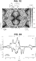
- FIGS. 7A and 7B show that the band that forms the largest Fermi surface and another band intersect with each other to provide linear dispersion in the vicinity of the Fermi energy E F , and density of states (DOS) increases because the dispersions of the two bands are almost flat.
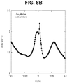
- FIG. 8A shows a spin-decomposed density of states of Co 2 MnGa obtained from the first-principles calculations
- FIG. 8B shows the density of states near the Fermi energy E F .
- the density of states has peaks around the Fermi energy E F and around 60 meV. That is, the density of states of Co 2 MnGa has a local maximum value in the vicinity of Fermi energy E F .
- v 2/ v 1 ⁇ 1 corresponds to type-I Weyl fermions
- v 2 /v 1 >1 corresponds to type-II Weyl fermions.
- the logarithmic divergence of ⁇ yx / ⁇ E at the quantum critical point can lead to ⁇ yx ⁇ Tlog(
- this logarithmic divergence can lead to ⁇ yx ⁇ Tlog(k B T/(hv 1 k 0 2 ⁇ )) behavior at high temperatures k B T>
- the temperature dependence of ⁇ yx can be understood in terms of a scaling function of the low energy theory in the vicinity of the quantum critical point between the type I and the type II over a decade of temperatures.
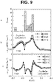
- a graph a in FIG. 9 shows energy dependence of the number of Weyl points for the magnetization along [110]
- the chirality (right handed and left handed) of Weyl points is denoted by +1 and -1.
- - ⁇ yx /T has a sharp peak and the number of Weyl points is large in the vicinity of E 0 ⁇ 0.02 eV.
- the Weyl points can exist within the range of ⁇ 0.1 eV from the Fermi energy E F .
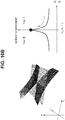
- FIGS. 10A and 10B each schematically shows a relation between the band dispersion and the Nernst coefficient.
- the Nernst coefficient in this case is about 0.7 ⁇ V/K.
- the Nernst coefficient increases with approaching the quantum critical point.
- the two energy bands provide flat dispersion, and the density of states at the Weyl points increases.
- the Nernst coefficient has a local maximum value, reaching about 7 ⁇ V/K.
- the flat dispersion increases the Nernst coefficient by one order of magnitude.
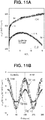
- thermoelectric conversion element 1 To provide further evidence for the existence of Weyl fermions in Co 2 MnGa, measurements of magnetic field dependence of the longitudinal conductivity ⁇ xx with different electric current directions and measurements of angle dependence of magneto-conductivity ⁇ xx (B)- ⁇ xx (0) with different electric current directions were performed on the thermoelectric conversion element 1.
- 9 T for I ⁇ [100], I ⁇ [110], and I ⁇ [111].
- 11B indicates that the magneto-conductivity displays cos 2 ⁇ behavior.
- the electric current I is allowed to flow easily in high magnetic fields (e.g., above
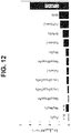
- FIG. 12 shows comparison of magnitude of the Peltier coefficient
- the magnitude of the Peltier coefficient of Co 2 MnGa is significantly greater than those of the other ferromagnets and the antiferromagnet Mn 3 Sn.
- thermoelectric conversion device including the thermoelectric conversion element according to the embodiments in the form of modules.
- FIG. 13 shows an exterior configuration of a thermoelectric conversion device 20 according to the embodiments.
- the thermoelectric conversion device 20 includes a substrate 22 and a power generator 23 placed on the substrate 22.
- a temperature difference is created in the power generator 23 in the direction of the heat current, and an electric voltage V is generated in the power generator 23 by the anomalous Nernst effect.
- the substrate 22 has a first surface 22a on which the power generator 23 is placed, and a second surface 22b opposite to the first surface 22a. Heat from a heat source (not shown) is applied onto the second surface 22b.
- the power generator 23 includes a plurality of thermoelectric conversion elements 24 and a plurality of thermoelectric conversion elements 25, each having a three-dimensional L shape and being made of a material identical to that of the thermoelectric conversion element 1 shown in FIG. 3 .
- the plurality of thermoelectric conversion elements 24 and the plurality of thermoelectric conversion elements 25 are alternately arranged in parallel to one another on the substrate 22 in a direction (direction y) perpendicular to a longitudinal direction (direction x) of the thermoelectric conversion elements.
- the number of the thermoelectric conversion elements 24 and 25 that constitute the power generator 23 is not limited to a specific number.
- the plurality of thermoelectric conversion elements 24 and the plurality of thermoelectric conversion elements 25 are arranged such that magnetization M1 of the thermoelectric conversion elements 24 is oriented opposite to a direction of magnetization M2 of the thermoelectric conversion elements 25. Further, the plurality of thermoelectric conversion elements 24 has the Nernst coefficient with the same sign as that of the Nernst coefficient of the plurality of thermoelectric conversion elements 25.
- thermoelectric conversion elements 24 has a first end face 24a and a second end face 24b, both of which are parallel to the longitudinal direction (direction x) of each of the thermoelectric conversion elements 24.
- Each of the thermoelectric conversion elements 25 has a first end face 25a and a second end face 25b, both of which are parallel to the longitudinal direction (direction x) of each of the thermoelectric conversion elements 25.
- the first end face 25a of the thermoelectric conversion element 25 is connected to the second end face 24b of one thermoelectric conversion element 24 adjacent thereto on one side thereof, and the second end face 25b of the thermoelectric conversion element 25 is connected to the first end face 24a of another thermoelectric conversion element 24 adjacent thereto on the opposite side thereof.
- the plurality of thermoelectric conversion elements 24 and the plurality of thermoelectric conversion elements 25 are electrically connected in series to one another. That is, the power generator 23 is provided on the first surface 22a of the substrate 22 in a serpentine shape.
- the heat current Q flows in the direction +z toward the power generator 23.
- the anomalous Nernst effect causes each of the thermoelectric conversion elements 24 to generate electromotive force E1 in the direction (direction -x) perpendicular to both the direction of the magnetization M1 (direction -y) and the direction of the heat current Q (direction +z).
- the anomalous Nernst effect causes each of the thermoelectric conversion elements 25 to generate electromotive force E2 in the direction (direction +x) perpendicular to both the direction of the magnetization M2 (direction +y) and the direction of the heat current Q (direction +z).
- thermoelectric conversion device 20 in FIG. 13 another configuration may be employed in which the plurality of thermoelectric conversion elements 24 and the plurality of thermoelectric conversion elements 25 are arranged such that the thermoelectric conversion element 24 has the Nernst coefficient which is opposite in sign to the Nernst coefficient of the thermoelectric conversion element 25, and the thermoelectric conversion element 24 and the thermoelectric conversion element 25 share the same direction of magnetization (that is, the magnetization M1 and the magnetization M2 have the same direction).
- thermoelectric conversion device should not be limited to the above-described embodiment shown in FIG. 13 .
- the anomalous Nernst effect allows temperature gradient, a direction of magnetization, and a direction of an electric voltage to be perpendicular to one another, which makes it possible to produce a thin sheet-shaped thermoelectric conversion element.
- FIG. 14 shows an exterior configuration of a thermoelectric conversion device 30 including a sheet-shaped thermoelectric conversion element 32.
- the thermoelectric conversion device 30 includes a hollow member 31 and an elongated sheet-shaped thermoelectric conversion element 32 covering (winding around) an outer surface of the hollow member 31.
- the thermoelectric conversion element 32 is made of a material identical to that of the thermoelectric conversion element 1 shown in FIG. 3 .
- a direction of magnetization of the thermoelectric conversion element 32 is parallel to a longitudinal direction (direction x) of the hollow member 31.
- the anomalous Nernst effect When heat current flows in a direction perpendicular to the longitudinal direction (direction x) of the hollow member 31 and a temperature gradient is created in a direction from inside to outside the hollow member 31, the anomalous Nernst effect generates an electric voltage V along a longitudinal direction of the elongated thermoelectric conversion element 32 (i.e., a direction perpendicular to the direction of magnetization and the direction of heat current).
- thermoelectric conversion element(s) a longitudinal length of the thermoelectric conversion element(s) be denoted by L, and a thickness (height) of the thermoelectric conversion element(s) be denoted by H.
- the electric voltage generated by the anomalous Nernst effect is proportional to L/H. That is, the longer and thinner the thermoelectric conversion element(s), the greater the generated voltage.
- the anomalous Nernst effect is expected to be enhanced by employing the power generator 23 ( FIG. 13 ) including the plurality of thermoelectric conversion elements 24 and the plurality of thermoelectric conversion elements 25 which are electrically connected in series to one another in a serpentine shape or employing the elongated sheet-shaped thermoelectric conversion element 32 ( FIG. 14 ).
- thermoelectric conversion device 20 and the thermoelectric conversion device 30 can be used for a variety of apparatuses.
- a heat flux sensor provided with the thermoelectric conversion device enables evaluation of heat insulation performance of buildings.
- an exhaust system of a motorcycle or other vehicles provided with the thermoelectric conversion device allows utilization of heat of exhaust gas (waste heat) for power generation. It is therefore possible to make effective use of the thermoelectric conversion device as an auxiliary power supply.
- the embodiments have focused on the electric voltage generated by the anomalous Nernst effect. Instead, the output voltage can be increased by virtue of synergy among the electric voltage generated by the Seebeck effect resulting from a temperature difference, the Hall effect that occurs based on the electric voltage generated by the Seebeck effect, and the electric voltage generated by the anomalous Nernst effect.
- Co 2 MnGa is a material that enhances the anomalous Nernst effect based on the existence of Weyl fermions.
- examples of potential materials that are likely to enhance the anomalous Nernst effect based on the existence of Weyl fermions may include Co 2 MnAl, Co 2 MnIn, Mn 3 Ga, Mn 3 Ge, Fe 2 NiGa, CoTiSb, CoVSb, CoCrSb, CoMnSb, and TiGa 2 Mn.
Landscapes
- Hall/Mr Elements (AREA)
- Hard Magnetic Materials (AREA)
Abstract
Description
- The present invention relates to a thermoelectric conversion element and a thermoelectric conversion device including the thermoelectric conversion element.
- In recent years, there has been proposed thermoelectric conversion devices using the anomalous Nernst effect (see
Patent Literature 1, for example). The anomalous Nernst effect is a phenomenon observed when heat current flowing through a magnetic material creates a temperature difference, which generates an electric voltage in a direction perpendicular to both a direction of magnetization and a temperature gradient. - The Seebeck effect is well known as a thermoelectric mechanism that also generates an electric voltage due to a temperature gradient. The Seebeck effect generates the electric voltage in a direction of the temperature gradient, which causes a complicated three-dimensional structure of thermoelectric modules. This makes it difficult to achieve large-area thermoelectric modules and film-shaped thermoelectric modules. In addition, toxic and rare materials are used in the Seebeck effect, leading to fragile, vibration sensitive modules, and a high manufacturing cost. In contrast, the anomalous Nernst effect generates the electric voltage in the direction perpendicular to the temperature gradient, which enables a lateral configuration of thermoelectric modules to cover a heat source. Such a configuration is advantageous for achieving large-area thermoelectric modules and film-shaped thermoelectric modules. Further, inexpensive, low-toxicity, highly durable materials can be selected for the anomalous Nernst effect.
- Patent Literature 1: Japanese Patent No.
6,079,995 - Although the anomalous Nernst effect has advantages over the Seebeck effect as described above, the current power generation capacity by the anomalous Nernst effect using typical magnetic materials is still insufficient for practical applications.
- In view of the foregoing, an object of the present invention is to provide a thermoelectric conversion element that can exhibit a much larger anomalous Nernst effect than ever before, and to provide a thermoelectric conversion device including the thermoelectric conversion element.
- A thermoelectric conversion element according to a first aspect of the present invention is made of a material with a band structure having Weyl points in the vicinity of Fermi energy. The thermoelectric conversion element has a thermoelectric mechanism for generating electromotive force by the anomalous Nernst effect.
- A thermoelectric conversion device according to a second aspect of the present invention includes a substrate, and a power generator provided on the substrate and including a plurality of thermoelectric conversion elements. Each of the plurality of thermoelectric conversion elements has a shape extending in one direction, and is made of a material with a band structure having Weyl points in the vicinity of the Fermi energy. In the power generator, the plurality of thermoelectric conversion elements is arranged in parallel to one another in a direction perpendicular to the one direction and electrically connected in series to one another in a serpentine shape.
- A thermoelectric conversion device according to a third aspect of the present invention includes: a thermoelectric conversion element made of a material with a band structure having Weyl points in the vicinity of the Fermi energy; and a hollow member. The thermoelectric conversion element is a sheet-shaped element covering an outer surface of the hollow member.
- According to the present invention, it is possible to achieve a much larger anomalous Nernst effect than ever before by using a thermoelectric conversion element made of a material whose band structure has Weyl points in the vicinity of Fermi energy.
-
-
FIG. 1 is a schematic view of a band dispersion indicating a relation between energy and momentum of Weyl fermions. -
FIG. 2 is a schematic view of a crystal structure of Co2MnGa. -
FIG. 3 is a schematic view of a configuration of a thermoelectric conversion element according to embodiments of the present invention. -
FIG. 4 shows graphs illustrating results of measurement of magnet field dependence and temperature dependence of the Nernst effect, the Hall effect, and magnetization of the thermoelectric conversion element. -
FIG. 5 shows graphs illustrating temperature dependence of longitudinal resistivity and the Seebeck coefficient of the thermoelectric conversion element at zero magnetic field. -
FIG. 6A shows graphs illustrating temperature dependence of Hall conductivity and the Peltier coefficient of the thermoelectric conversion element. -
FIG. 6B is a graph illustrating the temperature dependence of the Peltier coefficient inFIG. 6A in terms of a scaling function near a quantum critical point. -
FIG. 7A is a schematic view of a band structure of Co2MnGa obtained from first-principles calculations. -
FIG. 7B is a schematic view of a band dispersion of Co2MnGa near Fermi energy, and an inset indicates a first Brillouin zone and symmetric points of a face-centered cubic lattice. -
FIG. 7C is a schematic view illustrating a band structure along U-Z-U near energy E∼20 meV (top panel) and a distribution of the Berry curvature in a ka=kb plane spanned by momentum kUZ along U-Z and kc (bottom panel). -
FIG. 8A is a graph illustrating a spin-decomposed density of states of Co2MnGa obtained from the first-principles calculations. -
FIG. 8B is a graph illustrating the density of states near the Fermi energy inFIG. 8A . -
FIG. 9 shows graphs illustrating energy dependence of the number of Weyl points and energy dependence of the Hall conductivity and -αyx/T of the thermoelectric conversion element at absolute zero, the latter energy dependence being obtained from the first-principles calculations. -
FIG. 10A is a schematic view illustrating a relation between a band dispersion and the Nernst coefficient in type-I phase. -
FIG. 10B is a schematic view illustrating a relation between a band dispersion and the Nernst coefficient at the quantum critical point. -
FIG. 11A is a graph illustrating results of measurement of magnetic field dependence of longitudinal conductivity of the thermoelectric conversion element with different electric current directions. -
FIG. 11B is a graph illustrating results of measurement of angle dependence (angle between magnetic field and electric current) of magneto-conductivity of the thermoelectric conversion element with different electric current directions. -
FIG. 12 is a graph illustrating comparison of magnitude of the Peltier coefficient for various ferromagnets and antiferromagnet Mn3Sn. -
FIG. 13 is an exterior view illustrating an example of a thermoelectric conversion device including the thermoelectric conversion element according to the embodiments. -
FIG. 14 is an exterior view illustrating another example of a thermoelectric conversion device including the thermoelectric conversion element according to the embodiments. - Exemplary embodiments of the present invention will be described below with reference to the accompanying drawings.
- In recent years, it is theoretically known that topological electronic structures relate to a thermoelectric mechanism based on the anomalous Nernst effect. In particular, recent studies have indicated that the Berry curvature of Weyl points residing in the vicinity of Fermi energy EF can potentially enhance the anomalous Nernst effect, and it is therefore expected that search for materials containing the Weyl fermions and new material synthesis are effective in development of a thermoelectric conversion device using the anomalous Nernst effect.
- The Weyl fermions are massless fermions defined by the Dirac equation. As shown in
FIG. 1 , the Weyl points are present at intersections of linear band dispersions and appear in pairs with opposite chirality (right handed and left handed). A pair of Weyl points can be regarded as positive and negative magnetic poles in a fictitious magnetic field (Berry curvature) in a momentum space and is considered to affect motion of electrons in a material, as with magnetic fields in a real space. - Recent first-principles calculations have shown that metals with composition Co2TX are potential Weyl metals in which Weyl points exist in the momentum space near the Fermi energy EF. Here, T is a transition metal, and X is one of Si, Ge, Sn, Al, and Ga. As an example of such metals, the following embodiments are directed to Co2MnGa, which is a full Heusler ferromagnet.
-
FIG. 2 schematically shows a crystal structure of Co2MnGa. Co2MnGa has a L21-type cubic full Heusler structure as shown inFIG. 2 . A unit cell of the L21 structure consists of four face-centered cubic (fcc) sublattices with Co atoms at (1/4, 1/4, 1/4) and (3/4, 3/4, 3/4), Mn atom at (0, 0, 0) and Ga atom at (1/2, 1/2, 1/2) in a lattice coordinate system. The crystal structure of Co2MnGa can be determined by a variety of diffraction methods, such as X-ray diffraction. - Next, a thermoelectric conversion element according to the embodiments of the present invention and a thermoelectric mechanism thereof will be described with reference to
FIG. 3 . As shown inFIG. 3 , an assumption is made that athermoelectric conversion element 1 according to the embodiments is made of Co2MnGa, has a box shape extending in one direction (direction y), has a thickness (length in a direction z) greater than or equal to 0.1 µm, and is magnetized in a direction +z. When heat current Q (∼∇T) flows through thethermoelectric conversion element 1 in a direction +x, a temperature difference is created in the direction +x. As a result, the anomalous Nernst effect generates electromotive force V (∼M×∇T) in thethermoelectric conversion element 1 in an outer product direction (direction y) perpendicular to both the direction of the heat current Q (direction +x) and the direction of magnetization M (direction +z). - Reference will now be made to a verification experiment of the anomalous Nernst effect of the
thermoelectric conversion element 1. - Single crystals of Co2MnGa were prepared by the Czochralski method after making polycrystalline samples by arc-melting Co, Mn, and Ga with an appropriate ratio. X-ray diffraction showed that the produced Co2MnGa had a lattice constant a=5.77(3) angstroms. In the experiment, three box-shaped samples with a size of 7.5×2.0×1.3 mm3 were produced as the
thermoelectric conversion element 1. The three samples are distinguished according to crystal orientations parallel to directions of magnetic fields B, and a B||[100] sample, a B||[110] sample, and a B||[111] sample are denoted by #100, #110, and #111, respectively. In the embodiments, transport phenomena (the Nernst effect, the Seebeck effect, and the Hall effect) were measured for each sample by using a known method. -
FIGS. 4 to 6A show the results of the measurement of the Nernst effect, the Seebeck effect, and the Hall effect for each sample. - A graph a in
FIG. 4 shows magnetic field dependence of a Nernst coefficient -Syx at room temperature (T=300 K) and shows observational results obtained when a magnetic field B parallel to [100], a magnetic field B parallel to [110], and a magnetic field B parallel to [111] are applied to the samples and the heat current Q parallel to [001] or [10-1] flows through the samples. A graph b inFIG. 4 shows temperature dependence of -Syx obtained when a magnetic field B=2 T is applied to each of the samples. As is clear from the graph b inFIG. 4 , -Syx increases with elevating temperature, reaches |Syx|∼6 µV/K at room temperature, and even approaches |Syx|∼8 µV/K at 400 K, which are one order of magnitude larger than typical observed values known for the anomalous Nernst effect. - A ratio of the observed value -Syx to the Seebeck coefficient Sxx indicated by a graph b in
FIG. 5 (namely, the Nernst angle θN≈tanθN=Syx/Sxx) is also an unprecedented large value. In fact, |Syx/Sxx| is greater than 0.2, as shown by a right vertical axis of the graph a inFIG. 4 . The graphs a and b inFIG. 4 further indicate that there is almost no anisotropy in Syx. - As shown in graphs c and d of
FIG. 4 , the Hall resistivity ρyx reaches 15 µΩcm at room temperature and reaches a maximum 16 µΩcm around 320 K. The Hall angle θH≈tanθH=ρyx/ρxx (a right vertical axis of the graph c inFIG. 4 ) is also large and exceeds 0.1 at room temperature. Here, ρxx is longitudinal resistivity. A graph a inFIG. 5 shows temperature dependence of ρxx at zero magnetic field. - Graphs e and f in
FIG. 4 show magnetic field dependence of the magnetization M at room temperature and temperature dependence of the magnetization M at magnetic field B=2 T, respectively. The graphs a, c, and e inFIG. 4 show that the Hall effect and the Nernst effect have nearly the same magnetic field dependence as that of the magnetization curve. This indicates that the anomalous contribution (∝M) to the Hall effect and the Nernst effect is dominant and the normal contribution (∝B) is negligibly small at T=300 K. As indicated by the graphs e and f inFIG. 4 , saturated magnetization Ms reaches 3.8 µB at T=300 K, gradually grows on cooling, and reaches about 4 µB at T=5 K, which is consistent with the predicted value based on the Slater-Pauling rule. The graphs e and f inFIG. 4 indicate that the anisotropy for the magnetization is negligibly small at T=300 K, which is fully consistent with the cubic structure. - The observed Hall resistivity |ρyx|∼15 µΩcm is one of the largest known for the anomalous Hall effect. Similarly, the Hall conductivity is also exceptionally large. A graph a in
FIG. 6A shows temperature dependence of the Hall conductivity σyx at B=2 T. Here, σyx=-ρyx/(ρxx 2+ρyx 2) is satisfied. -σyx monotonically increases on cooling and reaches -σyx∼2000 Ω-1cm-1 at absolute zero. This value is of the same order of magnitude as the one known for the layered quantum Hall effect. - The Nernst coefficient Syx can be defined by the Peltier coefficient αyx. In general, electric current is generated by both electric field ε and temperature gradient VT and expressed by J=σ·ε-α·∇T. Here, J, σ and α are an electric current density tensor, an electric conductivity tensor, and a thermoelectric conductivity tensor, respectively. Assuming that the direction of the magnetic field B is parallel to the direction z and the temperature gradient VT is parallel to the direction x, and setting J=0, the following is obtained: Jy=σyxSxx+σxxSyx-αyx=0. Here, a cubic symmetry provides σxx=σyy. That is, the Peltier coefficient, which is a transverse thermoelectric coefficient, is given by the following Expression (1):

- According to Expression (1), the Peltier coefficient determines the magnitude of the Nernst coefficient, and it is effective to evaluate the Peltier coefficient for determination of the anomalous Nernst effect.
- A graph b in
FIG. 6A shows the results of calculation of temperature dependence of -αyx using Expression (1) and the values obtained fromFIGS. 4 and5 and the graph a inFIG. 6A . As indicated by the graph b inFIG. 6A , -αyx increases almost linearly with T up to T∼25 K, reaches a maximum around T∼140 K, and then gradually decreases with a rise in T. Notice that the curve of the temperature dependence of -αyx closely resembles-TlogT behavior. In more detail, by plotting data of -αyx/T (right vertical axis ofFIG. 6B ) against logT, a crossover is found between two distinct behaviors: -αyx∼T at low temperatures and -αyx∼-TlogT at high temperatures. - -αyx∼T behavior at low temperatures is consistent with the Mott formula, which defines the relation between αyx at low temperatures (kBT<<EF) and the energy derivative of the Hall conductivity σyx at T=0 (αyx∼-(π2kB 2T/3e) (∂σyx/∂EF)). Here, kB is the Boltzmann constant. On the other hand, -αyx∼-TlogT behavior at high temperatures (between T∼30 K and T∼400 K) indicates violation of the Mott formula. The -TlogT behavior of the thermoelectric coefficient can be understood in terms of Weyl fermions, as will be described below.
- To provide evidence for the existence of Weyl points, the focus is first put on a Fermi surface closest to the Fermi energy EF of Co2MnGa.
FIG. 7A shows the band structure of Co2MnGa obtained from the first-principles calculations. Here, the magnetization M is 4.2 µB, and the magnetization direction is along [110]. InFIG. 7A , a band that forms the largest Fermi surface, which is located near the Brillouin zone boundary and closest to the Fermi energy EF (=0 eV), is drawn by a thick line.FIGS. 7A to 7C show that the Weyl points (+-) are located around E0≈20 meV in the vicinity of the Fermi energy EF, and this Fermi surface has a large Berry curvature |Ωz| in the vicinity of the Weyl points (+-) (FIG. 7C ). -
FIGS. 7B and7C show that the Weyl points (+-) are located on the Brillouin zone boundary along U-Z-U line at ±k0=±(2π/a)×0.15 in a ka=kb plane spanned by the momentum kUZ along U-Z and kc. InFIG. 7C , the distribution of z component of the Berry curvature |Ωz| in the ka=kb plane is expressed by grayscale, and the Weyl points (+-) appear at locations where the Berry curvature |Ωz| is relatively large (dense portion). The Weyl points can be searched in the Brillouin zone by a method of Fukui-Hatsugai-Suzuki (J. Phys. Soc. Jpn 74, 1674-1677 (2005)). -
FIGS. 7A and7B show that the band that forms the largest Fermi surface and another band intersect with each other to provide linear dispersion in the vicinity of the Fermi energy EF, and density of states (DOS) increases because the dispersions of the two bands are almost flat.FIG. 8A shows a spin-decomposed density of states of Co2MnGa obtained from the first-principles calculations, andFIG. 8B shows the density of states near the Fermi energy EF. As shown inFIG. 8B , the density of states has peaks around the Fermi energy EF and around 60 meV. That is, the density of states of Co2MnGa has a local maximum value in the vicinity of Fermi energy EF. - The right handed (+) and left handed (-) Weyl fermions are described by low-energy Hamiltonians, as given by Expression (2).

- At the quantum critical point (v2/v1=1), the energy derivative of the Hall conductivity ∂σyx/∂E displays log divergent behavior at low energy. The low energy theory suggests that αyx(T, µ) indicating temperature and chemical potential dependence of the Peltier coefficient in the vicinity of the quantum critical point can be expressed in terms of a dimensionless scaling function G over a wide range of temperatures (see
FIG. 6B ). Here, µ is the chemical potential.FIG. 6B shows that the scaling functions obtained from experiment (T0=550 k) and density functional theory (DFT) calculations (T0=6000 K) match with the results from the low energy theory over a decade of temperatures (solid line inFIG. 6B when (µ-E0)/kBT0=-0.05). - That is, based on the scaling function of the low energy theory, the logarithmic divergence of ∂σyx/∂E at the quantum critical point can lead to αyx∼Tlog(|EF-E0|/(hv1k0/2π)) behavior at low temperatures. On the other hand, this logarithmic divergence can lead to αyx∼Tlog(kBT/(hv1k02π)) behavior at high temperatures kBT>|EF-E0|, which does not follow the Mott formula (αyx∼T). Thus, the temperature dependence of αyx can be understood in terms of a scaling function of the low energy theory in the vicinity of the quantum critical point between the type I and the type II over a decade of temperatures.
- When the chemical potential µ is tuned to the Weyl points (µ=E0), the scaling function does not follow the Mott formula even at any low temperature (broken line in
FIG. 6B ). - A graph a in
FIG. 9 shows energy dependence of the number of Weyl points for the magnetization along [110], a graph b inFIG. 9 shows energy dependence of -σyx at T=0 K, and a graph c inFIG. 9 shows energy dependence of -αyx/T at T=0 K. In the graph a ofFIG. 9 , the chirality (right handed and left handed) of Weyl points is denoted by +1 and -1. According to the graphs a, b and c, -αyx/T has a sharp peak and the number of Weyl points is large in the vicinity of E0∼0.02 eV. Further, in the vicinity of E∼-0.1 eV, -αyx/T has an extreme value and the number of Weyl points is much larger. Thus, the Weyl points can exist within the range of ±0.1 eV from the Fermi energy EF. -
FIGS. 10A and10B each schematically shows a relation between the band dispersion and the Nernst coefficient. As shown inFIG. 10A , with respect to the type-I Weyl fermions separated from the quantum critical point (v1=v2), two energy bands are in point contact with each other, and the density of states at the Weyl points is zero. The Nernst coefficient in this case is about 0.7 µV/K. The Nernst coefficient increases with approaching the quantum critical point. At the quantum critical point (FIG. 10B ), the two energy bands provide flat dispersion, and the density of states at the Weyl points increases. At this point, the Nernst coefficient has a local maximum value, reaching about 7 µV/K. Thus, the flat dispersion increases the Nernst coefficient by one order of magnitude. - As described above, the first-principles calculations of Co2MnGa show the existence of the type-I Weyl fermions, which are located at ±k0∼(2π/a)×0.15 in the vicinity of E0≈20 meV and have the tilt parameter of v2/v1=0.99, thereby obtaining the Nernst coefficient in the vicinity of the quantum critical point.
- To provide further evidence for the existence of Weyl fermions in Co2MnGa, measurements of magnetic field dependence of the longitudinal conductivity σxx with different electric current directions and measurements of angle dependence of magneto-conductivity σxx(B)-σxx(0) with different electric current directions were performed on the
thermoelectric conversion element 1. -
FIG. 11A is a graph illustrating the results of the measurements of the magnetic field dependence of the longitudinal conductivity σxx at T=0.1 K and T=5 K when the magnetic field B and the electric current I are parallel to each other (I||B) and when the magnetic field B and the electric current I are perpendicular to each other (I⊥B).FIG. 11B is a graph illustrating the results of the measurements of the angle dependence (an angle θ between the magnetic field B and the electric current I) of the magneto-conductivity at T=5 K and |B|=9 T for I∥[100], I∥[110], and I∥[111]. θ=0°, 180° and 360° correspond to I∥B, and θ=90° and 270° correspond to I⊥B.FIG. 11B indicates that the magneto-conductivity displays cos2θ behavior. As is clear fromFIGS. 11A and 11B , the electric current I is allowed to flow easily in high magnetic fields (e.g., above |B|∼6 T) when the magnetic field B is parallel to the electric current I. This implies occurrence of chiral anomaly that appears in a material containing Weyl fermions. -
FIG. 12 shows comparison of magnitude of the Peltier coefficient |αyx| for various ferromagnets and antiferromagnet Mn3Sn. As is clear fromFIG. 12 , the magnitude of the Peltier coefficient of Co2MnGa is significantly greater than those of the other ferromagnets and the antiferromagnet Mn3Sn. - Next, reference will be made to a thermoelectric conversion device including the thermoelectric conversion element according to the embodiments in the form of modules.
-
FIG. 13 shows an exterior configuration of athermoelectric conversion device 20 according to the embodiments. Thethermoelectric conversion device 20 includes asubstrate 22 and apower generator 23 placed on thesubstrate 22. In thethermoelectric conversion device 20, when the heat current Q flows from thesubstrate 22 side toward thepower generator 23, a temperature difference is created in thepower generator 23 in the direction of the heat current, and an electric voltage V is generated in thepower generator 23 by the anomalous Nernst effect. - The
substrate 22 has afirst surface 22a on which thepower generator 23 is placed, and asecond surface 22b opposite to thefirst surface 22a. Heat from a heat source (not shown) is applied onto thesecond surface 22b. - The
power generator 23 includes a plurality ofthermoelectric conversion elements 24 and a plurality ofthermoelectric conversion elements 25, each having a three-dimensional L shape and being made of a material identical to that of thethermoelectric conversion element 1 shown inFIG. 3 . As shown inFIG. 13 , the plurality ofthermoelectric conversion elements 24 and the plurality ofthermoelectric conversion elements 25 are alternately arranged in parallel to one another on thesubstrate 22 in a direction (direction y) perpendicular to a longitudinal direction (direction x) of the thermoelectric conversion elements. The number of thethermoelectric conversion elements power generator 23 is not limited to a specific number. - The plurality of
thermoelectric conversion elements 24 and the plurality ofthermoelectric conversion elements 25 are arranged such that magnetization M1 of thethermoelectric conversion elements 24 is oriented opposite to a direction of magnetization M2 of thethermoelectric conversion elements 25. Further, the plurality ofthermoelectric conversion elements 24 has the Nernst coefficient with the same sign as that of the Nernst coefficient of the plurality ofthermoelectric conversion elements 25. - Each of the
thermoelectric conversion elements 24 has afirst end face 24a and asecond end face 24b, both of which are parallel to the longitudinal direction (direction x) of each of thethermoelectric conversion elements 24. Each of thethermoelectric conversion elements 25 has afirst end face 25a and asecond end face 25b, both of which are parallel to the longitudinal direction (direction x) of each of thethermoelectric conversion elements 25. Thefirst end face 25a of thethermoelectric conversion element 25 is connected to thesecond end face 24b of onethermoelectric conversion element 24 adjacent thereto on one side thereof, and thesecond end face 25b of thethermoelectric conversion element 25 is connected to thefirst end face 24a of anotherthermoelectric conversion element 24 adjacent thereto on the opposite side thereof. With this structure, the plurality ofthermoelectric conversion elements 24 and the plurality ofthermoelectric conversion elements 25 are electrically connected in series to one another. That is, thepower generator 23 is provided on thefirst surface 22a of thesubstrate 22 in a serpentine shape. - When heat is applied from the heat source onto the
second surface 22b of thesubstrate 22, the heat current Q flows in the direction +z toward thepower generator 23. When the heat current Q creates a temperature difference, the anomalous Nernst effect causes each of thethermoelectric conversion elements 24 to generate electromotive force E1 in the direction (direction -x) perpendicular to both the direction of the magnetization M1 (direction -y) and the direction of the heat current Q (direction +z). The anomalous Nernst effect causes each of thethermoelectric conversion elements 25 to generate electromotive force E2 in the direction (direction +x) perpendicular to both the direction of the magnetization M2 (direction +y) and the direction of the heat current Q (direction +z). - Since the
thermoelectric conversion elements 24 and thethermoelectric conversion elements 25, which are arranged in parallel to one another, are electrically connected in series to one another as described above, the electromotive force E1 generated in onethermoelectric conversion element 24 can be applied to the adjacentthermoelectric conversion element 25. Since the direction of the electromotive force E1 generated in the onethermoelectric conversion element 24 is opposite to the direction of the electromotive force E2 generated in the adjacentthermoelectric conversion element 25, the electromotive force in thethermoelectric conversion element 24 and the electromotive force in the adjacentthermoelectric conversion element 25 are added up, thereby increasing an output voltage V. - As a modification of the
thermoelectric conversion device 20 inFIG. 13 , another configuration may be employed in which the plurality ofthermoelectric conversion elements 24 and the plurality ofthermoelectric conversion elements 25 are arranged such that thethermoelectric conversion element 24 has the Nernst coefficient which is opposite in sign to the Nernst coefficient of thethermoelectric conversion element 25, and thethermoelectric conversion element 24 and thethermoelectric conversion element 25 share the same direction of magnetization (that is, the magnetization M1 and the magnetization M2 have the same direction). - Aspects of the thermoelectric conversion device according to the embodiments should not be limited to the above-described embodiment shown in
FIG. 13 . The anomalous Nernst effect allows temperature gradient, a direction of magnetization, and a direction of an electric voltage to be perpendicular to one another, which makes it possible to produce a thin sheet-shaped thermoelectric conversion element. -
FIG. 14 shows an exterior configuration of athermoelectric conversion device 30 including a sheet-shapedthermoelectric conversion element 32. Specifically, thethermoelectric conversion device 30 includes ahollow member 31 and an elongated sheet-shapedthermoelectric conversion element 32 covering (winding around) an outer surface of thehollow member 31. Thethermoelectric conversion element 32 is made of a material identical to that of thethermoelectric conversion element 1 shown inFIG. 3 . A direction of magnetization of thethermoelectric conversion element 32 is parallel to a longitudinal direction (direction x) of thehollow member 31. When heat current flows in a direction perpendicular to the longitudinal direction (direction x) of thehollow member 31 and a temperature gradient is created in a direction from inside to outside thehollow member 31, the anomalous Nernst effect generates an electric voltage V along a longitudinal direction of the elongated thermoelectric conversion element 32 (i.e., a direction perpendicular to the direction of magnetization and the direction of heat current). - In
FIGS. 13 and14 , let a longitudinal length of the thermoelectric conversion element(s) be denoted by L, and a thickness (height) of the thermoelectric conversion element(s) be denoted by H. The electric voltage generated by the anomalous Nernst effect is proportional to L/H. That is, the longer and thinner the thermoelectric conversion element(s), the greater the generated voltage. Hence, the anomalous Nernst effect is expected to be enhanced by employing the power generator 23 (FIG. 13 ) including the plurality ofthermoelectric conversion elements 24 and the plurality ofthermoelectric conversion elements 25 which are electrically connected in series to one another in a serpentine shape or employing the elongated sheet-shaped thermoelectric conversion element 32 (FIG. 14 ). - The
thermoelectric conversion device 20 and thethermoelectric conversion device 30 can be used for a variety of apparatuses. For example, a heat flux sensor provided with the thermoelectric conversion device enables evaluation of heat insulation performance of buildings. Further, an exhaust system of a motorcycle or other vehicles provided with the thermoelectric conversion device allows utilization of heat of exhaust gas (waste heat) for power generation. It is therefore possible to make effective use of the thermoelectric conversion device as an auxiliary power supply. - The embodiments have focused on the electric voltage generated by the anomalous Nernst effect. Instead, the output voltage can be increased by virtue of synergy among the electric voltage generated by the Seebeck effect resulting from a temperature difference, the Hall effect that occurs based on the electric voltage generated by the Seebeck effect, and the electric voltage generated by the anomalous Nernst effect.
- The embodiments have been described in which Co2MnGa is a material that enhances the anomalous Nernst effect based on the existence of Weyl fermions. In addition to Co2MnGa, examples of potential materials that are likely to enhance the anomalous Nernst effect based on the existence of Weyl fermions may include Co2MnAl, Co2MnIn, Mn3Ga, Mn3Ge, Fe2NiGa, CoTiSb, CoVSb, CoCrSb, CoMnSb, and TiGa2Mn.
-
- 1, 24, 25, 32
- Thermoelectric conversion element
- 20, 30
- Thermoelectric conversion device
- 22
- Substrate
- 23
- Power generator
- 31
- Hollow member
Claims (11)
- A thermoelectric conversion element made of a material with a band structure having Weyl points in a vicinity of Fermi energy,
wherein the thermoelectric conversion element has a thermoelectric mechanism for generating electromotive force by anomalous Nernst effect. - The thermoelectric conversion element according to claim 1, wherein a density of states of the material has energy dependence having an extreme value in the vicinity of the Fermi energy.
- The thermoelectric conversion element according to claim 1 or 2, wherein a thermoelectric coefficient that defines the electromotive force has temperature dependence proportional to -TlogT, where T is a temperature.
- The thermoelectric conversion element according to any one of claims 1 to 3, wherein the material shows ferromagnetism.
- The thermoelectric conversion element according to any one of claims 1 to 4, wherein the material has a cubic crystal structure.
- The thermoelectric conversion element according to any one of claims 1 to 5, wherein the material has a full Heusler crystal structure.
- The thermoelectric conversion element according to any one of claims 1 to 6, wherein the Weyl points of the material exist within a range of ±0.1 eV from the Fermi energy.
- The thermoelectric conversion element according to any one of claims 1 to 7, wherein the band structure of the material is obtained from first-principles calculations.
- The thermoelectric conversion element according to any one of claims 1 to 8, wherein the thermoelectric conversion element has a thickness greater than or equal to 0.1 µm.
- A thermoelectric conversion device comprising:a substrate; anda power generator provided on the substrate and including a plurality of thermoelectric conversion elements,wherein each of the plurality of thermoelectric conversion elements has a shape extending in one direction, and is made of a material identical to that of the thermoelectric conversion element according to any one of claims 1 to 9, andin the power generator, the plurality of thermoelectric conversion elements is arranged in parallel to one another in a direction perpendicular to the one direction and electrically connected in series to one another in a serpentine shape.
- A thermoelectric conversion device comprising:the thermoelectric conversion element according to any one of claims 1 to 9; anda hollow member,wherein the thermoelectric conversion element is a sheet-shaped element covering an outer surface of the hollow member.
Applications Claiming Priority (2)
| Application Number | Priority Date | Filing Date | Title |
|---|---|---|---|
| US201762528236P | 2017-07-03 | 2017-07-03 | |
| PCT/JP2018/025276 WO2019009308A1 (en) | 2017-07-03 | 2018-07-03 | Thermoelectric conversion element and thermoelectric conversion device |
Publications (3)
| Publication Number | Publication Date |
|---|---|
| EP3651218A1 true EP3651218A1 (en) | 2020-05-13 |
| EP3651218A4 EP3651218A4 (en) | 2021-04-07 |
| EP3651218B1 EP3651218B1 (en) | 2025-07-02 |
Family
ID=64950052
Family Applications (1)
| Application Number | Title | Priority Date | Filing Date |
|---|---|---|---|
| EP18827510.1A Active EP3651218B1 (en) | 2017-07-03 | 2018-07-03 | Thermoelectric conversion element and thermoelectric conversion device |
Country Status (5)
| Country | Link |
|---|---|
| US (1) | US11683985B2 (en) |
| EP (1) | EP3651218B1 (en) |
| JP (2) | JP7276856B2 (en) |
| CN (2) | CN110785862B (en) |
| WO (1) | WO2019009308A1 (en) |
Cited By (4)
| Publication number | Priority date | Publication date | Assignee | Title |
|---|---|---|---|---|
| EP4141976A4 (en) * | 2020-04-23 | 2024-08-14 | The University of Tokyo | Thermoelectric conversion element and thermoelectric conversion device |
| EP4383993A4 (en) * | 2021-08-06 | 2025-07-30 | Univ Tokyo | THERMOELECTRIC CONVERTER ELEMENT |
| EP4383992A4 (en) * | 2021-08-06 | 2025-07-30 | Univ Tokyo | THERMOELECTRIC CONVERTER ELEMENT |
| EP4412437A4 (en) * | 2021-09-29 | 2025-09-10 | Nitto Denko Corp | THERMOELECTRIC TRANSDUCER ELEMENT AND SENSOR |
Families Citing this family (16)
| Publication number | Priority date | Publication date | Assignee | Title |
|---|---|---|---|---|
| US10256391B2 (en) * | 2017-08-25 | 2019-04-09 | International Business Machines Corporation | Thermoelectric device |
| US11011692B2 (en) * | 2017-10-11 | 2021-05-18 | Ohio State Innovation Foundation | Thermoelectric device utilizing non-zero berry curvature |
| CN113728447B (en) | 2019-04-26 | 2025-07-08 | 国立大学法人东京大学 | Thermoelectric conversion element and thermoelectric conversion device |
| WO2021059391A1 (en) * | 2019-09-25 | 2021-04-01 | 日本電気株式会社 | Heat-flow sensor |
| JP7342623B2 (en) | 2019-10-31 | 2023-09-12 | Tdk株式会社 | Thermoelectric conversion element and thermoelectric conversion device equipped with the same |
| JP7243573B2 (en) * | 2019-10-31 | 2023-03-22 | Tdk株式会社 | Thermoelectric conversion element and manufacturing method thereof |
| JP7371980B2 (en) * | 2020-03-19 | 2023-10-31 | 国立研究開発法人物質・材料研究機構 | Vertical thermoelectric conversion element, and thermoelectric power generation application equipment or heat flow sensor using the same |
| JP7709717B2 (en) * | 2020-08-31 | 2025-07-17 | 国立大学法人 東京大学 | Thermoelectric elements and thermoelectric devices |
| WO2022176966A1 (en) * | 2021-02-17 | 2022-08-25 | 国立大学法人東京大学 | Thermoelectric device |
| JP7751321B2 (en) * | 2021-06-14 | 2025-10-08 | 国立研究開発法人物質・材料研究機構 | Thermoelectric power generation device |
| CN117501859A (en) * | 2021-06-30 | 2024-02-02 | 株式会社村田制作所 | Thermoelectric conversion device |
| WO2024143145A1 (en) * | 2022-12-28 | 2024-07-04 | TopoLogic株式会社 | Measuring system |
| US12410950B2 (en) * | 2022-12-29 | 2025-09-09 | Toyota Motor Engineering & Manufacturing North America, Inc. | Nano thermal diode based on polarization control of nanoparticles on graphene nanograting |
| KR20260046426A (en) | 2023-07-24 | 2026-04-07 | 고쿠리츠다이가쿠호우진 도쿄다이가쿠 | Gd-Co-based metal powder, method of manufacturing the same, conductive molded body and thermoelectric conversion element |
| JP7890790B2 (en) * | 2023-09-19 | 2026-07-15 | 国立研究開発法人物質・材料研究機構 | Thermoelectric laminates and thermoelectric devices |
| WO2025258265A1 (en) * | 2024-06-14 | 2025-12-18 | 国立研究開発法人物質・材料研究機構 | Thermoelectric device and method for manufacturing thermoelectric device |
Family Cites Families (9)
| Publication number | Priority date | Publication date | Assignee | Title |
|---|---|---|---|---|
| JP2004103951A (en) * | 2002-09-11 | 2004-04-02 | Univ Saitama | Manufacturing method of thermoelectric material |
| JP6079995B2 (en) * | 2012-09-28 | 2017-02-15 | 国立大学法人東北大学 | Thermoelectric power generation device |
| JP6311487B2 (en) * | 2014-06-26 | 2018-04-18 | 日本電気株式会社 | Thermoelectric conversion structure and manufacturing method thereof |
| JP6398573B2 (en) | 2014-10-10 | 2018-10-03 | 日本電気株式会社 | Spin heat flow sensor and manufacturing method thereof |
| JP6231467B2 (en) * | 2014-11-27 | 2017-11-15 | トヨタ自動車株式会社 | Thermoelectric |
| US10210970B2 (en) * | 2015-05-21 | 2019-02-19 | The Board Of Trustees Of The Leland Stanford Junior University | Metallic-magnetic-domain-wall-based nonvolatile tunable resistor for memory and sensor applications |
| CN105161217B (en) * | 2015-07-07 | 2017-04-19 | 中国科学院上海微系统与信息技术研究所 | Perovskite type Sr2IrO4 monocrystalline thin film material preparation method |
| JP6611167B2 (en) | 2015-10-23 | 2019-11-27 | 国立大学法人 東京大学 | Thermoelectric conversion device and thermoelectric conversion element |
| US9643385B1 (en) * | 2015-12-02 | 2017-05-09 | The Board Of Trustees Of The University Of Alabama | Layered heusler alloys and methods for the fabrication and use thereof |
-
2018
- 2018-07-03 CN CN201880039897.5A patent/CN110785862B/en active Active
- 2018-07-03 JP JP2019527731A patent/JP7276856B2/en active Active
- 2018-07-03 WO PCT/JP2018/025276 patent/WO2019009308A1/en not_active Ceased
- 2018-07-03 CN CN202311297543.XA patent/CN117295385A/en active Pending
- 2018-07-03 EP EP18827510.1A patent/EP3651218B1/en active Active
- 2018-07-03 US US16/626,937 patent/US11683985B2/en active Active
-
2023
- 2023-04-26 JP JP2023072584A patent/JP7515214B2/en active Active
Cited By (4)
| Publication number | Priority date | Publication date | Assignee | Title |
|---|---|---|---|---|
| EP4141976A4 (en) * | 2020-04-23 | 2024-08-14 | The University of Tokyo | Thermoelectric conversion element and thermoelectric conversion device |
| EP4383993A4 (en) * | 2021-08-06 | 2025-07-30 | Univ Tokyo | THERMOELECTRIC CONVERTER ELEMENT |
| EP4383992A4 (en) * | 2021-08-06 | 2025-07-30 | Univ Tokyo | THERMOELECTRIC CONVERTER ELEMENT |
| EP4412437A4 (en) * | 2021-09-29 | 2025-09-10 | Nitto Denko Corp | THERMOELECTRIC TRANSDUCER ELEMENT AND SENSOR |
Also Published As
| Publication number | Publication date |
|---|---|
| US20200212282A1 (en) | 2020-07-02 |
| US11683985B2 (en) | 2023-06-20 |
| CN110785862B (en) | 2023-10-27 |
| JPWO2019009308A1 (en) | 2020-04-30 |
| EP3651218B1 (en) | 2025-07-02 |
| EP3651218A4 (en) | 2021-04-07 |
| CN110785862A (en) | 2020-02-11 |
| JP7515214B2 (en) | 2024-07-12 |
| WO2019009308A1 (en) | 2019-01-10 |
| JP7276856B2 (en) | 2023-05-18 |
| CN117295385A (en) | 2023-12-26 |
| JP2023083615A (en) | 2023-06-15 |
Similar Documents
| Publication | Publication Date | Title |
|---|---|---|
| EP3651218B1 (en) | Thermoelectric conversion element and thermoelectric conversion device | |
| Sakai et al. | Giant anomalous Nernst effect and quantum-critical scaling in a ferromagnetic semimetal | |
| Nakata et al. | Magnonic topological insulators in antiferromagnets | |
| Arnold et al. | Chiral Weyl pockets and Fermi surface topology of the Weyl semimetal TaAs | |
| Sheng et al. | Theory of the phonon Hall effect in paramagnetic dielectrics | |
| Zhou et al. | Giant anomalous Nernst effect in noncollinear antiferromagnetic Mn-based antiperovskite nitrides | |
| Guo et al. | Tuning transport coefficients of monolayer MoSi2N4 with biaxial strain | |
| Chen et al. | Topological Heusler Magnets‐Driven High‐Performance Transverse Nernst Thermoelectric Generators | |
| Sakai et al. | Thermoelectric power in transition-metal monosilicides | |
| Zhao et al. | Ab initio nonadiabatic molecular dynamics investigation on the dynamics of photogenerated spin hole current in Cu-doped Mo S 2 | |
| De et al. | Temperature dependence of the anomalous Nernst effect in Ni 2 Mn Ga shape memory alloy | |
| Nakamura et al. | Logarithmic criticality in transverse thermoelectric conductivity of the ferromagnetic topological semimetal CoMnSb | |
| Xue et al. | Extrinsic mechanisms of phonon magnetic moment | |
| Back et al. | Special issue on spin caloritronics | |
| Warnes | Electronic Materials | |
| Khalaf Al-zyadi et al. | Electronic and magnetic properties of bulk and surfaces half-Heusler alloy KCaB and its bulk thermoelectric properties | |
| JP5807483B2 (en) | Temperature measuring apparatus and temperature measuring method | |
| Patel et al. | Thermoelectricity in graphene: Effects of a gap and magnetic fields | |
| Damljanović et al. | Existence of semi-Dirac cones and symmetry of two-dimensional materials | |
| Fujii et al. | Giant density of states enhancement driven by a zero-mode Landau level in semimetallic black phosphorus under pressure | |
| Wang et al. | Orbital magnetization and its effects in spin-chiral ferromagnetic kagomé lattice | |
| Choi et al. | Length-dependent thermoelectric characteristics of silicon nanowires on plastics in a relatively low temperature regime in ambient air | |
| Long et al. | Quantum thermal Hall effect in graphene | |
| WO2024063816A2 (en) | Field activated solid-state thermal switches and sub-kelvin adr stage including field activated solid-state thermal switches | |
| Li et al. | Suppression of magnetoresistance in PtSe2 microflakes with antidot arrays |
Legal Events
| Date | Code | Title | Description |
|---|---|---|---|
| STAA | Information on the status of an ep patent application or granted ep patent |
Free format text: STATUS: THE INTERNATIONAL PUBLICATION HAS BEEN MADE |
|
| PUAI | Public reference made under article 153(3) epc to a published international application that has entered the european phase |
Free format text: ORIGINAL CODE: 0009012 |
|
| STAA | Information on the status of an ep patent application or granted ep patent |
Free format text: STATUS: REQUEST FOR EXAMINATION WAS MADE |
|
| 17P | Request for examination filed |
Effective date: 20200203 |
|
| AK | Designated contracting states |
Kind code of ref document: A1 Designated state(s): AL AT BE BG CH CY CZ DE DK EE ES FI FR GB GR HR HU IE IS IT LI LT LU LV MC MK MT NL NO PL PT RO RS SE SI SK SM TR |
|
| AX | Request for extension of the european patent |
Extension state: BA ME |
|
| DAV | Request for validation of the european patent (deleted) | ||
| DAX | Request for extension of the european patent (deleted) | ||
| A4 | Supplementary search report drawn up and despatched |
Effective date: 20210309 |
|
| RIC1 | Information provided on ipc code assigned before grant |
Ipc: H01L 37/00 20060101AFI20210302BHEP |
|
| REG | Reference to a national code |
Ref country code: DE Ref legal event code: R079 Free format text: PREVIOUS MAIN CLASS: H01L0037040000 Ipc: H10N0015000000 Ref document number: 602018083260 Country of ref document: DE |
|
| GRAP | Despatch of communication of intention to grant a patent |
Free format text: ORIGINAL CODE: EPIDOSNIGR1 |
|
| STAA | Information on the status of an ep patent application or granted ep patent |
Free format text: STATUS: GRANT OF PATENT IS INTENDED |
|
| RIC1 | Information provided on ipc code assigned before grant |
Ipc: H10N 15/00 20230101AFI20250128BHEP |
|
| INTG | Intention to grant announced |
Effective date: 20250305 |
|
| RIN1 | Information on inventor provided before grant (corrected) |
Inventor name: SAKAI, AKITO Inventor name: NAKATSUJI, SATORU |
|
| GRAS | Grant fee paid |
Free format text: ORIGINAL CODE: EPIDOSNIGR3 |
|
| GRAA | (expected) grant |
Free format text: ORIGINAL CODE: 0009210 |
|
| STAA | Information on the status of an ep patent application or granted ep patent |
Free format text: STATUS: THE PATENT HAS BEEN GRANTED |
|
| AK | Designated contracting states |
Kind code of ref document: B1 Designated state(s): AL AT BE BG CH CY CZ DE DK EE ES FI FR GB GR HR HU IE IS IT LI LT LU LV MC MK MT NL NO PL PT RO RS SE SI SK SM TR |
|
| REG | Reference to a national code |
Ref country code: GB Ref legal event code: FG4D |
|
| REG | Reference to a national code |
Ref country code: CH Ref legal event code: EP |
|
| REG | Reference to a national code |
Ref country code: DE Ref legal event code: R096 Ref document number: 602018083260 Country of ref document: DE |
|
| REG | Reference to a national code |
Ref country code: IE Ref legal event code: FG4D |
|
| P01 | Opt-out of the competence of the unified patent court (upc) registered |
Free format text: CASE NUMBER: UPC_APP_0383_3651218/2025 Effective date: 20250715 |
|
| PGFP | Annual fee paid to national office [announced via postgrant information from national office to epo] |
Ref country code: DE Payment date: 20250828 Year of fee payment: 8 |
|
| REG | Reference to a national code |
Ref country code: NL Ref legal event code: MP Effective date: 20250702 |
|
| PG25 | Lapsed in a contracting state [announced via postgrant information from national office to epo] |
Ref country code: PT Free format text: LAPSE BECAUSE OF FAILURE TO SUBMIT A TRANSLATION OF THE DESCRIPTION OR TO PAY THE FEE WITHIN THE PRESCRIBED TIME-LIMIT Effective date: 20251103 |
|
| PG25 | Lapsed in a contracting state [announced via postgrant information from national office to epo] |
Ref country code: NL Free format text: LAPSE BECAUSE OF FAILURE TO SUBMIT A TRANSLATION OF THE DESCRIPTION OR TO PAY THE FEE WITHIN THE PRESCRIBED TIME-LIMIT Effective date: 20250702 |
|
| REG | Reference to a national code |
Ref country code: AT Ref legal event code: MK05 Ref document number: 1810863 Country of ref document: AT Kind code of ref document: T Effective date: 20250702 |
|
| PG25 | Lapsed in a contracting state [announced via postgrant information from national office to epo] |
Ref country code: IS Free format text: LAPSE BECAUSE OF FAILURE TO SUBMIT A TRANSLATION OF THE DESCRIPTION OR TO PAY THE FEE WITHIN THE PRESCRIBED TIME-LIMIT Effective date: 20251102 |
|
| PG25 | Lapsed in a contracting state [announced via postgrant information from national office to epo] |
Ref country code: NO Free format text: LAPSE BECAUSE OF FAILURE TO SUBMIT A TRANSLATION OF THE DESCRIPTION OR TO PAY THE FEE WITHIN THE PRESCRIBED TIME-LIMIT Effective date: 20251002 |
|
| REG | Reference to a national code |
Ref country code: LT Ref legal event code: MG9D |
|
| PG25 | Lapsed in a contracting state [announced via postgrant information from national office to epo] |
Ref country code: AT Free format text: LAPSE BECAUSE OF FAILURE TO SUBMIT A TRANSLATION OF THE DESCRIPTION OR TO PAY THE FEE WITHIN THE PRESCRIBED TIME-LIMIT Effective date: 20250702 |
|
| PG25 | Lapsed in a contracting state [announced via postgrant information from national office to epo] |
Ref country code: FI Free format text: LAPSE BECAUSE OF FAILURE TO SUBMIT A TRANSLATION OF THE DESCRIPTION OR TO PAY THE FEE WITHIN THE PRESCRIBED TIME-LIMIT Effective date: 20250702 |
|
| PG25 | Lapsed in a contracting state [announced via postgrant information from national office to epo] |
Ref country code: HR Free format text: LAPSE BECAUSE OF FAILURE TO SUBMIT A TRANSLATION OF THE DESCRIPTION OR TO PAY THE FEE WITHIN THE PRESCRIBED TIME-LIMIT Effective date: 20250702 |
|
| PG25 | Lapsed in a contracting state [announced via postgrant information from national office to epo] |
Ref country code: GR Free format text: LAPSE BECAUSE OF FAILURE TO SUBMIT A TRANSLATION OF THE DESCRIPTION OR TO PAY THE FEE WITHIN THE PRESCRIBED TIME-LIMIT Effective date: 20251003 |
|
| PG25 | Lapsed in a contracting state [announced via postgrant information from national office to epo] |
Ref country code: SE Free format text: LAPSE BECAUSE OF FAILURE TO SUBMIT A TRANSLATION OF THE DESCRIPTION OR TO PAY THE FEE WITHIN THE PRESCRIBED TIME-LIMIT Effective date: 20250702 Ref country code: CZ Free format text: LAPSE BECAUSE OF FAILURE TO SUBMIT A TRANSLATION OF THE DESCRIPTION OR TO PAY THE FEE WITHIN THE PRESCRIBED TIME-LIMIT Effective date: 20250702 |
|
| PG25 | Lapsed in a contracting state [announced via postgrant information from national office to epo] |
Ref country code: LV Free format text: LAPSE BECAUSE OF FAILURE TO SUBMIT A TRANSLATION OF THE DESCRIPTION OR TO PAY THE FEE WITHIN THE PRESCRIBED TIME-LIMIT Effective date: 20250702 |
|
| PG25 | Lapsed in a contracting state [announced via postgrant information from national office to epo] |
Ref country code: PL Free format text: LAPSE BECAUSE OF FAILURE TO SUBMIT A TRANSLATION OF THE DESCRIPTION OR TO PAY THE FEE WITHIN THE PRESCRIBED TIME-LIMIT Effective date: 20250702 Ref country code: BG Free format text: LAPSE BECAUSE OF FAILURE TO SUBMIT A TRANSLATION OF THE DESCRIPTION OR TO PAY THE FEE WITHIN THE PRESCRIBED TIME-LIMIT Effective date: 20250702 |
|
| PG25 | Lapsed in a contracting state [announced via postgrant information from national office to epo] |
Ref country code: RS Free format text: LAPSE BECAUSE OF FAILURE TO SUBMIT A TRANSLATION OF THE DESCRIPTION OR TO PAY THE FEE WITHIN THE PRESCRIBED TIME-LIMIT Effective date: 20251002 |
|
| PG25 | Lapsed in a contracting state [announced via postgrant information from national office to epo] |
Ref country code: ES Free format text: LAPSE BECAUSE OF FAILURE TO SUBMIT A TRANSLATION OF THE DESCRIPTION OR TO PAY THE FEE WITHIN THE PRESCRIBED TIME-LIMIT Effective date: 20250702 |
|
| REG | Reference to a national code |
Ref country code: CH Ref legal event code: H13 Free format text: ST27 STATUS EVENT CODE: U-0-0-H10-H13 (AS PROVIDED BY THE NATIONAL OFFICE) Effective date: 20260224 |
|
| PG25 | Lapsed in a contracting state [announced via postgrant information from national office to epo] |
Ref country code: RO Free format text: LAPSE BECAUSE OF FAILURE TO SUBMIT A TRANSLATION OF THE DESCRIPTION OR TO PAY THE FEE WITHIN THE PRESCRIBED TIME-LIMIT Effective date: 20250702 Ref country code: LU Free format text: LAPSE BECAUSE OF NON-PAYMENT OF DUE FEES Effective date: 20250703 |
|
| REG | Reference to a national code |
Ref country code: BE Ref legal event code: MM Effective date: 20250731 |
|
| PG25 | Lapsed in a contracting state [announced via postgrant information from national office to epo] |
Ref country code: SM Free format text: LAPSE BECAUSE OF FAILURE TO SUBMIT A TRANSLATION OF THE DESCRIPTION OR TO PAY THE FEE WITHIN THE PRESCRIBED TIME-LIMIT Effective date: 20250702 |
|
| REG | Reference to a national code |
Ref country code: DE Ref legal event code: R097 Ref document number: 602018083260 Country of ref document: DE |
|
| PG25 | Lapsed in a contracting state [announced via postgrant information from national office to epo] |
Ref country code: DK Free format text: LAPSE BECAUSE OF FAILURE TO SUBMIT A TRANSLATION OF THE DESCRIPTION OR TO PAY THE FEE WITHIN THE PRESCRIBED TIME-LIMIT Effective date: 20250702 |
|
| PG25 | Lapsed in a contracting state [announced via postgrant information from national office to epo] |
Ref country code: BE Free format text: LAPSE BECAUSE OF NON-PAYMENT OF DUE FEES Effective date: 20250731 Ref country code: IT Free format text: LAPSE BECAUSE OF FAILURE TO SUBMIT A TRANSLATION OF THE DESCRIPTION OR TO PAY THE FEE WITHIN THE PRESCRIBED TIME-LIMIT Effective date: 20250702 |
|
| PG25 | Lapsed in a contracting state [announced via postgrant information from national office to epo] |
Ref country code: CH Free format text: LAPSE BECAUSE OF NON-PAYMENT OF DUE FEES Effective date: 20250731 |
|
| PG25 | Lapsed in a contracting state [announced via postgrant information from national office to epo] |
Ref country code: SK Free format text: LAPSE BECAUSE OF FAILURE TO SUBMIT A TRANSLATION OF THE DESCRIPTION OR TO PAY THE FEE WITHIN THE PRESCRIBED TIME-LIMIT Effective date: 20250702 Ref country code: EE Free format text: LAPSE BECAUSE OF FAILURE TO SUBMIT A TRANSLATION OF THE DESCRIPTION OR TO PAY THE FEE WITHIN THE PRESCRIBED TIME-LIMIT Effective date: 20250702 |
|
| PLBE | No opposition filed within time limit |
Free format text: ORIGINAL CODE: 0009261 |
|
| STAA | Information on the status of an ep patent application or granted ep patent |
Free format text: STATUS: NO OPPOSITION FILED WITHIN TIME LIMIT |
|
| REG | Reference to a national code |
Ref country code: CH Ref legal event code: L10 Free format text: ST27 STATUS EVENT CODE: U-0-0-L10-L00 (AS PROVIDED BY THE NATIONAL OFFICE) Effective date: 20260518 |
|
| 26N | No opposition filed |
Effective date: 20260407 |
|
| GBPC | Gb: european patent ceased through non-payment of renewal fee |
Effective date: 20251002 |
|
| PG25 | Lapsed in a contracting state [announced via postgrant information from national office to epo] |
Ref country code: MC Free format text: LAPSE BECAUSE OF FAILURE TO SUBMIT A TRANSLATION OF THE DESCRIPTION OR TO PAY THE FEE WITHIN THE PRESCRIBED TIME-LIMIT Effective date: 20250702 Ref country code: LT Free format text: LAPSE BECAUSE OF FAILURE TO SUBMIT A TRANSLATION OF THE DESCRIPTION OR TO PAY THE FEE WITHIN THE PRESCRIBED TIME-LIMIT Effective date: 20250702 |
|
| PG25 | Lapsed in a contracting state [announced via postgrant information from national office to epo] |
Ref country code: GB Free format text: LAPSE BECAUSE OF NON-PAYMENT OF DUE FEES Effective date: 20251002 |
|
| PG25 | Lapsed in a contracting state [announced via postgrant information from national office to epo] |
Ref country code: IE Free format text: LAPSE BECAUSE OF NON-PAYMENT OF DUE FEES Effective date: 20250703 |
|
| PG25 | Lapsed in a contracting state [announced via postgrant information from national office to epo] |
Ref country code: FR Free format text: LAPSE BECAUSE OF NON-PAYMENT OF DUE FEES Effective date: 20250902 |
|
| PG25 | Lapsed in a contracting state [announced via postgrant information from national office to epo] |
Ref country code: CY Free format text: LAPSE BECAUSE OF FAILURE TO SUBMIT A TRANSLATION OF THE DESCRIPTION OR TO PAY THE FEE WITHIN THE PRESCRIBED TIME-LIMIT Effective date: 20250702 |